TPCT’s College of Engineering, Osmanabad.
80
TPCT’s College of Engineering, Osmanabad. Laboratory Manual Of Computer Graphics For Second Year Students Dept. of Computer Science & Engineering Manual Prepared by Prof. Bhosale A.U. Author COE ,Osmanabad APHICSPndcndjnjdAuthAAAzxxorvndjdnpoiuopppPPregthjcdjcnjdjhfhrihfhjfioefurgnvf fdgfgnvbmnmjkjiuiuiljkjlklkjlkl;
Transcript of TPCT’s College of Engineering, Osmanabad.

TPCT’s
College of Engineering, Osmanabad.
Laboratory Manual
Of
Computer Graphics
For
Second Year Students
Dept. of Computer Science & Engineering
Manual Prepared by
Prof. Bhosale A.U.
Author COE ,Osmanabad
APHICSPndcndjnjdAuthAAAzxxorvndjdnpoiuopppPPregthjcdjcnjdjhfhrihfhjfioefurgnvf
fdgfgnvbmnmjkjiuiuiljkjlklkjlkl;

TPCT’s
College of Engineering
Solapur Road, Osmanabad Department of Computer Science & Engg.
Vision of the Department:
To achieve and evolve as a center of academic excellence and research center in the field of
Computer Science & Engineering. To develop computer engineers with necessary analytical
ability & human values who can creatively design, implement a wide spectrum of computer
system for welfare of the society.
Mission of the Department:
The department strives to continuously engage in providing the student with in-depth
understanding of fundamentals and practical training related to professional skills & their
application through effective Teaching-Learning Process and state of the art laboratories
pertaining to CSE and interdisciplinary areas. Preparing students in developing research,
design, entrepreneurial skills and employability capabilities.

College of Engineering
Technical Document
This technical document is a series of Laboratory manuals of Computer Science & Engg.
Department and is a certified document of College of Engineering, Osmanabad. The care has
been taken to make the document error-free. But still if any error is found. Kindly bring it to the
notice of subject teacher and HOD
Recommended by,
HOD
Approved by,
Principal

FOREWORD
It is my great pleasure to present this laboratory manual for second year engineering students for
the subject of Computer Graphics Programming keeping in view the vast coverage required for
understanding the concept of Computer Graphics.
As a student, many of you may be wondering with some of the questions in your mind regarding
the subject and exactly what has been tried is to answer through this manual.
Faculty members are also advised that covering these aspects in initial stage itself, will greatly
relived them in future as much of the load will be taken care by the enthusiasm energies of the
students once they are conceptually clear.
HOD
CSE DEPT

LABORATORY MANUAL CONTENTS
This manual is intended for the Second year students of Computer Science & Engineering in the
subject of Computer Graphics. This manual typically contains practical/Lab Sessions related
Computer Graphics programming covering various aspects related the subject to enhanced
understanding.
Computer Graphics Programming provides students the idea of how to write programs to
generate images. It also helps to understand the concepts of OpenGL programming along with
the use of various functions.
Students are advised to thoroughly go through this manual rather than only topics mentioned in
the syllabus as practical aspects are the key to understanding and conceptual visualization of
theoretical aspects covered in the books.
Prof. A.U.Bhosale
Subject In-charge

SUBJECT INDEX
1. Do’s & Don’ts in Laboratory.
2. Lab Exercises
3. Quiz
4. Conduction of viva voce examination
5. Evaluation & marking scheme

1. Dos and Don’ts in Laboratory:
1. Make entry in the Log Book as soon as you enter the Laboratory. All the students should
sit according to their roll numbers starting from their left to right.
2. All the students are supposed to enter the terminal number in the log book.
3. Do not change the terminal on which you are working.
4. All the students are expected to get at least the algorithm of the program/concept to be
implemented.
5. Strictly observe the instructions given by the teacher/Lab Instructor.
Instruction for Laboratory Teachers:-
1. Submission related to whatever lab work has been completed should be done during the next
lab session.
2. Students should be taught for taking the printouts under the observation of lab teacher.
3. The promptness of submission should be encouraged by way of marking and evaluation
patterns that will benefit the sincere students.

2. List of Experiment
Setting the VC++ environment for OpenGL
1 A: Introduction to OpenGL
Objectives.
What is OpenGL and how does it work.
OpenGL Architecture
OpenGL as a Renderer
OpenGL and Related APIs
1 B: GLUT (Graphics Language Utility Toolkit)
Introduction
Design Philosophy
Library installation.
OpenGL conventions
Basic OpenGL Syntax.
OpenGL Related Libraries.
Display-Window Management.
Writing a simple displaying function.
Writing a complete simple OpenGL program.
1 C: Study & implement of basic graphics function defined in graphics.h
2 A : Study of graphics standards
CORE
GKS (Graphics Kernel System)
GKS-3D(Graphics Kernel System -3 Dimensions)
PHIGS (Programmer's Hierarchical Interactive Graphics Systems)
CGM (Computer Graphics Metafile)
CGI (Computer Graphics Interface).
2 B: Program for Line drawing using DDA algorithm .
3 : Program for Line drawing using Bresenhams algorithm.
4 : Program for Mid-Point Circle Generation algorithm .
5 : Drawing Basic Graphics Primitive
Drawing Points
Drawing Lines
Drawing Polygons
Set-up Gradient Colors
6 : Interactive program using Keyboard /Mouse in OpenGL.
7 : Interactive program using Menu/Submenu in OpenGL.
8 : Program using 2D Transformations.
Creating Menu
Rotation, Scale and Translation
9 : Window to Viewport transformations in C.
10: Program for Cohen Sutherland Line Clipping Algorithm.
11 : Program for polygon filling using flood fill method.
12 : Design an application in OpenGL.

Setting up the VC++ environment for Open GL.
To install Microsoft Visual Studio 10.0 follow the steps for installation as given here.
1. Insert CD containing setup file for Microsoft Visual Studio 10.0
2. Run setup file and wizard like this will appear.
3. Accept the terms and conditions and click on next

4. Select the features as Full and click on install button.

5. After successful installation, click on finish button.

Lab Exercise 1: A
Title- Introduction to OpenGL
Objective: To understand what is OpenGL and how to install it on windows platform.
Theory:
A. What is OpenGL?
It is a window system independent, operating system independent graphics rendering API which
is capable of rendering high-quality color images composed of geometric and image primitives.
OpenGL is a library for doing computer graphics. By using it, you can create interactive
applications which render high-quality color images composed of 3D geometric objects and
images.
As a software interface for graphics hardware, OpenGL's main purpose is to render two and three
dimensional objects into a frame buffer. These objects are described as sequences of vertices
(which define geometric objects) or pixels (which define images). OpenGL performs several
processing steps on this data to convert it to pixels to form the final desired image in the frame
buffer.
As OpenGL is window and operating system independent. As such, the part of your application
which does rendering is platform independent. However, in order for OpenGL to be able to
render, it needs a window to draw into. Generally, this is controlled by the windowing system on
whatever platform you’re working on. Summarizing the above discussion, we can say OpenGL
is a software API to graphics hardware.
OpenGL Architecture
This important diagram represents the flow of graphical information, as it is processed from CPU
to the frame buffer. There are two pipelines of data flow. The upper pipeline is for geometric,
vertex-based primitives. The lower pipeline is for pixel-based, image primitives. Texturing
combines the two types of primitives together.
OpenGL as a Renderer
OpenGL is a library for rendering computer graphics. Generally, there are two operations that
you do with OpenGL:
• draw something
• change the state of how OpenGL draws
OpenGL has two types of things that it can render: geometric primitives and image primitives.
Geometric primitives are points, lines and polygons. Image primitives are bitmaps and graphics
images (i.e. the pixels that you might extract from a JPEG image after you’ve read it into your
program.) Additionally, OpenGL links image and geometric primitives together using texture
mapping, which is an advanced topic .
Lab Exercise 1: B
Title: To study GLUT (OpenGL Utility Toolkit)
Objective: To study OpenGL library Organization
Theory:
GLUT (pronounced like the glut in gluttony) is the OpenGL Utility Toolkit, a window system
independent toolkit for writing OpenGL programs. It implements a simple windowing
application programming interface (API) for OpenGL. GLUT makes it considerably easier to
learn about and explore OpenGL programming. GLUT provides a portable API so you can write
a single OpenGL program that works across all PC and workstation OS platforms.
GLUT is designed for constructing small to medium sized OpenGL programs. While GLUT is
well-suited to learning OpenGL and developing simple OpenGL applications, GLUT is not a
full-featured toolkit so large applications requiring sophisticated user interfaces are better off
using native window system toolkits. GLUT is simple, easy, and small.
The GLUT library has C, C++ (same as C), FORTRAN, and Ada programming bindings.
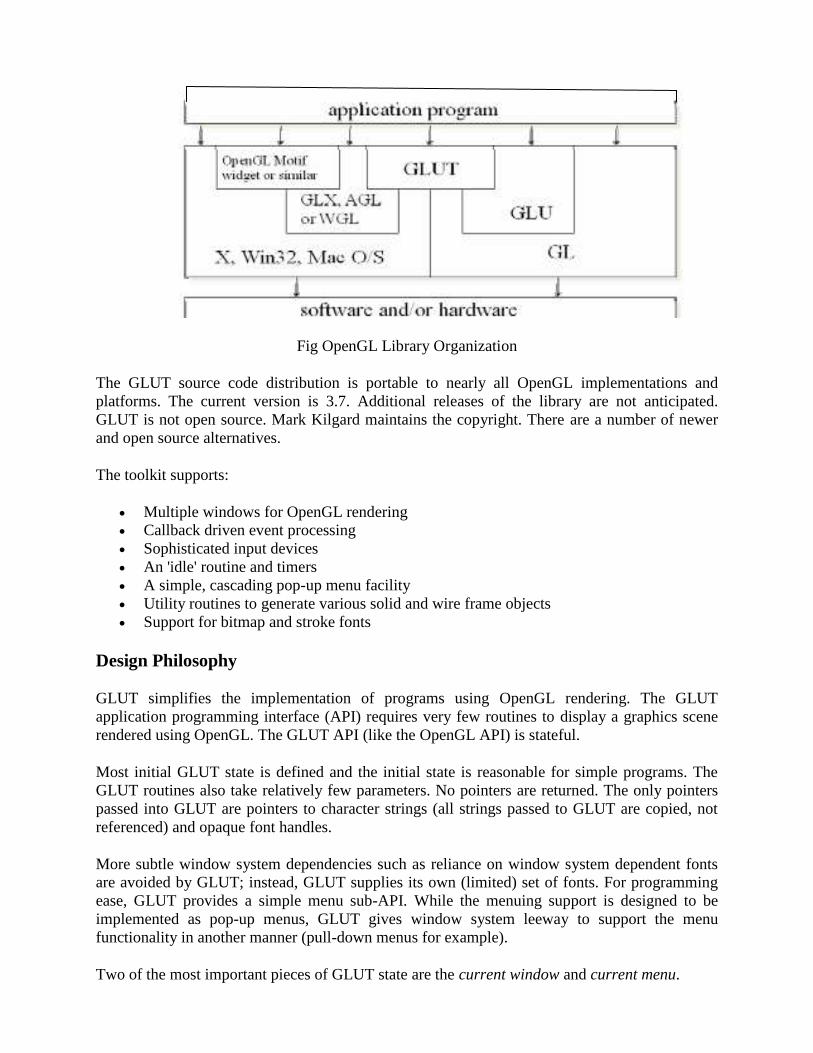
Fig OpenGL Library Organization
The GLUT source code distribution is portable to nearly all OpenGL implementations and
platforms. The current version is 3.7. Additional releases of the library are not anticipated.
GLUT is not open source. Mark Kilgard maintains the copyright. There are a number of newer
and open source alternatives.
The toolkit supports:
Multiple windows for OpenGL rendering
Callback driven event processing
Sophisticated input devices
An 'idle' routine and timers
A simple, cascading pop-up menu facility
Utility routines to generate various solid and wire frame objects
Support for bitmap and stroke fonts
Design Philosophy
GLUT simplifies the implementation of programs using OpenGL rendering. The GLUT
application programming interface (API) requires very few routines to display a graphics scene
rendered using OpenGL. The GLUT API (like the OpenGL API) is stateful.
Most initial GLUT state is defined and the initial state is reasonable for simple programs. The
GLUT routines also take relatively few parameters. No pointers are returned. The only pointers
passed into GLUT are pointers to character strings (all strings passed to GLUT are copied, not
referenced) and opaque font handles.
More subtle window system dependencies such as reliance on window system dependent fonts
are avoided by GLUT; instead, GLUT supplies its own (limited) set of fonts. For programming
ease, GLUT provides a simple menu sub-API. While the menuing support is designed to be
implemented as pop-up menus, GLUT gives window system leeway to support the menu
functionality in another manner (pull-down menus for example).
Two of the most important pieces of GLUT state are the current window and current menu.

Most window and menu routines affect the current window or menu respectively. Most callbacks
implicitly set the current window and menu to the appropriate window or menu responsible for
the callback.
GLUT contains routines for rendering fonts and geometric objects, however GLUT makes no
claims on the OpenGL display list name space. For this reason, none of the GLUT rendering
routines uses OpenGL display lists. It is up to the GLUT programmer to compile the output from
GLUT rendering routines into display lists if this is desired.
Installing OpenGL Libraries
Installation of OpenGL differs from operating system to another and from compiler to another,
because each system like Linux, Win, or Mac has different way of sorting system files, the same
issue with compilers, but since we are using Microsoft Visual Studio 2010 C++ then we are only
going to demonstrate how to install OpenGL on Windows system.
To install the OpenGL library all you have to do are the following steps:
Get the OpenGL library or the OpenGL Utility Toolkit Library files, and you can find GLUT on
the following links:
a. http://www.xmission/~nate/glut/glut-3.7.6-bin.zip
b. http://www.sultan-eid.com/files/glut-3.7.6-bin.rar
NOTE: Including the glut library will also provide the main GL functions which means you don't
have to include the both libraries, you can only include the GLUT and the program will
successfully works.
By extracting the compressed files you will find the following:
a. glut32.dll.
b. glut32.lib
c. glut.h
d. README-win32.
In order to write a Visual C++ application using GLUT you'll need three files:
· glut.h - This is the file you'll have to include in your source code. The common place to put this
file is in the gl folder which should be inside the include folder of your system.
· glut.lib (SGI version for Windows) and glut32.lib (Microsoft's version) - This file must be
linked to your application so make sure to put it your lib folder.

· glut32.dll (Windows) and glut.dll (SGI version for Windows) - choose one according to the
OpenGL you're using. If using Microsoft's version then you must choose glut32.dll. You should
place the dll file in your system folder.
To get the above mentioned files in the correct location, copy each file to the following indicated
folder:
· glut32.dll -> c: /windows/system32
· glut32.lib -> c:/program files/Microsoft visual 2010 /VC/Lib
· glut.h -> c:/program files/Microsoft visual 2010/VC/include/gl
It's important to consider that we are working on Microsoft Visual Studio 98 using C++, in case
you are using different compiler or different version of Microsoft Visual Studio, the installation
will take different paths.
Now you've completely installed OpenGL library into your machine and you are ready to go and
start programming using different graphical functions. In order to write applications with GLUT
you should have the latest version. The GLUT distribution comes with lots and lots of examples.
But let’s take a look at the syntax of OpenGL functions.
OpenGL: Conventions
Here’s the basic structure that we’ll be using in our applications. This is generally what you’d do
in your own OpenGL applications.
The steps are:
1) Choose the type of window that you need for your application and initialize it.
2) Initialize any OpenGL state that you don’t need to change every frame of your program. This
might include things like the background color, light positions and texture maps.
3) Register the callback functions that you’ll need. Callbacks are routines you write that GLUT
calls when a certain sequence of events occurs, like the window needing to be refreshed, or the
user moving the mouse. The most important callback function is the one to render your scene,
which we’ll discuss in a few slides.
4) Enter the main event processing loop. This is where your application receives events, and
schedules when callback functions are called.
GLUT window and screen coordinates are expressed in pixels. The upper left hand corner of the
screen or a window is (0, 0). X coordinates increase in a rightward direction; Y coordinates
increase in a downward direction.

Integer identifiers in GLUT begin with one, not zero. So window identifiers, menu identifiers,
and menu item indexes are based from one, not zero. The functions in OpenGL always start with
a specific prefix which is "gl" and a capitalized first character of each word in the name of
function syntax, which indicates that this function belongs to the OpenGL library.
In GLUT's ANSI C binding, for most routines, basic types ( int, char*) are used as parameters. In
routines where the parameters are directly passed to OpenGL routines, OpenGL types GLfloat
and GLint are used. The header files for GLUT should be included in GLUT programs with the
following include directive:
#include <GL/glut.h>
Because a very large window system software vendor (who will remain nameless) has an
apparent inability to appreciate that OpenGL's API is independent of their window system API,
portable ANSI C GLUT programs should not directly include <GL/gl.h> or <GL/glu.h>. Instead,
ANSI C GLUT programs should rely on <GL/glut.h> to include the necessary OpenGL and GLU
related header files.
GLUT programs need to link with the system's OpenGL and GLUT libraries (and any libraries
these libraries potentially depend on). A set of window system dependent libraries may also be
necessary for linking GLUT programs. For example, programs using the X11 GLUT
implementation typically need to link with Xlib, the X extension library, possibly the X Input
extension library, the X miscellaneous utilities library, and the math library.
Examples on OpenGL function formats:
Functions have prefix gl and initial capital letters for each word
glClearColor (), glEnable(), glPushMatrix () …
OpenGL data types
GLfloat, GLdouble, GLint, GLenum, …
glutInit
glutInit is used to initialize the GLUT library.
Usage
void glutInit(int *argc, char **argv);
argc
A pointer to the program's unmodified argc variable from main. Upon return, the value pointed
to by argc will be updated, because glutInit extracts any command line options intended for the
GLUT library.
argv

The program's unmodified argv variable from main. Like argc, the data for argv will be updated
because glutInit extracts any command line options understood by the GLUT library.
Description
glutInit will initialize the GLUT library and negotiate a session with the window system.
During this process, glutInit may cause the termination of the GLUT program with an error
message to the user if GLUT cannot be properly initialized. Examples of this situation include
the failure to connect to the window system, the lack of window system support for OpenGL,
and invalid command line options.
glutInit also processes command line options, but the specific options parse are window system
dependent.
glutInitWindowPosition, glutInitWindowSize
glutInitWindowPosition and glutInitWindowSize set the initial window position and size
respectively.
Usage
void glutInitWindowSize(int width, int height);
void glutInitWindowPosition(int x, int y);
width
Width in pixels.
height
Height in pixels.
x
Window X location in pixels.
y
Window Y location in pixels.
Description
Windows created by glutCreateWindow will be requested to be created with the current
initial window position and size.
GlutInitDisplayMode

glutInitDisplayMode sets the initial display mode.
Sample OpenGL Program:
/* This program draws a white rectangle on a black background.*/
#include <glut.h> /* glut.h includes gl.h and glu.h*/
void display()
{
glClear(GL_COLOR_BUFFER_BIT); /* clear window */
glBegin(GL_POLYGON); /* draw unit square polygon */
glVertex2f(-0.5, -0.5);
glVertex2f(-0.5, 0.5);
glVertex2f(0.5, 0.5);
glVertex2f(0.5, -0.5);
glEnd();
glFlush(); /* flush GL buffers */
}
void init() // initialize colors
{
glClearColor(0.0, 0.0, 0.0, 0.0); /* set clear color to black */
glColor3f(1.0, 1.0, 1.0); /* set fill color to white */
}
void main(int argc, char** argv)
{
/* Initialize mode */ /* Window title is name of program (arg[0]) */
glutInit(&argc,argv);

glutInitDisplayMode(GLUT_SINGLE | GLUT_RGB); //set color model
glutInitWindowSize(500, 500); // Set window Size
glutInitWindowPosition(0, 0); //Set Window Position upper left corner of screen
glutCreateWindow("simple"); //Create Window and Set title
glutDisplayFunc(display); //Call the Displaying function
init(); //Initialize Drawing Colors
glutMainLoop(); //Keep displaying until program is closed.
}
Output:
Conclusion: Thus we have studied about OpenGL and how it is used to draw graphics.
Lab Exercise 1: C
Tital: Study & implement of basic graphics function defined in graphics.h
Objective : Study of Graphics Functions.
Theory :
Arc function in c
Declaration: void arc(int x, int y, int stangle, int endangle, int radius);
arc function is used to draw an arc with center (x,y) and stangle specifies starting angle, endangle
specifies the end angle and last parameter specifies the radius of the arc. arc function can also be
used to draw a circle but for that starting angle and end angle should be 0 and 360 respectively.
C programming source code for arc
#include <graphics.h>
#include <conio.h>
main()
{
int gd = DETECT, gm;
initgraph(&gd, &gm, "C:\\TC\\BGI");
arc(100, 100, 0, 135, 50);
getch();
closegraph();
return 0;
}
Bar function in c
1. In the above program (100,100) are coordinates of center of arc, 0 is the starting angle, 135
is the end angle and 50 specifies the radius of the arc.
Declaration: void bar(int left, int top, int right, int bottom);
Bar function is used to draw a 2-dimensional, rectangular filled in bar . Coordinates of
left top and right bottom corner are required to draw the bar. Left specifies the X-
coordinate of top left corner, top specifies the Y-coordinate of top left corner, right
specifies the X-coordinate of right bottom corner, bottom specifies the Y-coordinate of
right bottom corner. Current fill pattern and fill color is used to fill the bar. To change fill
pattern and fill color use setfillstyle.
2. C programming code
3. #include <graphics.h>
4. #include <conio.h>
5.
6. main()
7. {
8. int gd = DETECT, gm;
9.
10. initgraph(&gd, &gm, "C:\\TC\\BGI");
11. 12. bar(100, 100, 200, 200);
13. 14. getch();
15. closegraph();
16. return 0;
17. }
18.
C program for cleardevice
Declaration: void cleardevice();
cleardevice function clears the screen in graphics mode and sets the current position to (0,0).
Clearing the screen consists of filling the screen with current background color.
C program for cleardevice
#include <graphics.h>
#include <conio.h>
main()
{
int gd = DETECT, gm;
initgraph(&gd, &gm, "C:\\TC\\BGI");
outtext("Press any key to clear the screen.");
getch();
cleardevice();
outtext("Press any key to exit...");
getch();
closegraph();
return 0;
}
Note : Don't use clrscr in graphics mode
C code of closegraph
closegraph function closes the graphics mode, deallocates all memory allocated by graphics
system and restores the screen to the mode it was in before you called initgraph.
Declaration: void closegraph();
C code of closegraph
#include<graphics.h>
#include<conio.h>
main()
{
int gd = DETECT, gm;
initgraph(&gd, &gm, "C:\\TC\\BGI");
outtext("Press any key to close the graphics mode...");
getch();
closegraph();
return 0;
}
C program for drawpoly
Drawpoly function is used to draw polygons i.e. triangle, rectangle, pentagon, hexagon etc.
Declaration: void drawpoly( int num, int *polypoints );
num indicates (n+1) number of points where n is the number of vertices in a polygon, polypoints
points to a sequence of (n*2) integers . Each pair of integers gives x and y coordinates of a point
on the polygon. We specify (n+1) points as first point coordinates should be equal to (n+1)th
to
draw a complete figure.
To understand more clearly we will draw a triangle using drawpoly, consider for example,the
array :-
int points[] = { 320, 150, 420, 300, 250, 300, 320, 150};
points array contains coordinates of triangle which are (320, 150), (420, 300) and (250, 300).
Note that last point(320, 150) in array is same as first. See the program below and then its output,
it will further clear your understanding.
C program for drawpoly
#include <graphics.h>
#include <conio.h>
main()
{
int gd=DETECT,gm,points[]={320,150,420,300,250,300,320,150};
initgraph(&gd, &gm, "C:\\TC\\BGI");
drawpoly(4, points);

getch();
closegraph();
return 0;
}
Declarations of ellipse function :-
void ellipse(int x, int y, int stangle, int endangle, int xradius, int yradius);
Ellipse is used to draw an ellipse (x,y) are coordinates of center of the ellipse, stangle is the
starting angle, end angle is the ending angle, and fifth and sixth parameters specifies the X and Y
radius of the ellipse. To draw a complete ellipse strangles and end angle should be 0 and 360
respectively.
C programming code for ellipse
#include<graphics.h>
#include<conio.h>
main()
{
int gd = DETECT, gm;
initgraph(&gd, &gm, "C:\\TC\\BGI");
ellipse(100, 100, 0, 360, 50, 25);
getch();
closegraph();
return 0;
}
Declaration of fillellipse function :-
void fillellipse(int x, int y, int xradius, int yradius);
x and y are coordinates of center of the ellipse, xradius and yradius are x and y radius of ellipse
respectively.
C program for fillellipse
#include <graphics.h>
#include <conio.h>
int main()
{
int gd = DETECT, gm;
initgraph(&gd, &gm, "C:\\TC\\BGI");
fillellipse(100, 100, 50, 25);
getch();
closegraph();
return 0;
}
Fillpoly function draws and fills a polygon. It require same arguments as drawpoly.
Declaration: void drawpoly( int num, int *polypoints );
For details of arguments see drawpoly.
fillpoly fills using current fill pattern and color which can be changed using setfillstyle.
C programming code
#include <graphics.h>
#include <conio.h>
main()
{
int gd=DETECT,gm,points[]={320,150,440,340,230,340,320,150};
initgraph(&gd, &gm, "C:\\TC\\BGI");
fillpoly(4, points);
getch();
closegraph();
return 0;
}
Declaration: void floodfill(int x, int y, int border);
floodfill function is used to fill an enclosed area. Current fill pattern and fill color is used to fill
the area.(x, y) is any point on the screen if (x,y) lies inside the area then inside will be filled
otherwise outside will be filled,border specifies the color of boundary of area. To change fill
pattern and fill color use setfillstyle. Code given below draws a circle and then fills it.
C programming code
#include <graphics.h>
#include <conio.h>
main()
{
int gd = DETECT, gm;
initgraph(&gd, &gm, "C:\\TC\\BGI");
setcolor(RED);
circle(100,100,50);
floodfill(100,100,RED);
getch();
closegraph();
return 0;
}

In the above program a circle is drawn in RED color. Point (100,100) lies inside the circle as it is
the center of circle, third argument to floodfill is RED which is color of boundary of circle. So
the output of above program will be a circle filled with WHITE color as it is the default fill color.
Declaration: void getarccoords(struct arccoordstype *var);
getarccoords function is used to get coordinates of arc which is drawn most recently.
arccoordstype is a predefined structure which is defined as follows:
struct arccoordstype
{
int x, y; /* center point of arc */
int xstart, ystart; /* start position */
int xend, yend; /* end position */
};
address of a structure variable of type arccoordstype is passed to function getarccoords.
C program of getarccoords
#include<graphics.h>
#include<conio.h>
#include<stdio.h>
main()
{
int gd = DETECT, gm;
struct arccoordstype a;
char arr[100];
initgraph(&gd, &gm,"C:\\TC\\BGI");
arc(250,200,0,90,100);
getarccoords(&a);
sprintf(arr,"(%d, %d)",a.xstart,a.ystart);
outtextxy(360,195,arr);
sprintf(arr,"(%d, %d)",a.xend,a.yend);
outtextxy(245,85,arr);
getch();
closegraph();
return 0;
}
In the above program we have drawn an arc and then we get the coordinates of end points of arc
using getarccoords.Coordinates so obtained are displayed using outtextxy.
getbkcolor function returns the current background color

Declaration : int getbkcolor();
e.g. color = getbkcolor(); // color is an int variable
if current background color is GREEN then color will be 2.
C program for getbkcolor
#include<graphics.h>
#include<conio.h>
main()
{
int gd = DETECT, gm, bkcolor;
char a[100];
initgraph(&gd,&gm,"C:\\TC\\BGI");
bkcolor = getbkcolor();
sprintf(a,"Current background color = %d", bkcolor);
outtextxy( 10, 10, a);
getch();
closegraph();
return 0;
}
getdrivername function returns a pointer to the current graphics driver.
C program for getdrivername
#include<graphics.h>
#include<conio.h>
main()
{
int gd = DETECT, gm;
char *drivername;
initgraph(&gd, &gm, "C:\\TC\\BGI");
drivername = getdrivername();
outtextxy(200, 200, drivername);
getch();
closegraph();
return 0;
}
getimage function saves a bit image of specified region into memory, region can be any
rectangle.

Declaration:- void getimage(int left, int top, int right, int bottom, void *bitmap);
getimage copies an image from screen to memory. Left, top, right, and bottom define the area of
the screen from which the rectangle is to be copied, bitmap points to the area in memory where
the bit image is stored.
Smiling face animation program using getimage.
getmaxcolor function returns maximum color value for current graphics mode and driver. Total
number of colors available for current graphics mode and driver are ( getmaxcolor() + 1 ) as
color numbering starts from zero.
Declaration: int getmaxcolor();
C program of getmaxcolor
#include<graphics.h>
#include<conio.h>
main()
{
int gd = DETECT, gm, max_colors;
char a[100];
initgraph(&gd,&gm,"C:\\TC\\BGI");
max_colors = getmaxcolor();
sprintf(a,"Maximum number of colors for current graphics mode and driver =
%d",max_colors+1);
outtextxy(0, 40, a);
getch();
closegraph();
return 0;
}
getmaxy function returns the maximum Y coordinate for current graphics mode and driver.
Declaration: int getmaxy();
C program for getmaxy
#include<graphics.h>
#include<conio.h>
main()
{
int gd = DETECT, gm, max_y;
char array[100];
initgraph(&gd,&gm,"C:\\TC\\BGI");
max_y = getmaxy();
sprintf(array, "Maximum Y coordinate for current graphics mode and driver is = %d.",max_y);
outtext(array);
getch();
closegraph();
return 0;
}
getmaxcolor function returns maximum color value for current graphics mode and driver. Total
number of colors available for current graphics mode and driver are ( getmaxcolor() + 1 ) as
color numbering starts from zero.
Declaration: int getmaxcolor();
C program of getmaxcolor
#include<graphics.h>
#include<conio.h>
main()
{
int gd = DETECT, gm, max_colors;
char a[100];
initgraph(&gd,&gm,"C:\\TC\\BGI");
max_colors = getmaxcolor();
sprintf(a,"Maximum number of colors for current graphics mode and driver =
%d",max_colors+1);
outtextxy(0, 40, a);
getch();
closegraph();
return 0;
}

Lab Exercise 2:A
Title- Study of graphics standards
Objective: To gain knowledge of different graphics standards.
Theory:
3D Core Graphics System
The 3D Core Graphics System was the very first graphical standard ever developed. A group of
25 experts of the ACM Special Interest Group SIGGRAPH developed this "conceptual
framework". The specifications were published in 1977 and it became a foundation for many
future developments in the field of computer graphics.
GKS ( Graphical Kernel System)
The Graphical Kernel System (GKS) is a document produced by the International Standards
Organization (ISO) which defines a common interface to interactive computer graphics for
application programs. GKS has been designed by a group of experts representing the national
standards institutions of most major industrialized countries. The full standard provides
functional specifications for some 200 subroutines which perform graphics input and output in a
device independent way. Application programs can thus move freely between different graphics
devices and different host computers. For the first time graphics programs have become
genuinely portable.
However, one should point out that GKS itself is not portable. Individual GKS implementations
will vary substantially as they have to support different graphics devices on different computers.
Moreover, GKS is a kernel system, and thus does not include an arbitrary collection of functions
to produce histograms or contour plots, etc. Such facilities are regarded as applications which sit
on top of the basic graphics package and, at CERN, they are provided by the Graphical
Extensions to the NAG Library , or the HPLOT package .
In order to allow particular applications to choose a graphics package with the appropriate
capability, GKS has been defined to have different levels. The level structure has two
dimensions, one for output (0, 1, or 2) and one for input (a, b, or c). Higher levels include the
capabilities of lower levels. In the United States, ANSI has defined also a level 'm', for very
simple applications, which sits below output level '0'. Most implementations provide all output
(level '2') and intermediate input (level 'b'). The reason input level 'c' is not usually supported is
that it requires asynchronous input facilities not found in all operating systems.
The GKS functions have been defined independently from a specific programming language, and
bindings to individual languages are subject to separate standards efforts which have been
undertaken for all the major languages.

The Graphical Kernel System for two dimensional graphics was adopted as an ISO standard in
1985, and since that date work has been in progress to define a three dimensional super-set
which was accepted as an International Standard during 1988. The FORTRAN binding to GKS-
3D has also been published as a Draft International Standard.
The GKS functions are separated into those which pass values to GKS for control, setting or
output, and those which inquire about status information. There are 8 distinct classes:
1. Control functions
2. Output Attributes
3. Output Primitives
4. Segment functions
5. Transformations functions
6. Input functions
7. Metafile functions
8. Inquiry functions
PHIGS
PHIGS (Programmer's Hierarchical Interactive Graphics System) is an API standard for
rendering 3D computer graphics, considered to be the 3D graphics standard for the 1980s
through the early 1990s. Subsequently, a combination of features and power led to the rise of
OpenGL, which became the most popular professional 3D API of the mid to late 1990s.
PHIGS was available as a standalone implementation (examples: Digital Equipment
Corporation's DEC PHIGS, IBM's graPHIGS, Sun's SunPHIGS) and also used with the X
Window system, supported via PEX (originally known as the "PHIGS Extension to X";
subsequently referred to as "X3d", whose letters form a rotational variant on the letters "P-E-X").
PEX consisted of an extension to X, adding commands that would be forwarded from the X
server to the PEX system for rendering. Workstations were placed in windows typically, but
could also be forwarded to take over the whole screen, or to various printer-output devices.
PHIGS was designed in the 1980s, inheriting many of its ideas from the Graphical Kernel
System of the late 1970s, and became a standard by 1989: ANSI (ANSI X3.144-1988), FIPS
(FIPS 153) and then ISO (ISO/IEC 9592 and ISO/IEC 9593). Due to its early gestation, the
standard supports only the most basic 3D graphics, including basic geometry and meshes, and
only the basic Gouraud, "Dot", and Phong shading for rendering scenes. Although PHIGS
ultimately expanded to contain advanced functions (including the more accurate Phong lighting
model and Data Mapping), other features considered standard by the mid-1990s were not
supported (notably texture mapping), nor were many machines of the era physically capable of
optimizing it to perform in real time.

The word "hierarchical" in the name refers to a notable feature of PHIGS: unlike most graphics
systems, PHIGS included a scene graph system as a part of the basic standard. Models were built
up in a Centralized Structure Store (CSS), a database containing a "world" including both the
drawing primitives and their attributes (color, line style, etc.). CSSes could be shared among a
number of virtual devices, known under PHIGS as workstations, each of which could contain
any number of "views".
Displaying graphics on the screen in PHIGS was a three-step process; first the model would be
built into a CSS, then a workstation would be created and opened, and finally the model would
be connected to the workstation. At that point the workstation would immediately render the
model, and any future changes made to the model would instantly be reflected in all applicable
workstation views.
PHIGS originally lacked the capability to render illuminated scenes, and was superseded by
PHIGS+. PHIGS+ works in essentially the same manner, but added methods for lighting and
filling surfaces within a 3D scene. PHIGS+ also introduced more advanced graphics primitives,
such as Nonuniform Rational B-spline (NURBS) surfaces. An ad hoc ANSI committee was
formed around these proposed extensions to PHIGS, changing its name to the more descriptive
and (optimistically) extensible name "PHIGS PLUS" -- "PLUS" being a slightly tongue-in-cheek
acronym for "Plus Lumière Und Surfaces" (the two major areas of advancement over the base
PHIGS standard).
The rise of OpenGL and the decline of PHIGS
OpenGL, unlike PHIGS, was an immediate-mode rendering system with no "state"; once an
object is sent to a view to be rendered it essentially disappears. Changes to the model had to be
re-sent into the system and re-rendered, a dramatically different programming mindset. For
simple projects, PHIGS was considerably easier to use and work with.
However, OpenGL's "low-level" API allowed the programmer to make dramatic improvements
in rendering performance by first examining the data on the CPU-side before trying to send it
over the bus to the graphics engine. For instance, the programmer could "cull" the objects by
examining which objects were actually visible in the scene, and sending only those objects that
would actually end up on the screen. This was kept private in PHIGS, making it much more
difficult to tune performance, but enabling tuning to happen "for free" within the PHIGS
implementation.
Given the low performance systems of the era and the need for high-performance rendering,
OpenGL was generally considered to be much more "powerful" for 3D programming. PHIGS
fell into disuse. Version 6.0 of the PEX protocol was designed to support other 3D programming
models as well, but did not regain popularity. PEX was mostly removed from XFree86 4.2.x
(2002) and finally removed from the X Window System altogether in X11R6.7.0
CGM (Computer Graphics Metafile)
All graphical elements can be specified in a textual source file that can be compiled into a binary
file or one of two text representations. CGM provides a means of graphics data interchange for
computer representation of 2D graphical information independent from any particular
application, system, platform, or device. As a metafile, i.e., a file containing information that
describes or specifies another file, the CGM format has numerous elements to provide functions
and to represent entities, so that a wide range of graphical information and geometric primitives
can be accommodated. Rather than establish an explicit graphics file format, CGM contains the
instructions and data for reconstructing graphical components to render an image using an
object-oriented approach.
Although CGM is not widely supported for web pages and has been supplanted by other formats
in the graphic arts, it is still prevalent in engineering, aviation, and other technical applications.
The initial CGM implementation was effectively a streamed representation of a sequence of
Graphical Kernel System primitive operations. It has been adopted to some extent in the areas of
technical illustration and professional design, but has largely been superseded by formats such as
SVG and DXF.
The World Wide Web Consortium has developed WebCGM, a profile of CGM intended for the
use of CGM on the Web.
Conclusion: Thus we studied the different graphics standard and how they are evolved and
contributed to graphics systems.

Lab Exercise 2: B
Title- Program for DDA Line Drawing Algorithm
Objective : To study DDA line drawing algorithms.
Theory:
Line Drawing Algorithm:
Digital Differential Analyzer (DDA) Line Algorithm
1. Start
2. Declare variables required for drawing two co-ordinates and the difference between them.
3. Input the two line end-points.
4. Calculate the difference between x co-ordinates and y co-ordinates of two points say dx
and dy.
5. Then if dx>dy then length=dx.
6. Otherwise lentgth=dy.
7. Calculate increment value for next point xincrement=dx/length and
yincrement=dy/length.
8. Start a loop k=0 and continuing till k<length ,the points will be
i. x=x+xincrement
ii.y=y+yincrement
9. Draw the new co-rdinates till we rich the length of the line.
10. Stop.
// Program to draw a line using DDA Algorithm
#include <stdio.h>
#include <math.h>
#include <glut.h>
GLdouble X1=100, Y1=100, X2=450, Y2=350; // define line end points
void LineDDA(void)
{
GLdouble dx=X2-X1 , dy=Y2-Y1,steps; // calculate diff betn line end points
float xInc,yInc,x=X1,y=Y1;

steps=(abs(dx)>abs(dy))?abs(dx):abs(dy); //max diff is length
xInc=dx/(float)steps;
yInc=dy/(float)steps;
glClear(GL_COLOR_BUFFER_BIT);
glBegin(GL_POINTS);
glVertex2d(x,y); //plot initial point
for(int k=0;k<steps;k++)
{
x+=xInc; //decide next incremented x co-ord
y+=yInc; //decide next incremented y co-ord
glVertex2d(x,y); //plot each incremented point till length
}
glEnd();
glFlush();
}
void Init()
{
glClearColor(1.0,1.0,0.0,0.0); //set window color and alpha value
glColor3f(0.0,0.0,0.0); //set line color
glViewport(0 , 0 , 640 , 480); //set viewport
glMatrixMode(GL_PROJECTION);
glLoadIdentity();
gluOrtho2D(0 , 640 , 0 , 480); //set viewing rectangle
}
void main(int argc, char **argv)
{
glutInit(&argc,argv);
glutInitDisplayMode(GLUT_SINGLE | GLUT_RGB); //set color model
glutInitWindowSize(640,480); //set window size
glutInitWindowPosition(0,0); //set initial window position
glutCreateWindow("LineDDA"); //set window title
Init();
glutDisplayFunc(LineDDA);
glutMainLoop();
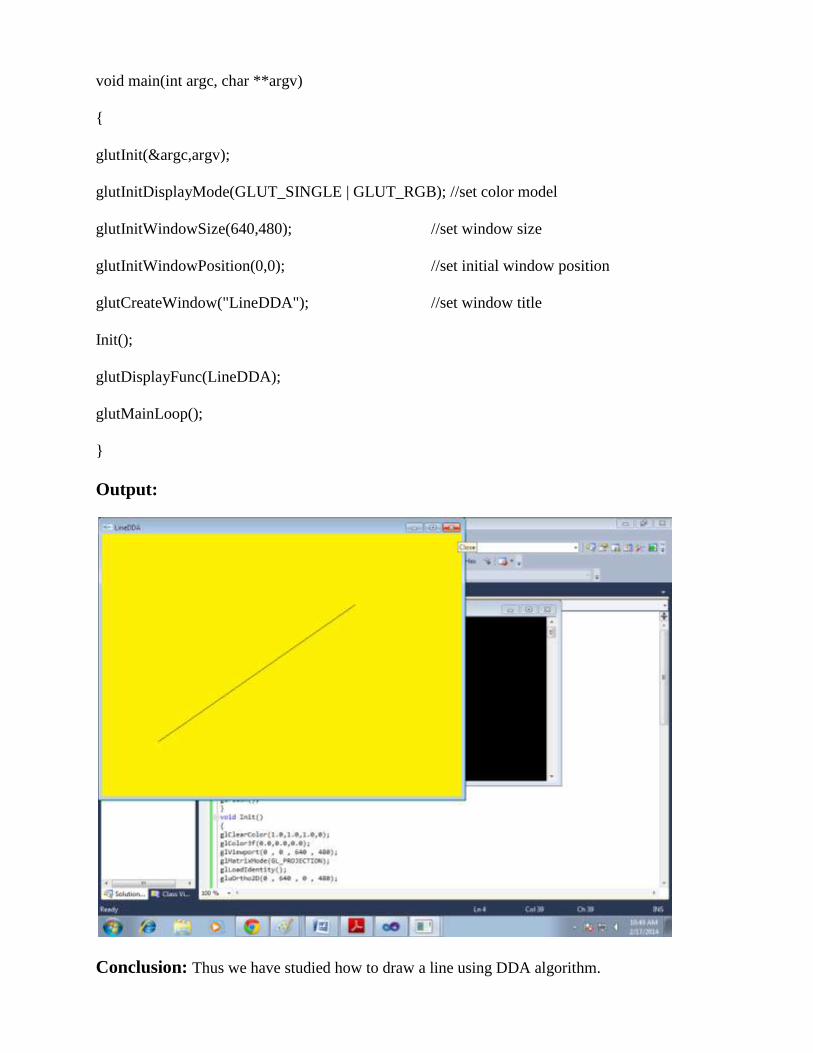
}
Output:
Conclusion: Thus we have studied how to draw a line using DDA algorithm.

Lab Exercise 3
Title - Program for Bresenham Line Drawing
Algorithm
Objective:To study Bresenham line drawing algorithm.
Theory:
Bresenham’s Line Algorithm
Bresenham’s line algorithm properties:
· Only uses incremental integer calculations.
· Can be adapted to display circles and other curves.
· Basic idea find next pixel from current one
1. Start
2. Declare variables required for drawing two co-ordinates and the difference between them.
3. Input the two line end-points and store left end-points in (x1,y1).
4. Plot first point (x1,y1) and calculate the difference between x co-ordinates and y co-
ordinates of two points say dx and dy and obtain the initial value of decision parameter p
as p=(2dy-dx).
5. Starting from first point (x,y) perform the following test.
6. Repeat step 7 while (x<=x2).
7. If p<0 next point is (x+1,y) and p=(p+2dy).
8. Otherwise ,the next point to plot is (x+1,y+1) and p=(p+2dy-2dx).
9. Plot the pixels at points (x,y) in specified color.
10. Stop.
// Program to draw a line using Bresenham’s Algorithm (works only for |m| < 1)
#include <GL/glut.h>
#include <stdio.h>
#include <math.h>
void init(void)
{
glClearColor(1.0,1.0,1.0,0.0);
glMatrixMode(GL_PROJECTION);
gluOrtho2D(0.0,400.0,0.0,400.0);
}

void setPixel(GLint x,GLint y)
{
glBegin(GL_POINTS);
glVertex2i(x,y);
glEnd();
}
void line()
{
int x0 = 50, y0=50, xn = 300, yn = 150, x, y;
int dx, dy, //deltas
pk, //decision parameter
k; //looping variable
glClear(GL_COLOR_BUFFER_BIT);
glColor3f( 1 ,0, 0);
setPixel(x0, y0); //plot first point
// difference between starting and ending points
dx = xn - x0;
dy = yn - y0;
pk = 2 * dy - dx;
x = x0; y = y0;
for ( k = 0; k < dx-1; ++k )
{
if ( pk < 0 )
{
pk = pk + 2 * dy; //calculate next pk
//next pixel: (x+1, y )
}
else
{
pk = pk + 2*dy - 2*dx; //next pixel: (x+1, y+1
++y; //calculate next pk
}
++x;
setPixel( x, y );
}
glFlush();
}
int main(int argc,char **argv)
{
glutInit(&argc,argv);
glutInitDisplayMode(GLUT_SINGLE|GLUT_RGB); //set color model
glutInitWindowPosition(0,0); //set initial window position
glutInitWindowSize(500,500); //set window size
glutCreateWindow("Bresenham Line"); //set window title
init();
glutDisplayFunc( line ); //call line function
glutMainLoop();
return 0;
}
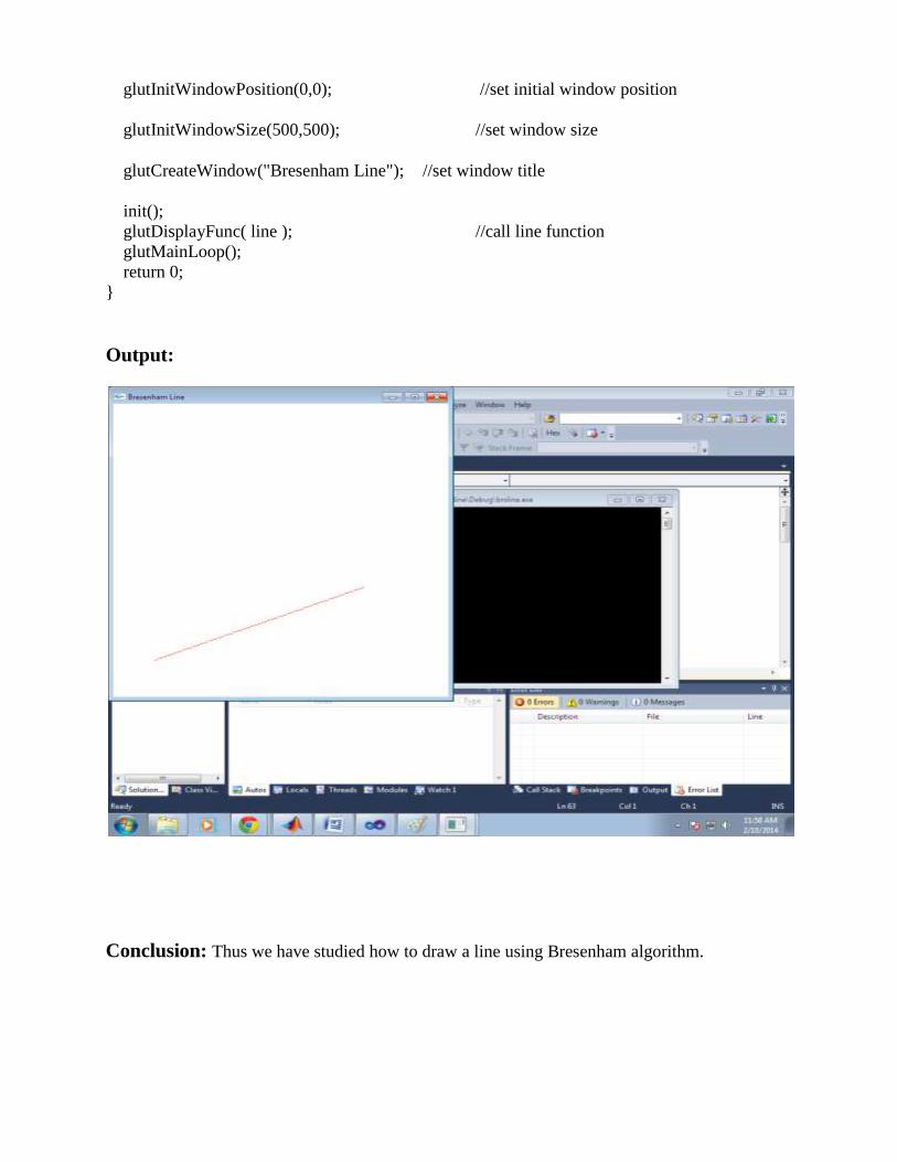
Output:
Conclusion: Thus we have studied how to draw a line using Bresenham algorithm.

Lab Exercise 4
Title - Program for Mid-Point Circle Generation
Algorithm
Objective: To study mid-point circle generation algorithm.
Theory: Circles have the property of being highly symmetrical, which is handy when it comes to
drawing them on a display screen.
We know that there are 360 degrees in a circle. First we see that a circle is symmetrical about the x axis,
so only the first 180 degrees need to be calculated.
Next we see that it's also symmetrical about the y axis, so now we only need to calculate the first 90
degrees.
Finally we see that the circle is also symmetrical about the 45 degree diagonal axis, so we only needto
calculate the first 45 degrees.We only need to calculate the values on the border of the circle in the first
octant. The other valuesmay be determined by symmetry.
// Program:
#include<dos.h>
#include<stdio.h>
#include<conio.h>
#include<graphics.h>
void draw_circle(int,int,int);
void symmetry(int,int,int,int);
void main()
{
int xc,yc,R;
int gd=DETECT,gm;
initgraph(&gd,&gm,"C:\\TurboC3\\BGI");
printf("Enter the center of the circle:\n");
printf("Xc =");
scanf("%d",&xc);
printf("Yc =");
scanf("%d",&yc);
printf("Enter the radius of the circle :");
scanf("%d",&R);
draw_circle(xc,yc,R);
getch();
closegraph();
}
void draw_circle(int xc,int yc,int rad)
{
int x = 0;
int y = rad;
int p = 1-rad;
symmetry(x,y,xc,yc);
for(x=0;y>x;x++)
{
if(p<0)
p += 2*x + 3;
else
{
p += 2*(x-y) + 5;
y--;
}
symmetry(x,y,xc,yc);
delay(50);
}
}
void symmetry(int x,int y,int xc,int yc)
{
putpixel(xc+x,yc-y,GREEN); //For pixel (x,y)
delay(50);
putpixel(xc+y,yc-x, GREEN); //For pixel (y,x)
delay(50);

putpixel(xc+y,yc+x, GREEN); //For pixel (y,-x) delay(50); putpixel(xc+x,yc+y, GREEN); //For pixel (x,-y) delay(50); putpixel(xc-x,yc+y, GREEN); //For pixel (-x,-y) delay(50); putpixel(xc-y,yc+x, GREEN); //For pixel (-y,-x) delay(50); putpixel(xc-y,yc-x, GREEN); //For pixel (-y,x) delay(50); putpixel(xc-x,yc-y, GREEN); //For pixel (-x,y) delay(50); }
Output:
Conclusion: Thus we have studied Mid-point circle generation algorithm.

Lab Exercise 5
Title- Drawing Basic Graphics Primitives
Objective: To study basic graphics primitives/entities and respective OpenGL functions to
implement them.
Theory:


/* hello.c This is a simple, introductory OpenGL program */
#include <GL/glut.h>
void display(void)
{
glClear (GL_COLOR_BUFFER_BIT); /* clear all pixels */
glColor3f (1.0, 0.0, 1.0);
glBegin(GL_POLYGON); /* draw magenta polygon (rectangle)*/
glVertex3f (-0.15, -0.15, 0.0); /*with corners at (0.25,0.25,0.0) */
glVertex3f (0.65, -0.15, 0.0); /*(0.75, 0.75, 0.0) */
glVertex3f (0.65, 0.65, 0.0);
glVertex3f (-0.15, 0.65, 0.0);
glEnd();
glColor3f (1.0, 1.0, 0.0);
glBegin(GL_POINTS);
glVertex3f(0.70f, 0.50f, -0.60f);
glEnd( );
glColor3f (0.0, 1.0, 1.0);
glBegin(GL_LINES);
glVertex3f(-0.10f, -0.50f, 0.90f); // origin of the line
glVertex3f(0.90f, -0.80f, -0.80f); // ending point of the line
glEnd( );
glColor3f (1.0, 1.0, 1.0);
glBegin(GL_TRIANGLES);
glVertex3f(-0.50f, -0.25f, 0.0f);
glVertex3f(-0.55f, 0.30f, 0.0f);
glVertex3f(0.15f,- 0.50f, 0.0f);
glEnd( );
glFlush ();
glutMainLoop();
}
int main(int argc, char** argv)
{
glutInit(&argc, argv);
glutInitDisplayMode (GLUT_SINGLE | GLUT_RGB); /*Declare initial
window display mode (single buffer and RGBA*/
glutInitWindowSize (650, 550); // Declare initial window size
glutInitWindowPosition (200, 200); // Declare initial window position
glutCreateWindow ("Simple Demo"); //set window title
glutDisplayFunc(display); //Register callback function to display graphics
glutMainLoop(); // Enter main loop and process events.
return 0;
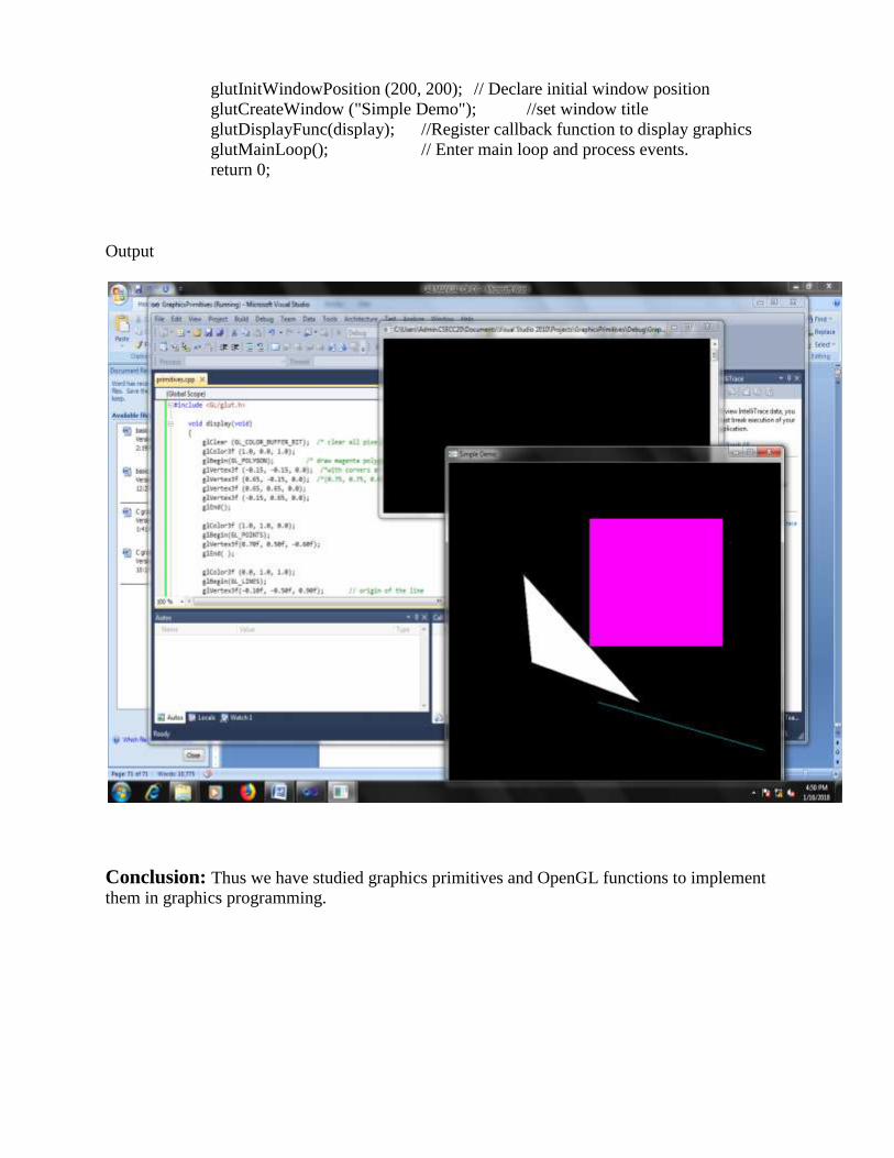
Output
Conclusion: Thus we have studied graphics primitives and OpenGL functions to implement
them in graphics programming.
Lab Exercise 6
Title – Program using Keyboard/Mouse in OpenGL.
Objective: To study keyboard function & Mouse function.
Theory:
//Program
int main(int argc, char **argv)
{
initGLUT(argc, argv); initGL(); //Set the display callback
glutDisplayFunc(draw); //Set the keyboard callback
glutKeyboardFunc(keyboard); //Start the GLUT main event loop.
glutMainLoop(); return 0;
}//keyboard callback
void keyboard(unsigned char key, int x, int y)
{ switch(key)
{
case 'r': r=1.0; g=0.0; b=0.0; break; case 'g': r=0.0; g=1.0; b=0.0;
break;
}
glutPostRedisplay();
}
void draw()
{
... //draw a polygon

glColor3f( r, g, b );
glBegin( GL_POLYGON );
glVertex2f( 0.25, 0.25 );
glVertex2f( 0.75, 0.5 );
glVertex2fv( point2 );
glEnd(); ... }
Output

Conclusion: Thus we have studied the keyboard Interaction.
Mouse Interaction
int main(int argc, char **argv)
{ ...
//Set the keyboard callback
glutKeyboardFunc(keyboard);
glutMouseFunc(mouse);
glutPassiveMotionFunc(passiveMotion);
glutMotionFunc(motion);
... }
void draw()
{ ... //draw a point
glColor3f( 0.8, 0.8, 0.2 );
glPointSize(10.0);
glBegin( GL_POINTS );
glVertex2f( pos_x, pos_y );
glEnd();
... }

Conclusion: Thus we have studied the mouse Interaction.

Lab Exercise 7
Title - Program using Menu / Submenu in OpenGL
Objective: To study Menu & Submenu in opengl.
Theory :
GLUT supports simple cascading pop-up menus. They are designed to let a user select various
modes within a program. The functionality is simple and minimalistic and is meant to be that
way. Do not mistake GLUT’s pop-up menu facility with an attempt to create a full-featured user
interface. glutCreateMenu creates a Menu in GLUT. The syntax of glutCreateMenu is
int glutCreateMenu(void (*func)(int value));
This function defines the callback that has to be called when a menu item was selected. This
callback function has one parameter, the value. This function returns an int, this is the menu
identifier. This identifier is needed when you would want to attach this menu as a submenu. This
is illustrated in sample example later.
void glutAddMenuEntry(char *name, int value);
This adds an entry to the menu with the label defined by name and the second parameter is the
value that will be passed to the callback function. The menu is being added to the current menu.
Each menu entry that is being added is added at the bottom of the current menu.
void glutAddSubMenu(char *name, int menu);
This adds the menu identified by the menu identifier as submenu with a given name to the
current menu. The program won’t work if it contains an infinite loop of menus.
void glutAttachMenu(int button);
This attaches the current menu to a certain (mouse) event, you can let a menu listen to a specified
mouse button, button can be one of the following:GLUT_LEFT_BUTTON, GLUT_MIDDLE_BUTTON,
and GLUT_RIGHT_BUTTON. You can also detach the menu using void glutDetachMenu(int
button);.
// Program #include <windows.h> #include <GL/glut.h> static int window; static int menu_id; static int submenu_id; static int value = 0; void menu(int num){ if(num == 0){

glutDestroyWindow(window); exit(0); }else{ value = num; } glutPostRedisplay(); } void createMenu(void){ submenu_id = glutCreateMenu(menu); glutAddMenuEntry("Sphere", 2); glutAddMenuEntry("Cone", 3); glutAddMenuEntry("Torus", 4); glutAddMenuEntry("Teapot", 5); menu_id = glutCreateMenu(menu); glutAddMenuEntry("Clear", 1); glutAddSubMenu("Draw", submenu_id); glutAddMenuEntry("Quit", 0); glutAttachMenu(GLUT_RIGHT_BUTTON); } void display(void){ glClear(GL_COLOR_BUFFER_BIT); if(value == 1){ return; //glutPostRedisplay(); }else if(value == 2){ glPushMatrix(); glColor3d(1.0, 0.0, 0.0); glutWireSphere(0.5, 50, 50); glPopMatrix(); }else if(value == 3){ glPushMatrix(); glColor3d(0.0, 1.0, 0.0); glRotated(65, -1.0, 0.0, 0.0); glutWireCone(0.5, 1.0, 50, 50); glPopMatrix(); }else if(value == 4){ glPushMatrix(); glColor3d(0.0, 0.0, 1.0); glutWireTorus(0.3,0.6,100,100); glPopMatrix(); }else if(value == 5){ glPushMatrix(); glColor3d(1.0, 0.0, 1.0); glutSolidTeapot(0.5); glPopMatrix(); } glFlush(); } int main(int argc, char **argv){ glutInit(&argc, argv); glutInitDisplayMode(GLUT_RGBA | GLUT_SINGLE); glutInitWindowSize(500,500); glutInitWindowPosition(100,100); window = glutCreateWindow("Menus and Submenus - Programming Techniques"); createMenu(); glClearColor(0.0,0.0,0.0,0.0); glutDisplayFunc(display); glutMainLoop(); return EXIT_SUCCESS; }
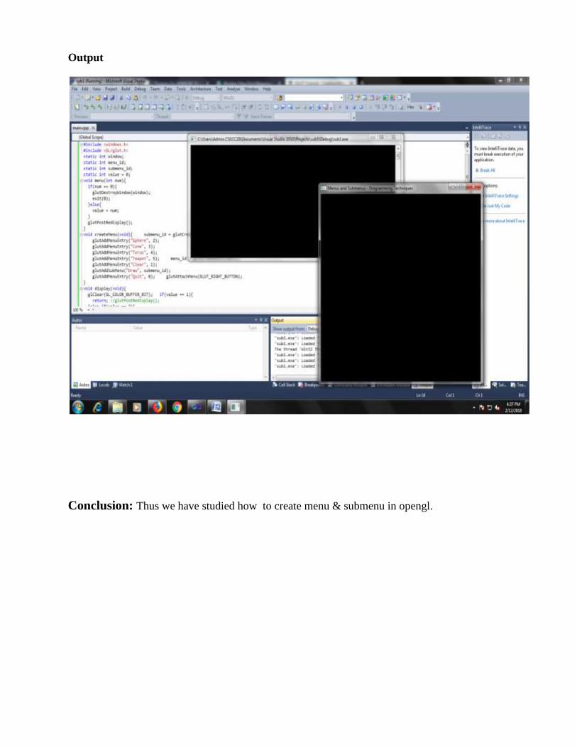
Output
Conclusion: Thus we have studied how to create menu & submenu in opengl.

Lab Exercise 8
Title - Program using 2-D Transformation
Objective: To study basic transformation and how to apply them on graphics objects.
Theory:
Geometric image transformation functions use mathematical transformations to crop,
pad, scale, rotate, transpose or otherwise alter an image array to produce a modified view of
an image. A transformation thus is the process of mapping points to other locations. Common
transformations are Translation, Scaling and Rotation.
When an image undergoes a geometric transformation, some or all of the pixels within the source
image are relocated from their original spatial coordinates to a new position in the output image.
When a relocated pixel does not map directly onto the center of a pixel location, but falls
somewhere in between the centers of pixel locations, the pixel's value is computed by sampling
the values of the neighboring pixels.
Basic 2D Transforms
Translation

This transform can change the position of object in straight-line.
Fig .Point translation
Scaling
This transform can change length and possibly direction of a vector
A vector with Cartesian coordinates (x,y) is transformed as (x',y') with scaling factor Sx and Sy
for (x,y) respectively.

Fig. Triangle Scaling
Rotation
In matrix form, the equivalent transformation that takes a to b is
For example a matrix that rotates vectors by π/4 radians (45 degrees) is
Fig . Triangle rotation

Shearing
A shear is something that pushes things sideways.
The horizontal and vertical shear matrices are
Program to implement basic 2D transformations
#include <windows.h> // for MS Windows
#include <GL/glut.h> // GLUT, include glu.h and gl.h
/* Initialize OpenGL Graphics */
void initGL()
{
glClearColor(0.0f, 0.0f, 0.0f, 1.0f); // Black and opaque window color
}
/* Handler for window-repaint event. Call back when the window first appears and
whenever the window needs to be re-painted. */
void display()
{
glClear(GL_COLOR_BUFFER_BIT); // Clear the color buffer
glMatrixMode(GL_MODELVIEW); // To operate on Model-View matrix
glLoadIdentity(); // Reset the model-view matrix
glTranslatef(-0.5f, 0.4f, 0.0f); // Translate left and up
glBegin(GL_QUADS); // Each set of 4 vertices form a quad
glColor3f(1.0f, 0.0f, 0.0f); // Red

glVertex2f(-0.3f, -0.3f); // Define vertices in counter-clockwise (CCW) order
glVertex2f( 0.3f, -0.3f); //so that the normal (front-face) is facing you
glVertex2f( 0.3f, 0.3f);
glVertex2f(-0.3f, 0.3f);
glEnd();
glTranslatef(0.1f, -0.7f, 0.0f); // Translate right and down
glBegin(GL_QUADS); // Each set of 4 vertices form a quad
glColor3f(0.0f, 1.0f, 0.0f); // Green
glVertex2f(-0.3f, -0.3f);
glVertex2f( 0.3f, -0.3f);
glVertex2f( 0.3f, 0.3f);
glVertex2f(-0.3f, 0.3f);
glEnd();
glTranslatef(-0.3f, -0.2f, 0.0f); // Translate left and down
glBegin(GL_QUADS); // Each set of 4 vertices form a quad
glColor3f(0.2f, 0.2f, 0.2f); // Dark Gray
glVertex2f(-0.2f, -0.2f);
glColor3f(1.0f, 1.0f, 1.0f); // White
glVertex2f( 0.2f, -0.2f);
glColor3f(0.2f, 0.2f, 0.2f); // Dark Gray
glVertex2f( 0.2f, 0.2f);
glColor3f(1.0f, 1.0f, 1.0f); // White
glVertex2f(-0.2f, 0.2f);
glEnd();
glTranslatef(1.1f, 0.2f, 0.0f); // Translate right and up
glBegin(GL_TRIANGLES); // Each set of 3 vertices form a triangle
glColor3f(0.0f, 0.0f, 1.0f); // Blue
glVertex2f(-0.3f, -0.2f);
glVertex2f( 0.3f, -0.2f);
glVertex2f( 0.0f, 0.3f);
glEnd();
glTranslatef(0.2f, -0.3f, 0.0f); // Translate right and down
glRotatef(180.0f, 0.0f, 0.0f, 1.0f); // Rotate 180 degree
glBegin(GL_TRIANGLES); // Each set of 3 vertices form a triangle
glColor3f(1.0f, 0.0f, 0.0f); // Red
glVertex2f(-0.3f, -0.2f);
glColor3f(0.0f, 1.0f, 0.0f); // Green
glVertex2f( 0.3f, -0.2f);
glColor3f(0.0f, 0.0f, 1.0f); // Blue
glVertex2f( 0.0f, 0.3f);
glEnd();
glScalef(1.5f, 1.5f, 0.0f); // Translate right and down
//glTranslatef(-0.1f, 1.0f, 0.0f);

glBegin(GL_POLYGON); // The vertices form one closed polygon
glColor3f(1.0f, 1.0f, 0.0f); // Yellow
glVertex2f(-0.1f, -0.2f);
glVertex2f( 0.1f, -0.2f);
glVertex2f( 0.2f, 0.0f);
glVertex2f( 0.1f, 0.2f);
glVertex2f(-0.1f, 0.2f);
glVertex2f(-0.2f, 0.0f);
glEnd();
glFlush(); // Render now
}
/* Handler for window re-size event. Called back when the window first appears and
whenever the window is re-sized with its new width and height */
void reshape(GLsizei width, GLsizei height)
{
// Compute aspect ratio of the new window
if (height == 0) height = 1; // To prevent divide by 0
GLfloat aspect = (GLfloat)width / (GLfloat)height;
// Set the viewport to cover the new window
glViewport(0, 0, width, height);
// Set the aspect ratio of the clipping area to match the viewport
glMatrixMode(GL_PROJECTION); // To operate on the Projection matrix
glLoadIdentity();
if (width >= height) {
// aspect >= 1, set the height from -1 to 1, with larger width
gluOrtho2D(-1.0 * aspect, 1.0 * aspect, -1.0, 1.0);
}
else
{
// aspect < 1, set the width to -1 to 1, with larger height
gluOrtho2D(-1.0, 1.0, -1.0 / aspect, 1.0 / aspect);
}
}
/* Main function: GLUT runs as a console application starting at main() */
int main(int argc, char** argv)
{
glutInit(&argc, argv); // Initialize GLUT
glutInitWindowSize(640, 480); // Set the window's initial width & height - non-square
glutInitWindowPosition(50, 50); // Position the window's initial top-left corner
glutCreateWindow("Model Transform"); // Create window with the given title
glutDisplayFunc(display); // Register callback handler for window re-paint event
glutReshapeFunc(reshape); // Register callback handler for window re-size event
initGL(); // Our own OpenGL initialization
glutMainLoop(); // Enter the infinite event-processing loop
return 0;

}
Output
Conclusion: Thus we have studied how transformations can be applied on objects .

Lab Exercise 9
Title-Program for Window to Viewport
transformation
Objective: Study of window to viewport mapping
Theory:
A Window is a rectangular region of the real world coordinate system that surrounds that portion
of the image that we wish to have displayed.
• A Viewport is a rectangular region of the display device (hence in the device coordinate
system) where we wish to display the contents of the window.
• A Window-to-Viewport Transformation is thus a geometric transformation which maps a
scene (or picture) from a real world window to a region of a display (viewport) and hence in
• The mapping is thus from the real world coordinate system to the device coordinate system.
Unique Identification of a Window Viewport Notation

The Aspect Ratio of any rectangle is the ratio: (height of the rectangle) / (width of the rectangle)
It is important for transformations from real world scenes to display with the same aspect ratio as
any change in the aspect ratio may alter the appearance of the displayed object. Where the aspect
ration is not maintained, shapes such as a circle may appear in the viewport as an ellipse, a
square may appear as a rectangle etc.
//Program #include<stdio.h>
#include<conio.h>
#include<graphics.h>
#include<stdlib.h>
void main()
{
float xwmin , xwmax, ywmax, ywmin;
float xvmin, xvmax, yvmax, yvmin;
float x[10],y[10],yv,xv,sx,sy;
int gd=DETECT,gm,i;
clrscr();
printf("\n enter window port coordinates:\n(xwmin,ywmin,xwmax,ywmax): ");
scanf("%f%f%f%f",&xwmin,&ywmin,&xwmax,&ywmax);
printf("\n enter view port coordinates:\n(xvmin,yvmin,xvmax,yvmax): ");
scanf("%f%f%f%f",&xvmin,&yvmin,&xvmax,&yvmax);
printf("\n enter vertices for triangle: ");
for(i=0;i < 3;i++)
{
printf("\n enter(x%d,y%d):",i,i);
scanf("%f%f",&x[i],&y[i]);
}
sx=((xvmax-xvmin)/(xwmax-xwmin));
sy=((yvmax-yvmin)/(ywmax-xwmin));
initgraph(&gd,&gm," ");
outtextxy(80,30,"window port");
rectangle(xwmin,ywmin,xwmax,ywmax);
for(i=0;i <2;i++)
{
line(x[i],y[i],x[i+1],y[i+1]);
}
line(x[2],y[2],x[0],y[0]);
getch();
cleardevice();
for(i=0;i <3;i++)
{
x[i]=xvmin+((x[i]-xwmin)*sx);
y[i]=yvmin+((y[i]-ywmin)*sy);
}
outtextxy(150,10,"view port");
rectangle(xvmin,yvmin,xvmax,yvmax);
for(i=0;i <2;i++)
{
line(x[i],y[i],x[i+1],y[i+1]);
}
line(x[2],y[2],x[0],y[0]);
getch();
}
OUTPUT:

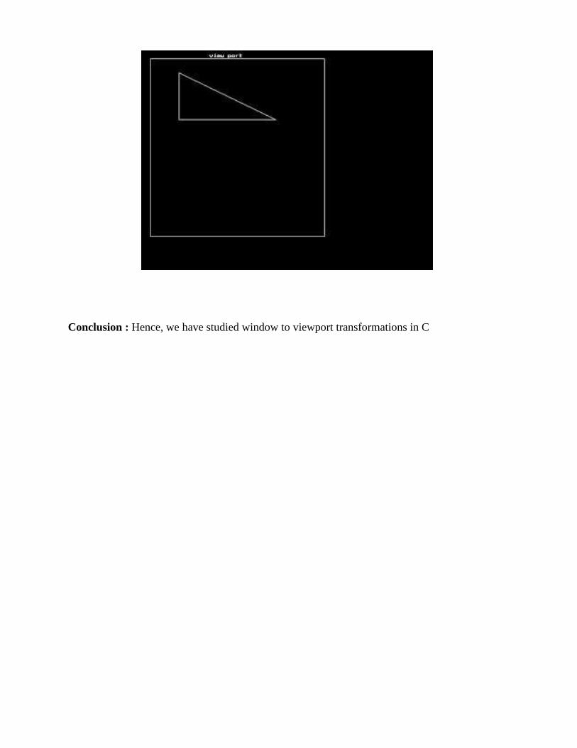
Conclusion : Hence, we have studied window to viewport transformations in C
Lab Exercise 10
Title-Program for Cohen Sutherland Line-clipping
algorithm
Objective:To study Cohen Sutherland line clipping algorithm.
Theory:
Program to implement the Cohen-Sutherland line-clipping algorithm. Make provision to specify
the input line, window for clipping and viewport for displaying the clipped image.
Algorithm at work:
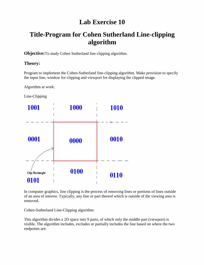
Line-Clipping
In computer graphics, line clipping is the process of removing lines or portions of lines outside
of an area of interest. Typically, any line or part thereof which is outside of the viewing area is
removed.
Cohen-Sutherland Line-Clipping algorithm:
This algorithm divides a 2D space into 9 parts, of which only the middle part (viewport) is
visible. The algorithm includes, excludes or partially includes the line based on where the two
endpoints are:
Both endpoints are in the viewport (bitwise OR of endpoints == 0): trivial accept.
Both endpoints are in the same part, which is not visible (bitwise AND of endpoints != 0):
trivial reject.
Both endpoints are in different parts: In case of this non trivial situation the algorithm finds one
of the two points that are outside the viewport (there is at least one point outside). The
intersection of the outpoint and extended viewport border is then calculated (i.e. with the
parametric equation for the line) and this new point replaces the outpoint. The algorithm repeats
until a trivial accept or reject occurs.
Steps for Cohen-Sutherland Algorithm
1. End-points pairs are checked for trivial acceptance or rejection using outcode (region code,
each of the 9 parts are assigned a 4 bit code indicating their location with respect to the window/
region of interest).
2. If not trivially accepted or rejected, divide the line segment into two at a clip edge;
3. Iteratively clipped by test trivial-acceptance or trivial-rejection, and divided into two segments
until completely inside or trivial-rejection.
// Program #include"stdio.h"
#include"conio.h"
#include"graphics.h"
void main()
{
int gd=DETECT, gm;
float i,xmax,ymax,xmin,ymin,x1,y1,x2,y2,m;
float start[4],end[4],code[4];
clrscr();
initgraph(&gd,&gm,"");
printf("\n\tPlease enter the bottom left co-ordinate of viewport: ");
scanf("%f %f",&xmin,&ymin);
printf("\n\tPlease enter the top right co-ordinate of viewport: ");
scanf("%f %f",&xmax,&ymax);
printf("\nPlease enter the co-ordinates for starting point of line: ");
scanf("%f %f",&x1,&y1);
printf("\nPlease enter the co-ordinates for ending point of line: ");
scanf("%f %f",&x2,&y2);
for(i=0;i <4;i++)
{
start[i]=0;
end[i]=0;
}
m=(y2-y1)/(x2-x1);
if(x1 <xmin) start[0]=1;

if(x1 >xmax) start[1]=1;
if(y1 >ymax) start[2]=1;
if(y1 <ymin) start[3]=1;
if(x2 <xmin) end[0]=1;
if(x2 >xmax) end[1]=1;
if(y2 >ymax) end[2]=1;
if(y2 <ymin) end[3]=1;
for(i=0;i <4;i++)
code[i]=start[i]&&end[i];
if((code[0]==0)&&(code[1]==0)&&(code[2]==0)&&(code[3]==0))
{
if((start[0]==0)&&(start[1]==0)&&(start[2]==0)&&(start[3]==0)&&(end[0]==0)&&(end[1]==0
)&&(end[2]==0)&&(end[3]==0))
{
cleardevice();
printf("\n\t\tThe line is totally visible\n\t\tand not a clipping candidate");
rectangle(xmin,ymin,xmax,ymax);
line(x1,y1,x2,y2);
getch();
}
else
{
cleardevice();
printf("\n\t\tLine is partially visible");
rectangle(xmin,ymin,xmax,ymax);
line(x1,y1,x2,y2);
getch();
if((start[2]==0)&&(start[3]==1))
{
x1=x1+(ymin-y1)/m;
y1=ymin;
}
if((end[2]==0)&&(end[3]==1))
{
x2=x2+(ymin-y2)/m;
y2=ymin;
}
if((start[2]==1)&&(start[3]==0))
{
x1=x1+(ymax-y1)/m;
y1=ymax;
}
if((end[2]==1)&&(end[3]==0))
{
x2=x2+(ymax-y2)/m;

y2=ymax;
}
if((start[1]==0)&&(start[0]==1))
{
y1=y1+m*(xmin-x1);
x1=xmin;
}
if((end[1]==0)&&(end[0]==1))
{
y2=y2+m*(xmin-x2);
x2=xmin;
}
if((start[1]==1)&&(start[0]==0))
{
y1=y1+m*(xmax-x1);
x1=xmax;
}
if((end[1]==1)&&(end[0]==0))
{
y2=y2+m*(xmax-x2);
x2=xmax;
}
clrscr();
cleardevice();
printf("\n\t\tAfter clippling:");
rectangle(xmin,ymin,xmax,ymax);
line(x1,y1,x2,y2);
getch();
}
}
else
{
clrscr();
cleardevice();
printf("\nLine is invisible");
rectangle(xmin,ymin,xmax,ymax);
}
getch();
closegraph();
}

Input:
Please enter the bottom left co-ordinate of viewport: 100 100
Please enter the top right co-ordinate of viewport: 400 400
Please enter the coordinates for starting point of line: 120 60
Please enter the coordinates for ending point of line: 350 450
Output:
Conclusion: Thus we have studied Line Clipping

Lab Exercise 11
Title-Program for polygon filling using flood fill
method.
Objective: : Implement Polygon filling algorithms [Flood-Fill Algorithm] in C.
Theory :
Polygon Filling : Approaches used to fill polygon
1 )Seed Fill Approaches 2 algorithms: Boundary Fill and Flood Fill works at the pixel level
suitable for interactive painting applications
2) Scan line Fill Approaches works at the polygon level better performance Flood fill, also called
seed fill, is an algorithm that determines the area connected to a given node in a multi-
dimensional array. It is used in the "bucket" fill tool of paint programs to fill connected,
similarly-colored areas with a different color, and in games such as Go and Minesweeper for
determining which pieces are cleared. When applied on an image to fill a particular bounded area
with color, it is also known as boundary fill.
#include stdio.h
#include conio.h
#include graphics.h
#include dos.h
void flood(int,int,int,int);
void main()
{
int gd,gm=DETECT;
clrscr();
detectgraph(&gd,&gm);
initgraph(&gd,&gm,”c:\\tc\\bgi”);
rectangle(50,50,100,100);
flood(55,55,12,0); getch();
}
void flood(int x,int y, int fill_col, int old_col)
{
if(getpixel(x,y)==old_col)
{
delay(10);
putpixel(x,y,fill_col);
flood(x+1,y,fill_col,old_col);
flood(x-1,y,fill_col,old_col);

flood(x,y+1,fill_col,old_col);
flood(x,y-1,fill_col,old_col);
}
}
Output :
Conclusion : Hence, we have studied Polygon filling algorithms [Flood-Fill Algorithm]

Lab Exercise 12
Title-Design an application in OpenGL
Objective : To study OpenGL transformation matrices and concatenation of transformation
Theory:
Related Topics: OpenGL Pipeline, OpenGL Projection Matrix, Homogeneous Coordinates
Overview
· OpenGL Transform Matrix
· Example: GL_MODELVIEW Matrix
· Example: GL_PROJECTION Matrix
Geometric data such as vertex positions and normal vectors are transformed via Vertex
Operation and Primitive Assembly operation in OpenGL pipeline before raterization
process.
OpenGL vertex transformation
Object Coordinates
It is the local coordinate system of objects and is initial position and orientation of objects before
any transform is applied. In order to transform objects, use glRotatef(), glTranslatef(), glScalef().
Eye Coordinates
It is yielded by multiplying GL_MODELVIEW matrix and object coordinates. Objects are
transformed from object space to eye space using GL_MODELVIEW matrix in OpenGL.
GL_MODELVIEW matrix is a combination of Model and View matrices ( ). Model transform
is to convert from object space to world space. And, View transform is to convert from world
space to eye space.

Program to draw a color cube and spin it using OpenGL transformation matrices.
Program Code:
#include<stdlib.h>
#include<GL/glut.h>
GLfloat vertices[][3]={{-1.0,-1.0,-1.0},{1.0,-1.0,-1.0},{1.0,1.0,-1.0},{-1.0,1.0,-1.0},{-1.0,-
1.0,1.0},{1.0,-1.0,1.0},{1.0,1.0,1.0},{-1.0,1.0,1.0}};
GLfloat normals[][3]={{-1.0,-1.0,-1.0},{1.0,-1.0,-1.0},{1.0,1.0,-1.0},{-1.0,1.0,-1.0},{-1.0,-
1.0,1.0},{1.0,-1.0,1.0},{1.0,1.0,1.0},{-1.0,1.0,1.0}};
GLfloat
colors[][3]={{0.0,0.0,0.0},{1.0,0.0,0.0},{1.0,1.0,0.0},{0.0,1.0,0.0},{0.0,0.0,1.0},{1.0,0.0,1.0},{
1.0,1.0,1.0},{0.0,1.0,1.0}};
void polygon(int a ,int b,int c, int d)
{
glBegin(GL_POLYGON);
glColor3fv(colors[a]);
glNormal3fv(normals[a]);
glVertex3fv(vertices[a]);
glColor3fv(colors[b]);
glNormal3fv(normals[b]);
glVertex3fv(vertices[b]);
glColor3fv(colors[c]);
glNormal3fv(normals[c]);
glVertex3fv(vertices[c]);
glColor3fv(colors[d]);
glNormal3fv(normals[d]);
glVertex3fv(vertices[d]);
glEnd();

}
void colorcube()
{
polygon(0,3,2,1);
polygon(2,3,7,6);
polygon(0,4,7,3);
polygon(1,2,6,5);
polygon(4,5,6,7);
polygon(0,1,5,4);
}
static GLfloat theta[]={0.0,0.0,0.0};
static GLint axis=2; void display()
{
glClear(GL_COLOR_BUFFER_BIT|GL_DEPTH_BUFFER_BIT);
glRotatef(theta[0],1.0,0.0,0.0);
glRotatef(theta[1],0.0,1.0,0.0);
glRotatef(theta[2],0.0,0.0,1.0);
colorcube();
glFlush();
glutSwapBuffers();
}
void spincube()
{
theta[axis]+=1.0;
if(theta[axis]>360.0)theta[axis]-=360.0;

glutPostRedisplay();
}
void mouse(int btn,int state,int x,int y)
{
if(btn==GLUT_LEFT_BUTTON&&state==GLUT_DOWN)axis=0;
if(btn==GLUT_MIDDLE_BUTTON&&state==GLUT_DOWN)axis=1;
if(btn==GLUT_RIGHT_BUTTON&&state==GLUT_DOWN)axis=2;
}
void myreshape(int w,int h)
{
glViewport(0,0,w,h);
glMatrixMode(GL_PROJECTION);
glLoadIdentity();
if(w<=h)
glOrtho(-2.0,2.0,-2.0*(GLfloat)h/(GLfloat)w,2.0*(GLfloat)h/(GLfloat)w,-10.0,10.0);
else
glOrtho(-2.0*(GLfloat)w/(GLfloat)h,2.0*(GLfloat)w/(GLfloat)h,-2.0,2.0,-10.0,10.0);
glMatrixMode(GL_MODELVIEW);
}
void main(int argc, char **argv)
{
glutInit(&argc,argv);
glutInitDisplayMode(GLUT_DOUBLE|GLUT_RGB|GLUT_DEPTH);
glutInitWindowSize(500,500);
glutInitWindowPosition(0,0);
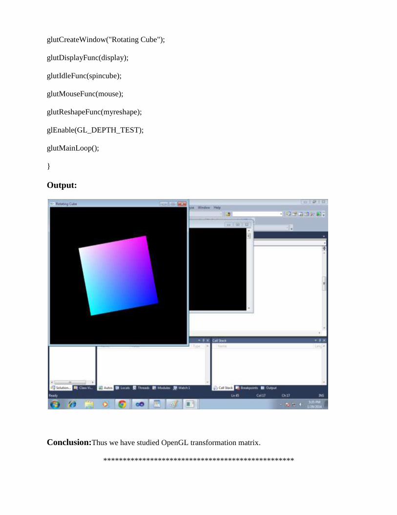
glutCreateWindow("Rotating Cube");
glutDisplayFunc(display);
glutIdleFunc(spincube);
glutMouseFunc(mouse);
glutReshapeFunc(myreshape);
glEnable(GL_DEPTH_TEST);
glutMainLoop();
}
Output:
Conclusion:Thus we have studied OpenGL transformation matrix.
*************************************************

3. Quiz on the subject:
4. Conduction of Viva –Voce Examinnations
Teacher should conduct oral exams of the students with full preparation. Normally, the
objective questions with guess are to be avoided. To make it meaningful, the questions
should be such that depth of the students in the subject is tested. Oral examinations are to be
conducted in cordial environment amongst the teachers taking the examination. Teachers
taking such examinations should not have ill thoughts about each other and courtesies should
be offered to each other in case of difference of opinion, which should be critically
suppressed in front of the students.
5. Evaluation and marking system: Basic honesty in the evaluation and marking system is absolutely essential and in the process
impartial nature of the evaluator is required in the examination system to become. It is a
primary responsibility of the teacher to see that right students who are really putting up lot of
hard work with right kind of intelligence are correctly awarded.
The marking patterns should be justifiable to the students without any ambiguity and teacher
should see that students are faced with just circumstances.


![[XLS] · Web viewRatnagiri Raigad Pune Parbhani Osmanabad Nashik Nandurbar Nanded Nagpur Latur Kolhapur Jalna Jalgaon Hingoli Gondia Gadchiroli Dhule Chandrapur Buldhana Bhandara](https://static.fdocuments.in/doc/165x107/5acc47517f8b9aad468c96fd/xls-viewratnagiri-raigad-pune-parbhani-osmanabad-nashik-nandurbar-nanded-nagpur.jpg)