
TP2072E
34
Transport Transports TP2072E Canada Canada Marine Marine DECK CARGO SAFETY CODE JANUARY 1974
-
Upload
anonymous-j3wout -
Category
Documents
-
view
214 -
download
0
description
TP related to loading of deck cargo
Transcript of TP2072E

Transport Transports TP2072E Canada Canada Marine Marine
DECK CARGO
SAFETY CODE JANUARY 1974

CANADA

CANADIAN MARINE TRANSPORTATION ADMINISTRATION
This code is a recommendation which has been developed by the Ministry of Transport in close consultation with representatives of the Canadian shipping industry. It states an agreed practice for promotion of ship safety in the stowage and carriage of deck cargoes and, for this purpose, has at annex I and II the relevant recommendations of the Inter-Governmental Maritime Consultative Organization, (IMCO).
W. A. O’Neil Deputy Administrator Marine Services

The recommendations contained in Annex I concerning stability data for passenger and cargo ships under 100 metres in length shall not supersede any Ministry of Transport regulation or any stability requirements contained in a vessel’s stability book approved by the Ministry of Transport.

2
CONTENTS
Foreword 3
Section 1 Application 3
Section 2 Stability 3
Section 3 Securing of Deck Cargo 4
Section 4 Vessels fitted with side, bow or stern loading doors 4
Section 5 Safe Access 4
Section 6 Stress on Deck 4
Section 7 Inspection 5
Section 8 Records of Office 5
Annex I Recommendation On Intact Stability For Passenger and Cargo Ships Under 100 Metres in Length 6
Annex II Recommendation on the Safe Stowage and Securing of Containers on Deck on Vessels Which are Not Specially Fitted for the Purpose of Carrying Containers 31

3
DECK CARGO SAFETY CODE 1. Application 1.1 This code applies to the loading and carriage of any cargo loaded on any exposed
deck, other than timber dock cargo, on every ship that is at any place in Canada. 2. Stability 2.1 The Master should ensure that cargo shall not be loaded on the deck of a ship,
unless that ship has an initial margin of stability sufficient to permit the maintenance of a safe margin of positive stability throughout the loading operation and voyage.
2.2 The Master should ensure that no cargo shall be loaded into, or discharged from,
the lower decks while deck cargo is on board except when the Master has satisfied himself that the ship will retain safe positive stability throughout the cargo handling operation.
2.3 If at any time during cargo operations an abnormal list develops such list shall be
corrected forthwith. 2.4 If a ship develops an angle of loll the Master shall cease all cargo operations
forthwith until corrective measures have been determined and carried out (including, if necessary, the discharge of deck cargo, the loading of lower compartments or the filling of double bottom tanks) as may be required to return the ship to a normal safe condition of positive stability without loll.
2.5 The Master should determine the ship’s stability for the worst voyage condition
taking into account the free surface effect of liquids carried on board the vessel. 2.6 Ships under 100 metres, (328 feet), in length should be provided with the stability
information and direction as recommended by Resolution A.167 (ES-IV) of the Inter-Governmental Maritime Consultative Organization (IMCO) at Annex I. to enable the Master to calculate the minimum and maximum metacentric heights and a substantial range and area associated with the righting lever curve.
2.7 In all ships the Master should be guided by the ship’s stability documents in regard
to the calculation of minimum and maximum metacentric heights and of substantial range and area associated with the righting lever curve.

4
3. Securing of Deck Cargo 3.1 The Master should ensure that cargo stowed on any exposed deck of a ship shall be
stowed or secured so as to prevent its movement. When securing is necessary it should be carried out prior to the ship being exposed to any conditions likely to produce movement or shift of the deck cargo.
3.2 Vessels which are not normally fitted with securing arrangements, generally found in
special purpose container vessels, should give particular attention to the stowage and securing of containers when carried on deck. Masters should be guided by the recommendations of the Inter-Governmental Maritime Consultative Organization in Annex II.
4. Vessels fitted with side, bow or stern loading doors 4.1 The Master should ensure that cargo shall not be loaded on, or discharged from,
any exposed deck of a ship fitted with side, bow or stern loading doors unless such doors are secured ready for sea, except as provided in Section 4.2.
4.2 Cargo may be loaded on, or discharged from, an exposed deck of a ship with side,
bow or stern loading doors open when special safety precautions are observed. Such precautions should include routine procedures carried out by trained personnel, ensuring an upright condition, safe trim and a minimum freeboard below the door sill consistent with the designed safety criteria of that vessel. Due consideration shall be made of the prevailing sea, weather or other special conditions.
5. Safe Access 5.1 The Master should ensure that the deck cargo is stowed and secured in such a
manner as to provide clear all round visibility from the navigation bridge and to give safe and satisfactory gangway access to all accommodation, working and machinery spaces, life-saving and firefighting equipment and other equipment and areas to which access is necessary for the safe working of the ship at sea and in port. He has the responsibility under the Safe Working Practices Regulations to provide guard rails, lines or other protection, around open hatchways and open spaces in the deck stow.
6. Stress on Deck 6.1 The stow of the deck cargo should be so arranged that the stress exerted by the
cargo does not exceed the designed maximum permissible stress on the deck areas or hatches upon which it is stowed.
5
7. Inspection 7.1 In accordance with the provisions of the Canada Shipping Act a Port Warden shall,
upon request of the Master or Agent, board a ship which is about to load, or has on board, a deck cargo, to survey the ship’s stability condition and the arrangements made for securing the deck cargo add providing safe gangway access and guard rails.
7.2 On the request of a port warden conducting a survey in accordance with Section 7.
1, he shall be supplied with a calculation or other satisfactory declaration of proof of the ship’s stability, signed by the Master.
8. Records of Office 8. 1 The details of any survey or inspection of a vessel made in accordance with this
code shall be entered in the records of office of the Port Warden of which copies under seal shall be available to interested parties, as provided for in the Canada Shipping Act.

6
ANNEX I
IMCO
RECOMMENDATION ON INTACT STABILITY FOR PASSENGER AND CARGO SHIPS UNDER 100 METRES IN LENGTH
FOREWORD Stability is one of the most important safety features of ships, and in particular of small ships which tend to suffer from insufficient stability which could lead to capsizing the vessel and loss of the crew. It is, therefore, essential to design a ship with adequate stability and to maintain it in all conditions of loading during its operation. The International Conference on Safety of Life at Sea, 1960, recognizing the importance of the stability of ships, recommended that IMCO should undertake studies on intact stability of passenger ships, cargo ships and fishing vessels, with a view to formulating such international standards as may appear necessary. In pursuance of the above recommendation, the Inter-Governmental Maritime Consultative Organization established in 1960 the Sub-Committee on Sub-division and Stability which was charged, among others, with the task of studying the intact stability of passenger ships and cargo ships. As a result of the Sub-Committee’s comprehensive studies on existing national requirements, on results of analyses of intact stability casualty records and on stability calculations of ships which have operated successfully, a Recommendation on Intact Stability for Passenger and Cargo Ships under 100 metres in length was drawn up. This Recommendation was approved by the Maritime Safety Committee in March 1968 and adopted by the Assembly of the Organization at its fourth extraordinary session in November 1968. By Resolution A. 167(ES.IV) the Assembly invited all governments concerned to take steps to give effect to the Recommendation as soon as possible unless they are fully satisfied that their national stability requirements supported by long operating experience already ensure adequate stability for particular types and sizes of ships. The Assembly at the same time requested the Maritime Safety Committee to continue the study on this subject and to develop improved stability criteria.

7
As regards fishing vessels, due to their special constructional features and specific conditions under which they operate, a separate recommendation on intact stability of fishing vessels has been formulated (Assembly Resolution A.168(ES.IV). This recommendation is issued as a separate IMCO publication. The Organization is continuing its studies on the stability criteria, paying particular attention to the effect of external forces on stability. Studies on stability of special types of ships, apart from fishing vessels, such as ships carrying timber deck cargo, container ships, hydrofoil boats and air cushion vehicles, as well as drilling rigs and production platforms, are also in progress.

8
CONTENTS Page Recommendation on Intact Stability for Passenger and Cargo Ships under 100 Metres in Length. . . . . . . . . . . . . . . . . . . . . . . . . . . . . . . . . .
9
1. Scope . . . . . . . . . . . . . . . . . . . . . . . . . . . . . . . . . . . . . . . . . . . . . . 9 2. General Precautions against Capsizing . . . . . . . . . . . . . . . . . . . 9 3. Calculation of Stability Curves . . . . . . . . . . . . . . . . . . . . . . . . . . . . 9 4. Assessment of Compliance with Criteria . . . . . . . . . . . . . . . . . . . 9 5. Recommended Criteria . . . . . . . . . . . . . . . . . . . . . . . . . . . . . . . . . 10 6. Inclining Test . . . . . . . . . . . . . . . . . . . . . . . . . . . . . . . . . . . . . . . . . 12 7. Stability Information . . . . . . . . . . . . . . . . . . . . . . . . . . . . . . . . . . . 12 Appendix I Calculation of Stability Curves . . . . . . . . . . . . . . . . . . . . . . . . . . 14 1. General . . . . . . . . . . . . . . . . . . . . . . . . . . . . . . . . . . . . . . . . . . . . . 14 2. Superstructures, Deckhouses, etc. , which may be taken into
Account . . . . . . . . . . . . . . . . . . . . . . . . . . . . . . . . . . . . . . . . . . . . .
14 3. Effect of Liquid in Tanks . . . . . . . . . . . . . . . . . . . . . . . . . . . . . . . . 15 4. Effect of Timber Deck Cargo . . . . . . . . . . . . . . . . . . . . . . . . . . . . 16 Appendix II Standard Conditions of Loading to be Examined 1. Loading Conditions . . . . . . . . . . . . . . . . . . . . . . . . . . . . . . . . . . . . 19 2. Assumptions for Calculating Loading Conditions . . . . . . . . . . . . . 20 Appendix III Memorandum to Administrations on an Approximate
Determination of Ship’s Stability by Means of the Rolling Period Tests (for ships up to 70 m. in length)
Annex Suggested Form of Guidance to the Master on an Approximate
Determination of Ship’s Stability by Means of the Rolling Period Test . . . . . . . . . . . . . . . . . . . . . . . . . . . . . . . . . . .
28 1. Introduction . . . . . . . . . . . . . . . . . . . . . . . . . . . . . . . . . . . . . . . . . . 28 2. Test Procedure . . . . . . . . . . . . . . . . . . . . . . . . . . . . . . . . . . . . . . . 28 3. Determination of the Initial Stability . . . . . . . . . . . . . . . . . . . . . . . . 29 4. Limitations to the Use of this Method . . . . . . . . . . . . . . . . . . . . . 30

9
RECOMMENDATION ON INTACT STABILITY FOR PASSENGER AND CARGO SHIPS UNDER 100 METRES IN LENGTH
1. Scope 1.1. The provisions given hereunder are recommended for new decked sea-going
passenger and cargo ships (other than fishing vessels) under 100 metres in length. 1.2. Administrations are invited to adopt, for all conditions of loading, the stability criteria
given in 5, unless they are satisfied that operating experience justifies departures therefrom.
2. General Precautions against Capsizing 2.1. Compliance with the stability criteria does not ensure immunity against capsizing
regardless of the circumstances or absolve the master from his responsibilities. Masters should therefore exercise prudence and good seamanship having regard to the season of the year, weather forecasts and the navigational zone and should take the appropriate action as to speed and course warranted by the prevailing circumstances.
2.2. Care should be taken that the cargo allocated to the ship is capable of being
stowed so that compliance with the criteria can be achieved. If necessary the amount should be limited to the extent that ballast weight may be required.
2.3. Before a voyage commences care should be taken to ensure that the cargo and
sizeable pieces of equipment have been properly stowed or lashed so as to minimize the possibility of both longitudinal and lateral shifting while at sea, under the effect of acceleration caused by rolling and pitching.
3. Calculation of Stability Curves
The methods and procedures employed for calculating stability righting arms should be in accordance with Appendix I, and the degree of accuracy obtained should be acceptable to the Administration.
4. Assessment of Compliance with Criteria 4.1. For the purpose of assessing in general whether the criteria are met, stability
curves should be drawn for the main loading conditions intended by the owner in respect of the ship’s operations.

10
4.2. If the owner does not supply sufficiently detailed information regarding such loading conditions, calculations should be made for the standard conditions given in Appendix II.
4.3. In all cases calculations should be based on the assumptions shown in
Appendix II. 5. Recommended Criteria 5.1. The following criteria are recommended for passenger and cargo ships:
(a) The area under the righting lever curve (GZ curve) should not be less than 0.055 metre-radians up to θ = 30° angle of heel and not less than 0.09 metre-radians up to θ = 40° or the angle of flooding θf if this angle is less than 40°.
Additionally, the area under the righting lever curve (GZ curve) between the angles of heel of 30° and 40° or between 30° and θf, if this angle is less than 40°, should not be less than 0.03 metre-radians.
(b) The righting lever GZ should be at least 0.20m. at an angle of heel equal to or
greater than 30° (c) The maximum righting arm should occur at an angle of heel preferably
exceeding 30° but not less than 25° (d) The initial metacentric height GM0 should not be less than 0. 15m.
5.2. For ships loaded with timber deck cargoes and provided that the cargo extends
longitudinally between superstructures transversely for the full beam of ship after due allowance for a rounded gunwale not exceeding 4 per cent of the breadth of the ship and/or securing the supporting uprights and which remains securely fixed at large angle of heel, an Administration may apply the following criteria in substitution for criteria given in 5.1 above:
(a) the area under the righting lever (GZ curve) should not be less than
0.08 metre-radians up to θ = 40°or the angle of flooding if this angle is less than 40.

11
*θf is an angle of heel at which openings in the hull, superstructures or deckhouses which cannot be closed weathertight immerse. In applying this criterion, small openings through which progressive flooding cannot take place need not be considered as open.
(b) The maximum value of the righting lever (GZ) should be at least 0.25 m. (c) at all times during a voyage the metacentric height GM0 should be positive
after correction for the free surface effects of liquid in tanks, and, where appropriate, the absorption of water by the deck cargo and/or ice accretion on the exposed surfaces. Additionally, in the departure condition the metacentric height should be not less than 0.10 m.
5.3. The following additional criteria are recommended for passenger ships:
(a) The angle of heel on account of crowding of passengers to one side as defined in Appendix II 2. (9) should not exceed 10°.
(b) The angle of heel on account of turning should not exceed 10° when
calculated using the following formula:
MR = 0.02 V2 o ∆ (KG - d) L 2 where:
MR = heeling moment in metre-tons, Vo = service speed in m./sec., L = length of ship at waterline in m., ∆ = displacement in metric tons, d = mean draught in m. , KG = height of centre of gravity above keel in m.
5.4. The criteria mentioned in 5.1 and 5.2 fix minimum values, but no maximum values
are recommended. It is advisable to avoid excessive values, since these might lead to acceleration forces which could be prejudicial to the ship, its complement, its equipment and to the safe carriage of the cargo.
5.5. Where anti-rolling devices are installed in a ship the Administration should be
satisfied that the above criteria can be maintained when the devices are in operation.

12
5.6. A number of influences such as beam wind on ships with large windage area, icing of topsides, water trapped on deck, rolling characteristics, following seas, etc., adversely affect stability and the Administration is advised to take these into account so far as is deemed necessary.
5.7. Regard should be paid to the possible adverse effects on stability where certain
bulk cargoes are carried. In this connection attention should be paid to the Code of Safe Practice for Bulk Cargoes. Ships carrying grain in bulk should comply with the criteria mentioned in 5.1 in addition to the stability requirements in Chapter VI of the International Convention for the Safety of Life at Sea, 1960.
6. Inclining Test 6.1. When construction is finished, each ship should undergo an inclining test, actual
displacement and co-ordinates of the centre of gravity being determined for the light ship condition.
6.2. The Administration may allow the inclining test of an individual ship to be dispensed
with, provided basic stability data are available from the inclining test of a sister ship.
7. Stability Information 7.1. The master of any ship to which the present Recommendation applies should
receive information which will enable him to assess with ease and certainty the stability of his ship in different service conditions. A duplicate of this information should be communicated to the Administration.
7.2. Stability information should comprise:
(i) Stability characteristics of typical loading conditions; (ii) Information in the form of tables or diagrams which will enable the master to
assess the stability of his ship and verify whether it is sufficient in all loading conditions differing from the standard ones. This information should include, in particular, a curve or table giving, as a function of the draughts, the required initial metacentric height GM0 (or any other stability parameter) which ensures that the stability is in compliance with the criteria given in 5.1 above;
(iii) Information on the proper use of anti-miling devices if these are installed in
the ship;

13
(iv) Additionally, information enabling the ship’s master to determine the initial metacentric height GM0 by means of rolling test as described in the Annex to the Memorandum to Administrations reproduced at Appendix III would be desirable;
(v) Notes on the corrections to be made to the initial metacentric height GM0 to
take account of free surface liquids.
(vi) For ships carrying timber deck cargoes the Administration may deem it necessary that the master be given information setting out the changes in deck cargo from that shown in the loading conditions, when the permeability of the deck cargo is significantly different from 25 per cent.
(vii) For ships carrying timber deck cargoes conditions should be shown
indicating the maximum permissible amount of deck cargo having regard to the lightest stowage rate likely to be met in service.

14
APPENDIX I
CALCULATION OF STABILITY CURVES
1. General
(1) Hydrostatic and stability curves should normally be prepared on a designed trim basis. However, where the operating trim or the form and arrangement of the ship are such that change in trim has an appreciable effect on righting arms, such change in trim should be taken into account.
(2) The calculations should take into account the volume to the upper surface of
the deck sheathing. In the case of wood ships the dimensions should be taken to the outside of the hull planking.
2. Superstructures, Deckhouses, etc., which may be taken into Account
(3) Enclosed superstructures complying with Regulation 3(10)(b) of the 1966 Load Line Convention may be taken into account.
(4) The second tier of similarly enclosed superstructures may also be taken into
account. (5) Deckhouses on the freeboard deck may be taken into account, provided that
they comply with the conditions for enclosed superstructures laid down in Regulation 3(10)(b) of the 1966 Load Line Convention.
(6) Where deckhouses comply with the above conditions, except that no
additional exit is provided to a deck above, such deckhouses should not be taken into account; however, any deck openings inside such deckhouses shall be considered as closed even where no means of closure are provided.
(7) Deckhouses, the doors of which do not comply with the requirements of
Regulation 12 of the 1966 Load Line Convention, should not be taken into account; however, any deck openings inside the deckhouse are regarded as closed where their means of closure comply with the requirements of Regulations 15, 17 or 18 of the 1966 Load Line Convention.
(8) Deckhouses on decks above the freeboard deck should not be taken into
account, but openings within them may be regarded as closed.

15
(9) Superstructures and deckhouses not regarded as enclosed can, however, be taken into account in stability calculations up to the angle at which their openings are flooded. (At this angle, the statical stability curve should show one or more steps, and in subsequent computations the flooded space should be considered non-existent.)
(10) In cases where the ship would sink due to flooding through any openings, the
stability curve should be cut short at the corresponding angle of flooding and the ship should be considered to have entirely lost her stability.
(11) Small openings such as those for passing wires or chains, tackle and
anchors, and also holes of scuppers, discharge and sanitary pipes should not be considered as open if they submerge at an angle of inclination more than 30°. If they submerge at an angle of 30°or less, these openings should be assumed open if the Administration considers this to be a source of significant flooding.
(12) Trunks may be taken into account, Hatchways may also be taken into
account having regard to the effectiveness of their closures. 3. Effect of Liquid in Tanks
(13) For all conditions, the initial metacentric height and the stability curves should be corrected for the effect of free surfaces of liquids in tanks in accordance with the following assumption:
(i) Tanks which are taken into consideration when determining the effect
of liquids on the stability at all angles of inclination should include single tanks or combinations of tanks for each kind of liquid (including those for water ballast) which according to the service conditions can simultaneously have free surface;
(ii) For the purpose of determining this free surface correction, the tanks
assumed slack should be those which develop the greatest free surface moment, Mf.s. at a 30° inclination, when in the 50 per cent full condition;
(iii) the value of Mf.s. for each tank may be derived from the formula:
Mf.s. = vb γk δ
16
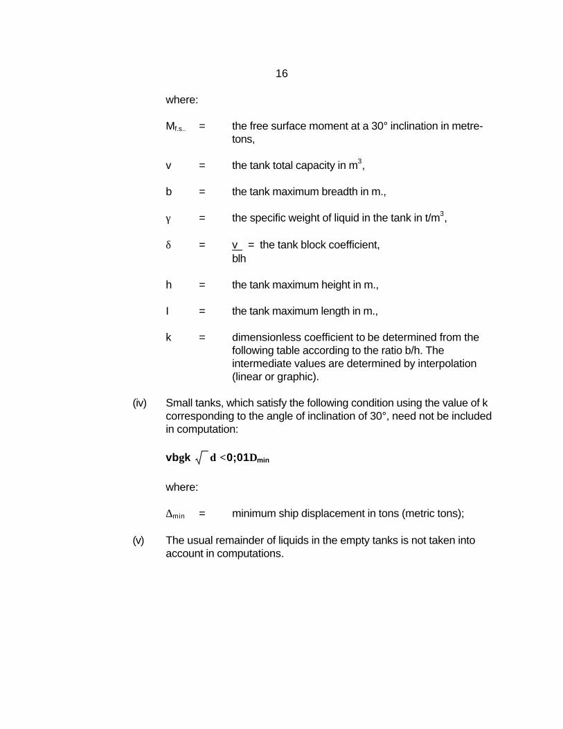
where: Mf.s.. = the free surface moment at a 30° inclination in metre-
tons, v = the tank total capacity in m3,
b = the tank maximum breadth in m., γ = the specific weight of liquid in the tank in t/m3, δ = v = the tank block coefficient,
blh
h = the tank maximum height in m., I = the tank maximum length in m., k = dimensionless coefficient to be determined from the
following table according to the ratio b/h. The intermediate values are determined by interpolation (linear or graphic).
(iv) Small tanks, which satisfy the following condition using the value of k corresponding to the angle of inclination of 30°, need not be included in computation:
vbγk δ <0;01∆min where: ∆min = minimum ship displacement in tons (metric tons);
(v) The usual remainder of liquids in the empty tanks is not taken into
account in computations.

17
4. Effect of timber deck cargo
In the case of ships carrying timber deck cargoes the Administration may allow account to be taken of the buoyancy of the deck cargo assuming that such cargo has a permeability of 25 per cent of the volume occupied by the cargo. Additional curves of stability may be required if the Administration considers it necessary to investigate the influence of different permeabilities and/or assumed effective height of the deck cargo.
(1) Where there is no limiting superstructure at the after end, the timber deck
cargo shall extend at least to the after end of the aftermost hatchway.

18
TABLE OF VALUES OR COEFFICIENT ‘K’ OR CALCULATING FREE SURFACE CORRECTIONS
k = sin δ (1 + tan2 δ) x b/h 12 2
k = cos θ (1 + tan θ) –cos θ2 (1 + cot2δ) 8 b/h 12(b/h) 2
where cot θ ≥b/h where cot θ ≤b/h

19
APPENDIX II
STANDARD CONDITIONS OF LOADING TO BE EXAMINED 1. Loading Conditions
The standard loading conditions referred to in 4.2 of the Recommendation are as follow:
(1) Passenger ship
(i) ship in the fully loaded departure condition with full stores and fuel and
with the full number of passengers with their luggage; (ii) ship in the fully loaded arrival condition, with the full number of
passengers and their luggage but with only 10 per cent stores and fuel remaining;
(iii) ship without cargo, but with full stores and fuel and the full number of
passengers and their luggage; (iv) ship in the same condition as at (iii) above but with only 10 per cent
stores and fuel remaining.
(2) Cargo ship
(i) ship in the fully loaded departure condition with cargo homogeneously distributed throughout all cargo spaces and with full stores and fuel;
(ii) ship in the fully loaded arrival condition with cargo homogeneously
distributed throughout all cargo spaces and with 10 per cent stores and fuel remaining;
(iii) ship in ballast in the departure condition, without cargo but with full
stores and fuel; (iv) ship in ballast in the arrival condition, without cargo and with 10 per
cent stores and fuel remaining.

20
(3) Cargo ships intended to carry deck cargoes:
(1) ship in the fully loaded departure condition with cargo homogeneously distributed in the holds and with cargo specified in extension and weight on deck, with full stores and fuel;
(2) ship in the fully loaded arrival condition with cargo homogeneously
distributed in holds and with a cargo specified in extension and weight on deck, with 10 per cent stores and fuel.
2. Assumptions for Calculating Loading Conditions
(1) For fully loaded conditions mentioned in 1(2)(i),2(ii), 3(i) and 3(ii) of this Appendix if a dry cargo ship has tanks for liquid cargo, the effective deadweight in the loading conditions therein described should be distributed according to two assumptions, i.e. (i) cargo tanks full, and (ii) cargo tanks empty.
(2) In conditions mentioned in 1.(I) and (2)(i)of this Appendix, it should be
assumed that the ship is loaded to her subdivision load line or summer load line, or if intended to carry a timber deck cargo, to the summer timber load line with water ballast tanks empty.
(3) If in any loading condition water ballast is necessary, additional diagrams
should be calculated taking into account the water ballast. Its quantity and disposition should be stated.
(4) In all cases the cargo in holds is assumed to be fully homogeneous unless
this condition is inconsistent with the practical service of the ship. (5) In all cases when deck cargo is carried a realistic stowage wieght should be
assumed and stated, including the height of cargo. (6) Where timber deck cargoes are carried, the amount of cargo and ballast
should correspond to the worst service condition in which all the relevant stability criteria in Section 5 are met. In the arrival conditions it should be assumed that the weight of the deck cargo has increased by 10 per cent due to water absorption.
(7) When timber deck cargoes are carried and it is anticipated that some
formation of ice will take place an allowance should be made in the arrival condition for the additional weight.

21
(8) A weight of 75 kg. should be assumed for each passenger except that this value may be reduced to not less than 60 kg. where this can be justified. In addition the weight and distribution of the luggage should be determined by the Administration.
(9) The height of the centre of gravity for passengers should be assumed equal
to:
(i) 1.0 metre above deck level for passengers standing upright. Account may be taken, if necessary, of camber and sheer of deck;
(ii) 0.30 metre above the seat in respect of seated passengers.
(10) Passengers and luggage should be considered to be in the spaces normally
at their disposal, when assessing compliance with the criteria at 5.1 (a), (b), (c) and (d) of the Recommendation.
(11) Passengers without luggage should be considered as distributed to produce
the most unfavourable combination of passenger heeling moment and/or initial metacentric height, which may be obtained in practice, when assessing compliance with the criteria at 5,2(a) and (b) of the Recommendation respectively. In this connection it is anticipated that a value higher than 4 persons per square metre will not be necessary.
22
APPENDIX III
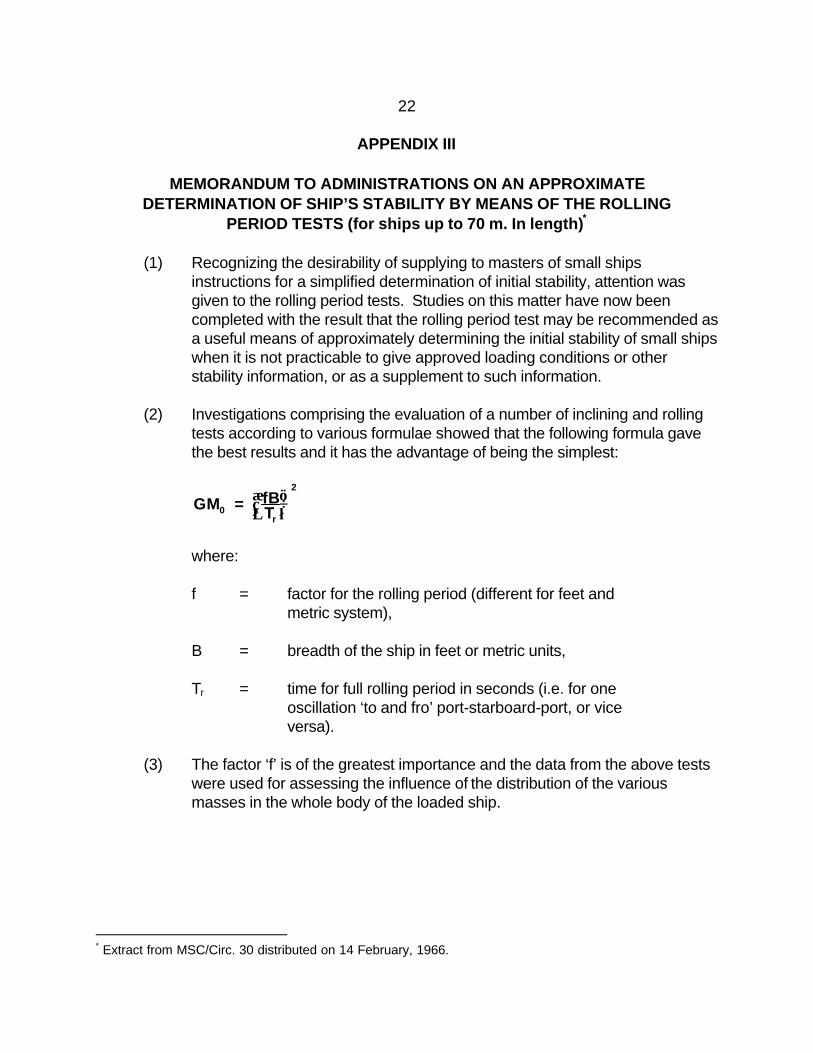
MEMORANDUM TO ADMINISTRATIONS ON AN APPROXIMATE DETERMINATION OF SHIP’S STABILITY BY MEANS OF THE ROLLING
PERIOD TESTS (for ships up to 70 m. In length)*
(1) Recognizing the desirability of supplying to masters of small ships instructions for a simplified determination of initial stability, attention was given to the rolling period tests. Studies on this matter have now been completed with the result that the rolling period test may be recommended as a useful means of approximately determining the initial stability of small ships when it is not practicable to give approved loading conditions or other stability information, or as a supplement to such information.
(2) Investigations comprising the evaluation of a number of inclining and rolling
tests according to various formulae showed that the following formula gave the best results and it has the advantage of being the simplest:
GM = fBT 0
r
2
where:
f = factor for the rolling period (different for feet and metric system), B = breadth of the ship in feet or metric units, Tr = time for full rolling period in seconds (i.e. for one oscillation ‘to and fro’ port-starboard-port, or vice versa).
(3) The factor ‘f’ is of the greatest importance and the data from the above tests
were used for assessing the influence of the distribution of the various masses in the whole body of the loaded ship.
* Extract from MSC/Circ. 30 distributed on 14 February, 1966.

23
(4) For coasters of normal size (excluding tankers), the following average values were observed:
(a) empty ship or ship metric system feet system carrying ballast f ~ 0.88 f ~ 0.49 (b) ship full loaded and with
liquids in tanks comprising the following percentage of the total load on board (i. e.cargo, liquids, stores. etc. )-
1. 20 per cent of total load.... f ~ 0.78 f ~ 0.435 2. 10 per cent of total load.... f ~ 0.75 f ~ 0.415 3. 5 per cent of total load...... f ~ 0.73 f ~ 0.405
The stated values are mean values. Generally, observed f-values were within 0.05 of those given above.
(5) These f-values were based upon a series of limited tests and, therefore,
Administrations should re-examine these in the light of any different circumstances applying to their own ships.
(6) It must be noted that the greater the distance of masses from the rolling axis,
the greater the rolling coefficient will be.
Therefore it can be expected that:
- the rolling coefficient for an unloaded ship, i.e. for a hollow body, will be higher than for a loaded ship;
- the rolling coefficient for a ship carrying a great amount of
bunkers and ballast-both groups are usually located in the double bottom, i.e. far away from the rolling axis-will be higher than that of the same ship having an empty double bottom.
(7) The above recommended rolling coefficients were determined by tests with
vessels in port and with their consumable liquids at normal working levels; thus, the influences exerted by the vicinity of the quay, the limited depth of water and the free surfaces of liquids in service tanks are covered.

24
(8) Experiments have shown that the results of the rolling test method get increasingly less reliable the nearer they approach GM-values of 0.20 m. and below.
(9) For the following reasons, it is not generally recommended that results be
obtained from rolling oscillations taken in a seaway:
(a) Exact coefficients for tests in open waters are not available. (b) The rolling periods observed may be not free oscillations but forced
oscillations due to seaway. (c) Frequently, oscillations are either irregular or only regular for too short
an interval of time to allow accurate measurements to be observed. (d) Specialized recording equipment is necessary.
(10) However, sometimes it may be desirable to use the vessel’s period of roll as a means of approximately judging the stability at sea. If this is done, care should be taken to discard readings which depart appreciably from the majority of other observations. Forced oscillations corresponding to the sea period and differing from the natural period at which the vessel seems to move should be disregarded. In order to obtain satisfactory results, it may be necessary to select intervals when the sea action is least violent, and it may be necessary to discard a considerable number of observations.
(11) In view of the foregoing circumstances, it needs to be recognized that the
determination of the stability by means of the rolling test in disturbed waters should only be regarded as a very approximate estimation.
(12) The formula given in paragraph (2) can be reduced to:
GM = FT0
r2
and the Administration should determine the F value(s) for each vessel.
(13) The determination of the stability can be simplified by giving the master
permissible rolling periods, in relation to the draughts, for the appropriate value(s) of F considered necessary.
25
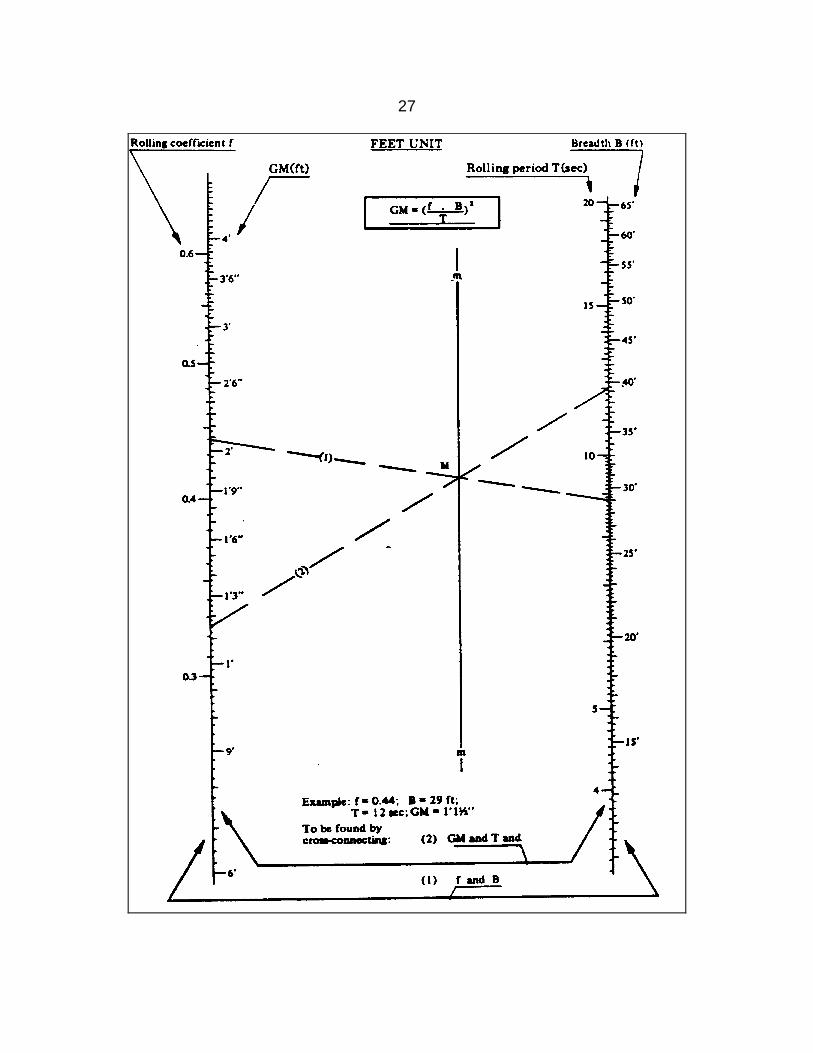
(14) The initial stability may also be more easily determined graphically by using one of the attached sample nomograms for feet and/or metric units as described below:
(a) The values for B and f are marked in the relevant scales and
connected by a straight (1). This straight line instersects the vertical line (mm) in the point (M).
(b) A second straight line (2) which connects this point (M) and the point
on the Tr scale corresponding with the determined rolling period, intersects the GM scale at the requested value.
(15) The Appendix shows an example of a recommended form in which these
instructions might be presented by each Administration to the Masters. It is considered that each Administration should recommend the F-value or values to be used.

26
27

28
ANNEX
Suggested Form of Guidance to the Master on an Approximate Determination of Ship’s Stability by Means of the
Rolling Period Test 1. Introduction
(1) If the following instructions are properly carried out this method allows reasonably quick and accurate estimation of the metacentric height, which is measure of the ship’s stability.
(2) The method depends upon the relationship between the metacentric height
and the rolling period in terms of the extreme breadth of the vessel. 2. Test Procedure
(3) The rolling period required is the time for one complete oscillation of the vessel and to ensure the most accurate results in obtaining this value the following precautions should be observed:
(a) The test should be conducted with the vessel in harbour, in smooth
water with the minimum interference from wind and tide. (b) Starting with the vessel at the extreme end of a roll to one side (say
port) and the vessel about to move towards the upright, one complete oscillation will have been made when the vessel has moved right across to the other extreme side (i.e. starboard) and returned to the original starting point and is about to commence the next roll.
(c) By means of a stop-watch, the time should be taken for not less than
about five of these complete oscillations; the counting of these oscillations should begin when the vessel is at the extreme end of a roll. After allowing the roll to completely fade way, this operation should be repeated at least twice more. If possible, in every case the same number of complete oscillations should be timed to establish that the readings are consistent, i.e. repeating themselves within reasonable limits. Knowing the total time for the total number of oscillations made, the mean time for one complete oscillation can be calculated.

29
(d) The vessel can be made to roll by rhythmically lifting up and putting down a weight as far off middle-line as possible; by pulling on the mast with a rope; by people running athwartships in unison; or by any other means. However, and this is most important, as soon as this forced rolling has commenced the means by which it has been induced must be stopped and the vessel allowed to roll freely and naturally. If rolling has been induced by lowering or raising a weight it is preferable that the weight is moved by a dockside crane. If the ship’s own derrick is used, the weight should be placed on the deck, at the middle-line, as soon as the rolling is established.
(e) The timing and counting of the oscillations should only begin when it is
judged that the vessel is rolling freely and naturally and only as much as is necessary to accurately count these oscillations.
(f) The mooring should be slack and the vessel “breasted off” to avoid
making any contact during its rolling. To check this, and also to get some idea of the number of complete oscillations that can be reasonably counted and timed, a preliminary rolling test should be made before starting to record actual times.
(g) Care should be taken to ensure that there is a reasonable clearance
of water under the keel and at the sides of the vessel. (h) Weights of reasonable size which are liable to swing (e.g. a lifeboat),
or liable to move (e.g. a drum), should be secured agains such movement The free surface effects of slack tanks should be kept as small as is practicable during the test and the voyage.
3. Determination of the Initial Stability
(4) Having calculated the period for one complete oscillation, say T seconds, the metacentric height GM0 can be calculated from the following formula:
GM = FT0 2
where F is ... [to be determined for each particular vessel by the Administration]

30
(5) The calculated value of GM0 should be equal to or greater than the critical value which is [to be determined for each particular vessel by the Administration].
4. Limitations to the Use of this Method
(6) A long period of roll corresponding to a GM0 of 0.20 m. or below, indicates a condition of low stability. However, under such circumstances, accuracy in determination of the actual value of GM0 is reduced.
(7) If, for some reason, these rolling tests are carried out in open, deep but
smooth waters, inducing the roll, for example, by putting over the helm, then the GM0 calculated by using the method and coefficient of paragraph (3) above should be reduced by figure to be estimated by the Administration to obtain the final answer.
(8) The determination of stability by means of the rolling test in disturbed waters
should only be regarded as a very approximate estimation. If such test is performed, care should be taken to discard readings which depart appreciably from the majority of other observations. Forced oscillations corresponding to the sea period and differing from the natural period at which the vessel seems to move should be disregarded. In order to obtain satisfactory results, it may be necessary to select intervals when the sea action is least violent, and it may be necessay to discard a considerable number of observations.

31
ANNEX II
IMCO
RECOMMENDATION ON
THE SAFE STOWAGE AND SECURING OF CONTAINERS ON DECK ON VESSELS WHICH ARE NOT SPECIALLY DESIGNED AND
FIMD FOR THE PURPOSE OF CARRYING CONTAINERS THE MARITIME SAFETY COMMITTEE RECOMMENDS: (a) Containers carried on deck or on hatches should be stowed preferably in a fore
and aft direction; (b) The containers should be stowed so that they do not extend over the vessel’s side.
Adequate supports should be provided when containers overhang hatches or deck structures;
(c) The containers should be stowed and secured so as to permit safe access for
personnel in the necessary working of the vessel; (d) All containers should be effectively secured preferably at the bottom comers in a
way which will guard against sliding. Restraint against upping should be effected by securing the top or bottom corners as may be practicable;
(e) Containers carried on deck or hatches should be carried one high unless the upper
containers are so secured that they cannot slide or tip; (f) Under normal conditions no restraint system should impose on containers or any of
their fittings forces in excess of those for which they have been designed; (g) At no time should the containers overstress the deck or hatches; the hatch covers
should be so secured to the vessel that tipping of the entire hatch cover is prevented;
(h) The structural strength of the deck or hatch components should be taken into
consideration when containers are carried thereon and when locating and affixing securing devices.


