
TP170 title page Eng - SMIF · Supply Piping for Water Cooling (supply and drain piping).....8...
156
Operating Instructions for MBRAUN–Systems with TOUCH Screen Operation Panel Standard GloveBox Operating Instructions (English – 11/04 Edtn.)
Transcript of TP170 title page Eng - SMIF · Supply Piping for Water Cooling (supply and drain piping).....8...

Operating Instructions for MBRAUN–Systems with TOUCH Screen Operation Panel
Standard GloveBox Operating Instructions (English – 11/04 Edtn.)

Blank Page
Operating Instructions for MBRAUN – Systems with TOUCH Screen Operation Panel Blank Page
Operation Manual Index
For Systems with MB20 and MB200 Gas Purification Systems (including Labmaster Series) and
Touch Screen (TP170 Colour) Panel Chapter
1 General Information
2 Transport/Site Selection/Modification
3 Preparing the Connections
4 Installation
5 Activating/Deactivating the System
6 Operation Panel TOUCH panel (TP170b)
7 Purging the System
8 Pressure Regulation
9 Circulation Mode
10 Regeneration Mode
11 Solvent Filter Operation (LMF)
12 Parameter and Display Patterns
13 Antechamber Operation (Standard)
14 Oven Antechamber
15 Analysers
16 Glovebox Cooling
17 Freezer
18 Dust Filters
19 Gloves
20 Maintenance and Service
21 “Trouble Shooting”
22 Spareparts List
Operating Instructions for MBRAUN–Systems with TOUCH Screen Operation Panel Title Page – Page 1 of 1

Blank Page
Operating Instructions for MBRAUN – Systems with TOUCH Screen Operation Panel Blank Page

Chapter 1 General Information
Contents 1.1. General Information....................................................................................................................................2
1.2. Entries Referring to the System................................................................................................................2
1.3. General Safety Notice.................................................................................................................................3
1.4. Addresses....................................................................................................................................................3
Operating Instructions for MBRAUN – Systems with TOUCH Screen Operation Panel General Information – Page 1 of 3

Chapter 1 General Information
1.1. General Information
This technical documentation is not liable to any obligations on the part of the manufacturer. The manufacturer MBRAUN GmbH reserves the right for technical and optical modifications as well as functional modifications on the systems or system’s components described therein. Any duplication of this documentation, even in form of excerpts, is only permitted after having obtained the manufacturer’s information and concession. Title: ........................................................................................................................................... Operating Instructions for MBRAUN – Systems
with TOUCH Screen Operation Panel (TP170b) Edition: .....................................................................................................................................................2003 / See Title Page for System Type Copyright: ..........................................................................................................© 2003 MBRAUN GmbH, Dieselstraße 31, D-85748, Germany
1.2. Entries Referring to the System
This documentation is part of the system: Designation / Type: .....................................................................................................................................
Serial number (s): .....................................................................................................................................
Person(s) in charge ..................................................................................................................................... of the system: ..................................................................................................................................... Space left for notes on system settings, instructions for maintenance etc.
Operating Instructions for MBRAUN – Systems with TOUCH Screen Operation Panel General Information – Page 2 of 3

Chapter 1 General Information
Operating Instructions for MBRAUN – Systems with TOUCH Screen Operation Panel General Information – Page 3 of 3
1.3. General Safety Notice
MBRAUN inert gas boxes are operated with inert gas, in order to ensure that the Glovebox interior chamber is able to handle substances that are sensitive to oxygen and/or moisture. If the customer works with substances injurious to health, inside one the box, then the responsibility for all relevant safety regulations in respect to handling these substances need to be considered by the customer. This also applies to the disposal of all components, which come in contact with the gas flow; the box output filter as well as the further filtering mediums and the pump oil. If strongly poisonous or radioactive substances are to be used inside the Glovebox, then certain requirements to the overall system need to be considered. These are not contained in standard systems and must be co-ordinated before acquisition of a system with MBRAUN. Note: Furthermore the following general safety reference must be considered:
Danger of asphyxiation when working with high inert gas concentrations.
Therefore the following advice is given: Notes:
• The selected location should have a “room” volume that is significantly larger than the Glovebox interior volume.
• The location should as far as possible be ventilated, especially during a purging procedure or when opening an existing installed Glovebox.
• Before opening an installed Glovebox at least one glove should always be removed first. This is to allow a slow equalisation of the Glovebox interior atmosphere with the ambient room air.
• Before execution of service work in the Glovebox interior the operator must ensure that the interior Glovebox atmosphere is completely replaced with ambient room air.
If it is not possible to adhere to all the above recommendations the customer must report this to MBRAUNbefore acquisition of the system, since it is possible to equip the system with additional safety devices. On request MBRAUN can recommend a personal measuring instrument which alerts the operator to a reduction of oxygen content in the ambient air.
1.4. Addresses
Important service addresses: MBRAUN GmbH Dieselstraße 31 85748 Garching Germany
Telephone: +49 (0)89 32669-230 Fax: +49 (0)89 32669-235 E-Mail: [email protected] Internet: www.mbraun.com

Blank Page
Operating Instructions for MBRAUN – Systems with TOUCH Screen Operation Panel Blank Page

Chapter 2 Transport / Site Selection / Modification
Operating Instructions for MBRAUN – Systems with TOUCH Screen Operation Panel Transport / Site Selection / Modification – Page 1 of 2
Contents 2.1. Transport of a System................................................................................................................................2
2.2. Site Selection for a System........................................................................................................................2
2.3. Modification of a System ...........................................................................................................................2

Chapter 2 Transport / Site Selection / Modification
Operating Instructions for MBRAUN – Systems with TOUCH Screen Operation Panel Transport / Site Selection / Modification – Page 2 of 2
2.1. Transport of a System
The preparations for transporting a MBRAUN System should be carried out by a MBRAUN technician only. The transport of the system should be done by a forwarding agency specialized solely for this purpose. If the system is part of another system line, the instructions of this system line are also valid.
2.2. Site Selection for a System
Selecting the site for a MBRAUN System of the series should be carried out by MBRAUN technicians only. If the system is part of a system unit in addition the instructions of the unit are also valid. Prerequisites:
Room: Room temperature +15 °C to +30 °C, dry and well ventilated.
Surface conditions:
Firmly structured floor, no oblique position.
Clearance: Minimum clearance from the walls is 600 mm plus sufficient access and working space where glove ports, antechambers etc. require access.
2.3. Modification of a System
In principle changes and modifications of any kind on MBRAUN Glove-Systems of the series should be made by MBRAUN technicians only. For exceptions of any kind a written confirmation is required. Any unauthorised change or modification to the system will cause all claims under warranty and those to liability to expire. If the system is part of another system line, the instructions of this system line are also valid.

Chapter 3 Preparing the Connections
Operating Instructions for MBRAUN – Systems with TOUCH Screen Operation Panel Preparing the Connections – Page 1 of 8
Contents 3.1. General Information....................................................................................................................................2
3.2. Working Gases............................................................................................................................................2 3.2.1. Working Gases. .....................................................................................................................................2
3.2.1.1. Operation Gas ................................................................................................................................2 3.2.1.2. Control Gas ....................................................................................................................................2
3.2.2. Regeneration Gas .................................................................................................................................2 3.2.3. Purge Gas..............................................................................................................................................2 3.2.4. Gas Supply for the Pump Fill Station ....................................................................................................3
3.2.4.1. Working Gas...................................................................................................................................3 3.2.4.2. Prefilling Gas ..................................................................................................................................3 3.2.4.3. Filling Gas ......................................................................................................................................3
3.3. Equipment for Connections.......................................................................................................................4 3.3.1. Equipment for Working Gas Connections .............................................................................................4
3.3.1.1. Equipment for Operation Gas Connection .....................................................................................4 3.3.1.2. Equipment for Control Gas Connection .........................................................................................4
3.3.2. Equipment for Regeneration Gas Connections.....................................................................................5 3.3.3. Equipment for Plasma Burner Head Connections.................................................................................6 3.3.4. Equipment for Additional Purge Gas .....................................................................................................6 3.3.5. Equipment for Vacuum Pumps..............................................................................................................6 3.3.6. Equipment for the Water Cooling ..........................................................................................................7
3.3.6.1. Standard Cooling Water .................................................................................................................7 3.3.6.2. Emergeny Cooling Water Supply ...................................................................................................8 3.3.6.3. Supply Piping for Water Cooling (supply and drain piping)............................................................8
3.3.7. Power Connection .................................................................................................................................8

Chapter 3 Preparing the Connections
Operating Instructions for MBRAUN – Systems with TOUCH Screen Operation Panel Preparing the Connections – Page 2 of 8
3.1. General Information
The accessories described in this chapter are required for connecting the system. They are not included in the system’s delivery package.
3.2. Working Gases
3.2.1. Working Gases. For systems, equipped with a MB300, a HT3 oven and a pump fill station with plasma burner there are two working gas connections.
3.2.1.1. Operation Gas Use Building up and maintaining the ultra pure gas atmosphere: pressure regulation & purging Gas type Nitrogen or Argon Purity Medium Purity (4.8 or better); from bottles or other gas supplies. Quantity Permanent supply for the system’s operation (e.g. for pressure compensation.)
3.2.1.2. Control Gas Use Pressure gas for electropneumatic valves. Gas type Nitrogen or Argon Purity Medium Purity (4.8 or better); from bottles or other gas supplies. Quantity Permanent supply for the system’s operation (e.g. for pressure compensation.)
3.2.2. Regeneration Gas Use Reprocessing saturated H2O/O2 purifier columns. Gas type Depending on the type of application:
Nitrogen/Hydrogen mixture (90-95% N2 with 5-10% H2- portion) when Nitrogen is used as the working gas or Argon/Hydrogen mixture (90-95% Ar2 with 5-10% H2- portion) when Argon is used as the working gas or Helium/Hydrogen mixture (90-95% He with 5-10% H2- portion) when Helium is used as the working gas.
Purity Medium Purity (4.8 or better); from bottles or other gas supplies. Quantity Approx. 3,500 Litres for each Regeneration.
3.2.3. Purge Gas Use Getting the system filled up and purged with working gas (when commissioning for the first
time and after servicing or repairs of the system.) Gas type Working gas (Nitrogen, Argon or Helium.) Purity Medium purity (4.8 or better); from bottles or other gas supply facilities. Quantity Approx. 10 - 12 m³/m3 box volume for purging the system when commissioning the system for
the first time or intermediately purging the system.
Note: Other gas mixtures, including those with carbon dioxide and hydrogen, are possible. These require special preparation by MBRAUN. Preparation to facilitate the use of such gases is not included in the standard system – therefore only gas mentioned in table above should be used.

Chapter 3 Preparing the Connections
Operating Instructions for MBRAUN – Systems with TOUCH Screen Operation Panel Preparing the Connections – Page 3 of 8
3.2.4. Gas Supply for the Pump Fill Station
3.2.4.1. Working Gas Use working gas for plasma burners Gas type Argon Purity 5.0 or better from bottles or other gas supplies. Quantity 80 to 100 l/h at 0.2 MPa (2 bar) for each plasma burner head. (a standard system typically
comprises of 3 heads)
3.2.4.2. Prefilling Gas Use For purging the lamp prior to filling with the final filling gas Gas type Argon Purity high purity at least 5.0, according to customer specification; from bottles or other gas supplies. Quantity depending on production parameters unknown to MBRAUN
3.2.4.3. Filling Gas Use For final filling of the lamp Gas type According to customer specification unknown to MBRAUN Purity According to customer specification unknown to MBRAUN Quantity depending on production parameters unknown to MBRAUN

Chapter 3 Preparing the Connections
Operating Instructions for MBRAUN – Systems with TOUCH Screen Operation Panel Preparing the Connections – Page 4 of 8
3.3. Equipment for Connections
Prior to delivery of the system the user will receive an information sheet specifying the necessary accessories required to make the connections. The following specifications are a general overview. 3.3.1. Equipment for Working Gas Connections
3.3.1.1. Equipment for Operation Gas Connection Pressure Reducing Valve for Operation Gas Use Operation gas pressure control system. Material 200 bar primary, 5.5-6.0 bar secondary, with a flow rate of 500 l/min Connection type Ø 12 mm Swagelok® fitting.
Supply Piping for Operation Gas Use Connecting the working gas source with the “Operating Gas INLET” system connection. Material Optional (length as required):
either: Ø 12 mm copper pipe and Ø 12 mm Swagelok® fitting or: Ø 12 mm stainless steel pipe and Ø 12 mm Swagelok® fitting.
Connection type Ø 12 mm Swagelok® fitting.
3.3.1.2. Equipment for Control Gas Connection Pressure Reducing Valve for Control Gas Use Control gas pressure control system. Material 200 bar primary, 5.5-6.0 bar secondary, with a flow rate of 200 l/min Connection type Ø 9 mm hose or Ø 10 mm Swagelok® fitting.
Supply Piping for Control Gas Use Connecting the working gas source with the “Working Gas INLET” system connection. Material Optional (length as required):
either: Ø 9 mm reinforced hose, 3 mm wall thickness and adapter, Ø 9 mm hose nozzle with Ø 10 mm Swagelok® fitting
or: Ø 10 mm copper pipe and Ø 10 mm Swagelok® fitting or: Ø 10 mm stainless steel pipe and Ø 10 mm Swagelok® fitting.
Connection type Ø 9 mm hose nozzle or Ø 10 mm Swagelok® fitting.

Chapter 3 Preparing the Connections
Operating Instructions for MBRAUN – Systems with TOUCH Screen Operation Panel Preparing the Connections – Page 5 of 8
3.3.2. Equipment for Regeneration Gas Connections
Note: MBRAUN recommends the use of a special pressure reducing valve fitted with a non-standard secondary gauge that is calibrated between 0 – 1.5 mbar. This is available from MBRAUN – Part No. 2411006.
Pressure Reducing Valve for Regeneration Gas Use Regeneration pressure control system. Material 200 bar primary, 0.3-0.4 bar secondary, with a flow rate of 25 l/min Connection type Ø 9 mm hose or Ø 10 mm Swagelok® fitting.
Supply Piping for Regeneration Gas Use Connecting the working gas source with the “Regeneration Gas INLET” system
connection. Material Optional (length as required):
either: Ø 9 mm reinforced hose, 3 mm wall thickness and adapter, Ø 9 mm hose nozzle with Ø 10 mm Swagelok® fitting
or: Ø 10 mm copper pipe and Ø 10 mm Swagelok® fitting or: Ø 10 mm stainless steel pipe and Ø 10 mm Swagelok® fitting.
Connection type Ø 9 mm hose nozzle or Ø 10 mm Swagelok® fitting.
Exhaust Outlet for Waste Regeneration Gas Use Connecting the “Regeneration Gas OUTLET” system connection with the customer’s
disposal facility (exhaust outlet). Material Optional (length as required):
either: Ø 9 mm reinforced hose, 3 mm wall thickness and adapter, Ø 9 mm hose nozzle with Ø 10 mm Swagelok® fitting
or: Ø 10 mm copper pipe and Ø 10 mm Swagelok® fitting or: Ø 10 mm stainless steel pipe and Ø 10 mm Swagelok® fitting.
Connection type Ø 9 mm hose nozzle or Ø 10 mm Swagelok® fitting.

Chapter 3 Preparing the Connections
Operating Instructions for MBRAUN – Systems with TOUCH Screen Operation Panel Preparing the Connections – Page 6 of 8
3.3.3. Equipment for Plasma Burner Head Connections Pressure Reducing Valves and Supply Piping for the Plasma Burner Gases
Use see 3.2.4Material 200 bar primary, 2 bar secondary, with a flow rate as stated under 3.2.4Connection type Ø 6 mm Swagelok® fitting.
3.3.4. Equipment for Additional Purge Gas Pressure Reducing Valve for Purge Gas Required only for the “manual purging” method. When using the optional “MBRAUN QuickPurge” purging method no preparations are required, in this case the working gas connection is used.
Use Pressure control of the purge gas when manual purging is applied. Material 200 bar primary, 5-6 bar secondary, with a flow rate of 200 l/min Connection type Ø 9 mm hose or Ø 10 mm Swagelok® fitting.
Supply Piping for Purge Gas Required only for the “manual purging” method. When using the optional “MBRAUN QuickPurge” purging method no preparations are required, in this case the working gas connection is used. Use Connecting the purge gas source to the purge hose. Material Ø 9 mm reinforced hose, 3 mm wall thickness length as required.
3.3.5. Equipment for Vacuum Pumps Disposal Piping for Vacuum Pump Waste Gas Use Connecting the vacuum pump exhaust (oil mist and waste gas) with the customer’s waste
gas disposal facility (depressurized exhaust outlet). Material Optional (length as required):
either: Ø 16 mm reinforced hose and Ø 16 mm hose nozzle or: Ø 16 mm copper pipe as well as flange and clamp or: Ø 16 mm stainless steel pipe as well as flange and clamp.

Chapter 3 Preparing the Connections
Operating Instructions for MBRAUN – Systems with TOUCH Screen Operation Panel Preparing the Connections – Page 7 of 8
3.3.6. Equipment for the Water Cooling Note: This system requires cooling for the furnace/oven, for the purifier, clean-jet and the plasma burner. The location of the connections can vary from system to system according to the technical specification. They will be shown in a separate system overview drawing. Each MBRAUN system equipped with a high temperature oven requires a standard water connection that is typically a closed recirculator in house system – not provided by MBRAUN. The technical specifications for this Standard Cooling Water are shown in the table below. In addition a connection to “Emergency Cooling” is required, typically a mains water supply.
3.3.6.1. Standard Cooling Water
We recommend to use a closed loop cooling water system. This system should be fed with water that has been treated with an ion exchanger (to exchange Mg2+ and Ca2+ against Na+) system and after that conditioned with a general biocide and a corrosion inhibitor.
Use System cooling Material Cooling Water, typically closed loop in house system (not provided by MBRAUN)
General requirement Inlet Temperature: 18 °C – 25 °C (* must be above condensation point) Outlet Temperature max. 50 °C Conductivity (@ 25°C)
< 1.0 mS /cm (Method: DIN 38 404 T8)
PH 7 – 8 (Method: DIN 38 404 T5)
Acid capacity at pH 4.3 ≥ 2.0 mmol / l (Method: DIN 38 409 – T7)
Halogenide concentration(Sum of F-, Cl-, Br-, I-)
< 50 mg/l (Method: DIN EN ISO 10304-1-D19)
Sulfate (SO42-) < 100 mg / l
(Method: DIN EN ISO 10304-1-D19) Nitrate (NO3
-) < 5 mg / l (Method: DIN EN ISO 10304-1-D19)
Sum of Mg2+ an Ca2+ < 1.4 mmol / l (Method: DIN EN ISO 11885-E22)
Iron (Fe) < 0.2 mg/l (Method: 38 406 T1)
Water hardness < 8°d (for reference purposes only) Oxygen < 6 mg / l
(Method: ISO 5814:1990) Particulate contamination filtered to a particle size (diameter) of ≤ 30 μm Micro-biologicals (total viable counts)
< 100 cfu/ml (Method: DIN6222)
Total dissolved solids ≤ 150 mg / l (Method: EPA 160.1)
HT 3 Oven
Flow rate: ≥ 20 l/min at 18 °C Inlet pressure: 2.0 – 2.5 bar (0.20 MPa – 0.25 MPa) Outlet pressure: Depressurised (max 0.5 bar) (50 kPa)
MB 200 Gas Purifier
Flow rate: 4 l/min at 18 °C Inlet pressure: max. 4.0 bar (0.4 MPa) Outlet pressure: Depressurised (max 0.5 bar = 50 kPa)

Chapter 3 Preparing the Connections
Operating Instructions for MBRAUN – Systems with TOUCH Screen Operation Panel Preparing the Connections – Page 8 of 8
PA-120(-SiO2) clean jet
Flow rate: 2 l/min at 18 °C Inlet pressure: max. 4.0 bar (0.4 MPa) Outlet pressure: Depressurised (max 0.5 bar = 50 kPa)
The above 3 cooling water connections are sometimes distributed from one main cooling water entry into the system. In this case the requirements are as follows:
Flow rate: 40 l/min at 18 °C Inlet pressure: 2.0 – 2.5 bar (0.20 MPa – 0.25 MPa) Outlet pressure: Depressurised (max 0.5 mbar) (50 kPa)
Plasma Burner A small compressor cooled re-circulating chiller is recommended for use.
Flow rate: 2 l/min at 18 °C for each plasma burner head (a standard system typically comprises of 3 heads)
Pressure range 2.0 – 4.0 bar cooling capacity approx. 250 W for each plasma burner head
3.3.6.2. Emergeny Cooling Water Supply Use Emergency system cooling (only in use when the in house closed loop system fails;
however, the supply needs to be available permanently). Material Mains water
HT 3 oven
Flow rate: 25 l/min at 18 °C Inlet pressure: 2.0 – 2.5 bar (0.20 MPa – 0.25 MPa) Outlet pressure: Depressurised (max 0.5 mbar) (50 kPa)
MB 300 gas purifier not required
PA-120(-SiO2) clean jet not required
Plasma burner not required
3.3.6.3. Supply Piping for Water Cooling (supply and drain piping) for HT 3 oven or main entry
¾’’ female thread. Supply piping (approx. Ø 20 mm) to be provided by the customer.
for MB200 & PA-120 (-SiO2)
Optional (length as required; material to be provided by the customer): either: Ø 9 mm reinforced hose, 3 mm wall thickness and adapter, Ø 9 mm hose nozzle
with Ø 10 mm Swagelok® fitting or: Ø 10 mm copper pipe and Ø 10 mm Swagelok® fitting or: Ø 10 mm stainless steel pipe and Ø 10 mm Swagelok® fitting.
3.3.7. Power Connection For systems, equipped with a MB200, a HT3 oven and a pump fill station with plasma burner the power connection must meet the criteria below:
Power: 50kW Voltage: 3 phase – 400 V Frequency: 50 – 60 Hz

Chapter 4 Installation
Contents 4.1. Safety Instructions .....................................................................................................................................2
4.2. Connecting the System..............................................................................................................................2 4.2.1. Connecting the Working Gas.................................................................................................................2 4.2.2. Connecting the Regeneration Gas ........................................................................................................2 4.2.3. Connecting the Disposal Piping for Used Regeneration Gas ...............................................................3 4.2.4. Connecting the Disposal Piping for Vacuum Waste Gases ..................................................................3 4.2.5. Connecting the Cooling Water...............................................................................................................3 4.2.6. Electric Power Connection ....................................................................................................................3
Operating Instructions for MBRAUN – Systems with TOUCH Screen Operation Panel Installation – Page 1 of 3

Chapter 4 Installation
4.1. Safety Instructions
It is recommended that only a competent MBRAUN technician complete the initial system installation. Caution: Risk of accident whilst handling gases. Connection of systems should only be carried out by competent and experienced personnel. MBRAUN standard systems are not suited for using radioactive or toxic agents. In such a case, special equipment components are required as well as special methods for the connections and precautions have to be observed. These are NOT described in this technical documentation. If necessary, the MBRAUN service department will provide you with the pertinent information! (e-mail: [email protected])
4.2. Connecting the System
4.2.1. Connecting the Working Gas 1. Connect the pressure-reducing valve to the working gas source.
Follow the manufacturer’s given instructions for its connection. 2. Make a supply line between the working gas source and the “Working Gas - INLET” system connection.
Follow “Preparing the connections” chapter. 3. The “Working gas INLET” system connection is labelled with the exact value for the supply pressure.
Set pressure reducing valve to this value and open valve.
Caution: Exact pressure setting required. Overpressure will damage the system - low pressure will cause malfunction.
4.2.2. Connecting the Regeneration Gas 1. Connect the pressure reducing valve to the regeneration gas source.
Follow the manufacturer’s given instructions for its connection 2. Connect the working gas source with the “Regeneration Gas INLET” system connection using the supply
pipe. Follow Chapter “Preparing the Connections”
3. The “Regeneration Gas INLET” system connection is labelled with the exact value for the supply pres-sure. Set pressure reducing valve to this value and open valve.
Caution: Exact pressure setting required. Overpressure will damage the system - low pressure will cause malfunction.
Operating Instructions for MBRAUN – Systems with TOUCH Screen Operation Panel Installation – Page 2 of 3

Chapter 4 Installation 4.2.3. Connecting the Disposal Piping for Used Regeneration Gas 1. Connect the disposal piping between the “Regeneration gas OUTLET” system connection and the
customer’s disposal facility (exhaust). 2. Connection must be depressurised.
Caution: A foul bad smell is to be expected, as soon as any spent regeneration gas escapes to the surroundings. Neither environmental pollution nor effects detrimental to health are known. However, these cannot be excluded. The manufacturer does not assume any liability. When using toxic or radioactive material, there should be no discharge of the gas to surroundings.
4.2.4. Connecting the Disposal Piping for Vacuum Waste Gases 1. Connect the disposal piping between the vacuum pump exhaust and the customer’s disposal facility
(exhaust). Follow the manufacturer’s instructions for the vacuum pump connections.
2. Connection must be depressurised. Note: Depending on the place where the vacuum pump is used an oil mist filter can be used instead of the disposal piping. Important information and supply details may be obtained from: [email protected]
4.2.5. Connecting the Cooling Water Not required in systems without cooling or fitted with compressor cooling. 1. Connect the “Cooling water INLET” system connection to the cooling water source.
Follow “Preparing the Connections” chapter. 2. Connect the “Cooling water OUTLET” system connection to the depressurized water disposal.
Follow “Preparing the Connections” chapter. 3. Turn on the cooling water. The cooling water flow rate setting depends on the available water
temperature, see “Preparing the Connections " chapter. 4.2.6. Electric Power Connection The connection needs to be made to protected (fused) power supply that is equipped with a CPC (earth conductor). The required values for connection should be taken from the type plate.
Operating Instructions for MBRAUN – Systems with TOUCH Screen Operation Panel Installation – Page 3 of 3

Blank Page
Operating Instructions for MBRAUN – Systems with TOUCH Screen Operation Panel Blank Page

Chapter 5 Activating and Deactivating the System
Contents 5.1. Prerequisites ............................................................................................................................................ 2
5.2. Activating the System ............................................................................................................................. 2
5.3. Start Messages......................................................................................................................................... 2
5.4. Deactivating the System ......................................................................................................................... 3
Table of Figures Figure 1: Main Switch..................................................................................................................... 2 Figure 2: Touch Panel .................................................................................................................... 2 Figure 3: Start Screen .................................................................................................................... 3
Operating Instructions for MBRAUN –Systems with TOUCH Screen Operation Panel Activating/Deactivating the System – Page 1 of 3

Chapter 5 Activating and Deactivating the System
5.1. Prerequisites
All previous chapters observed
Working gas connection properly made
Regeneration gas connection properly made
Exhaust facility for waste regeneration gas properly made
Purge gas connection properly made
Exhaust facility for vacuum pump waste gas properly made
Cooling water connection properly made; not required in systems with compressor cooling.
Power connection properly made
All piping and connections checked for its condition and firm mounting.
5.2. Activating the System
Figure 1: Main Switch The main switch is located at the system’s electrical cabinet. Activating the system: Turn the main switch from the “O OFF” to position “I ON”.
5.3. Start Messages
Figure 2: Touch Panel MBRAUN-Systems provided with the TOUCH Panel in the standard design have the panel located in a clearly visible central position. After being activated, the system runs a self-test
Operating Instructions for MBRAUN –Systems with TOUCH Screen Operation Panel Activating/Deactivating the System – Page 2 of 3

Chapter 5 Activating and Deactivating the System Figure 3: Start Screen
Function
The Diagramchosen. The system a
• 2 Purifie• 2 Solven• Cooling • Automat
The Touch S The Function Upon start-upinformation fi
5.4. De
The system sbeen comple Caution Do not deac
The main sw DeactivatingTurn main sw
Operating Instructionwith TOUCH Screen
Box AtmosphereInformation
Buttons Icon Buttons
above shows a typical “Start Screen”. The various icons will change depending on the system
bove would have the following: r Filters t removal filters unit for the glove box ic antechamber controls.
creen consists of a pictorial representation of the System.
s are controlled by means of “Function Buttons” or “Icon Buttons”.
, the Start Screen is displayed. The Start Screen displays an overview of the Box status in an eld.
activating the System
hould not be deactivated until all running procedures, such as circulation and regeneration have ted and deactivated.
tivate the system with procedures running (circulation, regeneration.)
itch is located on the system’s wiring cabinet, see subsection “Activating the system”.
the system: itch from “I ON” Position to “0 OFF”.
s for MBRAUN –Systems Operation Panel Activating/Deactivating the System – Page 3 of 3

Blank Page
Operating Instructions for MBRAUN – Systems with TOUCH Screen Operation Panel Blank Page

Chapter 6 TOUCH Panel Operation (TP170B)
Contents 6.1. Overview ................................................................................................................................................... 2
6.2. Display ...................................................................................................................................................... 2
6.3. Function Buttons ..................................................................................................................................... 2 6.3.1. Status of Function ....................................................................................................................... 3
6.4. Icon buttons ............................................................................................................................................. 3 6.4.1. Status of Purifier Filters ............................................................................................................... 3
6.5. Navigation Buttons.................................................................................................................................. 4
6.6. Input Fields and Buttons......................................................................................................................... 4
Table of Figures Figure 1: Touch Panel......................................................................................................................................2 Figure 2: Input Fields .......................................................................................................................................4 Figure 3: Keypads............................................................................................................................................4
Operating Instructions for MBRAUN –Systems with TOUCH Screen Operation Panel TOUCH Panel Operation – Page 1 of 4

Chapter 6 TOUCH Panel Operation (TP170B)
6.1. Overview
The TOUCH Panel is the system’s central operation and display unit. This unit is located at a clear and well accessible position.
Figure 1: Touch Panel
6.2. Display
The Touch Screen consists of a pictorial representation of the System.
6.3. Function Buttons
The Functions can be controlled by means of “Function Buttons” or “Icon Buttons”. The Function Buttons are labelled with an appropriate description for its function. As shown below:
Common Parameters – this button will open the Common Parameters screen.
Functions - this button will open the Functions screen.
Operating Instructions for MBRAUN –Systems with TOUCH Screen Operation Panel TOUCH Panel Operation – Page 2 of 4

Chapter 6 TOUCH Panel Operation (TP170B) 6.3.1. Status of Function The TOUCH panel also allows for the Function status to be displayed. This feedback is relayed to the user by varying the colour of the Function Button as below:
RED Not Active
GREEN Active
GREY Function not available (Function Locked)
6.4. Icon buttons
The Icon Buttons are a pictorial representation of the item that it controls.
Antechamber
RKM Filter (Purifier)
LMF Filter (Solvent Trap)
6.4.1. Status of Purifier Filters The statuses of the Purifier Filters, including those for the Solvent Trap (LMF) Filter, if applicable, are indicated by the icon colour.
RED Not Active
GREEN Active – Filter in Circulation Mode (see Circulation Section)
YELLOW Regeneration – Filter in Regeneration Mode (see Regeneration Section)
Operating Instructions for MBRAUN –Systems with TOUCH Screen Operation Panel TOUCH Panel Operation – Page 3 of 4

Chapter 6 TOUCH Panel Operation (TP170B) 6.5. Navigation Buttons
The TOUCH panel utilises the same colours and labels for navigation from screen to screen throughout. The buttons and their function are as below:
NEXT – If this button is displayed within a screen then there are more screens to
follow. Selecting this button will present you with a new screen of options within the function series.
BACK – This button will always take you to the previous screen in the function
series. The last step backwards will return you to the Start Screen.
END – This button will always return you to the Start Screen.
Alarm – This button will always open the Alarm/Error Message Screen. If the Alarm button is flashing then there is a message that needs to be acknowledged on the Alarm/Error Message Screen.
6.6. Input Fields and Buttons
All input fields are shown with blue text on a light grey background. For entering Passwords, setting the system parameters or alarms, or selecting certain options the TOUCH panel utilises Input field as shown below. Figure 2: Input Fields
There are two types of Input field. The first type, shown in figure 2, has a pull-down menu. If the screen area for this field is touched in the input area then an options menu will be displayed. The required option is selected by touching the screen. The entry is confirmed by the pull-down menu being removed from the display, and the required selection being displayed in the input field. E.g. “yes” or “no” appears in the input field. The second type, shown in figure 2, is an alpha/numeric input field. If the screen is touched in the input area then an alpha/numeric pad will be displayed, see Figure 3. Entry of the required data is made buy pressing each button and then must be confirmed by selecting the “Enter Button”. On confirmation that the data is correct the keypad is removed from the display and the up-dated value is entered into the input field. Figure 3: Keypads
Enter Button
Operating Instructions for MBRAUN –Systems with TOUCH Screen Operation Panel TOUCH Panel Operation – Page 4 of 4

Chapter 7 Purging the System
Contents 7.1. General Information....................................................................................................................................2
7.2. When is Purging Necessary? ....................................................................................................................2
7.3. Purge Gas....................................................................................................................................................2
7.4. Purging Methods.........................................................................................................................................3
7.5. Manual Purging...........................................................................................................................................3 7.5.1. Prerequisites: .................................................................................................................................3 7.5.2. Purging Procedure: ........................................................................................................................3
7.6. Automatic Purging......................................................................................................................................4 7.6.1. Prerequisites: .................................................................................................................................4 7.6.2. “Quick Purge” Procedure................................................................................................................5
Table of Figures Figure 1: Example of Purge Gas consumption ..................................................................................................................................... 2 Figure 2: Manual Purging Procedure .................................................................................................................................................... 4
Operating Instructions for MBRAUN –Systems with TOUCH Screen Operation Panel Purging the System - Page 1 of 5

Chapter 7 Purging the System
7.1. General Information
Glove-Box systems either newly installed or opened for reasons of service contain ambient air. The prerequisite for the gas purification is a pure gas atmosphere of nitrogen, argon or helium within the box. Thus, at the beginning of the system’s commissioning the ambient air should be replaced by nitrogen, argon or helium of medium purity. Displacing the ambient air from the system is called purging. Working gas is used as purging gas.
7.2. When is Purging Necessary?
On principle, a system should be purged, when the O2 portion in the box atmosphere exceeds 100ppm. The reasons for too high oxygen values are as follows:
first commissioning of a system servicing air influx due to faulty operation air influx due to damage (leaks)
Caution: A Glove-Box system should be purged using working gas until the O2 portion within the box atmosphere has decreased to a value of <100 ppm. Operating the system with higher oxygen value may result in damaging the gas purification system.
7.3. Purge Gas
Working gas is used for purging the system; Nitrogen, argon or helium - medium purity - from bottles or any gas supply facilities. Figure 1: Example of Purge Gas consumption
0.000.00 0.50 1.00 1.50
c = 1 ppm
c = 10 ppm
c = 100 ppm
c = 500 ppmc = 1000 ppm
5.00
10.00
15.00
20.00
25.00
Purg
e G
as
Consu
mption [
m³]
Box Volume [m³]
30.00
gc = f (v,c)
In the example, it shows that if a purity of 10 ppm is required, then about 14.50m³ of purge gas is required for 1 m³ box volume.
Operating Instructions for MBRAUN –Systems with TOUCH Screen Operation Panel Purging the System - Page 2 of 5

Chapter 7 Purging the System 7.4. Purging Methods
Manual Purging. Automatic Purging.
7.5. Manual Purging
Caution: Annoyance by bad smell is expected as soon as any spend purge gas escapes to the surroundings. However, environmental pollution and effects detrimental to health are not known, but cannot be excluded. The manufacturer does not assume any liability. When using toxic or radioactive material manual a special purging facility is required.
7.5.1. Prerequisites:
Having observed all previous chapters.
All connections have been properly made.
The system functions “Circulation” and “ Regeneration” are not activated
All antechamber doors are closed.
The connections for manual purging have been made, refer to chapter “Preparations for connections”.
Sufficient working gas (i.e. purge gas) is available. Required quantity approx. 10 – 12 m3/m3 box volume.
7.5.2. Purging Procedure: (See figure 2) Set-up purge gas source (working gas) with pressure reducing valve. Connect reinforced hose to purge gas source. Open “blind flange” on Glove-Box. Feed one end of the reinforced hose through the open flange into the glove. Set the pressure reducing valve on the purge gas source between 3-5 bar and open valve. Using the gloves, take hold of the reinforced hose and purge the box interior from top to bottom using a
circular motion. Carefully purge corners, edges and box fittings. Systems equipped with freezers, or have areas that may be protected by covers, will need to be open during
the purging process (ensure that freezers are switched off and at room temperature.) Air and excess purge gas escapes through the flange opening. Purge until the box O2 value has reached <100 ppm.
To reach this value it may require between 10 - 12 m³/m3 box volume of purge gas With systems that have analysers the actual O2-value can be precisely controlled. It is recommended that the O2 analysers are switched on for a short time to allow a reading to be taken during the purge process. The measurement may settle at a higher H2O/O2-concentration. After reaching an O2-value of <100 ppm the reinforced hose may be removed from the box and the flange immediately closed. Turn off purge gas flow.
Operating Instructions for MBRAUN –Systems with TOUCH Screen Operation Panel Purging the System - Page 3 of 5

Chapter 7 Purging the System Figure 2: Manual Purging Procedure
7.6. Automatic Purging
The “MBRAUN QuickPurge” automatic purging system is an optional component for pleasurable operating the system.
Caution: Annoyance by bad smell is expected as soon as any spent purge gas escapes to the surroundings. However, environmental pollution and effects detrimental to health are not known, but cannot be excluded. The manufacturer does not assume any liability. When using toxic or radioactive material manual a special purging facility is required.
7.6.1. Prerequisites:
Having observed all previous chapters.
All connections have been properly made.
The working gas connection has been made; refer to Chapter “Preparations for Connections” and Chapter “Installation”.
The system is activated; refer to Chapter “Activating the system”.
The system function “Regeneration” is not activated.
All antechamber doors are closed.
Systems equipped with freezers, or have areas that may be protected by covers, will need to be open during the purging process (ensure that freezers are switched off and at room temperature.)
Sufficient working gas (i.e. purge gas) is available. Required quantity approx. 10 - 12 m3 / m3 box volume.
Operating Instructions for MBRAUN –Systems with TOUCH Screen Operation Panel Purging the System - Page 4 of 5

Chapter 7 Purging the System 7.6.2. “Quick Purge” Procedure
From the Start Screen select the “Functions” Button
Note: The Quick Purge function is locked (can not be activated) whilst the circulation function is in operation.
To release the “Quick Purge” button the circulation mode must be switched off by pressing the Circulation Purifier button that is in operation The Circulation Purifier buttons will change from green to red to indicate that the function has been deactivated. The Quick Purge button will change to Red, confirming that the function is no longer locked but still is deactivated.
The Quick Purge function is activated but selecting the Quick Purge button. The button will change to its active status – green. Pressing the Quick Purge button again will deactivate the function.
Note: Pressing the Circulation Purifier button will return the box to Circulation Mode immediately. The Quick Purge function will again become locked.
Operating Instructions for MBRAUN –Systems with TOUCH Screen Operation Panel Purging the System - Page 5 of 5

Blank Page
Operating Instructions for MBRAUN – Systems with TOUCH Screen Operation Panel Blank Page

Chapter 8 Pressure Control System
Contents 8.1. General Information................................................................................................................................. 2
8.2. Principles.................................................................................................................................................. 2
8.3. Definitions of Terms ................................................................................................................................ 3
8.4. Changing the Box Pressure within the Working Range ...................................................................... 4
Table of Figures Figure 1: Principles of Pressure Control .......................................................................................... 2 Figure 2: Footswitch......................................................................................................................... 4
Operating Instructions for MBRAUN –Systems With TOUCH Screen Operation Panel Pressure Control System – Page 1 of 4

Chapter 8 Pressure Control System
8.1. General Information
MBRAUN Glove Box systems are equipped with a PLC-controlled pressure control system which starts automatically with the main system’s activation.
8.2. Principles
Figure 1: Principles of Pressure Control
Operating Instructions for MBRAUN –Systems With TOUCH Screen Operation Panel Pressure Control System – Page 2 of 4

Chapter 8 Pressure Control System
8.3. Definitions of Terms
Box pressure Current pressure prevailing within the glove box.
Working pressure Box pressure desired.
Working range A fixed range within the working setpoints of which the working pressure may travel between under automatic control.
Working setpoints Adjustable setpoints of the working range from –14.5 mbar to +14.5 mbar. If these setpoints are exceeded automatic pressure compensation is started. The upper working setpoint value should at least be 1 mbar higher than the lower working setpoint value. The manufacturer’s settings: upper working setpoint +4 mbar; lower working setpoint -4 mbar. For working setpoints modifications refer to “Settings” chapter and display types.
Limit setpoints Adjustable maximum pressure setpoints outside working range for the system’s safety (-15 mbar to +15 mbar), if these setpoints are exceeded the gas supply valves or gas withdrawal valves are closed immediately. The manufacturer’s settings: upper limit setpoint +15 mbar; lower limit setpoint -15 mbar. For alarm setpoint modifications refer to “Settings" Chapter.
Operating Instructions for MBRAUN –Systems With TOUCH Screen Operation Panel Pressure Control System – Page 3 of 4

Chapter 8 Pressure Control System
8.4. Changing the Box Pressure within the Working Range
MBRAUN Glove Box systems of this series are equipped with a foot switch. The box pressure can conveniently be changed within the working range by actuating the foot switch. 8.4.1. Operation of the Foot Switch Pressing the right pedal Pressure increases within the working range. Pressing the left pedal Pressure decreases within the working range.
Figure 2: Footswitch
Foot switch
Operating Instructions for MBRAUN –Systems With TOUCH Screen Operation Panel Pressure Control System – Page 4 of 4

Chapter 9 Circulation Mode
Contents 9.1. General Information................................................................................................................................. 2
9.2. Status of Purifier Filters .......................................................................................................................... 2
9.3. Prerequisites ............................................................................................................................................ 2
9.4. Circulation Mode...................................................................................................................................... 3 9.4.1. Activating and Deactivating the Circulation Mode............................................................... 4 9.4.2. Automatic Start of Circulation Mode...................................................................................... 5
Table of Figures Figure 1: Principle of Circulation ................................................................................................................... 2 Figure 2: Status of Purifiers ......................................................................................................................... 2 Figure 3: Circulation in Box ......................................................................................................................... 3
Operating Instructions for MBRAUN – System with TOUCH Screen Operation Panel Circulation Mode - Page 1 of 5

Chapter 9 Circulation Mode
9.1. General Information
Figure 1: Principle of Circulation
MBRAUN systems work by the principle of gas circulation, i.e. the working gas permanently circulates between the glove box and the H2O/O2 gas purification system. This process guarantees absolutely stable values of gas purity and cost-efficient processing. Caution: When operating the Glove Box system the circulation mode should always be activated. Only in this case the atmosphere within the glove box is continuously purified to values down to < 1 ppm with regard to moisture and/or oxygen.
The circulation mode is PLC-controlled and is operated and displayed via the TOUCH Operation Panel (TP170b).
When used for quite a long period in the circulation mode the purification unit gets exhausted resulting in a drop of the purification performance leading to increasing H2O/O2 values. For this reason, the purifier column should be regenerated regularly or at the latest when there is a visible drop in performance. Refer to the “Regeneration” chapter. The circulation mode should be deactivated while the regeneration procedure is running. In systems with 2 purifier columns circulation mode can run via one purifier column while the other purifier column is undergoing regeneration.
9.2. Status of Purifier Filters
The Status of the Purifier Fiters can be seen at all times on the start screen. The Icon for the filter differs for each mode. As show in figure 2. Figure 2: Status of Purifiers
Purifier inactive Purifier in Circulation (Active) Purifier in Regeration
9.3. Prerequisites
All preceding chapters have been observed
All connections are properly made.
All antechamber doors are closed.
The Glove Box system has been purged.
The system is activated.
No regeneration of the purifier column.
GloveBox
Ultrapure gas
Gas frombox
Gaspurification
Operating Instructions for MBRAUN – System with TOUCH Screen Operation Panel Circulation Mode - Page 2 of 5

Chapter 9 Circulation Mode
9.4. Circulation Mode
Note: The principle for circulation is the same for both 1 and 2 filter systems. The two purifier system allows greater flexibly in operation of the box by allowing one filter to be regenerated whilst the other is in circulation (purifying) Mode. The position of buttons with the Touch Panel (TP170B) is the same for both systems. However only those relevant to the system supplied are displayed. Figure 3: Circulation in Box
R1
G
K
F1
Glove-Box
F2
R2
The diagram shows the gas flow in the circulation mode: (2 Purifier Column System) • Glove Box • Dust filter (F1) • purifier column
either: H2O/O2-Purifier column 1 (R1) in circulation mode H2O/O2-Purifier column 2 (R2) can be regenerated or: H2O/O2-Purifier column 2 (R2) in circulation mode H2O/O2-Purifier column 1 (R1) can be regenerated
• Blower unit (G) • Heat exchanger (K) • Dust filter (F2)
Note: Circulation cannot run simultaneously through both columns.
Note: When commissioning the system for the first time, the circulation mode can be run via Purifier column 1, which was regenerated by the manufacturer prior to delivery. Purifier column 2 should be regenerated before being used in circulation mode.
Operating Instructions for MBRAUN – System with TOUCH Screen Operation Panel Circulation Mode - Page 3 of 5

Chapter 9 Circulation Mode 9.4.1. Activating and Deactivating the Circulation Mode
Select the Functions button on the Start screen
Select the Circulation Purifier button (red) to start the Circulation Mode.
Note: Circulation can only be made via one purifier at any time.
Note: If a filter is in Regeneration Mode the regeneration must fin-ishe before switching the filter into Circulation Mode.
To acknowledge that the purifier is in Circulation Mode the but-ton will change to green.
Note: The Vacuum Pump activates automatically, if not previously activated.
The regeneration function for the selected filter will become blocked (button will display grey) until circulation over the filter is cancelled.
Note: If the system has a second filter option this will have its circulation function blocked. Regeneration of second filter is still available.
Selecting the Circulation Filter button a further time will switch off the circulation over the first purifier column.
Operating Instructions for MBRAUN – System with TOUCH Screen Operation Panel Circulation Mode - Page 4 of 5

Chapter 9 Circulation Mode 9.4.2. Automatic Start of Circulation Mode After regeneration of a filter has completed (see section Regeneration), it is possible to have this filter switched into Circulation Mode.
Select the Purification Filter icon on the start screen.
1 filter screen layout 2 filter screen layout
Select the Parameters button to go to the Purifier Parameter Screen
Select the input field for Purification Circulation by touching the arrow to the right of the input field. A pull down options menu will appear. Select the option required – Yes or No. The contents of the input field will automatically update.
Operating Instructions for MBRAUN – System with TOUCH Screen Operation Panel Circulation Mode - Page 5 of 5

Blank Page
Operating Instructions for MBRAUN – Systems with TOUCH Screen Operation Panel Blank Page

Chapter 10 Regeneration
Contents 10.1. General Information ......................................................................................................................... 2
10.2. Status of Purifier Filters................................................................................................................... 2
10.3. Prerequisites..................................................................................................................................... 2
10.4. Regeneration Program..................................................................................................................... 3 10.4.1. Activating the Regeneration Program ......................................................................................... 3 10.4.2. Executing the Regeneration Program......................................................................................... 4 10.4.3. Regeneration Program Completed ............................................................................................. 5
10.5. Auto-Start after Regeneration (1 Filter Systems).......................................................................... 6
10.6. Automatic Regeneration Mode........................................................................................................ 7
10.7. Status of Regeneration .................................................................................................................... 8 10.7.1. Step Status.................................................................................................................................. 8 10.7.2. Time Status ................................................................................................................................. 8
Table of Figures Figure 1: Status of Purifiers................................................................................................................................ 2 Figure 2: Regeneration Program Table ................................................................................................................. 4
Operating Instructions for MBRAUN – Systems With TOUCH Screen Operation Panel Regeneration – Page 1 of 8

Chapter 10 Regeneration
10.1. General Information
If a purifier column is saturated after having been used for a longer period, using the standard regeneration process will reactivate the column. Regenerating the purifier column in regular intervals is recommended. Do not wait, until a drop in the purification performance is visible. These intervals between the respective regeneration procedures result from an experimental value, which differs depending on the respective system, way and time of use. Recommendation: Apply the following method for determining the reasonable intervals for regeneration: Regenerate the purifier column after its first commissioning only when a drop of performance is visible. If such a drop occurs, write the operating hours run down. The operating hours reading minus 10 hours can be used as a reference value for the intervals between the respective regeneration procedures.
10.2. Status of Purifier Filters
The Status of the Purifier Fiters can be seen at all times on the start screen. The Icon for the filter differs for each mode. As show in figure 2 Figure 1: Status of Purifiers
Purifier inactive Purifier in Circulation (Active) Purifier in Regeration
10.3. Prerequisites
All preceding chapters observed.
All connections properly made.
Sufficient regeneration gas is available.
The system is activated.
Circulation mode has to be deactivated.
The purifier column to be regenerated is not in the circulation mode.
Operating Instructions for MBRAUN – Systems With TOUCH Screen Operation Panel Regeneration – Page 2 of 8

Chapter 10 Regeneration
10.4. Regeneration Program
10.4.1. Activating the Regeneration Program Note: Ensure that there is enough regeneration gas before selecting the regeneration program. A screen message will appear as a reminder to check the regeneration gas flow.
Select the Functions button on the Start Screen.
Functions screen for single filter system
Function Screen for two filter system
Select the Regeneration button (red) to start the regeneration mode.
Note: Regeneration can only be made via one purifier at any time. For system with one filter, the Circulation mode will need to be stopped before the “Regeneration” Button is released.
To acknowledge that the purifier is in Regeneration Mode the button will change to green. The circulation function for the selected filter will become blocked (button will display grey) until Regeneration of the filter is finished.
Note: If the system has a second filter option this will have its regeneration function blocked. Circulation via the second filter is usually active.
.
Operating Instructions for MBRAUN – Systems With TOUCH Screen Operation Panel Regeneration – Page 3 of 8

Chapter 10 Regeneration 10.4.2. Executing the Regeneration Program The following table explains the various steps of the regeneration cycle. On activation of the program all the steps are run automatically. Figure 2: Regeneration Program Table
Step Time Action
0 Start 0 min. Regeneration deactivated
1 Regeneration gas test ON
2 Regeneration gas test OFF
3 - 16 Activation of the regeneration program with proprietary intermediate steps
17 after 960 min. Program completed
Caution: By no means the regeneration program should be interrupted. Before activating the regeneration program make sure that sufficient gas supply is available. Refer to the “Preparing the connections” as well as the “Installation” chapters.
Note: In case of power failure the Automatic Regeneration System switches back to the activation level, which means, with the power supply restored, the complete regeneration procedure is rerun - regeneration levels already executed will be repeated. Therefore, prior to the restoration of power, make sure that sufficient gas supply is available! The program will restart automatically.
Operating Instructions for MBRAUN – Systems With TOUCH Screen Operation Panel Regeneration – Page 4 of 8

Chapter 10 Regeneration 10.4.3. Regeneration Program Completed
1 filter system
2 filter system
After being successfully executed, the regeneration program is completed automatically. With the regeneration program completed, the status indicator of the Purification Filter changes to red and the Status field at the top of the screen will read “regeneration off”
Functions screen for single filter system
Function Screen for two filter system
The status of the filter is repeated on all relevant screens. Above, the Functions Screens (accessed from the Start Screen) show that the regeneration mode (and Circulation mode for 1 purifier systems) have been released. This would be repeated by the Icon Status (see status sub-section above) on the Start Screen.
Operating Instructions for MBRAUN – Systems With TOUCH Screen Operation Panel Regeneration – Page 5 of 8
Chapter 10 Regeneration
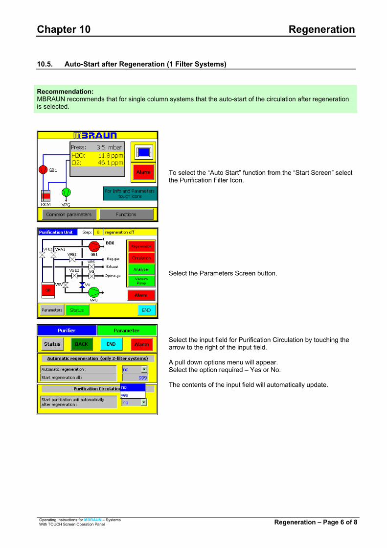
10.5. Auto-Start after Regeneration (1 Filter Systems)
Recommendation: MBRAUN recommends that for single column systems that the auto-start of the circulation after regeneration is selected.
To select the “Auto Start” function from the “Start Screen” select the Purification Filter Icon.
Select the Parameters Screen button.
Select the input field for Purification Circulation by touching the arrow to the right of the input field. A pull down options menu will appear. Select the option required – Yes or No. The contents of the input field will automatically update.
Operating Instructions for MBRAUN – Systems With TOUCH Screen Operation Panel Regeneration – Page 6 of 8

Chapter 10 Regeneration
10.6. Automatic Regeneration Mode
Note: Only available for systems equipped with two purifiers.
Select the Purification Filter icon on the start screen.
Select the Parameters button to go to the Purifier Parameter Screen
Select the input field for Automatic Regeneration by touching the arrow to the right of the input field. A pull down options menu will appear. Select the option required – Yes or No. The contents of the input field will automatically update.
To set the intervals between each automatic regeneration cycle select the “Start regeneration” field. The alpha-numeric pad opposite will appear.
Enter the desired value and select the enter button to input the data.
Operating Instructions for MBRAUN – Systems With TOUCH Screen Operation Panel Regeneration – Page 7 of 8

Chapter 10 Regeneration
Operating Instructions for MBRAUN – Systems With TOUCH Screen Operation Panel Regeneration – Page 8 of 8
10.7. Status of Regeneration
The current status of the regeneration of the purifier filter can be seen in two ways 10.7.1. Step Status
Selecting the Icon will open the screen left. At the top of the screen is an information bar for the regeneration status of the filters. In the diagram, on the right-hand side, you can see that the regeneration process is in its third step. Also indicated are the components that are activate for each stage of regeneration (VRA/VRS/EH) both in the information bar and as icon on the screen.
10.7.2. Time Status
Selecting the Status button in the Purifier Parameters Screen will open the screen shown left. This screen displays the total times for the Purification Filters (in systems with only one filter then only one set of detail are displayed.) The Automatic Active button is Password protected – for use by MBRAUN service personnel.

Chapter 11 Solvent Trap (LMF) Operation
Contents 11.1. General Information ................................................................................................................................2
11.1.1. Technical data: ...............................................................................................................................2
11.2. Manually Operated Solvent Trap ...........................................................................................................3 11.2.1. Changing the Filter Medium ...........................................................................................................4
11.3. PLC Controlled Solvent trap ..................................................................................................................5 11.3.1. Status of Solvent Trap (LMF) Filters ..............................................................................................5 11.3.2. Activating and Deactivating the Solvent Trap Mode ......................................................................5 11.3.3. Regeneration of the Solvent Trap ..................................................................................................6
11.4. Solvent Vapour Analyzer........................................................................................................................7
Table of Figures Figure 1: Principle of Circulation ..............................................................................................................2 Figure 2: Operation of Solvent Trap.........................................................................................................3 Figure 3: Status of Purifiers......................................................................................................................5
Operating Instructions for MBRAUN – System with TOUCH Screen Operation Panel Solvent Trap (LMF) Operation - Page 1 of 7

Chapter 11 Solvent Trap (LMF) Operation
11.1. General Information
Figure 1: Principle of Circulation
The Solvent Trap is available as an option.
GloveBox
Gas frombox
Gaspurification
It is designed to remove solvent vapours from the Glove Box Atmosphere.
Ultrapure gas
The Solvent Trap works in the same manner and in series with the H2O/O2 gas purification system (see also chapters Circulation and Regeneration.) The working gas permanently circulates between the glove box, the H2O/O2 gas purification system and the solvent removal system. This process guarantees absolutely stable values of gas purity and cost-efficient processing.
Caution: The solvent trap filter can only remove the solvent vapour when both the solvent trap (LMF) and the H2O/O2 gas purification (RKM) are both in circulation mode. There are two main types of Solvent removal systems: Manually operated solvent trap. PLC controlled Solvent Trap. In systems with 2 solvent trap removal columns circulation mode can run via one column while the other column is undergoing regeneration. The retention capability and capacity of the solvent trap depends on the type of solvent vapour to be removed from the box atmosphere. The retention characteristics also depend upon the type of catalyst used to within the solvent trap. Single column solvent traps and two column solvent traps without the regeneration option are filled with activated carbon. Regenerable solvent traps are filled will a certain type of molecular sieve. MBRAUN solvent traps are optimised for the removal of certain aromatic organic solvents, as well as, a variety of aliphatic organic solvents. 11.1.1. Technical data: Amount of filling: 5 kg of activated carbon (article no. 2182000) Suitably: for aromatic and aliphatic as well as halogenated organic solvents; petrol, kerosene,
butyric acid; in other cases the suitability must be confirmed by MBRAUN. Absorption capacity: ca. 100 g solvent per kg of activated carbon. However, the exact quantity depends on
the type of the solvent and the ambient conditions - in particular the ambient temperature.
Operating Instructions for MBRAUN – System with TOUCH Screen Operation Panel Solvent Trap (LMF) Operation - Page 2 of 7

Chapter 11 Solvent Trap (LMF) Operation
11.2. Manually Operated Solvent Trap
The diagram below shows the valve positions for operation of the Solvent Trap Unit.
Glove Box
Gas Purification
System
IN
Manometer LMF
Solvent Trap
Vacuum Pump OUT
Figure 2: Operation of Solvent Trap
MB LMF-II: OPERATION MODE MB LMF-II: BYPASS MODE
Operation: Gas purification system (GPS) and solvent absorber (LMF)
Operation: Gas purification system (GPS) without solvent absorber (LMF)
Open valve Open valve Open valve Close valve Close valve Close valve
Valve position "CLOSED" Valve position "CLOSED"
Operating Instructions for MBRAUN – System with TOUCH Screen Operation Panel Solvent Trap (LMF) Operation - Page 3 of 7

Chapter 11 Solvent Trap (LMF) Operation 11.2.1. Changing the Filter Medium
Note: MBRAUN recommends that the Solvent trap medium is changed at least annually. However, in cases of high solvent uses this may need to be more frequent. 1 kg of charcoal can adsorb approximately 100 g organic solvents . However, the exact quantity depends on the type of the solvent and the ambient conditions - in particular the ambient temperature. MBRAUN offers an optional solvent sensor. This sensor monitors the solvent concentration in the gas flow leaving the solvent filter, there by giving an promt warning of saturation of the filter. Warning: Using a system with a saturated solvent filter can lead to a damage of O-rings, the copper pipework and other components of the gas purification as well as of the glove box system. It may result in actual loss of the gas impermeability for the overall glovebox system. Caution: Wear protective mask, glasses and gloves whilst changing the activated carbon. Safe operation of the system is only possible with activated carbon, obtainable from MBRAUN. (article no. 2182000)
1. Switch the gas purification system into the bypass mode by setting the valves in the following positions:
Open valve
Close valve
Close valve
Valve - position "CLOSED"
2. Open outlet flange (OUT) at the solvent absorber (LMF) and empty the exhausted carbon in a tub. Please dispose the exhausted activated carbon correctly – observing all applicable environmental, safety and heath guidelines.
3. After the emptying the trap close the outlet flange (OUT) and open the inlet flange (IN) at the solvent ab-sorber (LMF).
4. Fill in new activated carbon; filling amount 5 kg. Afterwards close the inlet flange (IN) again.
5. Set hand valve on "EVACUATE" position. The minimum duration of the evacuation is 6 hours.
6. After the evacuation set the hand valve on "REFILL" position. Wait until the pressure indication at the manometer (MM) has reached the value "0".
7. After the refilling set the hand valve on "CLOSED" position. The solvent absorber (LMF) is again ready for operation.
Operating Instructions for MBRAUN – System with TOUCH Screen Operation Panel Solvent Trap (LMF) Operation - Page 4 of 7

Chapter 11 Solvent Trap (LMF) Operation
11.3. PLC Controlled Solvent trap
11.3.1. Status of Solvent Trap (LMF) Filters The Status of the Filters can be seen at all times on the start screen. The Icon for the filter differs for each mode. As show in figure 3. Figure 3: Status of Purifiers
Filter inactive Filter in Circulation (Active) Filter in Regeration
Note: The principle for circulation is the same for both 1 and 2 filter systems. The two filter system allows greater flexibly in operation of the box by allowing one filter to be regenerated whilst the other is in circulation (purifying) Mode. The position of buttons is shown for the Touch Panel (TP170B). However the principle for operation is the same for the TOUCH Panel series. Only those buttons relevant to the system supplied are displayed. 11.3.2. Activating and Deactivating the Solvent Trap Mode
Select the Functions button on the Start screen.
Select the Circulation Purifier button (red) to start the circulation over one of the purifier filters (RKM) (see circulation Mode for further information.)
Operating Instructions for MBRAUN – System with TOUCH Screen Operation Panel Solvent Trap (LMF) Operation - Page 5 of 7

Chapter 11 Solvent Trap (LMF) Operation
Select the Next button until the Function screen for the Solvent Trap (LMF) appears.
To acknowledge that the purifier is in Circulation Mode the button will change to green. Note: The Vacuum Pump activates automatically, if not previously activated.
The regeneration function for the selected filter will become blocked (button will display grey) until Circulation of the filter is cancelled. Note: If the system has a second filter option this will have its circulation function blocked. Regeneration of second filter is still available.
Selecting the Circulation Filter button a further time will switch off the circulation over the first purifier column.
Note: The Vacuum Pump remains activated until it is deactivated by selecting its function button.
11.3.3. Regeneration of the Solvent Trap The principle for regeneration of the solvent trap is the same as for the H2O/O2 gas purification system (see also chapter Regeneration.)
Note: Systems that are equipped with one solvent trap are fitted with a by-pass valve to allow the filter to be regenerated whilst the system operates over the H2O/O2 gas purification system.
Operating Instructions for MBRAUN – System with TOUCH Screen Operation Panel Solvent Trap (LMF) Operation - Page 6 of 7

Chapter 11 Solvent Trap (LMF) Operation
Operating Instructions for MBRAUN – System with TOUCH Screen Operation Panel Solvent Trap (LMF) Operation - Page 7 of 7
11.4. Solvent Vapour Analyzer
The solvent vapour analyser is available as an option. Access to the solvent trap analyzer screen is made by selecting the “Icon” button for the LMF on the “Start Screen and then further selecting the “Parameters” button.
The solvent vapour analyzer reading is proportional to the concentration of the solvent vapour after passage over the solvent trap. The sensitivity of the solvent vapour analyser depends upon the type of solvent being handled. Therefore the reading returned to the control panel is in the form of a voltage measurement (between 0V and 10V). The MBRAUN solvent vapour analyser can be calibrated for a specific solvent upon request.
Note: The Alarm setpoint Analyzer setting will differ for various solvents.

Blank Page
Operating Instructions for MBRAUN – Systems with TOUCH Screen Operation Panel Blank Page

Chapter 12 Parameters and Display Patterns
Contents 12. Glove Box Parameter Settings........................................................................................................ 2
General Information............................................................................................................................ 2 Status Overview ................................................................................................................................. 2
12.A. Setting the Box Pressure ................................................................................................................ 4
12.A.1. Freezer / Box Cooling Parameters.................................................................................................. 5
12.B. Gas Purification System (RKM) ...................................................................................................... 6 12.B.1. Parameters for Gas Purification System............................................................................. 6
12.B.1.1. Status of Gas Purification System............................................................................ 6 12.B.2. Functions for Gas Purification System................................................................................ 7
12.C. Solvent Vapour Filter Purification System (LMF) ......................................................................... 8 12.C.1. Parameters for Solvent Vapour Filter ................................................................................. 8
12.C.1.1. Status of Solvent Vapour Filter................................................................................. 8 12.C.2. Functions for Solvent Vapour Filter .................................................................................... 9
12.D. Common Parameters ..................................................................................................................... 10 Layout of Parameter Screens .......................................................................................................... 10
12.D.1. Alarm Setpoints................................................................................................................. 11 12.D.2. H2O / O2 Min/Max Values ................................................................................................ 11 12.D.3. Purifier Operating Hours ................................................................................................... 12 12.D.4. Purifier Trends .................................................................................................................. 12 12.D.5. System Settings ................................................................................................................ 13
12.D.5.1. Date and Time ........................................................................................................ 13 12.D.5.2. Touch Calibration ................................................................................................... 13 12.D.5.3. Screen Cleaning ..................................................................................................... 14 12.D.5.4. Language................................................................................................................ 14 12.D.5.5. WIN CE................................................................................................................... 14 12.D.5.6. Info.......................................................................................................................... 14 12.D.5.7. LOGIN / LOGOUT .................................................................................................. 14
12.D.6. Service Functions ............................................................................................................. 15 12.D.7. Box Purging Parameters................................................................................................... 15 12.D.8. Freezer / Box Cooling Parameters ................................................................................... 15
12.E. Functions ........................................................................................................................................ 16
12.F. Warnings and Error Messages ..................................................................................................... 17
12.G. Antechamber Functions ................................................................................................................ 18
Operating Instructions for MBRAUN – System with TOUCH Screen Operating Panel Parameters and Display Patterns – Page 1 of 18

Chapter 12 Parameters and Display Patterns
12. Glove Box Parameter Settings
General Information On the TP170B Operation Panel (TOUCH Screen) display all messages, values and parameters of the system can be displayed. The manufacturer for optimum operation of the system has set the parameters. If required, the user may change them. Status Overview When the system is activated the TP170B Touch Screen will display the “Start Screen”. This screen displays an overview of the system and reports reading for various sensors. (See diagram below). Figure 1: Start Screen
In the upper display area of the message level current operating values are permanently displayed, such as the box pressure.
Operating Instructions for MBRAUN – System with TOUCH Screen Operating Panel Parameters and Display Patterns – Page 2 of 18

Chapter 12 Parameters and Display Patterns The diagram below shows how each screen may be accessed. Each screen is numbered and are described further in the following sections:
Operating Instructions for MBRAUN – System with TOUCH Screen Operating Panel Parameters and Display Patterns – Page 3 of 18

Chapter 12 Parameters and Display Patterns
12.A. Setting the Box Pressure
When this display selected, the box pressure control is deactivated. You can enter the upper and lower working limit directly via the arrow-buttons “>” and “<” or by selecting the numeric box and then entering the value with the alpha/numeric keypad. The upper working limit cannot be set higher than the upper limit, and likewise the lower working limit cannot be set lower than the lower limit. How the box pressure control works is visible in the chart shown below. If the working limit is exceeded or the pressure falls below the lower limit, evacuation takes place for a short time or gas is refilled, until the pressure falls within the working limit of the value of the adjusted hysteresis. The hysteresis for the upper and the lower limit can be set independently from each other.
Operating Instructions for MBRAUN – System with TOUCH Screen Operating Panel Parameters and Display Patterns – Page 4 of 18

Chapter 12 Parameters and Display Patterns
12.A.1. Freezer / Box Cooling Parameters
The Freezer and Box Cooling functions are offered as an option. The use and setting for the Freezer and Box Cooling are described in their individual chapters.
Operating Instructions for MBRAUN – System with TOUCH Screen Operating Panel Parameters and Display Patterns – Page 5 of 18

Chapter 12 Parameters and Display Patterns
12.B. Gas Purification System (RKM)
Note: See also “Circulation” and “Regeneration” Chapters.
The screens below show how the gas purification system screens may be navigated and a brief description of the data that is displayed on each screen. For further information on the principles of the gas purification system see also the Circulation and Regeneration chapters.
The screen left shows the function status of the gas purification system (RKM). The top line gives the “regeneration step” and valve status for the regeneration process for each RKM filter. The main screen displays the gas purification system as a schematic diagram. At the bottom of the screen are button for navigating to further screens.
12.B.1. Parameters for Gas Purification System
The screen displays the parameters for the gas purifier (RKM) automatic regeneration. The options and parameters are entered by selecting the input filds to the right of the screen.
12.B.1.1. Status of Gas Purification System
This screen displays the time status for the gas purifiers (RKM). The numeric values are system generated. The total time purifier is the time, since insulation, that the purifier has been in active service. This figure would only be reset in the event of M.Braun service technicians replacing the filter medium.
Operating Instructions for MBRAUN – System with TOUCH Screen Operating Panel Parameters and Display Patterns – Page 6 of 18

Chapter 12 Parameters and Display Patterns 12.B.2. Functions for Gas Purification System
Function buttons for the gas purification system and glove box. Note: Systems fitted with dual filter solvent filters (LMF Auto) require circulation over one of the solvent filters (LMF) whenever the gas purification (LMF) circulation is used.
Operating Instructions for MBRAUN – System with TOUCH Screen Operating Panel Parameters and Display Patterns – Page 7 of 18

Chapter 12 Parameters and Display Patterns
12.C. Solvent Vapour Filter Purification System (LMF)
Note: See also “Circulation” and “Regeneration” Chapters.
The screens below show how the solvent filter screens may be navigated and a brief description of the data that is displayed on each screen. For further information on the principles of the solvent filter see also the Circulation, Regeneration and Solvent Filter chapters.
The screen left shows the function status of the solvent filter (LMF). The top line gives the “regeneration step” and valve status for the regeneration process for each LMF filter. The main screen displays the solvent filter system as a schematic diagram. At the bottom of the screen are button for navigating to further screens.
12.C.1. Parameters for Solvent Vapour Filter
The screen displays the alarm parameters for the solvent filter (LMF). For further details see Solvent Filter chapter.
12.C.1.1. Status of Solvent Vapour Filter
This screen displays the time status for the solvent filters (LMF). The numeric values are system generated. The total time purifier is the time, since insulation, that the puri-fier has been in active service. This figure would only be reset in the event of M.Braun service technicians replacing the filter me-dium.
Operating Instructions for MBRAUN – System with TOUCH Screen Operating Panel Parameters and Display Patterns – Page 8 of 18

Chapter 12 Parameters and Display Patterns 12.C.2. Functions for Solvent Vapour Filter
Function buttons for the solvent filter system. Note: Systems fitted with dual filter solvent filters (LMF Auto) require circulation over one of the solvent filters (LMF) whenever the gas purification (LMF) circulation is used.
Operating Instructions for MBRAUN – System with TOUCH Screen Operating Panel Parameters and Display Patterns – Page 9 of 18

Chapter 12 Parameters and Display Patterns
12.D. Common Parameters
Layout of Parameter Screens Below is an overview of the screens that may be accessed from the Common Parameters screen. Each pur-pose and function of each numbered screen is explained in the following section.
D.1 D.2 D.3
D.4 D.5 D.6
D.7 D.8
Operating Instructions for MBRAUN – System with TOUCH Screen Operating Panel Parameters and Display Patterns – Page 10 of 18

Chapter 12 Parameters and Display Patterns 12.D.1. Alarm Setpoints
Gas Purification Alarm limits may be entered by selecting the numeric field and then by using the al-pha/numeric keypad. As soon as the limits are exceeded a message is issued. 12.D.2. H2O / O2 Min/Max Values
This display shows the highest and lowest measured gas readings for the box atmosphere. The RESET button will clear these values and save the current value set until the atmosphere has altered to a new high or low and then that reading will be stored.
Operating Instructions for MBRAUN – System with TOUCH Screen Operating Panel Parameters and Display Patterns – Page 11 of 18

Chapter 12 Parameters and Display Patterns 12.D.3. Purifier Operating Hours Information regarding the total operation time of the system components can be seen on the “Operating Hours” Screen. Note: See also section “Status of Purifier Filters” in “Circulation” Chapter. See also section “Status of Regeneration” in “Regeneration” Chapter.
Information displayed is the total amount of hours that the components have been in use. Note: The times can only be reset by MBRAUN Service personnel e.g. upon replacement of a spare part by MBRAUN Service Technicians.
12.D.4. Purifier Trends
The trends screen is in the form of a time graph. There are 5 buttons on all graph displays. With the back<<, for-ward>> you can move along the time axis. With the Zoom+ and Zoom- you can select a narrower or broader time frame. The |< button returns you to the current time. The Y-axis may be calibrated between 50 and 1000 ppm by se-lecting the input field shown on the axis. The smallest time frame for the X-axis is 1 minute.
Operating Instructions for MBRAUN – System with TOUCH Screen Operating Panel Parameters and Display Patterns – Page 12 of 18

Chapter 12 Parameters and Display Patterns 12.D.5. System Settings
To access the “System Settings” screen select the “Common Parameters” from the “Start Screen”, and then select “System”.
12.D.5.1. Date and Time
The Date and time may be set to local setting by the customer. To change the time, follow directing in section “Input Fields and Buttons” in Chap-ter “Operation Panel TOUCHpanel (TP170b).”
12.D.5.2. Touch Calibration
Purpose: Depending on the fitting position as well as the viewing angle the touch screen may need to be calibrated to avoid any operating errors. You can calibrate the screen by selecting the Touch Calibration button.
Procedure: Start the calibrating procedure via the Touch Calibrating pushbutton. Five calibration crosses are displayed in succession at random points on the screen. Follow the instructions displayed on the screen and touch each calibration cross as it is displayed. Performing calibration With the calibration procedure completed, touch the screen at any point for accepting the latest calibration data. Rejecting calibration Wait for 30 seconds, until the overlaid timer-bar has reached zero, for rejecting the latest calibration data. In case calibration has been carried out incorrectly the latest values are not accepted.
Operating Instructions for MBRAUN – System with TOUCH Screen Operating Panel Parameters and Display Patterns – Page 13 of 18

Chapter 12 Parameters and Display Patterns 12.D.5.3. Screen Cleaning
After cleaning display has been started, all inputs via the touch screen are locked for 30 seconds. A run bar indicates the remaining time.
Protective foil For the Touch-Screen a protective foil is available. However this protective foil is not included in delivery of the TP170. The self-adhesive protective foil protects the screen against scratches and grime. In addition, the matt surface of the foil reduces any kind of reflec-tion. If required the protective foil can be removed at any time without leaving residual glue on the screen. If required a new foil would need to be applied. Caution For removing the protective foil do not use any sharp or pointed objects, such as knives, which may result in damage to Touch Screen. 12.D.5.4. Language
The Touch Operation Panel (TP170b) enables the user to select between preloaded lan-guages. MBRAUN systems are currently loaded with German and English. To change between lan-
guages stored on the TP170 simply press the “Language” button. 12.D.5.5. WIN CE
With the Win CE button activated, the Run-time program is completed and the panel is run down to the operating system level. If important filing procedures are running in the back-ground, this is the safest way of completing the filing procedures before the device is deacti-
vated. 12.D.5.6. Info
This area displays the following information: • Type of device, project
number, manufacturer’s address.
12.D.5.7. LOGIN / LOGOUT
These Buttons are for reserved for service use only.
Selecting the “LOGOUT” button will log the user out of the current “Password” level. That is the password level will be set to “zero”.
Operating Instructions for MBRAUN – System with TOUCH Screen Operating Panel Parameters and Display Patterns – Page 14 of 18

Chapter 12 Parameters and Display Patterns 12.D.6. Service Functions
The “Service” button
Note: The Service Function is password protected. It is reserved for MBRAUN service personnel only.
No Operating instructions are given for the service function. Information about the settings within the service mode is reserved for MBRAUN Service personnel only. 12.D.7. Box Purging Parameters
Two types of automatic purging options are available on the screen. The purging methods are selected by choosing either yes or no in the relevant input field on the right of the screen. Automaticaly purging with O2 limit value violation – will purge the glove box atmosphere as soon as the Oxygen limit value is over stepped e.g. if the oxygen limit value is 50 ppm and the sensor reading is 51 ppm then the Automatic purging will bring the oxygen content of the glove box atmosphere to below 50 ppm.
Automatically purging with box pressure alarm – will either refill or evacuate the glove box by 5 mbar if the box pressure alarm setpoint is overstepped. e.g. A system is required to be used with an under pressure and the pressure upper pressure alarm parameter is set at -1mbar. If the pressure increases above -1mbar then the box atmosphere will be evacuated by 5 mbar bringing the pressure down to -6mbar. Like wise if the under pressure setpoint is over stepped then the glove box will be filled by 5 mbar. 12.D.8. Freezer / Box Cooling Parameters
The Freezer and Box Cooling functions are offered as an option. The use and setting for the Freezer and Box Cooling are de-scribed in their individual chapters.
Operating Instructions for MBRAUN – System with TOUCH Screen Operating Panel Parameters and Display Patterns – Page 15 of 18

Chapter 12 Parameters and Display Patterns
12.E. Functions
Note: Via the Functions button in the Start Display, all existing functions can be selected and the status can be controlled. The individual displays comprise the functions in the form of buttons so that these functions are selectable within the individual function groups. Below are the normal function screens showing the location of all the common function buttons.
Operating Instructions for MBRAUN – System with TOUCH Screen Operating Panel Parameters and Display Patterns – Page 16 of 18

Chapter 12 Parameters and Display Patterns
12.F. Warnings and Error Messages
The “Alarm” Button appears in each screen. On occurrence of a fault or an error the “Alarm” button will flash. To view the error messages, push the “Alarm” button. This will open the Warnings Screen.
Figure 2: Warning Screen The messages that appear in the screen are in order of occurrence. The most recent message is the uppermost.
To acknowledge that a message has been read, select the message by touching the screen. The message will become highlighted on the screen. Select the Acknowledge button.
Messages that are no longer valid (e.g. The moister sensor reading is again within the alarm limit range) will be removed from the screen upon being acknowledged. Selecting the “Back” button will return to the previous screen.
Operating Instructions for MBRAUN – System with TOUCH Screen Operating Panel Parameters and Display Patterns – Page 17 of 18

Chapter 12 Parameters and Display Patterns
12.G. Antechamber Functions
The purpose and functions of the antechamber are described in the chapter – Antechamber Operation.
Operating Instructions for MBRAUN – System with TOUCH Screen Operating Panel Parameters and Display Patterns – Page 18 of 18

Chapter 13 Antechamber Operation (Standard)
Contents 13.1. General Information ................................................................................................................................2
13.2. Principle ...................................................................................................................................................2
13.3. Overview ..................................................................................................................................................3 13.3.1. Handmode (Standard) Antechamber Operation ............................................................................3 13.3.2. Automatic Antechamber Control ....................................................................................................3
13.4. Important Notes.......................................................................................................................................3
13.5. Transferring Material into the Box ........................................................................................................4 13.5.1. Preparation.....................................................................................................................................4 13.5.2. Evacuation in Manual Mode...........................................................................................................4 13.5.3. Refilling in Manual Mode................................................................................................................5
13.6. Information About the Automatic Antechamber Control....................................................................6
13.7. Antechamber Parameters.......................................................................................................................7 13.7.1. Parameter Definitions.....................................................................................................................7
13.8. Trends for Antechamber ........................................................................................................................8
13.9. Transferring Material Out of the Box ....................................................................................................9 13.9.1. Preparation.....................................................................................................................................9 13.9.2. Removal of Material from Antechamber.........................................................................................9
13.10. Circular Antechambers.........................................................................................................................10 13.10.1. Opening and Closing the Antechamber Door Outside the Box..................................................10 13.10.2. Opening and Closing the Antechamber Door Inside the Box.....................................................11
13.11. Mini Antechamber .................................................................................................................................12 13.11.1. Opening and Closing the Outer Door .........................................................................................12 13.11.2. Transferring Material Out of the Box ..........................................................................................14 Table of Figures Figure 1: Principle of Antechamber Operation ...........................................................................................2 Figure 2: Antechamber Control Screens ....................................................................................................3 Figure 3: Principle of Automation Antechamber Cycles .............................................................................6
Operating Instructions for MBRAUN –System with TOUCH Screen Operation Panel Antechamber Operation (Standard) – Page 1 of 14

Chapter 13 Antechamber Operation (Standard)
13.1. General Information
Antechambers are designed for transferring material into or out of the inert Glove Box System without polluting the box internal atmosphere during the respective procedures.
Antechamber Icon shown on Start Screen Antechamber Screen (Button for 2nd antechamber is also shown)
13.2. Principle
Figure 1: Principle of Antechamber Operation
Operating Instructions for MBRAUN –System with TOUCH Screen Operation Panel Antechamber Operation (Standard) – Page 2 of 14

Chapter 13 Antechamber Operation (Standard)
13.3. Overview
Figure 2: Antechamber Control Screens
Antechamber in Automatic Mode Antechamber in Handmode
13.3.1. Handmode (Standard) Antechamber Operation Handmode operation means that the functions of “Antechamber Evacuation” and “Antechamber Refilling” should be started and completed manually. 13.3.2. Automatic Antechamber Control The automatic antechamber control is a control software option. With this program available the evacuating/refilling cycles are automatically executed and controlled. Recommendation: MBRAUN recommends the use of Automatic Antechamber Operation, if available
13.4. Important Notes
The pressure within the antechamber may be given by: • A manometer mounted onto the antechamber, and/or • A pressure reading being displayed within the antechamber screen
(Yellow box above antechamber Icon) Caution: Never open box and outer antechamber doors simultaneously. An evacuated antechamber cannot be opened. Attempting to open an evacuated antechamber may damage the door locking mechanism. Never open a box door of an antechamber filled with ambient atmosphere. This would result in pollution of the box atmosphere and possibly in damage of measuring instruments and material within the box. Mechanical parts and seals should be checked regularly and protected against any contamination. When handling gases always keep to the national and international guidelines.
Recommendation: If the system is equipped with a separate pump, MBRAUN recommends that the pump is switched off (using the control panel) when not required. The pump will be restarted automatically on the next evacuation/refill cycle.
Operating Instructions for MBRAUN –System with TOUCH Screen Operation Panel Antechamber Operation (Standard) – Page 3 of 14

Chapter 13 Antechamber Operation (Standard)
13.5. Transferring Material into the Box
Note: Applies to systems without optional automatic antechamber control.
13.5.1. Preparation
• Observe Item “Important Notes” in this chapter.
• The antechamber door located inside the box is closed.
• The outer antechamber door is open.
• If a sliding tray is available: Pull out sliding tray; lay material on tray; then slide the tray together with the material into antechamber.
• If no sliding tray is available: Transfer the material directly into antechamber.
• Then close outer antechamber door.
Caution: If you transfer material with enclosed gaseous volume into the box the material should be able to withstand the pressure difference during the antechamber purge process (evacuation and refilling cycles). If possible open up any seals to enclosed gaseous volume – e.g. lids of bottles – so that the enclosed gases will also be exchanged during the pump/fill cycle.
13.5.2. Evacuation in Manual Mode
Press the Evacuate/Start Autom button to start evacuation.
The antechamber is being evacuated. Status indicator of the “Evacuate/Start Autom” button is green, an appropriate status message appears at the top of the Antechamber screen and the “Blue Bar” in the antechamber icon will decrease to show current status.
Recommendation: MBRAUN recommends an evacuation of the antechamber up to a value of <0.5 mbar.
Pressing the “Evacuate/Start Autom” button again will stop the process.
Operating Instructions for MBRAUN –System with TOUCH Screen Operation Panel Antechamber Operation (Standard) – Page 4 of 14

Chapter 13 Antechamber Operation (Standard)
13.5.3. Refilling in Manual Mode
Press the “Refill” button to start refilling the antechamber.
The antechamber is being refilled with gas from the box atmosphere. Status indicator of the “Refill” button is green, an appropriate status message appears at the top of the Antechamber screen and the “Blue Bar” in the antechamber icon will increase to show current status.
Note: Refill antechamber until pressure compensation between glove box and antechamber is attained.
Pressing the “Refill” button again will close the valve between the antechamber and the box.
Caution: For obtaining a high degree of purity, the antechamber should undergo repeated evacuation and refilling procedures. In this case for intermediate refilling a pressure of approximately 200 mbar is sufficient. The last refilling step always has to be back to box pressure.
Operating Instructions for MBRAUN –System with TOUCH Screen Operation Panel Antechamber Operation (Standard) – Page 5 of 14

Chapter 13 Antechamber Operation (Standard)
13.6. Information About the Automatic Antechamber Control
Note: Applies only to systems equipped with an optional automatic antechamber control.
Figure 3: Principle of Automation Antechamber Cycles
The diagram above shows how the intermediate refilling affects the atmosphere within the antechamber. The parameters of the automatic antechamber control have optimally been matched with the antechamber by the manufacturer. If required, they can be changed by the user. For information about changing the parameters refer to “Antechamber Parameters” Section.
Press the Evacuate/Start Autom button to start Automatic evacuation.
The antechamber is being evacuated.
The “Evacuate/Start Autom” button will release when the process has finished.
Operating Instructions for MBRAUN –System with TOUCH Screen Operation Panel Antechamber Operation (Standard) – Page 6 of 14

Chapter 13 Antechamber Operation (Standard)
13.7. Antechamber Parameters
Selecting the Parameters button from the “Antechamber” screen will open the parameters screen.
13.7.1. Parameter Definitions Intermediate refilling Level: .............................. Up to this value the oven is flooded with inert gas. Setpoint vacuum leaktest: ................................ At this pressure the vacuum leaktest will be started. Setpoint endvacuum: ........................................ Up to this pressure the antechamber will be evacuated. Pumping/refilling cycles: .................................. Number of evacuation and refilling cycles. Max. evacuating time [min]: ............................. If the set value “setpoint vacuum leaktest” is not reached in this
time the automatic antechamber cycle will be stopped and the warning: “pumping time exceeded” will be displayed
Max. leakrate [step value]: ................................ Parameter of the maximum pressure increase during the 2
steps of the vacuum leaktest within the measuring time frame. Example: 2x10⁻¹ mbar to 4x10⁻¹ mbar. If the parameter value is exceeded the antechamber process will be stopped and the warning: “antechamber leaking” will be displayed.
Operating Instructions for MBRAUN –System with TOUCH Screen Operation Panel Antechamber Operation (Standard) – Page 7 of 14

Chapter 13 Antechamber Operation (Standard)
13.8. Trends for Antechamber
All graphs are similarly designed. The measurements are displayed on a time-line graph. The trend graph for the antechamber is accessed by selecting the “Trends” button in the “Antechamber” screen.
The first trends screen displays the atmosphere pressure within the antechamber. The current atmosphere pressure is displayed at the top left-hand corner of the screen.
There are 5 buttons on all graph displays. With the (back) and (forward) buttons you can move along the time axis. With the and (zoom) buttons you can select a narrower or broader time frame. The
(re-set) button returns you to the current time. X - Axis = Timescale – details in hours and minutes Y - Axis = Measurement in mbar (pressure) or °C (temperature)
Operating Instructions for MBRAUN –System with TOUCH Screen Operation Panel Antechamber Operation (Standard) – Page 8 of 14

Chapter 13 Antechamber Operation (Standard)
13.9. Transferring Material Out of the Box
13.9.1. Preparation
• Observe Item “Important Notes” in this chapter.
• The outer antechamber door is closed.
• The antechamber door located inside the box is open.
• If a sliding tray is available: Pull out sliding tray; lay material on tray; then slide the tray together with the material into antechamber.
• If no sliding tray is available: Transfer the material directly into antechamber.
• Then close inner antechamber door.
13.9.2. Removal of Material from Antechamber
• Open the antechamber door located outside the box.
• If a sliding tray is available: Pull out sliding tray; remove material from tray; then slide the tray back into antechamber.
• If no sliding tray is available: Transfer the material directly out of the antechamber.
• Then close the outer antechamber door. Caution: Annoyance by bad smell is expected as soon as any waste purge gas is escaping to the surroundings. Environmental pollution and effects detrimental to health, however, are not known, but cannot be excluded. The manufacturer does not assume any liability. When using toxic or radioactive material manual, by no means the gas should escape to the environment. Information about pertinent alternative methods: [email protected]
Recommendation: Ensure that both outer and inner doors of the antechamber are closed when material is not being transferred through the antechamber. After having the outer antechamber door opened, it is recommended that at least one evacuation and refill cycle is completed for the antechamber to prevent possible condensation being deposited on the interior antechamber walls.
Operating Instructions for MBRAUN –System with TOUCH Screen Operation Panel Antechamber Operation (Standard) – Page 9 of 14

Chapter 13 Antechamber Operation (Standard)
13.10. Circular Antechambers
13.10.1. Opening and Closing the Antechamber Door Outside the Box
Observe all items of this chapter. Turn the locking mechanism until the antechamber door is free.
Caution: Antechamber under vacuum cannot be opened. If you try to open the antechamber under vacuum the opening mechanism can be damaged.
Carefully open the antechamber door in upward direction.
The antechamber door is held by the spring mechanism. It stays in the position (see picture).
Operating Instructions for MBRAUN –System with TOUCH Screen Operation Panel Antechamber Operation (Standard) – Page 10 of 14

Chapter 13 Antechamber Operation (Standard)
Carefully pull out sliding tray.
Closing the outer door is done in reverse order.
13.10.2. Opening and Closing the Antechamber Door Inside the Box
After execution of the evacuation/refill cycles: Opening and closing of the antechamber door inside the box is done in the same way as described for the outer door.
Caution: By no means open the inner door of an antechamber filled with air. This will result in polluting the inert box atmosphere and possibly in damaging measuring instruments and any material. Antechamber under vacuum cannot be opened. If you try to open the antechamber under vacuum the opening mechanism can be damaged.
Operating Instructions for MBRAUN –System with TOUCH Screen Operation Panel Antechamber Operation (Standard) – Page 11 of 14

Chapter 13 Antechamber Operation (Standard)
13.11. Mini Antechamber
13.11.1. Opening and Closing the Outer Door
Observe all items of this chapter. Turn the locking mechanism until the cover is free.
Caution Antechamber under vacuum cannot be opened. If you try to open the antechamber under vacuum the opening mechanism can be damaged.
Remove the cover.
Insert material into the antechamber.
Put the cover back on (please pay attention to the slide-ways) and turn the locking mechanism to close it.
Operating Instructions for MBRAUN –System with TOUCH Screen Operation Panel Antechamber Operation (Standard) – Page 12 of 14

Chapter 13 Antechamber Operation (Standard)
Execution of the evacuation/refill cycles: A. Turn the hand valve to the position “Evacuate”. The
antechamber will be evacuated.
B. Evacuate until the manometer shows a pressure of -0.9 up to -1.0 bar.
C. Turn the hand-valve to the position “refill”. Please pay attention to the description on the antechamber. The antechamber is purged with box gas. Purge until there is a pressure balance between the box and the antechamber. The reading on the manometer will change to zero.
Please process the described work cycle (Points A-C) at least twice, then the hand valve can be turned to the position “close”.
Caution: By no means open the inner door of an antechamber filled with air. This will result in polluting the inert box atmosphere and possibly in damaging measuring instruments and any material.
Operating Instructions for MBRAUN –System with TOUCH Screen Operation Panel Antechamber Operation (Standard) – Page 13 of 14

Chapter 13 Antechamber Operation (Standard)
Operating Instructions for MBRAUN –System with TOUCH Screen Operation Panel Antechamber Operation (Standard) – Page 14 of 14
Turn the locking mechanism until the cover is free.
Remove the cover and take the material out of the antechamber.
13.11.2. Transferring Material Out of the Box
Insert the material into the antechamber. Put the cover back on (please pay attention to the slide-ways) and turn the locking mechanism to close it.
Caution: Annoyance by bad smell is expected as soon as any waste purge gas is escaping to the surroundings. Environmental pollution and effects detrimental to health, however, are not known, but cannot be excluded. The manufacturer does not assume any liability. When using toxic or radioactive material manual, by no means the gas should escape to the environment. Information about pertinent alternative methods: [email protected]
Remove the outer cover and the material.

Chapter 14 Oven Antechamber
Contents 14.1. General Information ................................................................................................................................2
14.2. Operation of the Oven ............................................................................................................................2
14.3. Parameters for Oven Antechamber.......................................................................................................3 14.3.1. Parameter Definitions ................................................................................................................3
14.4. Trends for Oven Antechamber ..............................................................................................................4
Operating Instructions for MBRAUN – Systems with TOUCH Screen Operation Panel Oven Antechamber – Page 1 of 4

Chapter 14 Oven Antechamber
14.1. General Information
M.Braun glove boxes can be equipped with an oven. The oven can be installed at the place usually occupied by the antechamber, or as an additional antechamber on the opposite side, the rear ore on top of the glove box. The oven allows a process at an elevated temperature to be performed under vacuum and/or under an inert gas atmosphere. Typical applications are for the removal of water or solvents from either surfaces or substances prior to the material being transferred into the glove box. If the oven is placed at the side of the glove box then it typically functions as an antechamber, i.e. it allows the transfer of materials into and out of the inert Glove Box System without polluting the box internal atmosphere during the respective procedures. Note: See also Antechamber chapter.
The Oven antechamber has a slightly larger diameter and longer length that the standard antechamber to allow for the heating and cooling apparatus whilst maintaining similar internal dimension as a standard antechamber. M.Braun also offers a range of ovens for specific operations.
14.2. Operation of the Oven
See also “Antechamber Operation” Chapter.
The picture shows the schematic structure of the oven antechamber. The yellow status fields display the various actual values or process steps. In the section to the right of the screen are the oven functions. At the bottom of the screen are buttons for operation mode and status button. Selecting the appropriate button will open the “Oven Parameters“ screen or the “Trends“ Screen.
Note: Operation of the antechamber is possible with or without the heating cycle. Selecting the “Heating“ button switches the heating function.
Operating Instructions for MBRAUN – Systems with TOUCH Screen Operation Panel Oven Antechamber – Page 2 of 4

Chapter 14 Oven Antechamber
14.3. Parameters for Oven Antechamber
Selecting the Parameters button from the “Antechamber” screen will open the parameters screen. The parameters that are specific for the oven operation are accessed by pressing the “more” button.
14.3.1. Parameter Definitions Intermediate refilling Level: .............................. Up to this value the oven is flooded with inert gas. Setpoint vacuum leaktest: ................................ At this pressure the vacuum leaktest will be started. Setpoint endvacuum: ........................................ Up to this pressure the antechamber will be evacuated. Pumping/refilling cycles: .................................. Number of evacuation and refilling cycles. Max. evacuating time [min]: ............................. If the set value “setpoint vacuum leaktest” is not reached in this
time the automatic antechamber cycle will be stopped and the warning: “pumping time exceeded” will be displayed
Max. leakrate [step value]: ................................ Parameter of the maximum pressure increase during the 2
steps of the vacuum leaktest within the measuring time frame. Example: 2x10⁻¹ mbar to 4x10⁻¹ mbar. If the parameter value is exceeded the antechamber process will be stopped and the warning: “antechamber leaking” will be displayed.
Heating time: ...................................................... The maximum time that is allowed for the oven to reach the
desired temperature. Refill temperature: ............................................. The oven must cool to this level after the heating process,
following this it may be flooded with inert gas to the atmospheric pressure.
Note: Heating time and Refill temperature parameters when the system is equipped with the automatic cycle function
Operating Instructions for MBRAUN – Systems with TOUCH Screen Operation Panel Oven Antechamber – Page 3 of 4

Chapter 14 Oven Antechamber
14.4. Trends for Oven Antechamber
All graphs are similarly designed. The measurements are displayed on a time-line graph. The trend graphs for the oven antechamber are displayed over two screens and are accessed by selecting the “Trends” button in the “Antechamber” screen.
The first trends screen displays the atmosphere pressure within the antechamber. The current atmosphere pressure is displayed at the top left-hand corner of the screen.
The second “Trends” screen displays the temperature within the antechamber. On the left-hand side of the screen is an input field that allows the Y-axis scale to be altered between the range of 1°C and 800°C. The current atmosphere pressure and temperature are displayed at the top left-hand corner of the screen.
There are 5 buttons on all graph displays. With the (back) and (forward) buttons you can move along the time axis. With the and (zoom) buttons you can select a narrower or broader time frame. The
(re-set) button returns you to the current time. X - Axis = Timescale – details in hours and minutes Y - Axis = Measurement in mbar (pressure) or °C (temperature)
Operating Instructions for MBRAUN – Systems with TOUCH Screen Operation Panel Oven Antechamber – Page 4 of 4

Chapter 15 Analysers Contents 15.1. General Information .......................................................................................................................... 2
15.1.1. Connection Diagram................................................................................................................. 3 15.1.2. Activating the Analyser(s)......................................................................................................... 4 15.1.3. Deactivating the Analyser(s) .................................................................................................... 4
15.2. Calibration of Sensors...................................................................................................................... 5
15.3. Oxygen Analyser (MB OX-SE-1) ...................................................................................................... 5 15.3.1. General..................................................................................................................................... 5 15.3.2. Construction ............................................................................................................................. 5 15.3.3. Connector................................................................................................................................. 6 15.3.4. Technical Data ......................................................................................................................... 6 15.3.5. Installation ................................................................................................................................ 7 15.3.6. Trouble-shooting ...................................................................................................................... 7
15.4. Oxygen Analyser (MB OX-SE-3) ...................................................................................................... 8 15.4.1. General Information.................................................................................................................. 8 15.4.2. Description ............................................................................................................................... 8 15.4.3. Technical Data ......................................................................................................................... 8
15.5. Moisture Analyser (MB MO-SE-1).................................................................................................... 9 15.5.1. General..................................................................................................................................... 9 15.5.2. Technical Data ......................................................................................................................... 9 15.5.3. Connector............................................................................................................................... 10 15.5.4. Trouble Shooting .................................................................................................................... 10 15.5.5. Maintenance: Sensor Cleaning .............................................................................................. 10 Table of Figures Figure 1: Types of Sensor .................................................................................................................... 2 Figure 2: Connection Diagram.............................................................................................................. 3 Figure 3: Procedure for Cleaning Moisture Sensor ............................................................................ 11
Operating Instructions for MBRAUN – Systems with TOUCH Screen Operation Panel Analysers – Page 1 of 12

Chapter 15 Analysers 15.1. General Information
Note: Applies to systems with optional H2O and/or O2 analysers. Systems with analyser option are equipped with an “Analyser” function button. The measured H2O and/or O2 values are shown on the operation panel display. Not all analysers are necessarily included as selected options.
Figure 1: Types of Sensor
MB-OX-SE-1 MB-OX-SE-3
MB-MO-SE-1
Operating Instructions for MBRAUN – Systems with TOUCH Screen Operation Panel Analysers – Page 2 of 12

Chapter 15 Analysers 15.1.1. Connection Diagram Figure 2: Connection Diagram
Operating Instructions for MBRAUN – Systems with TOUCH Screen Operation Panel Analysers – Page 3 of 12

Chapter 15 Analysers
Operating Instructions for MBRAUN – Systems with TOUCH Screen Operation Panel Analysers – Page 4 of 12
15.1.2. Activating the Analyser(s) Note High levels of ambient atmosphere within the box could damage or pollute the measuring instruments, the box atmosphere and any materials within the box. Ensure that the antechamber atmosphere has been purged, as required, before opening the inner antechamber door. Do not open both doors of an antechamber at the same time causing the ambient atmosphere to enter the box.
Start display with the analysers switched off. To activate the analysers, open the Functions screen by selecting the “Function” button.
Selecting the “Analyser” button will activate the connected analysers.
The button will display the status change by changing from red (not active) to green (active).
The reading from the analysers can now be seen on the start screen. The readings are also repeated on various other screens. The analyser readings are in the following format: Press: xxx Pa H2O*: xxx ppm O2**: xxx ppm Box Cooling***: xxx °C
* Is displayed only when the system is provided with a moisture analyser. ** is displayed only when the system is provided with an oxygen analyser. *** is displayed only when the system is provided with cooling.
15.1.3. Deactivating the Analyser(s) Deactivating the Analysers is carried out by the same procedure as activation.
The Analyser button will display the status change by changing from green (active) to red (not active).

Chapter 15 Analysers 15.2. Calibration of Sensors
All MBRAUN sensors have a certified calibration before shipping.
Recommendation MBRAUN recommends that sensors are calibrated annually by MBRAUN technicians. Quotation on request from MBRAUN Service Department.
The calibration cycle depends on the demand for accuracy as well as on the conditions of the gas to be measured (purity, spurious gases etc.)
15.3. Oxygen Analyser (MB OX-SE-1)
15.3.1. General The MB-OX-SE-1 sensor has been designed to control the atmosphere of MBRAUN Systems for residual Oxygen content. The measuring range is 0 to 1000 ppm. The measuring range from 0 – 100 ppm is linear. The measurement range is calibrated for use below 1000 ppm as the sensor output, above 100 ppm, not truly linear.
This probe can be used in particular for the control of a purge process – e.g. during the initial initialisation of a MBRAUN glove box system. The probe can be operated with PLC-systems, which are integrated in MBRAUN Systems as standard equipment, or with MB SSD-DIS monitors, which are available separately.
The use of the probe for other applications can be possible from case to case, however this has to be approved by MBRAUN first.
The semiconductor sensor made of Zirconium dioxide is specific for oxygen, but because of the high sensor temperature and the catalytic activity of the platinum coating of the sensor there are low cross-sensitivities for hydrogen as well as possible reactions with aggressive gaseous substances, that can reduce the operational life of the sensor.
Caution Operating the sensor at oxygen levels of >1000 ppm (e.g. in air) does not irreversibly damage the sensor element, but it should be avoided. If exposed to air, it will take several hours until the sensor will measure low oxygen levels correctly in Inert Gas.
15.3.2. Construction The MB-OX-SE1 consists of the sensor and the special electronics separated by a gas-tight NW40 clamp flange. The sensor is protected against physical damage by a protective cage. The sensor leads are connected to the electronics by vacuum-tight feed-throughs. The electronics are contained in an airtight box mounted directly to the back of the NW40 flange. The measuring electronics is operated by 24 VDC. It supplies a 0 to 10 VDC output proportional to the oxygen concentration. An additional input switches the heating element of the sensor on and off to control the temperature of the sensor. If this input is not used, an internal jumper has to be set to operate the probe. Electronics and Sensor Element have been factory-calibrated with certified calibration gases; there are no user-accessible adjustment points. The electronics and the sensor are calibrated with NIST traceable gases.
Warning:
The probe may not be used in flammable or explosive gas atmospheres (measured gas or outside environment).
It lies within the responsibility of the user to ensure, that flammable or explosive gas mixtures cannot be exposed to the sensor head during operation.
(At the discretion of MBRAUN GmbH, a calibration procedure can be supplied, for trained technicians to recalibrate the sensor’s low range, 0-100ppm)
Operating Instructions for MBRAUN – Systems with TOUCH Screen Operation Panel Analysers – Page 5 of 12

Chapter 15 Analysers 15.3.3. Connector
Connector 8-pole socket (RJ45):
Pin-No. Contact 1 Supply Ground 2 Switching ON/OFF 24 V 3 Signal Ground 4 Livebit (O2) 5 Not Connected 6 Signal 0 - +10 V 7 Supply +24 V 8 Supply Ground
15.3.4. Technical Data Mechanical Length over all: ..............................................190 mm, height 80 mm, depth 58 mm Sensor-part: ...................................................length 45 mm, diameter 26 mm Flange: ...........................................................NW 40 KF Weight:...........................................................0.7 kg Electrical Supply voltage: ..............................................24 VDC ± 10% Protection class:.............................................IP 53 Environment Ambient temperature: ....................................+15 to +27 °C Pressure:........................................................800 to 1200 mbar (Differential pressure sensor
to electronics max. ≈100 mbar) Volumetric flow-rate: ......................................100 l/h (±10%) Measuring Range: ...........................................................0 - 1000 ppm oxygen Sensitivity:......................................................10 mV / ppm Response time (0 - 90 %): .............................approximately 10 sec (0 - 90 %) Warm-up time: ...............................................10 min (for < 10 ppm approx. 6 hr) Accuracy1): .....................................................2 % of displayed value ±1 ppm up to 100 ppm Drift at 10 ppm: ..............................................10 % / year Sensor life2): ...................................................ca. 5 years Cross sensitivities3) ........................................Gaseous, oxygen-containing compounds can lead to an
apparent oxygen signal.
1) In a clean inert gas atmosphere, without interfering, cross sensitive or reactive gases. 2) In absence of reactive gases (like halogenated hydrocarbons, halogens, other halogen containing gases or vapours, sulphur dioxide, hydrogen sulphide, silanes,
hydrogen). Contact MBRAUN Service for further advice. 3) In particular: oxygen containing hydrocarbons with a high vapour pressure (Ethanol, Diethyl ether) carbon monoxide, carbon dioxide, nitrogen dioxide, sulphur
dioxide. After extended operation in an oxygen free environment there will be a cross sensitivity towards water vapour. The cross sensitivities named lead mostly to a very week additional signal that can be tolerated. Contact MBRAUN Service for further advice.
Operating Instructions for MBRAUN – Systems with TOUCH Screen Operation Panel Analysers – Page 6 of 12

Chapter 15 Analysers 15.3.5. Installation Caution Before applying electrical power the sensor should be exposed to clean inert atmosphere for at least 1 minute.
The oxygen probe is mounted vacuum-tight on an appropriate NW40 flange by means of a centring ring and a clamp. The usual way is to use a NW40 t-piece in the gas flow piping. This will guarantee that the sensor is exposed to direct gas-flow and is not located in a dead space. The sensor only requires a low flow rate and is not flow sensitive up to flow rates of 2 m/s. The plug connection to the control unit must not be made before the whole box-system has been purged sufficiently with inert gas. The operation of the probe as well as the display of the measured values is performed by the control unit. 15.3.6. Trouble-shooting The oxygen probe does not contain user-serviceable parts. Therefore in case of defects the probe has to be sent complete and unopened to MBRAUN or the authorized representative. On request MBRAUN may offer exchange probes.
Description of malfunction What to do The display measuring value comes very slowly below 10 ppm, whereas it is certain that the real value is much lower (Check, whether this is really the case or the display is correct).
The sensor is still charged with oxygen by a previous operation at high oxygen concentrations or long storage in air. In this case operate the sensor for some hours in clean inert atmosphere and it will come down. The sensor has a very stable zero-point, so before sending the probe for repair you must exclude the possibility that e.g. hydrogen in ppm-levels is present or was present in higher levels.
Operating Instructions for MBRAUN – Systems with TOUCH Screen Operation Panel Analysers – Page 7 of 12

Chapter 15 Analysers 15.4. Oxygen Analyser (MB OX-SE-3)
15.4.1. General Information The oxygen probe MB OX-SE-3 serves to monitor the amount of oxygen in an inert gas atmosphere (nitrogen, argon or helium) of a MBRAUN glove box system. The probe has a wide range from 0 to 25 vol% of oxygen concentrations. Therefore this probe can be used in particular for the control of a purge process – e.g. during the initial initialisation of a MBRAUN glove box system. The probe can be operated with PLC-systems, which are integrated in MBRAUN Systems as standard equipment, or with MB SSD-DIS monitors, which are available separately.
The use of the probe for other applications can be possible from case to case, however this has to be approved by MBRAUN first.
15.4.2. Description The oxygen probe MB OX-SE-3 comprises a sensor along with the electronics. The sensor-head is protected from external mechanical effects by means of a sturdy screw cap.
The sensor-head is a miniaturized Zirconium dioxide plate operated at elevated temperature, which is controlled by a platinum resistor. The electronics are supplied with 24 V DC and deliver a 0 - 10 V signal in proportion to the concentration of oxygen. An additional input for the electronics allows the switching on and off the sensor heating by means of the PLC or as the case may be the MB SSD-DIS monitor.
The electronics and the sensor are calibrated with NIST traceable gases.
Warning:
The probe may not be used in flammable or explosive gas atmospheres (measured gas or outside environment).
It lies within the responsibility of the user to ensure, that flammable or explosive gas mixtures cannot be exposed to the sensor head during operation..
15.4.3. Technical Data
Mechanical Length over all: ..............................................190 mm, height 80 mm, depth 58 mm Sensor-part: ...................................................length 45 mm, diameter 26 mm Flange: ...........................................................NW 40 KF Weight:...........................................................0.7 kg
Electrical Supply voltage: ..............................................24 V DC ±10% Protection class:.............................................IP 53
Environment Ambient temperature: ....................................+15 to +27 °C Pressure:........................................................800 to 1200 mbar (Differential pressure sensor to
electronics max. ≈100 mbar) Volumetric flow-rate: ......................................100 l/h (±10%)
Measuring Range: ...........................................................0 - 25 vol% oxygen Sensitivity:......................................................400 mV / % Response time (0 - 90 %): .............................approximately 10 sec. (0 - 90 %) Warm-up time: ...............................................10 min (for < 10 ppm approx. 6 hr) Accuracy1): .....................................................< 1 % vol Drift at 20.9 %vol:...........................................0.5 % vol/24h Sensor life2): ...................................................ca. 5 years Cross sensitivities3) ........................................Gaseous, oxygen-containing compounds can lead to an
apparent oxygen signal. 1) In a clean inert gas atmosphere, without interfering, cross sensitive or reactive gases. 2) In absence of reactive gases (like halogenated hydrocarbons, halogens, other halogen containing gases or vapours, sulphur dioxide, hydrogen sulphide, silanes,
hydrogen). Contact MBRAUN Service for further advice. 3) In particular: oxygen containing hydrocarbons with a high vapour pressure (Ethanol, Diethyl ether) carbon monoxide, carbon dioxide, nitrogen dioxide, sulphur
dioxide. After extended operation in an oxygen free environment there will be a cross sensitivity towards water vapour. The cross sensitivities named lead mostly to a very week additional signal that can be tolerated. Contact MBRAUN Service for further advice.
Operating Instructions for MBRAUN – Systems with TOUCH Screen Operation Panel Analysers – Page 8 of 12

Chapter 15 Analysers 15.5. Moisture Analyser (MB MO-SE-1)
15.5.1. General The MB-MO-SE1 has been designed to control the atmosphere of the MBRAUN Systems for residual moisture content. The measuring range is 0 to 500 ppm. The measuring range from 0 – 50 ppm is linear. The measurement range is calibrated for use below 500 ppm as the sensor output, above 50 ppm, is not truly linear. The sensor element is a “double helix” made of platinum wire fixed on a special insulation material. The sensor is coated with phosphoric acid that is totally dehydrated. Water molecules in the gas penetrate the acid layer and the electrolysis of the resulting H+ and OH- ions to H2 and O2 produces an electric current. So, the water molecules coming to the sensor surface are removed and the resulting current is depending on the concentration of the water molecules in the gas. The primary signal is compensated for temperature and amplified. 15.5.2. Technical Data
Mechanical Length over all: ..............................................205 mm, height 80 mm, depth 58 mm Sensor-part: ...................................................length 42 mm, diameter 14 mm Flange: ...........................................................NW 40 KF Weight:...........................................................0.7 kg Electrical Supply voltage: ..............................................24 VDC ±10% Protection class:.............................................IP 53 Environment Ambient temperature: ....................................+15 to +27 °C Pressure:........................................................800 to 1200 mbar (Differential pressure sensor to
electronics max. ≈100 mbar) Volumetric flow-rate: ......................................100 l/h (±10%) Measuring Range: ...........................................................0 - 500 ppm moisture Sensitivity:......................................................20 mV / ppm Response time (0 - 90 %): .............................approximately 120 sec. (0 - 90 %) Warm-up time: ...............................................10 min (for < 10 ppm approx. 6 hr) Accuracy1):
High precision range (0 - 10 ppm): ...........better than 5 % of value Wide range (10 - 100 ppm):......................better than 20 % of value
Drift at 10 ppm: ..............................................10% / year Sensor life2): ...................................................ca. 5 years 1) without interfering gases like NH32) with regular maintenance
Operating Instructions for MBRAUN – Systems with TOUCH Screen Operation Panel Analysers – Page 9 of 12

Chapter 15 Analysers 15.5.3. Connector
8-pole socket (RJ45):
Pin-No. Connection 1 Supply Ground 2 Switching ON/OFF 24 V 3 Signal Ground 4 Not Connected 5 Live bit (H2O) 6 Signal 0 - +10 V 7 Supply +24 V 8 Supply Ground
15.5.4. Trouble Shooting The oxygen probe does not contain user-serviceable parts. Therefore, in case of defects the probe has to be sent complete and unopened to MBRAUN GmbH or the authorized representative. On request, MBRAUN may offer exchange probes. 15.5.5. Maintenance: Sensor Cleaning Recommendation: MBRAUN recommends a maintenance cleaning procedure every 3 months.
Caution: When cleaning the sensors it is important that contamination from the ambient atmosphere is prevented. Therefore MBRAUN recommends that the box parameters are set to a pressure of between +1.0 and +5.0 mbar (see parameters chapter) and that the circulation mode is switched OFF.
Note: To achieve optimal moisture measurements the sensor is recommended to be closely inspected within a period of three months.
This routine maintenance consists in cleaning the platinum winding of the MB MO-SE-1 and moistening it with phosphoric acid H3PO4. The following aids are required for disassembling and maintaining the MB MO-SE-1. Tool for disassembly (screwdriver) Soft, absorbent, lint free cloth (cotton) Small quantity of phosphoric acid (H3PO4). Protective clothing, including gloves and goggles One dummy plug for the open circulation piping (DN40) Caution: Be cautious when handling phosphoric acid. Wear protective gloves and goggles. Any phosphoric acid getting in contact with your skin should immediately be rinsed off using running water. When getting in contact with your eyes, the acid should immediately be rinsed also using running water; afterwards you should immediately consult a doctor. Caution: Prior to any maintenance work the moisture measurement should be deactivated, i.e. the analyser is switched off; refer to subchapter “Deactivating the analyser(s)”.
Operating Instructions for MBRAUN – Systems with TOUCH Screen Operation Panel Analysers – Page 10 of 12

Chapter 15 Analysers Figure 3: Procedure for Cleaning Moisture Sensor
Disconnect plug connector.
Loosen clamp.
Insert dummy plug.
Tighten flange clamp.
Unscrew protective cover.
Moisten sensor with distilled water.
1 2
3 4
5 6
Operating Instructions for MBRAUN – Systems with TOUCH Screen Operation Panel Analysers – Page 11 of 12

Chapter 15 Analysers
Carefully clean and dry winding.
Moisten winding with phosphoric acid.
Remount protective cover.
Remove clamp and dummy plug.
87
9 10
12
11Insert measuring probe and re-clamp.
Tighten clamp.
Insert plug connector.
13
Operating Instructions for MBRAUN – Systems with TOUCH Screen Operation Panel Analysers – Page 12 of 12

Chapter 16 Compressor Cooling
Contents 16.1. General Information ............................................................................................................................. 2
16.2. Operation of the Box Cooling Unit ..................................................................................................... 2
16.3. Setting the Box Cooling Parameters.................................................................................................. 3
Operating Instructions for MBRAUN – Systems with TOUCH Screen Operation Panel Compressor Cooling – Page 1 of 3

Chapter 16 Compressor Cooling
16.1. General Information
The purpose of the cooling unit is to cool the Glove Box atmosphere after being exposed to excess heat. This heat source may be from an oven/furnace, welding or from plasma burning within the system etc. The cooling unit directs a cooling airflow to a specific area, therefore allowing the maximum cooling effect on items that are placed in the current. The normal Glove Box circulation will cause an overall cooling effect within the system. Caution: When the cooling unit is not in operation, there is a reduced airflow with the unit. Therefore, during manual purging, extra care is required for the area around the cooling unit to ensure that the area is completely purged.
The range of the Box Cooling Temperature is +10°C to +40°C
16.2. Operation of the Box Cooling Unit
The cooling unit is controlled by the Touch Panel.
To activate the Box Cooling function select the Functions Button on the Start Screen.
Select the “Box Cooling” button. The button will turn to green when the Box Cooling is active. To deactivate the “Box Cooling” select the button again – the button will return to the colour red.
Operating Instructions for MBRAUN – Systems with TOUCH Screen Operation Panel Compressor Cooling – Page 2 of 3

Chapter 16 Compressor Cooling
Operating Instructions for MBRAUN – Systems with TOUCH Screen Operation Panel Compressor Cooling – Page 3 of 3
16.3. Setting the Box Cooling Parameters
Select the “Common Parameters” button on the start screen. Note: If the Glove-Box is equipped with a Box Cooling unit the current temperature will be displayed on the “Start Screen”.
Select the “Freezer/Box Cooling” Button from the common Parameters screen to access the Parameter Screen for the Box Cooling Unit.
The Temperature may be set by selecting the input field “Setpoint temp. box cooling:” Enter the desired temperature and press the enter button. The range for the box cooling is from +10°C to +40°C. If the unit is active, the cooling unit will start cooling when the setpoint temperature is over-stepped.

Blank Page
Operating Instructions for MBRAUN – Systems with TOUCH Screen Operation Panel Blank Page

Chapter 17 Freezer
Contents 17.1. General Information .......................................................................................................................... 2
17.2. Purging the Freezer .......................................................................................................................... 2
17.3. Operation of the Freezer................................................................................................................... 3
17.4. Setting the Freezer Parameters ....................................................................................................... 4
Table of Figures Figure 1: Freezer - Door Closed..................................................................................................... 2 Figure 2: Freezer – Door Open ....................................................................................................... 2
Operating Instructions for MBRAUN – Systems with TOUCH Screen Operation Panel Freezer – Page 1 of 4

Chapter 17 Freezer
17.1. General Information
Inner dimensions
Height................................... 423.0 mm Width.................................... 266.0 mm Depth ................................... 162.5 mm Inner volume ...................... ±18.3 litres Cooling Function Cooling Range ..................... +10°C to -35°C ............................................ (-30°C if ambient temp > 30°C) Ambient Temp. Range......... 0°C to +32°C
Figure 1: Freezer - Door Closed
17.2. Purging the Freezer
Caution: It is important that the interior of the freezer is fully purged of ambient atmosphere before the Glove Box is used. Failure to purge this area could cause the box atmosphere to become polluted upon opening of the freezer door, thus causing damage to the box equipment, and/or material within the Glove Box.
Before the Glove Box is used the System must be purged (see Chapter – Purging the System). During the Glove Box purging process it is important that all areas are fully purged of ambient atmosphere. With the freezer in the Glove Box it is important that not only the area around the freezer unit is purged but also the area within the Freezer.
Figure 2: Freezer – Door Open
Operating Instructions for MBRAUN – Systems with TOUCH Screen Operation Panel Freezer – Page 2 of 4

Chapter 17 Freezer
17.3. Operation of the Freezer
To Activate the Freezer function select the Functions Button on the Start Screen.
Select the “Freezer” button. The button will turn to green when the Freezer is active. To deactivate the “Freezer” select the button again – the button will return to the colour red.
The inner temperature of the freezer is controlled by the Touch Panel. (See Setting of Freezer Parameters below) The door for the freezer is opened, closed and secured by a lever attached o the door. For additional security the door may be locked with a key. Within the Freezer compartment there are shelf supports to give a range of settings for additional shelving.
Operating Instructions for MBRAUN – Systems with TOUCH Screen Operation Panel Freezer – Page 3 of 4

Chapter 17 Freezer
Operating Instructions for MBRAUN – Systems with TOUCH Screen Operation Panel Freezer – Page 4 of 4
17.4. Setting the Freezer Parameters
Select the “Common Parameters” button on the start screen. Note: If the Glove-Box is fitted with a freezer unit the current temperature will be displayed on the “Start Screen”.
Select the “Freezer/Box Cooling” Button from the common Parameters screen to access the Parameter Screen for the Freezer Unit.
The Temperature may be set by selecting the input field “Setpoint Temperature Freezer:” Enter the desired temperature and press the enter button. Range for freezer temperature is from -40°C to +20°C. Note: The “actual value freezer” field returns the current temperature within the freezer – the value is generated by the system.

Chapter 18 Dust Filters
Contents 18.1. General Information ............................................................................................................................. 2
18.2. Technical Data...................................................................................................................................... 2
18.3. Exchanging Dust Filters ...................................................................................................................... 3 18.3.1. Method for Exchanging the Filter: ............................................................................................... 3
Table of Figures Figure 1: Removing Filter...................................................................................................................... 3 Figure 2: Replacing Filter ...................................................................................................................... 3
Operating Instructions for MBRAUN – Systems with TOUCH Screen Operation Panel Dust Filters – Page 1 of 3

Chapter 18 Dust Filters
18.1. General Information
MBRAUN glove boxes are equipped with dust filters at the gas outlet, as well as, at the gas inlet piping. The former protects the gas purification system against dust particles the maybe generated by the user inside the glove box. The latter filter ensure optimal particle free incoming gas.
18.2. Technical Data
The filter that is commonly used within the M.Braun Glove Box system has the following characteristics:-
The standard filter is of a HEPA format (class H14)- i.e. filtering 99.995% of particles – typically down to 0.2 microns. Note: M.Braun can also supply finer filters (e.g. Class U15 – Filtering 99.9995% of particles) upon request.
Operating Instructions for MBRAUN – Systems with TOUCH Screen Operation Panel Dust Filters – Page 2 of 3

Chapter 18 Dust Filters
Operating Instructions for MBRAUN – Systems with TOUCH Screen Operation Panel Dust Filters – Page 3 of 3
18.3. Exchanging Dust Filters
Depending on the usage of the glove box system the filters need to be exchanged at least once a year. 18.3.1. Method for Exchanging the Filter: Figure 1: Removing Filter
Unscrew used dust filter.
Figure 2: Replacing Filter
Screw new dust filter in place.
Note: Depending upon the substances used inside the glove box, the replaced filter may need to be treated with care outside of the glove box atmosphere. Please refer to all local Environmental, Safety and Health guidelines that may apply for the type of substances used within the glove box.

Blank Page
Operating Instructions for MBRAUN – Systems with TOUCH Screen Operation Panel Blank Page

Chapter 19 Gloves
Contents 19.1. General Information ............................................................................................................................. 2
19.2. Technical Data...................................................................................................................................... 2
19.3. Replacing Gloves ................................................................................................................................. 3
19.4. Glove Port Covers................................................................................................................................ 4
19.5. Standard Spare Parts and Accessories for M.Braun Gloves .......................................................... 5
Operating Instructions for MBRAUN Systems with TOUCH Screen Operation Panel Gloves – Page 1 of 5

Chapter 19 Gloves
19.1. General Information
M.Braun exclusively uses gloves made of butyl. A feature of this flexible material is the good comfortable grip even at low temperatures (Temperature range from -40 °C to +90 °C). The following graphic chart shows, that butyl compared to hypalon and neoprene evidently has the most favourable values regarding the permeability for different gases and for water vapour.
Note: For working with higher temperatures M.Braun also offers gloves made of butyl with a hypalon layer.
0,00
2,00
4,00
6,00
8,00
10,00
12,00
14,00
16,00
18,00
20,00
(P)
N2 CO2 Air O2 He Moisture(/100)
Gas Permeabily Constant Comparison Chart
BUTYL HYPALON NEOPRENE
Note: Permeability Constant (P) = gas flow through a material of 1cm thickness at a standard pressure and temperature. It is measured at a rate of 10-9cm3 gas/s.
19.2. Technical Data
Product: ..........MB Gloves. Type:................Special gloves made of brom-butyl for Glove Box Systems. Design: ............Various diameters, sizes and shapes.
Operating Instructions for MBRAUN Systems with TOUCH Screen Operation Panel Gloves – Page 2 of 5

Chapter 19 Gloves
19.3. Replacing Gloves
Recommendation: M.Braun recommends that the gloves are replaced at regular intervals. The gloves must be changed upon signs of wear and tear that may or have caused a leak.
Caution: Before changing gloves ensure that the glove box is atmosphere is safe to breathe. If necessary purge and fill the glove box with ambient air before attempting to change gloves.
The Gloves are secured by two O-rings.
To remove the gloves remove the O-rings and removes the glove as shown
To replace the glove -
place the glove over the port so that the rim of the glove locates in the port’s innermost groove (the outer 2 grooves are for locating the O-rings that secure the glove).
Caution: Ensure that the correct type of glove is chosen e.g. left or right hand, or ambidextrous and of the correct size
Operating Instructions for MBRAUN Systems with TOUCH Screen Operation Panel Gloves – Page 3 of 5

Chapter 19 Gloves
Check that the glove is orientated correctly and replace with new O-rings.
Note: After the changing of gloves the glove box atmosphere will require purging to remove any undesired oxygen and/or moisture. (see chapter on Purging the System)
19.4. Glove Port Covers
MBRAUN glove port covers are available as an option. The glove port covers are for standard round glove ports and are available for either interior or exterior fitting. The inner-glove port covers allow for the changing of gloves whilst preventing the influx of the outer-atmosphere into the glove box. The outer-glove port prevents un-required gloves from being an obstruction when operating the box above atmospheric pressure. Glove port covers can be ordered from M.Braun Service Department Caution: Do not concurrently seal all glove ports.
Operating Instructions for MBRAUN Systems with TOUCH Screen Operation Panel Gloves – Page 4 of 5

Chapter 19 Gloves
Operating Instructions for MBRAUN Systems with TOUCH Screen Operation Panel Gloves – Page 5 of 5
19.5. Standard Spare Parts and Accessories for M.Braun Gloves
M.Braun Order No. Description Connection Diameter
Glove Thickness Size
3000047 Brom-butyl anatomical Glove 220 mm 0.4 mm Large 3000048 Brom-butyl anatomical Glove 220 mm 0.8 mm Large 3240567 Brom-butyl ambidextrous Glove 220 mm 0.4 mm Large 2340568 Brom-butyl ambidextrous Glove 220 mm 0.8 mm Large 3000018 Brom-butyl anatomical Glove 220 mm 0.4 mm Medium
3005010 Hypalon anatomical Glove 220 mm 0.4 mm Large 3005009 Hypalon ambidextrous Glove 220 mm 0.4 mm Large
3000050 Brom-butyl anatomical Glove 160 mm 0.4 mm Large 3000051 Brom-butyl ambidextrous Glove 160 mm 0.4 mm Large
3005008 Brom-butyl ambidextrous Glove Oval 0.4 mm Large
2600239 O-Ring for Gloves 220 mm 2600240 O-Ring for Gloves 160 mm
9002371 Internal Glove Port Cover 220 mm 7019882 External Glove Port Cover 220 mm
7024831 Internal Glove Port Cover 160 mm 7024791 External Glove Port Cover 160 mm
9004663 Glove Port Feed-Through 220 mm 2400138 O-Ring (250*4) for Inner Glove Port Feed-Through 220 mm 2400117 O-Ring (244*7) for Outer Glove Port Feed-Through 220 mm
9004667 Glove Port Feed-Through 160 mm
Other gloves, as well as O-Rings, are available by request from M.Braun Service Department.

Blank Page
Operating Instructions for MBRAUN – Systems with TOUCH Screen Operation Panel Blank Page

Chapter 20 Maintenance and Service
Contents 20.1. Components of Third-Party Manufacturers....................................................................................... 2
20.2. Regular Maintenance and Service...................................................................................................... 3
20.3. Quarterly and Annual Maintenance and Service .............................................................................. 4
Operating Instructions for MBRAUN – Systems with TOUCH Screen Operation Panel Maintenance and Service – Page 1 of 4

Chapter 20 Maintenance and Service
20.1. Components of Third-Party Manufacturers
MBRAUN Glove Box systems are partly equipped with third-party manufacturers’ components such as:
• Vacuum pump(s) • Compressor(s) for the system’s compressor cooling • Compressor(s) for refrigerator systems • PLC control components (Siemens) • TOUCH Screen Operation Panel (Siemens)
The original third-party manufacturers’ documents, in which the maintenance and service of the components are described, are included in the systems delivery. Caution: The third-party manufacturers’ maintenance and service instructions should be followed.
Operating Instructions for MBRAUN – Systems with TOUCH Screen Operation Panel Maintenance and Service – Page 2 of 4

Chapter 20 Maintenance and Service
20.2. Regular Maintenance and Service
Main glove box and window Clean the exterior using conventional detergents (do not use caustic detergents); for this purpose use a soft, lint free cloth; or a vacuum cleaner if available, using a brush attachment.
Note: If the Box is equipped with an MBRAUN Clean-Jet unit then the interior of the box and window may also be vacuumed with a brush attachment.
Gloves Check the gloves for damage; in addition, use linen gloves to avoid humidity in the box gloves.
Caution: Do not use powder within the box or within a clean room environment. Replace gloves when damaged - by no means attempt to repair gloves.
Antechambers Check antechamber seals for damage. If the antechamber doors are difficult to open or to close, grease or lubricate threads lightly. Caution: Some areas of the system must be left without grease or lubrication. In this case, grease or lubricants should not be used.
Connections Check connections for firm seat and are leak free.
Components Observe the maintenance instructions of the optional equipment components, such as analyser and refrigerator. Observe the third-party manufacturers’ maintenance instructions.
Operating Instructions for MBRAUN – Systems with TOUCH Screen Operation Panel Maintenance and Service – Page 3 of 4

Chapter 20 Maintenance and Service
Operating Instructions for MBRAUN – Systems with TOUCH Screen Operation Panel Maintenance and Service – Page 4 of 4
20.3. Quarterly and Annual Maintenance and Service
Type of System Quarterly Annually
Glove Box • Check the Omega sealing for the windows
• Check the gloves and glove ports
• Check the magnetic valves • Complete leakage test • Function test
• Check and if necessary replace the sealing for the windows
• Check the Omega sealing of the windows
• Check the gloves and glove ports
• Check the illuminating equipment
• Check and if necessary replace the dust filters
• Check and if necessary replace the magnetic valves
• Complete leakage test • Function test
Gas Purification System • Check the magnetic valves
• Check the blower • Check the vacuum pump • Complete leakage test • Function Test
• Check the vacuum pump • Check and if necessary
replace the circulation blower • Check and if necessary
replace the filter medium • Dismantle pipe-work and
clean it. Replace all Viton seals
• Check and if necessary replace the valve seals
• Check the cooling system • Check the cooling fluid • Complete leakage test • Function test
Analysers • Check the sensors • Check the flow rate meter • Complete leakage test
• Check and if necessary replace sensors
• Check the vacuum pump • Leak test piping • Complete leakage test • Check calibration

Chapter 21 Trouble Shooting
CONTENTS 21.1. General Information ................................................................................................................................2
21.2. Alarm and Warning Messages...............................................................................................................2
21.3. Definition of Error Messages .................................................................................................................3
Trouble Shooting – Page 1 of 9
Operating Instructions for M.Braun – Systems With TOUCH Screen Operation Panel

Chapter 21 Trouble Shooting
21.1. General Information
On all screen of the TP170B Operation Panel (TOUCH Screen) appears the Alarm icon. As soon as a fault or an error the “Alarm” button will flash
21.2. Alarm and Warning Messages
To view the error messages, push the “Alarm” button. This will open the Warnings Screen. The “Alarm” Button appears in each screen. Figure 1: Warning Screen
The messages that appear in the screen are in order of occurrence. The most recent message is the uppermost.
To acknowledge that a message has been read, select the message by touching the screen. The message will become highlighted on the screen. Select the Acknowledge button.
Messages that are no longer valid (e.g. the moister sensor reading is again within the alarm limit range) will be removed from the screen upon being acknowledged. Selecting the “Back” button will return to the previous screen.
Trouble Shooting – Page 2 of 9
Operating Instructions for M.Braun – Systems With TOUCH Screen Operation Panel

Ch
ap
ter
21
Tro
ub
le S
ho
oti
ng
21
.3.
Def
initi
on o
f Err
or M
essa
ges
War
ning
N
umbe
r W
arni
ng D
escr
iptio
n Po
ssib
le E
xpla
natio
ns
Solu
tions
1
vacu
um p
ump
VP
G 1
sw
itche
d of
f O
pera
tor h
as n
ot s
witc
hed
vacu
um p
ump
on
Ope
rato
r hav
e to
sw
itch
on v
acuu
m p
ump
2 m
otor
pro
tect
ive
switc
h va
cuum
pum
p V
PG
1 a
ctiv
ated
V
acuu
m p
ump
faul
ty
Coa
rse-
leak
in th
e pi
ping
(v
acuu
m p
ump
over
wor
ked
due
to s
ize
of th
e le
ak)
Rep
lace
vac
uum
pum
p E
limin
ate
Coa
rse-
leak
V
acuu
m p
ump
chec
k fro
m M
Bra
un -
Ser
vice
3
blow
er G
B1:
mot
or p
rote
ctiv
e sw
itch
activ
ated
or e
rror
fre
quen
cy c
ontro
ller
Mai
n bl
ower
faul
ty
Mai
n pi
ping
sto
pped
up
Rep
lace
mai
n bl
ower
E
limin
ate
Con
stip
atio
n B
low
er c
heck
from
MB
raun
- S
ervi
ce
4 pu
rifie
r 1: f
ilter
1 in
put m
ain
valv
e no
t ope
n M
ain
valv
e fa
ulty
C
ontro
l pre
ssur
e to
o lo
w
Rep
lace
mai
n va
lve
Set
con
trol p
ress
ure
to 6
bar
5 pu
rifie
r 1: f
ilter
1 o
utpu
t mai
n va
lve
not o
pen
Mai
n va
lve
faul
ty
Con
trol p
ress
ure
too
low
R
epla
ce m
ain
valv
e S
et c
ontro
l pre
ssur
e to
6 b
ar
6 pu
rifie
r 1: f
ilter
2 in
put m
ain
valv
e no
t ope
n M
ain
valv
e fa
ulty
C
ontro
l pre
ssur
e to
o lo
w
Rep
lace
mai
n va
lve
Set
con
trol p
ress
ure
to 6
bar
7 pu
rifie
r 1: f
ilter
2 o
utpu
t mai
n va
lve
not o
pen
Mai
n va
lve
faul
ty
Con
trol p
ress
ure
too
low
R
epla
ce m
ain
valv
e S
et c
ontro
l pre
ssur
e to
6 b
ar
8 pu
rifie
r 1: p
ress
ure
wor
king
gas
too
low
W
orki
ng g
as p
ress
ure
too
low
P
ress
ure-
supe
rvis
ion
defe
ctiv
e or
put
in in
corr
ectly
S
et w
orki
ng g
as p
ress
ure
to 6
bar
Pre
ssur
e su
perv
isio
n re
set
Adj
ust p
ress
ure-
supe
rvis
ion
switc
h 9
purif
ier 1
: pre
ssur
e pu
rgin
g ga
s to
o lo
w
Pre
ssur
e pu
rgin
g ga
s to
o lo
w
Pre
ssur
e-su
perv
isio
n de
fect
ive
or p
ut in
inco
rrec
tly
Set
pur
ging
gas
pre
ssur
e to
6ba
r P
ress
ure
supe
rvis
ion
rese
t A
djus
t pre
ssur
e-su
perv
isio
n sw
itch
10
purif
ier 1
: box
pur
ging
out
let n
ot o
pen
Pur
ging
val
ve fa
ulty
C
ontro
l pre
ssur
e to
o lo
w
Pur
ging
val
ve R
epla
ces
Set
con
trol p
ress
ure
to 6
bar
11
purif
ier 1
: box
pur
ging
in o
pera
tion
Ope
rato
r-hi
nt
No
actio
n re
quire
d
12
purif
ier 1
: fus
e fil
ter h
eate
r act
ivat
ed
Filte
r hea
ter f
aulty
H
eate
r che
ck fr
om M
Bra
un -
Ser
vice
13
purif
ier 1
: tem
pera
ture
ala
rm fi
lter
Opt
ion:
Filt
er T
empe
ratu
re A
larm
Te
mpe
ratu
re F
ilter
too
high
S
olid
sta
te re
lay
is fa
ulty
Th
erm
ocou
ple
faul
ty
Res
et S
enso
r – B
efor
e ca
ncel
ling
Ala
rm
Hea
ter F
aulty
– H
eate
r che
ck fr
om M
Bra
un S
ervi
ce
Sen
sor F
aulty
– C
able
Fau
lty
Tr
oubl
e Sh
ootin
g –
Page
3 o
f 9
Ope
ratin
g In
stru
ctio
ns fo
r M.B
raun
– S
yste
ms
With
TO
UC
H S
cree
n O
pera
tion
Pane
l

Ch
ap
ter
21
Tro
ub
le S
ho
oti
ng
War
ning
W
arni
ng D
escr
iptio
n Po
ssib
le E
xpla
natio
ns
Solu
tions
N
umbe
r 33
S
olve
nt tr
ap:
Mai
n va
lve
filte
r 1 in
let/o
utle
t not
ope
n M
ain
valv
e S
olve
nt tr
ap fa
ulty
C
ontro
l pre
ssur
e to
o lo
w
Rep
lace
Mai
n va
lve
S
et c
ontro
l pre
ssur
e to
6 b
ar
34
Sol
vent
trap
: M
ain
valv
e fil
ter 2
inle
t/out
let n
ot o
pen
Mai
n va
lve
Sol
vent
trap
faul
ty
Con
trol p
ress
ure
too
low
R
epla
ce M
ain
valv
e
Set
con
trol p
ress
ure
to 6
bar
35
Sol
vent
trap
: M
ain
valv
e fil
ter 1
inle
t/out
let n
ot c
lose
d M
ain
valv
e S
olve
nt tr
ap fa
ulty
C
ontro
l pre
ssur
e no
t cor
rect
R
epla
ce M
ain
valv
e
Set
con
trol p
ress
ure
to 6
bar
36
Sol
vent
trap
: M
ain
valv
e fil
ter 2
inle
t/out
let n
ot c
lose
d M
ain
valv
e S
olve
nt tr
ap fa
ulty
C
ontro
l pre
ssur
e no
t cor
rect
R
epla
ce M
ain
valv
e
Set
con
trol p
ress
ure
to 6
bar
37
Sol
vent
trap
: R
ough
ing
valv
e no
t ope
n R
ough
ing
valv
e S
olve
nt tr
ap fa
ulty
C
ontro
l pre
ssur
e to
o lo
w
Rep
lace
Rou
ghin
g va
lve
Set
con
trol p
ress
ure
to 6
bar
38
Sol
vent
trap
: mot
or p
rote
ctiv
e sw
itch
vacu
um p
ump
VP
GL
Vac
uum
pum
p fa
ulty
C
oars
e-le
ak in
the
pipi
ng
(vac
uum
pum
p ov
erw
orke
d du
e to
siz
e of
the
leak
)
Rep
lace
Vac
uum
pum
p
Elim
inat
e C
oars
e-le
ak
Vac
uum
pum
p ch
eck
from
MB
raun
- S
ervi
ce
45
mot
or p
rote
ctiv
e sw
itch
vacu
um p
ump
VP
1 ac
tivat
ed
Vac
uum
pum
p fa
ulty
C
oars
e-le
ak in
the
pipi
ng
(vac
uum
pum
p ov
erw
orke
d du
e to
siz
e of
the
leak
)
Rep
lace
Vac
uum
pum
p
Elim
inat
e C
oars
e-le
ak
Vac
uum
pum
p ch
eck
from
MB
raun
- S
ervi
ce
46
mot
or p
rote
ctiv
e sw
itch
vacu
um p
ump
VP
2 ac
tivat
ed
Vac
uum
pum
p fa
ulty
C
oars
e-le
ak in
the
pipi
ng
(vac
uum
pum
p ov
erw
orke
d du
e to
siz
e of
the
leak
)
Rep
lace
Vac
uum
pum
p
Elim
inat
e C
oars
e-le
ak
Vac
uum
pum
p ch
eck
from
MB
raun
- S
ervi
ce
47
mot
or p
rote
ctiv
e sw
itch
vacu
um p
ump
VP
3 ac
tivat
ed
Vac
uum
pum
p fa
ulty
C
oars
e-le
ak in
the
pipi
ng
(vac
uum
pum
p ov
erw
orke
d du
e to
siz
e of
the
leak
)
Rep
lace
Vac
uum
pum
p
Elim
inat
e C
oars
e-le
ak
Vac
uum
pum
p ch
eck
from
MB
raun
- S
ervi
ce
49
com
pres
sor:
mot
or p
rote
ctiv
e sw
itch
activ
ated
C
ompr
esso
r pur
ifier
faul
ty
Rep
lace
Com
pres
sor
Com
pres
sor c
heck
from
MB
raun
- S
ervi
ce
51
freez
er:
mot
or p
rote
ctiv
e sw
itch
activ
ated
C
ompr
esso
r fre
ezer
faul
ty
Rep
lace
Com
pres
sor
Com
pres
sor c
heck
from
MB
raun
- S
ervi
ce
52
com
pres
sor b
ox c
oolin
g: m
otor
pro
tect
ive
switc
h ac
ti-va
ted
Com
pres
sor b
ox c
oolin
g fa
ulty
R
epla
ce C
ompr
esso
r C
ompr
esso
r che
ck fr
om M
Bra
un -
Ser
vice
55
oxyg
en-le
vel t
oo h
igh:
aut
omat
ic b
ox p
urgi
ng is
act
ive
Ope
rato
r-hi
nt :O
xyge
n-m
easu
rem
ent o
ver O
2-lim
it le
vel
B
ox p
urgi
ng s
tarts
aut
omat
ical
ly
No
actio
n re
quire
d
56
box
pres
sure
to h
igh:
pur
ging
out
put v
alve
is o
pen
Gas
hos
e br
oken
in th
e bo
x D
isco
nnec
t lea
king
gas
sup
ply
Tr
oubl
e Sh
ootin
g –
Page
4 o
f 9
Ope
ratin
g In
stru
ctio
ns fo
r M.B
raun
– S
yste
ms
With
TO
UC
H S
cree
n O
pera
tion
Pane
l

Ch
ap
ter
21
Tro
ub
le S
ho
oti
ng
War
ning
W
arni
ng D
escr
iptio
n Po
ssib
le E
xpla
natio
ns
Solu
tions
N
umbe
r 57
bo
x pr
essu
re to
low
: aut
omat
ic p
urgi
ng is
act
ive
Vac
uum
val
ve a
ntec
ham
ber h
as n
ot c
lose
d R
efill
val
ve a
ntec
ham
ber h
as n
ot c
lose
d V
acuu
m v
alve
pur
ifier
has
not
clo
sed
repl
ace
faul
ty v
alve
59
spin
coa
ter:
exha
ust v
alve
not
ope
n E
xhau
st v
alve
spi
n co
ater
faul
ty
Con
trol p
ress
ure
too
low
R
epla
ce E
xhau
st v
alve
S
et c
ontro
l pre
ssur
e to
6 b
ar
65
vacu
um p
ump
off -
box
pre
ssur
e to
o lo
w
Vac
uum
val
ve a
ntec
ham
ber h
as n
ot c
lose
d R
efill
val
ve a
ntec
ham
ber h
as n
ot c
lose
d V
acuu
m v
alve
pur
ifier
has
not
clo
sed
Rep
lace
faul
ty v
alve
and
sw
itch
on v
acuu
m p
ump
96
Cle
an th
e H
2O-s
enso
r - R
efer
to in
stru
ctio
n m
anua
l M
aint
enan
ce ti
me
H2O
-Sen
sor o
vers
tepp
ed
Cle
an H
2O-S
enso
r R
eset
mai
nten
ance
tim
e H
2O-S
enso
r
97
purif
ier 1
: filt
er 1
inpu
t mai
n va
lve
not c
lose
d M
ain
valv
e pu
rifie
r 1 fa
ulty
C
ontro
l pre
ssur
e to
o lo
w
Rep
lace
Mai
n va
lve
S
et c
ontro
l pre
ssur
e to
6 b
ar
98
purif
ier 1
: filt
er 1
out
put m
ain
valv
e no
t clo
sed
Mai
n va
lve
purif
ier 1
faul
ty
Con
trol p
ress
ure
too
low
R
epla
ce M
ain
valv
e
Set
con
trol p
ress
ure
to 6
bar
99
purif
ier 1
: reg
ener
atio
n fil
ter 1
in o
pera
tion
Ope
rato
r hin
t N
o ac
tion
requ
ired
100
purif
ier 1
: reg
ener
atio
n fil
ter 1
ser
vice
mod
e O
pera
ting
hint
N
o ac
tion
requ
ired
101
Pur
ifier
1: p
roof
flow
rege
nera
tion
gas
- ok?
R
egen
erat
ion
gas
conf
irmat
ion
by th
e cu
stom
er
Che
ck g
as fl
ow re
gene
ratio
n ga
s an
d co
nfirm
con
ditio
n
102
purif
ier 1
: filt
er 2
inpu
t mai
n va
lve
not c
lose
d M
ain
valv
e pu
rifie
r 2 fa
ulty
C
ontro
l pre
ssur
e to
o lo
w
Rep
lace
Mai
n va
lve
S
et c
ontro
l pre
ssur
e to
6 b
ar
103
purif
ier 1
: filt
er 2
out
put m
ain
valv
e no
t clo
sed
Mai
n va
lve
purif
ier 2
faul
ty
Con
trol p
ress
ure
too
low
M
ain
valv
e R
epla
ces
Set
con
trol p
ress
ure
to 6
bar
104
purif
ier 1
: reg
ener
atio
n fil
ter 2
in o
pera
tion
Ope
rato
r hin
t N
o ac
tion
requ
ired
105
purif
ier 1
: reg
ener
atio
n fil
ter 2
ser
vice
mod
e O
pera
tor h
int
No
actio
n re
quire
d
106
purif
ier 1
: H2O
ala
rm
H2O
-Mea
sure
men
t exc
eeds
ala
rm-th
resh
old:
A
ntec
ham
ber l
eaky
, pi
ping
leak
y In
trodu
ced
item
con
tain
s m
uch
moi
stur
e N
o cl
eani
ng e
ffect
of t
he a
ctiv
e fil
ter
Elim
inat
e le
akag
e C
ompl
ete
mor
e pu
mp-
refil
l-cyc
les
for t
he in
trodu
ced
item
R
egen
erat
e fil
ter,
use
rege
nera
ted
filte
r
Tr
oubl
e Sh
ootin
g –
Page
5 o
f 9
Ope
ratin
g In
stru
ctio
ns fo
r M.B
raun
– S
yste
ms
With
TO
UC
H S
cree
n O
pera
tion
Pane
l

Ch
ap
ter
21
Tro
ub
le S
ho
oti
ng
War
ning
W
arni
ng D
escr
iptio
n Po
ssib
le E
xpla
natio
ns
Solu
tions
N
umbe
r
107
purif
ier 1
: H2O
sen
sor d
efec
tive
H2O
-sen
sor f
aulty
H
2O-s
enso
r unp
lugg
ed
Rep
lace
H2O
-sen
sor
Plu
g-in
H2O
-sen
sor
10
8 pu
rifie
r 1: O
2 al
arm
O
2-M
easu
rem
ent e
xcee
ds a
larm
-thre
shol
d:
Ant
echa
mbe
r lea
ky ,
pipi
ng le
aky
Intro
duce
d ite
m c
onta
ins
muc
h ox
ygen
N
o cl
eani
ng e
ffect
of t
he a
ctiv
e fil
ter
Elim
inat
e le
akag
e C
ompl
ete
mor
e pu
mp-
refil
l-cyc
les
for t
he in
trodu
ced
item
R
egen
erat
e fil
ter,
use
rege
nera
ted
filte
r
109
purif
ier 1
: O2
sens
or d
efec
tive
O2-
sens
or fa
ulty
O
2-se
nsor
unp
lugg
ed
Rep
lace
O2-
sens
or
O2-
sens
or p
lug
in
11
0 pu
rifie
r 1: b
low
er p
ress
ure
sens
or d
efec
tive
Blo
wer
-pre
ssur
e-se
nsor
faul
tyB
low
er-p
ress
ure
-sen
sor u
nplu
gged
Rep
lace
Blo
wer
-pre
ssur
e -s
enso
r P
lug-
in B
low
er-p
ress
ure
-sen
sor
11
1 pu
rifie
r 1: b
low
er p
ress
ure
too
low
M
ain-
blow
er d
oes
not r
un:
Mai
n-bl
ower
unp
lugg
ed
Mai
n-bl
ower
faul
ty
Plu
g in
mai
n-bl
ower
R
epla
ce M
ain-
blow
er
112
purif
ier 1
: blo
wer
pre
ssur
e to
o hi
gh
HE
PA
-filte
r con
tam
inat
ed
Rep
lace
HE
PA
-filte
r
113
purif
ier 1
: pre
ssur
e se
nsor
rege
nera
tion
gas
defe
ctiv
e O
ptio
n: p
ress
ure
sens
or re
gene
ratio
n ga
s pr
essu
re s
enso
r reg
ener
atio
n ga
s fa
ulty
R
epla
ce p
ress
ure
sens
or re
gene
ratio
n ga
s
114
purif
ier 1
: reg
ener
atio
n ga
s pr
essu
re to
o lo
w
Opt
ion:
pre
ssur
e se
nsor
rege
nera
tion
gas
Gas
sup
ply
empt
y P
ress
ure
attit
ude
too
low
Cha
nge
gas
bottl
e A
djus
t gas
pre
ssur
e
( 0,3
– 0
,5 b
ar )
115
purif
ier 1
: reg
ener
atio
n ga
s pr
essu
re to
o hi
gh
Opt
ion:
pre
ssur
e se
nsor
rege
nera
tion
gas
Pre
ssur
e at
titud
e to
o hi
gh
Adj
ust g
as p
ress
ure
( 0
,3 –
0,5
bar
)
140
Sol
vent
trap
: Filt
er 1
inle
t mai
n va
lve
not c
lose
d M
ain
valv
e so
lven
t tra
p fil
ter 1
faul
ty
Con
trol p
ress
ure
too
low
R
epla
ce M
ain
valv
e so
lven
t tra
p fil
ter 1
S
et c
ontro
l pre
ssur
e to
6 b
ar
141
Sol
vent
trap
: Filt
er 1
out
let m
ain
valv
e no
t clo
sed
Mai
n va
lve
solv
ent t
rap
filte
r 1 fa
ulty
C
ontro
l pre
ssur
e to
o lo
w
Rep
lace
Mai
n va
lve
solv
ent t
rap
filte
r 1
Set
con
trol p
ress
ure
to 6
bar
142
Sol
vent
trap
: Pro
ve p
urge
gas
flow
for r
egen
erat
ion
Pur
ge-g
as c
onfir
mat
ion
by th
e cu
stom
er
Che
ck g
as fl
ow p
urge
-gas
and
con
firm
con
ditio
n
143
Sol
vent
trap
: Filt
er 2
inle
t mai
n va
lve
not c
lose
d M
ain
valv
e so
lven
t tra
p fil
ter 2
faul
ty
Con
trol p
ress
ure
too
low
R
epla
ce M
ain
valv
e so
lven
t tra
p fil
ter 2
S
et c
ontro
l pre
ssur
e to
6 b
ar
144
Sol
vent
trap
: Filt
er 2
out
let m
ain
valv
e no
t clo
sed
Mai
n va
lve
solv
ent t
rap
filte
r 2 fa
ulty
C
ontro
l pre
ssur
e to
o lo
w
Rep
lace
Mai
n va
lve
solv
ent t
rap
filte
r 2
Set
con
trol p
ress
ure
to 6
bar
Tr
oubl
e Sh
ootin
g –
Page
6 o
f 9
Ope
ratin
g In
stru
ctio
ns fo
r M.B
raun
– S
yste
ms
With
TO
UC
H S
cree
n O
pera
tion
Pane
l

Ch
ap
ter
21
Tro
ub
le S
ho
oti
ng
War
ning
W
arni
ng D
escr
iptio
n Po
ssib
le E
xpla
natio
ns
Solu
tions
N
umbe
r
145
Sol
vent
trap
: ala
rm s
etpo
int a
naly
zer e
xcee
ded
--\>
Re-
gene
rate
sol
vent
trap
A
naly
zer-
mea
sure
men
t exc
eeds
ala
rm-th
resh
old:
Reg
ener
ate
filte
r, us
e re
gene
rate
d fil
ter
160
ante
cham
ber 1
: atm
osph
ere
sens
or d
efec
tive
Atm
osph
ere-
sens
orfa
ulty
Atm
osph
ere
-sen
sor u
nplu
gged
Rep
lace
Atm
osph
ere-
sens
or
Atm
osph
ere-
sens
or p
lug
in
16
1 an
tech
ambe
r 1: v
acuu
m s
enso
r def
ectiv
eV
acuu
m-s
enso
rfau
ltyV
acuu
m -s
enso
r unp
lugg
ed
Rep
lace
Vac
uum
-sen
sor
Vac
uum
-sen
sor p
lug
in
16
2 an
tech
ambe
r 1: i
nner
doo
r not
clo
sed
Doo
r sw
itch
not a
ctiv
ated
: D
oor s
witc
h fa
ulty
D
oor n
ot c
ompl
etel
y cl
osed
Rep
lace
Doo
r sw
itch
C
lose
doo
r
163
ante
cham
ber 1
: out
er d
oor n
ot c
lose
d D
oor s
witc
h no
t act
ivat
ed:
Doo
r sw
itch
faul
ty
Doo
r not
com
plet
ely
clos
ed
Rep
lace
Doo
r sw
itch
C
lose
doo
r
164
ante
cham
ber 1
: pum
ping
tim
e ex
ceed
ed
Ant
echa
mbe
r lea
ky
Vac
uum
pip
ing
leak
y R
ank
gase
s to
o st
rong
ly
Elim
inat
e le
ak
Incr
ease
max
. eva
cuat
ion-
time
167
ante
cham
ber 1
: ant
echa
mbe
r lea
king
Le
akie
st w
as n
ot o
k:
Fine
leak
ant
echa
mbe
r Fi
ne le
ak p
ipin
g
Elim
inat
e le
ak
168
ante
cham
ber 1
: no
cool
ing
wat
er o
r w
ater
flow
-- re
set
yello
w b
utto
n A
CK
--
Opt
ion:
Ove
n-an
tech
ambe
r W
ater
sup
ply
not s
uffic
ient
Che
ck th
at th
e w
ater
-sup
ply
is e
noug
h
169
ante
cham
ber 1
: no
pre
ssur
e em
erge
ncy
cool
ing
Opt
ion:
Ove
n-an
tech
ambe
r W
ater
sup
ply
not s
uffic
ient
Che
ck th
at th
e w
ater
-sup
ply
is e
noug
h
170
ante
cham
ber 1
: te
mpe
ratu
re a
larm
- E
urot
herm
O
ptio
n: O
ven-
ante
cham
ber
Tem
pera
ture
ove
n to
o hi
gh
Sol
id s
tate
rela
y is
faul
ty
Ther
moc
oupl
e fa
ulty
Te
mpe
ratu
re a
larm
leve
l too
nea
r at t
he s
etpo
int
Rep
lace
Sol
id s
tate
rela
y
Rep
lace
The
rmoc
oupl
e
Adj
ust t
empe
ratu
re a
larm
leve
l
171
ante
cham
ber 1
: er
ror t
empe
ratu
re s
enso
r O
ptio
n: O
ven-
ante
cham
ber
Ther
moc
oupl
e fa
ulty
Rep
lace
The
rmoc
oupl
e
172
ante
cham
ber 1
: pre
ssur
e to
o hi
gh fo
r hea
ting
Opt
ion:
Ove
n-an
tech
ambe
r H
eate
r con
ditio
n ha
ndm
ade:
vac
uum
mus
t be
bette
r tha
n
1 m
bar
Eva
cuat
e an
tech
ambe
r up
to th
e ne
cess
ary
vacu
um le
vel
175
ante
cham
ber 2
: atm
osph
ere
sens
or d
efec
tive
Atm
osph
ere-
sens
orfa
ulty
Atm
osph
ere
-sen
sor u
nplu
gged
Rep
lace
Atm
osph
ere-
sens
or
Atm
osph
ere-
sens
or p
lug
in
17
6 an
tech
ambe
r 2: v
acuu
m s
enso
r def
ectiv
eV
acuu
m-s
enso
rfau
ltyV
acuu
m -s
enso
r unp
lugg
ed
Rep
lace
Vac
uum
-sen
sor
Vac
uum
-sen
sor p
lug
in
Tr
oubl
e Sh
ootin
g –
Page
7 o
f 9
Ope
ratin
g In
stru
ctio
ns fo
r M.B
raun
– S
yste
ms
With
TO
UC
H S
cree
n O
pera
tion
Pane
l

Ch
ap
ter
21
Tro
ub
le S
ho
oti
ng
War
ning
W
arni
ng D
escr
iptio
n Po
ssib
le E
xpla
natio
ns
Solu
tions
N
umbe
r 17
7 an
tech
ambe
r 2: i
nner
doo
r not
clo
sed
Doo
r sw
itch
not a
ctiv
ated
: D
oor s
witc
h fa
ulty
D
oor n
ot c
ompl
etel
y cl
osed
Rep
lace
Doo
r sw
itch
C
lose
doo
r
178
ante
cham
ber 2
: out
er d
oor n
ot c
lose
d D
oor s
witc
h no
t act
ivat
ed:
Doo
r sw
itch
faul
ty
Doo
r not
com
plet
ely
clos
ed
Rep
lace
Doo
r sw
itch
C
lose
doo
r
179
ante
cham
ber 2
: pum
ping
tim
e ex
ceed
ed
Ant
echa
mbe
r lea
ky
Vac
uum
pip
ing
leak
y R
ank
gase
s to
o st
rong
ly
Elim
inat
e le
ak
Incr
ease
max
. eva
cuat
ion-
time
182
ante
cham
ber 2
: ant
echa
mbe
r lea
king
Le
akie
st w
as n
ot o
k:
Fine
leak
ant
echa
mbe
r Fi
ne le
ak p
ipin
g
Elim
inat
e le
ak
183
ante
cham
ber 2
: no
cool
ing
wat
er o
r w
ater
flow
-- re
set
yello
w b
utto
n A
CK
--
Opt
ion:
Ove
n-an
tech
ambe
r W
ater
sup
ply
not s
uffic
ient
Che
ck th
at th
e w
ater
-sup
ply
is s
uffic
ient
184
ante
cham
ber 2
: no
pre
ssur
e em
erge
ncy
cool
ing
Opt
ion:
Ove
n-an
tech
ambe
r W
ater
sup
ply
not s
uffic
ient
Che
ck th
at th
e w
ater
-sup
ply
is s
uffic
ient
185
ante
cham
ber 2
: te
mpe
ratu
re a
larm
– E
urot
herm
O
ptio
n: O
ven-
ante
cham
ber
Tem
pera
ture
ove
n to
o hi
gh
Sol
id s
tate
rela
y is
faul
ty
Ther
moc
oupl
e fa
ulty
Te
mpe
ratu
re a
larm
leve
l too
nea
r at t
he s
etpo
int
Rep
lace
Sol
id s
tate
rela
y
Ther
moc
oupl
e R
epla
ces
Adj
ust t
empe
ratu
re a
larm
leve
l
186
ante
cham
ber 2
: er
ror t
empe
ratu
re s
enso
r O
ptio
n: O
ven-
ante
cham
ber
Ther
moc
oupl
e fa
ulty
Rep
lace
The
rmoc
oupl
e
187
ante
cham
ber 2
: pre
ssur
e to
o hi
gh fo
r hea
ting
Opt
ion:
Ove
n-an
tech
ambe
r H
eate
r con
ditio
n ha
ndm
ade:
vac
uum
mus
t be
bette
r tha
n
1 m
bar
Eva
cuat
e an
tech
ambe
r up
to th
e ne
cess
ary
vacu
um le
vel
205
Buf
fer b
atte
ry C
PU
is e
mpt
y - e
xcha
nge!
Do
not s
witc
h of
f pow
er s
uppl
y!
Buf
fer b
atte
ry o
f the
PLC
is e
mpt
y D
o no
t sw
itch
off P
LC
Cha
nge
batte
ry
207
box
valv
es b
ox 1
not
ope
ned
Box
val
ve b
ox 1
faul
ty
Con
trol p
ress
ure
too
low
R
epla
ce B
ox v
alve
box
1
Set
con
trol p
ress
ure
to 6
bar
208
box
valv
es b
ox 2
not
ope
ned
Box
val
ve b
ox 2
faul
ty
Con
trol p
ress
ure
too
low
R
epla
ce B
ox v
alve
box
2
Set
con
trol p
ress
ure
to 6
bar
210
syst
em n
ot re
ady
Bot
h bo
xes
has
not o
pene
d:
Box
val
ves
not o
k C
ontro
l pre
ssur
e no
t ok
Box
val
ves
have
not
sw
itche
d on
Rep
lace
Box
val
ves
A
djus
t con
trol p
ress
ure
to 6
bar
S
witc
h on
box
val
ves
212
sens
or b
ox p
ress
ure
defe
ctiv
e B
ox p
ress
ure-
sens
or fa
ulty
B
ox p
ress
ure
-sen
sor u
nplu
gged
Rep
lace
Box
pre
ssur
e -s
enso
r B
ox p
ress
ure
-sen
sor p
lug
in
Tr
oubl
e Sh
ootin
g –
Page
8 o
f 9
Ope
ratin
g In
stru
ctio
ns fo
r M.B
raun
– S
yste
ms
With
TO
UC
H S
cree
n O
pera
tion
Pane
l

Ch
ap
ter
21
Tro
ub
le S
ho
oti
ng
Trou
ble
Shoo
ting
– Pa
ge 9
of 9
O
pera
ting
Inst
ruct
ions
for M
.Bra
un –
Sys
tem
s W
ith T
OU
CH
Scr
een
Ope
ratio
n Pa
nel
War
ning
N
umbe
r W
arni
ng D
escr
iptio
n Po
ssib
le E
xpla
natio
ns
Solu
tions
213
box
pres
sure
too
low
V
acuu
m v
alve
ant
echa
mbe
r has
not
clo
sed
Ref
ill v
alve
ant
echa
mbe
r has
not
clo
sed
Vac
uum
val
ve p
urifi
er h
as n
ot c
lose
d
Rem
ove
faul
ty v
alve
214
box
pres
sure
too
high
G
as h
ose
brok
en in
the
box
If th
e m
ista
ke a
ppea
rs w
ith b
ox p
urgi
ng: g
as s
uppl
y to
o hi
gh
Dis
conn
ect l
eaky
gas
sup
ply
Thro
ttle
gas
supp
ly
215
freez
er: t
empe
ratu
re to
o hi
gh
Free
zer d
oes
not r
un:
Free
zer u
nplu
gged
Fr
eeze
r fau
lty
Plu
g in
free
zer
Rep
lace
Fre
ezer
216
box
cool
ing:
err
or te
mpe
ratu
re s
enso
r Te
mpe
ratu
re-s
enso
r fau
lty
Tem
pera
ture
-sen
sor u
nplu
gged
Rep
lace
Tem
pera
ture
-sen
sor
Plu
g-in
Tem
pera
ture
-sen
sor
21
7 fre
ezer
: err
or te
mpe
ratu
re s
enso
r Te
mpe
ratu
re-s
enso
r fau
lty
Tem
pera
ture
-sen
sor u
nplu
gged
Rep
lace
Tem
pera
ture
-sen
sor
Plu
g-in
Tem
pera
ture
-sen
sor
21
8 S
olve
nt tr
ap: a
larm
set
poin
t exc
eede
d --
-\> S
tart
rege
n-er
atio
n LM
F A
naly
zer-
mea
sure
men
t exc
eeds
ala
rm-th
resh
old:
Reg
ener
ate
filte
r, us
e re
gene
rate
d fil
ter

Blank Page
Operating Instructions for MBRAUN – Systems with TOUCH Screen Operation Panel Blank Page

Chapter 22 Spare Parts
MB-20 / MB-200 Series with TP170b/colour ©
Contents 22.1. Touch Screen........................................................................................................................................ 2
22.2. Gas Purification System MB-20G (with Optional Solvent Filter)..................................................... 3
22.3. Gas Purification System MB-200G (with Optional Solvent Filter)................................................... 4
22.4. Workstation – UNI-lab.......................................................................................................................... 5
22.5. Antechamber – UNI-lab........................................................................................................................ 6
22.6. Electrical Cabinet Components (1 Filter Systems)........................................................................... 6
22.7. Gas Purification System – Labmaster 130 ........................................................................................ 9
22.8. Antechamber – Labmaster 130......................................................................................................... 10
22.9. Solvent Filter (LMF)............................................................................................................................ 11
22.10. Analysers ............................................................................................................................................ 12
22.11. Vacuum Pump .................................................................................................................................... 13
GmbH – 10/2004 Edtn. Spare Parts – Page 1 of 13

Chapter 22 Spare Parts
MB-20 / MB-200 Series with TP170b/colour ©
22.1. Touch Screen
Item Number MBRAUN Number Description
1a 2600253 Touch Screen TP170 (mono) 1b 2600254 Touch Screen TP170 (colour)
1a
1b
GmbH – 10/2004 Edtn. Spare Parts – Page 2 of 13

Chapter 22 Spare Parts
MB-20 / MB-200 Series with TP170b/colour ©
22.2. Gas Purification System MB-20G (with Optional Solvent Filter)
Item Number MBRAUN Number Description
1 3203000 Metal Tubing – DN40KF (350mm) 2 9004501 Butterfly Valve (KF40 V2A) 3 3240545 Metal Tubing – DN40KF (250mm) 4a 9007091 Solvent Filter (LMF) 4b 2182000 Activated Charcoal (5.5kg) 5 2200480 3-way Valve – 10mm MS 6 3000072 Manometer 7 4600978 Valve Set (spool, core, spring) 8a 9002531-K Electro-pneumatic Valve (MB-EPV-40 – Lacquered) 8b 9002533-K Electro-pneumatic Valve (MB-EPV-40 – Nickel Plated) 9 7016893 Heat Exchanger 10 9002043-KF Reactor complete
10a 3240139 Cu-Catalyst (4.5kg) 10b 3240262 Molecular-Sieve (5.5kg) 11 3200072 Metal Tubing – DN40KF (500mm) 12 9002832 Blower (MB-BL-01)
1
7
3
2
8
94
6
5 10
11
12
GmbH – 10/2004 Edtn. Spare Parts – Page 3 of 13

Chapter 22 Spare Parts
MB-20 / MB-200 Series with TP170b/colour ©
22.3. Gas Purification System MB-200G (with Optional Solvent Filter)
Item Number MBRAUN Number Description
1a 2600253 Touch Screen Operation Panel (TP170b/mono) 1b 2600254 Touch Screen Operation Panel (TP170b/colour) 2 3203000 Metal Tubing – DN40KF (350mm) 3 3240545 Metal Tubing – DN40KF (250mm) 4 3240521 Ball Valve 5 9004501 Butterfly Valve (KF40 V2A) 6a 9007091 Solvent Filter (LMF) 6b 2182000 Activated Charcoal (5.5kg) 7 2200480 3-way Valve – 10mm MS 8 3000072 Manometer 9 4600977 2/2 Way - Single Valve Block (spool, core, spring) 10 4600979 2/2 Way - 10 Valve Block (spool, core, spring)
11a 9002531-K Electro-pneumatic Valve (MB-EPV-40 – Lacquered) 11b 9002533-K Electro-pneumatic Valve (MB-EPV-40 – Nickel Plated) 12 4970007 Atmospheric Pressure Gauge 13 3200072 Metal Tubing – DN40KF (500mm) 14 7016893 Heat Exchanger 15 9002043-KF Reactor complete
15a 3240139 Cu-Catalyst (4.5kg) 15b 3240262 Molecular-Sieve (5.5kg) 16 9002832 Blower (MB-BL-01)
11
9
10
1
4
2
3
5
12
16
13
14
15
6
8
7
GmbH – 10/2004 Edtn. Spare Parts – Page 4 of 13

Chapter 22 Spare Parts
MB-20 / MB-200 Series with TP170b/colour ©
22.4. Workstation – UNI-lab
Item Number MBRAUN Number Description
1 1009012 Fluorescent Tube 2 --- Glove Port (see section 19.5 – Gloves) 3 --- O-Rings (see section 19.5 – Gloves) 4 --- Gloves (see section 19.5 – Gloves) 5 9004513 Dust Filter (MB-BF-L-03) 6 --- Antechamber (see section 21.4) 7 --- Touch Screen (see section 21.1) 8 3240052 Flow-meter 8a 2299000 Non-return Valve (fitted rear of flowmeter) 9 5001253 Main Switch 10 5007021 Foot Pedal (GF2)
1
1 5
4
2
3 6
9
7
8
10
GmbH – 10/2004 Edtn. Spare Parts – Page 5 of 13

Chapter 22 Spare Parts
MB-20 / MB-200 Series with TP170b/colour ©
22.5. Antechamber – UNI-lab
Item Number MBRAUN Number Description
1 2405004 Manometer 2 2400171 O-Ring for Mini-Antechamber Cover 3 7003367 Mini-Antechamber Inner/Outer Cover 4 2200480 Butterfly valve 10mm MS 5 3240327 Pneumatic Spring 6 7003674 Cover 7a 9005225 Antechamber Cover complete (Right) 7b 9005226 Antechamber Cover complete (Left) 8 3000016 Capstan Handle 9 2400309 O-Ring for antechamber Inside and Outside
10a 7003798 Antechamber Bar (Right) 10b 7003799 Antechamber Bar (Left) 11 3240083 Ball Valve 3/8” 12 9004501 Hand Valve DN40 VA
5
7
6
81
3
2 9
10
12
4
11
22.6. Electrical Cabinet Components (1 Filter Systems)
Item Number MBRAUN Number Description
GmbH – 10/2004 Edtn. Spare Parts – Page 6 of 13

Chapter 22 Spare Parts
MB-20 / MB-200 Series with TP170b/colour ©
1 5001253 Main Switch 2 5008278 Power Supply (5A) 3 2600241 Micro Memory Card (64kb) 4 2600036 PLC (313C) 5 5008168 Analogue Input Card (2xAI) 6 2600182 Frequency Controller (MM410) 7 2600180 Frequency Controller Panel (MM410 BOP) 8 5008078 Protective Switch C6A 9 5001040 Fuse 5x20 (24V) T 4A 10 5006004 Protective Motor Switch (2.8 – 4A 11 5001383 Relay
1 2 3 4 5 6 7
8 9 11 10
GmbH – 10/2004 Edtn. Spare Parts – Page 7 of 13

Chapter 22 Spare Parts
MB-20 / MB-200 Series with TP170b/colour ©
Workstation – Labmaster 130 Item Number MBRAUN Number Description
1 3240531 Fluorescent Tube 2 Gloves (see section 19.5 – Gloves) 3 Glove Port (see section 19.5 – Gloves) 4 O-Rings (see section 19.5 – Gloves) 5 9004513 Dust Filter (MB-BF-L-03) 6 3240052 Flow meter (type 2700) 7 Touch Screen (see section 22.1) 8 3240539 Exhaust Filter (EMF 20) 9 3240540 Gas Ballast Kit 10 3240487 Vacuum Pump (RV12) 11 5007021 Foot Pedal (GF2)
1
7
2
3
4
1
5
6 8
9
10
11
GmbH – 10/2004 Edtn. Spare Parts – Page 8 of 13

Chapter 22 Spare Parts
MB-20 / MB-200 Series with TP170b/colour ©
22.7. Gas Purification System – Labmaster 130
Item Number MBRAUN Number Description
1 9002725 Heat Exchanger 2 3210048 Valve Set (spool, core, spring) 3a 9002531-K Electro-pneumatic Valve (MB-EPV 40 – Lacquered) 3b 9002533-K Electro-pneumatic Valve (MB-EPV 40 – Nickel Plated) 4 3200069 Metal Tube (DN 40x500 – Flexible) 5 3200072 Metal Tube (DN 40x100 – Flexible) 6 6000301 Oxygen Sensor (MB-OX-SE1) 7 6000300 Moisture Sensor (MB-MO-SE1) 8a 3240139 Cu-Catalyst (4.5kg) 8b 3240262 Molecular-Sieve (5.5kg) 9 9002832 Blower (MB-BL-01)
6
1 7
3
2
4
9
8
5
GmbH – 10/2004 Edtn. Spare Parts – Page 9 of 13

Chapter 22 Spare Parts
MB-20 / MB-200 Series with TP170b/colour ©
22.8. Antechamber – Labmaster 130
Item Number MBRAUN Number Description
1 2405004 Manometer 2a 2400040 O-Ring for Mini-Antechamber Cover (Ø 100mm inlet/outlet) 2b 2400136 O-Ring for Mini-Antechamber Cover (Ø 150mm inlet/outlet) 3a 9002011 Mini-Antechamber Cover (Ø 100mm inlet/outlet) 3b 9002012 Mini-Antechamber Cover (Ø 150mm inlet/outlet) 4 2200480 Butterfly Valve (10mm MS) 5 3240327 Pneumatic Spring 6a 9005226 Antechamber Cover Complete (Left) 6b 9005225 Antechamber Cover Complete (Right) 7 7003674 Cover 8 3000016 Capstan Handle 9a 7003799 Antechamber Bar (Left) 9b 7003798 Antechamber Bar (Right) 10 2400309 O-Ring for Antechamber 11 3226006 Pirani Vacuum Sensor (TPR 256) 12 3210048 Valve Set (Spool, Coil, Spring) 13 4970007 Atmospheric Pressure Gauge 14 3220001 3/2-way Magnetic Valve (MFH-3-M5)
15a 9002531-K Electro-pneumatic Valve (MB-EPV 40 – Lacquered) 15b 9002533-K Electro-pneumatic Valve (MB-EPV 40 – Nickel Plated)
5
6
8
7
1
3
2 9
10
4
14
11
12 15
13
GmbH – 10/2004 Edtn. Spare Parts – Page 10 of 13

Chapter 22 Spare Parts
MB-20 / MB-200 Series with TP170b/colour ©
22.9. Solvent Filter (LMF)
Item Number MBRAUN Number Description
1 3203000 Metal Tube DN40KF (250mm) 2 2200480 3-Way Valve 10mm MS 3 9007091 Solvent Filter (LMF) 3a 2182000 Activated Charcoal (5.5kg) 4 9004501 Butterfly Valve (KF40 V2A) 5 3000072 Manometer
1 4
52
3
3a
GmbH – 10/2004 Edtn. Spare Parts – Page 11 of 13

Chapter 22 Spare Parts
MB-20 / MB-200 Series with TP170b/colour ©
22.10. Analysers
Item Number MBRAUN Number Description
1 6000301 Oxygen Sensor – MO-OX-SE1 (0 – 1000 ppm O2) 2 6000302 Moisture Sensor – MO-MO-SE1 (0 – 500 ppm H2O)
1
2
GmbH – 10/2004 Edtn. Spare Parts – Page 12 of 13

Chapter 22 Spare Parts
MB-20 / MB-200 Series with TP170b/colour ©
22.11. Vacuum Pump
Item Number MBRAUN Number Description
1 3240539 Gas Ballast kit for RV12 Pump 2 3240540 Oil Mist Filter 3 3240487 Vacuum Pump - RV12
2
1
3
GmbH – 10/2004 Edtn. Spare Parts – Page 13 of 13

Blank Page
Operating Instructions for MBRAUN – Systems with TOUCH Screen Operation Panel Blank Page