FJ cruiser...Title FJ cruiser Created Date 4/23/2020 12:46:28 PM
TOYOTA FJ CRUISER MY 2007- SUPERCHARGER FIT KIT Preparation
Page 1 of 46 pages Issue: E 11/19/08
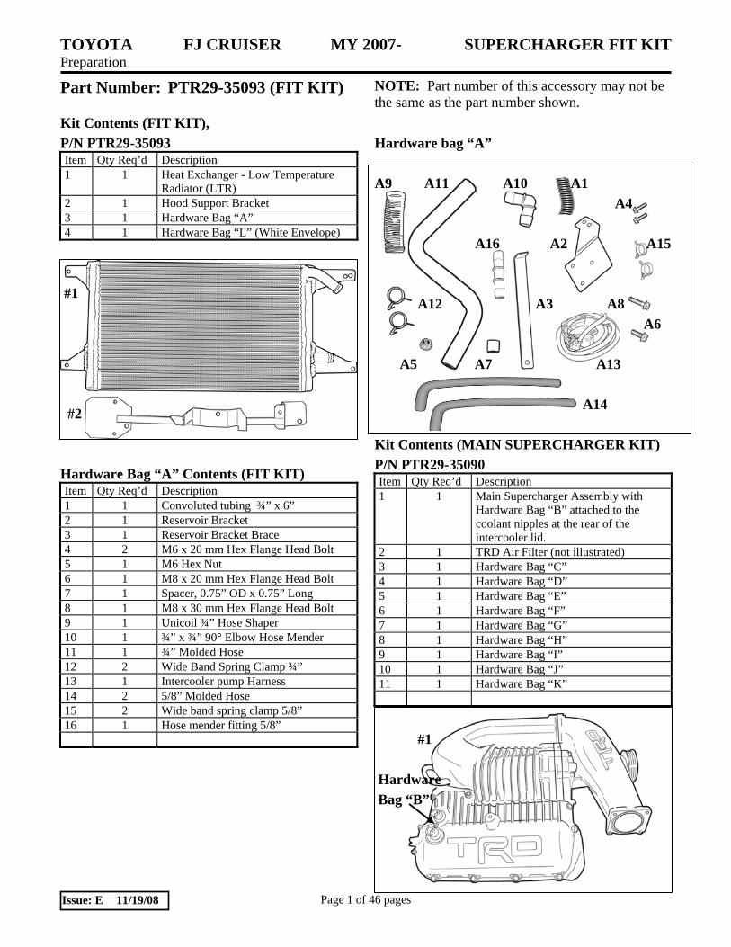
Part Number: PTR29-35093 (FIT KIT) NOTE: Part number of this accessory may not be the same as the part number shown.
Kit Contents (FIT KIT), P/N PTR29-35093 Item Qty Req’d Description 1 1 Heat Exchanger - Low Temperature
Radiator (LTR) 2 1 Hood Support Bracket 3 1 Hardware Bag “A” 4 1 Hardware Bag “L” (White Envelope)
#1 #2 Hardware Bag “A” Contents (FIT KIT) Item Qty Req’d Description 1 1 Convoluted tubing ¾” x 6” 2 1 Reservoir Bracket 3 1 Reservoir Bracket Brace 4 2 M6 x 20 mm Hex Flange Head Bolt 5 1 M6 Hex Nut 6 1 M8 x 20 mm Hex Flange Head Bolt 7 1 Spacer, 0.75” OD x 0.75” Long 8 1 M8 x 30 mm Hex Flange Head Bolt 9 1 Unicoil ¾” Hose Shaper 10 1 ¾” x ¾” 90° Elbow Hose Mender 11 1 ¾” Molded Hose 12 2 Wide Band Spring Clamp ¾” 13 1 Intercooler pump Harness 14 2 5/8” Molded Hose 15 2 Wide band spring clamp 5/8” 16 1 Hose mender fitting 5/8”
Hardware bag “A” A9 A11 A10 A1 A4 A16 A2 A15 A12 A3 A8 A6 A5 A7 A13 A14 Kit Contents (MAIN SUPERCHARGER KIT) P/N PTR29-35090 Item Qty Req’d Description 1 1 Main Supercharger Assembly with
Hardware Bag “B” attached to the coolant nipples at the rear of the intercooler lid.
2 1 TRD Air Filter (not illustrated) 3 1 Hardware Bag “C” 4 1 Hardware Bag “D” 5 1 Hardware Bag “E” 6 1 Hardware Bag “F” 7 1 Hardware Bag “G” 8 1 Hardware Bag “H” 9 1 Hardware Bag “I” 10 1 Hardware Bag “J” 11 1 Hardware Bag “K”
#1 Hardware Bag “B”

TOYOTA FJ CRUISER MY 2007- SUPERCHARGER FIT KIT Preparation
Page 2 of 46 pages Issue: E 11/19/08
Hardware Bag “B” Contents Item # Qty Req’d Description 1 6 M8 X 35 mm Reduced Shank Hex
Head Bolts
B1 Hardware Bag “C” Contents Item # Qty Req’d Description 1 1 Tensioner Bracket Assembly 2 1 5 Rib Belt 3 1 Smooth Idler Pulley 4 1 5 Rib Idler Pulley 5 1 Tensioner Strut Bracket 6 2 M10 Double Ended Stud 7 2 M10 Hex Flange Nut 8 1 M8X16mm Hex Flange Head Bolt 9 2 Short Spacers 10 1 Idler Spacer with Groove 11 1 Idler Spacer without Groove
C1 C5 C7 C2 C4 C8 C9 C3 C11 C10 C6 Hardware Bag “D” Contents Item Qty Req’d Description 1 1 Upper Idler Bracket Assembly 2 3 M8X20mm Hex Flange Head Bolt
D1 D2 Hardware Bag “E” Contents Item Qty Req’d Description 1 1 Crank Pulley 2 1 M16X70mm Hex Head bolt 3 1 M16X48mm Diam. Washer
E2 E1 E3
Hardware Bag “F” Contents Item Qty Req’d Description 1 1 Supercharger Support Bracket 2 1 Air Box Bracket 3 1 VSV Bracket 4 2 M6 Hex Flange Nut 5 1 M6 Washer 6 1 M6X16mm Hex Flange Head Bolt
F1 F4 F5 F3 F2 F6
TOYOTA FJ CRUISER MY 2007- SUPERCHARGER FIT KIT Preparation
Page 3 of 46 pages Issue: E 11/19/08
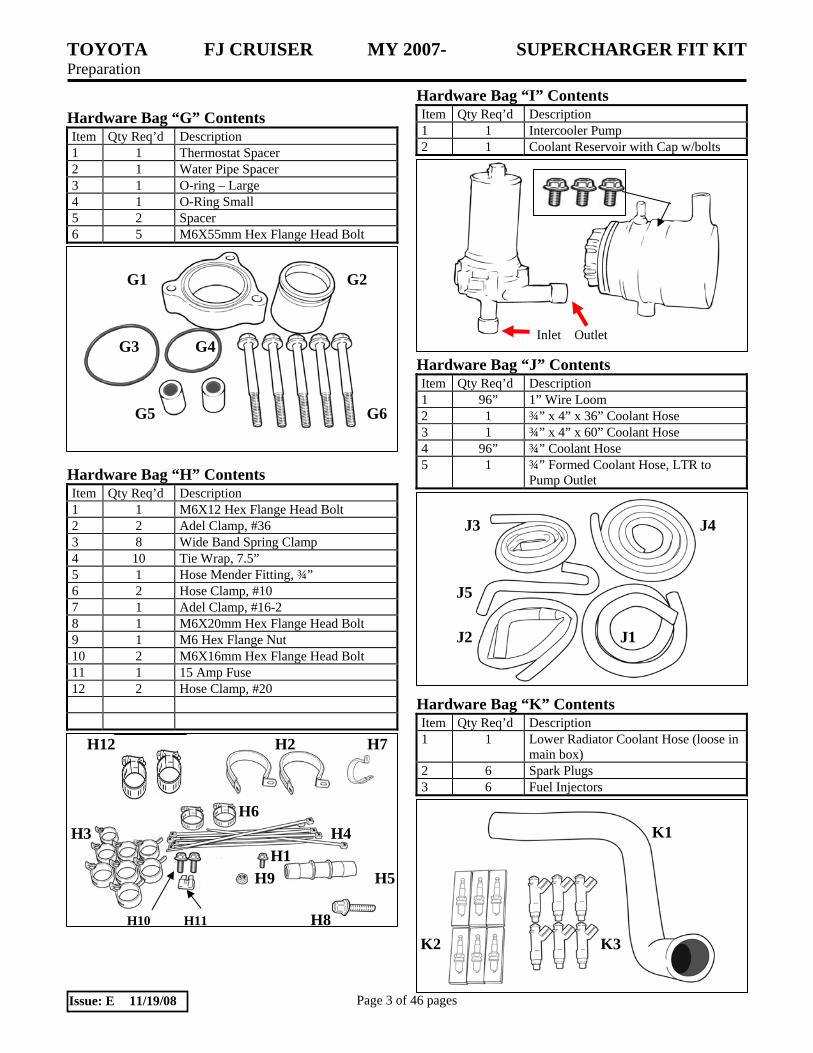
Hardware Bag “G” Contents Item Qty Req’d Description 1 1 Thermostat Spacer 2 1 Water Pipe Spacer 3 1 O-ring – Large 4 1 O-Ring Small 5 2 Spacer 6 5 M6X55mm Hex Flange Head Bolt
G1 G2 G3 G4 G5 G6
Hardware Bag “H” Contents Item Qty Req’d Description 1 1 M6X12 Hex Flange Head Bolt 2 2 Adel Clamp, #36 3 8 Wide Band Spring Clamp 4 10 Tie Wrap, 7.5” 5 1 Hose Mender Fitting, ¾” 6 2 Hose Clamp, #10 7 1 Adel Clamp, #16-2 8 1 M6X20mm Hex Flange Head Bolt 9 1 M6 Hex Flange Nut 10 2 M6X16mm Hex Flange Head Bolt 11 1 15 Amp Fuse 12 2 Hose Clamp, #20
H12 H2 H7 H6 H3 H4 H1 H9 H5 H10 H11 H8
Hardware Bag “I” Contents Item Qty Req’d Description 1 1 Intercooler Pump 2 1 Coolant Reservoir with Cap w/bolts
I1 I2
Hardware Bag “J” Contents Item Qty Req’d Description 1 96” 1” Wire Loom 2 1 ¾” x 4” x 36” Coolant Hose 3 1 ¾” x 4” x 60” Coolant Hose 4 96” ¾” Coolant Hose 5 1 ¾” Formed Coolant Hose, LTR to
Pump Outlet
J3 J4 J5 J2 J1 Hardware Bag “K” Contents Item Qty Req’d Description 1 1 Lower Radiator Coolant Hose (loose in
main box) 2 6 Spark Plugs 3 6 Fuel Injectors
K1 K2 K3
Inlet Outlet

TOYOTA FJ CRUISER MY 2007- SUPERCHARGER FIT KIT Preparation
Page 4 of 46 pages Issue: E 11/19/08
Hardware Bag “L” Contents Item Qty Req’d Description 1 2 Sticker, TRD Supercharged 2 2 Sticker, TRD Development 3 2 Sticker, Premium Fuel Warning 4 2 Sticker, TRD Red TRD Logo 5 1 Warranty certificate, TRD 6 1 Warranty Registration Card 7 1 Mirror Hanger, S/C Noise 8 1 Label, Vacuum and Belt Routing 9 1 Label, CARB D-425-28 10 1 Installation Instruction Manual
Additional Items Required For Installation Item # Quantity Reqd. Description 1 1 Main Supercharger Assembly,
P/N PTR29-35090
Conflicts Cold Air Intake System
Recommended Tools Personal & Vehicle Protection
Notes
Safety Glasses Fender Blankets Protective Gloves Special Tools Notes Toyota T.I.S. Techstream Version 4.00.017 or Later GR8 Battery Charger Crankshaft Pulley Holder SST-09213-54015 Pulley Holder Lever Arm SST-09330-00021 Installation Tools Notes Mechanic’s Hand Tools Combo wrenches & sockets ½” & 3/8” Torque Wrenches Special Chemicals Notes Anti-Seize Assembly Lube For Spark Plugs
General Applicability All Tacoma with 1GR Motor
Recommended Sequence of Application Item # Accessory 1 Not Applicable
*Mandatory
Vehicle Service Parts (may be required for reassembly) Item # Quantity Reqd. Description 1 1 Gallon* Toyota Pre-Mix Antifreeze
Coolant
* Additional coolant will be required if the original coolant is not saved and reused. Legend STOP: Damage to the vehicle may occur. Do not
proceed until process has been complied with. OPERATOR SAFETY: Use caution to avoid risk of injury. CAUTION: A process that must be carefully observed in order to reduce the risk of damage to the accessory/vehicle and to ensure a quality installation.TOOLS & EQUIPMENT: Used in Figures calls out the specific tools and equipment recommended for this process. REVISION MARK: This mark highlights a change in installation with respect to previous issue. SAFETY TORQUE: This mark indicates that torque is related to safety.

TOYOTA FJ CRUISER MY 2007- SUPERCHARGER FIT KIT Procedure
Page 5 of 46 pages Issue: E 11/19/08
Care must be taken when installing this accessory to ensure damage does not occur to the vehicle. The installation of this accessory should follow approved guidelines to ensure a quality installation. These guidelines can be found in the "Accessory Installation Practices" document. This document covers such items as:-
• Vehicle Protection (use of covers and blankets, cleaning chemicals, etc.). • Safety (eye protection, rechecking torque procedure, etc.). • Vehicle Disassembly/Reassembly (panel removal, part storage, etc.). • Electrical Component Disassembly/Reassembly (battery disconnection, connector removal, etc.). • The TIS Repair Manual can be referenced for additional details.
Please see your Toyota dealer for the latest revision of this document, or visit the TIS website.
1. Installation Review and Vehicle Preparation.
(a) Review the entire instruction instructions provided before beginning the installation
(b) Review the parts list/kit contents to ensure that all parts are present before beginning the installation. If any items are missing contact Technical Support at (800) 688-5912 before proceeding.
(c) Remove any low-octane fuel from the vehicle. Ensure that ONLY 91 octane or higher unleaded gasoline is used.
(d) Place the vehicle onto vehicle hoist.
(e) Protect the vehicle with protection blankets over the fenders and front of the vehicle.
(f) Disconnect and remove the battery.
(g) When draining the cooling system into a clean container in Step 7, save this coolant as it will be reused. CAUTION: To avoid the danger of being burned, do not remove the radiator cap while the engine and radiator are still hot. Thermal expansion will cause the hot engine coolant and steam to blow out from the radiator.
(h) All parts that are removed and not reused should be saved for the customer, i.e., “discard” means to save for the customer.

TOYOTA FJ CRUISER MY 2007- SUPERCHARGER FIT KIT Procedure
Page 6 of 46 pages Issue: E 11/19/08
Fig 2-2
Fig 2-3
Fig 2-4
Fig 2-1
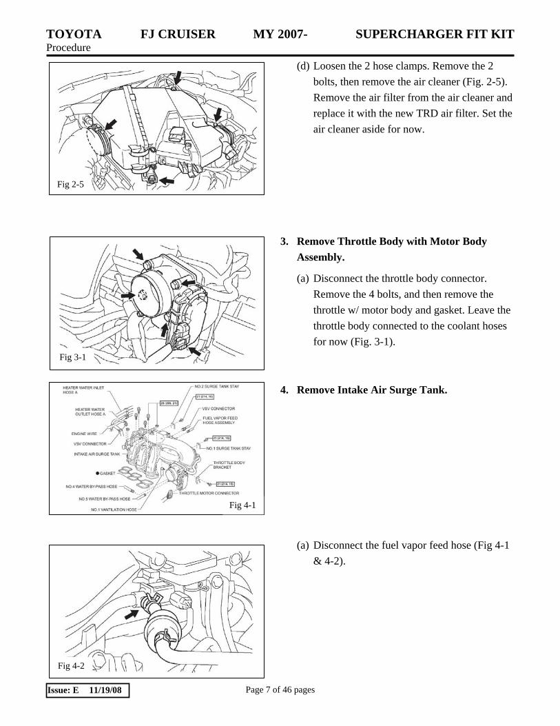
2. Remove Air Cleaner Assembly.
(a) Remove the engine V-bank cover by removing the two acorn nuts (Figs 2-1 & 2-2).
(b) Disconnect the ventilation hose No. 2 (Fig 2-3).
(c) Disconnect the vacuum hose. Disconnect the mass air flow meter connector. Remove the 2 wire harness clamps (Fig. 2-4)
TOYOTA FJ CRUISER MY 2007- SUPERCHARGER FIT KIT Procedure
Page 7 of 46 pages Issue: E 11/19/08
Fig 2-5
Fig 3-1
Fig 4-1
Fig 4-2
(d) Loosen the 2 hose clamps. Remove the 2 bolts, then remove the air cleaner (Fig. 2-5). Remove the air filter from the air cleaner and replace it with the new TRD air filter. Set the air cleaner aside for now.
3. Remove Throttle Body with Motor Body Assembly.
(a) Disconnect the throttle body connector. Remove the 4 bolts, and then remove the throttle w/ motor body and gasket. Leave the throttle body connected to the coolant hoses for now (Fig. 3-1).
4. Remove Intake Air Surge Tank.
(a) Disconnect the fuel vapor feed hose (Fig 4-1 & 4-2).
TOYOTA FJ CRUISER MY 2007- SUPERCHARGER FIT KIT Procedure
Page 8 of 46 pages Issue: E 11/19/08
Fig 4-3
Fig 4-4
Fig 4-5
Fig 4-6
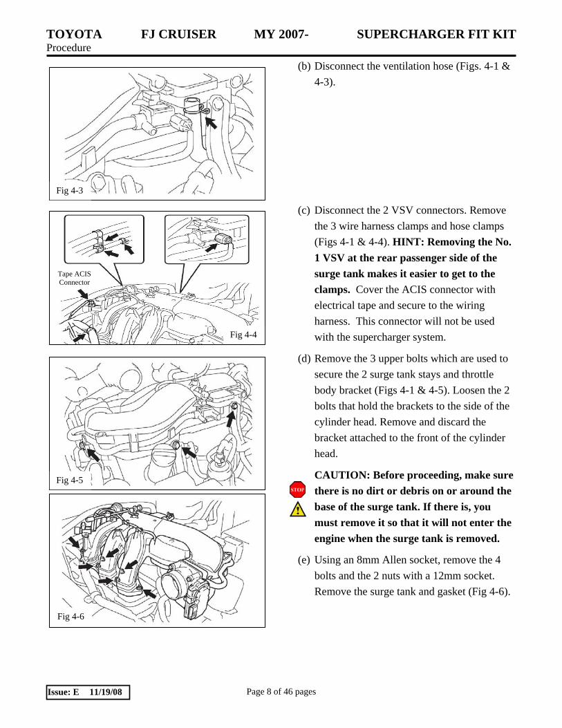
(b) Disconnect the ventilation hose (Figs. 4-1 & 4-3).
(c) Disconnect the 2 VSV connectors. Remove the 3 wire harness clamps and hose clamps (Figs 4-1 & 4-4). HINT: Removing the No. 1 VSV at the rear passenger side of the surge tank makes it easier to get to the clamps. Cover the ACIS connector with electrical tape and secure to the wiring harness. This connector will not be used with the supercharger system.
(d) Remove the 3 upper bolts which are used to secure the 2 surge tank stays and throttle body bracket (Figs 4-1 & 4-5). Loosen the 2 bolts that hold the brackets to the side of the cylinder head. Remove and discard the bracket attached to the front of the cylinder head.
CAUTION: Before proceeding, make sure there is no dirt or debris on or around the base of the surge tank. If there is, you must remove it so that it will not enter the engine when the surge tank is removed.
(e) Using an 8mm Allen socket, remove the 4 bolts and the 2 nuts with a 12mm socket. Remove the surge tank and gasket (Fig 4-6).
Tape ACIS Connector

TOYOTA FJ CRUISER MY 2007- SUPERCHARGER FIT KIT Procedure
Page 9 of 46 pages Issue: E 11/19/08
Fig 4-7
Fig 5-3
Fig 5-2
Clamp
Fig 4-8
Fig 5-1
(f) Wipe off the engine surface and apply tape to cover the intake ports (Fig 4-7).
(g) After the ports are taped over, using an E-5 internal Torx socket, remove the 2 studs from the intake manifold (Fig 4-8).
5. Fuel Injector Replacement.
Warning: The Fuel System is under High Pressure. Use Safety Glasses and Fuel Compatible Gloves to prevent Personal Injury
(a) For the No. 1 fuel pipe, remove the fuel pipe clamp. Pinch the tube connector, and pull the fuel pipe out of the connector as shown (Figs 5-1, 5-2, 5-3). Repeat for the No. 2 fuel pipe.
NOTICE: • Remove any dirt and foreign objects
from the connectors before performing this work.
• Do not allow any scratches or foreign objects on the parts when disconnecting, as the fuel tube connector has the O-ring that seals the pipe.
• Perform this work by hand. Do not use any tools.
• Do not forcibly bend, twist or turn the nylon tube.
• Protect the disconnected parts by covering them with a plastic bag after disconnecting them.
• If the fuel tube connector and pipe are stuck, push and pull to release them.

TOYOTA FJ CRUISER MY 2007- SUPERCHARGER FIT KIT Procedure
Page 10 of 46 pages Issue: E 11/19/08
Fig 5-4
Fig 5-5
Fig 5-6
Fig 5-7
(b) Disconnect the 6 fuel injector connectors. Remove the 6 bolts and fuel delivery pipe together with the 6 fuel injectors (Figs 5-1 & 5-4).
(c) Pull the 6 injectors out of the delivery pipe
(Fig 5-5). Discard the injectors as they will be replaced with new higher flow injectors. The old injectors should be saved for the customer. NOTE: The new injectors (K3) have Mustard colored bodies, while the old injectors have Blue colored bodies.
(d) Install a light coat of spindle oil or gasoline
to the O-ring on the top of each new injector. While turning the fuel injector left or right, install it onto the fuel delivery pipe positioning the connector facing outward (Fig 5-6). Repeat for all six new injectors.
(e) Place the fuel delivery pipe together with the
new injectors on the intake manifold. Provisionally install the 6 bolts, which are used to hold the delivery pipe, onto the intake manifold. Check to see that the injectors rotate smoothly. Position the injector connectors facing outward. Tighten the 6 bolts. Torque: 15 Nm (11 ft lbf) (Fig 5-7).
(f) Reconnect the 6 fuel injector connectors.

TOYOTA FJ CRUISER MY 2007- SUPERCHARGER FIT KIT Procedure
Page 11 of 46 pages Issue: E 11/19/08
Fig 5-8
Fig 6-1
Fig 6-2
Fig 6-3
(g) Reconnect the No. 1 and No. 2 fuel pipe sub-assemblies to the fuel delivery pipe connectors by pushing together until the connector makes a “click” sound. After connecting, check that the pipe and connector are securely connected by pulling on them. Reinstall the clamps on each connector.
(h) To ensure clearance to the supercharger
manifold, pry the wire loom retainer up off the stud on the LH cylinder head cover (Fig 5-8). NOTE: Do not omit this step.
6. Spark Plug Replacement
(a) Unplug the electrical connector from each of the 6 ignition coils (Fig 6-1).
(b) Remove the 6 bolts, then remove the 6
ignition coils (Fig 6-2). (c) Remove the 6 spark plugs and discard them
in a box for the customer. New colder plugs will be installed (Fig 6-3). CAUTION: Blow any dirt or debris from around the spark plugs before removing them.
Wear Safety Glasses when using Compressed air.

TOYOTA FJ CRUISER MY 2007- SUPERCHARGER FIT KIT Procedure
Page 12 of 46 pages Issue: E 11/19/08
Fig 6-4
Old Plug New Plug
Fig 7-1
Fig 7-3
Fig 7-2
(d) Install the 6 new spark plugs (K2). A little
anti-seize on the plug threads will prevent seizing in the future (Fig 6-4). Torque: 20 Nm (15 ft lbf)
Set Spark Plug Gap at 0.8 mm (0.032”) (e) Reinstall the ignition coils and the bolts.
Torque: 10 Nm (7.4 ft lbf)
7. Coolant, Fan and Shroud Removal.
(a) Remove the 7 plastic clips from the black plastic seal cover at the top of the radiator and set it aside for reinstallation later (Fig 7-1).
(b) Remove 4 bolts, then remove the No.1
engine under cover (Fig 7-2). (c) Drain Engine Coolant
CAUTION: To avoid the danger of being burned, do not remove the radiator cap while the engine and radiator are still hot. Thermal expansion will cause hot engine coolant and steam to blow out from the radiator. i. Remove the service hole cover from the
engine under cover. NOTE: On some vehicles it may be necessary to remove the skid plate.
ii. Install a vinyl hose onto the drain on the radiator side (Fig 7-3) and secure with tape.

TOYOTA FJ CRUISER MY 2007- SUPERCHARGER FIT KIT Procedure
Page 13 of 46 pages Issue: E 11/19/08
Fig 7-4
Fig 7-5
Fig 7-6
Fig 7-7
iii. Loosen the three drain plugs on the engine and radiator and drain the coolant into a clean container (Fig 7-4). Save the coolant as it will be reused.
iv. Remove the radiator cap.
v. Drain the coolant from the reservoir tank.
vi. Tighten the three drain plugs. Torque: 13 Nm (9.0 ft lbf) for the engine
vii. Remove the vinyl hose from the radiator.
(d) Remove the top radiator hose (Fig 7-5). Save for reuse.
(e) Remove the four nuts that attach the
fan/clutch to the fan pulley (Fig 7-6). Leave the fan in place for now.
(f) Remove the two bolts from the top corners of
the fan shroud (Fig 7-7) and the bottom corner of the coolant overflow tank.
(g) Disconnect the coolant overflow tube from
the radiator (Fig 7-5). If the vehicle has an oil cooler, it will be necessary to remove a clip holding the fluid lines to the shroud.

TOYOTA FJ CRUISER MY 2007- SUPERCHARGER FIT KIT Procedure
Page 14 of 46 pages Issue: E 11/19/08
Fig 7-8
Fig 7-9
Fig 8-1
Fig 8-2
(h) Carefully remove the fan and shroud together so you do not damage the radiator (Fig 7-8). Note: Tape a piece of cardboard (about the size of the radiator) to the back side of the radiator to prevent damage during subsequent steps.
(i) Reinstall two of the fan nuts (finger tight) so
the fan pulley will not fall off (Fig 7-9). (j) Remove the lower radiator hose. The hose
will not be reused.
8. Installation of the Auxiliary Drive Pulleys. (a) While releasing the belt tension by turning
the belt tensioner counterclockwise, remove the belt from the power steering pump pulley (Figs 8-1 & 8-2). NOTE: It is not necessary to completely remove the belt.

TOYOTA FJ CRUISER MY 2007- SUPERCHARGER FIT KIT Procedure
Page 15 of 46 pages Issue: E 11/19/08
Fig 8-3
Fig 8-6
Fig 8-4
Forward
Fig 8-5
Forward
(b) Remove Idler No. 1 and discard the bolt (Figs 8-2 & 8-3).
(c) Install the one of the double ended M10 studs
(C6) and snug it in place with a flat blade screwdriver. Reinstall the original smooth pulley, the idler spacer without a groove (C11), the 5 rib idler pulley (C4) (snap ring facing the engine), and one of the short spacers (C9) (Fig 8-4). Temporarily install the M10 nut (C7) finger tight.
(d) Remove Idler No. 2 and discard the bolt
(Figs 8-2 & 8-3). Keep the thin step washer and pulley for the next step. NOTE: Do not mistake Idler No. 2 for the tensioner pulley.
(e) Install the other double ended M10 stud (C6)
and snug it in place with a flat blade screwdriver. Reinstall the original smooth pulley and thin step washer, the idler spacer with a groove (C10), the smooth idler pulley (C3), and the other short spacer (C9) (Fig 8-5). Temporarily install the M10 nut (C7) finger tight.
(f) Reinstall the fan and generator belt (Fig 8-2). (g) Using an impact gun, remove the bolt and
washer that secures the crankshaft pulley (Fig 8-6). Discard the bolt and washer. Do not remove the pulley.

TOYOTA FJ CRUISER MY 2007- SUPERCHARGER FIT KIT Procedure
Page 16 of 46 pages Issue: E 11/19/08
Fig 8-7
Fig 8-8
Fig 9-1
Fig 9-2
(h) Install the supplied crankshaft pulley (E1) in front of the existing crankshaft pulley making certain that the dowel pin in the new pulley is aligned with the key way in the existing pulley using the new supplied bolt (E2) and washer (E3) (Fig 8-7). Torque: 277 Nm (204 ft lbf)
SST 09213-54015 and SST 09330-00021 (i) Install the blower drive belt (C2) as shown
(Fig 8-8).
9. Installation of the Auxiliary Tensioner Assembly. (a) Remove the 2 M10 nuts and then install the
belt tensioner assembly (C1) onto the two double ended studs previously installed (Fig 9-1 & 9-2). Make sure both sides of the blower drive belt are free between the tensioner pulley and the upper idler pulley. Reinstall the two M10 nuts (C7) finger tight.

TOYOTA FJ CRUISER MY 2007- SUPERCHARGER FIT KIT Procedure
Page 17 of 46 pages Issue: E 11/19/08
Fig 9-3
Fig 9-4
Fig 10-1
Fig 10-2
(b) Remove the top/forward AC compressor mounting bolt (Fig 9-3). CAUTION: Do not remove the bolts that attach the AC lines to the compressor.
(c) Using the bolt removed in step 9-b, attach
one end of the tensioner support bracket (C5) to the AC compressor finger tight (Fig 9-4). NOTE: Notice that the bracket goes behind the belt.
(d) Attach the other end of the strut bracket to
the belt tensioner bracket using an M8x16 bolt (C8) (Fig 9-4). Tighten the two M10 nuts, then M8x16 bolt, and finally the AC Compressor bolt.
Torque: 39 Nm (29 ft lbf) for M10 nuts
Torque: 25 Nm (18 ft lbf) for M8 bolts
(e) Be sure the blower drive belt is on the bottom of the tensioner pulley (Fig 9-1).
10. Installation of the Water Manifold Spacers.
(a) Remove 2 throttle body bypass hoses, 2 small bypass hoses, and the larger bypass hose that are attached to the thermostat water manifold (Fig 10-1). It is suggested that a diagram be made showing where all the hoses go. Some vehicles may also have 2 oil cooler hoses to remove.
(b) Remove and discard the 5 bolts attaching the thermostat water manifold to the engine. Make sure the 2 O-rings remain on the engine (Fig 10-2).

TOYOTA FJ CRUISER MY 2007- SUPERCHARGER FIT KIT Procedure
Page 18 of 46 pages Issue: E 11/19/08
Fig 10-4
O-Ring Water Pipe Spacer
Fig 10-3
Fig 10-5
Apply grease
Fig 10-6
(c) Install the small O-ring (G4) onto the new water pipe spacer (G2). Apply a small amount of grease to the O-ring and inside the bore of the thermostat water manifold (Fig 10-3).
(d) Install the water pipe spacer into the
thermostat water manifold (Fig 10-4). (e) Apply a small amount of grease to the inside
bore of the water pipe spacer (Fig 10-5). (f) Install 3 of the new M6x55 bolts (G6) in the
thermostat water manifold (Fig 10-6).
TOYOTA FJ CRUISER MY 2007- SUPERCHARGER FIT KIT Procedure
Page 19 of 46 pages Issue: E 11/19/08
Fig 10-7
Fig 10-8
Fig 10-9
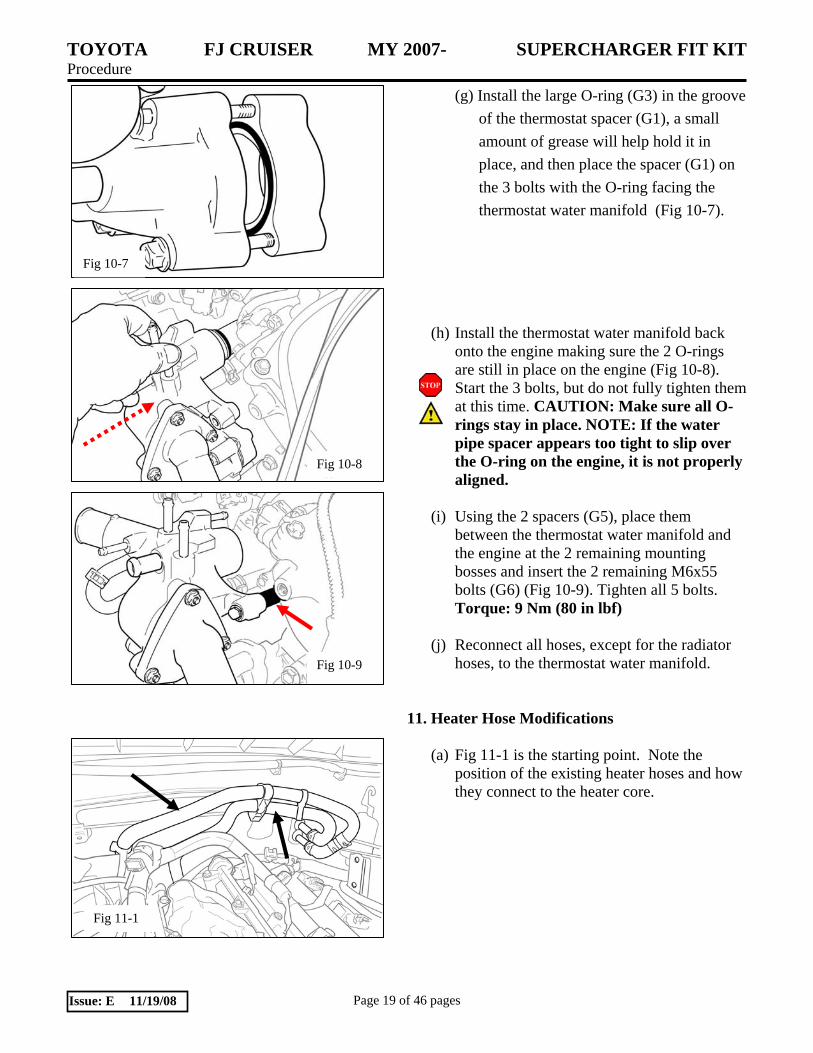
(g) Install the large O-ring (G3) in the groove of the thermostat spacer (G1), a small amount of grease will help hold it in place, and then place the spacer (G1) on the 3 bolts with the O-ring facing the thermostat water manifold (Fig 10-7).
(h) Install the thermostat water manifold back
onto the engine making sure the 2 O-rings are still in place on the engine (Fig 10-8). Start the 3 bolts, but do not fully tighten them at this time. CAUTION: Make sure all O-rings stay in place. NOTE: If the water pipe spacer appears too tight to slip over the O-ring on the engine, it is not properly aligned.
(i) Using the 2 spacers (G5), place them
between the thermostat water manifold and the engine at the 2 remaining mounting bosses and insert the 2 remaining M6x55 bolts (G6) (Fig 10-9). Tighten all 5 bolts. Torque: 9 Nm (80 in lbf)
(j) Reconnect all hoses, except for the radiator
hoses, to the thermostat water manifold.
11. Heater Hose Modifications
(a) Fig 11-1 is the starting point. Note the position of the existing heater hoses and how they connect to the heater core.
Fig 11-1

TOYOTA FJ CRUISER MY 2007- SUPERCHARGER FIT KIT Procedure
Page 20 of 46 pages Issue: E 11/19/08
Fig 11-2
Remove and discard this hose bracket
KEEP
Fig 11-3
(b) Disconnect the two heater hoses from the heater core nipples. (Fig 11-2)
(c) Remove and retain the 4 hose clamps and the one mender for use later. (Fig 11-2)
(d) Remove the hose spacers, discarding the
larger one and keeping the smaller one. (Fig 11-3)
(e) Remove the metal bracket supporting the wire harness. Make certain that the metal bracket is not attached to either the heater hoses or the wiring harness (Fig 11-3).
(f) Fabricate the hoses shown in Fig11-4 from the two new hoses and one mender that came with the kit ( A16, A14) and the 4 hose clamps, one mender, and one spacer salvaged from steps (c) and (d).
Fig 11-4

TOYOTA FJ CRUISER MY 2007- SUPERCHARGER FIT KIT Procedure
Page 21 of 46 pages Issue: E 11/19/08
Fig 12-1
(g) Install the 2.5” x 9.5” hose to the top heater
core nipple. Lay it across the proper existing hose. Cut the existing hose to length. Complete the connections. (Fig 11-5)
(h) Install the new 2.5” x 14” hose to the bottom heater core nipple. Lay it across the proper existing hose. Cut the existing hose to length. Complete the connections. Apply ¾” x 6” convoluted tubing (A1) on either heater hose for abrasion protection. (Fig 11-6)
12. Installation of the Support Bracket (a) On the driver’s side (left) of the engine,
remove the rear intake manifold support bracket (surge tank stay No. 2) and replace it with the new support bracket (F1) (Fig 12-1). Note: the original bracket is stamped with a “C” and the new bracket is stamped with a “B”. Leave the attaching bolt finger tight. Make sure you use the same threaded bolt hole on the engine.
Fig 11-6
Fig 11-5
TOP NIPPLE

TOYOTA FJ CRUISER MY 2007- SUPERCHARGER FIT KIT Procedure
Page 22 of 46 pages Issue: E 11/19/08
Fig 13-2
Fig 13-3
Fig 13-1
Fig 13-4
13. Installation of the Vacuum Switching Valve (VSV) Assembly and Hoses. (a) Remove the VSV from the left rear side of
the original intake manifold (surge tank) (Fig 13-1). Keep the VSV and bolt for the next step.
(b) Attach the VSV to the supplied VSV Bracket
(F3) using the stock bolt and a supplied M6 nut (F4) (Fig 13-2).
(c) Mount the VSV/VSV bracket subassembly to
the front stud of the oil filler cap housing. Remove the stock nut, install the M6 washer (F5), the bracket-valve assembly, and reinstall the nut (Fig 13-2). Torque: 9 Nm (80 in lbf)
(d) Plug in the electrical connector to the VSV
(Fig 13-3).
(e) The fuel vapor hoses were originally connected to the VSV as shown (Fig 13-4). Disconnect these hoses and reconnect them as shown in (Fig 13-5 & 13-6). Hose end A attaches to the hard vapor line (Fig 13-6). Leave hose end B loose for now. Hose end B will be attached to the supercharger in a later step.

TOYOTA FJ CRUISER MY 2007- SUPERCHARGER FIT KIT Procedure
Page 23 of 46 pages Issue: E 11/19/08
Fig 14-1
Fig 14-2
Fig 13-5
A
B
Fig 13-6
Leave B loose
Attach end A to the hard vapor line
14. Preparation for the Supercharger Housing Installation. (a) Remove the intake port gasket and throttle
body O-ring from the intake air surge tank (Fig 14-1). Retain these parts for the next step.
(b) Install the intake manifold gasket and throttle
body O-ring in the supercharger housing (Fig 14-2). The molded gasket and O-ring should fit snugly in the grooved recesses in the housing.
TOYOTA FJ CRUISER MY 2007- SUPERCHARGER FIT KIT Procedure
Page 24 of 46 pages Issue: E 11/19/08
Fig 14-4
Fig 14-5
When installed, the bolts will float on the reduced diameter shanks.
Fig 15-1
Fig 14-3
Do Not Remove this bolt
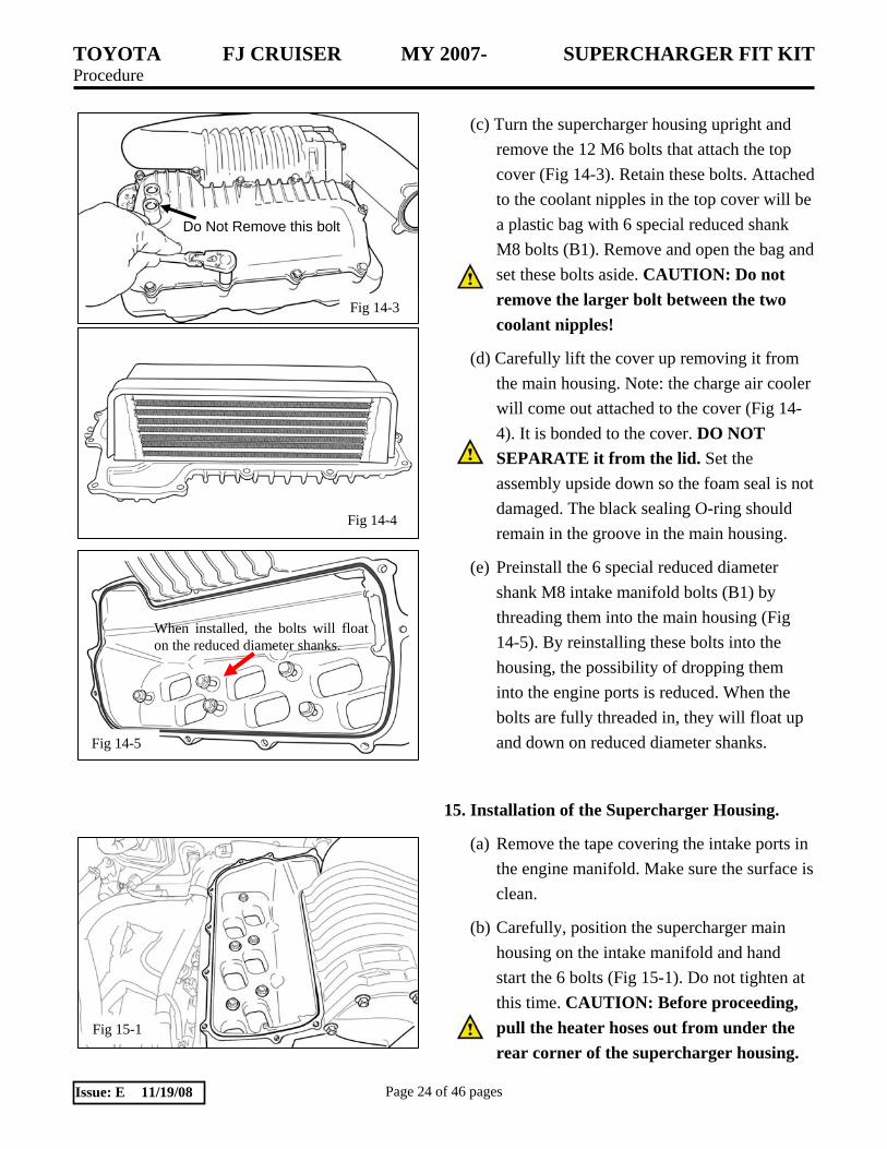
(c) Turn the supercharger housing upright and
remove the 12 M6 bolts that attach the top cover (Fig 14-3). Retain these bolts. Attached to the coolant nipples in the top cover will be a plastic bag with 6 special reduced shank M8 bolts (B1). Remove and open the bag and set these bolts aside. CAUTION: Do not remove the larger bolt between the two coolant nipples!
(d) Carefully lift the cover up removing it from the main housing. Note: the charge air cooler will come out attached to the cover (Fig 14-4). It is bonded to the cover. DO NOT SEPARATE it from the lid. Set the assembly upside down so the foam seal is not damaged. The black sealing O-ring should remain in the groove in the main housing.
(e) Preinstall the 6 special reduced diameter shank M8 intake manifold bolts (B1) by threading them into the main housing (Fig 14-5). By reinstalling these bolts into the housing, the possibility of dropping them into the engine ports is reduced. When the bolts are fully threaded in, they will float up and down on reduced diameter shanks.
15. Installation of the Supercharger Housing.
(a) Remove the tape covering the intake ports in the engine manifold. Make sure the surface is clean.
(b) Carefully, position the supercharger main housing on the intake manifold and hand start the 6 bolts (Fig 15-1). Do not tighten at this time. CAUTION: Before proceeding, pull the heater hoses out from under the rear corner of the supercharger housing.

TOYOTA FJ CRUISER MY 2007- SUPERCHARGER FIT KIT Procedure
Page 25 of 46 pages Issue: E 11/19/08
Fig 15-2
Fig 15-3
Fig 15-4
Supercharger Pulley
Tensioner
Idler
Idler
Crank Pulley
Fig 16-1
(c) Install the original 2 bolts that attach the support brackets (2 surge tank stays) to the supercharger housing Fig 15-2). Do not tighten.
(d) Using the 3 M8 bolts (D2), install the upper idler bracket assembly (D1) to supercharger housing (2 places) and the engine cylinder head boss (1 place) Fig 15-3). Do not tighten.
(e) Tighten all fasteners starting with the intake manifold, then the side support brackets, and finally the idler pulley assembly. Torque: 28 Nm (21 ft lbf) (Fig 15-1 ~ 15-3)
(f) After checking to make certain the large O-ring is properly seated in the groove in the main housing, carefully re-install the supercharger housing top cover by lowering it straight down. Fasten with the original 12 M6 bolts. Torque: 12 Nm (9 ft lbf) CAUTION: If the O-ring ends have separated, place a small spot of black RTV over the area where they join before placing the lid in position.
(g) Finish installing the supercharger belt drive making sure the routing is correct (Fig 15-4).
16. Installation of the Fan and Shroud Assembly, Hoses and Throttle Body.
(a) Re-install the fan and radiator shroud and tighten all fasteners. Torque: 21 Nm (15 ft lbf) fan nuts
Torque: 5 Nm (44 in lbf) shroud bolts
(b) Re-install the top radiator hose.

TOYOTA FJ CRUISER MY 2007- SUPERCHARGER FIT KIT Procedure
Page 26 of 46 pages Issue: E 11/19/08
Fig 16-2
Fig 17-1
Fig 17-2
Fig 17-3
(c) Install the throttle body to the supercharger housing and re-connect the coolant hoses to the thermostat water manifold (Fig 16-1). Torque: 11 Nm (8 ft lbf)
(d) Using the new screw clamps, install the new lower radiator hose (K1) (Fig 16-2). CAUTION: Turn the clamps so they do not hit the fan.
17. Preparation for the Low Temperature Radiator (LTR).
(a) Remove the radiator grill (Fig 17-1).
(i) Remove the 2 screws.
(ii) Using a clip remover, remove the 2 clips.
(iii) Disengage the 5 clips and remove the radiator grill.
(b) Apply protective tape (Fig 17-2).
(c) Remove the 5 clips (Fig 17-3).
TOYOTA FJ CRUISER MY 2007- SUPERCHARGER FIT KIT Procedure
Page 27 of 46 pages Issue: E 11/19/08
Fig 17-4
Fig 17-5
Fig 17-6
Fig 17-7
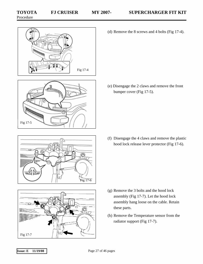
(d) Remove the 8 screws and 4 bolts (Fig 17-4).
(e) Disengage the 2 claws and remove the front bumper cover (Fig 17-5).
(f) Disengage the 4 claws and remove the plastic hood lock release lever protector (Fig 17-6).
(g) Remove the 3 bolts and the hood lock assembly (Fig 17-7). Let the hood lock assembly hang loose on the cable. Retain these parts.
(h) Remove the Temperature sensor from the radiator support (Fig 17-7).

TOYOTA FJ CRUISER MY 2007- SUPERCHARGER FIT KIT Procedure
Page 28 of 46 pages Issue: E 11/19/08
Fig 17-9
Fig 17-8
Fig 17-11
(i) Disconnect the electrical connector and remove the horns (Fig 17-8). Retain these parts.
(j) Remove the 3 bolts that attach the hood latch support bracket to the bumper and radiator supports (Fig 17-9). Save these fasteners. The bracket will be replaced by the new bracket supplied in the kit (#2).
(k) The AC condenser is mounted at 4 locations, 2 at the top and 2 half way down. Locate the two No. 2 cooler condenser cushions and remove the upper bolt from each (Fig 17-10). Save these bolts.
(l) Remove and save the bolts from the two upper No. 1 cooler condenser cushions (Fig 17-11).
Fig 17-10

TOYOTA FJ CRUISER MY 2007- SUPERCHARGER FIT KIT Procedure
Page 29 of 46 pages Issue: E 11/19/08
Fig 18-1
Fig 18-4
Fig 18-2
Fig 18-3
18. Installation of the Low Temperature Radiator (LTR), Intercooler Pump, Latch, and Horn Assemblies.
(a) Place the LTR in position in front of the AC condenser. (Fig 18-1). The upper and lower mounting tabs on the LTR align with the bolts removed in steps 17j & 17k.
(b) Reinstall the original condenser mounting bolts (Fig 18-2 & 18-3) capturing the LTR mounting tabs between the AC condenser and the condenser cushions. Torque: 5.5 Nm (49 in lbf)
(c) Mount the intercooler pump (I1) to the new hood support bracket (#2) using the two large #35 Adel Clamps ( H2) and M6X16 Hex Flange Head Bolts (H10) ( Fig 18-4). Do not tighten the fasteners at this time. HINT: It helps to hand shape the Adel Clamps to the shape of the pump.

TOYOTA FJ CRUISER MY 2007- SUPERCHARGER FIT KIT Procedure
Page 30 of 46 pages Issue: E 11/19/08
Fig 18-8
Fig 18-5
Fig 18-6
Remove
Fig 18-7
(d) Install the new hood support bracket/pump assembly with the original fasteners (Fig 18-5). Torque: 8 Nm (71 in lbf)
(e) Reinstall the hood lock assembly (Fig 18-6). Torque: 8 Nm (71 in lbf)
(f) Reinstall the temperature sensor to the new hood latch bracket (Fig 18-6).
(g) Trim the plastic hood lock release lever protector as shown (Fig 18-7).
(h) Reinstall the hood lock release lever protector (Fig 18-8).

TOYOTA FJ CRUISER MY 2007- SUPERCHARGER FIT KIT Procedure
Page 31 of 46 pages Issue: E 11/19/08
Fig 18-9
Fig 18-10
Fig 19-2
Fig 19-1
(i) Re-mount the horn with the spacer (A7), M8X30 mm bolt (A8) as shown (Fig 18-9). Note: This is to space the horn out away from the LTR. Torque: 9.8 Nm (7 ft lbf) Reconnect the electrical connector to the horn.
(j) After making sure the outlet on the pump points straight up, tighten the mounting bolts. Torque: 12 Nm (9 ft lbf)
(k) Slide a wide band spring clamp (H3) approximately 2” onto each end of the LTR to pump formed coolant hose (J5). Install this hose to the lower outlet on the LTR and the pump outlet and position each clamp to hold it in place (Fig 18-10).
19. Installation of the Intercooler Tank and Hoses.
(a) There are 2 holes in the lifting bracket for the brake master cylinder (Fig 19-1). The will be used to mount the intercooler coolant reservoir. The forward most of the two holes has an M6 weld nut attached to the lifting bracket.
(b) Using 2 M6x20 bolts (A4) and 1 M6 nut (A5), mount the intercooler reservoir bracket (A2) to the 2 holes in the lifting bracket (Fig 19-2). Torque: 5.5 Nm (49 in lbf)

TOYOTA FJ CRUISER MY 2007- SUPERCHARGER FIT KIT Procedure
Page 32 of 46 pages Issue: E 11/19/08
Fig 19-3
Fig 19-4
Fig 19-5
90° Tab
FOR MANUAL TRANSMISSIONS
(c) On the driver’s side inner fender panel, there is a reinforcing plate to which the clutch reservoir is attached. Remove the M8 bolt shown (Fig 19-3).
(d) Attach the reservoir bracket brace (A3) to the threaded hole where the bolt was removed in step 19c using the M8x20 bolt (A6) (Fig 19-4). Torque: 8 Nm (71 in lbf) The other end of the brace will attach to the upper driver’s side hole in the reservoir bracket when the reservoir is mounted.
(e) Using 3 M6x12 bolts (I2), mount the intercooler reservoir tank (I2) to the reservoir bracket (Fig 19-4) making sure you capture the brace from step 19b. Torque: 4 Nm (35 in lbf)
FOR AUTOMATIC TRANSMISSIONS
(f) There will either be an open M8 threaded hole in the driver’s side inner fender panel, or it may have a tab on a bracket in the threaded hole as shown (Fig 19-5).
(g) If the bracket is present, remove and flatten the tab as shown (Fig 19-6).
(h) Attach the reservoir bracket brace (A3) to the threaded hole using the M8x20 bolt (A6) (Fig 19-4). Torque: 8 Nm (71 in lbf) The other end of the brace will attach to the upper driver’s side hole in the reservoir bracket when the reservoir is mounted (Fig 19-7).

TOYOTA FJ CRUISER MY 2007- SUPERCHARGER FIT KIT Procedure
Page 33 of 46 pages Issue: E 11/19/08
Fig 19-7
2.5”
2.5”
Fig 19-9
Fig 19-8
Reservoir outlet to pump inlet.
90° Elbow
Short Leg Wire Loom
Fig 19-10
(i) Remount the bracket as shown (Fig 19-7).
(j) Using 3 M6x12 bolts (I2), mount the intercooler reservoir tank (I2) to the reservoir bracket (Fig 19-4) making sure you capture the brace from step 19h. Torque: 4 Nm (35 in lbf)
(k) Before proceeding with the remainder of the hose plumbing, study the hose routing (Fig 19-8).
(l) Take the molded hose (A11) and mark and cut it as shown (Fig 19-9). When you cut and remove 2.5” from each leg, you should end up with 1” on the short leg.
(m) Insert the 90° elbow (A10) into the long leg of the modified molded hose (A11). Attach the 96” length of the straight ¾” hose (J4) to the other end of the 90° elbow and secure with 2 Wide band Spring clamps (H3). Cut a 36” length of 1” split wire loom and slide it on the end ¾” straight hose (Fig 19-10).
TOYOTA FJ CRUISER MY 2007- SUPERCHARGER FIT KIT Procedure
Page 34 of 46 pages Issue: E 11/19/08
Fig 19-11
90° Elbow
Short Leg
Fig 19-12a
Inlet
Fig 19-13
Outlet
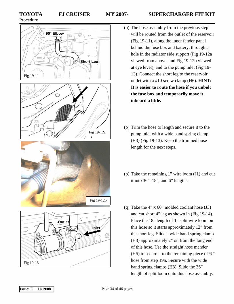
(n) The hose assembly from the previous step will be routed from the outlet of the reservoir (Fig 19-11), along the inner fender panel behind the fuse box and battery, through a hole in the radiator side support (Fig 19-12a viewed from above, and Fig 19-12b viewed at eye level), and to the pump inlet (Fig 19-13). Connect the short leg to the reservoir outlet with a #10 screw clamp (H6). HINT: It is easier to route the hose if you unbolt the fuse box and temporarily move it inboard a little.
(o) Trim the hose to length and secure it to the pump inlet with a wide band spring clamp (H3) (Fig 19-13). Keep the trimmed hose length for the next steps.
(p) Take the remaining 1” wire loom (J1) and cut it into 36”, 18”, and 6” lengths.
(q) Take the 4” x 60” molded coolant hose (J3) and cut short 4” leg as shown in (Fig 19-14). Place the 18” length of 1” split wire loom on this hose so it starts approximately 12” from the short leg. Slide a wide band spring clamp (H3) approximately 2” on from the long end of this hose. Use the straight hose mender (H5) to secure it to the remaining piece of ¾” hose from step 19n. Secure with the wide band spring clamps (H3). Slide the 36” length of split loom onto this hose assembly.
Fig 19-12b

TOYOTA FJ CRUISER MY 2007- SUPERCHARGER FIT KIT Procedure
Page 35 of 46 pages Issue: E 11/19/08
Fig 19-15
Fig 19-16
Fig 19-17
Cut & discard end of hose.
4” X 60” Hose
Fig 19-14
Keep 1” past the end of the bend
(r) This new hose assembly will be routed from the intercooler inlet (Fig 19-15), behind the brake master cylinder (Fig 19-16), along the inner fender panel, through the hole in the radiator side support (Fig 19-12), and to the LTR outlet (Fig 19-16).
(s) Install the short leg of the molded hose end to the passenger side intercooler fitting on the supercharger housing top cover (Fig 19-15). Secure it with the wide band spring clamp.
(t) Route the hose across the firewall, behind the brake master cylinder (Fig 19-16), and along side the earlier hose, on through the bulkhead opening, and connect it to the upper nipple on the LTR. After trimming it to length, secure it with a wide band spring clamp (Fig 19-17).
TOYOTA FJ CRUISER MY 2007- SUPERCHARGER FIT KIT Procedure
Page 36 of 46 pages Issue: E 11/19/08
Fig 19-19
Fig 19-20
Fig 19-18
4” X 36” Hose
Cut & discard end of hose.
Keep 1” past the end of the bend
Fig 19-21
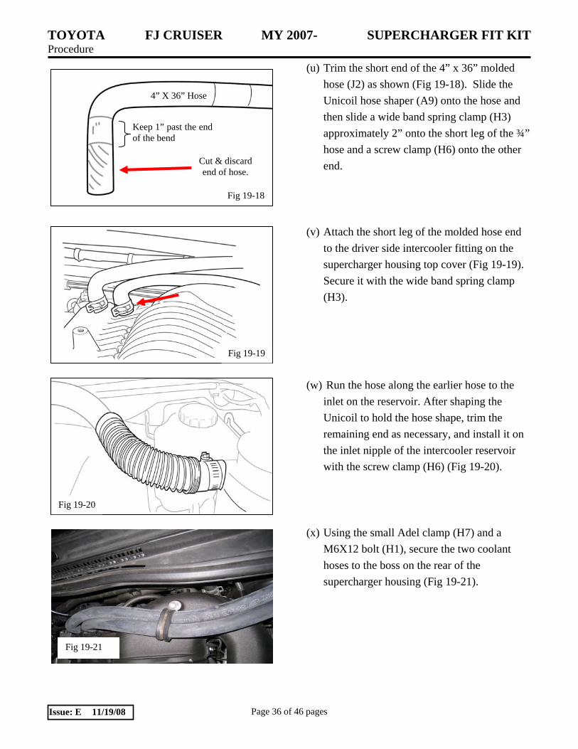
(u) Trim the short end of the 4” x 36” molded hose (J2) as shown (Fig 19-18). Slide the Unicoil hose shaper (A9) onto the hose and then slide a wide band spring clamp (H3) approximately 2” onto the short leg of the ¾” hose and a screw clamp (H6) onto the other end.
(v) Attach the short leg of the molded hose end to the driver side intercooler fitting on the supercharger housing top cover (Fig 19-19). Secure it with the wide band spring clamp (H3).
(w) Run the hose along the earlier hose to the inlet on the reservoir. After shaping the Unicoil to hold the hose shape, trim the remaining end as necessary, and install it on the inlet nipple of the intercooler reservoir with the screw clamp (H6) (Fig 19-20).
(x) Using the small Adel clamp (H7) and a M6X12 bolt (H1), secure the two coolant hoses to the boss on the rear of the supercharger housing (Fig 19-21).

TOYOTA FJ CRUISER MY 2007- SUPERCHARGER FIT KIT Procedure
Page 37 of 46 pages Issue: E 11/19/08
Fig 20-2
Fig 19-22
(y) Finally, place the 6” length of split wire loom over the Unicoil to keep it from scratching the paint (Fig 19-22)
20. Installation of the Intercooler Pump Relay Harness.
(a) Using the supplied M6x20 bolt (H8) preassemble the intercooler relay to the Fuse housing as shown. (Fig 20-1)
(b) Remove the bolt retaining the vehicle ground wire to the fender, take the ground wire from the intercooler pump relay and install it over the vehicle ground wire and reinstall the bolt (Fig 20-2).
(c) Route the two wire connector (red and black wires) through the opening in the radiator support bulkhead (Fig 20-3).
Fig 20-3
Fig 20-1

TOYOTA FJ CRUISER MY 2007- SUPERCHARGER FIT KIT Procedure
Page 38 of 46 pages Issue: E 11/19/08
Fig 20-4
Fig 20-7
(d) Plug the two wire connector into the intercooler pump (Fig 20-4). Secure the extra wire with tie-wraps (H4).
(e) Route the wire harness containing the 10 gauge red wire and the yellow wire along the front of the fuse panel from the fender to the inside of the fuse box (Fig 20-5). Note: the battery is removed for clarity in the figure. Feed both wires up into the fuse box through the same opening used by the vehicle wiring harness.
(f) Remove the nut that is on the B (+) connection in the fuse panel (Fig 20-6) and connect red wire with the 6mm ring terminal from the intercooler relay to the B (+) terminal in the fuse panel (Fig 20-6).
(g) Remove the 10-amp mini fuse labeled EFI No. 2 (Fig 20-7).
Fig 20-6
Fig 20-5

TOYOTA FJ CRUISER MY 2007- SUPERCHARGER FIT KIT Procedure
Page 39 of 46 pages Issue: E 11/19/08
(h) Install the T-tap on the original 10 amp mini fuse (Fig 20-8).
(i) Install the fuse with the T-tap back in the same EFI location and then attach the yellow wire to the T-tap (Fig 20-9). CAUTION: When installing the fuse, make sure the tap is toward the driver side of the vehicle (Fig 20-9).
(j) Install the 15 amp mini fuse (H11) in the intercooler relay fuse holder (Fig 20-10).
(k) Mount the relay/ fuse assembly. (Fig 20-11)
Torque: 8.0 Nm (71 in lbf)
Fig 20-8
Fig 20-9
Tap goes toward driver side of fuse
Fig 20-11
Fig 20-10
Fuse – 15 Amp

TOYOTA FJ CRUISER MY 2007- SUPERCHARGER FIT KIT Procedure
Page 40 of 46 pages Issue: E 11/19/08
Fig 22-4
Fig 22-1
21. Reinstall the Bumper and Radiator Grille.
(Refer to Step 17 for illustrations)
(a) Engage the 2 claws and install the front bumper cover. (17-5)
(b) Tighten the 8 screws and 4 bolts. (17-4) Screw Torque: 3.0 Nm (27 in lbf) Bolt Torque: 8.0 Nm (71 in lbf)
(c) Install the 5 bumper clips (17-3). Remove the protective tape (17-2).
(d) Engage the 5 clips and install the radiator grill. Tighten the 2 grill screws (17-1).
Torque: 3.0 Nm (27 in lbf)
(e) Install the 2 clips on the ends of the grill (17-1).
22. Installation of the Vacuum Hoses.
(a) Remove the cap shown in (Fig 22-1) from the previously removed air surge tank and install it on the forward 3/8”nipple on the supercharger housing (Fig 22-2).
(b) Connect open end B of the EVAP hose (Fig 13-6) to the remaining 3/8” nipple on the supercharger housing (Fig 22-2).
(c) Finally, connect the ventilation hose that was disconnected in step 4 (b) Fig 4-3 to the 3/8” nipple that is on the bottom of housing supercharger housing (Fig 22-4).
Fig 22-2
Vacuum Cap
Purge Hose

TOYOTA FJ CRUISER MY 2007- SUPERCHARGER FIT KIT Procedure
Page 41 of 46 pages Issue: E 11/19/08
Fig 23-1
Fig 23-2
Fig 23-3
Fig 23-4
23. Installation of the Air Cleaner Assembly.
(a) Using a M6x16 bolt (F6), install the air box bracket (F2) to the passenger side cylinder head cover (Fig 23-1) finger tight.
(b) Install the air cleaner assembly using the original bolt and a M6 nut (F4) from the kit (Fig 23-2). Use the other OE air cleaner bolt to secure the air cleaner to the supercharger. Tighten the 3 bolts. Torque: 8.0Nm (71 in lbf).
(c) Reconnect the No. 2 ventilation hose, the vacuum hose, mass air flow meter connector, the throttle motor connector, and the air inlet duct (Fig 23-3).
(d) Reconnect the 2 wire harness clamps removed in step 2 (c) (Fig 23-4).
TOYOTA FJ CRUISER MY 2007- SUPERCHARGER FIT KIT Procedure
Page 42 of 46 pages Issue: E 11/19/08
24. Preparation for Vehicle Start-up.
(a) Using the saved coolant from step 7 (b) pour coolant into the radiator until it is full. Hints:
*Use of improper coolant may damage the engine cooling system.
*Use Toyota Super Long Life Coolant or similar high quality ethylene glycol based non-silicate, non-amine, non-nitrate, and non-borate coolant with long-life hybrid organic acid technology.
*New Toyota vehicles are filled with Toyota Super Long Life Coolant (color is pink, premixed ethylene glycol concentration is approximately 50% and freezing temperature is -35°C (-31°F). When replacing and or adding coolant, Toyota Super Long Life Coolant is recommended.
NOTICE: Do not substitute plain water for engine coolant.
(b) Check the coolant level inside the radiator by squeezing the inlet and outlet radiator hoses several times by hand. If the coolant level goes down, add coolant.
(c) Install the radiator cap.
(d) Slowly pour coolant into the radiator reservoir until it reaches the FULL line.
(e) Fill the intercooler reservoir with the same coolant as the vehicle radiator.
(f) Reinstall and connect the battery.
(g) Once the reservoir is full and will not take any more coolant, turn the ignition key to on, but do not start the engine. This will cause the intercooler pump to run and purge air from the intercooler system. Continue to add coolant to the reservoir until it is full.
TOYOTA FJ CRUISER MY 2007- SUPERCHARGER FIT KIT Procedure
Page 43 of 46 pages Issue: E 11/19/08
Fig 24-1
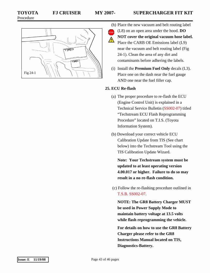
(h) Place the new vacuum and belt routing label (L8) on an open area under the hood. DO NOT cover the original vacuum hose label. Place the CARB OE Emissions label (L9) near the vacuum and belt routing label (Fig 24-1). Clean the area of any dirt and contaminants before adhering the labels.
(i) Install the Premium Fuel Only decals (L3). Place one on the dash near the fuel gauge AND one near the fuel filler cap.
25. ECU Re-flash
(a) The proper procedure to re-flash the ECU (Engine Control Unit) is explained in a Technical Service Bulletin (SS002-07) titled “Techstream ECU Flash Reprogramming Procedure” located on T.I.S. (Toyota Information System).
(b) Download your correct vehicle ECU Calibration Update from TIS (See chart below) into the Techstream Tool using the TIS Calibration Update Wizard.
Note: Your Techstream system must be updated to at least operating version 4.00.017 or higher. Failure to do so may result in a no re-flash condition.
(c) Follow the re-flashing procedure outlined in T.S.B. SS002-07.
NOTE: The GR8 Battery Charger MUST be used in Power Supply Mode to maintain battery voltage at 13.5 volts while flash reprogramming the vehicle.
For details on how to use the GR8 Battery Charger please refer to the GR8 Instructions Manual located on TIS, Diagnostics-Battery.

TOYOTA FJ CRUISER MY 2007- SUPERCHARGER FIT KIT Procedure
Page 44 of 46 pages Issue: E 11/19/08
NOTE: The vehicle WILL NOT operate properly without this ECU update.
26. Testing and Evaluation.
(a) Start the engine and let it idle.
(b) Check the fuel system for any leaks.
(c) IMPORTANT: Check the serpentine belt drive systems for correct alignment on ALL pulleys.
(d) Check the coolant system for any leaks.
(i) Set the A/C system as follows:
Fan Speed………Any setting except OFF
Temperature…….Toward Warm
A/C Switch……...OFF
(ii) Maintain the engine speed at 2,000 to 2,500 rpm and warm up the engine until the cooling fan operates.
(iii) Squeeze the inlet and outlet radiator hoses several times by hand while warming up the engine.
(e) Check the air intake system to ensure there are no leaks and for tightness.
(f) Stop the engine and wait for the coolant to cool down.
Model Model Year Ta rget Ca libra tion ID Supercha rger Calibration ID
33546000
33546100
200 8 33554000
200 9 33568000
200 7 33545000
33555000
33555100
200 9 33569000
FJ Cru ise r 2W D, 4W D A/T
3YW K0300
3YW K0400200 8
200 7
FJ Cruiser 4WD M/T

TOYOTA FJ CRUISER MY 2007- SUPERCHARGER FIT KIT Procedure
Page 45 of 46 pages Issue: E 11/19/08
(g) Carefully remove the radiator cap and check the coolant level inside the radiator and add coolant if necessary. Reinstall the radiator cap.
(h) Check the coolant level inside the radiator reservoir. If it is below the full level, add coolant.
(i) Check the coolant in the intercooler reservoir and add coolant if necessary.
(j) Drive test the vehicle. If all is okay, park and proceed with the next step. If not, troubleshoot as necessary.
(k) Use the diagnostic Techstream tool to check for ECU error codes.
(l) Place the Supercharger noise Mirror hanger card (L7) on the inside rearview mirror.
(m) Complete and mail the warranty registration card (L6). Note: The installation of the Supercharger is not complete until this card has been returned to TRD.
(n) Place all removed factory hardware, components, and this instruction sheet into the original TRD kit box and give it to the customer and or place it in the vehicle cargo compartment.
(o) IMPORTANT: Review with the customer/end-user that the supercharger will make a slight noise at idle that increases as the throttle is opened and that this is normal.
(p) IMPORTANT: Review with the customer/end-user that it is it is imperative that only 91octant or higher fuel be used after the supercharger is installed. Performance will suffer and engine damage is possible otherwise.
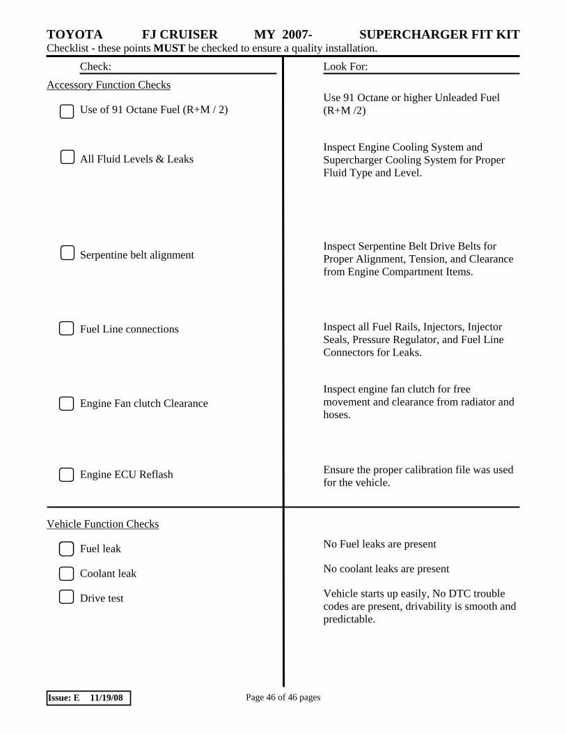
TOYOTA FJ CRUISER MY 2007- SUPERCHARGER FIT KIT Checklist - these points MUST be checked to ensure a quality installation.
Check: Look For:
Page 46 of 46 pages Issue: E 11/19/08
Accessory Function Checks
Use of 91 Octane Fuel (R+M / 2)
All Fluid Levels & Leaks
Serpentine belt alignment
Fuel Line connections
Engine Fan clutch Clearance
Engine ECU Reflash
Vehicle Function Checks
Fuel leak
Coolant leak
Drive test
Use 91 Octane or higher Unleaded Fuel (R+M /2)
Inspect Engine Cooling System and Supercharger Cooling System for Proper Fluid Type and Level.
Inspect Serpentine Belt Drive Belts for Proper Alignment, Tension, and Clearance from Engine Compartment Items.
Inspect all Fuel Rails, Injectors, Injector Seals, Pressure Regulator, and Fuel Line Connectors for Leaks.
Inspect engine fan clutch for free movement and clearance from radiator and hoses.
Ensure the proper calibration file was used for the vehicle.
No Fuel leaks are present
No coolant leaks are present
Vehicle starts up easily, No DTC trouble codes are present, drivability is smooth and predictable.


![FJ CRUISER - Auto-Brochures.com Cruiser/Toyota_US FJCruiz… · Stability Control (VSC) [1] + Traction Control ... Multi-information display floating ball type ... FJ Cruiser 4x2](https://static.fdocuments.in/doc/165x107/5ad0339b7f8b9a71028d9a34/fj-cruiser-auto-cruisertoyotaus-fjcruizstability-control-vsc-1-traction.jpg)


![FJ CRUISER - Auto-Brochures.com...Oct 23, 2009 · Model Overview FJ Cruiser shown in Iceberg with available Upgrade Package #2. [6] FJ Cruiser 4WD shown in Dark Charcoal with available](https://static.fdocuments.in/doc/165x107/60bb53cc636dbe2deb04a06b/fj-cruiser-auto-oct-23-2009-model-overview-fj-cruiser-shown-in-iceberg.jpg)