
Tower for PWM Control - SureFire Ag · 2018-08-21 · 396-001060 SureFire Tower for JD GRC GS2 &...
60
396-001060 SureFire Tower for JD GS2 & GS3-PWM Control Revised 08/21/2018 Tower Electric Pump Fertilizer System for John Deere GRC GS2 2600 & GS3 2630 Maximum Application Rates in GPA on 30" Rows at 6 MPH (no agitation) Rows 8 12 16 24 Max GPA 20 12 9 5 396-001060 Maximum Application Rates with Two 5.3 GPM Electric Pumps & Tower for PWM Control
Transcript of Tower for PWM Control - SureFire Ag · 2018-08-21 · 396-001060 SureFire Tower for JD GRC GS2 &...

396-001060 SureFire Tower for JD GS2 & GS3-PWM Control Revised 08/21/2018
Tower Electric Pump Fertilizer System
for John Deere GRC GS2 2600 & GS3 2630
Maximum Application Rates in GPA on 30" Rows at 6 MPH (no agitation)
Rows 8 12 16 24
Max GPA 20 12 9 5
396-001060
Maximum Application Rates with Two 5.3 GPM Electric Pumps
& Tower for PWM Control

396-001060 SureFire Tower for JD GRC GS2 & GS3-PWM Control Revised 08/21/2018
SureFire
Ag Sys
tems
396-001060 SureFire Tower for JD GRC GS2 & GS3-PWM Control Revised 08/21/2018
Table Of Contents
A Introduction
Introduction • Basic Steps to Install your Fertilizer System ........................................... 2 • Complete Fertilizer System Example Drawings ...................................... 3-4
B Components
Liquid
Components - Liquid • Flowmeters, Section Valves .................................................................... 5-6 • Pressure Sensor, Pump Priming and Air Bleed Valve ............................ 7 • Flow Indicators and Manifolds, Check Valves, Orifice Charts ................. 8-15 • Dual Check Valve Systems, Row Distribution ......................................... 16-19
D Components
Wiring & Elec.
Components - Wiring & Electrical • Connecting to John Deere Rate Controller ............................................. 20 • Schematics, System Layout, PWM EPD ................................................. 21-22• Harness Drawings ................................................................................... 24-31
E Installation Overview
Installation Overview • Floating Ball Flow Indicators, Tower Mounting Options .......................... 32-34 • Tower 110 Plumbing Overview and Valve Operation, Recirculation ....... 35 • Tower 200 Plumbing Overview and Valve Operation, Agitation .............. 36-37
F Setup &
Operation
Setup & Operation • John Deere Rate Controller Setup .......................................................... 39 • Implement Setup ..................................................................................... 40 • System Setup, PWM Setup, Pressure Sensor Calibration ...................... 41-42 • Set up Alarms and Rates ........................................................................ 43 • Initial Operation, Section Test ................................................................. 44• Nozzle Flow Check ................................................................................. 45• Calibrate Flowmeter ................................................................................ 46
H Maintenance
& Parts
Maintenance & Parts• Winterization ........................................................................................... 54 • Pre-season Service ............................................................................... 54
G Trouble- Shooting
Troubleshooting • Pump Will Not Run, Section Valve Won’t Move ...................................... 47-48 • Application Rate Fluctuates, Slow Getting to Target Rate ..................... 49 • Flowmeter Tap Test, Diagnostics-Readings Screens ............................. 50 • Charts to determine system flow requirements ....................................... 51-53
©2010-2018 SureFire Ag Systems
Appendix• IMPORTANT—Helpful Troubleshooting Information ............................... 55-56
QuickStart Setup Instructions . . . . . . . . . . . . . . . . . . . . . . . . . . . . . . 57-58
SureFire
Ag Sys
tems

396-001060 SureFire Tower for JD GRC GS2 & GS3-PWM Control 2 Revised 08/21/2018
General Description
You have purchased a SureFire fertilizer system for your equipment. This system will be controlled by your John Deere GS2 or GS3 display and John Deere Rate Controller, which you will need to purchase from your John Deere dealer. The GS2 2600 and GS3 2630 function almost identically in regards to rate control. The Rate Controller will adjust the speed of the SureFire electric pumps based on feedback from the flowmeter and vehicle speed. The system is capable of using John Deere Section Control to minimize overlap areas with optional section valves.
A Introduction
Basic Installation Steps
1. Have John Deere GreenStar Rate Controller (GRC) mounted and wired by your John DeereDealer to connect to your GS2 or GS3 display in the cab.
2. Open the packages and familiarize yourself with the components. See the System OverviewExamples on the following pages to see the big picture of how SureFire Fertilizer Systems areinstalled. Refer to manual sections B & D for component information.
3. Mount the Tower or Accelerator Tank on your equipment. Electric pumps should be located closeto the tanks. They will push the product a long distance, but are not as good at pulling product along distance.
4. Plumb the tank to the Tower inlet. See section E for details.
5. Install the plumbing kit including section valves, flow indicator columns / manifolds, check valves,plumbing to each row unit delivery point. See section B for information on these components.
6. Attach the flowmeter outlet to section valve or manifold inlet. Attach section valve outlets to flowindicator inlets.
7. Attach harnesses as shown in Section D.
8. Set up Controller for SureFire fertilizer system as shown in Section F.
9. Fill system with water, conduct initial operation and tests per Section F.
10. Winterize system with RV Antifreeze if freezing temperatures are expected.
11. Do pre-season service each year as described on page 49.Sure
Fire Ag S
ystem
s

396-001060 SureFire Tower for JD GRC GS2 & GS3-PWM Control 3 Revised 08/21/2018
System Overview - Example 1The following gives an example of a complete SureFire Fertilizer system with these compo-nents: • John Deere GS2 or GS3• John Deere GreenStar Rate Controller (GRC)• Tower 110• Section Valves• Flow Indicators• Check Valves with Colored Disc Orifices
A Introduction
Fertilizer Opener, Seed Firmer, SS Tube, etc.
Typically 3/4” hose used to feed each manifold. Length of this hose can vary significantly.
This is usually 1/4” or 3/8” tub-ing or 3/8” hose. Typical length is 1-4’ with check valves placed on each row that dis-tance from ground.
This is usually 1/4” or 3/8” tubing or 3/8” hose. Maxi-mum recommend-ed length is 20 feet and lengths do not need to be equal.
Check valve is mounted near each row. 1/4” turn cap is always check valve outlet. Colored disc orifice can be placed under cap.
TANK
Typically 3/4” hose used from the flowmeter outlet to section valves. If not using section valves, flowmeter is plumbed directly to flow indicators or a simple tee is used to divide flow to multiple flow indicator manifolds.
Tractor Battery 12 Volt
EPD Power Cable
SureFire 37 Pin to 12-pin Product and 14-pin Section Adapter Harness- (connector detail in Section D) (Older harnesses have twin 16-pin connectors)
14-pin Section Valve Harness(connector detail in Section D)
12-pin PWM Pump Harness(connector detail in Section D)
John Deere Rate Controller
GS2 or GS3 in cab
John Deere Harnesses
SureFire
Ag Sys
tems

396-001060 SureFire Tower for JD GRC GS2 & GS3-PWM Control 4 Revised 08/21/2018
System Overview - Example 2The following gives an example of a complete SureFire Fertilizer system with these components: • John Deere GS2 or GS3• John Deere GreenStar Rate Controller (GRC)• Accelerator with Tower 200• Dual Check Valve Distribution System• Dual Metering Tube
A Introduction
Fertilizer Opener, Seed Firmer, SS Tube, etc.
Typically 1/2” or 3/4” hose used to feed dual check valve distribution system.
Tractor Battery 12 Volt
EPD Power Cable
Dual Check Valve
Dual Check Valve Mounting Bracket
SureFire 37 Pin to 12-pin Prod-uct and 14-pin Section Adapter Harness- (connector detail in Section D) (Older harnesses have twin 16-pin connectors)
12-pin PWM Pump Harness(connector detail in Section D)
John Deere Rate Controller
GS2 or GS3 in cab
John Deere Harnesses
14-pin Connector to SectionValve Harness, not used in thislayout with no section valves.
SureFire
Ag Sys
tems
396-001060 SureFire Tower for JD GRC GS2 & GS3-PWM Control 5 Revised 08/21/2018
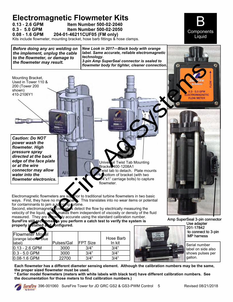
Electromagnetic Flowmeter Kits 0.13 - 2.6 GPM Item Number 500-02-2040 0.3 - 5.0 GPM Item Number 500-02-2050 0.08 - 1.6 GPM 204-01-46211CUF05 (FM only)Kits include flowmeter, mounting bracket, hose barb fittings & hose clamps.
Flowmeter Model (orange label or blue label) Pulses/Gal FPT Size
Hose Barb In kit
0.13 - 2.6 GPM 3000 3/4” 3/4”
0.3 - 5.0 GPM 3000 3/4” 3/4”
0.08-1.6 GPM 22700 3/4” 3/4”
B Components
Liquid
Mounting Bracket, Used in Tower 110 & 200 (Tower 200 shown) 410-2106Y1
Before doing any arc welding on the implement, unplug the cable to the flowmeter, or damage to the flowmeter may result.
Universal Twist Tab Mounting Bracket 400-1208A1 Twist tab to detach. Plate mounts to bottom of bracket (with two 1/4”x1” carriage bolts) to capture flowmeter.
Electromagnetic flowmeters are superior to traditional turbine flowmeters in two basic ways. First, they have no moving parts. This translates into no wear items or potential for contaminants to jam a spinning turbine. Second, electromagnetic flowmeters detect the flow by electrically measuring the velocity of the liquid, which makes them independent of viscosity or density of the fluid measured. They are extremely accurate using the standard calibration number. SureFire still recommends you perform a catch test to verify the system is properly installed and configured.
Each flowmeter has a different diameter sensing element. Although the calibration numbers may be the same, the proper sized flowmeter must be used. * Earlier model flowmeters (meters with white labels with black text) have different calibration numbers. Seethe documentation for those meters to find calibration numbers.)
Caution: Do NOT power wash the flowmeter. High pressure spray directed at the back edge of the face plate or at the wire connector may allow water into the flowmeter electronics.
New Look in 2017—Black body with orange label. Same accurate, reliable electromagnetic technology. 3-pin Amp SuperSeal connector is sealed toflowmeter body for tighter, cleaner connection.
Amp SuperSeal 3-pin connector Use adapter
201-17842to connect to 3-pinMP harness
Serial number label on side also shows pulses per gallon.
Amp SuperSeal 3-pin connector Use adapter
201-17842to connect to 3-pinMP harnessSure
Fire Ag S
ystem
s

396-001060 SureFire Tower for JD GRC GS2 & GS3-PWM Control 6 Revised 08/21/2018
Section Valves
Liquid inlet
105-100075BRB90
105-100PLG (alternate105-100PLG025 includes 1/4” pipe
thread for gauge)
103-2501Y1(single complete valve)
117-211-0066Liquid outlet to each section
Additional Parts: 1” Gasket 105-100G-H1” Clamp 105-FC100
How it Works
Section valves can be assembled into groups with a common inlet to control flow to each section. Common assemblies use up to 5-6 valves, however, more can be used where practical. Many alternate fittings can be used to accommodate different hose sizes and configurations.
The valves have a 3-pin weather pack electrical connector. This has a power, ground, and switched signal wire. The power measured to ground should have 12 volts when the controller is on. The switched signal wire will have 12 volts to turn the valve on, and 0 volts to turn the valve off.
Wiring Connector: Pin A—Red, 12 Volts + Pin B—Black, Ground - Pin C—White, Signal
12V=on ; 0V=off
Mounting Hardware: 2 Valve Bolt Kit 384-1100Mounting Bracket 400-2493Y1
B Components
Liquid
The Tower 110 can have up to 6
section valves mounted directly to the
top of it with this bracket.
Tower 110 Section Valve Bracket Item Number 410-2110Y2
Note: Ensure back-side port
is capped prior to use
SureFire
Ag Sys
tems

396-001060 SureFire Tower for JD GRC GS2 & GS3-PWM Control 7 Revised 08/21/2018
The Tower 110 and 200 come equipped with a 100 psi pressure sensor to work with the John Deere controller. This sensor is a 3 wire type sensor for compatibility with John Deere. The sensor has a 1/4” MPT fitting.
The John Deere Rate Controller is able to accommodate 2 pressure sensors, both of which can be displayed on the GS3 display. (When using adapter harness 213-00-3765Y1, if the sensor is plugged into the Section harness, it must be set up as Sensor 2.)
The John Deere display will show the system pressure on the in cab screen. The pressure reading is only for informational purposes and is NOT used in the flow control process. Flow control uses the flowmeter feedback only.
The pressure sensor is very helpful to optimize system performance and trouble shoot any issues.
The pressure transducer is factory calibrated and will display a very accurate pressure reading on the Deere display. No manual gauge is required. Unplug the sensor when entering the Calibration number.)
Pressure Sensor B Components
Liquid
Pressure Sensor (3 wire type) with harness 521-05-050150
Pump Priming and Air Bleed Valve An air bleed valve is included with each pump to aid in system priming. It is shipped in the pump accessories bag and must be installed during system installation.
Why use an air bleed valve: Most fertilizer systems are equipped with a 4 lb. or 10 lb. check valve on the end of each hose delivering fertilizer to the ground. These valves do not let air escape from the system, unless it is pressurized. 12 volt liquid pumps are not good air compressors. Therefore, the pump can struggle to prime due to air trapped on the outlet side of the pump.
The air bleed valve is a small 1/4” valve that when opened lets air escape from the pump outlet at zero pressure. Open until liquid comes out and then close the valve.
How to install the air bleed valve: Remove the 1/4” plug from the quick connect fitting on the center cross on the Tower (see picture). Next, insert the 1/4” tubing in the quick connect fitting. Run the 1/4” tubing to an easily accessible spot on your equipment. Next, cut the tubing and push the 1/4” valve onto the tubing. Finally, run the tubing to a low location where any fertilizer that escapes will run on the ground. Be sure the air bleed valve tube does not become plugged with dirt or it will not allow the air to bleed.
1/4” Tubing 1/4” air bleed valve
GS2 / GS3 Pressure Calibration: 50 mv/psi
Shipped from factory with plug installed. Sure
Fire Ag S
ystem
s

396-001060 SureFire Tower for JD GRC GS2 & GS3-PWM Control 8 Revised 08/21/2018
B Components
Liquid
Floating Ball Flow Indicator & Manifold System
Flow indicators give a clear visual signal that a fertilizer system is working. These indicators use an o-ring and wire clip connection to snap together in any configuration necessary.
SureFire has simple tee brackets and U-bolts that will mount these to a variety of bar sizes.
Two main types of flow indicators are used. On 30” row spacing, the low flow column with 1/4” or 3/8” push to connect outlet is recommended for rates under 10 GPA. For rates over 10 GPA the full flow column with 3/8” hose barb outlet is preferred.
Parts List
Complete Columns 701-20460-95 Single Full Flow Column with 3/8" HB - 90 Degree Outlet 701-20460-96 Single Full Flow Column with 1/4" FPT - 90 Degree Outlet
701-20460-97 Single Low Flow Column with 1/4" QC - 90 Degree Outlet 701-20460-98 Single Full Flow Column with 3/8” QC - 90 Degree Outlet 701-20460-99 Single Full Flow Column with 1/2” HB - 90 Degree Outlet
Fittings 701-20503-00 ORS x 3/4" HB - Straight Service Parts Only 701-20511-00 ORS x 3/8" HB - 90 Degree 701-20460-00 Full Flow Column 701-20512-00 ORS x 1/2" HB - 90 Degree 701-20470-00 Low Flow Column 701-20513-00 ORS x 3/4" HB - 90 Degree 701-20460-04 Wilger Lock U-clip 701-20516-00 ORS x 1/4" QC - 90 Degree 701-20460-05 Flow Indicator Ball - 1/2" SS Ball
701-20517-00 ORS x 3/8" QC - 90 Degree 701-20460-06 Flow Indicator Ball - Maroon Glass
701-20518-00 ORS x 1/4" FPT - 90 Degree 701-20460-07 Flow Indicator Ball - Red Celcon 701-20519-00 ORS x 1/4" FPT - Straight 701-20460-08 Flow Indicator Ball - Green Poly 701-20520-00 ORS Male x ORS Female - 90 degree 701-20460-09 Flow Indicator Ball - Black Poly
701-20521-00 Wilger End Cap 701-20460-15 Viton O-Ring for column & fit-tings
701-20523-00 ORS Male x ORS Female x 3/8" FPT - Isolator 701-40225-05 Viton O-Ring for Orifice 701-20525-00 ORS Male x ORS Male x 1" FPT - Tee
Brackets & U-Bolts
400-1037A1 3-6 Row Bracket
400-1036A2 7-12 Row Bracket
400-2011A1 White Backer Plate for 3-6 Row Bracket
400-2010A1 White Backer Plate for 7-12 Row Bracket
400-1315A2 Flow Indicator Bracket, 6-8 in wide hitch mount
Product DistributionTo assure proper and even distribution to each row, the product being applied must be metered to each individual row. This metering is done by one of the 3 following methods which create back pressure so an equal amount of liquid is applied to each row. 1. A metering orifice may be placed in the top cap of each floating ball flow indicator. (See
photos on page 10—this is not used very often.)2. A metering orifice may be placed in the check valve cap in the line that leads to each
row. (See photo on page 12)3. A dual metering tube kit with dual check valves may be used. (See pages 16-19)
SureFire
Ag Sys
tems

396-001060 SureFire Tower for JD GRC GS2 & GS3-PWM Control 9 Revised 08/21/2018
701-20521-00End Cap
400-1036A27-12 RowBracket
101-100075BRB1” MPT x 3/4” HB
The full flow column is typically used with rates over 10 GPA on 30” rows. For rates less than 10 GPA SureFire recommends the low flow columns with 1/4” or 3/8” push to connect outlet fittings.
The full flow columns are most often assembled with 3/8” hose barb outlets. See the low flow info below for the difference between full and low flow columns.
701-20460-95Full Flow Columnw/ 3/8” HB Outlet
701-20525-00Center Fed Teewith Gauge Port
380-1001Fits 7”x7” Tube
Full Flow Indicators w/ 3/8” Hose Barb Outlet Column Flow (GPM): .05-2.70 GPM Equivalent Application Rate On 30” Rows at 6 MPH: 2-70 GPA
Ball Selection for 30” Rows GPM GPA Ball .05-.18 2-6 Green Plastic* .09-.30 3-10 Red Plastic* .31-.72 10-20 Maroon Glass .40-2.1 13-70 Stainless Steel (1/2”)
*Plastic balls may float on heavier fertilizers, such as 10-34-0.SureFire recommends using the low flow column for theseflow rates.
1/4” x 2” Bolt
Floating Ball Flow Indicators- Full Flow Column (mostly 3/8” HB) B
Components Liquid
400-2010A112 Row WhiteVisibility BackerPlate
400-1037A13-6 RowBracket
400-2011A16 Row White Visi-bility Backer Plate
701-20513-00 3/4” HB90 degreeinlet
Low Flow Column (mostly 1/4” QC) The low flow column has a smaller internal diameter. This means a
heavier ball can be used to monitor a smaller flow. SureFire uses the low flow columns with 1/4” push to connect out-
let fittings. The flow capability of 1/4” tubing and the low flow column are a great pair for rates on 30” rows under 10 GPA.
Externally, the low flow column can only be identified by “Low Flow” molded into one side of the column. All the same fittings work with low flow and full flow columns.
Low Flow Indicators w/ 1/4” Push to Connect Outlet Column Flow (GPM): .03-.30 GPM *** Low Flow Column with 3/8” hose barb .03 - .70 GPM
Equivalent Application Rate On 30” Rows at 6 MPH (1/4” QC): 1-10 GPA
Ball Selection for 30” Rows GPM GPA Ball .03-.09 1-3 Green Plastic* .05-.14 2-4 Red Plastic* .10-.18 3-6 Maroon Glass .15-.70 5-10 Stainless Steel (1/2”)
*These balls may float on heavier fertilizers, such as 10-34-0. Use MaroonGlass in this case.
SureFire
Ag Sys
tems

396-001060 SureFire Tower for JD GRC GS2 & GS3-PWM Control 10 Revised 08/21/2018
Floating Ball Flow Indicators– Metering Orifice Selection for 30” Rows See www.surefireag.com for other row spacings (This system is not used very often)
Remove top fitting of each column. Then push metering orifice into bottom of each outlet fitting. (This is not used very often.)
Orifice PSI 4.0 4.5 5.0 5.5 6.0 6.5 7.0
10 0.043 2.15 1.91 1.72 1.56 1.43 1.32 1.23
20 0.061 3.02 2.69 2.42 2.20 2.02 1.86 1.73
30 0.075 3.72 3.31 2.98 2.71 2.48 2.29 2.13
40 0.087 4.29 3.82 3.43 3.12 2.86 2.64 2.45
50 0.097 4.82 4.28 3.85 3.50 3.21 2.97 2.75
60 0.106 5.26 4.67 4.21 3.82 3.50 3.23 3.00
10 0.070 3.46 3.08 2.77 2.52 2.31 2.13 1.98
20 0.098 4.86 4.32 3.89 3.54 3.24 2.99 2.78
30 0.120 5.96 5.30 4.77 4.33 3.97 3.67 3.40
40 0.139 6.88 6.11 5.50 5.00 4.58 4.23 3.93
50 0.156 7.71 6.85 6.17 5.61 5.14 4.74 4.41
60 0.170 8.41 7.48 6.73 6.12 5.61 5.18 4.81
10 0.090 4.47 3.97 3.57 3.25 2.98 2.75 2.55
20 0.127 6.31 5.61 5.05 4.59 4.21 3.88 3.60
30 0.157 7.75 6.89 6.20 5.64 5.17 4.77 4.43
40 0.181 8.94 7.94 7.15 6.50 5.96 5.50 5.11
50 0.202 9.99 8.88 7.99 7.26 6.66 6.15 5.71
60 0.221 10.95 9.73 8.76 7.96 7.30 6.74 6.26
10 0.119 5.91 5.26 4.73 4.30 3.94 3.64 3.38
20 0.169 8.37 7.44 6.69 6.08 5.58 5.15 4.78
30 0.207 10.25 9.11 8.20 7.45 6.83 6.31 5.86
40 0.239 11.83 10.51 9.46 8.60 7.88 7.28 6.76
50 0.267 13.23 11.76 10.58 9.62 8.82 8.14 7.56
60 0.293 14.50 12.89 11.60 10.55 9.67 8.92 8.29
10 0.149 7.36 6.54 5.89 5.35 4.91 4.53 4.21
20 0.210 10.38 9.23 8.31 7.55 6.92 6.39 5.93
30 0.257 12.70 11.29 10.16 9.24 8.47 7.82 7.26
40 0.296 14.67 13.04 11.74 10.67 9.78 9.03 8.39
50 0.332 16.43 14.60 13.14 11.95 10.95 10.11 9.39
60 0.363 17.96 15.96 14.37 13.06 11.97 11.05 10.26
10 0.218 10.78 9.58 8.62 7.84 7.18 6.63 6.16
20 0.307 15.20 13.51 12.16 11.05 10.13 9.35 8.69
30 0.376 18.62 16.55 14.89 13.54 12.41 11.46 10.64
40 0.435 21.51 19.12 17.21 15.64 14.34 13.24 12.29
50 0.486 24.05 21.38 19.24 17.49 16.03 14.80 13.74
60 0.532 26.33 23.40 21.06 19.15 17.55 16.20 15.04
10 0.341 16.87 14.99 13.49 12.27 11.24 10.38 9.64
20 0.481 23.83 21.18 19.06 17.33 15.89 14.66 13.62
30 0.590 29.22 25.97 23.37 21.25 19.48 17.98 16.70
40 0.681 33.73 29.98 26.98 24.53 22.49 20.76 19.27
50 0.762 37.72 33.53 30.17 27.43 25.14 23.21 21.55
60 0.835 41.31 36.72 33.05 30.04 27.54 25.42 23.60
10 0.553 27.38 24.34 21.90 19.91 18.25 16.85 15.64
20 0.782 38.72 34.42 30.98 28.16 25.82 23.83 22.13
30 0.956 47.31 42.05 37.85 34.41 31.54 29.11 27.03
40 1.106 54.76 48.67 43.81 39.82 36.50 33.70 31.29
50 1.239 61.33 54.51 49.06 44.60 40.88 37.74 35.04
60 1.354 67.02 59.58 53.62 48.74 44.68 41.24 38.30
10 0.649 32.11 28.54 25.69 23.35 21.41 19.76 18.35
20 0.920 45.56 40.50 36.45 33.13 30.37 28.04 26.03
30 1.124 55.63 49.45 44.51 40.46 37.09 34.24 31.79
40 1.301 64.39 57.24 51.52 46.83 42.93 39.63 36.80
50 1.451 71.84 63.86 57.47 52.25 47.89 44.21 41.05
60 1.584 78.41 69.70 62.73 57.03 52.27 48.25 44.81
10 0.938 46.43 41.27 37.15 33.77 30.96 28.57 26.53
20 1.319 65.27 58.02 52.22 47.47 43.51 40.17 37.30
30 1.619 80.16 71.26 64.13 58.30 53.44 49.33 45.81
40 1.867 92.43 82.16 73.94 67.22 61.62 56.88 52.82
50 2.088 103.38 91.89 82.70 75.19 68.92 63.62 59.07
60 2.292 113.46 100.85 90.76 82.51 75.64 69.82 64.83
All application rates (gallons/acres) are estimates based on 0-28-0 (10.65 lbs/gallon) at 70 degrees F.
130
MPH
28
35
40
46
52
63
78
98
Gal/Min
28-0-0
107
Tower Electric Pump Pressure Recommendations (with 4 lb check valves): • Minimum 10 PSI• Maximum 30 PSI (pump can do 50
PSI or more if total output is not toogreat)
PumpRight Hydraulic Pressure Recommendations (with 10 lb check valves): • Minimum 20 PSI• Maximum 80 PSI
Chart is for 28-0-0 Fertilizer @ 70° • Heavier fertilizers (like 10-34-0) will
have 5-15% less flow than chartindicates for a certain pressure
• Cold fertilizers will cause systempressure to increase at a givenapplication rate.
• Tower Electric Pump Systems willhave reduced flow and increasedelectrical current draw due to coldfertilizer increasing operatingpressure. Use the largest orificepossible for cold weatheroperation.
B Components
Liquid
30” Spacing
If using a metering orifice in the flow indicator, the orifice replaces the ball retainer. If not using an orifice here, the ball retainer must be in place.
Ball retainer
or
Orifice
SureFire
Ag Sys
tems

396-001060 SureFire Tower for JD GRC GS2 & GS3-PWM Control 11 Revised 08/21/2018
The recommended check valve for most PumpRight installations is the 10 lb check with 3/8” hose barbs. This works with 3/8” rubber hose which SureFire recommends for most applications over 10 GPA on 30” rows. The recommended minimum system operating pressure for this check is 20 psi, to ensure all checks open fully.
Check Valves
Complete Assembly PN 136-10-06HB06HB
101-025038-H 133-03-40501-00Black Cap = 10 PSI
Disc Orifice (optional)
133-03-40160Gasket
Inlet
Outlet—RadialLock Cap
4 lb check valves are typically used with electric pump systems. SureFire recommends this valve for use with 1/4” tubing applying up to 10 GPA on 30” rows. The recommended minimum system operating pressure for this check is 10 psi, to ensure all checks open fully.
133-03-40502-P4Blue Cap = 4 PSI
Disc Orifice (optional)
133-03-40160Gasket
Inlet
Outlet—RadialLock Cap
4 lb check valve with 1/4” quick connect fittings
Assembly Part Number Description Suggested Uses (30” rows)
136-10-04QC04QC 1/4" QC x 1/4" QC 10 lb < 10 GPA with PumpRight & 1/4” Tubing
136-10-06QC06QC 3/8" QC x 3/8" QC 10 lb With 3/8” tubing plumbing
136-04-06HB06HB 3/8" HB x 3/8" HB 4 lb > 10 GPA with Electric Pumps
136-04-08HB08HB 1/2" HB x 1/2" HB 4 lb > 50 GPA with PumpRight
136-10-08HB08HB 1/2" HB x 1/2" HB 10 lb > 50 GPA with PumpRight
Special Purpose Check Valve Assemblies
132-40435-05
Complete Assembly PN 136-04-04QC04QC
10 lb check valve with 3/8” hose barbs B
Components Liquid
132-40424-05
FLOW
FLOW
SureFire
Ag Sys
tems

396-001060 SureFire Tower for JD GRC GS2 & GS3-PWM Control 12 Revised 08/21/2018
Colored Disc Orifice Chart for 30” rows B Components
Liquid
Tower Electric Pump Pressure Recommendations (with 4 lb check valves): • Minimum 10 PSI• Maximum 30 PSI (pump can do 50
PSI or more if total output is not toogreat)
PumpRight Pressure Recommendations (with 10 lb check valves): • Minimum 20 PSI• Maximum 80 PSI
Chart is for 28-0-0 Fertilizer @ 70° • Heavier fertilizers (like 10-34-0) will
have 5-15% less flow than chartindicates for a certain pressure
• Cold fertilizers will cause systempressure to increase at a givenapplication rate.
• Tower Electric Pump Systems willhave reduced flow and increasedelectrical current draw due to coldfertilizer increasing operatingpressure. Use the largest orificepossible for cold weatheroperation. This is absolutelyessential for 24-row systems usingelectric pumps.
PSI 4.0 4.5 5.0 5.5 6.0 6.5 7.0
10 0.033 1.62 1.44 1.30 1.18 1.08 1.00 0.93
20 0.046 2.28 2.02 1.82 1.66 1.52 1.40 1.30
30 0.057 2.80 2.49 2.24 2.04 1.87 1.73 1.60
40 0.065 3.24 2.88 2.59 2.36 2.16 1.99 1.85
50 0.073 3.64 3.23 2.91 2.64 2.42 2.24 2.08
60 0.081 3.99 3.54 3.19 2.90 2.66 2.45 2.28
10 0.050 2.50 2.22 2.00 1.82 1.66 1.54 1.43
20 0.072 3.55 3.15 2.84 2.58 2.37 2.18 2.03
30 0.088 4.34 3.85 3.47 3.15 2.89 2.67 2.48
40 0.101 4.99 4.44 4.00 3.63 3.33 3.07 2.85
50 0.112 5.56 4.95 4.45 4.05 3.71 3.42 3.18
60 0.124 6.13 5.45 4.91 4.46 4.09 3.77 3.50
10 0.070 3.46 3.08 2.77 2.52 2.31 2.13 1.98
20 0.098 4.86 4.32 3.89 3.54 3.24 2.99 2.78
30 0.120 5.96 5.30 4.77 4.33 3.97 3.67 3.40
40 0.139 6.88 6.11 5.50 5.00 4.58 4.23 3.93
50 0.156 7.71 6.85 6.17 5.61 5.14 4.74 4.41
60 0.170 8.41 7.48 6.73 6.12 5.61 5.18 4.81
10 0.094 4.64 4.13 3.71 3.38 3.10 2.86 2.65
20 0.132 6.53 5.80 5.22 4.75 4.35 4.02 3.73
30 0.162 8.02 7.13 6.41 5.83 5.34 4.93 4.58
40 0.187 9.24 8.22 7.39 6.72 6.16 5.69 5.28
50 0.209 10.34 9.19 8.27 7.52 6.89 6.36 5.91
60 0.228 11.30 10.05 9.04 8.22 7.53 6.95 6.46
10 0.119 5.91 5.26 4.73 4.30 3.94 3.64 3.38
20 0.169 8.37 7.44 6.69 6.08 5.58 5.15 4.78
30 0.207 10.25 9.11 8.20 7.45 6.83 6.31 5.86
40 0.239 11.83 10.51 9.46 8.60 7.88 7.28 6.76
50 0.267 13.23 11.76 10.58 9.62 8.82 8.14 7.56
60 0.293 14.50 12.89 11.60 10.55 9.67 8.92 8.29
10 0.149 7.36 6.54 5.89 5.35 4.91 4.53 4.21
20 0.210 10.38 9.23 8.31 7.55 6.92 6.39 5.93
30 0.257 12.70 11.29 10.16 9.24 8.47 7.82 7.26
40 0.296 14.67 13.04 11.74 10.67 9.78 9.03 8.39
50 0.332 16.43 14.60 13.14 11.95 10.95 10.11 9.39
60 0.363 17.96 15.96 14.37 13.06 11.97 11.05 10.26
10 0.218 10.78 9.58 8.62 7.84 7.18 6.63 6.16
20 0.307 15.20 13.51 12.16 11.05 10.13 9.35 8.69
30 0.376 18.62 16.55 14.89 13.54 12.41 11.46 10.64
40 0.435 21.51 19.12 17.21 15.64 14.34 13.24 12.29
50 0.486 24.05 21.38 19.24 17.49 16.03 14.80 13.74
60 0.532 26.33 23.40 21.06 19.15 17.55 16.20 15.04
10 0.351 17.39 15.46 13.91 12.65 11.59 10.70 9.94
20 0.496 24.57 21.84 19.66 17.87 16.38 15.12 14.04
30 0.608 30.09 26.75 24.08 21.89 20.06 18.52 17.20
40 0.702 34.74 30.88 27.79 25.26 23.16 21.38 19.85
50 0.785 38.86 34.54 31.08 28.26 25.90 23.91 22.20
60 0.859 42.53 37.81 34.03 30.93 28.36 26.18 24.31
10 0.506 25.06 22.27 20.05 18.22 16.70 15.42 14.32
20 0.715 35.39 31.46 28.32 25.74 23.60 21.78 20.23
30 0.876 43.37 38.55 34.69 31.54 28.91 26.69 24.78
40 1.009 49.94 44.39 39.95 36.32 33.29 30.73 28.54
50 1.133 56.07 49.84 44.86 40.78 37.38 34.51 32.04
60 1.239 61.33 54.51 49.06 44.60 40.88 37.74 35.04
10 0.686 33.95 30.18 27.16 24.69 22.63 20.89 19.40
20 0.973 48.19 42.83 38.55 35.04 32.12 29.65 27.53
30 1.186 58.70 52.18 46.96 42.69 39.13 36.12 33.54
40 1.372 67.90 60.35 54.32 49.38 45.27 41.78 38.80
50 1.531 75.78 67.36 60.63 55.12 50.52 46.64 43.30
60 1.681 83.23 73.98 66.58 60.53 55.49 51.22 47.56
Brown
(41)
Green
(110)
Orange
(46)
Maroon
(52)
Red (63)
Blue (80)
Yellow
(95)
MPH
Pink (24)
Gray (30)
Black (35)
Gal/Min
28-0-0
Orifice
Color
(Approx
Size)
30” Spacing
Colored Disc Orifice assembles under the check valve cap in most cases. (Drop the orifice with the hole down into the cap, then put the gasket on top of it.) The orifice can also be installed in a manifold (common on grain drills).
Disc Orifice Gasket
FLOW 1/4 Turn Cap is Outlet
SureFire
Ag Sys
tems

396-001060 SureFire Tower for JD GRC GS2 & GS3-PWM Control 13 Revised 08/21/2018
Colored Disc Orifice Chart Common Grain Drill Row Spacings B
Components Liquid
7.5” Spacing
PSI 4.0 4.5 5.0 5.5 6.0 6.5 7.0
10 0.033 6.5 5.8 5.2 4.7 4.3 4.0 3.7
20 0.046 9.1 8.1 7.3 6.6 6.1 5.6 5.2
30 0.057 11.2 10.0 9.0 8.2 7.5 6.9 6.4
40 0.065 13.0 11.5 10.4 9.4 8.6 8.0 7.4
50 0.073 14.5 12.9 11.6 10.6 9.7 8.9 8.3
60 0.081 15.9 14.2 12.8 11.6 10.6 9.8 9.1
10 0.050 10.0 8.9 8.0 7.3 6.7 6.1 5.7
20 0.072 14.2 12.6 11.4 10.3 9.5 8.7 8.1
30 0.088 17.3 15.4 13.9 12.6 11.6 10.7 9.9
40 0.101 20.0 17.8 16.0 14.5 13.3 12.3 11.4
50 0.112 22.3 19.8 17.8 16.2 14.8 13.7 12.7
60 0.124 24.5 21.8 19.6 17.8 16.4 15.1 14.0
10 0.070 13.8 12.3 11.1 10.1 9.2 8.5 7.9
20 0.098 19.4 17.3 15.6 14.1 13.0 12.0 11.1
30 0.120 23.8 21.2 19.1 17.3 15.9 14.7 13.6
40 0.139 27.5 24.5 22.0 20.0 18.3 16.9 15.7
50 0.156 30.8 27.4 24.7 22.4 20.6 19.0 17.6
60 0.170 33.6 29.9 26.9 24.5 22.4 20.7 19.2
10 0.094 19 17 15 14 12 11 11
20 0.132 26 23 21 19 17 16 15
30 0.162 32 29 26 23 21 20 18
40 0.187 37 33 30 27 25 23 21
50 0.209 41 37 33 30 28 25 24
60 0.228 45 40 36 33 30 28 26
10 0.119 24 21 19 17 16 15 14
20 0.169 33 30 27 24 22 21 19
30 0.207 41 36 33 30 27 25 23
40 0.239 47 42 38 34 32 29 27
50 0.267 53 47 42 38 35 33 30
60 0.293 58 52 46 42 39 36 33
10 0.149 29 26 24 21 20 18 17
20 0.210 42 37 33 30 28 26 24
30 0.257 51 45 41 37 34 31 29
40 0.296 59 52 47 43 39 36 34
50 0.332 66 58 53 48 44 40 38
60 0.363 72 64 57 52 48 44 41
10 0.218 43 38 34 31 29 27 25
20 0.307 61 54 49 44 41 37 35
30 0.376 74 66 60 54 50 46 43
40 0.435 86 76 69 63 57 53 49
50 0.486 96 86 77 70 64 59 55
60 0.532 105 94 84 77 70 65 60
10 0.351 70 62 56 51 46 43 40
20 0.496 98 87 79 71 66 60 56
30 0.608 120 107 96 88 80 74 69
40 0.702 139 124 111 101 93 86 79
50 0.785 155 138 124 113 104 96 89
60 0.859 170 151 136 124 113 105 97
10 0.506 100 89 80 73 67 62 57
20 0.715 142 126 113 103 94 87 81
30 0.876 173 154 139 126 116 107 99
40 1.009 200 178 160 145 133 123 114
50 1.133 224 199 179 163 150 138 128
60 1.239 245 218 196 178 164 151 140
All application rates (gallons/acres) are estimates based on 0-28-0 (10.65 lbs/gallon) at 70 degrees F.
Brown
(41)
Orange
(46)
Maroon
(52)
Red (63)
Blue (80)
Yellow
(95)
MPH
Pink (24)
Gray (30)
Black (35)
Gal/Min
28-0-0
Orifice
Color
(Approx
Size)
PSI 4.0 4.5 5.0 5.5 6.0 6.5 7.0
10 0.033 4.9 4.3 3.9 3.5 3.2 3.0 2.8
20 0.046 6.8 6.1 5.5 5.0 4.6 4.2 3.9
30 0.057 8.4 7.5 6.7 6.1 5.6 5.2 4.8
40 0.065 9.7 8.6 7.8 7.1 6.5 6.0 5.6
50 0.073 10.9 9.7 8.7 7.9 7.3 6.7 6.2
60 0.081 12.0 10.6 9.6 8.7 8.0 7.4 6.8
10 0.050 7.5 6.7 6.0 5.4 5.0 4.6 4.3
20 0.072 10.6 9.5 8.5 7.7 7.1 6.6 6.1
30 0.088 13.0 11.6 10.4 9.5 8.7 8.0 7.4
40 0.101 15.0 13.3 12.0 10.9 10.0 9.2 8.6
50 0.112 16.7 14.8 13.4 12.1 11.1 10.3 9.5
60 0.124 18.4 16.4 14.7 13.4 12.3 11.3 10.5
10 0.070 10.4 9.2 8.3 7.6 6.9 6.4 5.9
20 0.098 14.6 13.0 11.7 10.6 9.7 9.0 8.3
30 0.120 17.9 15.9 14.3 13.0 11.9 11.0 10.2
40 0.139 20.6 18.3 16.5 15.0 13.8 12.7 11.8
50 0.156 23.1 20.6 18.5 16.8 15.4 14.2 13.2
60 0.170 25.2 22.4 20.2 18.4 16.8 15.5 14.4
10 0.094 14 12 11 10 9 9 8
20 0.132 20 17 16 14 13 12 11
30 0.162 24 21 19 17 16 15 14
40 0.187 28 25 22 20 18 17 16
50 0.209 31 28 25 23 21 19 18
60 0.228 34 30 27 25 23 21 19
10 0.119 18 16 14 13 12 11 10
20 0.169 25 22 20 18 17 15 14
30 0.207 31 27 25 22 21 19 18
40 0.239 35 32 28 26 24 22 20
50 0.267 40 35 32 29 26 24 23
60 0.293 43 39 35 32 29 27 25
10 0.149 22 20 18 16 15 14 13
20 0.210 31 28 25 23 21 19 18
30 0.257 38 34 30 28 25 23 22
40 0.296 44 39 35 32 29 27 25
50 0.332 49 44 39 36 33 30 28
60 0.363 54 48 43 39 36 33 31
10 0.218 32 29 26 24 22 20 18
20 0.307 46 41 36 33 30 28 26
30 0.376 56 50 45 41 37 34 32
40 0.435 65 57 52 47 43 40 37
50 0.486 72 64 58 52 48 44 41
60 0.532 79 70 63 57 53 49 45
10 0.351 52 46 42 38 35 32 30
20 0.496 74 66 59 54 49 45 42
30 0.608 90 80 72 66 60 56 52
40 0.702 104 93 83 76 69 64 60
50 0.785 117 104 93 85 78 72 67
60 0.859 128 113 102 93 85 79 73
10 0.506 75 67 60 55 50 46 43
20 0.715 106 94 85 77 71 65 61
30 0.876 130 116 104 95 87 80 74
40 1.009 150 133 120 109 100 92 86
50 1.133 168 150 135 122 112 104 96
60 1.239 184 164 147 134 123 113 105
All application rates (gallons/acres) are estimates based on 0-28-0 (10.65 lbs/gallon) at 70 degrees F.
Brown
(41)
Orange
(46)
Maroon
(52)
Red (63)
Blue (80)
Yellow
(95)
MPH
Pink (24)
Gray (30)
Black (35)
Gal/Min
28-0-0
Orifice
Color
(Approx
Size)
10” Spacing
SureFire
Ag Sys
tems

396-001060 SureFire Tower for JD GRC GS2 & GS3-PWM Control 14 Revised 08/21/2018
Colored Disc Orifice Chart1
5” S
pac
ing
15
” S
pac
ing
1
5” S
pac
ing
PSI 4.0 4.5 5.0 5.5 6.0 6.5 7.0
10 0.033 3.2 2.9 2.6 2.4 2.2 2.0 1.9
20 0.046 4.6 4.0 3.6 3.3 3.0 2.8 2.6
30 0.057 5.6 5.0 4.5 4.1 3.7 3.5 3.2
40 0.065 6.5 5.8 5.2 4.7 4.3 4.0 3.7
50 0.073 7.3 6.5 5.8 5.3 4.8 4.5 4.2
60 0.081 8.0 7.1 6.4 5.8 5.3 4.9 4.6
10 0.050 5.0 4.4 4.0 3.6 3.3 3.1 2.9
20 0.072 7.1 6.3 5.7 5.2 4.7 4.4 4.1
30 0.088 8.7 7.7 6.9 6.3 5.8 5.3 5.0
40 0.101 10.0 8.9 8.0 7.3 6.7 6.1 5.7
50 0.112 11.1 9.9 8.9 8.1 7.4 6.8 6.4
60 0.124 12.3 10.9 9.8 8.9 8.2 7.5 7.0
10 0.070 6.9 6.2 5.5 5.0 4.6 4.3 4.0
20 0.098 9.7 8.6 7.8 7.1 6.5 6.0 5.6
30 0.120 11.9 10.6 9.5 8.7 7.9 7.3 6.8
40 0.139 13.8 12.2 11.0 10.0 9.2 8.5 7.9
50 0.156 15.4 13.7 12.3 11.2 10.3 9.5 8.8
60 0.170 16.8 15.0 13.5 12.2 11.2 10.4 9.6
10 0.094 9.3 8.3 7.4 6.8 6.2 5.7 5.3
20 0.132 13.1 11.6 10.4 9.5 8.7 8.0 7.5
30 0.162 16.0 14.3 12.8 11.7 10.7 9.9 9.2
40 0.187 18.5 16.4 14.8 13.4 12.3 11.4 10.6
50 0.209 20.7 18.4 16.5 15.0 13.8 12.7 11.8
60 0.228 22.6 20.1 18.1 16.4 15.1 13.9 12.9
10 0.119 11.8 10.5 9.5 8.6 7.9 7.3 6.8
20 0.169 16.7 14.9 13.4 12.2 11.2 10.3 9.6
30 0.207 20.5 18.2 16.4 14.9 13.7 12.6 11.7
40 0.239 23.7 21.0 18.9 17.2 15.8 14.6 13.5
50 0.267 26.5 23.5 21.2 19.2 17.6 16.3 15.1
60 0.293 29.0 25.8 23.2 21.1 19.3 17.8 16.6
10 0.149 15 13 12 11 10 9 8
20 0.210 21 18 17 15 14 13 12
30 0.257 25 23 20 18 17 16 15
40 0.296 29 26 23 21 20 18 17
50 0.332 33 29 26 24 22 20 19
60 0.363 36 32 29 26 24 22 21
10 0.218 22 19 17 16 14 13 12
20 0.307 30 27 24 22 20 19 17
30 0.376 37 33 30 27 25 23 21
40 0.435 43 38 34 31 29 26 25
50 0.486 48 43 38 35 32 30 27
60 0.532 53 47 42 38 35 32 30
10 0.351 35 31 28 25 23 21 20
20 0.496 49 44 39 36 33 30 28
30 0.608 60 54 48 44 40 37 34
40 0.702 69 62 56 51 46 43 40
50 0.785 78 69 62 57 52 48 44
60 0.859 85 76 68 62 57 52 49
10 0.506 50 45 40 36 33 31 29
20 0.715 71 63 57 51 47 44 40
30 0.876 87 77 69 63 58 53 50
40 1.009 100 89 80 73 67 61 57
50 1.133 112 100 90 82 75 69 64
60 1.239 123 109 98 89 82 75 70
10 0.686 68 60 54 49 45 42 39
20 0.973 96 86 77 70 64 59 55
30 1.186 117 104 94 85 78 72 67
40 1.372 136 121 109 99 91 84 78
50 1.531 152 135 121 110 101 93 87
60 1.681 166 148 133 121 111 102 95
10 0.867 86 76 69 62 57 53 49
20 1.230 122 108 97 89 81 75 70
30 1.504 149 132 119 108 99 92 85
40 1.735 172 153 137 125 114 106 98
50 1.938 192 171 153 140 128 118 110
60 2.124 210 187 168 153 140 129 120
10 1.372 136 121 109 99 91 84 78
20 1.947 193 171 154 140 128 119 110
30 2.381 236 209 189 171 157 145 135
40 2.752 272 242 218 198 182 168 156
50 3.071 304 270 243 221 203 187 174
60 3.363 333 296 266 242 222 205 190
All application rates (gallons/acres) are estimates based on 0-28-0 (10.65 lbs/gallon) at 70 degrees F.
Brown
(41)
Green
(110)
White
(125)
Lime
Green
(156)
Orange
(46)
Maroon
(52)
Red (63)
Blue (80)
Yellow
(95)
MPH
Pink (24)
Gray (30)
Black
(35)
Gal/Min
28-0-0
Orifice
Color
(Approx
Size)
B Components
PSI 4.0 4.5 5.0 5.5 6.0 6.5 7.0
10 0.033 2.4 2.2 1.9 1.8 1.6 1.5 1.4
20 0.046 3.4 3.0 2.7 2.5 2.3 2.1 2.0
30 0.057 4.2 3.7 3.4 3.1 2.8 2.6 2.4
40 0.065 4.9 4.3 3.9 3.5 3.2 3.0 2.8
50 0.073 5.5 4.8 4.4 4.0 3.6 3.4 3.1
60 0.081 6.0 5.3 4.8 4.3 4.0 3.7 3.4
10 0.050 3.7 3.3 3.0 2.7 2.5 2.3 2.1
20 0.072 5.3 4.7 4.3 3.9 3.5 3.3 3.0
30 0.088 6.5 5.8 5.2 4.7 4.3 4.0 3.7
40 0.101 7.5 6.7 6.0 5.4 5.0 4.6 4.3
50 0.112 8.3 7.4 6.7 6.1 5.6 5.1 4.8
60 0.124 9.2 8.2 7.4 6.7 6.1 5.7 5.3
10 0.070 5.2 4.6 4.2 3.8 3.5 3.2 3.0
20 0.098 7.3 6.5 5.8 5.3 4.9 4.5 4.2
30 0.120 8.9 7.9 7.1 6.5 6.0 5.5 5.1
40 0.139 10.3 9.2 8.3 7.5 6.9 6.3 5.9
50 0.156 11.6 10.3 9.3 8.4 7.7 7.1 6.6
60 0.170 12.6 11.2 10.1 9.2 8.4 7.8 7.2
10 0.094 7.0 6.2 5.6 5.1 4.6 4.3 4.0
20 0.132 9.8 8.7 7.8 7.1 6.5 6.0 5.6
30 0.162 12.0 10.7 9.6 8.7 8.0 7.4 6.9
40 0.187 13.9 12.3 11.1 10.1 9.2 8.5 7.9
50 0.209 15.5 13.8 12.4 11.3 10.3 9.5 8.9
60 0.228 17.0 15.1 13.6 12.3 11.3 10.4 9.7
10 0.119 8.9 7.9 7.1 6.5 5.9 5.5 5.1
20 0.169 12.6 11.2 10.0 9.1 8.4 7.7 7.2
30 0.207 15.4 13.7 12.3 11.2 10.3 9.5 8.8
40 0.239 17.7 15.8 14.2 12.9 11.8 10.9 10.1
50 0.267 19.8 17.6 15.9 14.4 13.2 12.2 11.3
60 0.293 21.7 19.3 17.4 15.8 14.5 13.4 12.4
10 0.149 11 10 9 8 7 7 6
20 0.210 16 14 12 11 10 10 9
30 0.257 19 17 15 14 13 12 11
40 0.296 22 20 18 16 15 14 13
50 0.332 25 22 20 18 16 15 14
60 0.363 27 24 22 20 18 17 15
10 0.218 16 14 13 12 11 10 9
20 0.307 23 20 18 17 15 14 13
30 0.376 28 25 22 20 19 17 16
40 0.435 32 29 26 23 22 20 18
50 0.486 36 32 29 26 24 22 21
60 0.532 39 35 32 29 26 24 23
10 0.351 26 23 21 19 17 16 15
20 0.496 37 33 29 27 25 23 21
30 0.608 45 40 36 33 30 28 26
40 0.702 52 46 42 38 35 32 30
50 0.785 58 52 47 42 39 36 33
60 0.859 64 57 51 46 43 39 36
10 0.506 38 33 30 27 25 23 21
20 0.715 53 47 42 39 35 33 30
30 0.876 65 58 52 47 43 40 37
40 1.009 75 67 60 54 50 46 43
50 1.133 84 75 67 61 56 52 48
60 1.239 92 82 74 67 61 57 53
10 0.686 51 45 41 37 34 31 29
20 0.973 72 64 58 53 48 44 41
30 1.186 88 78 70 64 59 54 50
40 1.372 102 91 81 74 68 63 58
50 1.531 114 101 91 83 76 70 65
60 1.681 125 111 100 91 83 77 71
10 0.867 64 57 52 47 43 40 37
20 1.230 91 81 73 66 61 56 52
30 1.504 112 99 89 81 74 69 64
40 1.735 129 114 103 94 86 79 74
50 1.938 144 128 115 105 96 89 82
60 2.124 158 140 126 115 105 97 90
10 1.372 102 91 81 74 68 63 58
20 1.947 145 128 116 105 96 89 83
30 2.381 177 157 141 129 118 109 101
40 2.752 204 182 163 149 136 126 117
50 3.071 228 203 182 166 152 140 130
60 3.363 250 222 200 182 166 154 143
All application rates (gallons/acres) are estimates based on 0-28-0 (10.65 lbs/gallon) at 70 degrees F.
Brown
(41)
Green
(110)
White
(125)
Lime
Green
(156)
Orange
(46)
Maroon
(52)
Red (63)
Blue (80)
Yellow
(95)
MPH
Pink (24)
Gray (30)
Black
(35)
Gal/Min
28-0-0
Orifice
Color
(Approx
Size)
20
” S
pac
ing
20
” S
pac
ing
20” S
pac
ing PSI 4.0 4.5 5.0 5.5 6.0 6.5 7.0
10 0.033 2.4 2.2 1.9 1.8 1.6 1.5 1.4
20 0.046 3.4 3.0 2.7 2.5 2.3 2.1 2.0
30 0.057 4.2 3.7 3.4 3.1 2.8 2.6 2.4
40 0.065 4.9 4.3 3.9 3.5 3.2 3.0 2.8
50 0.073 5.5 4.8 4.4 4.0 3.6 3.4 3.1
60 0.081 6.0 5.3 4.8 4.3 4.0 3.7 3.4
10 0.050 3.7 3.3 3.0 2.7 2.5 2.3 2.1
20 0.072 5.3 4.7 4.3 3.9 3.5 3.3 3.0
30 0.088 6.5 5.8 5.2 4.7 4.3 4.0 3.7
40 0.101 7.5 6.7 6.0 5.4 5.0 4.6 4.3
50 0.112 8.3 7.4 6.7 6.1 5.6 5.1 4.8
60 0.124 9.2 8.2 7.4 6.7 6.1 5.7 5.3
10 0.070 5.2 4.6 4.2 3.8 3.5 3.2 3.0
20 0.098 7.3 6.5 5.8 5.3 4.9 4.5 4.2
30 0.120 8.9 7.9 7.1 6.5 6.0 5.5 5.1
40 0.139 10.3 9.2 8.3 7.5 6.9 6.3 5.9
50 0.156 11.6 10.3 9.3 8.4 7.7 7.1 6.6
60 0.170 12.6 11.2 10.1 9.2 8.4 7.8 7.2
10 0.094 7.0 6.2 5.6 5.1 4.6 4.3 4.0
20 0.132 9.8 8.7 7.8 7.1 6.5 6.0 5.6
30 0.162 12.0 10.7 9.6 8.7 8.0 7.4 6.9
40 0.187 13.9 12.3 11.1 10.1 9.2 8.5 7.9
50 0.209 15.5 13.8 12.4 11.3 10.3 9.5 8.9
60 0.228 17.0 15.1 13.6 12.3 11.3 10.4 9.7
10 0.119 8.9 7.9 7.1 6.5 5.9 5.5 5.1
20 0.169 12.6 11.2 10.0 9.1 8.4 7.7 7.2
30 0.207 15.4 13.7 12.3 11.2 10.3 9.5 8.8
40 0.239 17.7 15.8 14.2 12.9 11.8 10.9 10.1
50 0.267 19.8 17.6 15.9 14.4 13.2 12.2 11.3
60 0.293 21.7 19.3 17.4 15.8 14.5 13.4 12.4
10 0.149 11 10 9 8 7 7 6
20 0.210 16 14 12 11 10 10 9
30 0.257 19 17 15 14 13 12 11
40 0.296 22 20 18 16 15 14 13
50 0.332 25 22 20 18 16 15 14
60 0.363 27 24 22 20 18 17 15
10 0.218 16 14 13 12 11 10 9
20 0.307 23 20 18 17 15 14 13
30 0.376 28 25 22 20 19 17 16
40 0.435 32 29 26 23 22 20 18
50 0.486 36 32 29 26 24 22 21
60 0.532 39 35 32 29 26 24 23
10 0.351 26 23 21 19 17 16 15
20 0.496 37 33 29 27 25 23 21
30 0.608 45 40 36 33 30 28 26
40 0.702 52 46 42 38 35 32 30
50 0.785 58 52 47 42 39 36 33
60 0.859 64 57 51 46 43 39 36
10 0.506 38 33 30 27 25 23 21
20 0.715 53 47 42 39 35 33 30
30 0.876 65 58 52 47 43 40 37
40 1.009 75 67 60 54 50 46 43
50 1.133 84 75 67 61 56 52 48
60 1.239 92 82 74 67 61 57 53
10 0.686 51 45 41 37 34 31 29
20 0.973 72 64 58 53 48 44 41
30 1.186 88 78 70 64 59 54 50
40 1.372 102 91 81 74 68 63 58
50 1.531 114 101 91 83 76 70 65
60 1.681 125 111 100 91 83 77 71
10 0.867 64 57 52 47 43 40 37
20 1.230 91 81 73 66 61 56 52
30 1.504 112 99 89 81 74 69 64
40 1.735 129 114 103 94 86 79 74
50 1.938 144 128 115 105 96 89 82
60 2.124 158 140 126 115 105 97 90
10 1.372 102 91 81 74 68 63 58
20 1.947 145 128 116 105 96 89 83
30 2.381 177 157 141 129 118 109 101
40 2.752 204 182 163 149 136 126 117
50 3.071 228 203 182 166 152 140 130
60 3.363 250 222 200 182 166 154 143
All application rates (gallons/acres) are estimates based on 0-28-0 (10.65 lbs/gallon) at 70 degrees F.
Brown
(41)
Green
(110)
White
(125)
Lime
Green
(156)
Orange
(46)
Maroon
(52)
Red (63)
Blue (80)
Yellow
(95)
MPH
Pink (24)
Gray (30)
Black
(35)
Gal/Min
28-0-0
Orifice
Color
(Approx
Size)
SureFire
Ag Sys
tems

396-001060 SureFire Tower for JD GRC GS2 & GS3-PWM Control 15 Revised 08/21/2018
Colored Disc Orifice Chart2
2” S
pac
ing
22
” S
pac
ing
2
2” S
pac
ing
36
” S
pac
ing
36
” S
pac
ing
36” S
pac
ing
PSI 4.0 4.5 5.0 5.5 6.0 6.5 7.0
10 0.033 2.2 2.0 1.8 1.6 1.5 1.4 1.3
20 0.046 3.1 2.8 2.5 2.3 2.1 1.9 1.8
30 0.057 3.8 3.4 3.1 2.8 2.5 2.4 2.2
40 0.065 4.4 3.9 3.5 3.2 2.9 2.7 2.5
50 0.073 5.0 4.4 4.0 3.6 3.3 3.1 2.8
60 0.081 5.4 4.8 4.3 4.0 3.6 3.3 3.1
10 0.050 3.4 3.0 2.7 2.5 2.3 2.1 1.9
20 0.072 4.8 4.3 3.9 3.5 3.2 3.0 2.8
30 0.088 5.9 5.3 4.7 4.3 3.9 3.6 3.4
40 0.101 6.8 6.1 5.4 5.0 4.5 4.2 3.9
50 0.112 7.6 6.7 6.1 5.5 5.1 4.7 4.3
60 0.124 8.4 7.4 6.7 6.1 5.6 5.1 4.8
10 0.070 4.7 4.2 3.8 3.4 3.1 2.9 2.7
20 0.098 6.6 5.9 5.3 4.8 4.4 4.1 3.8
30 0.120 8.1 7.2 6.5 5.9 5.4 5.0 4.6
40 0.139 9.4 8.3 7.5 6.8 6.3 5.8 5.4
50 0.156 10.5 9.3 8.4 7.6 7.0 6.5 6.0
60 0.170 11.5 10.2 9.2 8.3 7.6 7.1 6.6
10 0.094 6.3 5.6 5.1 4.6 4.2 3.9 3.6
20 0.132 8.9 7.9 7.1 6.5 5.9 5.5 5.1
30 0.162 10.9 9.7 8.7 8.0 7.3 6.7 6.2
40 0.187 12.6 11.2 10.1 9.2 8.4 7.8 7.2
50 0.209 14.1 12.5 11.3 10.3 9.4 8.7 8.1
60 0.228 15.4 13.7 12.3 11.2 10.3 9.5 8.8
10 0.119 8.1 7.2 6.5 5.9 5.4 5.0 4.6
20 0.169 11.4 10.1 9.1 8.3 7.6 7.0 6.5
30 0.207 14.0 12.4 11.2 10.2 9.3 8.6 8.0
40 0.239 16.1 14.3 12.9 11.7 10.8 9.9 9.2
50 0.267 18.0 16.0 14.4 13.1 12.0 11.1 10.3
60 0.293 19.8 17.6 15.8 14.4 13.2 12.2 11.3
10 0.149 10 9 8 7 7 6 6
20 0.210 14 13 11 10 9 9 8
30 0.257 17 15 14 13 12 11 10
40 0.296 20 18 16 15 13 12 11
50 0.332 22 20 18 16 15 14 13
60 0.363 24 22 20 18 16 15 14
10 0.218 15 13 12 11 10 9 8
20 0.307 21 18 17 15 14 13 12
30 0.376 25 23 20 18 17 16 15
40 0.435 29 26 23 21 20 18 17
50 0.486 33 29 26 24 22 20 19
60 0.532 36 32 29 26 24 22 21
10 0.351 24 21 19 17 16 15 14
20 0.496 34 30 27 24 22 21 19
30 0.608 41 36 33 30 27 25 23
40 0.702 47 42 38 34 32 29 27
50 0.785 53 47 42 39 35 33 30
60 0.859 58 52 46 42 39 36 33
10 0.506 34 30 27 25 23 21 20
20 0.715 48 43 39 35 32 30 28
30 0.876 59 53 47 43 39 36 34
40 1.009 68 61 54 50 45 42 39
50 1.133 76 68 61 56 51 47 44
60 1.239 84 74 67 61 56 51 48
10 0.686 46 41 37 34 31 28 26
20 0.973 66 58 53 48 44 40 38
30 1.186 80 71 64 58 53 49 46
40 1.372 93 82 74 67 62 57 53
50 1.531 103 92 83 75 69 64 59
60 1.681 113 101 91 83 76 70 65
10 0.867 59 52 47 43 39 36 33
20 1.230 83 74 66 60 55 51 47
30 1.504 102 90 81 74 68 62 58
40 1.735 117 104 94 85 78 72 67
50 1.938 131 116 105 95 87 81 75
60 2.124 143 127 115 104 96 88 82
10 1.372 93 82 74 67 62 57 53
20 1.947 131 117 105 96 88 81 75
30 2.381 161 143 129 117 107 99 92
40 2.752 186 165 149 135 124 114 106
50 3.071 207 184 166 151 138 128 118
60 3.363 227 202 182 165 151 140 130
All application rates (gallons/acres) are estimates based on 0-28-0 (10.65 lbs/gallon) at 70 degrees F.
Brown
(41)
Green
(110)
White
(125)
Lime
Green
(156)
Orange
(46)
Maroon
(52)
Red (63)
Blue (80)
Yellow
(95)
MPH
Pink (24)
Gray (30)
Black
(35)
Gal/Min
28-0-0
Orifice
Color
(Approx
Size) PSI 4.0 4.5 5.0 5.5 6.0 6.5 7.0
10 0.033 1.4 1.2 1.1 1.0 0.9 0.8 0.8
20 0.046 1.9 1.7 1.5 1.4 1.3 1.2 1.1
30 0.057 2.3 2.1 1.9 1.7 1.6 1.4 1.3
40 0.065 2.7 2.4 2.2 2.0 1.8 1.7 1.5
50 0.073 3.0 2.7 2.4 2.2 2.0 1.9 1.7
60 0.081 3.3 3.0 2.7 2.4 2.2 2.0 1.9
10 0.050 2.1 1.8 1.7 1.5 1.4 1.3 1.2
20 0.072 3.0 2.6 2.4 2.2 2.0 1.8 1.7
30 0.088 3.6 3.2 2.9 2.6 2.4 2.2 2.1
40 0.101 4.2 3.7 3.3 3.0 2.8 2.6 2.4
50 0.112 4.6 4.1 3.7 3.4 3.1 2.9 2.6
60 0.124 5.1 4.5 4.1 3.7 3.4 3.1 2.9
10 0.070 2.9 2.6 2.3 2.1 1.9 1.8 1.6
20 0.098 4.1 3.6 3.2 2.9 2.7 2.5 2.3
30 0.120 5.0 4.4 4.0 3.6 3.3 3.1 2.8
40 0.139 5.7 5.1 4.6 4.2 3.8 3.5 3.3
50 0.156 6.4 5.7 5.1 4.7 4.3 4.0 3.7
60 0.170 7.0 6.2 5.6 5.1 4.7 4.3 4.0
10 0.094 3.9 3.4 3.1 2.8 2.6 2.4 2.2
20 0.132 5.4 4.8 4.4 4.0 3.6 3.3 3.1
30 0.162 6.7 5.9 5.3 4.9 4.5 4.1 3.8
40 0.187 7.7 6.8 6.2 5.6 5.1 4.7 4.4
50 0.209 8.6 7.7 6.9 6.3 5.7 5.3 4.9
60 0.228 9.4 8.4 7.5 6.8 6.3 5.8 5.4
10 0.119 4.9 4.4 3.9 3.6 3.3 3.0 2.8
20 0.169 7.0 6.2 5.6 5.1 4.6 4.3 4.0
30 0.207 8.5 7.6 6.8 6.2 5.7 5.3 4.9
40 0.239 9.9 8.8 7.9 7.2 6.6 6.1 5.6
50 0.267 11.0 9.8 8.8 8.0 7.3 6.8 6.3
60 0.293 12.1 10.7 9.7 8.8 8.1 7.4 6.9
10 0.149 6 5 5 4 4 4 4
20 0.210 9 8 7 6 6 5 5
30 0.257 11 9 8 8 7 7 6
40 0.296 12 11 10 9 8 8 7
50 0.332 14 12 11 10 9 8 8
60 0.363 15 13 12 11 10 9 9
10 0.218 9 8 7 7 6 6 5
20 0.307 13 11 10 9 8 8 7
30 0.376 16 14 12 11 10 10 9
40 0.435 18 16 14 13 12 11 10
50 0.486 20 18 16 15 13 12 11
60 0.532 22 20 18 16 15 14 13
10 0.351 14 13 12 11 10 9 8
20 0.496 20 18 16 15 14 13 12
30 0.608 25 22 20 18 17 15 14
40 0.702 29 26 23 21 19 18 17
50 0.785 32 29 26 24 22 20 19
60 0.859 35 32 28 26 24 22 20
10 0.506 21 19 17 15 14 13 12
20 0.715 29 26 24 21 20 18 17
30 0.876 36 32 29 26 24 22 21
40 1.009 42 37 33 30 28 26 24
50 1.133 47 42 37 34 31 29 27
60 1.239 51 45 41 37 34 31 29
10 0.686 28 25 23 21 19 17 16
20 0.973 40 36 32 29 27 25 23
30 1.186 49 43 39 36 33 30 28
40 1.372 57 50 45 41 38 35 32
50 1.531 63 56 51 46 42 39 36
60 1.681 69 62 55 50 46 43 40
10 0.867 36 32 29 26 24 22 20
20 1.230 51 45 41 37 34 31 29
30 1.504 62 55 50 45 41 38 35
40 1.735 72 64 57 52 48 44 41
50 1.938 80 71 64 58 53 49 46
60 2.124 88 78 70 64 58 54 50
10 1.372 57 50 45 41 38 35 32
20 1.947 80 71 64 58 54 49 46
30 2.381 98 87 79 71 65 60 56
40 2.752 114 101 91 83 76 70 65
50 3.071 127 113 101 92 84 78 72
60 3.363 139 123 111 101 92 85 79
All application rates (gallons/acres) are estimates based on 0-28-0 (10.65 lbs/gallon) at 70 degrees F.
Brown
(41)
Green
(110)
White
(125)
Lime
Green
(156)
Orange
(46)
Maroon
(52)
Red (63)
Blue (80)
Yellow
(95)
MPH
Pink (24)
Gray (30)
Black
(35)
Gal/Min
28-0-0
Orifice
Color
(Approx
Size)
B Components
Liquid
SureFire
Ag Sys
tems

396-001060 SureFire Tower for JD GRC GS2 & GS3-PWM Control 16 Revised 08/21/2018
Dual Metering Tube Plumbing Kits with Dual Check Valve
SureFire dual metering tube plumbing kits are a great way to plumb a planter to apply starter fertilizer. They’ll also work on other implements when applying fertilizer.
These plumbing kits will contain everything you need to distribute fertilizer from the flowmeter outlet down to the ground application device of your choice (not included).
These instructions will show you where all the pieces go. It will provide guidance on how much metering tube to use. There are some optional fittings included in each plumbing kit. These instructions will show you where and why you’d want to use the optional pieces.
The dual check valve assembly is a key piece in the dual metering tube design. In addition to a check valve to stop fertilizer from draining when the system is shut off, each check valve has an on/off valve on top of it. These on / off valves allow the operator to turn on only tube 1, only tube 2, or both tube 1 and 2. This provides for three different application ranges. Changing from one tube to another may be necessary as temperature changes change the viscosity of the fertilizer. On cold mornings, it may be necessary to use the bigger tube or even both tubes.
Dual Advantage of Dual Metering Tube Metering tube provides a larger passage way diameter than a comparable orifice. For a 5 GPA rate on 30” rows, a size 0.046” orifice would be used. For the same rate a 0.110” meter tube that is 8’ long would be used. This 8’ tube with more than twice the diameter creates a fertilizer system resistant to plug-ging while providing excellent row to row distribution.
By using two metering tubes, the fertilizer system can handle Black Label ZN (or most other liquid solutions) and provide the proper system pressure as the fertilizer properties change due to temperature, mixtures and other factors.
Standard Orifice Metering Tube
2x
The dual metering tube allows for three application rate ranges. Most fertilizers change viscosity as the temperature changes. Therefore, based on tempera-ture, tank mixing and fertilizer batch, the best tube to use will change.
SureFire recommends you start with the Green (or larger) tube ON only. This is the middle size and is a good starting point. Conduct a test using the test speed mode to determine your system pres-sure. Recommended pressure is between 8- 30 PSI. If pressure is below 8 psi, some check valves may not open and row to row distribution will be un-even. If pressure is too high the pumps will have to work harder and draw more current. Start with green tube ON, blue tube OFF: • Pressure below 8 PSI: Turn green tube OFF
and blue tube ON.• Pressure over 30 PSI: Turn BOTH green and
blue ON.
Field Operation of Dual Metering Tube - Dual Check Valve System
Blue Tube (smaller)
Green Tube (larger)
GPA on 30” rows (approx, will vary)
Blue Tube 1.5 - 3
Green Tube 3 - 6
Blue & Green Tube 6 - 10
Minimum Recommended flow for Blue Tube (8 ft)
4 - 5 oz/min
** Ultra Low Rate Application –For rates from 2-5 oz/min/row use a 12 foot length of metering tube. To calculate oz/min/row: Oz/min/row = (GPA x MPH x spacing (inches)) ÷ 46.4
On/Off Valves
B Components
Liquid
Not actual size
Other size tubes are available if needed for different application rates.
SureFire
Ag Sys
tems

396-001060 SureFire Tower for JD GRC GS2 & GS3-PWM Control 17 Revised 08/21/2018
Dual Check Valve Plumbing Diagram 4 Row Planter Shown, add rows as necessary
136-04-200400, Dual 4 PSIcheck valve with 1/4” QC capsand 3/8” FPT inlet
101-038075-90-W,3/8” MPT x 3/4” HB -90 degree
101-075075075-HBT-H3/4” HB x 3/4” HB x 3/4” HBTeeConnect to flowmeter oroptional section valves
101-075075038-HBT-M-W 3/4"HB x 3/4" HB x 3/8" MPT Tee
This is a general diagram showing the dual check valve assembly mounted on a planter toolbar. The check valve and bracket are very flexible in their mounting. The check valve can mount behind, directly over, or in front of the toolbar. The check valve can be put in the bracket facing up & down or sideways (shown). In ad-dition the steel bracket could be rotated 90 degrees and clamp around the bar. The multiple slots in the bracket are used to mount to any tube 7x7 inches or smaller.
113-19-025025025Y Divider - 1/4” QC
Dual Metering Tube - 8 feet long
Use 1/2” or 3/4” hose with hose clamps to connect all check valves.
Sectional Plumbing Diagram with Dual Check Valves 12 Row Planter Shown
End each section with an elbow fitting screwed into dual check valve.
Section 1
Attach hose from section valve to T fitting screwed into dual check valve on outside sections.
For a 2 section plumbing system, omit the center section and plumb similar to the outside 2 sections.
Section 2 Section 3
Center section is fed at the center by a 3/4” hose barb tee. Termi-nate center section on each end with elbow fittings.
Hose from flowmeter attaches to inlet fitting of electric valve manifold.
B Components
Liquid
SureFire
Ag Sys
tems
396-001060 SureFire Tower for JD GRC GS2 & GS3-PWM Control 18 Revised 08/21/2018
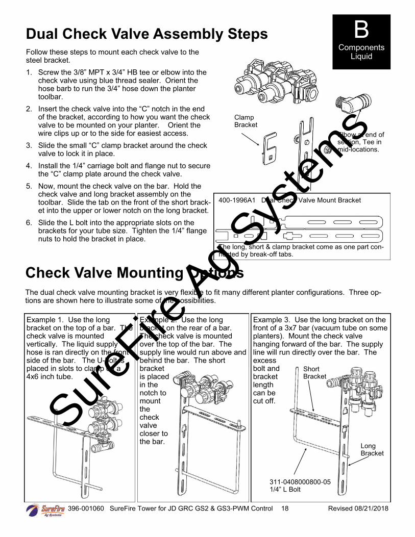
Dual Check Valve Assembly Steps Follow these steps to mount each check valve to the steel bracket.
1. Screw the 3/8” MPT x 3/4” HB tee or elbow into thecheck valve using blue thread sealer. Orient thehose barb to run the 3/4” hose down the plantertoolbar.
2. Insert the check valve into the “C” notch in the endof the bracket, according to how you want the checkvalve to be mounted on your planter. Orient thewire clips up or to the side for easiest access.
3. Slide the small “C” clamp bracket around the checkvalve to lock it in place.
4. Install the 1/4” carriage bolt and flange nut to securethe “C” clamp plate around the check valve.
5. Now, mount the check valve on the bar. Hold thecheck valve and long bracket assembly on thetoolbar. Slide the tab on the front of the short brack-et into the upper or lower notch on the long bracket.
6. Slide the L bolt into the appropriate slots on thebrackets for your tube size. Tighten the 1/4” flangenuts to hold the bracket in place.
Clamp Bracket
400-1996A1 Dual Check Valve Mount Bracket
The long, short & clamp bracket come as one part con-nected by break-off tabs.
Elbow at end of section, Tee in mid-locations.
Check Valve Mounting Options
The dual check valve mounting bracket is very flexible to fit many different planter configurations. Three op-tions are shown here to illustrate some of the possibilities.
Example 1. Use the long bracket on the top of a bar. The check valve is mounted vertically. The liquid supply hose is ran directly on the front side of the bar. The U-bolt is placed in slots to clamp on a 4x6 inch tube.
Example 2. Use the long bracket on the rear of a bar. The check valve is mounted over the top of the bar. The supply line would run above and behind the bar. The short bracket is placed in the notch to mount the check valve closer to the bar.
Example 3. Use the long bracket on the front of a 3x7 bar (vacuum tube on some planters). Mount the check valve hanging forward of the bar. The supply line will run directly over the bar. The excess bolt and bracket length can be cut off.
311-0408000800-051/4” L Bolt
Short Bracket
Long Bracket
B Components
Liquid
SureFire
Ag Sys
tems

396-001060 SureFire Tower for JD GRC GS2 & GS3-PWM Control 19 Revised 08/21/2018
Connection to Keeton Seed Firmer, Rebounder Seed Covers or through thin wall stainless steel tubes
1. Mount the Keeton Seed Firmer or RebounderSeed Cover.
2. Route the tube included in the above kit asinstructed.
3. Attach the 1/4” tube to the 1/4” QC Y dividerfitting.
4. Zip all tubing to the planter and row unit in asmany locations as possible.
For thin wall stainless steel tubes, you can push the 1/4” black tubing all the way through the stainless steel tube so fertilizer will run directly from the tubing onto the ground.
1/4” Tubing—Included in Keeton or Rebounder. Can use 1/4” black tubing from SureFire kit. Any length allowed.
113-19-025025025Y Divider - 1/4” QC
Dual Metering Tube
Option 1: QC Fitting attaches to SS Tube
113-15-038025 Reducing StraightConnector 3/8” QC x 1/4” QCPush 3/8” end onto SS tube
Connection to Totally Tubular or other heavy wall Stainless Steel Tube Ground Application Devices
When using a 3/8” OD stainless steel tube to apply fertilizer to the ground, there are two options for the de-livery tube plumbing. If the tube ID is less than 1/4” (tubing will not fit inside tube) this attachment method must be used. The description following is for Option 1. See bottom right picture for Option 2. 1. Use the 1/4” x 3/8” QC fitting shown. Push the 3/8” end onto the stainless steel tube. (Hint: if the fit-
ting slips off the stainless steel tube, use sandpaper or a file to roughen the end of the tube slightly)2. Use a short piece of 1/4” black tubing to connect the Y fitting to the reducer fitting on the stainless steel
tube.3. Zip all tubing to the planter and row unit in as many locations as possible.
Dual Metering Tube
1/4” Black Tubing—any length allowed
113-19-025025025Y Divider -1/4” QC
113-19-038038038Y Divider -3/8” QC
Option 2: 3/8” Hose attaches to SS Tube
113-03-0380253/8” Stem x 1/4” QCReducer (qty. 2)
113-01-0380383/8” Stem x 3/8”Hose Barb
3/8” Hose, attach to tube with hose clamp
B Components
Liquid
SureFire
Ag Sys
tems

396-001060 SureFire Tower for JD GRC GS2 & GS3-PWM Control 20 Revised 08/21/2018
John Deere Rate Controller for GS2 & GS3
John Deere Rate Controller
37 Pin Connector (on John Deere Harness)
SureFire adapter for John Deere Rate Controller - 37 pin to twin 16 pins, SureFire PN 201-215465Y2
Section Valve Connection (no swivel nut, not used in single section configuration)
Pump Connection (with swivel nut)
SureFire Fertilizer Systems begin at the John Deere Rate Controller, which you will need to purchase from your John Deere dealer. The picture below shows the John Deere Rate Controller. A John Deere Rate Controller can control one product. Therefore, if you were applying two liquid fertilizers on your planter, you will need three rate controllers, one for seed and two for liquid fertilizer. The John Deere Rate Controller communicates with the John Deere GS2 or GS3 display in the cab.
The harness coming from the rate controller is a 37 pin Amp connector. SureFire Fertilizer System harnesses begin at this 37 pin connector. The following page shows a system layout to illustrate how the harnessing is connected to all components. Detailed harness drawings follow for information and troubleshooting.
Instructions for setting up the GS2 or GS3 display are in Section F. Detailed screen shots of the display are included showing exactly what settings are required and recommended for SureFire Fertilizer Systems.
See your John Deere Rate Controller Operator’s Manual for more setup and operating instructions.
D Wiring & Elec.
SECTIONS 1-6
PUMP
SECTIONS 7-12
37 Pin Round – AMPMale pins in male body (with
threads for swivel nut)
GRC
Pump Connection (12-pin)
213-00-3765Y1 –Gen 2 Adapter harness37-pin to 12-pin Pump and 14-pin Sec-tion connectors
SureFire
Ag Sys
tems

396-001060 SureFire Tower for JD GRC GS2 & GS3-PWM Control 21 Revised 08/21/2018
Tower & John Deere Rate Controller Layout Control: PWM EPD Sections: 3
207-3461Y1 Final Pump HarnessOR 207-215223Y2
Pressure
Use 16 Pin Exten-sion cables, P/N 206-16-xxxxxx, toreach Tower orvalve location
Section Valves
213-00-3765Y1 37-pin to 12-pin and 14-pinAdapter Harness
OR 201-215465Y2 37-Pin to Twin 16-Pin Adapter
Harness
Can use 3-Pin Weatherpack Extension cables to reach section valves
Means connector not used in this configuration.
P/N 207-215466Y2 for 2-6 Sections
1 2 3 4 5 6
PWM
Flow
Pressure
John Deere Rate Controller
GS2 or GS3 in cab
John Deere Harnesses
Section Valves are optional. If not dividing into sections, leave cap on
‘Sections’ branch of 37 to Twin 16 adapter.
Substitute P/N 207-215467Y2 for 7-10 Sections
Implement Lift Switch Con-nector (on JD Harness) - Only one implement lift switch is required per implement.
D Wiring & Elec.
207-3463Y1 FinalSection HarnessOR 207-215466Y2
SureFire
Ag Sys
tems

396-001060 SureFire Tower for JD GRC GS2 & GS3-PWM Control 22 Revised 08/21/2018
40 Amp PWM EPD (Pulse Width Modulated Electric Pump Driver) Item Number: 205-19024 with Anderson connectors (replaces 205-18385 with 480 MP connectors)
D Wiring & Elec.
40 Amp in-line fuse
EPD Power Harness PN 205-3118Y1 (20 feet) -connect to tractor battery.This is 6 AWG wire.
Plug in 1 pump directly OR plug in 2 pumps with “Y” cable PN 205-3116Y1.
Use EPD Power Harness Extensions as needed (These have Anderson Connedtors) Wire Size
206-02-3120Y1 1’ Extension 10 gauge
206-02-3121Y1 5’ Extension 10 gauge
206-02-3122Y1 10’ Extension 8 gauge
206-02-3123Y1 20’ Extension 8 gauge
206-02-3124Y1 30’ Extension 30’ and longer—6 gauge
206-02-3125Y1 40’ Extension
206-02-3126Y1 50’ Extension
206-02-3127Y1 60’ Extension
206-02-3128Y1 2’ Anderson Ext w/ Power Switch-8 AWG
SureFire recommends a single long extension harness as multiple connectors will reduce voltage, increase current and hurt performance of your electric pump system.
Troubleshooting Tip: If the pumps won’t run, connect the power and pump connector directly together to give pumps full 12 volts directly from battery. This will tell you if the pumps are the problem or if something else is wrong. The pumps will be running at full speed, so don’t leave them connected this way for long.
Use the test connector on the line from the battery to test the voltage under load.
The Electric Pump Driver powers 1 or 2 electric pumps by providing a pulse width modulated signal to control pump speed. It needs to have a power connection and wiring capable of carrying up to 40 amps of current. It must be connected directly to the tractor battery. SureFire recommends 10 gauge wire (or heavier) if extending harnesses in the field.
PWM Connection on harness 207-3461Y1 or 207-215223Y2
Beginning in late 2015, these four connectors are Anderson connectors
PWM
Voltage test point
205-19024
Power In
Pump Out
SureFire
Ag Sys
tems

396-001060 SureFire Tower for JD GRC GS2 & GS3-PWM Control 23 Revised 08/21/2018
SureFire
Ag Sys
tems

396-001060 SureFire Tower for JD GRC GS2 & GS3-PWM Control 24 Revised 08/21/2018
John Deere GreenStar Rate Controller Wiring Schematics
Your John Deere system may have one of the following two sets of harnesses. The first set is being introduced during the 2018 season. The second set is the legacy set that has been used for several years.
New JD GreenStar Rate Controller (GRC) harnesses for the 2018 season:
Adapter Harness
213-01-3765Y1 JD Rate Controller Adapter harness with 12-pin Product and 14-pin Section connectors
Pump Harness
207-3461Y1 12-pin Final Cable for Tower with 1 or 2 Section Valves (PWM, Flow, Pressure, Sections 1 and 2)Or
207-3462Y1 12-pin Final Cable for SureFire Liquid System (PWM, Flow, Pressure, Pump RPM)
Section Harness (if needed)
207-3463Y1 14-pin 6-section Final Cable
John Deere GreenStar Rate Controller (GRC) Legacy Harnesses
Adapter Harness
201-215465Y3 JD Rate Controller to twin 16-pin AMP connectors
Pump Harness
207-215223Y2 PWM Pump Cable
Section Harness
207-215466Y2 16-pin 6-Section Harness
D Wiring & Elec.
213-00-3765Y1
207-3461Y1
207-3463Y1
37-pin connectsto GRC
SureFire
Ag Sys
tems

Wire 18AWG unless otherwise
specified
John Deere Greenstar Rate Controller Adapter Cable 37‐pin to 12‐pin Product and 14‐pin Sections
213‐00‐3765Y1
8/28/2017
Mark Wolters213‐00‐3765Y1
John Deere Greenstar Rate Controller Adapter Cable 37‐pin to 12‐pin Product and 14‐pin Sections
Part No:
Description:
Drawn By:
Last Edit Date:
Page of PagesCopyright 2017 SureFire Ag Systems, Reproduction or other use of drawing
without express written permission from SureFire Ag Systems is forbidden
Revision A‐01
25
37 Pin Round – AMPMale pins in male body (with
threads for swivel nut)
1
WHT/BLU
BLU
2
3
BRN4
5
6
7
8
9
10
12
13
14
PUR
15
16
17
18
19
20
21
28
31
36
37
YEL
GRN
BLK/WHT
BRN/WHT
WHT/BLK
WHT/BRN
PNK
BLU/WHT
BLK 14 AWG
BLK 14 AWG
BLK
11
BLU
WHT/GRN
RED 14 AWG
RED 14 AWG
PUR/WHT35
Valve GND
Valve GND
Valve Power
Section 1
Section 2
Section 3
Section 4
Section 5
Section 6
Servo +/ PWM
Servo ‐/ PWM
Flow Return
Flow GND
Flow Signal
Pressure 1 Signal
Pressure 2 Signal
Power
Power
Section 7
Section 8
Section 9
Section 10
32
33
34
29
30
22
23
24
25
26
27
A
B
C
D
E
F
G
H
J
K
L
M
Sect 1
Sect 3
Sect 2
Sect 4
Sect 5
Sect 6
HC PWR 1
HC PWR 2
PWM 1 (+)
HC GND 2
BRN
RED 14 AWG
BLK 14 AWG
BLK
BLU
BLK/WHT
SECTIONS 1‐6
BRN/WHT
BLU/WHT
RED 14 AWG
Pressure 2
AUX/Dump Valve
PUR/WHT
BLK 14 AWG
WHT/GRN
14‐pin Deutsch HDP24‐18‐14PE
N
P
HC GND 1
PWM 1 (‐)
YEL
GRN
1
2
3
4
5
6
+12V DC
Flow Signal 1
GND
Pressure 1
PWM (+)
PWM (‐)
RED
BLK
BLU
PUR
YEL
GRN
PUMP
12‐Pin Deutsch FemaleDT06‐12SA
7
8
9
10
11
12
Section 1
Section 2
BLK
BRN
A
B
C
D
E
F
G
H
J
K
L
M
Sect 7
Sect 9
Sect 8
Sect 10
HC PWR 1
HC PWR 2
PWM 1 (+)
HC GND 2
WHT/BRN
RED 14 AWG
BLK 14 AWG
WHT/BLU
PNK
SECTIONS 7‐12
RED 14 AWG
Pressure 2
AUX/Dump Valve
PUR/WHT
BLK 14 AWG
WHT/GRN
14‐pin Deutsch HDP24‐18‐14PE
N
P
HC GND 1
PWM 1 (‐)
WHT/BLK
GRC
RED 14 AWG
SureFire
Ag Sys
tems

Wire 18AWG unless otherwise
specified
Final Cable for Tower With 1-2 Section Valves (pwm, flow, pres., sec 1, sec 2, fill flow)
207-3461Y1
Final Cable for Tower With 1-2 Section Valves (pwm, flow, pres., sec 1, sec 2, fill flow)
207-3461Y1
10/26/2017
Brandon Cavenee
Final Cable for Tower With 1-2 Section Valves (pwm, flow, pres., sec 1, sec 2, fi ll flow)
Part No:
Description:
Drawn By:
Last Edit Date:
Page of PagesCopyright 2016 SureFire Ag Systems, Reproduction or other use of drawing
without express written permission from SureFire Ag Systems is forbidden
Revision A-0110/26/2017
Brandon Cavenee
Final Cable for Tower With 1-2 Section Valves (pwm, flow, pres., sec 1, sec 2, fi ll flow)
Part No:
Description:
Drawn By:
Last Edit Date:
Page of PagesCopyright 2016 SureFire Ag Systems, Reproduction or other use of drawing
without express written permission from SureFire Ag Systems is forbidden
Revision A-01
26
PWM
A
150 MP Tower 2-PIN
B
PWM +
PWM -
PWM
A
150 MP Tower 2-PIN
B
PWM +
PWM -
YEL
GRN
PWM
A
150 MP Tower 2-PIN
B
PWM +
PWM -
YEL
GRN
7
8
BLKA
Signal
+12V DC
WP TOWER 3-PIN
B
CGND
SECTION 2
RED
WHT/BRN
BLKA
Signal
+12V DC
WP TOWER 3-PIN
B
CGND
SECTION 2
RED
WHT/BRN
BLKA
Signal
+12V DC
WP TOWER 3-PIN
B
CGND
SECTION 1
RED
WHT/BLK
BLKA
Signal
+12V DC
WP TOWER 3-PIN
B
CGND
SECTION 1
RED
WHT/BLK
PUR/WHT
RED
BLK
BLU
YEL
DRK BLU
GRN
1
2
3
4
5
6
+12V DC
Flow Signal
GND
Pressure
PWM (+)
PWM (-)
DEUTSCH 12-pin DT04-12P
Pump
7
8
9
10
11
12
Fill Flow
Pump RPM
Bin Level
Open
Section 1
Section 2
1
2
3
4
5
6
+12V DC
Flow Signal
GND
Pressure
PWM (+)
PWM (-)
DEUTSCH 12-pin DT04-12P
Pump
7
8
9
10
11
12
Fill Flow
Pump RPM
Bin Level
Open
Section 1
Section 2
WHT/BLK
WHT/BRN
1 GND
+12V
AMP SUPER SEAL TOWER 3-PINBLK
RED2
Flowmeter
3 SignalBLU
1 GND
+12V
AMP SUPER SEAL TOWER 3-PINBLK
RED2
Flowmeter
3 SignalBLU
1 GND
+12V
AMP SUPER SEAL TOWER 4-PINBLK
RED2
Fill Flowmeter
3 SignalDRK BLU
4 Open
1 GND
+12V
AMP SUPER SEAL TOWER 4-PINBLK
RED2
Fill Flowmeter
3 SignalDRK BLU
4 Open
Pressure
A
150 MP SHROUD 3-PIN
B
C
Pressure
A
150 MP SHROUD 3-PIN
B
C
RED
BLK
Pressure
A
150 MP SHROUD 3-PIN
B
C
RED
BLK
Signal
+12V
GND
Pressure
A
150 MP SHROUD 3-PIN
B
C
RED
BLK
Signal
+12V
GND
Include Dust Cap
PUR/WHT
SureFire
Ag Sys
tems

Wire 18AWG unless otherwise
specified
Final Cable for SureFire Liquid Pump System (pwm, flow, pres., pump rpm, fill flow)207-3462Y1
10/31/2016
Brandon Cavenee207-3462Y1
Final Cable for SureFire Liquid Pump System (pwm, flow, pres., pump rpm, fill flow)
Part No:
Description:
Drawn By:
Last Edit Date:
Page of PagesCopyright 2016 SureFire Ag Systems, Reproduction or other use of drawingwithout express written permission from SureFire Ag Systems is forbidden
Revision A-01
27
123456
+12V DC
Flow SignalGND
PressurePWM (+)PWM (-)
RED
BLK
BLU
PUR
YEL
DRK BLU
1 GND+12V
AMP SUPER SEAL TOWER 3-PINBLK
RED2
Flowmeter
3 SignalBLU
PWM
A150 MP Tower 2-PIN
BPWM +PWM -
YEL
GRN
Pressure
A150 MP Shroud 3-pin
BC
Signal+12VGND
PUR
RED
BLK
DEUTSCH 12-pin DT04-12P
Pump
78
Include Dust CAP
1 GND+12V
AMP SUPER SEAL TOWER 4-PINBLK
RED2
Fill Flowmeter
3 SignalDRK BLU
4 Open
ORGA
GND
+12VWP TOWER 3-PIN
BC
Signal
Pump RPM
RED
BLK
9101112
Fill FlowPump RPM
Bin LevelOpen
Section 1Section 2
Include Dust CAP
Include Dust CAP
GRN
ORG
SureFire
Ag Sys
tems

Wire 18AWG unless otherwise
specified
14-Pin 6 Section Final Cable (6 sections, flow return, pressure)207-3463Y1
11/2/2016
Brandon Cavenee207-3463Y1
14-Pin 6 Section Final Cable (6 sections, flow return, pressure)
Part No:
Description:
Drawn By:
Last Edit Date:
Page of PagesCopyright 2016 SureFire Ag Systems, Reproduction or other use of drawingwithout express written permission from SureFire Ag Systems is forbidden
Revision A-01
28
BLK 18 AWGA
Signal
+12VWP TOWER 3-PIN
BC
GND
SECTION 6
RED 18 AWG
BLU/WHT
Provide dust caps for WP and MP connectors
A Signal+12V
150 MP SHROUD 3-PINPRP
RED 18 AWG B
PRESSURE 1
C GNDBLK 18 AWG
BLK 18 AWGA
Signal
+12VWP TOWER 3-PIN
BC
GND
FLOW RETURN VALVE
RED 18 AWG
WHT/GRN
BLK 18 AWGA
Signal
+12VWP TOWER 3-PIN
BC
GND
SECTION 5
RED 18 AWG
BRN/WHT
BLK 18 AWGA
Signal
+12VWP TOWER 3-PIN
BC
GND
SECTION 3
RED 18 AWG
BLU
BLK 18 AWGA
Signal
+12VWP TOWER 3-PIN
BC
GND
SECTION 2
RED 18 AWG
BRN
BLK 18 AWGA
Signal
+12VWP TOWER 3-PIN
BC
GND
SECTION 1
RED 18 AWG
ORG
DEFGHJKLMNP
Sect 3Sect 4Sect 5Sect 6
BRN
RED 14 AWG
BLK 14 AWG
ORG
BLU
BLK/WHT
SECTIONS 1-6
BRN/WHT
BLU/WHT
RED 14 AWG
Pressure 1Flow Return Valve
PRP
WHT/GRN
14 pin Deutsch HDP26-18-14SE
Sect 2
C
Sect 1
BAHC PWR 1
HC PWR 2HC GND 1HC GND 2
PWM -PWM +
Label: Section IN
Mates with 14 Pin
Section Connector
BLK 14 AWG
BLK 18 AWGA
Signal
+12VWP TOWER 3-PIN
BC
GND
SECTION 4
RED 18 AWG
BLK/WHT
SureFire
Ag Sys
tems

37 Pin Round – AMPMale pins in male
body (with threads for swivel nut)
Project:
Filename:
201-215465 Y2 with 2 pressure and Flow Return
GS2 Adapter Cable – 37 pin to twin 16 pins
Drawn By:
Date:
Dirk RickerRev by Mark Wolters
9/12/2012Rev 08/27/13
Page of PagesCopyright 2012-2013 SureFire Ag Systems
201-215465 Y2GS2 Adapter Cable – 37 pin to twin 16 pins
Wire Size: 18 AWG unless otherwise specified
Length: 2ft
1 GND
16 Pin Round – AMPFemale pins in female body
(with swivel nut)
Prp
Grn
2
3 Servo +/ PWMYel
4
5
6
7
8
9
10
11
12
13
14
15
16
Blk
Blu
Red 14 AWG
1
Wht/Blu
Blu
2
3
Brn4
5
6
7
8
9
10
12
13
14
Prp
15
1617
18
19
20
21
28
31
36
37
Yel
Grn
1 Valve GND
Section 2
16 Pin Round – AMPMale pins in male
body(with threads for
swivel nut)
2
3 Section 3
4
5
67
8
9
10
11
12
13
14
15
16
Blk
Section 4
Section 5Section 6
Section 7
Section 8Section 9
Section 10
Pressure 2 SignalFlow Return
Pressure 1 Signal
Valve Power
Section 1
Valve Power
Blk/Wht
Brn/Wht
Wht/Blk
Wht/Brn
Pnk
Blu/Wht
Wht/Blu
Blu
Brn
Prp/Wht
Wht/Grn
Blk/Wht
Brn/Wht
Wht/Blk
Wht/Brn
Pnk
Blu/Wht
Blk 14 AWG
Prp
Servo -/ PWM
Blk 14 AWG
Section 1Blk
Pressure 1 Signal
Flow GND
Flow Signal
Power
Red 14 AWG Mates with 215466 or
215467
Mates with 215223 or
215218
Blk 14 AWG
Blk 14 AWG
Blk
Red 14 AWG
11
Blu
Wht/Grn
Red 14 AWG
Blk
Red 14 AWG
Sections
Pump
Attach Dust cover to
Connector
Prp/Wht35
Pressure 2 SignalPrp/Wht
Valve GND
Valve GND
Valve Power
Section 1
Section 2
Section 3
Section 4
Section 5
Section 6
Section 7Section 8
Section 9
Section 10
Servo +/ PWM
Servo -/ PWM
Flow Return
Flow GND
Flow Signal
Pressure 1 Signal
Pressure 2 SignalPowerPower
29
SureFire
Ag Sys
tems
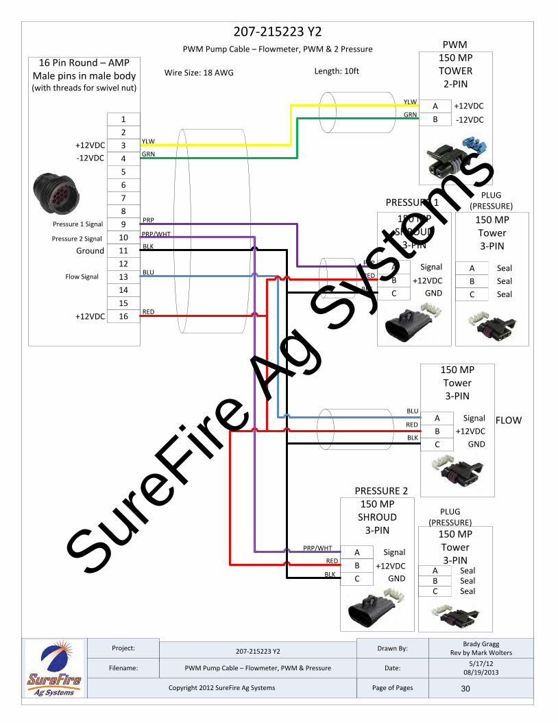
Project:
Filename:
207-215223 Y2
PWM Pump Cable – Flowmeter, PWM & Pressure
Drawn By:
Date:
Brady GraggRev by Mark Wolters
5/17/1208/19/2013
Page of PagesCopyright 2012 SureFire Ag Systems
207-215223 Y2PWM Pump Cable – Flowmeter, PWM & 2 Pressure
Wire Size: 18 AWG Length: 10ft
A +12VDC
-12VDC
150 MPTOWER2-PIN
YLW
GRNB
A Signal
+12VDC
150 MPSHROUD
3-PIN
PRP
REDB
C GNDBLK
A
+12VDC
GND
150 MPTower3-PIN
RED
BLKB
C
SignalBLU
1
16 Pin Round – AMPMale pins in male body(with threads for swivel nut)
PRP
GRN
2
3YLW
4
5
6
7
8
9
10
11
12
13
14
15
16
PWM
BLK
BLU
RED
PRESSURE 1
+12VDC
-12VDC
FLOW
Pressure 1 Signal
Ground
+12VDC
Flow Signal
PLUG (PRESSURE)
A
150 MPTower3-PIN
B
C
Seal
Seal
Seal
A Signal
+12VDC
150 MPSHROUD
3-PIN
PRP/WHT
REDB
C GNDBLK
PRESSURE 2
PRP/WHT
PLUG (PRESSURE)
A
150 MPTower3-PIN
BC
SealSealSeal
Pressure 2 Signal
30
SureFire
Ag Sys
tems

A
Signal
+12VDC
WPTOWER3-PIN
B
CGND
Project:
Filename:
207-215466 Y2
6 Section Boom Harness w/ 2 Pressure and Flow Return
Drawn By:
Date:
Dirk RickerRev. by Mark Wolters
9/12/201208/20/2013
Page of PagesCopyright 2012-2013 SureFire Ag Systems
A
Signal
+12VDC
WPTOWER3-PIN
B
CGND
A
Signal
+12VDC
WPTOWER3-PIN
B
CGND
A
Signal
+12VDC
WPTOWER3-PIN
B
CGND
A
Signal
+12VDC
WPTOWER3-PIN
B
CGND
A
Signal
+12VDC
WPTOWER3-PIN
B
CGND
207-215466 Y26 Section Boom Harness w/ 2 Pressure and Flow Return Valve
B
Signal
+12VDC
150 MPSHROUD
3-PIN
C
A
GND
16 Pin Round – AMPFemale pins in female body
(with swivel nut)
1Valve GND
Section 2 2
3Section 3
4
5
67
8
9
10
11
12
13
14
15
16
Section 4
Section 5
Section 6
Section 7
Section 8
Section 9
Section 10
Pressure 2 Signal
Flow Return Valve
Pressure 1 Signal
Valve Power
Section 1
Valve Power
SECTION 1
SECTION 2
PRESSURE 1
All wire gauge 18 AWG Unless Specified
RED 14 AWG
BLK 14 AWG
BLK
RED 14 AWG
BLK 14 AWG
BRN
RED 14 AWG
BLK 14 AWG
BLU
RED 14 AWG
BLK 14 AWG
BLK/WHT
RED 14 AWG
BLK 14 AWG
BRN/WHT
RED 14 AWG
BLK 14 AWG
BLU/WHT
RED 14 AWG
BLK 14 AWG
PRP
Wire Length: 10'Put booms 1-6, Flow Return and Pressure 1-2 in one loom 10' long
Provide dust caps for WP and MP connectors
SECTION 3
SECTION 4
SECTION 5
SECTION 6
A
Signal
+12VDC
WPTOWER3-PIN
B
CGND
FLOW RETURNValve
Signal
+12VDC
150 MPSHROUD
3-PIN
C
A
GND
PRESSURE 2
BRED 14 AWG
PRP/WHT
BLK 14 AWG
RED 14 AWG
BLK 14 AWG
WHT/GREEN
31
SureFire
Ag Sys
tems

396-001060 SureFire Tower for JD GRC GS2 & GS3-PWM Control 32 Revised 08/21/2018
Floating Ball Flow Indicators E Installation Overview
Flow Indicators are extremely flexible and can be mounted in hundreds of different configurations on various types of liquid application equipment. This page is to give you some ideas and let you customize the installation for what works best on your equipment.
16 Row Split 6 - 4 - 6 This configuration works well on a 16 row front fold planter. Each flow indicator manifold is shown fed by a cross in a single section installation. Each manifold could be fed by a section valve if desired.
12 Row Split 3 - 3 - 3 - 3 Shown here is a 12 row with four 3 row sections controlled by four section valves. Note each 6 row T-Bracket can hold two separate 3 row manifolds.
A 4 section 24 row could be similar with four 6 row manifolds on two large T-Brackets.
12 Row Dual Product Product 1 Split 4 - 4 - 4 / Product 2 Split 4 - 4 - 4 In this case each manifold would be fed by a sec-tion valve. There would be 6 total section valves (3 sections X 2 products). Most often one set (top) of flow indicators would be Full Flow for high rate fertilizer and 2nd set (bottom) would be Low Flow for starter.
NOTE: Another option is the flange can face forward so the T-Bracket could be mounted on the front side of a bar.
General Plumbing Guidelines
Fertilizer Opener, Seed Firmer, SS Tube, etc.
From Flowmeter Outlet
Minimum 3/4” hose used to feed each manifold. Length of this hose can vary significantly.
This is usually 1/4” OD tubing or 3/8” hose. Typical length is 1-4’ with check valves placedon each row that distance fromground.
This is usually 1/4” OD tubing or 3/8” hose. Maximum recommended length is 20 feet and lengths do not need to be equal.
Check valve is mounted near each row. 1/4” turn cap is always check valve outlet. Colored disc orifice can be placed under cap.
Product 1 on top
Product 2 on bottom
From Flowmeter Outlet A tee will be used in this location with 2 manifolds.
Dual Product Add-on Kit 515-1005 12 Row515-1006 6 Row
SureFire
Ag Sys
tems

396-001060 SureFire Tower for JD GRC GS2 & GS3-PWM Control 33 Revised 08/21/2018
Tower 110 & 200 Mounting Options
Tower Offset Mounting Bracket Item Number 511-1010 The Tower is available as a stand alone item.
This kit includes a bracket to mount to the top side
of a bar and hold the Tower . U-bolts are NOT
INCLUDED. They must be ordered separately
based on mounting
bar size. Multiple
slots allow the
Tower to be
mounted away from
or directly over the
bar.
E Installation Overview
500 Gallon Elliptical Cradle Tower Mounting Bracket Item Number 526-10-200500
Mounts a Tower directly to the side of the
SureFire 500 gallon elliptical tank cradle.
This bracket will mount the back of the
tower just over 9” forward of the flat bracket
mounting face.
Tractor Front Mount Elliptical Cradle Tower Mounting Bracket Item Number 511-1009 Mounts a Tower directly to the front of tractor front mount 200 & 300
gallon elliptical tank cradles. This bracket will mount the back of the
tower just over 4 1/2” forward of the flat bracket mounting face. When
using a tractor mounted tank, SureFire recommends mounting the
Tower near the tank, not back on the implement. Electric pumps work
better to push the liquid than to suck the liquid a long distance into the
pump inlet.
Tower Basic Mounting Bracket Item Number: 511-1007 (8x16 hitch)511-1008 (8x12 hitch)This kit includes a bracket to mount tothe top side of a bar or hitch and mountthe tower directly over that bar. It is of-ten used on front fold planter hitches. U-bolts to mount to two common hitch siz-es are included in the kits as labeledabove.
Tower 110 & 200 Mounting Options E Installation Overview
SureFire
Ag Sys
tems
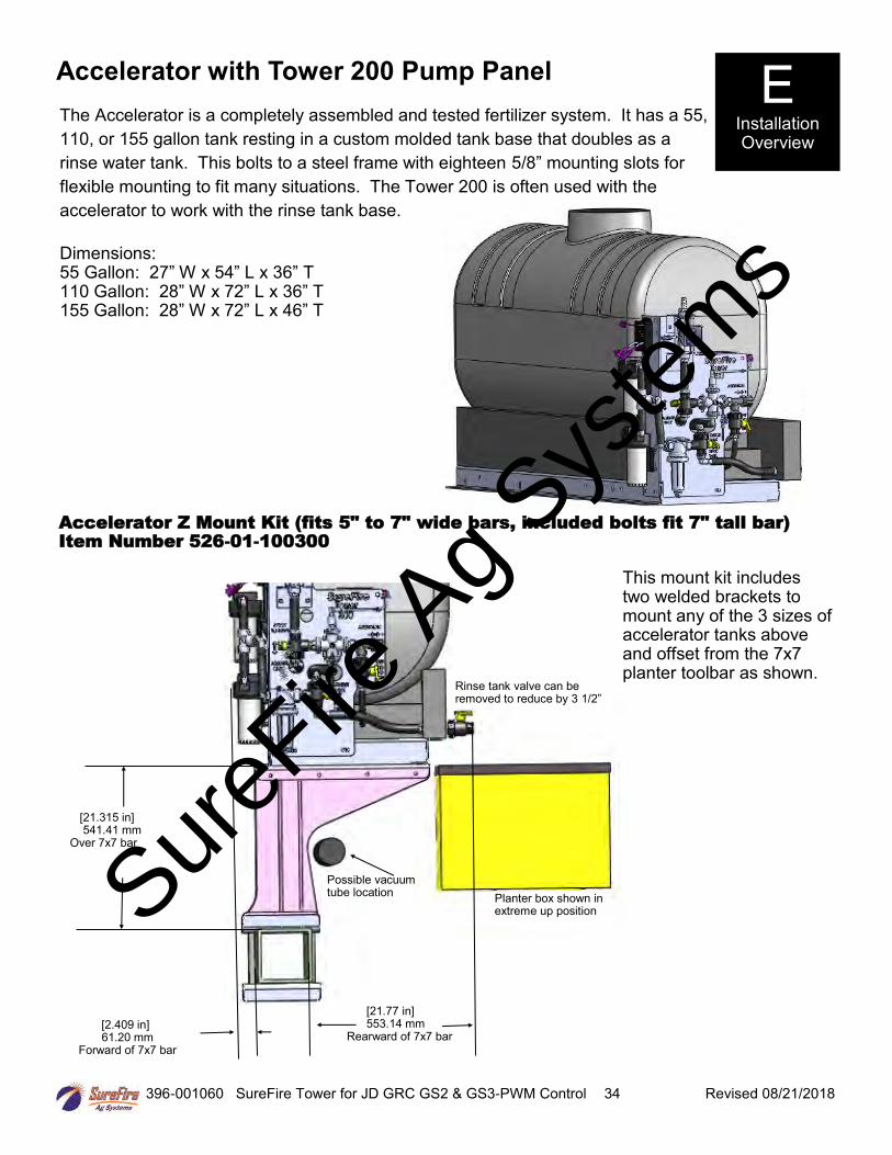
396-001060 SureFire Tower for JD GRC GS2 & GS3-PWM Control 34 Revised 08/21/2018
Accelerator with Tower 200 Pump Panel
The Accelerator is a completely assembled and tested fertilizer system. It has a 55,
110, or 155 gallon tank resting in a custom molded tank base that doubles as a
rinse water tank. This bolts to a steel frame with eighteen 5/8” mounting slots for
flexible mounting to fit many situations. The Tower 200 is often used with the
accelerator to work with the rinse tank base.
Dimensions: 55 Gallon: 27” W x 54” L x 36” T 110 Gallon: 28” W x 72” L x 36” T 155 Gallon: 28” W x 72” L x 46” T
E Installation Overview
Planter box shown in extreme up position
Possible vacuum tube location
Rinse tank valve can be removed to reduce by 3 1/2”
Accelerator Z Mount Kit (fits 5" to 7" wide bars, included bolts fit 7" tall bar) Item Number 526-01-100300
This mount kit includes two welded brackets to mount any of the 3 sizes of accelerator tanks above and offset from the 7x7 planter toolbar as shown.
[21.77 in] 553.14 mm
Rearward of 7x7 bar [2.409 in] 61.20 mm
Forward of 7x7 bar
[21.315 in] 541.41 mm
Over 7x7 bar
SureFire
Ag Sys
tems

396-001060 SureFire Tower for JD GRC GS2 & GS3-PWM Control 35 Revised 08/21/2018
Tower 110 Plumbing Overview & Valve Operation EPD (Electric Pump Driver) see section D for details
E Installation Overview
Dual 12 volt diaphragm pumps shown—SureFire systems use 1 or 2 pumps to meet specific system requirements.
Continuous recirculation flow regulated by throttling valve.
Flowmeter outlet - connect to distribution system
From fertilizer tank (3/4” Hose)
Pump Inlet Flow from filter
How to use the Recirculation Adjust Valve: Follow these steps to set the agitation adjust valve after your system is primed and tested:
1.On the Deere display go to Tests and choose Nozzle Flow Check. Enter your field operating speed andrate. Turn your master switch on. The system will now operate at your Target Rate and Test Speed.
2.Start with the recirculation adjust valve completely closed and note the slow pump speed (by pump noise).
3.Open the recirculation adjust valve slowly and note the increased pump speed and noise. Start with a halfturn of the knob. The system is applying the same amount to the ground, the pumps are now running fasterdue to more recirculation flow.
4.Set the valve to somewhere in the middle based on visual observation of agitation flow needed. (A quarterto a half turn is often sufficient recirculation to speed the pump up slightly.)
5.On your Deere display, verify the system has locked on to application rate at your agitation valve setting.
Troubleshooting: •If the system is applying a rate lower than your target, you need to close the agitation adjust valve some.
•If the system is applying a rate higher than you want and will not lock on rate, you need to open the agitationadjust valve some.
•If the rate is still fluctuating around your target and you have a two pump system, unplug one pump. At lowflows, one pump may deliver the needed rate and produce a more stable flow.
Do I need recirculation flow? Recirculation flow allows the pump(s) to run faster than if the total pump flow was applied to the ground. This is helpful when operating at very low flow rates. On a Tower 110 equipped with two 5.3 GPM pumps, you likely will NOT open the recirculation valve if applying over 1.5 GPM to the ground.
What if my product needs agitation? • Tower Electric Pump systems can provide minimal agitation. On the Tower 110, simply remove the teelocated below the recirculation valve. Connect the main hose from product tank to the filter and connect thetank agitation hose to the recirculation valve.
SureFire
Ag Sys
tems

396-001060 SureFire Tower for JD GRC GS2 & GS3-PWM Control 36 Revised 08/21/2018
Tower 200 Plumbing Overview
EPD (Electric Pump Driver) see section D for details
E Installation Overview
Dual 12 volt diaphragm pumps shown—SureFire systems use 1 or 2 pumps to meet specific system requirements.
Continuous Agitation flow regulated by agitation adjust valve
Flowmeter outlet - connect to distribution system
Agitation flow when using agitate only mode to mix prior to application
Agitation return to tank (1/2” hose)
From fertilizer tank (3/4” Hose)
Pump Outlet Flow
Continuous Agitation flow regulated by agitation adjust valve
From rinse tank base
SureFire
Ag Sys
tems
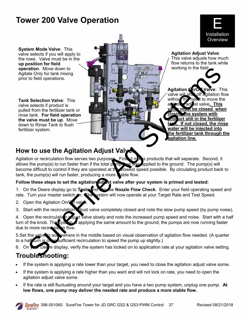
396-001060 SureFire Tower for JD GRC GS2 & GS3-PWM Control 37 Revised 08/21/2018
Tower 200 Valve Operation
System Mode Valve: This valve selects if you will apply to the rows. Valve must be in the up position for field operation. Move down to Agitate Only for tank mixing prior to field operations.
E Installation Overview
Agitation Adjust Valve: This valve adjusts how much flow returns to the tank while working in the field.
How to use the Agitation Adjust Valve: Agitation or recirculation flow serves two purposes. First, it mixes products that will separate. Second, it
allows the pump(s) to run faster than if the total pump flow was applied to the ground. The pump(s) will
become difficult to control if they are operated at the slowest speed possible. By circulating product back to
tank, the pump(s) will run faster, producing a more stable flow.
Follow these steps to set the agitation adjust valve after your system is primed and tested:
1. On the Deere display go to Tests and choose Nozzle Flow Check. Enter your field operating speed and
rate. Turn your master switch on. The system will now operate at your Target Rate and Test Speed.
2. Open the Agitation On/Off valve.
3. Start with the recirculation adjust valve completely closed and note the slow pump speed (by pump noise).
4. Open the recirculation adjust valve slowly and note the increased pump speed and noise. Start with a half
turn of the knob. The system is applying the same amount to the ground; the pumps are now running faster
due to more recirculation flow.
5.Set the valve to somewhere in the middle based on visual observation of agitation flow needed. (A quarter
to a half turn is often sufficient recirculation to speed the pump up slightly.)
6. On your Deere display, verify the system has locked on to application rate at your agitation valve setting.
Troubleshooting:
• If the system is applying a rate lower than your target, you need to close the agitation adjust valve some.
• If the system is applying a rate higher than you want and will not lock on rate, you need to open the
agitation adjust valve some.
• If the rate is still fluctuating around your target and you have a two pump system, unplug one pump. At
low flows, one pump may deliver the needed rate and produce a more stable flow.
Agitation On/Off Valve: This valve will shut off agitation flow without the need to move the agitation adjust valve. This valve must be closed when rinsing the system with product still in the fertilizer tank. If not closed, the rinse water will be injected into the fertilizer tank through the agitation line.
Tank Selection Valve: This valve selects if product is pulled from the fertilizer tank or rinse tank. For field operation the valve must be up. Move down to Rinse Tank to flush fertilizer system.
SureFire
Ag Sys
tems

396-001060 SureFire Tower for JD GRC GS2 & GS3-PWM Control 38 Revised 08/21/2018
SureFire
Ag Sys
tems

396-001060 SureFire Tower for JD GRC GS2 & GS3-PWM Control 39 Revised 08/21/2018
This manual is written for the John Deere GS2 & GS3 displays. The software version used for the screen shots is 3.13.1320 on a GS3 2630. The GreenStar Rate Controller is running version 3.40R. Your screens may vary some if using an older or newer version.
To access the GS2/GS3 Rate Controller Functions, push this button. If this button is not present the rate controller is not communicating with the GS2/GS3 display. See your John Deere operators manual or your John Deere dealer for assistance.
This button will take you to the Main Rate Controller Screen below.
Rate Controller Setup
Menu Structure
Navigation Buttons Main Rate Controller Screen
Setup
Totals
Diagnostics
Main Rate Controller Screen
Actual Rate
Target Rate
Tractor Speed Pressure (if optional pressure sen-sor installed) OR Flow in GPM (without pressure sensor).
Setup • Implement• System• Alarms• Rates
Totals • Current• Job Summaries• Lifetime Totals
Diagnostics • Readings• Tests
F Setup &
Operation
Implement Height Switch Indicator, Arrow will point up or down to indicate im-plement position if height switch is used.
Estimated Volume Remaining / Tank Refill Button (press to refill tank)
SureFire
Ag Sys
tems
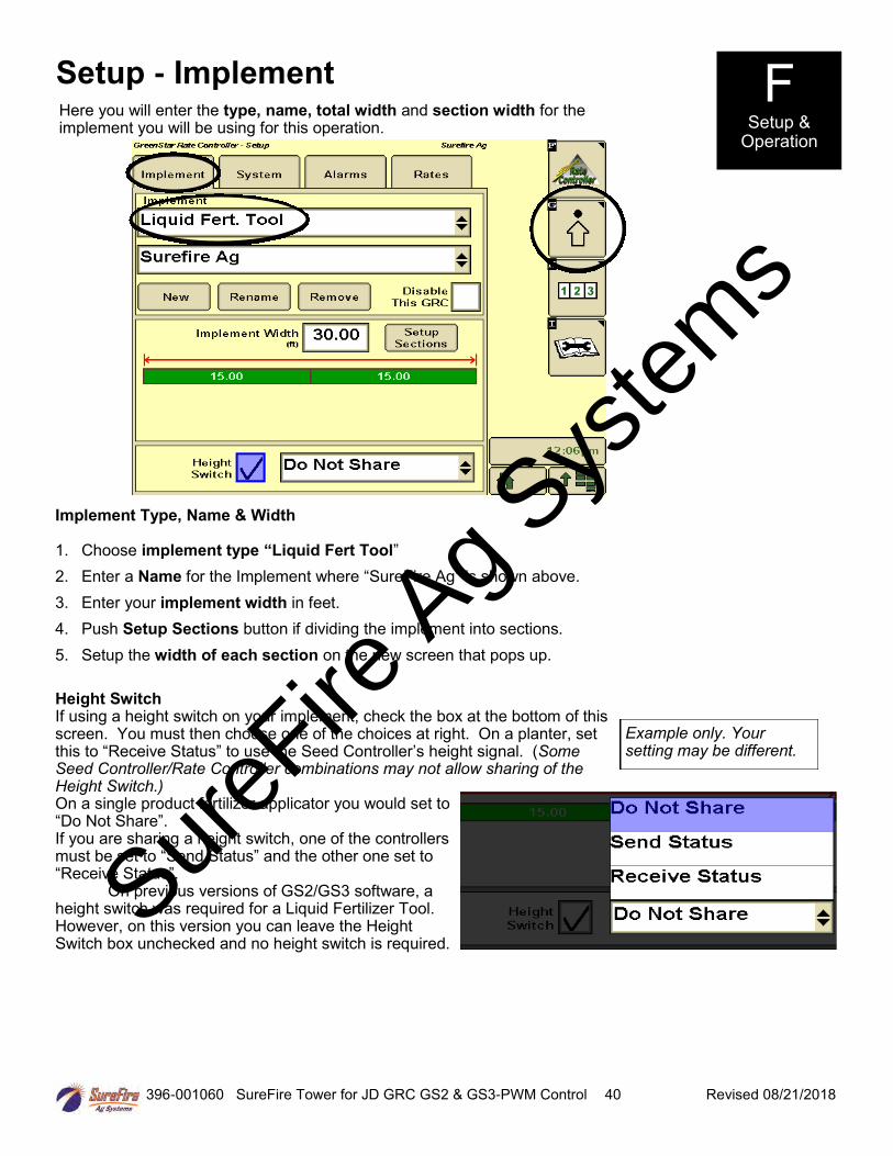
396-001060 SureFire Tower for JD GRC GS2 & GS3-PWM Control 40 Revised 08/21/2018
Implement Type, Name & Width
1. Choose implement type “Liquid Fert Tool”
2. Enter a Name for the Implement where “SureFire Ag” is shown above.
3. Enter your implement width in feet.
4. Push Setup Sections button if dividing the implement into sections.
5. Setup the width of each section on the new screen that pops up.
Height Switch If using a height switch on your implement, check the box at the bottom of this screen. You must then choose one of the choices at right. On a planter, set this to “Receive Status” to use the Seed Controller’s height signal. (Some Seed Controller/Rate Controller combinations may not allow sharing of the Height Switch.) On a single product fertilizer applicator you would set to “Do Not Share”. If you are sharing a height switch, one of the controllers must be set to “Send Status” and the other one set to “Receive Status”.
On previous versions of GS2/GS3 software, a height switch was required for a Liquid Fertilizer Tool. However, on this version you can leave the Height Switch box unchecked and no height switch is required.
Setup - Implement F Setup &
Operation
Here you will enter the type, name, total width and section width for the implement you will be using for this operation.
Example only. Your setting may be different.
SureFire
Ag Sys
tems

396-001060 SureFire Tower for JD GRC GS2 & GS3-PWM Control 41 Revised 08/21/2018
F Setup & Operation
Setup - System System setup is where you will set the John Deere Rate Controller to be compatible with the SureFire fertilizer system components.
1. Section Valve Type: 3-Wire Constant Flow: Do NOT check this box.
2. Control Valve Type: PWM Close (“close” means when the rate is zero or all sections are off, thecontroller will stop the pump)
3. Flowmeter Calibration:
• Electromagnetic Flowmeter: see chart*
4. Flowmeter Units: gal
5. Flow Return: NOT Checked
6. Pressure Sensor: Check #1 and/or #2 if using optional electronic pressure sensor(s). See next page for instructions tocalibrate pressure sensor. (When using the new 213-00-3765Y1 adapter harness, the pressureconnector on the Section harness is Pressure Sensor 2.)
7. Agitator Valve: NOT Checked
8. Flow Return: Optional Flow Return connector is on the Section harness, if using this feature.
9. See next page for instructions on “PWM Setup” & “Calibrate Pressure Sensor”
*Earlier model flowmeters (meters with white labels with black print) have different calibration numbers. See
the documentation with that flowmeter.
Flowmeter Model (GPM) (orange label or blue label)
GS2 & GS3 Flowmeter Calibration
0.13 - 2.6 3000
0.3 - 5.0 3000
0.08-1.6 22700
3000*
SureFire
Ag Sys
tems

396-001060 SureFire Tower for JD GRC GS2 & GS3-PWM Control 42 Revised 08/21/2018
F Setup &
Operation
Setup - System (continued)
From System Setup screen, push “PWM Setup” to open this screen.
1. Control Valve Calibration: 9911
The John Deere Rate Controller Control Valve Calibration can be changed to optimize performance on your specific equipment. The 4 digit number is formatted XXYZ. Increase XX to make the system respond quicker. If set too high, the actual rate will oscillate around the target. Y is the output deadband and Z is the control deadband. Generally leave these two digits low. Read your JD Rate Controller Operators Manual for more information. For example, to slow your response speed, move the number from 9911 to 8011, changing the valve response from 99 to 80. SureFire has found the fastest setting has the best performance with electric pump systems.
2. Coil Frequency: 1003. High Limit: 255 (maximum value allowed)4. Low Limit: 20 ( If you are applying a very low rate and pump
will not slow down enough, you may have to set this at 15 orelse open the Recirculation valve slightly.)
The “Calibrate PWM Limits” button is not necessary after you enter the numbers above. SureFire recommends you NOT use that procedure, and use the settings shown here for optimum performance.
5. Push the lower right button to return to the System Setup screen.
PWM Setup
Calibrate Pressure Sensor
From System Setup screen, push “Calibrate Pressure Sensor” to open this screen.
1. Be sure there is nopressure on thesensor. Unplug thesensor if not sure.
2. Select Voltage-based Calibration
2. On the screen thatopens up, enter50.0 mv/psi.
3. Push the lowerright button toreturn to theSystem Setupscreen.
4. Go to Diagnostics> Readings >Sensors/Status.The CalibrationPoints shouldshow 0 PSI = 0.00 V and 90 PSI = 4.50 V (or very close).
Tip: If the system has been running, there may be pressure in the system due to the check valves. In that case, simply unplug the sensor while this setup is being done so it will calibrate the zero point correctly.
20
SureFire
Ag Sys
tems

396-001060 SureFire Tower for JD GRC GS2 & GS3-PWM Control 43 Revised 08/21/2018
Setup - Alarms Customize your alarms and settings on this page.
1. Low Tank Level can be used by the customer if they desire, but is not required.
2. High and Low Alarm: 20% is the John Deere default and SureFire recommendedsetting. SureFire recommends these alarms be enabled (checkmark in the box).
3. Minimum Pressure: 10 psi is a safe minimum pressure to ensure all check valves (4 psi setting) are fullyopening and equal flow will go to every row. SureFire recommends turning this alarm off as each time thesystem turns on & off it willactivate, being a nuisance.
4. Maximum Pressure: 40 psi isthe recommended setting.Electric pumps will draw morecurrent and reduce output flowas pressure increases. Ifpressure is routinely over 30psi, consider changing to alarger orifice or metering tubefor optimum performance.Turn this alarm on so you arewarned when system pressureincreases for some reason (coldmorning operation may triggerthis alarm). Higher pressure isa problem only if keeps thepump from hitting the TargetRate. The pumps will operateat 50 PSI or more, but pumpoutput will be reduced aspressure increases.
Setup - Rates Enter your desired application rate(s) here.
1. Enter up to 3 rates.
2. SureFire recommendschecking the RateSmoothing box andentering 10%.
3. SureFire recommendsleaving Minimum FlowRate at 0.0. If greaterthan zero, this is theminimum flow in gallonsper minute that thesystem will NEVER golower than. Optionally, itcould be set to theminimum flow limit ofyour flowmeter.
F Setup &
Operation
SureFire
Ag Sys
tems
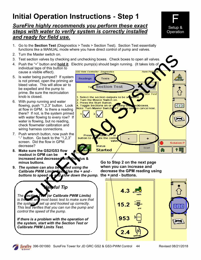
396-001060 SureFire Tower for JD GRC GS2 & GS3-PWM Control 44 Revised 08/21/2018
F Setup &
Operation
SureFire highly recommends you perform these exact steps with water to verify system is correctly installed and ready for field use.
Initial Operation Instructions - Step 1
1. Go to the Section Test (Diagnostics > Tests > Section Test). Section Test essentiallyfunctions like a MANUAL mode where you have direct control of pump and valves.
2. Turn the Master switch on.
3. Test section valves by checking and unchecking boxes. Check boxes to open all valves.
4. Push the “+” button and hold it. Electric pump(s) should begin running. (It takes lots ofindividual taps of this button tocause a visible effect).
5. Is water being pumped? If systemis not primed, open the priming airbleed valve. This will allow air tobe expelled and the pump toprime. Be sure the recirculationknob is closed.
6. With pump running and waterflowing, push “1,2,3” button. Lookat flow in GPM. Is there a readingthere? If not, is the system primedwith water flowing to every row? Ifwater is flowing, but no reading,check flowmeter calibration andwiring harness connections.
7. Push wrench button, now push the“-” button. Go back to the “1,2,3”screen. Did the flow in GPMdecrease?
8. Make sure the GS2/GS3 flowreadout in GPM can beincreased and decreased with the plus &minus buttons.
9. The system can also be tested using theCalibrate PWM Limits Test. Use the + and -buttons to speed up and slow down the pump.
Go to Step 2 on the next page when you can increase and decrease the GPM reading using the + and - buttons.
Helpful Tip
The Section Test (or Calibrate PWM Limits) is the first and most basic test to make sure that the system is set up and hooked up correctly. This test verifies that you can run the pump and control the speed of the pump.
If there is a problem with the operation of the system, start with the Section Test or Calibrate PWM Limits Test.
SureFire
Ag Sys
tems

396-001060 SureFire Tower for JD GRC GS2 & GS3-PWM Control 45 Revised 08/21/2018
Initial Operation Instructions - Step 2
1. Go to the Nozzle Flow Check (Diagnostics > Tests > Nozzle Flow Check ). This testwill operate the system as if it were running in the field at a speed and application rateyou enter.
2. Test Speed: Enter yourtypical field operatingspeed.
3. Rate: Enter your typicalapplication rate.
4. Turn the Master switchon.
5. Pump will turn on andbegin applying theentered rate.
6. Observe the system. Arethe flow and pressure onthe screen stable andreasonable? Is the flowreasonable and equalfrom each applicationpoint?
7. Repeat this test atminimum andmaximum values forboth Test Speed andRate. Rememberheavier fertilizers, suchas 10-34-0, will havehigher pressures at a given flow than water.
8. You can use this procedure with fertilizer (instead of water) to verify your minimum pressure is at least 10psi (to ensure all check valves open). Also check the maximum speed and rate to make sure pressure isunder 40 psi (to limit electrical current to pumps). When testing with water, the pressure will be muchless than it will be when using fertilizer. If the pressure is too low, all of the check valves may notopen and you may not get flow to every row.
9. While the test is running, you can go to Readings > Delivery System. Check out the PWM Duty Cycle.255 means the pumps are running full speed. This would not be a good normal operating condition. Besure the Recirculation knob is closed.
F Setup &
Operation
SureFire
Ag Sys
tems

396-001060 SureFire Tower for JD GRC GS2 & GS3-PWM Control 46 Revised 08/21/2018
Initial Operation Instructions - Step 3 This is a built-in test to calibrate the flowmeter. It also serves as a check that the entire system is setup correctly. 1. Go to Calibrate Flowmeter -
Catch (Diagnostics > Tests >Calibrate Flowmeter - Catch).The Calibrate Flowmeterscreen will pop up.
2. Number of Nozzles that willspray: Enter total rows onequipment.
3. Test Speed: Enter typicaloperating speed.
4. Rate: Enter typicalapplication rate.
5. Volume to dispense: Entervolume that you are capableof catching and measuringfrom a single nozzle (inounces).
6. Push continue button inlower right corner. Turnmaster switch on and begintest.
7. The screen to the right willpop up after test iscomplete. Enter the samplesize collected from 1 row.You need enter only 1sample measurement. TheGS2/GS3 then calculatesthe new flowmetercalibration value based on the average sample size.
With SureFire Electromagnetic flowmeters, most times the sample volume is correct. In that case, just enter the same sample size you did in #5 above to leave the calibration value unchanged. If the sample volume differs from what is expected, recheck the calibration settings. Do not change the calibration value if there is a small difference in the sample volume. It takes a fairly large sample from several rows to get a number that is accurate enough to change the default Flowmeter Calibration. SureFire recommends that you do not change the Flowmeter Calibration value unless field use shows that the amount indicated by the flowmeter is not correct. Pay close attention on the first tanks of fertilizer to verify that the display is measuring correctly.
NOTE: DO NOT ADJUST THE FLOWMETER CALI-BRATION VALUE BASED ON A CATCH OF 1 ROW ON AN IMPLEMENT. AT A MINIMUM CATCH 3-4 ROWS.
F Setup &
Operation
SureFire
Ag Sys
tems
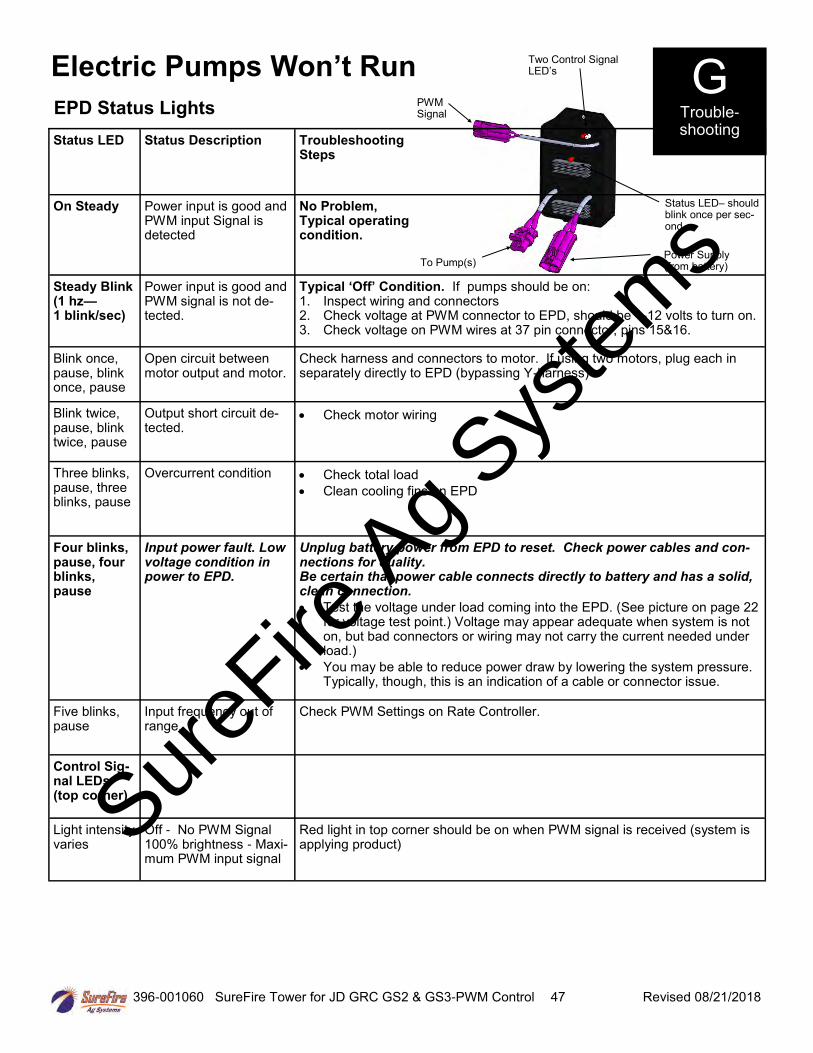
396-001060 SureFire Tower for JD GRC GS2 & GS3-PWM Control 47 Revised 08/21/2018
Status LED Status Description Troubleshooting Steps
On Steady Power input is good and PWM input Signal is detected
No Problem, Typical operating condition.
Steady Blink (1 hz— 1 blink/sec)
Power input is good and PWM signal is not de-tected.
Typical ‘Off’ Condition. If pumps should be on: 1. Inspect wiring and connectors2. Check voltage at PWM connector to EPD, should be 1-12 volts to turn on.3. Check voltage on PWM wires at 37 pin connector, pins 15&16.
Blink once, pause, blink once, pause
Open circuit between motor output and motor.
Check harness and connectors to motor. If using two motors, plug each in separately directly to EPD (bypassing Y-harness)
Blink twice, pause, blink twice, pause
Output short circuit de-tected.
• Check motor wiring
Three blinks, pause, three blinks, pause
Overcurrent condition • Check total load
• Clean cooling fins on EPD
Four blinks, pause, four blinks, pause
Input power fault. Low voltage condition in power to EPD.
Unplug battery power from EPD to reset. Check power cables and con-nections for quality. Be certain that power cable connects directly to battery and has a solid, clean connection.
• Test the voltage under load coming into the EPD. (See picture on page 22for voltage test point.) Voltage may appear adequate when system is noton, but bad connectors or wiring may not carry the current needed underload.)
• You may be able to reduce power draw by lowering the system pressure.Typically, though, this is an indication of a cable or connector issue.
Five blinks, pause
Input frequency out of range.
Check PWM Settings on Rate Controller.
Control Sig-nal LEDs (top corner)
Light intensity varies
Off - No PWM Signal 100% brightness - Maxi-mum PWM input signal
Red light in top corner should be on when PWM signal is received (system is applying product)
Electric Pumps Won’t Run
EPD Status Lights
To Pump(s)
Two Control Signal LED’s
Status LED– should blink once per sec-ond
Power Supply (from battery)
PWM Signal
G Trouble-shooting
SureFire
Ag Sys
tems

396-001060 SureFire Tower for JD GRC GS2 & GS3-PWM Control 48 Revised 08/21/2018
1. If in the field, be sure you are not in an area that the controller thinks has been covered already or that isout of bounds.
2. Go to Diagnostics, Section Test to investigate this issue.
3. In Section Test, check and uncheck the boxes. With the box checked thevalve should turn on. The valve should be off with the box not checked.
4. Check the harness connection to thatvalve. It is a 3 Pin Weather Pack connector.See Section D for wiring diagrams
5. Check voltage pin A to Pin B. Must be 12 volts, if not, go back to 37 pinand check voltage (pins 36 & 37 are +12V, pins 1 & 2 are ground).
6. If voltage is present on pins A&B of 3 pin connection to valve, then checkpin C to Pin B. This should be 12 volts when the valve is commanded onor open, this should be zero volts when valve is off or closed.
7. If signal voltage is not present to open valve, use diagrams to check atthe 16 pin , then the 37 pin for voltage on the proper pin for that section.
8. Switch connection to valve that is not working with a connection to avalve that is working.
9. If constant voltage (Pins A&B) and switched voltage (Pins C&B) are present, inspect, repair or replace thevalve.
Section Valve(s) will not move
Pin Function
A + 12 V Constant
B Ground
C + 12 V Signal
Electric pumps only run with 12 volts direct from battery
Electric Pumps Won’t Run (continued) Electric Pumps Won’t Run (continued)
1. Connect pumps and power harness back to EPD.
2. Go to Diagnostics, Section Test to investigate this issue.
3. In Section Test, hold down “+” button for a few seconds. A single tap of this button produces a very smallchange in signal to the valve, so you must hold it.
4. Remove PWM valve connector and check voltage. You will need 1-12 volts to turn pumps on.
5. If 1-12 volts is not present, check harnesses and review control valve type setup. Use harness drawingsto find the pins to check.
6. Go back to the 37 pin connector at the John Deere Rate Controller. Check voltage between pins 15 & 16,should be between 6-12 volts while in Section Test after holding “+” button.
7. If you cannot get voltage at pins 15 & 16, contact your John Deere dealer for further assistance.
Electric pumps will not turn on EPD flashing 4 times
1. Find the EPD (electric pump driver) shown above. Should have a steady blinking light inthe middle when pumps should be off. If Status LED is flashing 4 times, then pausing, EPD has trippeddue to low voltage condition. Unplug the Power Supply to the EPD to reset. If condition persists, changeto larger orifices to reduce pressure, slow down, or lower application rate. Check Power Supply cables toEPD to insure solid connections and good electrical path.
No Lights on EPD
1. There should be a steady blinking light in the middle of the EPD. If no light is ON, check the 40-amp fusein the EPD harness near the battery. Use a voltmeter to verify that there is 12-13 volts at the Power Supplyconnector that plugs into the EPD.
Will pumps run?
1. Connect the two large connectors that are plugged into the bottom of the EPD to each other (bypass themodule and supply 12 volts directly to pumps).
2. Do the pumps run? If not, check the 40 amp fuse in the EPD harness near the tractor battery. Inspectharnesses and connections. If 2 pump system, plug pumps in by themselves to check both.
G Trouble-shooting
SureFire
Ag Sys
tems

396-001060 SureFire Tower for JD GRC GS2 & GS3-PWM Control 49 Revised 08/21/2018
Application Rate Fluctuates First, you need to determine if the fluctuation is caused by the controller sending fluctuating signals to the valve. 1. Inspect & clean pump inlet strainer. Strange flow rate fluctuations are very often due
to an obstruction to the pump inlet. Inspect plumbing from tank to pump.OR 1. Go to Section Test as shown in Initial Operation, Section F.2. Turn the system on and watch the flow in GPM on the 1,2,3 screen.3. Is the flow steady within a very small range? For example a fluctuation from 2.3 to 2.5 GPM would be
considered normal. A fluctuation from 2-3 GPM is a problem. If only a small normal fluctuation is seen,skip steps 4-8 and proceed to “Application Rate Fluctuates in Field …….. “ below.
4. If there is a large fluctuation, observe the system flow. Is the discharge a steady stream? Are the flowindicator balls floating steady?
5. If visually the flow is steady, but the display reports a fluctuation in GPM, inspect the flowmeter. Seesection B for flowmeter information.
6. If visually the flow is unsteady, the flowmeter is working correctly reporting a flow problem. Is the pumpturning steady or surging?
7. Look for any type of obstruction in the pump inlet. Clean the strainer. If continually plugging the strainer,investigate fertilizer quality and necessary strainer size.
Application Rate & Flow Troubleshooting G Trouble-shooting
Application Rate fluctuates in field, but flow in Section Test mode is stable. This problem indicates the valve calibration needs changed. The system is surging because the Rate Controller is moving the pump driver or hydraulic valve too much. 1. Go to Setup - System - PWM Setup.2. Change the Valve Calibration by reducing the valve speed (first two digits). For example reduce the
number for 9911 to 8511, which changes valve speed from 99 to 85.
Application Rate is slow to get to the Target Rate 1. Check the Recirculation knob. If this is open, it will take the pump longer to get the system to Target Rate.
2. You may need to increase the Valve Calibration. Go to Setup - System - PWM Setup.
3. Change the Valve Calibration by increasing the valve speed (first two digits). For example, increase thenumber from 8511 to 9911, which changes valve speed from 85 to 99. (SureFire recommends 9911 forTower Electric Pump systems, which is the fastest Valve Calibration possible)
4. If system is too slow to get to the Target Rate when starting, go to Setup > System > PWM Setup. Raisethe Low Limit. (If Low Limit is 0, set at 25. This will start the pump at a faster speed when it initially turnson. (This number sets the low limit of your pump, so if it is set too high your pump may not be able to slowdown enough at low speed/low rate settings or with some sections turned off.)
5. Optional Method 1 to get to Target Rate faster: (Caution: You can only use this method if you have Electric SectionValves.) Go to Setup - System. Set Control Valve Type to PWM. This leaves the pump running at the last speedwhen product application is stopped. Under PWM Settings check the Pump Enable Checkbox. With the sectionvalves closed and the pump running, this can build up too much pressure in the system at times. To reduce thispressure, open the Continuous Recirculation Flow Throttling Valve on the Tower slightly (see page 30-31). Since thiswill cause continuous recirculation, it will reduce the maximum output to the rows that is attainable and the pump willrun at a higher speed all the time.
6. Optional Method 2 to get to Target Rate faster: Use the John Deere Rate Controller Flow Return feature. This willinvolve adding an additional electric valve and plumbing to return flow to the tank when product application isstopped. On the Setup - System screen, check the Flow Return box. In Setup - System, the Control Valve Typeis set to PWM. Under PWM Settings check the Pump Enable Checkbox. With the Control Valve Type set to PWM,the pump continues to run at the last speed it was running when product application was stopped. Flow at this timeis returned to the tank. When product application is resumed, flow is diverted from the tank back to the rows.
SureFire
Ag Sys
tems

396-001060 SureFire Tower for JD GRC GS2 & GS3-PWM Control 50 Revised 08/21/2018
No Flow shown on GS2/GS3 but liquid is being pumped
Flowmeter Tap Test 1. Unplug flowmeter. With voltmeter, check for 12 volts between pins 1 & 2 of flowmeter
connector (on main harness 207-3161Y1; on 215223Y2 pins B & C). If 12 volts notpresent, inspect wiring harness and troubleshoot all connections per schematic (seeSection D).
2. If 12 volts is present, then conduct a tap test. Go to setup and change the flow cal to 10. Have a secondperson watch GPM on the 1,2,3 screen while other person taps (use a short piece of wire or a paper clip)between pins 1 & 3 of flowmeter connector (Pins A & C on 215223Y2 harness). (If alone, note or reset avolume counter to 0 and check for increased volume after tapping.) A flow value should show upindicating the wiring is not damaged. Reset flow cal number after testing.
3. If GS2/GS3 responded to the tap test, your wiring to that point is good. If still not fixed, inspect adapterharness and test continuity per schematic (see Section D).
4. Replace flowmeter.
Troubleshooting Tip 1. Useful information is available at Diagnostics >
Readings. The screenshot at the right shows whichReadings are available.
2. Below are examples of some of the screens available:
G Trouble-shooting
Delivery System Check the operation of the flowmeter here. The PWM Duty Cycle gives an indication of how fast the pumps are running. The range is from 0 to 255.
Sensors/Status Check the operation of the pressure sensor here. The top number (V) will be between 0 and 5.0. The Calibration Points should indicate that 0.0 psi is 0.00 volts. The Slope should be 50.0 mv/psi.
SureFire
Ag Sys
tems

396-001060 SureFire Tower for JD GRC GS2 & GS3-PWM Control 51 Revised 08/21/2018
Fertilizer System Flow Verification
Follow the steps below: 1. Use the Fertilizer System Flow Charts on the next two pages to find your required flow. First, locate the
chart for your implement size. Next, find your operating speed on the left side and your application rateon the top. Record the flow in gallons per minute for your maximum speed and rate and your minimumspeed and rate.
A. Maximum Flow __________________ GPM (Max Rate & Max Speed)
B. Minimum Flow ___________________ GPM (Min Rate & Min Speed)
2. Locate your pump model on the chart on this page. Will the pump model provide the maximum flow youneed from above?
3. Find your flowmeter model in the chart on this page. Will the flowmeter work at both the maximum andminimum flow your recorded in step 1? If not, a different flowmeter is required.
4. If using section valves you must complete this step.
A. Minimum Flow (from above) ÷ Total Rows = ______________ GPM / Row
B. GPM / Row (from line above) x Rows per section = _______GPM / Section
Will your flowmeter measure the minimum GPM / section?
I can’t get up to my desired rate. How much flow is required? Can I achieve a new application rate with my current system? How much oil does my PumpRight need?
Number of Dia-phragms
Max Flow GPM
D70 2 15
D115 3 25
D160 4 35
D250 6 55
PumpRight Flow Table
Max Flow GPM
1-5.3 GPM Pump 3.0
2-5.3 GPM Pumps 5.0
Roller Pump 4.5
Tower (Electric Pump)Flow Table
Model Min GPM Max GPM Type
FM750LR 0.3 12 Turbine
FM750 2 40 Turbine
FlowMaster 270 Turbine 3.5 70
.13—2.6 0.13 2.6 Electromagnetic
.3—5 Electromagnetic 0.3 5.0
.6—13 Electromagnetic 0.6 13
1.3—26 Electromagnetic 1.3 26
2.6– 53 Electromagnetic 2.6 53
Flowmeter Table
G Trouble-shooting
SureFire
Ag Sys
tems

396-001060 SureFire Tower for JD GRC GS2 & GS3-PWM Control 52 Revised 08/21/2018
Use the correct implement width chart to find the required pump flow (in gallons per minute) based on travel speed and application rate
Implement Width 15 feet
Application Rate in Gallons Per Acre
MPH 2 4 6 8 10 15 20 25 30 35 40 45 50
4 0.2 0.5 0.7 1.0 1.2 1.8 2.4 3.0 3.6 4.2 4.8 5.5 6.1
4.5 0.3 0.5 0.8 1.1 1.4 2.0 2.7 3.4 4.1 4.8 5.5 6.1 6.8
5 0.3 0.6 0.9 1.2 1.5 2.3 3.0 3.8 4.5 5.3 6.1 6.8 7.6
5.5 0.3 0.7 1.0 1.3 1.7 2.5 3.3 4.2 5.0 5.8 6.7 7.5 8.3
6 0.4 0.7 1.1 1.5 1.8 2.7 3.6 4.5 5.5 6.4 7.3 8.2 9.1
6.5 0.4 0.8 1.2 1.6 2.0 3.0 3.9 4.9 5.9 6.9 7.9 8.9 9.8
7 0.4 0.8 1.3 1.7 2.1 3.2 4.2 5.3 6.4 7.4 8.5 9.5 10.6
8 0.5 1.0 1.5 1.9 2.4 3.6 4.8 6.1 7.3 8.5 9.7 10.9 12.1
9 0.5 1.1 1.6 2.2 2.7 4.1 5.5 6.8 8.2 9.5 10.9 12.3 13.6
10 0.6 1.2 1.8 2.4 3.0 4.5 6.1 7.6 9.1 10.6 12.1 13.6 15.2
Implement Width 20 feet
Application Rate in Gallons Per Acre
MPH 2 4 6 8 10 15 20 25 30 35 40 45 50
4 0.3 0.6 1.0 1.3 1.6 2.4 3.2 4.0 4.8 5.7 6.5 7.3 8.1
4.5 0.4 0.7 1.1 1.5 1.8 2.7 3.6 4.5 5.5 6.4 7.3 8.2 9.1
5 0.4 0.8 1.2 1.6 2.0 3.0 4.0 5.1 6.1 7.1 8.1 9.1 10.1
5.5 0.4 0.9 1.3 1.8 2.2 3.3 4.4 5.6 6.7 7.8 8.9 10.0 11.1
6 0.5 1.0 1.5 1.9 2.4 3.6 4.8 6.1 7.3 8.5 9.7 10.9 12.1
6.5 0.5 1.1 1.6 2.1 2.6 3.9 5.3 6.6 7.9 9.2 10.5 11.8 13.1
7 0.6 1.1 1.7 2.3 2.8 4.2 5.7 7.1 8.5 9.9 11.3 12.7 14.1
8 0.6 1.3 1.9 2.6 3.2 4.8 6.5 8.1 9.7 11.3 12.9 14.5 16.2
9 0.7 1.5 2.2 2.9 3.6 5.5 7.3 9.1 10.9 12.7 14.5 16.4 18.2
10 0.8 1.6 2.4 3.2 4.0 6.1 8.1 10.1 12.1 14.1 16.2 18.2 20.2
Implement Width 30 feet
Application Rate in Gallons Per Acre
MPH 2 4 6 8 10 15 20 25 30 35 40 45 50
4 0.5 1.0 1.5 1.9 2.4 3.6 4.8 6.1 7.3 8.5 9.7 10.9 12.1
4.5 0.5 1.1 1.6 2.2 2.7 4.1 5.5 6.8 8.2 9.5 10.9 12.3 13.6
5 0.6 1.2 1.8 2.4 3.0 4.5 6.1 7.6 9.1 10.6 12.1 13.6 15.2
5.5 0.7 1.3 2.0 2.7 3.3 5.0 6.7 8.3 10.0 11.7 13.3 15.0 16.7
6 0.7 1.5 2.2 2.9 3.6 5.5 7.3 9.1 10.9 12.7 14.5 16.4 18.2
6.5 0.8 1.6 2.4 3.2 3.9 5.9 7.9 9.8 11.8 13.8 15.8 17.7 19.7
7 0.8 1.7 2.5 3.4 4.2 6.4 8.5 10.6 12.7 14.8 17.0 19.1 21.2
8 1.0 1.9 2.9 3.9 4.8 7.3 9.7 12.1 14.5 17.0 19.4 21.8 24.2
9 1.1 2.2 3.3 4.4 5.5 8.2 10.9 13.6 16.4 19.1 21.8 24.5 27.3
10 1.2 2.4 3.6 4.8 6.1 9.1 12.1 15.2 18.2 21.2 24.2 27.3 30.3
Fertilizer System Flow Charts G Trouble-shooting
SureFire
Ag Sys
tems

396-001060 SureFire Tower for JD GRC GS2 & GS3-PWM Control 53 Revised 08/21/2018
Fertilizer System Flow Charts
Use the correct implement width chart to find the required pump flow (in gallons per minute) based on travel speed and application rate
Implement Width 40 feet
Application Rate in Gallons Per Acre
MPH 2 4 6 8 10 15 20 25 30 35 40 45 50
4 0.6 1.3 1.9 2.6 3.2 4.8 6.5 8.1 9.7 11.3 12.9 14.5 16.2
4.5 0.7 1.5 2.2 2.9 3.6 5.5 7.3 9.1 10.9 12.7 14.5 16.4 18.2
5 0.8 1.6 2.4 3.2 4.0 6.1 8.1 10.1 12.1 14.1 16.2 18.2 20.2
5.5 0.9 1.8 2.7 3.6 4.4 6.7 8.9 11.1 13.3 15.6 17.8 20.0 22.2
6 1.0 1.9 2.9 3.9 4.8 7.3 9.7 12.1 14.5 17.0 19.4 21.8 24.2
6.5 1.1 2.1 3.2 4.2 5.3 7.9 10.5 13.1 15.8 18.4 21.0 23.6 26.3
7 1.1 2.3 3.4 4.5 5.7 8.5 11.3 14.1 17.0 19.8 22.6 25.5 28.3
8 1.3 2.6 3.9 5.2 6.5 9.7 12.9 16.2 19.4 22.6 25.9 29.1 32.3
9 1.5 2.9 4.4 5.8 7.3 10.9 14.5 18.2 21.8 25.5 29.1 32.7 36.4
10 1.6 3.2 4.8 6.5 8.1 12.1 16.2 20.2 24.2 28.3 32.3 36.4 40.4
Implement Width 60 feet
Application Rate in Gallons Per Acre
MPH 2 4 6 8 10 15 20 25 30 35 40 45 50
4 1.0 1.9 2.9 3.9 4.8 7.3 9.7 12.1 14.5 17.0 19.4 21.8 24.2
4.5 1.1 2.2 3.3 4.4 5.5 8.2 10.9 13.6 16.4 19.1 21.8 24.5 27.3
5 1.2 2.4 3.6 4.8 6.1 9.1 12.1 15.2 18.2 21.2 24.2 27.3 30.3
5.5 1.3 2.7 4.0 5.3 6.7 10.0 13.3 16.7 20.0 23.3 26.7 30.0 33.3
6 1.5 2.9 4.4 5.8 7.3 10.9 14.5 18.2 21.8 25.5 29.1 32.7 36.4
6.5 1.6 3.2 4.7 6.3 7.9 11.8 15.8 19.7 23.6 27.6 31.5 35.5 39.4
7 1.7 3.4 5.1 6.8 8.5 12.7 17.0 21.2 25.5 29.7 33.9 38.2 42.4
8 1.9 3.9 5.8 7.8 9.7 14.5 19.4 24.2 29.1 33.9 38.8 43.6 48.5
9 2.2 4.4 6.5 8.7 10.9 16.4 21.8 27.3 32.7 38.2 43.6 49.1 54.5
10 2.4 4.8 7.3 9.7 12.1 18.2 24.2 30.3 36.4 42.4 48.5 54.5 60.6
Implement Width 90 feet
Application Rate in Gallons Per Acre
MPH 2 4 6 8 10 15 20 25 30 35 40 45 50
4 1.5 2.9 4.4 5.8 7.3 10.9 14.5 18.2 21.8 25.5 29.1 32.7 36.4
4.5 1.6 3.3 4.9 6.5 8.2 12.3 16.4 20.5 24.5 28.6 32.7 36.8 40.9
5 1.8 3.6 5.5 7.3 9.1 13.6 18.2 22.7 27.3 31.8 36.4 40.9 45.5
5.5 2.0 4.0 6.0 8.0 10.0 15.0 20.0 25.0 30.0 35.0 40.0 45.0 50.0
6 2.2 4.4 6.5 8.7 10.9 16.4 21.8 27.3 32.7 38.2 43.6 49.1 54.5
6.5 2.4 4.7 7.1 9.5 11.8 17.7 23.6 29.5 35.5 41.4 47.3 53.2 59.1
7 2.5 5.1 7.6 10.2 12.7 19.1 25.5 31.8 38.2 44.5 50.9 57.3 63.6
8 2.9 5.8 8.7 11.6 14.5 21.8 29.1 36.4 43.6 50.9 58.2 65.5 72.7
9 3.3 6.5 9.8 13.1 16.4 24.5 32.7 40.9 49.1 57.3 65.5 73.6 81.8
10 3.6 7.3 10.9 14.5 18.2 27.3 36.4 45.5 54.5 63.6 72.7 81.8 90.9
G Trouble-shooting
SureFire
Ag Sys
tems

396-001060 SureFire Tower for JD GRC GS2 & GS3-PWM Control 54 Revised 08/21/2018
Winterization
SureFire recommends flushing your fertilizer pump and complete system with adequate amounts of water first. Next, use RV antifreeze to winterize your system by pumping an adequate amount through all components. At the beginning of the next season, begin with water to verify the system is in working order with no leaks.
Inspect Electric Pumps
The electric pump and motor is a completely sealed component. Over time the electric motor will lose efficiency. The entire pump and motor will need replaced when it won’t efficiently produce the flow required.
Each individual pump should be able to produce more than 4 gpm of water flow with an open outlet (zero pressure). If pump falls short of this specification, replace to ensure a trouble-free fertilizing operation.
You can test the operation of each pump individually by unplugging one pump and running one pump at a time. Compare the output of each pump to each other and to the standard above.
Pre-season Service
(A little time spent here may prevent some downtime when you want to be rolling.)
1. Visually check entire system (hoses, fittings, harnesses, etc.) for any signs of wear or trouble.
2. On the display, recheck all setup screens (see Section F) to verify correct setup.
3. Fill system with water and run in Manual mode (Section Test) to verify components and system are inworking order. (May need to open air bleed valve to prime pump the first time. Be sure recirculation knobis closed.)
4. Unplug one pump at a time to verify that each pump is operating as it should. Check GPM output of eachpump.
5. Tighten all clamps. Loose clamps may be evident by leaks on the output side of the system. Looseclamps from the tank to the pump are not always apparent, but can be sources of air getting into thesystem which can create issues.
6. Push in all QuickConnect fittings to be sure the tubes are tightly seated.
7. Remove the black cap from the top of each check valve. Check the diaphragm to be sure it is intact andnot gummed up with residue. Look under the diaphragm for debris. Compress the spring in the cap to besure it moves freely. Carefully replace diaphragm and tighten cap.
8. Remove and clean the strainer. Be sure strainer is tightened securely so it will not suck air.
9. Be sure all rows are flowing and that all metering tubes/orifices are open. (Note: It will take a higher flowrate with water to create enough pressure to open all the check valves so that each row will flow.)
10. Run system with a Nozzle Flow Check with speed and rate to be used in the field.
Recommended Care and Maintenance H Maintenance
& Parts
SureFire Ag Systems 9904 Hwy 25
Atwood, KS 67730 www.surefireag.com
©2010-2018 SureFire Ag Systems
SureFire
Ag Sys
tems

396-001060 SureFire Tower for JD GRC GS2 & GS3-PWM Control 55 Revised 08/21/2018
Other issues 1. “My rate won’t go low enough. I want 8 gpa, but it won’t put down less than 11 gpa.”
A. Check Setup > Rates > Minimum Flow Rate. This can be set at 0.0 or at the low range of yourflowmeter. This is gal / min not gal / acre.
B. Check Setup > System > PWM Setup > PWM Settings > Low Limit. Default setting for JD is 15 forelectric pumps and 60 for hydraulic pumps. These may be set higher to get the pump to start faster to get toTarget Rate sooner, but if set too high, the pump cannot slow down enough when your speed drops or whensections close.
C. On a hydraulic pump, be sure the red manual override knob is down and locked on the hydraulic valve.
2. “I can’t get up to my rate. I want 12 gpa, and I can’t get more than 10 gpa.”
A. How many GPM are required to hit your rate? Is this within the pump’s specifications? On an electricpump, the output of the pump decreases as the pressure increases. Keep the pressure under 40 PSI on anelectric system. Is a recirculation valve open, allowing too much liquid to recirculate?
B. On a dual electric pump system, check each pump individually to see that each one is working atcapacity.
C. Is the strainer plugged? If too small of a mesh strainer is being used, the fluid can gel up around thescreen as the fluid is pulled through.
D. Does the pump have enough hydraulic oil to hit the desired rate? If the pump is in series behind anotherpump or motor, the hydraulic oil to this pump may be limited.
E. Check Setup > System > PWM Setup > PWM Settings > High Limit. This should be 255.
F. Go to Diagnostics > Readings > Delivery System. What is PWM Duty Cycle while the pump is running(in the field or on a Section Test or Nozzle Flow Check)? 255 means the pump is being told to run at fullspeed.
G. Run the Section Test and hold the (+) button to speed up the pump. Go to 1 2 3 to see how many GPMare being pumped. Also, check the pressure here. Check the PWM Duty Cycle.
H. Run a Nozzle Flow Check. See gal/ac, PSI, gal/min, and PWM Duty Cycle.
I. Is the flow cal correct? Is the width of the implement set correctly?
3. “It’s pretty close to the rate, but it won’t ever lock in to the rate.”
Go to Setup > Rates > Rate Smoothing. Check the box for Rate Smoothing. Put 10 in the box.
Without Rate Smoothing it is normal for the system to show the rate constantly changing small amounts as you go across the field. With Rate Smoothing, if the Applied Rate is close to the Target Rate, the display does not show all the small changes.
4. “When I start up, I get a screen that says “Solution Pump Dry”.This is not unusual on the Deere display. If the flowmeter does not show flow immediately when you start, this screen pops up. It is made to protect centrifugal pumps that can be harmed quickly if they are dry. This is not a problem for SureFire diaphragm pumps. This message may be stopped by going to Setup > System > PWM Setup > PWM Settings > Low Limit. Increase the Low Limit so the pump will start faster.
Be sure the recirculation knob is closed, so the flow goes to the row and not to recirculation.
5. “What settings do I use for the SureFire system on the original JD Rate Controller?
The full screenshots of these are in Section F of the manual that came with the system.
Here is a summary of the typical
settings: Not everything is shown
in this table. Some systems may
need to be adjusted for better
operation.
Setup Arrow Tower Electric PumpRight Hydraulic
Implement Liq Fert Tool—Set up width, sections, and height switch as needed
System—Section Valve—Control Valve
3-Wire—PWM Close
Flowmeter Calibration 3000—gal 2000—-gal
PWM Setup 9911—100—255—20 4012—100—255--60
Alarms—Pressure Sensor 10—40 15—80
Rates—Minimum Flow 0.0 or low end of flowmeter (Note: This is Gal/min NOT Gal/acre.
Rates—Rate Smoothing Check the box—10
SureFire
Ag Sys
tems

396-001060 SureFire Tower for JD GRC GS2 & GS3-PWM Control 56 Revised 08/21/2018
6. “My pressure is too high / too low.”
The pressure will be what it is depending on how hard it has to push to get the amount of liquid you are moving from the pressure sensor to where it leaves the system. This pressure will depend on the product itself, the volume (gal/min) you are moving and how much restriction there is to that flow. The orifice or metering tube will be the primary restriction, but it is possible that other parts of the system may add to the total pressure. The pressure a system develops will be less (possibly much less) with water than it will be with a fertilizer product.
What pressure is “too low”?
You need enough pressure to open the check valves. If the pressure is too low, some check valves will open before others, so that some rows may be flowing while others are not. With 4 lb check valves, we like at least 8 PSI. With 10 lb check valves, we like 15-20 PSI.
What pressure is “too high”?
There are a few products that may have flow characteristics that are better at lower rather than higher pressures. With most products that is not a concern.
The plumbing components of a SureFire system are rated at 100 PSI or above. On an electric pump system, the pump capacity decreases as the pressure increases. Our standard Tower pump has an internal 70 PSI bypass. With an electric pump, we like to see pressures from 10 to 30 PSI. If the pump has the capacity to hit the rate at higher pressures, there is not a problem with doing that, but for long-term operation it would be best to switch to a larger orifice or metering tube.
The SureFire PumpRight hydraulic pump has the ability to pump up to 290 PSI. SureFire plumbs these with a 100 PSI pressure relief valve (PRV) so that plumbing components will not be damaged if high pressure develops. Typical operating pressures with hydraulic pumps will be 20-60 PSI, but the pump will work fine at 80-90 PSI if that is needed. If continually running in that high range, consider a larger orifice or metering tube.
Lower pressure will not necessarily reduce the velocity of the output stream at the row. Conversely, higher pressure will not necessarily increase the velocity of the output stream at the row. The velocity of the output stream is determined by the volume of the flow and the size of the opening at the output. Changing the pressure by changing an orifice or metering tube upstream from the outlet will not affect the velocity of the output stream if the flow volume remains the same.
Options if pressure is too high with orifices: Use a bigger orifice. Slow down. If pressure is too low, use a smaller orifice.
With metering tube: Options if pressure is too high: Use a larger diameter tube. Shorten the tubes that are on now. Slow down. (The pressure in a metering tube is related to the viscosity of the product. Many products change viscosity as the temperature changes. A product will have a higher viscosity (and therefore higher pressure) on a cold morning than it will on a hot afternoon.)
With metering tube: Options if pressure is too low: Switch to a smaller diameter tube. Use a longer tube.
See SureFire publication “396-3269Y1 Navigating the Metering Tube Maze” for more information on how metering tube works.
See SureFire publication “396-3229Y1 Liquid System Components Overview” for a description of all the system components and additional troubleshooting/service information.
See the system manual for your system for more complete information. Manuals and publications are available for download at www.surefireag.com.
Also see the John Deere manuals for the GS3 Display and the John Deere Rate Controller for more information on the setup and operation of those components.
© 2010-2018SureFire Ag Systems
SureFire
Ag Sys
tems

396-3100Y1 QuickStart for SureFire Tower Electric Pump System for John Deere GRC-PWM Control Rev. 08/21/2018
SureFire Tower Electric Pump System
with PWM control for John Deere GRCSupplement to 396-001060
396-3100Y1 QuickStart Card
The following screenshots show the setup settings that are typically good initial settings. Actual settings on your system may vary from those shown here. Adjust settings as necessary in the field to get the best operation from your system. For more complete system information see the full manual for this system (396-001060) available at www.surefireag.com.
Setup-Implement Setup-System
Set up Height Switch as appropriate for this system Flowmeter Cal—3000 Flowmeter Units—gal
©2015-2018 SureFire Ag Systems
PWM Setup Calibrate Pressure
20
Pre-season Service —See the manual for important pre-season service tips. Troubleshooting Tips-See the manual (Section G) for more troubleshooting tips. 1. The EPD module should have a slow steady flashing light in the center LED when it is plugged into battery power.
2. If the center LED is flashing fast 4 times, followed by a short pause, and then 4 quick flashes, unplug the power fromthe battery to reset. If problem persists, this is a low voltage problem. Check cables and connections back to battery.
3. When the pumps should be running, the center LED will be steady red. The corner LED should be red to indicate it isreceiving PWM signal.
4. Plug pumps directly into power from battery to verify current is there and pumps are working.
5. Run the Section Test to verify that section valves will open and that pumps will run. When + button is held down onSection Test, the PWM voltage to EPD should go up to 12 or 13 volts.
SureFire
Ag Sys
tems

396-3100Y1 QuickStart for SureFire Tower Electric Pump System for John Deere GRC-PWM Control Rev. 08/21/2018
Setup - Alarms Setup - Rates
1
Diagnostics-Tests-Section Test Diagnostics-Tests-Nozzle Flow Check
Section Test can be used for manual operation of the system. It can be used to prime the pump on startup or to rinse the system. It is good for troubleshooting.
Use Nozzle Flow Check to see if system will lock on to a rate at a test speed. Pressure with water will be a lot lower than it will be with a heavier, thicker product.
Diagnostics—Readings—Delivery System will show details on flowmeter operation and pump speed (PWM Duty Cycle). This can be useful information for troubleshooting.
50
Flowmeter Tap Test 1. Unplug flowmeter. With voltmeter, check for 12 volts between pins 1 & 2 of flowmeter connector (pins B & C on PN
215223Y2). If no voltage, check at each connection back to Rate Controller.
2. If 12 volts is present, then conduct a tap test. Go to setup and change the flow cal to 10. Have a second person watch GPM on the 1,2,3 screen while other person taps (use a short piece of wire or a paper clip) between pins 1 & 3 of flowmeter connector (pins A & C on 215223Y2 harness). (If alone, note volume on volume counter.)
3. If GS2/GS3 responded to the tap test, your wiring to that point is good. If still not fixed, inspect adapter harness and test continuity per schematic (see Section D).
4. Replace flowmeter.
Electric Section Valve Problems 1. If one valve is not working, switch connections from that valve with a valve that is working to see if the problem is
with the valve or with getting power/signal to the valve.
2. All valves should have constant 12V power between pins A & B. When valve is commanded to turn on, there shouldbe 12V between pins B & C. Start checking at the connection closest to the valve and work back to the RateController. (See wiring pinouts in main manual.)
3. If using Auto Section Control, be sure the controller doesn’t think you are in an area already covered. Use theSection Test to open and close valves.
©2015-2018 SureFire Ag Systems
SureFire
Ag Sys
tems


