Towards Automation in Hearing Aid Design
25
Computer-Aided Design, online only http://www.sciencedirect.com/science/article/pii/S0010448511001345 Towards Automation in Hearing Aid Design Konrad Sickel a,* , Sajjad Baloch b , Rupen Melkisetoglu b , Vojtech Bubnik b , Sergei Azernikov b , Tong Fang b,* a Pattern Recognition Lab, University of Erlangen-Nuremberg, Martensstr. 3 91058 Erlangen, Germany b Imaging and Visualization, Siemens Corporate Research, 755 College Road East Princeton, NJ 08540, USA Abstract In the manufacturing of customized medical prostheses, such as in-the-ear hearing aids, the design process often is dictated by a source template repre- senting the anatomy of a patient and a set of work instructions representing the description of surface modifications. Instead of carrying out the work in- structions by hand with knife, file or drilling tools, the state-of-the-art relies on modern software tools, such as computer-aided-design and computer-aided- manufacturing. Work instructions are usually defined in terms of anatomical landmarks of a given template. Following the design phase, the virtual model of the customized prosthesis is produced by a rapid prototyping system, like selec- tive laser sintering or stereolithography. An outstanding problem in prostheses design is that the work instructions are often vaguely defined, and a suitable outcome largely depends on the knowledge, experience and skill of the designer. In this paper, we present a solution to minimize the influence of human in- teraction. Our approach involves the abstraction of the work instructions into expert system rules that exploit a robustly identified canonical set of anatomic features. The versatility of our approach lies in a priori defining an entire de- sign workflow through a rule set, thereby yielding a high degree of automation that is flexible, customizable, consistent, and reproducible. The proposed solu- tion is extensively evaluated in a real world application, and is shown to yield significant improvement in manufacturing. For instance, the consistency of the outcome was improved by about 10% and the design time was reduced by about 8.4%. Keywords: Expert systems, Rule-based systems, Shape transformation, CAD, * Corresponding authors Email addresses: [email protected] (Konrad Sickel), [email protected] (Tong Fang) Preprint submitted to Computer-Aided Design September 11, 2011
Transcript of Towards Automation in Hearing Aid Design
Computer-Aided Design,
online only http://www.sciencedirect.com/science/article/pii/S0010448511001345
Towards Automation in Hearing Aid Design
Konrad Sickela,∗, Sajjad Balochb, Rupen Melkisetoglub, Vojtech Bubnikb,Sergei Azernikovb, Tong Fangb,∗
aPattern Recognition Lab, University of Erlangen-Nuremberg, Martensstr. 391058 Erlangen, Germany
bImaging and Visualization, Siemens Corporate Research, 755 College Road EastPrinceton, NJ 08540, USA
Abstract
In the manufacturing of customized medical prostheses, such as in-the-earhearing aids, the design process often is dictated by a source template repre-senting the anatomy of a patient and a set of work instructions representingthe description of surface modifications. Instead of carrying out the work in-structions by hand with knife, file or drilling tools, the state-of-the-art relieson modern software tools, such as computer-aided-design and computer-aided-manufacturing. Work instructions are usually defined in terms of anatomicallandmarks of a given template. Following the design phase, the virtual model ofthe customized prosthesis is produced by a rapid prototyping system, like selec-tive laser sintering or stereolithography. An outstanding problem in prosthesesdesign is that the work instructions are often vaguely defined, and a suitableoutcome largely depends on the knowledge, experience and skill of the designer.In this paper, we present a solution to minimize the influence of human in-teraction. Our approach involves the abstraction of the work instructions intoexpert system rules that exploit a robustly identified canonical set of anatomicfeatures. The versatility of our approach lies in a priori defining an entire de-sign workflow through a rule set, thereby yielding a high degree of automationthat is flexible, customizable, consistent, and reproducible. The proposed solu-tion is extensively evaluated in a real world application, and is shown to yieldsignificant improvement in manufacturing. For instance, the consistency of theoutcome was improved by about 10% and the design time was reduced by about8.4%.
Keywords: Expert systems, Rule-based systems, Shape transformation, CAD,
∗Corresponding authorsEmail addresses: [email protected] (Konrad Sickel),
[email protected] (Tong Fang)
Preprint submitted to Computer-Aided Design September 11, 2011
Modeling, CAM, Automation, Application, Medical Prostheses Manufacturing,Hearing Aid Design, Feature Recognition
1. Introduction
A major development in medical prostheses manufacturing in the last twodecades has been the introduction of the computer-aided-design (CAD), and thecomputer-aided-manufacturing (CAM). The usage of these technologies precip-itated an increase in the quality and the availability of various kinds of medicalprostheses. So far, the focus of the CAD tools has been to improve the qualityand the fitting of prostheses. The basic idea is to acquire an accurate account ofthe underlying anatomy via CT or 3-D laser scan to generate a 3-D model, whichis utilized by an expert operator to design the desired target shape. Special at-tention is given to ensure the conformity of the target shape to the anatomy.Nonetheless this approach just replaces the physical cutting, grinding and filingtools with the virtual ones, controlled with a computer mouse. Neither it re-duces the amount of manual labor involved, nor does it improve the consistencyor reproducibility of the finished device. In this article, we specifically addressthese limitations of the existing CAD tools.
The general problem of automating the computer-aided-design is highly sig-nificant in various medical areas, such as hearing aid (HA) manufacturing, or-thopedics, orthotics, and orthodontics. In general, medical prostheses manufac-turing has to follow two fundamental requirements. First, a prosthesis has tofulfill its core functions, such as amplifying sound for HAs, resisting perpetualcorrosion and pressure exerted on dental prostheses or achieving the desiredshape to disguise deformations in the case of cosmetic prosthetics. Equallyimportant, it should demonstrate a tolerable degree of conformity with the un-derlying anatomy. This is particularly important to ensure that it convenientlyfits the anatomy of a patient. Due to the large amount of variability in size andshape, the design of such prostheses has traditionally been carried out manually.Thus, the resulting prosthesis has depended on the skills and the expertise ofan operator and has failed to demonstrate desirable consistency.
Our proposed solution is to formalize the available knowledge and to aug-ment the CAD system with an expert system that employs a feature detectionunit. The resulting system is capable of designing a medical prosthesis (semi-)automatically.1
The remainder of the paper is structured as follows. We start with anoverview of the related work on the automatic manufacturing of medical pros-theses and the detection of features on organic shapes. Section 3 provides abrief introduction to HA manufacturing. Section 4 formalizes the automationproblem, followed by a discussion of the employed anatomical features and the
1The framework is capable of achieving full automation, with further tweaking of thecurrently employed features and associated rules.
2

associated feature detection algorithms in Section 5. Section 6 explains theknowledge base and the construction of associated rules. Before concluding, wevalidate the proposed system in Section 7.
2. Literature Review
First attempts towards automatic manufacturing of medical prostheses wereinitiated in the late 1980s by Dooley et al., who introduced the ORTHOPERTsystem [1]. The ORTHOPERT consisted of a knowledge based system, helpingbiomedical design engineers and clinicians in the design of implantable devices.The ORTHOPERT was able to deduct from a given set of patient parametersa customized design for a femur prosthesis including a finite element analysis ofthe design. Similar work with focus on below-the-knee prostheses was done byRiechmann et al., who exploited the advantages of CAD/CAM for this task [2].
In the field of dental prostheses, Hammond and Davenport introduced theRaPiD system as a logic-based model of prostheses design [3]. RaPiD wasa declarative system that employed predicate logic for designing a removablepartial denture. A CAD/CAM solution for dental restoration was presented byZhu et al. [4]. Their work focused on the fabrication of customized dental crownsbased on CT data. Furthermore, Yan et al. [5] presented a semi-automatic rapidprototyping framework for the fabrication of removable partial dentures, whichlacks the seamless and transparent integration of expert knowledge and featuredetection compared to our approach. An extensive review of the advantagesand the limitations of the existing CAD/CAM systems for dental technologymay be found in Strub et al. [6]. So far combining knowledge-based and CADsystems resulted in applications working with non organic shapes. Lin et al. [7]developed a framework for drawing dies, which reduces the development timeand costs. Sanders et al. [8] integrated a multi-expert system into a CADsystem, which is capable of identifying designs which are easily assembled bymachines or humans. In contrast to our work, these systems focus on combiningexisting or designing non custom parts, while we focus on the automatic designof organic shapes to a unique shape using expert knowledge and on the flydetected features.
The detection of anatomical features on organic shapes is relatively less stud-ied in the context of CAD systems, where major focus has been on well definedindustrial parts. For instance, Sunil et al. [9] dealt with non-organic shapes, andZhang et al. [10] provided the detection of geometric features based on NURBSrepresentation of the underlying shapes in the form of CAD models. Ye et al. [11]went a step ahead by considering laser scanned surfaces, and employed geomet-rical feature detection for reverse engineering. The problem is more complicatedfor organic shapes, where clear boundaries between various regions usually donot exist. Similar to [11], we work with the 3D scanned surfaces of the inputshapes. But in contrast, we consider organic shapes, and focus on the forwarddesign problem, which involves the detection of anatomical features. Recently,Razdan et al. [12] addressed the problem of organic shapes, such as bones andblood vessels, where they utilized a hybrid approach that combines vertex and
3

Ear canal
Figure 1: Examples of two ear impressions (ear negatives) after triangulation. Ear impressionsdisplay large variability in size and shape. In addition, the quality of the triangulated surfacecan be poor, either due to the complexity of the underlying shape, or due to improperlyacquired impressions.
edge based feature recognition techniques. Despite some compositional similar-ities with [9, 12], we address a completely different problem, and consider morediverse set of features.
Recently, the digital manufacturing of customized hearing aids has startedto gain interest of the research community. A group led by R. Larsen workedon several topics including statistical shape models of ear impressions, analysisof deformations in the human ear canal caused by mandibular movement andthe generation of a one-size-fits-most hearing aid shell [13, 14, 15, 16]. Unal etal. [17], on the other hand, formulated the manufacturing process as a shapeestimation problem. Their statistical shape model resulted in promising re-sults on a limited set of ear impressions. Similar to their work, we validate theproposed approach with application to the customized HA design and manu-facturing. However, our method differs significantly from theirs. In contrastto their one step solution, we decompose the design process into several well-defined and physically intuitive shape modification steps. Each step, in turn, isrepresented by a set of rules in a knowledge base (KB). Each rule in conjunctionwith some well-defined anatomical features leads to a shape modification opera-tion. An inference machine of the resulting expert system applies the resultingoperations on an input shape via the integrated CAD tools. This essentiallysimulates the design work instructions, i.e., the physical steps carried out byan expert operator. An added advantage is that it allows the integration ofevery detail of the design process, including various input constraints necessaryfor perfect customization and proper functioning of the resulting device [18].Hence, our method is much more flexible as the previous approaches, whichrequire a sufficiently large training set in order to incorporate process changes.
4

Receiver
Faceplate
Figure 2: Left: Virtual placement of the electronic components in a hearing aid shell. Thecomponents include a faceplate at the very bottom of the shell, which in turn consists of abattery, a microphone, and a chip. The receiver is placed near the tip deep in the canal. Right:Three different vent styles: cylindrical vent, D-shaped vent, D-shaped vent, specifically placedon rectangular cuts on the canal to avoid occlusion.
3. Customized Hearing Aid Manufacturing
Customized HA manufacturing is a delicate, complex and time consumingprocess. First, a template shape (ear impression) is acquired. Usually, anaudiologist fills a malleable material into the ear of a patient, which is allowedto settle before it is taken out as the “negative” of the ear. The ear negative (earimpression) is then laser scanned to acquire a point cloud, which is triangulatedusing a specialized CAD software to reconstruct a mesh that represents thesurface of the outer ear as shown in Fig. 1 [19, 20]. In this paper, we assumethat the triangular mesh has already been reconstructed, and the design of theHA is required. Currently, this is done manually through the application of aseries of interactive CAD operations representing a mesh transform.
Major CAD operations include cutting, rounding and smoothing of the inputmesh. Virtual placement of electronic components (Fig. 2) is carried out toensure that the selected electronics will fit in the HA shell during the actualphysical assembly. In addition, operations to integrate other mesh structures,like the ventilation tube are performed. A vent is required, because a HAhermetically closes an ear, thereby causing pressure differences and acousticfeedback. The integration of a vent reduces these negative effects [21, 22]. Ventscome in various sizes and shapes (Fig. 2) to accommodate different feedbackproperties, and their selection and placement is crucial for proper functioning ofthe device. In summary, the design of a HA involves various constraints, suchas the target size of the device, the required amplification, vent size and style,feedback considerations and the extent of exact and comfortable fitting in theear of a patient.
Once all constraints are satisfied and a customized shell is designed, rapidprototyping techniques, such as stereolithography, are employed to create aphysical shell [23, 24]. Eventually, an operator manually assembles the shelland the associated components to construct the actual hearing aid (Fig. 3).
5

(a) (b) (c)
Figure 3: Customized in-the-ear hearing aids are manufactured in three sizes: (a) in-the-ear (ITE) devices, (b) in-the-canal (ITC) devices and (c) completely-in-the-canal (CIC) de-vices [25]. The latter ones require a removal pin for pulling them out of the ear.
4. Problem Formulation
As described above, the design of medical prostheses involves the modi-fication of a given anatomical template2 by an expert designer, driven by aset of bio-markers (features). The designer thereby relies on rules, which areeither available as work instructions or have been acquired by personal expe-rience. The problem may, therefore, be defined as that of a constrained shapetransformation. Given an unprocessed shape (surface) Ssource, represented as atriangulated mesh, the goal is to transform it into a target shape Starget, by atransformation TR. TR is described as a sequence of transformations Tr1 , Tr2 , . . .defined by a set of rules R = {r1, . . . , rn}:
Starget = TR (Ssource) . (1)
Typically, the transformation depends on constraints or options O, as wellas anatomical features F detected on the input shape. The features are utilizedby the rules to determine the eventual transformation. Eq. (1) may, therefore,be extended to include this explicit dependence:
Starget = TR (Ssource;F,O) . (2)
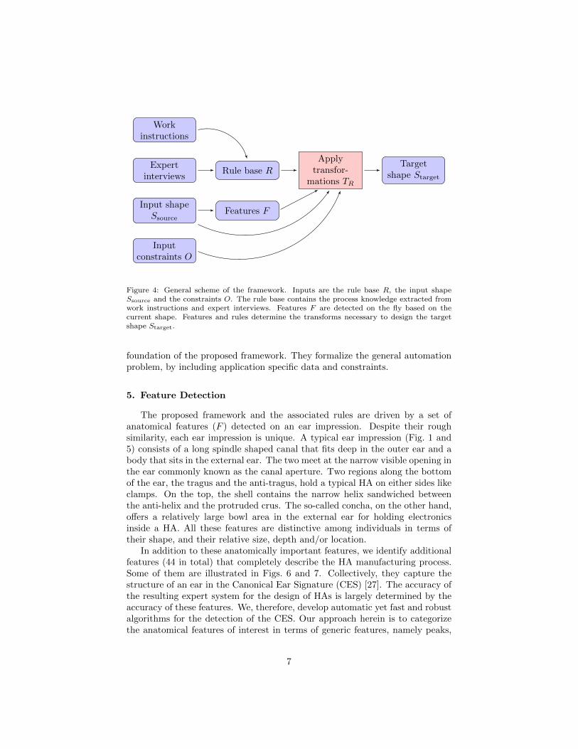
A graphic representation of Eq. (2) is given in Fig. 4. Since the transform TRis derived from rules, Eq. (2) may be rewritten as an application of a sequenceof the pertinent individual rules:
S0 = Ssource,
Si+1 = Tri (Si;Fi, O) , i = 0, . . . , j − 1; ri ∈ R,Starget = Sj ,
(3)
where Si denotes the input shape after the application of i rules. Fi, in turn,denotes the features detected on the current surface Si. Eqs. (2) and (3) form the
2The digitized impression of the anatomy of a patient.
6
Workinstructions
Expertinterviews
Rule base R
Input shapeSsource
Inputconstraints O
Features F
Applytransfor-
mations TR
Targetshape Starget
Figure 4: General scheme of the framework. Inputs are the rule base R, the input shapeSsource and the constraints O. The rule base contains the process knowledge extracted fromwork instructions and expert interviews. Features F are detected on the fly based on thecurrent shape. Features and rules determine the transforms necessary to design the targetshape Starget.
foundation of the proposed framework. They formalize the general automationproblem, by including application specific data and constraints.
5. Feature Detection
The proposed framework and the associated rules are driven by a set ofanatomical features (F ) detected on an ear impression. Despite their roughsimilarity, each ear impression is unique. A typical ear impression (Fig. 1 and5) consists of a long spindle shaped canal that fits deep in the outer ear and abody that sits in the external ear. The two meet at the narrow visible opening inthe ear commonly known as the canal aperture. Two regions along the bottomof the ear, the tragus and the anti-tragus, hold a typical HA on either sides likeclamps. On the top, the shell contains the narrow helix sandwiched betweenthe anti-helix and the protruded crus. The so-called concha, on the other hand,offers a relatively large bowl area in the external ear for holding electronicsinside a HA. All these features are distinctive among individuals in terms oftheir shape, and their relative size, depth and/or location.
In addition to these anatomically important features, we identify additionalfeatures (44 in total) that completely describe the HA manufacturing process.Some of them are illustrated in Figs. 6 and 7. Collectively, they capture thestructure of an ear in the Canonical Ear Signature (CES) [27]. The accuracy ofthe resulting expert system for the design of HAs is largely determined by theaccuracy of these features. We, therefore, develop automatic yet fast and robustalgorithms for the detection of the CES. Our approach herein is to categorizethe anatomical features of interest in terms of generic features, namely peaks,
7

(a) Illustration of the humanear [26].
(b) Triangle mesh of an ear impressionwith annotated features.
Figure 5: Anatomical features of the ear.
concavities, elbows, and ridges, and a set of derived features. The idea is thatalthough some anatomical features may not be represented by these geometricprimitives, they may still be derived from the latter or a combination of otherderived features.
5.1. Peak detection
A peak point is a prominent topological landmark on a surface S. We detectit via a height function g : S → R that assigns to each point p(x, y, z) ∈ S avalue equal to its height, g(p) := g(x, y, z) = z. For a non-degenerate surface,the critical points of g are the peaks, passes and pits of the surface. We, hence,use it for peak detection by analyzing the level sets of the height function fortopological changes. By gradually increasing g ∈ [0, H] in N steps, we findthe intersections of the surface with the corresponding planes. Intersections aresubsequently analyzed for topological changes between two successive planes. Ifa change in topology is detected, the algorithm notices the existence of a criticallevel between them, and zooms in to analyze the surface with a larger N . Theprocess is repeated until convergence to the peak point.
5.2. Concavity detection
Concavities are marked by depressions on a surface. The algorithm for con-cavity detection utilizes orthogonal scans on a surface to generate a surfaceprofile that is composed of the intersection contours. Individual contours arethen analyzed for variations in signed curvature, where the negative sign iden-tifies a concavity. First, a profile in one direction is considered, and subsectionsof contours with negative curvature are identified. For these subsections, the
8

Figure 6: Examples of peak and concavity features yielding 3-D points.
Second bend
First bend
Aperture
Crus ridge
Crus ridge top
Crus ridge bottom
Figure 7: Examples of detected elbow and ridge features.
points of least curvature are found, with their average computed as a seed point.This seed point is corrected by a scan, orthogonal to the previous scan, shiftingit towards the lowest curvature point. Consequently, the seed point is pusheddeeper in the valley. The process is repeated iteratively to achieve the abso-lute local minimum. The corrected seed point corresponds to the center of aconcavity, and is employed for region growing based on negative curvature todetermine the concave region.
9

SROI
s(0)
s(1)ht1
ht3
ht2ci(t)
cj(t)
Figure 8: Schematic view of the elbow detection algorithm in 2-D. The figure shows a sideview on a tubular surface (thick brown lines). The region of interest SROI is sliced alongthe skeleton s(t) (dotted) using planes ht (blue). Corresponding points between the profilecontours obtained by slicing with ht result in radial contours ci(t), i = 1, . . . , n (dashed). Theradial contours are parameterized and further analyzed.
5.3. Elbow detection
We are interested in the detection of elbows on somewhat tubular regions,such as the canal of an ear impression. We, therefore, identify the points thatexhibit high curvature followed by a point selection/rejection strategy that fitsa plane along the elbow.
First, the tubular part SROI ⊂ S is scanned with planes ht oriented alongits skeleton s(t) : t ∈ [0; 1], to generate a cross-sectional profile {SROI ∩ ht,∀t ∈[0; 1]} (Fig. 8). The profile contours, thus, capture information about bendson the surface. Correspondences are then established among these contoursalong the radial direction, as shown in Fig. 8, to form radial contours ci(t), i =1, . . . , n. Radial contours are parameterized, and are used to identify a set ofpoints Q of maximal curvature along these contours. However, not all pointsreliably represent an elbow, due to potential presence of the bumps. The set Qis, hence, pruned via a point rejection strategy for plane fitting similar to thedeterministic RANSAC method [28] to increase the robustness of the elbow.
5.4. Ridge detection
A ridge π : [0, 1] → S is defined as a geodesic on a surface S that passesthrough points of high curvature. Instead of using points of high curvature andthen fitting a contour through them, we use an indirect approach. It involvesfirst the detection of the starting and ending points, ps and pe respectively, ofthe ridge, followed by the computation of a connecting geodesic. To ensure thatthe geodesic passes through the ridge, we minimize the cost of going from ps tope, where the cost is defined as a weighted combination of the geodesic distance
10

and the surface curvature:
k(π) =
∫ 1
0
ω(κ(t))π(t)dt, (4)
where π(0) = ps and π(1) = pe and ω(κ(t)) is selected as a decreasing functionalof curvature (κ(t)). It is ensured that it favors only the positive mean curva-ture. Hence, the ridge is a minimizer of k, and may easily be computed for atriangulated mesh, through Dijkstra’s algorithm with curvature weighted edgelengths [29]. Consequently, the accuracy of the resulting ridge depends solelyon the robust detection of its end points, and curvature weighting ensures thatthe geodesic passes through the high curvature ridge.
5.5. Application to ear impressions
The aforementioned generic algorithms are modified slightly to adapt themto ear impressions resulting in the CES [27]. For instance, the inter-tragalnotch and the crus-side ridge require the detection of the end points of thecorresponding ridges. For the top end points, the ellipticity or curvature analysisof cross-sectional contours of the canal is used. For the bottom end points, theshell boundary is analyzed for convexity as well as its association with the toppoints. Eventually, geodesics are run from the ridge tops to the bottom pointsaccording to the algorithm described in Section 5.4.
Among the derived features, the canal-concha (or canal-crus) intersectionis detected as an intersection of two geodesics, one running along the canal (aridge), while the other traced from the concha peak (or crus).
Helix ridge is detected as the shortest curvature weighted geodesic betweenthe helix and the shell boundary. Crus area is computed as the area enclosedby appropriated weighted geodesics run between the following pairs of featurepoints: (1) center-crus-valley–helix-ridge-bottom; (2) center-crus-valley–crus-ridge-bottom; and (3) the boundary contour. Crus-concha intersection is de-tected by analyzing the tangential profile of the intersection of the shell withthe crus valley plane, see Figures 5 to 7.
6. Knowledge Base
Before describing the construction of rules, we first introduce their syntaxand how the inference machine of the expert system is integrated into the CADsoftware. Combining the knowledge base, the feature detector, and the CADsoftware results in an automation framework defined by Eqs. (2) and (3) anddepicted in Fig. 9. In this framework, the parts R, O, and F are applicationspecific. For different applications, e.g., for designing dental crowns or cran-iomaxillofacial implants, these blocks need to be replaced with appropriate rulesand features. Depending on the use case, it may require some effort in termsof feature detection and rule definition. The framework architecture, includingthe CAD software and the inference machine (interpreter), is general enough to
11

Get nextrule ri
Requestrequired
features Fi
Set up CADenvironment
ApplyTri on Si
Knowledgebase R
Inputconstraints O
Featuredetector
Currentsurface Si
Input surfaceSsource
CAD tools
Inference MachineControls all compo-nents
ri
Fi
Fi
as constants
Tri
Figure 9: Automation framework schematic: For each prosthesis design, a set of constraintsO and an input surface Ssource are fed to the KB R and to the feature detector respectively.The resulting automation is general and fixed for different inputs and prostheses designs. Theinference machine executes all applicable rules, which amounts to the application of CADoperations and consequent modification of the input shape. During the execution of rules, thefeature detector automatically updates the features if necessary. Once a rule is applied, thecurrent state of the surface Si changes. After the invocation of all pertinent rules, the finalstate is outputted as the eventual prosthesis.
handle various kinds of automated design tasks. For evaluation purposes, werestrict ourselves to the use case of customized hearing aid design.
In the current implementation, we have employed a CAD system, which issimilar to Magics by Materialise [30] or Shell Designer by 3Shape [31]. TheES uses the internal command parsing architecture to interface with the CADtools.
6.1. Knowledge base syntax and integration
The knowledge base is constructed through a procedural representation inthe form of if-then-else rules as described in [32]. In contrast to a declarativerepresentation, such a procedural knowledge representation allows the possibil-ity of defining rules that match the manual HA design process and may easily beinterpreted by the process experts. Despite its simplicity, this representation issufficiently powerful to encode the knowledge for the shell shaping process [32].
12
The rules, in turn, are transcribed by a specifically developed scripting languagewith a context free grammar similar to PASCAL.
The main advantage of developing a new scripting language lies in its simpleintegration in an existing modeling software. It allows the inclusion of newfunctionalities as the need arises, while keeping the framework as simple aspossible.
The developed language supports the standard data types, like booleans,integers, floats, strings and arrays of all types, as well as 3-D points, planes andmatrices as special data types. For each data type, the standard calculationand comparison operators are made available, which allow vector and matrixbased computations. The script language supports control structures, such asif-then-else blocks as well as for, while and repeat-until loops. Further-more, it allows the definition of functions and procedures. The script parser andinterpreter are implemented with the tools bison and flex [33]. The availablefunctions are grouped into two classes. The first class encompasses the internalfunctions, which are defined in the syntax of the scripting language. The inter-nal functions are divided further into five groups: guide, geometric, parameter,visualization and communication. They are indicated by a capital first letter.
The second class contains the logical functions, which are defined using theinternal functions and are indicated by a lowercase first letter. They are calledlogical functions because they store the logic of the design process in the rules.In other words, the internal functions provide the architecture and basic func-tionality for the rule definition and integration into the modeling software andthe logical functions store the process knowledge in the KB.
The expert system is integrated in the form of a guide, in two possible usagemodes. In the semi-automatic mode, it guides an operator through the processsteps and offers in each step the necessary CAD tools as well as a suggestedoperation. For example, if a process step requires a cutting plane, then theguide defines this cutting plane and sets up the necessary tools to cut the surface.The operator will then only need to verify the correctness of the plane beforeapplying the operation. Once the cut is applied, the inference machine willfetch the next process step. In the fully automatic mode, the verification stepis skipped and every operation is automatically applied.
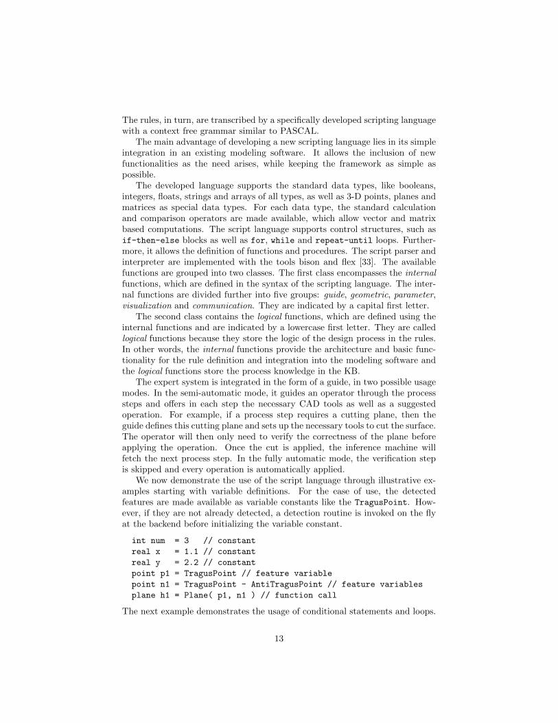
We now demonstrate the use of the script language through illustrative ex-amples starting with variable definitions. For the ease of use, the detectedfeatures are made available as variable constants like the TragusPoint. How-ever, if they are not already detected, a detection routine is invoked on the flyat the backend before initializing the variable constant.
int num = 3 // constant
real x = 1.1 // constant
real y = 2.2 // constant
point p1 = TragusPoint // feature variable
point n1 = TragusPoint - AntiTragusPoint // feature variables
plane h1 = Plane( p1, n1 ) // function call
The next example demonstrates the usage of conditional statements and loops.
13
The if conditions implement a simple number and a string comparison. Thewhile loop uses a simple number comparison, which is updated in the body ofthe loop.
if x == y then
p1 = AntiTragusPoint
endif
point n2 = Point( 0, 0, 1 )
plane h2 = Plane( p1, n2 )
while x < y do
h2 = MovePlane( h2, p1, x )
x = x + 1
endwhile
if Option(1) == "CIC" then
n2 = -n2
endif
The MovePlane is a geometric function, which modifies the given plane h2, bymoving it along its normal by x mm towards the reference point p1. Parameterfunctions, like Option, usually specify a property for a design step. Here, thenormal n2 is flipped for the CIC devices.
The logical function foo in the following example takes one input parameterof type string and returns a boolean value. The procedure foo2 has twoparameters x and option and uses foo to either add or subtract x to a globallydefined variable y.
func foo(string option) : bool
if option == "AX" or option == "AY" or
option <> "AZ" or option == "A1" and
option == "A2" then
return true
else
return false
endif
endfunc
proc foo2( int x, string option )
if foo( option ) then
y = y + x
else
y = y - x
endif
endproc
The guide functions provide the interface to the modeling and detailing functionsof the design software. Detailing and modeling describe specific phases of thedesign process. For instance, the vent is integrated by specifying its starting and
14

ending points, and then invoking the vent integration tool of the CAD system.A simplified example is given below, which triggers the vent placement rule onlywhen a vent option is available. In the opening part, it sets up the Modeling
CAD environment and displays the name of the guide step, i.e., Vent placement.In the body of this rule, just one logical function computeVentPoints( v1, v2
) is called, which computes the position of the vent end points. This informationis delivered back to the CAD software by the closing step, which automaticallyinvokes the integration of the vent into the shell.
if has_vent() == true then
OpenGuideStep(Modeling, "Vent placement")
point v1, v2
computeVentPoints( v1, v2 ) // logical function
CloseGuideStep(VentPlacement, v1, v2)
endif
Another example for a guide step with focus on the cutting and rounding toolsis the removal of the helix part for the smaller device types:
if is_itc() == true or is_cic() == true then
OpenGuideStep(Detailing, "Helix removal")
plane h1 = CrusValleyPlane // feature
point p1 = (TragusPoint + AntiTragusPoint) * 0.5
plane h2 = MovePlane( h1, p1, 1.0 )
point ref = TragusPoint // feature
int level = 1
CloseGuideStep(Round, h1, ref, level)
endif
This simplified example uses a plane as an input for the rounding tool, which isinitialized using a feature plane. To make the selection unambiguous, a referencepoint is provided together with a rounding level.
Visualization functions are used to set up the working environment for auser. This includes common functionalities like toggling the transparency of animpression in cases where components are placed.
ShowTransparent( true )
SetTool( "Round", level )
The last set of functions allows the expert system to communicate with the userand to provide information about the progress, success or failure of a processstep or the detailing or modeling procedure.
Info("text")
Warning("problem")
6.2. Construction of Rules
We adopted an iterative approach for constructing the KB as described in[32]. First, the written work instructions were directly translated into rules and
15

the resulting prototype KB was evaluated with several sample cases. With thehelp of the expert operators, the gaps in the written instructions were identifiedand filled. One immediate effect of our work was that it helped in identifyingthe ambiguities in the written work instructions. This allowed improvements inthe current instructions, which are now much more detailed and precise thanbefore. It took several iterations till the first complete KB was acquired.
Nevertheless, the performance of the eventual KB still lags behind an ex-pert operator. The main reason is the huge amount of variability in the earcanals, which may result in two problems. First, a rule can fail due to potentialinaccuracy of a detected feature. Second, a work instruction may turn out tobe too general to accommodate such variation. To improve this, we again con-sulted our experts and fine tuned the KB further. The current KB consists ofapproximately 60 guiding rules and approximately 70 logical rules.
7. Evaluation
We now carry out the validation of the proposed framework. Three kinds ofvalidations are considered. First, we focus on the evaluation of detected features.Second, we evaluate the performance of the early iterations of our KB. Third,we analyze the quality of the HAs designed through our system, via comparisonwith the manual approach. The evaluation was carried out on a standard PCconsisting of an Intel Core 2 Duo CPU and 2 GB of RAM.
7.1. Feature detection evaluation
An extensive evaluation of the feature detector was carried out in [27]. Over adataset of 198 impressions, statistical evaluation of the point and plane featureswas carried out relative to the ground truth, which was manually annotated byan expert. The curve features, on the other hand, were evaluated qualitativelyby the experts, due to the absence of corresponding ground truth data. Thesimilarity δp of the point features with the ground truth was computed as theEuclidean distance between them.
Measure µ σ
δp (point distance in mm) 1.98 2.05δor (plane orientation in degrees) 8.1 16.3δloc (plane location in mm) 1.0 1.21δsen (sensitivity) 0.83 -δspe (specificity) 0.93 -
Table 1: Results of the feature detection evaluation for the different measures. µ denotes themean value and σ the corresponding standard deviation.
For plane features, both the orientation and the location were considered.The orientation δor was compared via the angle between the plane normals.Deviation of plane locations δloc was determined by first finding the center of the
16

intersection contours of the individual planes, followed by computing the meanof the distances of the centers from their counterpart planes. Area features wereevaluated by way of the sensitivity δsen and specificity δspe, see Table 1.
For the interpretation of the results, experts were asked to provide reasonableerror tolerances for various features (3mm for location, and 15◦ for orientation).The error tolerances were then used to define two additional performance mea-sures. The detection rate ∆det was computed as the percentage of test casesfor which an algorithm successfully detected the corresponding feature. Thetolerance rate ∆tol was computed as the percentage of test cases for which thedetected feature is within the acceptable tolerance. The results indicate ac-ceptable performance for most features (overall mean tolerance rate of 87% forpoints and 83% for planes). The tolerance rate was computed over the cases,which passed the detection test. The results are provided in Table 2.
Performance measure Feature type Rate in %
∆det (detection)3-D point 98.63-D plane 98.8
∆tol (tolerance)3-D point 87.03-D plane 82.0
Table 2: Results of detection and tolerance rate.
7.2. Early evaluations of the knowledge base
For the early evaluations of the knowledge base, a simple performance ratingwas used to acquire feedback from the test users by running the automationframework in the semi-automatic mode. All users were asked to rate each guiderule according to: 0 – unusable, 1 – usable with modifications, 2 – acceptablewithout modifications and 3 – perfect. Rating value 3 was introduced to coverthe tendency of the expert designers to apply minimal modifications.
39 hearing aid orders with different constraints on the size, venting optionsand amplification were employed as test samples. In total, there were six expertusers. Their ratings are analyzed in Table 3. The overall quality is very promis-ing. On average, each guide rule suggested an acceptable solution for each step.However, for full automation, it is necessary to reach at least a rating of 2 ineach step. In this first evaluation, automation was achieved for about 14% ofthe test cases (every applied rule rated ≥ 2). The inspection of the medianrating value, m, indicates that 75% of the guide rules achieved a rating ≥ 2,which also shows that most steps were acceptable by the experts. After the firstiteration, some discrepancies were identified between the digitized rules and theoperator expectations during feedback sessions with the experts. This was re-sponsible for a lower level of quality, e.g., for optional cuts. On average most ofthe guide rules performed quite well, but needed improvement in terms of thestandard deviation, e.g., ITE anti-helix filling. A minor subset of the rules (crusscooping, CIC measured cut and ITE measured cut) suffered from the fact that
17

Rule name µ (±σ) m
All rules 1.96 ( 0.95 ) 2Canal tip cut 1.74 ( 0.98 ) 2Excess material cut 2.21 ( 0.86 ) 2ITC measured cut 2.10 ( 1.01 ) 2ITE crus scooping 1.07 ( 1.14 ) 1ITE measured cut 1.58 ( 0.93 ) 1Optional cuts 1.68 ( 0.87 ) 1Receiver hole placement 1.97 ( 1.06 ) 2Waxguard cut 2.57 ( 0.86 ) 3Canal thickening 1.72 ( 1.13 ) 2CIC measured cut 1.14 ( 0.81 ) 1ITC crus cut 2.45 ( 0.78 ) 3ITE anti-helix filling 2.25 ( 1.10 ) 3ITE cymba rounding 2.43 ( 0.77 ) 3Labeling 1.86 ( 1.26 ) 2Optional vent cuts 2.60 ( 0.76 ) 3Vent placement 2.04 ( 0.93 ) 2
Table 3: The table shows quality values given by expert operators using an early version ofthe automation framework to design a customized hearing aid. For the sake of clarity andspace, similar rules are grouped together. µ is the mean quality value of all six operators fora certain rule, σ the standard deviation and m the median.
the training set, used during rule definition, did not cover the shell variabilityfound in the validation set.
7.3. Final evaluation
For the final evaluation, we tried to avoid subjective data in contrast tothe previous experiment. Here, we relied on the fact that our industry partneremployed our framework for the manufacturing of HAs in the semi-automaticmode. The evaluation was organized in four parts. First, we analyzed thegeneral performance of the automation framework, followed by a comparisonof the consistency of design during manual and automated process. Third, thequality in terms of size was evaluated. Finally, the average time needed to designa customized HA was analyzed.
7.3.1. General performance
Using data from our industry partner, we measured the performance of theframework by counting how often a guide rule was accepted with or withoutmodifications. To accommodate the fact that every user would model a dif-ferent prosthesis, we integrated several thresholds into the measurements. Forexample, if the expert system places a cutting plane and the user modifies theplane only slightly before applying, then we count this as an acceptable solu-tion. If the modification exceeds a threshold, we count it as unacceptable. In
18

agreement with the design experts, we used the thresholds defined in Table 4.The sample data consisted of 2072 manufactured HA orders, with 35940 guide
Type Threshold
Plane Location distance ≤ 0.5 mmOrientation difference ≤ 5◦
Area Size difference ≤ 15%Point Distance ≤ 1 mm
Table 4: Thresholds used for performance analysis.
rules. The results in Table 5 show that the level of automation achieved is goodand similar for all device types. 71% of the rules were found very stable in theirperformance. 21% of them performed from very good to mediocre, with only8% resulting in poor performance. Full automation was not achieved because:
HA device type Step acceptance rate in % Fraction in %
All 71.38 100.00ITC 69.94 45.03ITE 73.60 36.82CIC 70.44 18.15
Table 5: Guide rule performance analysis.
1. Poorly acquired impressions, with gaps, extreme amount of excess mate-rial, and noise, resulted in degradation of the performance of the featuredetector. Since the entire system depends on these features, the overallperformance dropped in such cases.
2. It is possible to misuse the framework by not following the process. If astep requires canal tip rounding, but the user applies rounding elsewhereon the surface, it can destroy assumptions defined in the knowledge base.
3. The level of acceptability varies across users, as each user has his ownunderstanding and cosmetic feeling.
4. An audiologist may specify special instructions. If they cannot be trans-lated into the constraint set O, the designer has to adjust the guide rulein order to fulfill these specific constraints.
7.3.2. Consistency
To evaluate the consistency of the designs we used the following sample sets:
1. Sample set SMan consists of 25 manually designed HA shells. Each shellwas designed three times by the same user, resulting in 75 surfaces:SMan = {S1, . . . , S75}.
2. Sample set SAut consists of 25 semi-automatic designed HA shells. Eachshell was designed three times by different users, also resulting in 75 shells.
19

Sample set δmc δse δm
SMan 0.0089 0.1310 0.0675SAut 0.0016 0.1161 0.0504
Table 6: Results of the consistency analysis.
All surfaces were pre-aligned to a common coordinate space. The below de-scribed similarity measures were then computed for each pair of surfaces:
Mesh coverage. δmc is an indicator how well the shapes overlap. To computeδmc, the number of corresponding points whose distance is below a threshold isdivided by the number of corresponding points. The measure is almost 1 forshapes which are similar in size and shape, but do not match perfectly. Weselected 2mm as the threshold in our experiments.
Normalized sum of squared error. δse is similar to δmc, but instead of countingpoints, the squared error is accumulated.
Median distance. δm is defined as the median of the squared errors between thecorresponding points.
Table 6 shows that automated processing leads to superior consistency, eventhough SMan were generated by the same user. It improved the mesh coverageby about 80%, δse by more than 10%, and δm by around 25%. Large increasein δmc is due to an much more consistent placement of the faceplate (Fig. 2) inthe semi-automatic case. In the manual mode, the faceplate orientation variedsubstantially, among various designs by the same user for the same shells.
7.3.3. Quality
It is difficult to objectively evaluate the quality of a hearing aid design. Wesimplified the problem, by ignoring the cosmetic appearance, and focusing on thesize of the resulting device, since compactness forms a major design requirementfor ITE HAs. We defined five size related measures:
• The mesh size is defined as the inner surface area of the designed shell.
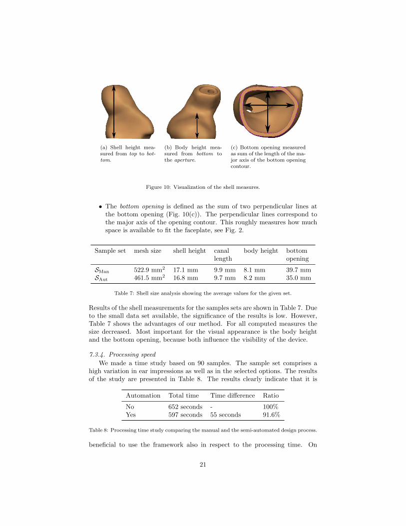
• The shell height is measured as the perpendicular distance from the bottomopening to the farthest point (Fig. 10(a)).
• The body height is measured as the perpendicular distance from the bottomopening to the lowest point on the aperture (Fig. 10(b)). This measureis more significant than the shell height, since the canal length does notinfluence the visibility of the device.
• The canal length is the distance between the lowest point on the apertureand the highest point on the shell.
20
(a) Shell height mea-sured from top to bot-tom.
(b) Body height mea-sured from bottom tothe aperture.
(c) Bottom opening measuredas sum of the length of the ma-jor axis of the bottom openingcontour.
Figure 10: Visualization of the shell measures.
• The bottom opening is defined as the sum of two perpendicular lines atthe bottom opening (Fig. 10(c)). The perpendicular lines correspond tothe major axis of the opening contour. This roughly measures how muchspace is available to fit the faceplate, see Fig. 2.
Sample set mesh size shell height canal body height bottomlength opening
SMan 522.9 mm2 17.1 mm 9.9 mm 8.1 mm 39.7 mmSAut 461.5 mm2 16.8 mm 9.7 mm 8.2 mm 35.0 mm
Table 7: Shell size analysis showing the average values for the given set.
Results of the shell measurements for the samples sets are shown in Table 7. Dueto the small data set available, the significance of the results is low. However,Table 7 shows the advantages of our method. For all computed measures thesize decreased. Most important for the visual appearance is the body heightand the bottom opening, because both influence the visibility of the device.
7.3.4. Processing speed
We made a time study based on 90 samples. The sample set comprises ahigh variation in ear impressions as well as in the selected options. The resultsof the study are presented in Table 8. The results clearly indicate that it is
Automation Total time Time difference Ratio
No 652 seconds - 100%Yes 597 seconds 55 seconds 91.6%
Table 8: Processing time study comparing the manual and the semi-automated design process.
beneficial to use the framework also in respect to the processing time. On
21
average, the processing time is reduced by approximately one minute per unit.This corresponds to a reduction of almost 10%.
8. Conclusions
We have presented an innovative framework to (semi-) automatically designcustomized medical prostheses. The method is based on integrating an expertsystem combined with powerful feature detection into a computer-aided-designsystem.
It is adaptable to various kinds of medical prostheses by replacing the rulebase and the feature detection units. The developed knowledge base syntaxis fairly simple, yet highly flexible to encode the complex rules of prosthesesdesign including interfacing the computer-aided-design software and the featuredetection.
In this work, the rules and features are defined for the purpose of customizedhearing aid design. For different applications, e.g., for designing dental crownsthese would need to be modified accordingly. The framework architecture, in-cluding CAD software and expert system, is general enough to handle variouskinds of automated design tasks.
The feature detection design has been based on a generic to specific approach.It contains general algorithms, which detect peaks, concavities, bumps, ridgesand elbows of surfaces. The general algorithms are then adapted to detectanatomical features achieving a detection rate of approximately 98%.
Evaluation of the automation framework was done rigorously in collaborationwith an industrial manufacturer of the hearing aids. The evaluation resultsdemonstrate the advantages of the proposed method. It achieved completeautomation in 70% of the test cases, and resulted in highly consistent results,as measured by various comparison measures.
We also evaluated the mesh size, shell height, canal length, body height andshell opening. These criteria suggest that the prostheses designed by our frame-work are at least as good or better as the ones designed manually. Furthermore,our framework resulted in reducing the design time by a factor of 10%. In fu-ture, we plan to further fine tune the rules and anatomical features, to achievean automation level in access of 95%, after which the design process will becarried out offline in fully automatic mode.
References
[1] R. Dooley, A. Dingankar, G. Heimke, E. Berg, Orthopedic implant design,analysis, and manufacturing system, in: Proceedings of the Symposium onthe Engineering of Computer-Based Medical Systems, Minneapolis, MN,USA, 1988, pp. 60–64.
[2] M. Riechmann, M. Pappas, T. Findley, S. Jain, J. Hodgins, Computer-aided design and computer-aided manufacturing of below-knee prosthetics,
22
in: Proceedings of the IEEE Seventeenth Annual Northeast BioengineeringConference, Hartford, CT, USA, 1991, pp. 154–155.
[3] P. Hammond, J. Davenport, A logic-based model of prosthesis design, in:IEE Colloquium on Intelligent Design Systems, London, UK, 1997, pp.4:1–3.
[4] D. Zhu, A. Xu, Y. Qu, T. Zang, Customized design and fabrication of per-manent dental restoration, in: BMEI 2009 – 2nd International Conferenceon Biomedical Engineering and Informatics, Tianjin, China, 2009, pp. 1–4.
[5] G.-D. Yan, W.-H. Liao, N. Dai, L. Yang, Y.-G. Gao, S.-Y. Zhu, Y.-H. Cai,The computer-aided design and rapid prototyping fabrication of remov-able partial denture framework, in: 2nd IEEE International Conference onComputer Science and Information Technology, Beijing, China, 2009, pp.266–268.
[6] J. R. Strub, E. D. Rekow, S. Witkowski, Computer-aided design and fabri-cation of dental restorations: Current systems and future possibilities, TheJournal of the American Dental Association 137 (9) (2006) 1289–1296.
[7] B.-T. Lin, C.-K. Chan, J.-C. Wang, A knowledge-based parametric designsystem for drawing dies, The International Journal of Advanced Manufac-turing Technology 36 (7) (2008) 671–680.
[8] D. Sanders, Y. C. Tan, I. Rogers, G. E. Tewkesbury, An expert system forautomatic design-for-assembly, Assembly Automation 29 (4) (2009) 378–388.
[9] V. Sunil, S. Pande, Automatic recognition of features from freeform surfacecad models, Computer-Aided Design 40 (4) (2008) 502–517.
[10] X. Zhang, J. Wanga, K. Yamazakia, M. Morib, A surface based approachto recognition of geometric features for quality freeform surface machining,Computer-Aided Design 36 (8) (2004) 735–744.
[11] X. Ye, H. Liu, L. Chen, Z. Chen, X. Pan, S. Zhang, Reverse innovative de-sign – an integrated product design methodology, Computer-Aided Design40 (7) (2008) 812–827.
[12] A. Razdan, M. Bae, A hybrid approach to feature segmentation of trianglemeshes, Computer-Aided Design 35 (9) (2003) 783–789.
[13] R. Paulsen, R. Larsen, C. Nielsen, S. Laugesen, B. Ersbøll, Building andtesting a statistical shape model of the human ear canal, in: MICCAI 2002– Medical Image Computing and Computer-Assisted Intervention - Part II,Tokyo, Japan, 2002, pp. 373–380.
[14] R. Paulsen, K. Hilger, Shape modelling using markov random field restora-tion of point correspondences, in: IPMI 2003 - Information Processing inMedical Imaging, Ambleside, UK, 2003, pp. 1–12.
23

[15] R. R. Paulsen, Statistical shape analysis of the human ear canal with ap-plication to in-the-ear hearing aid design, Ph.D. thesis, Informatics andMathematical Modelling, Technical University of Denmark, DTU (2004).
[16] S. Darkner, R. Larsen, R. Paulsen, Analysis of deformation of the hu-man ear and canal caused by mandibular movement, in: MICCAI 2007 –Medical Image Computing and Computer-Assisted Intervention, Brisbane,Australia, 2007, pp. 801–808.
[17] G. Unal, D. Nain, G. Slabaugh, T. Fang, Customized design of hearingaids using statistical shape learning, in: MICCAI 2008 – Medical ImageComputing and Computer-Assisted Intervention - Part I, New York, NY,USA, 2008, pp. 518–526.
[18] K. Sickel, S. Baloch, V. Bubnik, R. Melkisetoglu, S. Azernikov, T. Fang,J. Hornegger, Semi-automatic manufacturing of customized hearing aidsusing a feature driven rule-based framework, in: VMV 2009 – Proceed-ings of the Vision, Modeling, and Visualization Workshop, Braunschweig,Germany, 2009, pp. 305–312.
[19] G. Tognola, M. Parazzini, P. Ravazzani, F. Grandori, A. Pesatori, M. Nor-gia, C. Svelto, Mesh reconstruction of hearing aid shells from unorganized3D point-cloud, in: IEEE International Workshop on Imaging Systems andTechniques, Niagara Falls, Canada, 2005, pp. 42–45.
[20] T. Gao, S. S. Jarng, Design and realization of hearing aids based 3D rapidshell molding CADCAM, in: ISIE 2009 – IEEE International SymposiumonIndustrial Electronics, Seoul, South Korea, 2009, pp. 1488–1492.
[21] S. Azernikov, Sweeping solids on manifolds, in: SPM 2008 – Proceedingsof the 2008 ACM symposium on Solid and physical modeling, New York,NY, USA, 2008, pp. 249–255.
[22] K. Sickel, V. Daum, J. Hornegger, Shortest Path Search with Constraintson Surface Models of In-ear Hearing Aids, in: 52. IWK, InternationalesWissenschaftliches Kolloquium, Ilmenau, Germany, 2007, pp. 221–226.
[23] N. Hopkinson, R. Hague, P. Dickens (Eds.), Rapid Manufacturing: AnIndustrial Revolution for the Digital Age, John Wiley & Sons, Ltd, Chich-ester, West Sussex, UK, 2006.
[24] A. Gebhardt, Rapid Prototyping, Hanser, Munich, Germany, 2003.
[25] H. Dillon, Hearing aids, 1st Edition, Thieme, Sydney, Australia, 2001.
[26] Henry Gray, Anatomy of the Human Body (1918), Fig. 904, www.
bartleby.com/107/illus904.html (01 November 2009).
24
[27] S. Baloch, R. Melkisetoglu, S. Flory, S. Azernikov, G. Slabaugh, A. Zouhar,T. Fang, Automatic detection of anatomical features on 3d ear impressionsfor canonical representation, in: MICCAI 2010 – Medical Image Computingand Computer-Assisted Intervention, Beijing, China, 2010, pp. 555–562.
[28] M. A. Fischler, R. C. Bolles, Random sample consensus: a paradigm formodel fitting with applications to image analysis and automated cartogra-phy, Communications of the ACM 24 (6) (1981) 381–395.
[29] E. W. Dijkstra, A note on two problems in connexion with graphs, Nu-merische Mathematik 1 (1) (1959) 269–271.
[30] Materialise, Software for the Rapid Prototyping and Manufacturing Pro-fessional, http://www.materialise.com/Magics (15 February 2011).
[31] 3Shape A/S, 3Shape Hearing Aids, ShellDesigner, http://www.3shape.
com/our-products/hearing-instruments/shelldesigner.aspx (15February 2011).
[32] J. C. Giarratano, G. D. Riley, Expert Systems: Principles and Program-ming, 4th Edition, Course Technology, Boston, MA, 2004.
[33] C. Donnelly, R. M. Stallman, The Bison Manual, Using the YACC Com-patible Parser Generator, 8th Edition, GNU Press, Boston, MA, 2003.
25