Towards an Improved AGMA Accuracy Classification … · cause problems that cast doubt upon any...
7
Introduction In 2001 AGMA introduced the first of two documents: ANSI/AGMA 2015–1–A01: Accuracy Classification System—Tangential Measurements for Cylindrical Gears, followed in 2006 by the release of ANSI/AGMA 2015–2– A06: Accuracy Classification System—Radial System for Cylindrical Gears. Both of these documents, when com- bined, officially replace the still widely used standard, AGMA 2000–A88: Gear Classification and Inspection Handbook. Although ANSI/AGMA 2015–2–A06 was adopted by the general membership, it is likely that most members—even to this day—do not fully understand how this document differs from AGMA 2000–A88 in its application to the double-flank measurement of a gear. In the author’s viewpoint, some of the improvements that ANSI/AGMA 2015–2–A06 was intended to provide, in fact resulted in just the opposite; i.e., more uncertainty in terms of product quality than what existed previously. It is recommended that ANSI/AGMA 2015–2–A06 be revised to reflect the concerns expressed in this document. Concerns with ANSI/AGMA 2015–2–A06 and How to Resolve Them Removal of the long-term component in the calculation of tooth-to-tooth deviations. ANSI/AGMA 2015–2–A06 in its definition of the tooth-to-tooth radial composite devia- tion, f id , recommends that “The long-term component sinu- soidal effect of eccentricity should be removed from the waveform before determining the tooth-to-tooth deviation value,” whereas the AGMA 2000–A88 document relies on raw data. This long-term component, its definition and its implica- tions are the crux of the concerns relating to ANSI/AGMA 2015–2–A06. AGMA used techniques from single-flank testing in relation to data filtering and long-form compo- nent removal and applied it to double-flank testing on the assumption that its use would be a better predictor of noise quality. This correlation between tooth-to-tooth radial com- posite deviation measured in this manner and noise has never been proven; rather, as will be demonstrated here, it will (Printed with permission of the copyright holder, the American Gear Manufacturers Association, 1001 N. Fairfax Street, Fifth Floor, Alexandria, VA 22314-1587. Statements presented in this paper are those of the author(s) and may not represent the position or opinion of the American Gear Manufacturers Association.) Towards an Improved AGMA Accuracy Classification System on Double-Flank Composite Measurements E. Reiter Management Summary AGMA introduced ANSI/AGMA 2015–2–A06— Accuracy Classification System: Radial System for Cylindrical Gears, in 2006 as the first major rewrite of the double-flank accuracy standard in over 18 years. This document explains concerns related to the use of ANSI/AGMA 2015–2–A06 as an accuracy classification system and recommends a revised system that can be of more service to the gearing industry. GEARTECHNOLOGY June/July 2012 www.geartechnology.com 52
Transcript of Towards an Improved AGMA Accuracy Classification … · cause problems that cast doubt upon any...

IntroductionIn 2001 AGMA introduced the first of two documents:
ANSI/AGMA 2015–1–A01: Accuracy Classification System—Tangential Measurements for Cylindrical Gears, followed in 2006 by the release of ANSI/AGMA 2015–2–A06: Accuracy Classification System—Radial System for Cylindrical Gears. Both of these documents, when com-bined, officially replace the still widely used standard, AGMA 2000–A88: Gear Classification and Inspection Handbook.
Although ANSI/AGMA 2015–2–A06 was adopted by the general membership, it is likely that most members—even to this day—do not fully understand how this document differs from AGMA 2000–A88 in its application to the double-flank measurement of a gear. In the author’s viewpoint, some of the improvements that ANSI/AGMA 2015–2–A06 was intended to provide, in fact resulted in just the opposite; i.e., more uncertainty in terms of product quality than what existed previously. It is recommended that ANSI/AGMA 2015–2–A06 be revised to reflect the concerns expressed in this document.
Concerns with ANSI/AGMA 2015–2–A06 and How to Resolve Them
Removal of the long-term component in the calculation of tooth-to-tooth deviations. ANSI/AGMA 2015–2–A06 in its definition of the tooth-to-tooth radial composite devia-tion, fid, recommends that “The long-term component sinu-soidal effect of eccentricity should be removed from the waveform before determining the tooth-to-tooth deviation value,” whereas the AGMA 2000–A88 document relies on raw data.
This long-term component, its definition and its implica-tions are the crux of the concerns relating to ANSI/AGMA 2015–2–A06. AGMA used techniques from single-flank testing in relation to data filtering and long-form compo-nent removal and applied it to double-flank testing on the assumption that its use would be a better predictor of noise quality. This correlation between tooth-to-tooth radial com-posite deviation measured in this manner and noise has never been proven; rather, as will be demonstrated here, it will
(Printed with permission of the copyright holder, the American Gear Manufacturers Association, 1001 N. Fairfax Street, Fifth Floor, Alexandria, VA 22314-1587. Statements presented in this paper are those of the author(s) and may not represent the position or opinion of the American Gear Manufacturers Association.)
Towards an Improved AGMA Accuracy Classification System on Double-Flank
Composite MeasurementsE. Reiter
Management SummaryAGMA introduced ANSI/AGMA 2015–2–A06—
Accuracy Classification System: Radial System for Cylindrical Gears, in 2006 as the first major rewrite of the double-flank accuracy standard in over 18 years.
This document explains concerns related to the use of ANSI/AGMA 2015–2–A06 as an accuracy classification system and recommends a revised system that can be of more service to the gearing industry.
GEARTECHNOLOGY June/July 2012 www.geartechnology.com52

cause problems that cast doubt upon any unproven useful-ness to predict noise better than AGMA 2000–A88.
The explanation of the measurement and application of the long-term component is detailed in the AGMA Information Sheet 915–2–A05, i.e., “Inspection Practices, Part 2: Cylindrical Gears/Radial Measurements.” In using a double-flank tester, AGMA 915–2–A05 recommends filtering of the data either by analog or digital electronic means.
Essentially, the technique is to take all of the collected data and then, by applying a fast Fourier analysis, the data is sep-arated into different orders. All of the orders combined result in the total data collected. Of particular interest in this docu-ment is the first-order data that is defined as the long-form component. The first-order data consists of a single, sinusoi-dal waveform that is calculated based on all of the original data, and is representative of the radial run-out Fr of the gear. AGMA 915–2–A05 recommends that the first-order data be removed from the original measurements for the purposes of reporting the tooth-to-tooth radial composite deviation. An example of the resulting charts is shown in Figure 1, which was extracted from AGMA 915–2–A05. If one mathemati-cally subtracts the sinusoidal waveform of the middle graph Figure 1 from the original data in the top graph, we obtain the filtered result shown in the bottom graph in Figure 1.
AGMA 915–2–A05 recommends this data filtering tech-nique in order to segregate the superimposition of the invo-lute variations from the run-out variations, as is true of the gear manufacturing process where correction of these issues is done individually as well. An example of such an effect is shown in Figure 2 where, in the unfiltered raw data, the tooth-to-tooth variation is exaggerated along the slope of the run-out curve that has the greatest slope, while in the filtered result, a smaller tooth-to-tooth variation is shown.
Some unintentional flaws exist in the approach used in ANSI/AGMA 2015–2–A06. The most significant issue is that in practical use, the maximum tooth-to-tooth deviation rarely occurs exactly at the position of the greatest slope of the run-out curve (Fig. 2, top “Unfiltered”). ANSI/AGMA 2015–2–A06 incorrectly assumes that if the worst tooth-to-tooth occurs in this position, the filtered tooth-to-tooth deviation magnitude will be dramatically reduced, compared to the unfiltered deviation. As a result, the magnitude of the tooth-to-tooth deviation tolerances in relation to the total composite tolerances is greatly reduced in this standard, as compared to AGMA 2000–A88.
In fact, the position of the worst tooth-to-tooth deviation on any given part is independent of the positioning of the sine wave of the run-out curve; as a result, the tooth-to-tooth deviations with filtering are typically not dramatically better (or worse) than the unfiltered results. It is even possible that the magnitude of the filtered tooth-to-tooth variation is larger than the unfiltered variation if the worst unfiltered tooth-to-tooth variation occurs in proximity to the peak or valley of the sine wave of the run-out curve as shown in Figure 3a and Figure 3b, where the unfiltered result was 9 microns and the filtered result was 11 microns. Of particular interest in looking at Figure 3a and Figure 3b is that the position of the worst tooth-to-tooth deviation—as indicated by the vertical
Figure 1—Double-flank, tight-mesh center distance data taken for a 30-tooth gear (extracted from AGMA 915–2–A05).
www.geartechnology.com June/July 2012 GEARTECHNOLOGY 53

hashed boundary—is shifted showing two different positions by the two approaches. This is not uncommon; depending on the nature of the gear, the worst tooth-to-tooth deviations can be in completely different parts of the gear when analyzed by the two different methods.
The difference in the result between the filtered and unfil-tered tooth-to-tooth deviations are typically only a few
microns. In fact, out of hundreds of different gears measured over a range in module of 0.5–3.0, and with tooth counts between 10 and 120, all exhibited similar differences in readings of less than approximately ± 0.003 mm. This leads one to question the value of an elaborate filtering technique that requires computerized equipment if the results are not dramatically different than the AGMA 2000–A88 approach. If the results are so similar, how can this actually be a bet-ter predictor of noise, as was a stated goal in ANSI/AGMA 2015–2–A06?
There has been no published information to date about how such a technique is a better predictor of noise.
It is recommended that any subsequent change to ANSI/AGMA 2015–2–A06 include a return to the AGMA 2000–A88 approach to measuring tooth-to-tooth deviation, and that the revised standard clearly specifies that filtering of data by electronic or mathematical means is not allowed in determining whether a part meets AGMA accuracy class requirements.
Gears with significant higher-order effects superimposed on the long-form component. Another shortcoming of the ANSI/AGMA 2015–2–A06 approach is that not all gears exhibit well-behaved, tight-mesh center-distance plots where eccentricity is the major effect. Although one can mathemati-cally calculate the first-order sine wave that exists in the data, it is not always the only predominant effect in all gear-ing.
Consider, for example, a plastic gear that is injection-molded with three gates. It is common to see the effect of a third-order wave from the gates superimposed on the first-order effect of the eccentricity. Yet when this happens, since only the first order effect is removed in the calculation of the tooth-to-tooth deviation, the effect may be an increase in the tooth-to-tooth deviation value reported using ANSI/AGMA 2015–2–A06, as opposed to AGMA 2000–A88—even if the maximum tooth-to-tooth deviation occurs at the greatest slope of the run-out curve.Figure 2—Tight-mesh center-distance showing the highest unfiltered
tooth-to-tooth variation along the greatest slope of the runout curve (adapted from ANSI/AGMA 2015–2–A06).
Figure 3a—Unfiltered test showing worst tooth-to-tooth deviation near the peak of the runout curve. Figure 3b—Filtered test result of Figure 3a with shifted worst tooth-
to-tooth position and increased magnitude (displayed with increased vertical axis scale).
GEARTECHNOLOGY June/July 2012 www.geartechnology.com54

This situation is shown in Figure 4a and Figure 4b for a 45-tooth, 30%-glass-filled nylon gear. In the figure, the peaks in the tight mesh center distance are actually the weld lines between the gates. The three valleys in the tight-mesh center-distance plot are the positions of the gates. Superimposed on the plot is the once-per-revolution run-out curve that generally follows the shape of the tight-mesh center-distance curve. However, one can also clearly see that a higher-order wave is also an overriding effect on the data. The writers of ANSI/AGMA 2015–2–A06 recognized that higher-order waves can be problematic in this filtering tech-nique, but did not have a clear, standardized way to deal with these higher orders, so this issue was ignored in the ANSI/AGMA 2015–2–A06 standard. In Figure 4a and Figure 4b it can be seen that the unfiltered tooth-to-tooth deviation on this part was 0.024 mm, while the filtered result was 0.026 mm. The complexity of filtering does not really provide any significant benefit to the measurement result on this part that, as mentioned, is quite typical amongst all gears mea-sured.
This type of higher-order effect is not just evident in plas-tic gears with multiple gates. Similar higher-order issues may exist in hobbed and shaved gears; steel gears; heat-
treated gears where distortions may be affected by grain direction; ring gears with thin rims; fine blanked gears with irregular shapes on the same part; powder metal gears with lightening holes; or steel gears with lightening holes, etc.
Reduced tooth-to-tooth tolerances compared to total composite tolerance in each accuracy class. The filtered tooth-to-tooth variation was expected by the writers of the standard to be significantly smaller than the unfiltered, tooth-to-tooth variation. Hence, the tooth-to-tooth tolerances of ANSI/AGMA 2015–2–A06—in any accuracy class—are considerably smaller as a percentage to total composite tol-erance as compared to AGMA 2000–A88. Table 1 shows examples of how these tolerances are smaller in ANSI/AGMA 2015–2–A06 at a fixed level of 18.52% of the total composite tolerance, compared to AGMA 2000 at 35–60% of the total composite tolerance.
As previously explained, the difference in results between the filtered and unfiltered tooth-to-tooth deviations are only a few microns—not nearly the difference as the tolerances that Table1 would suggest. Most users of ANSI/AGMA 2015–2–A06 are coming to the realization that this shift in tolerances has much larger implications than what was origi-nally anticipated. Under the AGMA 2000–A88 approach,
Figure 4a—Unfiltered double-flank test of a triple-gated plastic gear. Figure 4b—Filtered double-flank test of a triple-gated plastic gear.
Table 1—Comparison examples for quality class Q8 to accuracy class C9 and the magnitude of the tooth-to-tooth tolerance (B) compared to the total composite tolerance (A)
Tolerances per AGMA 2000-A88, Q8Tolerances per ANSI/AGMA
2015-2-A06, C9Total
compositetolerance,
mm, A
Tooth-to-tooth
tolerance,mm, B B/A, %
Totalcompositetolerance,
mm, A
Tooth-to-tooth
tolerance,mm, B B/A, %
0.5 module, 10 tooth spur 0.045 0.031 68.9% 0.083 0.015
18.52%
0.5 module, 40 tooth spur 0.047 0.025 53.2% 0.085 0.0160.5 module, 60 tooth spur 0.050 0.025 50.0% 0.086 0.0161.5 module, 10 tooth spur 0.074 0.041 55.4% 0.086 0.0161.5 module, 40 tooth spur 0.077 0.031 40.3% 0.089 0.0161.5 module, 60 tooth spur 0.085 0.032 37.6% 0.094 0.0172.0 module, 10 tooth spur 0.086 0.043 50.0% 0.087 0.0162.0 module, 40 tooth spur 0.089 0.033 37.1% 0.091 0.0172.0 module, 60 tooth spur 0.099 0.035 35.4% 0.098 0.018
www.geartechnology.com June/July 2012 GEARTECHNOLOGY 55
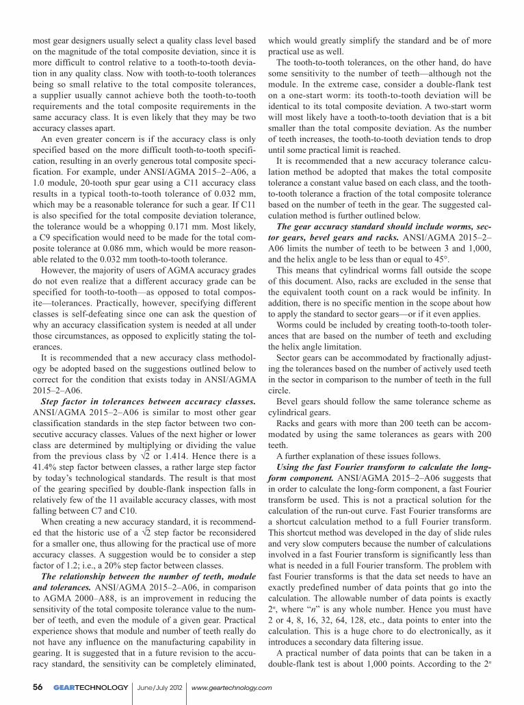
most gear designers usually select a quality class level based on the magnitude of the total composite deviation, since it is more difficult to control relative to a tooth-to-tooth devia-tion in any quality class. Now with tooth-to-tooth tolerances being so small relative to the total composite tolerances, a supplier usually cannot achieve both the tooth-to-tooth requirements and the total composite requirements in the same accuracy class. It is even likely that they may be two accuracy classes apart.
An even greater concern is if the accuracy class is only specified based on the more difficult tooth-to-tooth specifi-cation, resulting in an overly generous total composite speci-fication. For example, under ANSI/AGMA 2015–2–A06, a 1.0 module, 20-tooth spur gear using a C11 accuracy class results in a typical tooth-to-tooth tolerance of 0.032 mm, which may be a reasonable tolerance for such a gear. If C11 is also specified for the total composite deviation tolerance, the tolerance would be a whopping 0.171 mm. Most likely, a C9 specification would need to be made for the total com-posite tolerance at 0.086 mm, which would be more reason-able related to the 0.032 mm tooth-to-tooth tolerance.
However, the majority of users of AGMA accuracy grades do not even realize that a different accuracy grade can be specified for tooth-to-tooth—as opposed to total compos-ite—tolerances. Practically, however, specifying different classes is self-defeating since one can ask the question of why an accuracy classification system is needed at all under those circumstances, as opposed to explicitly stating the tol-erances.
It is recommended that a new accuracy class methodol-ogy be adopted based on the suggestions outlined below to correct for the condition that exists today in ANSI/AGMA 2015–2–A06.
Step factor in tolerances between accuracy classes. ANSI/AGMA 2015–2–A06 is similar to most other gear classification standards in the step factor between two con-secutive accuracy classes. Values of the next higher or lower class are determined by multiplying or dividing the value from the previous class by √2 or 1.414. Hence there is a 41.4% step factor between classes, a rather large step factor by today’s technological standards. The result is that most of the gearing specified by double-flank inspection falls in relatively few of the 11 available accuracy classes, with most falling between C7 and C10.
When creating a new accuracy standard, it is recommend-ed that the historic use of a √2 step factor be reconsidered for a smaller one, thus allowing for the practical use of more accuracy classes. A suggestion would be to consider a step factor of 1.2; i.e., a 20% step factor between classes.
The relationship between the number of teeth, module and tolerances. ANSI/AGMA 2015–2–A06, in comparison to AGMA 2000–A88, is an improvement in reducing the sensitivity of the total composite tolerance value to the num-ber of teeth, and even the module of a given gear. Practical experience shows that module and number of teeth really do not have any influence on the manufacturing capability in gearing. It is suggested that in a future revision to the accu-racy standard, the sensitivity can be completely eliminated,
which would greatly simplify the standard and be of more practical use as well.
The tooth-to-tooth tolerances, on the other hand, do have some sensitivity to the number of teeth—although not the module. In the extreme case, consider a double-flank test on a one-start worm: its tooth-to-tooth deviation will be identical to its total composite deviation. A two-start worm will most likely have a tooth-to-tooth deviation that is a bit smaller than the total composite deviation. As the number of teeth increases, the tooth-to-tooth deviation tends to drop until some practical limit is reached.
It is recommended that a new accuracy tolerance calcu-lation method be adopted that makes the total composite tolerance a constant value based on each class, and the tooth-to-tooth tolerance a fraction of the total composite tolerance based on the number of teeth in the gear. The suggested cal-culation method is further outlined below.
The gear accuracy standard should include worms, sec-tor gears, bevel gears and racks. ANSI/AGMA 2015–2–A06 limits the number of teeth to be between 3 and 1,000, and the helix angle to be less than or equal to 45°.
This means that cylindrical worms fall outside the scope of this document. Also, racks are excluded in the sense that the equivalent tooth count on a rack would be infinity. In addition, there is no specific mention in the scope about how to apply the standard to sector gears—or if it even applies.
Worms could be included by creating tooth-to-tooth toler-ances that are based on the number of teeth and excluding the helix angle limitation.
Sector gears can be accommodated by fractionally adjust-ing the tolerances based on the number of actively used teeth in the sector in comparison to the number of teeth in the full circle.
Bevel gears should follow the same tolerance scheme as cylindrical gears.
Racks and gears with more than 200 teeth can be accom-modated by using the same tolerances as gears with 200 teeth.
A further explanation of these issues follows.Using the fast Fourier transform to calculate the long-
form component. ANSI/AGMA 2015–2–A06 suggests that in order to calculate the long-form component, a fast Fourier transform be used. This is not a practical solution for the calculation of the run-out curve. Fast Fourier transforms are a shortcut calculation method to a full Fourier transform. This shortcut method was developed in the day of slide rules and very slow computers because the number of calculations involved in a fast Fourier transform is significantly less than what is needed in a full Fourier transform. The problem with fast Fourier transforms is that the data set needs to have an exactly predefined number of data points that go into the calculation. The allowable number of data points is exactly 2n, where “n” is any whole number. Hence you must have 2 or 4, 8, 16, 32, 64, 128, etc., data points to enter into the calculation. This is a huge chore to do electronically, as it introduces a secondary data filtering issue.
A practical number of data points that can be taken in a double-flank test is about 1,000 points. According to the 2n
GEARTECHNOLOGY June/July 2012 www.geartechnology.com56
theory, one would need exactly 512 data points, or possibly 1,024 data points. If the apparatus can precisely measure only 512 or 1,024 data points—for whatever reason—which is usually the case due to computer timing issues—then one needs to either first discard data points or add data points by some other mathematical filtering algorithm. By discarding the wrong points one could alter the tooth-to-tooth results, creating more inaccuracy. Given our fast computers of today, the solution is to use a full Fourier transform using the full data set, and one does not need to deal with the problems of data selection at all.
In any future standard, since it is not recommended that the long-form component be used for the determination of the quality of a gear, the use of a full Fourier transform may seem to be a moot point. However, it is very useful if a designer wishes to establish an “approximate” run-out speci-fication or if the measurement of “approximate” run-out is a benefit for process control.
Exclusion of manual gaging with ANSI/AGMA 2015–2–A06. Due to the sophisticated calculating methods required for tooth-to-tooth results, the proper implementation of ANSI/AGMA 2015–2–A06 makes all non-computerized (manual) double-flank testers incapable of providing a mea-surement result. These types of testers—even today—remain the most frequently used testers in the industry. The standard should not ignore what is happening in industry and the use of these testers. Any future standards must include the provi-sion to use indicator-type testers.
Test pressure. Currently, AGMA 915–3–A05 makes rec-ommendations for test pressure based on the gear’s mod-ule and face width, along with an adjustment if the gear is made of plastic instead of metal. A new standard should include the definition of a double-flank test pressure as, in some cases, test pressure may influence results. However, the information sheet should provide more detail on how to establish an appropriate test pressure based on the specific tester’s natural response, and based on the geometry, mate-rial and structure of the gear being tested. A simple table—as currently exists in AGMA 915–2–A05—is not sensitive to all of these issues.
Numbering for accuracy grades can be confusing. One of the biggest sources of confusion in specifying the accu-racy class is when only the numerical grade is used, without reference to whether it is a Q designation—as covered by AGMA 2000–A88—or a C designation—as covered by ANSI/AGMA 2015–2–A06. ANSI/AGMA 2015–2–A06 uses an accuracy class designation from C4 to C12, with C4 being the most accurate grade, where AGMA 2000–A88 uses classes Q3 to Q15, with Q15 being the most accurate grade. The reverse in the numbering brings the AGMA classes more in line with other standards. Those who specify gears using AGMA accuracy grades need to take greater care when specifying just a class number on their drawings; simply stating AGMA 8 would be quite misleading, as it would not be clear if it is a Q8 or a C8—two entirely different things. The overlap in numbering is unfortunate; any future system should consider an entirely different set of numbers to avoid further confusion.
Proposal for a Revised Radial Gear Accuracy Classification System
Based on the discussion above, the following recommen-dations are made for a revised AGMA radial gear accuracy classification system:• Return to the AGMA 2000–A88 definition of the tooth-to-
tooth deviation as being the difference in the tight-mesh center-distance within a single-tooth zone without adjust-ment for the long-form component. This simplifies the issue and allows for use of either electronic or manual gages.
• Include in the scope the use of the system for cylindrical worms, worm gears, sector gears, racks and bevel gears. For racks, use 200 teeth in the calculation of tooth-to-tooth tolerances. For gears with more than 200 teeth, default to 200 teeth for calculation purposes. For sector gears, in the calculation of total composite and tooth-to-tooth tolerance, adjust the full-circle value by the fraction of the number of teeth in the sector compared to the number of teeth full-circle.
• Create accuracy grades R20–R30 (R for radial) that are based on a constant value for total composite tolerance, with an associated tooth-to-tooth value that varies with the number of teeth. Adjust the tooth-to-tooth tolerance to be more practical in relation to the total composite tolerance. The class value 20–30 is used to avoid numerical duplica-tion with any other system.
• Reduce the step size between classes to 20%.• Recommend a way to calculate “approximate run-out”
from the double-flank charts in case people can benefit from this information for part development purposes. This can be based on using a full Fourier transform to calculate the long-form component only in cases where an optional run-out requirement is explicitly stated on the drawing—not necessarily for everyday use, but as a way to assist in calculation of other gear geometry.
• Recommend a method of determining the ideal test pres-sure based on the natural response of the tester and the test piece characteristics, using the least pressure stable read-ing approach. The test pressure needs to be documented and held consistent for all measurements of the same part number.The formulas for the calculation of the tolerances are rec-
ommended as follows:For the radial total composite tolerance: (1)
FidT = 1.2(R–26), mm10
whereR is the accuracy class
For the radial tooth-to-tooth tolerance: (2)FidT = 1.2(R–26–Log26z)
, mm10whereZ is the number of teeth in the full circle gear
For the “approximate” run-out tolerance: (3)FrT = (0.741) 1.2(R–26)
, mm10
www.geartechnology.com June/July 2012 GEARTECHNOLOGY 57
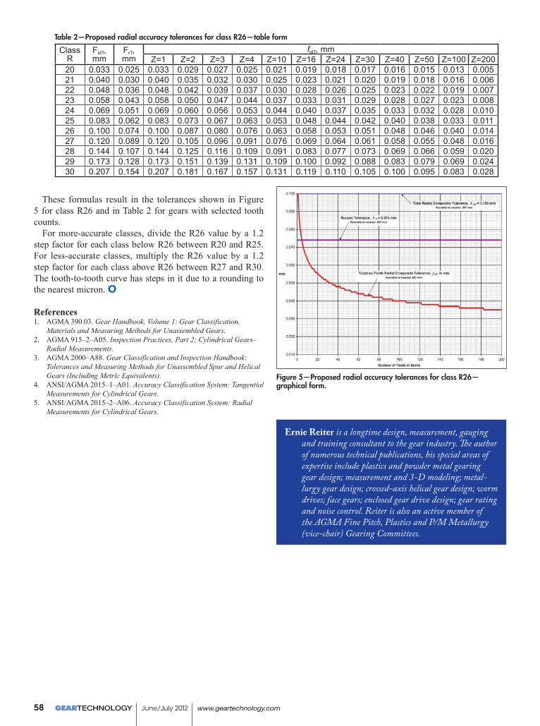
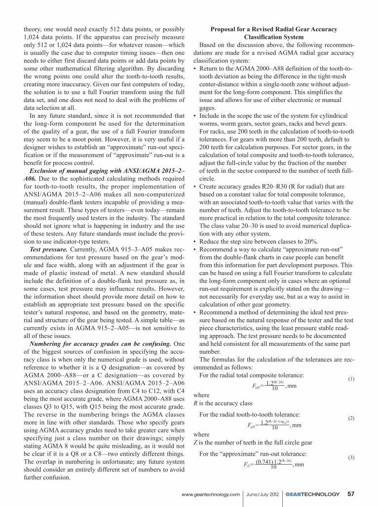
These formulas result in the tolerances shown in Figure 5 for class R26 and in Table 2 for gears with selected tooth counts.
For more-accurate classes, divide the R26 value by a 1.2 step factor for each class below R26 between R20 and R25. For less-accurate classes, multiply the R26 value by a 1.2 step factor for each class above R26 between R27 and R30. The tooth-to-tooth curve has steps in it due to a rounding to the nearest micron.
References1. AGMA 390.03. Gear Handbook, Volume 1: Gear Classification,
Materials and Measuring Methods for Unassembled Gears.2. AGMA 915–2–A05. Inspection Practices, Part 2: Cylindrical Gears–
Radial Measurements.3. AGMA 2000–A88. Gear Classification and Inspection Handbook:
Tolerances and Measuring Methods for Unassembled Spur and Helical Gears (Including Metric Equivalents).
4. ANSI/AGMA 2015–1–A01. Accuracy Classification System: Tangential Measurements for Cylindrical Gears.
5. ANSI/AGMA 2015–2–A06. Accuracy Classification System: Radial Measurements for Cylindrical Gears.
Figure 5—Proposed radial accuracy tolerances for class R26—graphical form.
Table 2—Proposed radial accuracy tolerances for class R26—table form
ClassR
FidT,mm
FrT,mm
fidT, mmZ=1 Z=2 Z=3 Z=4 Z=10 Z=16 Z=24 Z=30 Z=40 Z=50 Z=100 Z=200
20 0.033 0.025 0.033 0.029 0.027 0.025 0.021 0.019 0.018 0.017 0.016 0.015 0.013 0.00521 0.040 0.030 0.040 0.035 0.032 0.030 0.025 0.023 0.021 0.020 0.019 0.018 0.016 0.00622 0.048 0.036 0.048 0.042 0.039 0.037 0.030 0.028 0.026 0.025 0.023 0.022 0.019 0.00723 0.058 0.043 0.058 0.050 0.047 0.044 0.037 0.033 0.031 0.029 0.028 0.027 0.023 0.00824 0.069 0.051 0.069 0.060 0.056 0.053 0.044 0.040 0.037 0.035 0.033 0.032 0.028 0.01025 0.083 0.062 0.083 0.073 0.067 0.063 0.053 0.048 0.044 0.042 0.040 0.038 0.033 0.01126 0.100 0.074 0.100 0.087 0.080 0.076 0.063 0.058 0.053 0.051 0.048 0.046 0.040 0.01427 0.120 0.089 0.120 0.105 0.096 0.091 0.076 0.069 0.064 0.061 0.058 0.055 0.048 0.01628 0.144 0.107 0.144 0.125 0.116 0.109 0.091 0.083 0.077 0.073 0.069 0.066 0.059 0.02029 0.173 0.128 0.173 0.151 0.139 0.131 0.109 0.100 0.092 0.088 0.083 0.079 0.069 0.02430 0.207 0.154 0.207 0.181 0.167 0.157 0.131 0.119 0.110 0.105 0.100 0.095 0.083 0.028
Ernie Reiter is a longtime design, measurement, gauging and training consultant to the gear industry. The author of numerous technical publications, his special areas of expertise include plastics and powder metal gearing gear design; measurement and 3-D modeling; metal-lurgy gear design; crossed-axis helical gear design; worm drives; face gears; enclosed gear drive design; gear rating and noise control. Reiter is also an active member of the AGMA Fine Pitch, Plastics and P/M Metallurgy (vice-chair) Gearing Committees.
GEARTECHNOLOGY June/July 2012 www.geartechnology.com58