
Towards a Non-linear Full Aircraft Model for Large ... · PDF file• Geometrically exact...
18
Towards a Non-linear Full Aircraft Model for Large Passenger Aircraft Loads Calculations Javon Farao 1 Prof Arnaud G. Malan 1 Francesco Gambioli 2 1 UCT Industrial Computational Fluid Dynamics Research Group 2 AIRBUS – ‘Loads and Aeroelastics’ Department IFASD Conference 2017 June 2017
Transcript of Towards a Non-linear Full Aircraft Model for Large ... · PDF file• Geometrically exact...
Towards a Non-linear Full Aircraft
Model for Large Passenger Aircraft
Loads CalculationsJavon Farao1
Prof Arnaud G. Malan1
Francesco Gambioli2
1UCT Industrial Computational Fluid Dynamics Research Group2AIRBUS – ‘Loads and Aeroelastics’ Department
IFASD Conference 2017June 2017
Full Aircraft Model
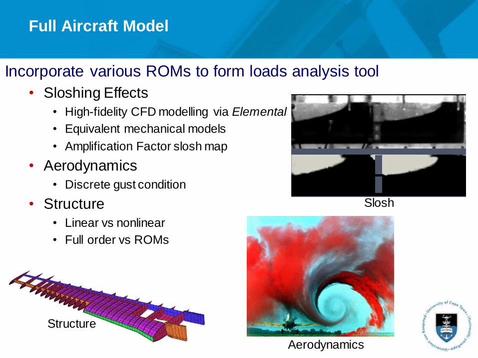
Incorporate various ROMs to form loads analysis tool
• Sloshing Effects
• High-fidelity CFD modelling via Elemental
• Equivalent mechanical models
• Amplification Factor slosh map
• Aerodynamics
• Discrete gust condition
• Structure
• Linear vs nonlinear
• Full order vs ROMs
Structure
Aerodynamics
Slosh
Various approaches to geometrically nonlinear beam structure
• Non-linear finite element analysis
• Updated/total Lagrangian formulation
• Computationally expensive approach
• Intrinsic beam
• Velocity and strains employed as degrees-of-freedom
• Co-rotational formulation
• Geometrically exact nonlinear beam
• Quadratic mode shape analysis
• Pragmatic approach to include quadratic nonlinearities
Brief Background
Quadratic Mode Shape Analysis
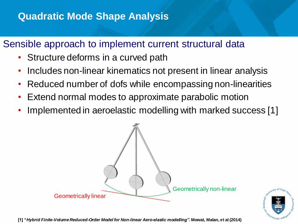
Sensible approach to implement current structural data
• Structure deforms in a curved path
• Includes non-linear kinematics not present in linear analysis
• Reduced number of dofs while encompassing non-linearities
• Extend normal modes to approximate parabolic motion
• Implemented in aeroelastic modelling with marked success [1]
Geometrically linear
Geometrically non-linear
[1] “Hybrid Finite-Volume Reduced-Order Model for Non-linear Aero-elastic modelling”. Mowat, Malan, et al (2014)

Structural Reduced Order Model (ROM)
Finite element structure to equivalent beam
• Static condensation
• Produce stiffness matrix
• Produce element properties
Modal analysis
• Large, sparse matrices
Temporal solution
• Newmark method
Quadratic mode shape [2]
[2] “A Method for Calculating the Dynamics of Rotating Flexible Structures, Part 1: Derivation”. Segalmann, Dohrmann (1995)
FEM Structure
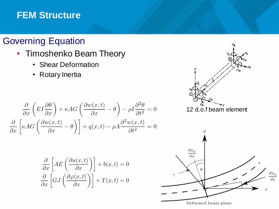
Governing Equation
• Timoshenko Beam Theory
• Shear Deformation
• Rotary Inertia
12 d.o.f beam element

Modal Analysis
Large, sparse matrices
• Aircraft wing experiences excitation in lowest frequency modes
• Compute primary frequencies and associated modes
Solve generalised eigen-problem
Cholesky Factorization of mass matrix
• Simplify to standard eigen-problem
Modal Analysis
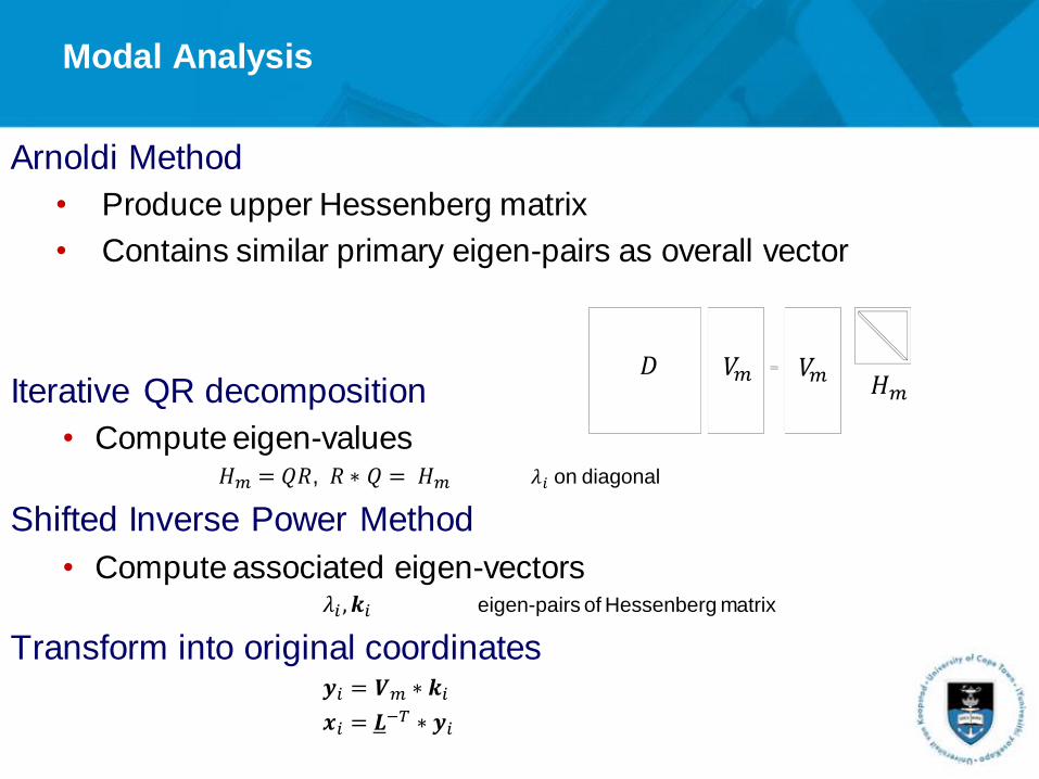
Arnoldi Method
• Produce upper Hessenberg matrix
• Contains similar primary eigen-pairs as overall vector
Iterative QR decomposition
• Compute eigen-values𝐻𝑚 = 𝑄𝑅, 𝑅 ∗ 𝑄 = 𝐻𝑚 𝜆𝑖 on diagonal
Shifted Inverse Power Method
• Compute associated eigen-vectors𝜆𝑖 , 𝒌𝑖 eigen-pairs of Hessenberg matrix
Transform into original coordinates𝒚𝑖 = 𝑽𝑚 ∗ 𝒌𝑖
𝒙𝑖 = 𝑳−𝑇 ∗ 𝒚𝑖
𝑉𝑚 𝑉𝑚 𝐻𝑚𝐷
Quadratic Mode Shape Analysis
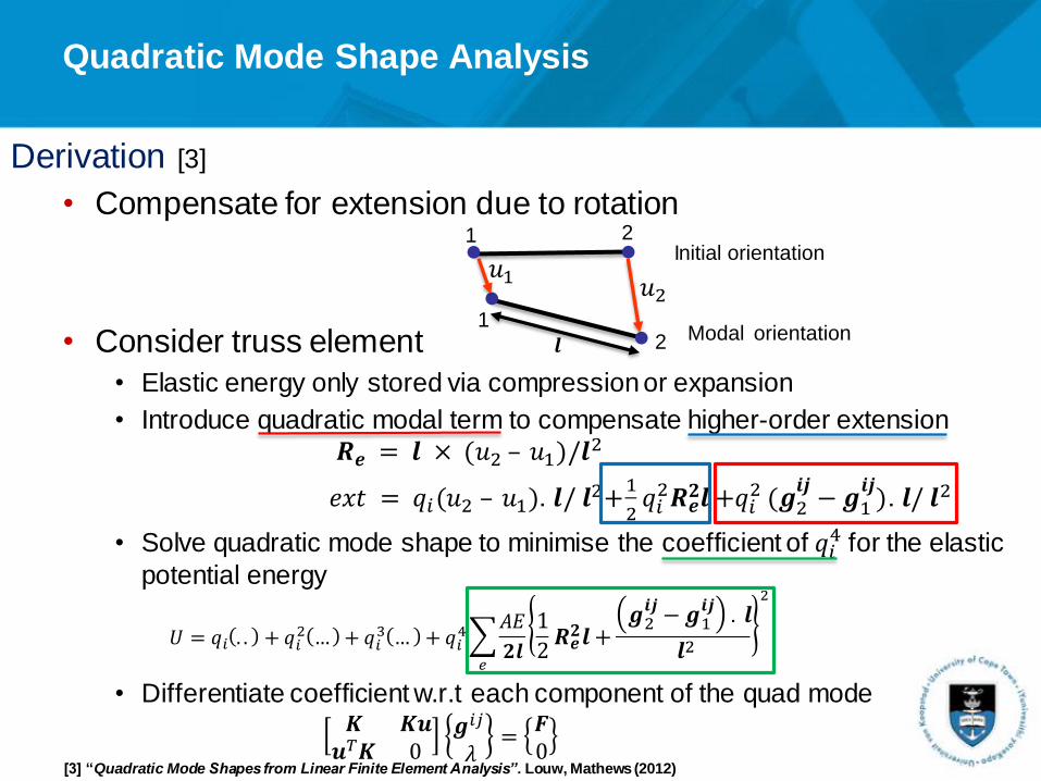
Derivation [3]
• Compensate for extension due to rotation
• Consider truss element
• Elastic energy only stored via compression or expansion
• Introduce quadratic modal term to compensate higher-order extension
𝑹𝒆 = 𝒍 × (𝑢2 – 𝑢1)/𝒍2
𝑒𝑥𝑡 = 𝑞𝑖(𝑢2 – 𝑢1). 𝒍/ 𝒍2+1
2𝑞𝑖2𝑹𝒆𝟐𝒍 +𝑞𝑖
2 (𝒈2𝒊𝒋−𝒈1𝒊𝒋). 𝒍/ 𝒍2
• Solve quadratic mode shape to minimise the coefficient of 𝑞𝑖4 for the elastic
potential energy
𝑈 = 𝑞𝑖 . . + 𝑞𝑖2 … + 𝑞𝑖
3 … + 𝑞𝑖4
𝑒
𝐴𝐸
𝟐𝒍
1
2𝑹𝒆𝟐𝒍 +𝒈2𝒊𝒋−𝒈1𝒊𝒋
. 𝒍
𝒍2
2
• Differentiate coefficient w.r.t each component of the quad mode𝑲 𝑲𝒖𝒖𝑇𝑲 0
𝒈𝑖𝑗
𝜆=𝑭0
[3] “Quadratic Mode Shapes from Linear Finite Element Analysis”. Louw, Mathews (2012)
1 2Initial orientation
12 Modal orientation
𝑢2𝑢1
𝒍
Verification and Validation
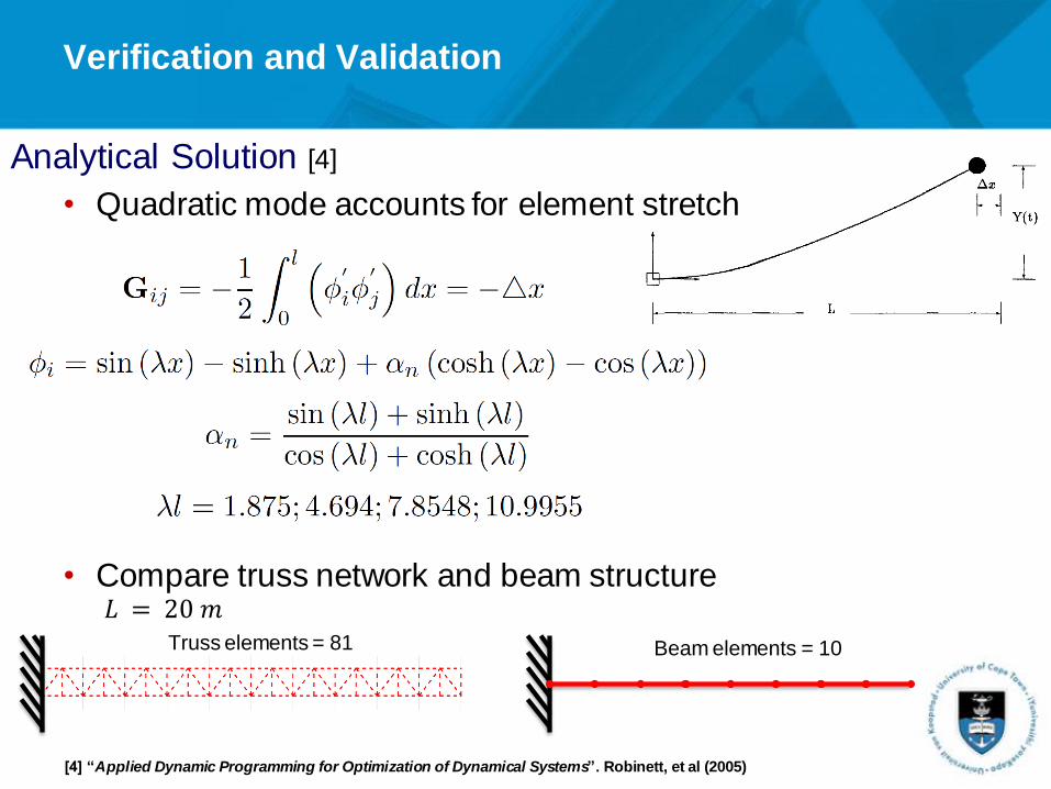
Analytical Solution [4]
• Quadratic mode accounts for element stretch
• Compare truss network and beam structure
[4] “Applied Dynamic Programming for Optimization of Dynamical Systems”. Robinett, et al (2005)
𝐿 = 20 𝑚Truss elements = 81 Beam elements = 10

Verification and Validation
Analytical comparison
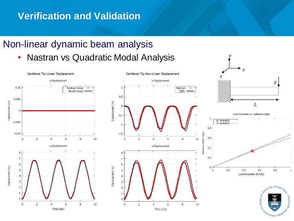
Verification and Validation
Non-linear dynamic beam analysis
• Nastran vs Quadratic Modal Analysis
𝐹
𝐿
𝑥
𝑦
𝑧

Verification and Validation
Geometrically non-linear beam inextensibility
Linear Cantilever Animation
Non-Linear Cantilever Animation – Quadratic Mode Shapes
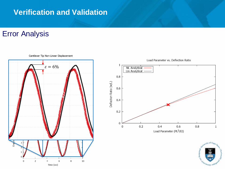
Error Analysis
Verification and Validation
𝜀 = 6%

Application to CRM wing
CRM wing FEM model condensed to beam elements [5]
Compare linear model to non-linear QMS approach• Half-gust load applied at wing tip to elicit large deformations
• 2% structural damping applied
[5] Condensation performed by Dr R. Cook from University of Bristol

Application to CRM wing
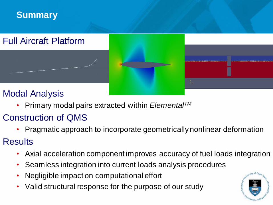
Full Aircraft Platform
Modal Analysis
• Primary modal pairs extracted within ElementalTM
Construction of QMS
• Pragmatic approach to incorporate geometrically nonlinear deformation
Results
• Axial acceleration component improves accuracy of fuel loads integration
• Seamless integration into current loads analysis procedures
• Negligible impact on computational effort
• Valid structural response for the purpose of our study
Summary

Acknowledgements
National Aerospace Centre
South African Research Chair Initiative
Airbus ‘Loads and Aeroelasticity’ Department – Bristol University of
Bristol – Dr R. Cook and Prof J. Cooper
Part of the research leading to this work has received funding from the European Union’s Horizon 2020 research and innovation programme under grant agreement number 636053.


![Vibration of Timoshenko Beam-Soil Foundation Interaction by …jsm.iau-arak.ac.ir/article_677316_9f91814aa7024a7daa258... · 2 days ago · span Timoshenko beam. Banerjee [15] investigated](https://static.fdocuments.in/doc/165x107/60c0f04fc2fd995b4c03c833/vibration-of-timoshenko-beam-soil-foundation-interaction-by-jsmiau-arakacirarticle6773169f91814aa7024a7daa258.jpg)

