Total Power Solutions - Eltek · Flatpack2 220VDC 48kW ... is the main building block in scalable...
44
Total Power Solutions Marine and Offshore
Transcript of Total Power Solutions - Eltek · Flatpack2 220VDC 48kW ... is the main building block in scalable...

Total Power SolutionsMarine and Offshore

Table of Contents
Marine powerfrom Eltek
Powering marine and offshore operations ..........................................................................4
Set course for lower cost of ownership ................................................................................6
Global power specialist: 40 years of experience ...............................................................8
The Rectiverter AC UPS - Marine power redefined .........................................................10
A case for reduced cost ........................................................................................................... 12
Meet an Eltek expert ..................................................................................................................14
Total Power Solutions: Application examples ...................................................................16
Converged power solutions /CPS/ ........................................................................................18
DC Systems
Flatpack2 220VDC 48kW..................................................................................................... 20
Flatpack2 24VDC 48kW ....................................................................................................... 22
Flatpack2 24VDC 8kW All in one ....................................................................................... 24
Flatpack S 24VDC 8kW ......................................................................................................... 26
Flatpack S 24VDC 8kW Wallbox ........................................................................................ 28
Flatpack S 24VDC 2kW Wallbox ........................................................................................ 30
Flatpack2 24-220VDC 4kW Wallbox................................................................................ 32
Flatpack S 24VDC 3kW Generator Starter .................................................................... 36
Flatpack2 110VDC 16kW ..................................................................................................... 38
AC Systems
Rectiverter UPS 115/230VAC 6kVA ................................................................................ 40
Inverter system 230VAC 10KVA ........................................................................................ 42
Modular Inverter & Charger 400/230VAC 30kVA & 60kVA ..................................... 44
Powershelves
Flatpack2 19” 2U ................................................................................................................... 46
Flatpack S 19” 3U ................................................................................................................... 48
Flatpack S 19” 1U .................................................................................................................... 50
Flatpack S Stand-Alone ........................................................................................................ 54
Flatpack S Portable Emergency Unit .............................................................................. 56
Power Modules
Flatpack2 Rectifier................................................................................................................. 58
Flatpack S Rectificer ............................................................................................................. 62
Micropack Rectifier ................................................................................................................ 64
Cliq M DIN-Rail Power Supply .............................................................................................. 68
Rectiverter 48V 230/1500 48/1200 & 115/750 48/600 ....................................... 70
Bravo Inverter 2500VA 220VDC/230VAC ...................................................................... 72
Controllers and monitoring
Smartpack 2 ..............................................................................................................................74
Smartpack S ............................................................................................................................. 76
Compack .................................................................................................................................... 80
Battery cabinets and batteries
Battery Cabinets ..................................................................................................................... 82
Batteries .................................................................................................................................... 84

Powering marine and offshore operationsOur solutions are used within marine, oil and gas and wind farms. They power supervision, automation, data transmission, switchgear control, safety, emergency systems, dynamic positioning and ballast water treatment.

An Eltek Modular UPS, designed and certified for marine use, is the secure and safe way to improve the efficiency and flexibility of onboard power supplies. It will significantly reduce complexity, increase control and manageability, and provide the basis for a future-proof on board power infrastructure.
The bottom line is a significant reduction in total cost of ownership.
Set course for lower cost of ownership
6 7

Eltek Offices
• Installation• Start-up and commissioning• Preventive maintenance• 24/7 emergency service• Product repairs• Training• Battery testing• Extended warranty
Wide range of servicesOur solutions are supplemented by a wide range of services:
• Scalable – expand as your load grows or add redundancy• Serviceable – module replacement in seconds• Designed to last – design life of 15 years• Flexible – for all AC and DC needs• Compact – save space• Reliable – high MTBF
Modular, high-quality & future-proof power solutionsBased on switch-mode technology, our high quality solutions are:
Global power specialist40 years of experience
Eltek is part of the proud Norwegian maritime and offshore heritage and can look back on more than 40 years experience as a dedicated power specialist, developing modular, compact and reliable solutions for use in demanding environments.
Eltek AS @Eltekcorp @EltekCorp Eltek AS
8 9

Generator
Batteries
Load
AC
DCLoad
The Rectiverter AC UPS - marine power redefinedThe Rectiverter is a unique concept in power conversion. First and foremost, it is a very efficient and compact AC UPS for marine applications.
In addition, it combines the functionality of a rectifier, an inverter and a static transfer switch in one bidirectional power module. This opens up a new power flow architecture and a new way of designing power systems, meeting the needs for both AC and DC output in one modular system.
Visit rectiverter.com
1110

18 kVA Rectiverter building block6 kVA Rectiverter building block
The advantages of a modular systems are significant, when it comes to scalability, reliability and overall quality. In turn, this adds up to significant reductions in total cost of ownership over the system’s life time.
A case for reduced cost A Rectiverter system fits into applications where commercial, monoblock UPS systems are used. Although monoblock solutions are modified to meet strict marine requirements, they are not designed to meet them, and consequently display relatively high fault rates and represent a very high service cost compared to the cost of the equipment.
By installing Rectiverter UPS systems, designed for use on ships and offshore installations, and with components designed for a significantly longer lifetime, system fault rates will be significantly reduced. Add improved serviceability to the equation, and the reduction in service cost alone will cover the additional investment in equipment several times.
Despite a somewhat higher initial cost, the advantages of the Rectiverter UPS add up to significant savings:
Up to 80 % reduced life time cost.
With the same dimensions and mechanical design as Eltek's other modules, the Rectiverter is the main building block in scalable systems for a wide range of marine applications.
A Rectiverter UPS system multiplies the advantages of a modular power architecture
Up to 80 %reduced lifetime cost
Hot swap modules
Marine Rectiverter UPS 6 kVA * example on UPS, see page 40
1312

A vessel or offshore installation is a complex environmentThere may be dozens – if not hundreds – of functions and equipment and systems on board, from absolutely essential navigation and propulsion systems with backup power, to convenient ”nice-to-haves”, like onboard entertainment systems. Every one of these requires power, some AC and some DC, at different voltages, with or without backup. Typically, there are many different makes, from different suppliers, and with varying product life time expectations.
Complexity is expensiveIt is obvious that complexity comes at a cost. It may be hard to see the full picture and be on top of things. There are many potential points of failure, and the cost of service or repair due to poor quality or short life expectancy may, in many cases, exceed the initial purchase cost.
Modularity is the keyThere is an obvious case to be made for simplification. Fewer components and less equipment, the ability to oversee and manage several subsystems as one, shared backup batteries and one common management interface – these are things that will yield substantial benefits in terms of reliability and operational cost.
This is exactly what a modular approach will provide. With just a few standard components, any size and form of system can easily be configured and set up – and be scaled up, or down - according to needs. A modular approach will make stand-alone, monoblock
UPS systems and other power equipment obsolete.
Where Eltek fits in Eltek has decades of experience with modular power systems, and an equally long history as a supplier to the marine market. We have a wide range of products and solutions specifically developed or adapted for marine use, all with DNV and ABS certification. This enables us to provide the required power for most purposes.
There is more in it for customersThe benefits of adopting modularity go beyond those directly associated with the products and technology – including performance, compact form factor, flexibility and overall quality. By reducing the number of suppliers, life becomes easier. There will be less time and cost spent on surveys and approvals, and a reduction of the spare parts stock. In the rare event of a malfunctioning module, a new one can be easily hot-swapped without interfering with the running system. This also opens up the possibility for ”smart logistics” – i.e. installing the modules and finalizing the system setup when the environmental conditions are favorable.
An additional – and important – benefit is that a customer can deal with the same company, no matter where in the world his ships are sailing. An Eltek representative and spare parts, assistance or additional products that may be required are never far away.
One step further with the Rectiverter AC UPSThe benefits really add up. We are confident that customers who embrace the modular approach will significantly reduce operating and maintenance cost, improved reliability and greater flexibility.
These benefits are further strengthened with the Rectiverter – the modular AC UPS. With its modularity, efficiency and dual output, it is the perfect building block for tomorrow’s marine and offshore power solutions.
Meet an Eltek expertName Ingar Sørensen
Position Global Director Marine & Offshore
Location Norway
Contact [email protected] Drawing on many years of experience from the power conversion field in general, and the marine and offshore sectors in particular, Ingar Sørensen knows where marine power is heading.
“Higher performance at a lower total cost of ownership’’Marine power expert Ingar Sørensen expands on the benefits of modern modular power in marine environments.
Meet Ingar Sørensen in this 2 minutes documentary
Scan the QR code or go to: www.eltek.com/marine
14 15

12
3
4
5
89
10
11
6
7
• Dynamic positioning
• Propulsion control
• Water tight doors
• Navigation
• Ship identification
• Ballast water treatment
• Drilling systems
• Data center
• Cranes
• Public address and alarm
• AC Substations
• Automation
Total Power SolutionsApplication examples
Continuous and safe operation of critical and auxiliary on-board systems and equipment begins and ends with stable and safe supply of AC and DC power. Our power solutions are of the highest quality, developed and certified for marine and offshore use.
Their scalability, compactness and efficiency make them ideal for most applications, including:
THE ILLUSTRATION SHOWS EXAMPLES OF APPLICATIONS AND SYSTEMS ON A VESSEL:
3
2
1
4 8
7
5
6
11
9
10
Control/automation DC UPS
GMDSS & PA
Bridge power conversion
Navigation & DP UPS
Emergency Lighting System
Generator starter UPS
SAS DC UPS
Propulsion DC UPS
Engine starter UPS
Engine room DC UPS
Thruster DC UPS
16 17

Eltek Central Power System/CPS/
CPS is a high-end solution for ships and oil installations. In most cases, central power systems replace the AC-UPS and provide a closed and high-voltage DC bus that can convert to various voltages with a central battery back-up.
• Modular/scalable• Fewer and global spares• One management system• Easily serviceable (short MTTR)• Real battery management• Fewer battery banks
• Full redundancy (all levels)• Easy installation • Standard solutions with DNV and ABS approval• Low life time cost
CENTRALIZED POWER A
CENTRALIZED POWER B
220VDC
220VDC
MAINS NO 1
MAINS NO 2
EMERGENCY
EMERGENCY
24VDC12VDC 48VDC 60VDC 110VDC 220VDC 230VAC 380VDC
18 19

CENTRAL POWER SYSTEM (CPS)
Flatpack2 220VDC 48kW
Traditional UPS solutions have a DC to AC conversion step between the batteries holding the backup energy and the load distribution. A fault in this converter step will cause the connected equipment to go down.
The Flatpack2 220V/48kW system distributes 220V DC directly from the batteries and rectifiers. The system has 2 battery breakers supporting 2 external strings. The result is battery string and breaker redundancy, strengthening the reliability of the system.
Two output breakers allows for 2 redundant distribution branches that can feed equipment with dual feed input or redundant DC/DC converters.
Compared to traditional UPS, the removal of the DC to AC step contributes to increased end to end efficiency of the system. Combined with less energy wasted on cooling the power equipment and batteries, a significant operational cost reduction is achieved.
220VDC – A MORE RELIABLE UPS SOLUTION
220VDC – A MORE EFFICIENT UPS SOLUTION
KEY FEATURES• DNV / ABS approved
(pending)
• Scalable
• Hot swappable modular rectifier units
• High efficiency
• Digital controllers
• Heat management
• Unique connection
• Ingress protection up to IP43
APPLICATIONS• Offshore
• Ships
• Part of the Eltek Central Power System
The combination of high voltage for cost effective distribution and DC directly from redundant battery strings and redundant rectifiers, makes this system ideal for powering critical equipment in ships, larger buildings and factories.
The highly efficient Flatpack2 220V/2000W HE rectifiers makes sure that 95% of supplied energy from mains or generators are fed into the load and batteries. This allows huge savings in operational cost, and it can also have a significant environmental impact.
Eltek — Gråterudveien 8, PB 2340 Strømsø, 3003 Drammen, Norway Phone: +47 32 20 32 00 Eltek © 2016 – www.eltek.com
MODEL FLATPACK 2 220VDC 48 KW
Part number C22438.400
INPUT DATA
Connection 2 x 3phase + PE terminals. Tension clamp (2.5 – 35mm2)
Voltage (phase to phase) 230Vac (∆) nominal
Maximum current 100 ARMS per phase (at full load)
Input protection 3 Pole 100A MCCB, SPD
Input protection in each rectifier Varistors for transient protection, mains fuse in both lines, disconnect above 300 V
OUTPUT DATA
VoltageAdjustable
Default: 245.3 VDC (without controller)Range: 178.5 – 297 VDC (220 – 297 VDC with no load)
Pb (NiCd) Batteries 108-120 (170 – 180) cells
Output current 220 Amps at Vout ≤ 220 VDC and within nominal input
Output power 48 kW maximum within nominal input
Output protection in rectifiers Overvoltage shutdown, OR-ing diode
Battery protection/Load protection 2 x 250A MCCB / 2 x 250A, M8 cable lug
CONTROL AND MONITORING
Controller Smartpack 2
Digital inputs 6 (Aux Sw: NO/NC)
Temperature 3 inputs (NTC probes) (optional)
Relay outputs 6 (Switching capacity max 2A/75V/60W)
Customer Connections Tension clamp (0.5 – 1.5mm2)
ALL MODELS
OTHER SPECIFICATIONS Efficiency 95%
Temperature
Operating: -40 to +45°C (-40 to +113°F)Storage: -40 to +85°C (-40 to +185°F)
Isolation 3.0 KVAC – input to output, 1.5 KVAC – input and output to earth
Dimensions (H x D) 1800 (+100)x 800 x 600 mm (WxDxH) (70.9 x 34.5 x 23.6’’)
Weight Net weight: 306 kg, Gross weight: 341 kg
IP grade specification IP43, Vibration absorbers are optional
DESIGN STANDARDS Electrical safety IEC 60950-1 IEC 60945
EMC ETSI EN 300 386 V.1.3.3, EN 61000-6, -1, -2, -3, -4
Environment ETSI EN 300 019-2,-1 Class 1.2, -2 Class 2.3, -3 Class 3.2, RoHS
Marine ABS (PENDING)DNV-OS-D202, Ch.2 Sec. 4 (DNV 2.4)o Temperature Cl. Ao Vibration Cl. Ao Humidity Cl. Ao Enclosure Cl. A
ORDERING INFORMATION
C22438.400 FP2 220V 48kW 2x3PH230VAC CPS
241115.815M Rectifier Flatpack2 220/2000 HE WOR
BE0138.000 Battery cabinet CPS 4sh 38U
Doc C22438.400.DS3 – rev1 Specifications are subject to change without notice
DC Systems Errors and O
missions Excepted
20 21

CENTRAL POWER SYSTEM (CPS)
Flatpack2 24VDC 48kW
The Flatpack2 24V 48kW has been specifically designed to meet the demand for higher density and more compact power solutions for marine applications worldwide. It is suitable for applications needing an expandable, easily serviceable and reliable power supply, fitting within a minimal space.
The modular concept of the Flatpack2 systems makes it easy to scale the Flatpack2 24V/48kW to fit specific power needs from 4 to 48kW. A system with unused rectifier positions can be expanded later simply by adding more rectifiers.
The power system is monitored by Smartpack 2 controller which has all the functionality required for present and future applications.
It contains 6U of PRs (power rack) which can house 24 Flatpack2 rectifier modules.
DESCRIPTIONKEY FEATURES• DNV / ABS approved
(pending)
• Scalable
• Hot swappable modular rectifier units
• High efficiency
• Digital controllers
• Heat management
• Unique connection
• Ingress protection up to IP43
APPLICATIONS• Offshore
• Ships
• Part of the Eltek Central Power System
The combination of cost-effective design, power density and reliability makes the Flatpack2 24V 48 kW a product family that truly stands out and provides unparalleled availability. The versatility of the Flatpack2 rectifier means that it can be used in a wide variety of 24 VDC marine applications across the globe.
Eltek — Gråterudveien 8, PB 2340 Strømsø, 3003 Drammen, Norway Phone: +47 32 20 32 00 Eltek © 2016 – www.eltek.com
MODEL FLATPACK 2 24VDC 48KWPart number C22438.401
INPUT DATA
Connection 2 x 3phase + PE terminalsNominal voltage 176VAC – 275VACMaximum current (1 Module included) Max. 13 Arms at 176Vrms input and full load (9,8 Arms at 230V)Input protection 3 Pole 100A MCCBInput protection in each rectifier Varistors for transient protection, Mains fuse in both lines,
Disconnect above 300 VOUTPUT DATA
Maximum voltage 36 VDC
Output current (1 Module included) 84 Amps at 24 VDC and nominal inputOutput power 48 kW maximum within nominal inputOutput protection in rectifiers Overvoltage shutdown, OR-ing diode (241115.200M) Battery / Load protecti 2 x TPS 1200A / 2 x TPS 1200A
CONTROL AND MONITORINGController Smartpack 2Digital inputs 6 (Aux Sw: NO/NC)Temperature 3 inputs (NTC probes) (optional)Relay outputs 6 (Switching capacity max 2A/75V/60W)Customer Connections Tension clamp (0.5 – 1.5mm2)
OTHER SPECIFICATIONSTemperature Operating: -40 to +45°C (-40 to +113°F)
Storage: -40 to +85°C (-40 to +185°F)Isolation 3.0 KVAC – input to output, 1.5 KVAC – input and output to earth
Dimensions (H x D)1800 x 800 x 600 mm (WxDxH) (70.9x34.5x23.6’’) with plinth 100mm
Weight Net weight: 306 kg, Gross weight: 341 kgIP grade specification IP43 outside cabinet, IP20 inside cabinet
DESIGN STANDARDSElectrical safety IEC 60950-1 IEC 60945EMC ETSI EN 300 386 V.1.3.3, EN 61000-6-1, -2, -3,-4, EN 61000-3-2Environment ETSI EN 300 019-2-1 Class 1.2, 2.3, 3.2, RoHS compliant
Marine ABS (Pending)DNV-OS-D202, Ch.2 Sec. 4 (DNV 2.4)o Temperature Cl. Ao Vibration Cl. Ao Humidity Cl. Ao Enclosure Cl. A
ORDERING INFORMATION
C22438.401 FP2 24V 48kW 2x3P220V
AVAILABLE 24V RECTIFIERS
Part Number Description Voltage Efficiency Maximum current OutputProtection
Range 1Module
6Module
12Module
24Module
241115.205M Flatpack 224V/1800W HE
21.7 – 28.8 V >95% (30-65% load)
75 A 450 A 900 A 1800 A Fuse
241115.200M Flatpack 2 24V/2000W
21 – 29 V >89% (25-100% load)
84 A 504 A 1008 A 2016 A Blocking diode
241115.250M Flatpack 224V/2000W WOR
21.5 – 36 V >91% (25-85% load)
70 A 420 A 840 A 1680 A Fuse
Doc C22438.401_DS_rev1
DC Systems Errors and O
missions Excepted
Specifications are subject to change without notice22 23

ALL IN ONE
Flatpack2 24VDC 8kW
The Flatpack2 24V 8kW has been specifically designed to meet the demand for higher density and more compact power solutions for the marine application worldwide. It is suitable for applications needing an expandable, easily serviceable and reliable power supply, fitting within a minimal space.
The modular concept of the Flatpack2 systems makes it easy to scale the Flatpack2 24V/48kW to fit specific power needs up to 8kW. A system with unused rectifier positions can be expanded later simply by adding more rectifiers.
The power system is monitored by Smartpack 2 controller which has all the functionality required for present and future applications.
It contains 2U of PRs (power rack) which can house 4 Flatpack2 rectifier modules, and a battery compartment.
DESCRIPTIONKEY FEATURES• DNV / ABS approved
(pending)
• Scalable
• Hot swappable modular rectifier units
• High efficiency
• Digital controllers
• Heat management
• Distribution section
• Battery compartment
APPLICATIONS• Control and protection
• SAS system
• Communication
• Emergency lighting
Based on the successful Flatpack2 rectifier module, this system can provide up to 8KW 24VDC with comprehensive distributions, terminations, and battery room, all housed in a 1,4m high cabinet.
Eltek — Gråterudveien 8, PB 2340 Strømsø, 3003 Drammen, Norway Phone: +47 32 20 32 00 Eltek © 2016 – www.eltek.com
MODEL FLATPACK 2 24VDC 8KW – ALL IN ONEPart number CIE20425.401
INPUT DATA
Connection 2 x 3phase + PE terminals with Automatic Transfer Switch Nominal voltage 176VAC – 275VAC
Maximum current (1 Module included) Max. 13 Arms at 176Vrms input and full load (9,8 Arms at 230V)Input protection Marine AC filter (no protection device)Input protection in each rectifier Varistors for transient protection,Mains fuse in both lines
Disconnect above 300 V
OUTPUT DATA
Maximum voltage 36 VDC
Output current (1 Module included) 84 Amps at 24 VDC and nominal inputOutput power 8 kW maximum within nominal inputOutput protection in rectifiers Overvoltage shutdown and fuse, OR-ing diode (241115.200M) Battery protectio 1 x C120H D125A 2P 15kA MCBLoad distribution 30 MCBs (1xB63A 2P, 14xB16A 2P, 15xB10A 2P, Ics=15kA)
CONTROL AND MONITORINGController Smartpack 2Digital inputs 6 (Aux Sw: NO/NC)Temperature 3 inputs (NTC probes) (optional)Relay outputs 6 (Switching capacity max 2A/75V/60W)Customer Connections Tension clamp (0.5 – 1.5mm2)
OTHER SPECIFICATIONSTemperature Operating: -40 to +45°C (-40 to +113°F)
Storage: -40 to +85°C (-40 to +185°F)Isolation 3.0 KVAC – input to output, 1.5 KVAC – input and output to earthDimensions (HxWxD) 1200 x 600 x 500 mm (47.2x23.6x19.6’’) with plinth+100mmBattery compartment dimensions (HxWxD) 4x(340mm x 110mm x 395mm)
Space for up to 4x100Ah VRLA battery Weight Net weight: 130 kg, Gross weight: 140 kg (without batteries)IP grade specification IP43 / IP44 outside cabinet, IP20 inside cabinet
DESIGN STANDARDSElectrical safety IEC 60950-1 IEC 60945EMC ETSI EN 300 386 V.1.3.3,EN 61000-6-1, -2, -3, -4, EN 61000-3-2Environment ETSI EN 300 019-2-1 Class 1.2, 2.3, 3.2, RoHS compliantMarine ABS (Pending)
DNV-OS-D202, Ch.2 Sec. 4 (DNV 2.4) (Rectifiers)o Temperature Cl. Ao Vibration Cl. Ao Humidity Cl. Ao Enclosure Cl. A
ORDERING INFORMATIONCIE20425.401 FP2 24V 8kW 2x2p230V BCE XP
AVAILABLE 24V RECTIFIERSPart Number Description Voltage Efficiency Maximum current Output
ProtectionRange 1Module
2Module
3Module
4Module
241115.205M Flatpack 2 24V/1800W HE
21.7 – 28.8 V >95% (30-65% load)
75 A 150 A 225 A 300 A Fuse
241115.200M Flatpack 2 24V/2000W 21 – 29 V >89% (25-100% load)
84 A 168 A 252 A 336 A Blocking diode
241115.250M Flatpack 2 24V/2000W WOR
21.5 – 36 V >91% (25-85% load)
70 A 140 A 210 A 280 A Fuse
Doc 22438.401.DS3 – rev1 Specifications are subject to change without notice
DC Systems Errors and O
missions Excepted
24 25

CENTRAL POWER SYSTEM (CPS)
Flatpack S 8kW 24VDC
The Flatpack S system is a 25U power system designed for use in 24VDC Marine applications. Marine filters are fitted on the input that makes this system meet the DNV requirement for marine applications. Flexible alarm and monitoring options are included in this modular design.
DESCRIPTIONKEY FEATURES• Powered from AC or DC
• Complete system
• Battery terminals
• Load distribution
• Hot pluggable rectifiers
• Hot pluggable controller
• Optional SIL 3 rectifiers
APPLICATIONS• Ships
• SAS systems
• Part of the Eltek Central Power System
The combination of cost-effective design, power density and reliability makes the Flatpack S 24V 8 kW a product family that truly stands out and provides unparalleled availability. The versatility of the Flatpack S rectifier means that it can be used in a wide variety of 24V DC marine applications across the globe.
Eltek — Gråterudveien 8, PB 2340 Strømsø, 3003 Drammen, Norway Phone: +47 32 20 32 00 Eltek © 2016 – www.eltek.com
MODEL FLATPACK S MARINE SYSTEM 8KW, 24VDC
Part number CS0825.000
INPUT DATA
Nominal voltage 185VAC/DC - 305VAC / 300VDC
Voltage range (DC) 85VAC/DC - 305VAC / 300VDC
Nominal current (at nominal input, full load) 37.6ARMS
Input connection 10 mm2 terminalsInput protection 2 x C32A 2 pole MCBMarine filters Optional
OUTPUT DATA
Nominal voltage 26.7 VDC
Voltage range 21.5 - 28VDC
Current 333.6A at 24VDC and full loadOutput power 8kW maximum (with 8 rectifiers)Load connection 20mm2 terminals. Load MCB: 6x6A 2p, 14x10A 2p, 8x16A 2p +AlarmProtection on each rectifier Blocking OR-ing FET, short circuit proof, high temperature protectionOvervoltage protection on SIL 3 rectifier Protection level: 30V, Proof test interval: 15 years, Handles dual
component failureBattery connection 70mm2
Alarm connection 2,5mm2
CONTROL AND MONITORINGSmartpack S 6 x Input/Output and EthernetAlarm connections Plug-in wire connectors rear access for 6 potential free relays 1.5mm2
OTHER SPECIFICATIONSIsolation 3.0 kVAC – input to output; 1.5 kVAC – input to earth
0.5 kVAC – output to earthOperating temperature -40 to +85°C (-40 to +185°F), humidity 5 - 95% RH non-
condensingStorage temperature -40 to +85°C (-40 to +185°F), humidity 0 - 99% RH non-
condensingDimensions 1200 x 600 x 600 mm (HxWxD) with plinth 100mmWeight Net weight: 131 kg, Gross weight 173 kg
DESIGN STANDARDSCabinet IP43 / 44EMC ETSI EN 300 386 V.1.6.1, EN 61000-6, -1, -2-8, -3, -4Safety IEC/EN 60 950-1 & IEC 60945Marine ABS (Rectifiers)
DNV-OS-D202, Ch.2 Sec. 4 (DNV 2.4)o Temperature Cl. Ao Vibration Cl. Ao Humidity Cl. Ao Enclosure Cl. A
ORDERING INFORMATIONCS0825.000 FPS 24VDC 8kW
AVAILABLE 24V RECTIFIERSPart Number Description Voltage Efficiency Maximum current Output
ProtectionRange 1Module
2Module
4Module
8Module
241122.205M Flatpack S 24V/1000W HE
21.5 – 28 V >92,5% 41.7 A 83.4 A 166.8 A 333.6 A Blocking diode
241122.290 Flatpack S 24V/1000W HE SIL
21.5 – 28 V >92,5% 41.7 A 83.4 A 166.8 A 333.6 A SIL 3 / diode
241122.215M Flatpack S 24V/500W HE
21.75 – 28 V >92,5% 19 A 38 A 76 A 152 A Blocking diode
Doc CS0825.000.DS3 – rev1 Specifications are subject to change without notice
DC Systems Errors and O
missions Excepted
26 27

Eltek — Gråterudveien 8, PB 2340 Strømsø, 3003 Drammen, Norway Phone: +47 32 20 32 00 Eltek © 2016 – www.eltek.com
MODEL FLATPACK S MARINE SYSTEM 8KW, 24VDC
Part number CS0816.000
INPUT DATA
Nominal voltage 185VAC/DC - 305VAC / 300VDC
Voltage range (DC) 85VAC/DC - 305VAC / 300VDC
Nominal current (at nominal input, full load) 37.6ARMS
Input connection 10 mm2 terminalsInput protection 2 x C32A 2 pole MCBMarine filters Optional
OUTPUT DATA
Nominal voltage 26.7 VDC
Voltage range 21.5 - 28VDC
Current – one rectifier 333.6A at 24VDC and full loadOutput power 8kW maximum (with 8 rectifiers)Load connection Load MCB: 2x10A 2p +Alarm, 3x10A 2p No AlarmProtection on each rectifier Blocking OR-ing FET, short circuit proof, high temperature
protectionOvervoltage protection on SIL 3 rectifier Protection level: 30V, Proof test interval: 15 years
Handles dual component failureBattery connection 35mm2
Alarm connection 2,5mm2
CONTROL AND MONITORINGSmartpack S 6 x Input/Output and EthernetAlarm connections Plug-in wire connectors rear access for 6 potential free relays
1.5mm2
OTHER SPECIFICATIONSIsolation 3.0 kVAC – input to output; 1.5 kVAC – input to earth
0.5 kVAC – output to earthOperating temperature (derating above 45°C;113°F) -40 to +85°C (-40 to +185°F), humidity 5 - 95% RH non-
condensingStorage temperature -40 to +85°C (-40 to +185°F), humidity 0 - 99% RH non-
condensingDimensions 760 x 600 x 350 mm (HxWxD) Weight Net weight: 80 kg, Gross weight: 95 kg
DESIGN STANDARDSCabinet IP44EMC ETSI EN 300 386 V.1.6.1EN 61000-6, -1, -2-8, -3, -4Safety IEC/EN 60 950-1 & IEC 60945Marine ABS (Rectifiers)
DNV-OS-D202, Ch.2 Sec. 4 (DNV 2.4)Temperature Cl. A, Vibration Cl. A, Humidity Cl. A, Enclosure Cl. A
ORDERING INFORMATIONCS0816.000 FPS 24VDC 8kW BB0212.000 Battery cabinet 1 shelf 12U 4x62Ah
AVAILABLE 24V RECTIFIERSPart Number Description Voltage Efficiency Maximum current Output
ProtectionRange 1Module
2Module
4Module
8Module
241122.205M Flatpack S 24V/1000W HE
21.5 – 28 V >92,5% 41.7 A 83.4 A 166.8 A 333.6 A Blocking diode
241122.290 Flatpack S 24V/1000W HE SIL
21.5 – 28 V >92,5% 41.7 A 83.4 A 166.8 A 333.6 A SIL 3 / diode
241122.215M Flatpack S 24V/500W HE
21.75 – 28 V >92,5% 19 A 38 A 76 A 152 A Blocking diode
CS0816.000.DS3 – rev1 Specifications are subject to change without notice
CENTRAL POWER SYSTEM (CPS)
Flatpack S 24VDC 8kW Wallbox
The Flatpack S system is a 17U power system designed to use in 24VDC Marine applications. Marine filters are fitted on the input that makes this system meet the DNV requirement for marine applications. Flexible alarm and monitoring options are included. Modular design.
DESCRIPTIONKEY FEATURES• Powered from AC or DC
• Complete system
» Battery terminals
» Load distribution
» Hot pluggable rectifiers
» Hot pluggable controller
• Optional SIL 3 rectifiers
• Meets EN-60945 EMC (DNV class B) requirements with marine filters
APPLICATIONS• Offshore
• Ships
• SAS systems
• Part of the Eltek Central Power System
This compact DC system offers a flexible and expandable DC power solution. Due to its small size, high efficiency, reliability and wide range of applications, the Flatpack S System can grow to meet future needs.
The input voltage may be 230VAC or 220VDC. The Smartpack S controller has built-in Web and common earth fault monitoring. This DC system is designed to be wall mounted or placed on the top of a battery cabinet.
Doc CS0816.000.DS3 – rev1
DC Systems
Specifications are subject to change without notice
Errors and Om
issions Excepted
28 29

APPLICATIONSAC input filters assure compliance to DNV rules for high speed & light craft ship classifications, DNV offshore standards and other demanding applications.
Offshore and process industry
• Safety and Automation Systems (SAS)
Marine
• Communication systems onboard ships
• Certified to be located on the bridge: DNV 2.4 & EN 60945 (EMC cl.B)
COMPACT WALL MOUNTED
Flatpack S 24VDC 2kW Wallbox
The modular architecture, efficiency, compact design and comprehensive monitoring and control features provide significant benefits over the current industry standard.
Flatpack S rectifiers have intelligent self-protective features like reduced output power at high temperatures or low mains. The optional Flatpack S 24/1000 SIL 3 OVP is targeted at Safety and Automation Systems (SAS) where SIL 3 rated overvoltage protection is required.
MODULAR ARCHITECTUREKEY FEATURES• 24VDC system
• AC or DC input
• AC input filters
• Hot pluggable rectifiers
• Modular architechture
• Up to 63 A DC output
• Retrofit for SMPS 700
• Easy removable cover
• Easy access for installation
• Protection class IP23
• Integrated LVBD
• Integrated load breaker
• Integrated battery breaker
• Graphical 2.2” TFT display
• Ethernet
• Web interface
• SNMP
• Modbus TCP/IP (RTU)
• Compact design
The Flatpack S Wallbox is built around our Flatpack S rectifier and its compact and simple installation makes it a powerful wall-mounted DC power supply package.
Its mechanical design and electrical connections are fully compatible with our previous SMPS 700 system, for retrofit of older systems.
Comprehensive monitoring, LVBD, load and battery fuses are included as standard parts. AC input filters assure compliance with DNV standards for marine applications.
Eltek — Gråterudveien 8, PB 2340 Strømsø, 3003 Drammen, Norway Phone: +47 32 20 32 00 Eltek © 2016 – www.eltek.com
MODEL MARINE
Part number MFGS0208.002
INPUT DATA
Voltage (range) 85VAC/DC- 305VAC / 300DC, (45-66Hz)
Input protection Individual fuse in rectifier modules
Current (maximum) @ nominal input full load 2 x 5,9 ARMS
Connection Terminals 2,5 mm2
OUTPUT DATA
Voltage (nominal) 24VDC
Power (maximum) @ nominal input 2000 W
Current (maximum) @ nominal input 83,4 A @ 24 VDC output, (63 A load breaker output)
Protected battery output 2 pole MCB, 63 A, D characteristics with fuse trip alarm
Protected load outputs 2 pole MCB, 63 A, B characteristics LVBD (Low Voltage Battery Disconnection) 80 A
Integrated battery shunt 100 A
Load & Battery connection Directly on MCB, max 25 mm2
Output Protection in rectifiers Blocking OR-ing FET or Diode , Short circuit proof & High temperature protection
CONTROL AND MONITORING
Monitoring Unit Smartpack S Panel Mount
Local Operation Display and keys, WEB interface via standard browser
Remote Operation WEB Interface, SNMP protocol and email
Alarm Relays (Connection: terminals ≤ 1.5 mm2) 3 x Potential free change over contacts (NO, NC, C) [Max 75V/2A/60W]
Inputs (Connection: terminals ≤ 1.5 mm2) 3 x Configurable (digital, analog max 75V) and 1 temperature
Currents displayed Rectifier current, battery current and load current
Alarms Low & high output voltage alarms (Minor and major levels), Earth fault alarm, Temperature alarm, Mains outage alarm, Battery remaining capacity/low quality alarms, Battery breaker tripped alarm and much more
OTHER SPECIFICATIONS Isolation 3.0 kVAC - input to output, 1.5 kVAC - input to earth
0.5 kVDC - output to earth
Protection Class IP 23
Color RAL 7035
Operating temperature -20 to +55°C (-4 to +131°F), humidity 5 - 95% RH non-condensingOutput power de-rates at high temperature, see datasheet for applicable rectifier
Storage temperature -40 to +85°C (-40 to +185°F), humidity 0 - 99% RH non-condensing
Dimensions[WxHxD] 273 x 371 x 211mm (10.75 x 14.61 x 8.31”)
DESIGN STANDARDS Electrical safety EN 60945, EN 60950-1-3rd edition
EMC ETSI EN 300 386 V.1.3.2 , EN 61000-6-1 / -2 / -3 / -4 / -5 FCC Part 15/109
Mains Harmonics EN 61000-3-2
Marine ABSDNV-OS-D202, Ch.2 Sec. 4 (DNV 2.4)
o Temperature Cl. Bo Humidity Cl. Bo Vibration Cl. Ao EMC Cl.B
AVAILABLE 24V RECTIFIERS
Part Number Description Voltage Efficiency Maximum current OutputProtection
Range 1 Module 2 Module
241122.205M Flatpack S 24V/1000W HE 21.5 – 28 V >92,5% 41.7 A 83.4 A Blocking diode241122.290 Flatpack S 24V/1000W HE SIL 21.5 –28 V >92,5% 41.7 A 83.4 A SIL 3 / diode241122.215M Flatpack S 24V/500W HE 21.75 –28 V >92,5% 19 A 38 A Blocking diode
Doc MFGS0208.002.DS3_rev2 Specifications are subject to change without notice
DC Systems Errors and O
missions Excepted
30 31

FLATPACK 2 WALLBOX - DC BULK FEED OUTPUT
Designed for 24, 30, 48, 60, 110 and 125 VDC Wallbox with DC bulk feed output -168 A DC Bulk feed output
• CTO30210.100 FLATPACK 2 110-125VDC 4kW WallboxConsist of: Smartpack2, I/O monitor type 2
FLATPACK2 AND MICROPACK WALLBOX -2 POLE DISTRIBUTION FLOATING SYSTEM
Designed for 24, 48, 110 and 220 VDC Wallbox with 2 pole distribution
• CIE20210.408 FLATPACK 2 24VDC 4kW Wallbox
Consist of: Smartpack 2, Smartpack Basic Industrial, I/O monitor type 2. Mains input 25A 2P, Battery breaker: 2x63A 2P w AUX, Load breaker 2x10A 2P and 1x25A 2P, IP21
• CIE20210.407 FLATPACK 2 48VDC 4kW Wallbox (Consist of: Same as above)• CIE20210.406 FLATPACK 2 110VDC 4kW Wallbox (Consist of: Same as above)• CIE20210.405 FLATPACK 2 220VDC 4kW Wallbox (Consist of: Same as above)• CIE20210.401 FLATPACK 2 24VDC 4kW Wallbox
Consist of: Same as above but with 1xFP2 rectifier, without Smartpack Basic Industrial, Mains input 32A 2P, Load breaker 2x10A 2P and 1x32A 2P, IP21
• CIEU0410.001 MICROPACK 24VDC 0,96kW + 2xBattery shelfConsist of: Compack, Mains input 10A 2P, Battery breaker: 1x25A2P w AUX, Load breaker 2x10A 2P, 2xBattery shelves for 7Ah batteries, IP21
COMMON FEATURES FOR ALL VERSIONS
- Houses up to two FP2 rectifiers - Smartpack 2 DC System controller with 3.2” TFT color display, - Included Ethernet and Web interface for remote monitoring.
- 6 Digital inputs for external alarm- 6 Relay outputs NO, COM, NC for remote alarm- Common feed AC-input (or options see below)
AVAILABLE 24V RECTIFIERS
Part Number Description Voltage Efficiency Maximum current OutputProtectionRange 1 Module 2 Module
241115.205M Flatpack 2 24V/1800W HE 21.7 – 28.8 V > 95% (30-65% load) 75 A 150 A Fuse241115.200M Flatpack 2 24V/2000W 21 – 29 V > 89% (25-100% load) 84 A 168 A Blocking diode
241115.250M Flatpack 2 24V/2000W WOR 21.5 – 36 V > 91% (25-85% load) 70 A 140 A Fuse AVAILABLE 48V RECTIFIERS
Part Number Description Voltage Efficiency Maximum current OutputProtectionRange 1 Module 2 Module
241115.705M Flatpack 2 48-60V/2000W HE 39.9 – 72 V > 95.5% (25-75% load) 41.6 A 83.2 A Fuse241115.100 Flatpack 2 48V/2000W 43.2 – 57.6 V > 91.5% (45-95% load) 41.6 A 83.2 A Blocking diode
241115.105M Flatpack 2 48V/2000W HE 43.5 – 57.6 V > 96% (30-70% load) 41.6 A 83.2 A Fuse
AVAILABLE 110V RECTIFIERSPart Number Description Voltage Efficiency Maximum current Output
ProtectionRange 1 Module 2 Module241115.805B Flatpack 2 110-125V/10A HE 89.2-171.6 V > 94% (45-100% load) 10 A 20 A Oring diode241115.805M Flatpack 2 110V/2000W HE 89.2-171.6 V > 94% (30-70% load) 16.8 A 33.6A Oring diodeAVAILABLE 220V RECTIFIERPart Number Description Voltage Efficiency Maximum current Output
ProtectionRange 1 Module 2 Module241115.815M Flatpack 2 220V/2000W HE WOR 178.5-297 V > 95% (35-65% load) 9.16 A 18.32 A Oring diode
COMPACT WALL MOUNTED
Flatpack2 and Micropack 24-220VDC Wallbox
The Flatpack2 Wallbox's compact design and simple installation make it a powerful wall mounted DC power supply package.
The rectifier’s wide DC output range makes it suitable for parallel operation with all types of stationary batteries, including lead acid, or nickel cadmium types.
DESCRIPTIONKEY FEATURES• Compact design and simple installation
• Simple removable front, easy access for installation and connections
• 24-110 VDC systems
• Bulk feed output or 1 or 2 pole distribution
• Graphical 3.2” TFT high contrast, high resolution color display for easy navigation in user menu
• Ethernet for remote or local monitoring and control via web browser
• SNMP protocol with trap, set and get on Ethernet. Email of trap alarms
• 6 Digital programmable relay outputs
• 6 Programmable multipurpose inputs (“digital inputs” or analog signals).
APPLICATIONS• Safety and Automation Systems (SAS)
• Control and protection
• Communication onboard ships
The Flatpack2 Wallbox is built around the Flatpack2 rectifier and designed for applications such as switchgear, telecom, emergency lightning and alarm systems.
DC Systems
Doc CTO30210.000.DS3_rev1 Specifications are subject to change without notice
Errors and Om
issions Excepted
32 33

Wallbox with DC bulk feed output
Wallbox with 2 pole distribution
MODEL BULK FEED 24-60V BULK FEED 110V 2-POLE DIST. 24-110V
Part number CTO30210.000 CTO30210.100 CIE20210.4xx
INPUT DATA
Voltage (range) 85 - 300VAC
Single AC feed - - -
Single AC feed with SPD ( OVP Class 2) - - -
Dual AC feed (individual pr rectifier) - - -
Recommended input breaker 16A1) for 1 FP2 rectifier in system or 2 FP2 rectifiers with individual feed25A1) for 2 FP2 rectifiers in system
Protection Individual fuse in rectifier modules
Connection Directly on input MCB, up to 25mm2
PE screw terminal, max 10 mm2 and M5 cable lug directly to chassis
OUTPUT DATA
Voltage (default) 24-60 VDC 110-125 VDC 24-110 VDC NiCad, number of cells supported 18-40 85-104 18-88 Pb, number of cells supported 12-30 54-60 54 Power (maximum) @ nominal input 4000 W 4000 W 4000 W Current (maximum) @ nominal input See previous page or applicable Flatpack2 rectifier datasheet
Unprotected bulk output - - - Protected battery outputs - - - Protected load outputs - - - Integrated battery shunt and discon. - - - Connection Terminal 35mm2 M8 cable lug Directly on input MCB, up
to 25mm2
Output Protection in rectifiers Blocking OR-ing FET or Diode or fuse, Short circuit proof & High temperature protection
CONTROL AND MONITORING
Monitoring Unit Smartpack 2 Local Operation Display and keys, WEB interface via standard browser using WebPower Remote Operation WebPower (WEB Interface, SNMP protocol and email) Alarm Relays (Conn.: clamp ≤ 1.5 mm2) 6 x Potential free change over contacts (NO, NC, C) [Max 75V/2A/60W] Inputs 6 x Configurable (digital, analog) and 3 temperature Current measurements Rectifier current and if battery shunt is used; battery current and load current Alarms Low & high output voltage alarms (Minor and major levels), Earth fault alarm,
Temperature alarm, Mains outage alarm, Battery remaining capacity/low quality alarms, Battery/load breaker tripped alarm and much more
OTHER SPECIFICATIONS Isolation 3.0 kVAC - input to output, 1.5 kVAC - input to earth, 0.5 kVDC - output to earth3) Operating temperature -40 to +45°C (-40 to +113°F), humidity 5 - 95% RH non-condensing
Output power de-rates at high temperature, see datasheet for applicable rectifier
Storage temperature -40 to +85°C (-40 to +185°F), humidity 0 - 99% RH non-condensing Dimensions[WxHxD] / Weight 452 x 450 x 200mm (17.8 x 17.7 x 7.9”) / 13 kg (1 module) 15 kg (2 module)
DESIGN STANDARDS Electrical safety UL 60950-1-3rd edition, EN 60950-1-3rd edition EMC ETSI EN 300 386 V.1.4.1 , EN 61000-6-1 / -2 / -3 / -4 Environment ETSI EN 300 019, ETSI EN 300 132 - 2 Marine ABS (PENDING)
DNV-OS-D202, Ch.2 Sec. 4 (DNV 2.4) (CTO30210.000 and Rectifiers)o Temperature Cl. Ao Vibration Cl. Ao Humidity Cl. Ao Enclosure Cl. A
Flatpack2 Wallbox
Specifications are subject to change without notice Doc CTO30210.000.DS3_rev1
1) For 3kW Flatpack2 rectifiers 20A/50A / 2) Depending on AC Mains input configuration 3) 1.5kVAC for Wallbox with 110V Flatpack2 rectifiers
DC Systems
Errors and Om
issions Excepted
3534

GENERATOR STARTER UPS
Flatpack S 24VDC 3kW Generator Starter
The generator starter UPS has a rectifier section for a maximum of 3 Flatpack S rectifiers to maintain and recharge the starter batteries, along with starting switch and a load distribution part.
The battery compartment can be the part of the cabinet or can be located in an external box.
The rectifier section has enough power to recharge a battery bank up to 650Ah within 10 hours according to DNV requirement.
The maximum allowable starting current is up to 2500A for 5s which is sufficient for diesel generators up to 500-600kW.
The power system is monitored by the Smartpack S controller which has all the functionality and alarm signals required for present and future applications.
DESCRIPTIONKEY FEATURES• Compact scalable system
• High charging capacity
• High short circuit level
• Distribution section
• Hot swappable modular rectifier units
• High efficiency
• Digital controllers
• Heat management
• Ip54/ip44
Based on the successful Flatpack S rectifier module, this system is built to start diesel/emergency generators. Available as a wall-mounted cabinet with external battery box and as an integrated floor standing cabinet with built-in battery compartment.
MODEL WALL CABINET INTEGRATED CABINETPart number CIES0316.000 CIES0325.002
INPUT DATA
Connection 2phase + PE (IT) terminalsNominal voltage 185VAC – 305VAC
Maximum current 14.1ARMS
Input protection C-20A 2P MCBInput protection in each rectifier Mains Fuse, Shutdown above 305 V
OUTPUT DATA
Maximum voltage 26.7 VDC
Output current 125.1 A (@VOUT<24VDC)Output power 3 kW maximum within nominal inputOutput protection in rectifiers Blocking Diode, Short circuit proof, Overvoltage and high temp. protectionBattery protection No protection (short circuit proof wiring)Load distribution 3 MCBs (1xC20A 2P, 2xC10A 2P) – No battery backup
CONTROL AND MONITORINGController Smartpack SLocal/Remote Operation Display and keys, WEB interface via standard browser, SNMP, E-mailInputs 3 x Configurable (digital, analog max 75V) and 1 temperatureAlarms 6 (Switching capacity max 2A/75V/60W) Low & high output voltage alarms
(Minor and major levels), Earth fault alarm, Temperature alarm, Mains outage alarm, Battery remaining capacity/low quality alarms, Battery breaker tripped alarm and much more
OTHER SPECIFICATIONSTemperaturederating above 45°C(113°F)
Operating: -40 to +85°C (-40 to +185°F), 5-95% RH non condensingStorage: -40 to +85°C (-40 to +185°F), 0 - 99% RH non-condensing
Isolation 3.0 KVAC – input to output, 1.5 KVAC – input and output to earthDimensions (HxWxD) 760 x 600 x 350 mm
(29.9x23.6x13.7’’)1200 x 600 x 505 mm (47.2x23.6x19.8’’)
Battery compartment dimensions (HxWxD) External - 345183 (Battery box SA-590x630x450)
Space for 2x142Ah VRLA battery 4x(287mm x 200mm x 395mm)
Weight (Net) 58 kg 161 kg (~231kg with batteries)IP grade specification IP54 (IP 20 inside cabinet) IP44 (IP 20 inside cabinet)
DESIGN STANDARDSElectrical safety IEC/UL 60950-1EMC ETSI EN 300 386 V.1.6.1, EN 61000-6-1, -2, -3, -4, -5, EN 61000-3-2Environment ETSI EN 300 019-2-1 Class 1.2, 2.3, 3.2, RoHS compliant & 2008/98ECMarine ABS (Rectifiers)
DNV-OS-D202, Ch.2 Sec. 4 (DNV 2.4) (Rectifiers)Temperature Cl. B, Vibration Cl. A, Humidity Cl. B, Enclosure Cl. A
ORDERING INFORMATIONCIES0316.000 FPS 24V 3kW 1x230V Generator Starter UPS Rittal – WallboxCIES0325.002 FPS 24V 3kW 1x230V Generator Starter UPS Rittal - Integrated345183 Battery box SA-590x630x450mm
AVAILABLE 24V RECTIFIERSPart Number Description Voltage Efficiency Maximum current Output
ProtectionRange 1 Module 2 Module 3 Module
241122.205M Flatpack S 24V/1000W HE 21.5 – 28 V >92,5% 41.7 A 83.4 A 125.1 A Blocking diode241122.290 Flatpack S 24V/1000W HE SIL 21.5 –28 V >92,5% 41.7 A 83.4 A 125.1 A SIL 3 / diode241122.215M Flatpack S 24V/500W HE 21.75 –28 V >92,5% 19 A 38 A 57 A Blocking diode
Doc CIES0316.000.DS3 – rev1 Specifications are subject to change without notice
DC Systems
CIES0325.002
345183
Errors and Om
issions Excepted
CIES0316.000
APPLICATIONS• Marine & Offshore
» Diesel generator start
» Emergency generator start (dual system required)
» Shore generator start
» Fire pump system start
36 37

110VDC DP AND THRUSTER UPS
Flatpack2 110VDC 16kW
Flatpack2 Integrated solutions have been specifically designed to meet the demand for higher density and more protected (higher IP) power solutions. It is suitable for applications needing an expandable, easily serviceable and reliable power supply that, fits within a minimal space.
The power system is monitored by Smartpack2 controller, which has all the functionality and alarm signals required for present and future applications in accordance with the DNV regulations.
It contains 2U or 1U of PRs (power rack) which can house 8 or 4 Flatpack2 rectifier modules.
DESCRIPTIONKEY FEATURES• Compact scalable system
• High charging capacity
• Battery compartment
• Distribution section
• Hot swappable modular rectifier units
• High efficiency
• Digital controllers
• Heat management
• High IP grade
APPLICATIONS• Control voltage
• Dynamic positioning (DP)
• Thruster control
Proven solution for Thruster and Dynamic Positioning applications on Semi-Submersible drilling rigs.
Eltek — Gråterudveien 8, PB 2340 Strømsø, 3003 Drammen, Norway Phone: +47 32 20 32 00 Eltek © 2016 – www.eltek.com
MODEL 8KW
INTEGRATED16KW
INTEGRATED16KW BATTERY
CABINET
Part number CIE20438.411 CIE20838.403 CIE20838.402 BN0138.001
INPUT DATA
Mains 3phase + PE (IT) 480VAC -
Maximum current (1 Module included) Max. 5.95 Arms at 370Vrms input and full load(4.7 Arms at 480V) -
Mains switch 63A 3P -
Input protection in each rectifier Mains Fuse, Varistor, Shutdown above 305 V -
OUTPUT DATA
Maximum voltage 122.5 VDC -
Output current (1 Module included) 16.89 A (@VOUT<110VDC) -
Output power 8 kW maximum 16 kW maximum
Output protection in rectifiers Blocking Diode, Short circuit proof, Overvoltage and high temp. protection -
Battery protection 160A MCCB 2xNH01 (250A)
Load distribution 15 MCBs (1xC16A 2P, 14xB10A 2P)
30 MCBs (7xC16A 2P, 23xB10A 2P)-
CONTROL AND MONITORING
Controller Smartpack 2 -
Local/Remote Operation Display and keys, WEB interface via browser, SNMP, E-mail -
Inputs 3 x Configurable(digital, analog max 75V) and 1 temperature -
Alarms 6 (Switching capacity max 2A/75V/60W) Low & high output voltage alarms, Earth fault alarm, Temperature alarm, Mains outage alarm, Battery remaining capacity/low quality alarms, Battery breaker tripped alarm and much more -
OTHER SPECIFICATIONS Operating Temperature
Storage Temperature-40 to +85°C (-40 to +185°F), 5-95% RH non condensing-40 to +85°C (-40 to +185°F), 0-99% RH non-condensing -
Isolation 3.0KVAC–input to output, 1.5KVA–input and output to earth -
Dimensions (HxWxD 1960x605x605 mm(77.4x23.8x23.8’’)
1960x1006x605mm(77.4x39.6x23.8’’)
1960x605x605mm(77.4x23.8x23.8’’)
1960x806x605mm(77.4x31.7x23.8’’)
Battery compartment dimensions(HxWxD)(mm)
9x38Ah VRLA9x(184x97x280)
9x100Ah VRLA9x(235x110x510) External 18x190Ah VRLA
18x(316x125x561)
Weight (without batteries) Net weight: 252 kg, Net weight: 405 kg, Net weight: 305 kg Net weight: 200 kg,
IP grade specification IP44 IP43 IP44 IP43
DESIGN STANDARDS Electrical safety IEC/UL 60950-1
EMC ETSI EN 300 386 V.1.4.1, EN 61000-6-1, -2, -3, -4, EN 61000-3-2
Environment ETSI EN 300 019-2-1 Class 1.2, 2.3, 3.2, RoHS compliant & WEEE2008/98EC
Marine DNV-OS-D202, Ch.2 Sec. 4 (DNV 2.4) (Rectifiers)Temperature Cl. B, Vibration Cl. A, Humidity Cl. B, Enclosure Cl. A
ORDERING INFORMATION
CIE20438.411 FP2 110V 8kW 3p480V with battery compartment without batteries (3xFP 2 included)
CIE20838.403 FP2 110V 16kW 3p480V with battery compartment without batteries (6xFP 2 included)
CIE20838.402 FP2 110VDC 16kW 3p480V (7xFP 2 included)
BN0138.001 Batt. cabinet 4xSHELFS 18 places (Without batteries)
AVAILABLE 24V RECTIFIERS
Part Number Description Voltage Efficiency Maximum current OutputProtection
Range 1Module
2Module
4Module
8Module
241115.805M Flatpack 2 110V/2000W HE 89.2 –171.6 V
>94% (30-70% load) 16.8 A 33.6 A 67.2 134.4 Oring diode
Doc CIE20x38.4xx.DS3 – rev1 Specifications are subject to change without notice
DC Systems
CIE20838.402 BN0138.001CIE20838.403CIE20438.411
Errors and Om
issions Excepted
38 39

APPLICATIONS
Marine
• Communication onboard ships
• Dynamic positioning
• Propulsion control
• Navigation
• Ship identification
• Drilling systems
• Computer room
• Public address and alarm
Offshore and process industry
• Safety and Automation Systems (SAS)
MODULAR AC-UPS
Rectiverter UPS 115/230VAC 6KVA
The 3 port converter simultaneously provides power to AC loads and battery charging. During mains outage the Rectiverter 48/1200 HE feeds AC loads using energy stored in the battery.
The modular architecture, industry-leading efficiency, compact size, innovative design and comprehensive monitoring and control features provide significant benefits over the current industry standard.
MODULAR ARCHITECTURE OF THE RECTIVERTER MODULEKEY FEATURES• 230 or 115 VAC input/
output
• Dual A & B AC feed
• Single phase input/output
• Max 6kVA AC output
• 2 pole AC distribution
• Ground fault alarm (RCR)
• Built-in manual bypass switch
• Built-in transfer technology
• 150% overload capability, 15S
• 600% quick trip current, 20MS
• Hot pluggable
• Smartpack 2 controller
• DNV & ABS approval
• Global compliance
• Patented HE technology
The Rectiverter power module combines both AC and DC feed into one common unit. Simultaneously it provides AC backup power for 230 VAC or 115 VAC loads, and 48 VDC power for battery charging.
AC and DC output limits can be set according to the attached load, where the limitation for AC load is set to max 6 kVA with possibility to set recharge values for battery banks up to max 0,6kW
AC Systems
MODELS / ORDERING INFORMATION 6KVA, 230 V 3KVA,115 V
Product family CIER0418.002 CIER0418.001
AC OUTPUT DATA
Voltage (default) / (adjustable range) 1) 230VAC / 200 - 240VAC 115VAC / 100 - 127VAC
Frequency (default inverter mode) 50Hz, 60Hz or last synced 50/60Hz (adaptive)
Frequency (set-able inverter mode) 50Hz, 60Hz or last synced 50/60Hz (adaptive)
Power maximum (continuous / overload (<15s) ) 4800 W (6000 VA) / 8000 VA 2400 W (3000 VA) / 4000 VA
Current maximum (continuous / overload (<15s) ) 26ARMS / 34,8ARMS
Current (maximum) Quick trip (20ms) 120A (6 x nominal)
Hold up (Voltage dips) (before switching to battery) >5ms @ 4800W load > 5ms @ 2400W load
THD <1.5 % at resistive load
Output features Fuse in L and N, Hot pluggable, AC Distribution: 12x6 A, C characteristics 2 pole breakerGround fault alarm relay on AC output (Residual Current Relay)
DC OUTPUT FOR BATTERY CHARGING
Voltage (default) / (adjustable range) 53.5 VDC / 43 – 58 VDC
Power (maximum @nominal input) 600 W 300 W
Current (maximum @VOUT 48 ≤ VDC) 12,5 A 6,25 A
Hold up time, maximum output power >10ms; VOUT > 41VDC
Output features Short circuit proof, Over voltage Shutdown1 x 125 A, C characteristics 2 pole battery breaker with 24V external ESD trip
Extended battery kit PN: 350055 Additional 1*125 A, 2 pole battery breaker with battery looms
INPUT DATA
AC Mains Input Voltage (single phase) 185 – 275 VAC 95 – 140 VAC
AC Current (at nominal output voltage) 29 ARMS3)
Frequency (default: sync range) 47-53 & 57-63 Hz
Frequency ( set-able: sync range) 47-53 Hz, 57-63 Hz or both (adaptive)
Power Factor / THD >0.99 at 50% load or more / <3.5%
DC Voltage nominal / extended range (no overload)2) 45 – 58 VDC / 40 - 45 VDC
DC Current (maximum) 128 A / 180 A during overload(15s) 64 A / 90 A during overload (15s)
Input features Fuse in L and N, Hot pluggable, Varistor, Hot pluggable Dual single phase input; A and B feed (changeover device controlled by feed A)
OTHER SPECIFICATIONS Efficiency >96% (mains mode (AC/AC and AC/DC) ), >94% (inverter mode (DC/AC) )
Manual bypass switch 63 A (make before break)
Colour RAL 7035
Protection Class IP 33
Battery backup time (at maximum AC power) 30-60 min
Operating temperature -10 to +45°C (+14 to +113°F), humidity 5 – 95% RH non-condensing Storage temperature -40 to +85°C (-40 to +185°F), humidity 0 – 99% RH non-condensing
Dimensions [WxDxH] / Weight 600 x 600 x 900mm (23,7 x 23,7 x 35,5’’) / 70 kg (155 lbs)
DESIGN STANDARDS Electrical safety EN 60950-1, EN 62040-1 EMC ETSI EN 300 386 V.1.6.1, FCC CFR 47 Part 15
EN 61000-6-1 /-2/-3/-4
Environment ETSI EN 300 019: 2-1 (Class 1.2), 2-2 (Class 2.3) & 2-3 (Class 3.2)RoHS (2011/65/EU) and WEEE (2002/96/EC) compliant
Marine DNV-OS-D202, Ch.2 Sec. 4 (DNV 2.4)o Temperature Cl. B / Humidity Cl. B / Vibration Cl. AEMC Class A (pending approvals in next version EMC Class B & ABS)
1) Output voltage ranges configured in factory and have individual keying in top chassis 2) 40 - 45 VDC: reduced performance - no power boost and increased voltage THD on AC output. 3) If DC voltage is pulled below 43V the input current may increase above this level
Doc CIER0418.DS3 – rev1 Specifications are subject to change without notice
Errors and Om
issions Excepted
40 41

10KVA AC INVERTER SYSTEM 220VDC-230VAC
Inverter System 230VAC 10KVA
The TSI “Twin Sine Inverter” is the very latest generation of power module that is creating a revolution in the DC/AC inverter marketplace.
The TSI design meets the golden rules of (TRS) principles that make this system an ideal solution to preserve critical loads and assets. The TSI concept is a modular “hot swappable” solution that eliminates all “single points of failure.”
The AC-to-AC conversion via the chain of batteries isolates the AC output from the AC input and features a double filtering function.
The TSI inverter is able to supply 10 times its normal output current in case of a downstream short-circuit in the AC distribution.
This short- circuit current is also controlled in magnitude to prevent tripping of the upstream breaker.
TSI is SAFE for your load and your operations.
• Efficiency up to 96%
• Reduction energy losses by 70%
• Positive carbon impact “Green solution”
• Elimination of external static switch and rectifier
• Expandable solution and modular architecture
• AC mains filtering
• Galvanic isolation from AC input when AC output is supplied from batteries
DESCRIPTIONKEY FEATURES• DNV certificate
• No single point of failure
• Efficiency and selectivity
• Full scalability
• Clean output
• Transfer time reduced to zero
APPLICATIONS• Offshore
• Ships
• Part of the Eltek Central Power System
This concept allows customers to build for the first time AC power systems without any possible “single point of failure” and with full scalability and high efficiency.
Based on one multifunctional module, the system leads to truly redundant parallel architectures. This Inverter System can be widely used in DC-AC marine applications across the globe. Each inverter module has built-in a static switch
Eltek — Gråterudveien 8, PB 2340 Strømsø, 3003 Drammen, Norway Phone: +47 32 20 32 00 Eltek © 2016 – www.eltek.com
MODEL BRAVO 10KVA 220VDC-230VAC INVERTER
Part number CINV0425.002
INPUT DATA (DC)
Nominal voltage 2 x 220V DC
Voltage range (DC) 170VDC – 300VDC
Nominal current (at 220Vdc and 4 inverter modules) 39.2A ; max 59.6A for 15 second @< 200mVRMS
Input connection 10 mm2 terminals
Input protection 2 x 2 x C16A 2 pole MCB
INPUT DATA (AC)
Nominal voltage (AC) 230V L+N Note: N goes through to the AC output side
Voltage range (AC) 185-265V (full power)
Power factor >99%
Frequency range (selectable) 50-60Hz
Input protection C63A 2 pole MCB
OUTPUT DATA
Nominal output power (VA / W) 10.000VA (4 x 2500VA) / 8000W (4 x 2000W)
Nominal voltage 230V; 2%
Voltage range (AC) 200 - 240V
Frequency 50-60Hz; 0.03% Total harmonic distortion (THD) <1.5%
Maximum current (4 inverter modules) 43.5A (4 x 10.87A)
Short circuit clear up capacity (AC mains available) 10 x In for 20msec; 1.5 x In after 15sec
Number of load MCBs / Size of connections 28 x C10A / 4 mm2 terminals
CONNECTIONS Alarm connections 1.5 mm2
OTHER SPECIFICATIONS Temperature Operating: -20 to +50°C (+4 to +122°F)
Storage: -40 to +70°C (-40 to +158°F)
Relative humidity 95%, non-condensing Dimensions (H x D) 1200 x 600 x 600 mm (HxWxD) (without plinth and vibration abs.)
Weight Net weight: 129 kg, Gross weight: 169 kg
DESIGN STANDARDS
Cabinet IP44 EMC ETSI EN 300-132-2
EN 55022 (Class B)
Safety IEC/EN 60 950-1 & 62040-1 for inverterIEC/EN 62 040-1 for shelves
Marine DNV-OS-D202, Ch.2 Sec. 4 (DNV 2.4)o Temperature Cl. Ao Vibration Cl. Ao Humidity Cl. Ao Enclosure Cl. A
ORDERING INFORMATION
CINV0425.002 INV 2x220V 10kVA 230V Bravo
241560.322 Bravo TSI 2.5kVA-220Vdc 230Vac EPC
Doc CINV0425.002.DS3 – rev1 Specifications are subject to change without notice
AC Systems Errors and O
missions Excepted
42 43
230VAC MODULAR INVERTER & CHARGER
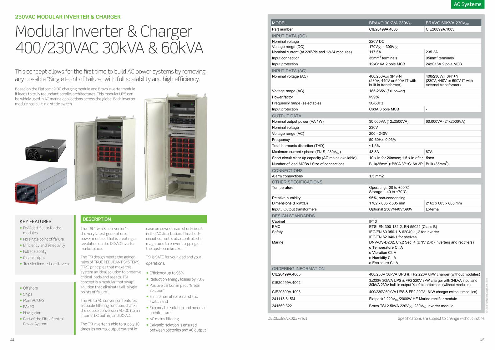
Modular Inverter & Charger 400/230VAC 30kVA & 60kVA
The TSI “Twin Sine Inverter” is the very latest generation of power modules that is creating a revolution on the DC/AC inverter marketplace.
The TSI design meets the golden rules of TRUE REDUDANT SYSTEMS (TRS) principles that make this system an ideal solution to preserve critical loads and assets. TSI concept is a modular “hot swap” solution that eliminates all “single points of failure”.
The AC to AC conversion features a double filtering function, thanks the double conversion AC-DC (to an internal DC buffer) and DC-AC.
The TSI inverter is able to supply 10 times its normal output current in
case on downstream short-circuit in the AC distribution. This short- circuit current is also controlled in magnitude to prevent tripping of the upstream breaker.
TSI is SAFE for your load and your
operations.
• Efficiency up to 96%
• Reduction energy losses by 70%
• Positive carbon impact “Green solution”
• Elimination of external static switch and
• Expandable solution and modular architecture
• AC mains filtering
• Galvanic isolation is ensured between batteries and AC output
DESCRIPTIONKEY FEATURES• DNV certificate for the
modules
• No single point of failure
• Efficiency and selectivity
• Full scalability
• Clean output
• Transfer time reduced to zero
• Offshore
• Ships
• Main AC UPS
• PA/PG
• Navigation
• Part of the Eltek Central Power System
This concept allows for the first time to build AC power systems by removing any possible “Single Point of Failure” with full scalability and high efficiency.
AC Systems Errors and O
missions Excepted
Eltek — Gråterudveien 8, PB 2340 Strømsø, 3003 Drammen, Norway Phone: +47 32 20 32 00 Eltek © 2016 – www.eltek.com
MODEL BRAVO 30KVA 230VAC BRAVO 60KVA 230VAC
Part number CIE20499A.4005 CIE20899A.1003
INPUT DATA (DC)
Nominal voltage 220V DCVoltage range (DC) 170VDC – 300VDC
Nominal current (at 220Vdc and 12/24 modules) 117.6A 235.2AInput connection 35mm2 terminals 95mm2 terminals Input protection 12xC16A 2 pole MCB 24xC16A 2 pole MCB
INPUT DATA (AC)
Nominal voltage (AC) 400/230VAC, 3Ph+N (230V, 440V or 690V IT with built in transformer)
400/230VAC, 3Ph+N (230V, 440V or 690V IT with external transformer)
Voltage range (AC) 185-265V (full power)Power factor >99%Frequency range (selectable) 50-60HzInput protection C63A 3 pole MCB -
OUTPUT DATANominal output power (VA / W) 30.000VA (12x2500VA) 60.000VA (24x2500VA)Nominal voltage 230VVoltage range (AC) 200 - 240VFrequency 50-60Hz; 0.03%Total harmonic distortion (THD) <1.5%Maximum current / phase (TN-S, 230VAC) 43.3A 87A Short circuit clear up capacity (AC mains available) 10 x In for 20msec; 1.5 x In after 15sec Number of load MCBs / Size of connections Bulk(35mm2)+B50A 3P+C16A 3P Bulk (35mm2)
CONNECTIONSAlarm connections 1.5 mm2OTHER SPECIFICATIONSTemperature Operating: -20 to +50°C
Storage: -40 to +70°CRelative humidity 95%, non-condensingDimensions (HxWxD) 1762 x 605 x 805 mm 2162 x 605 x 805 mm
Input / Output transformers Optional 230V/440V/690V External
DESIGN STANDARDS
Cabinet IP43
EMC ETSI EN 300-132-2, EN 55022 (Class B)
Safety IEC/EN 60 950-1 & 62040-1,-2 for inverterIEC/EN 62 040-1 for shelves
Marine DNV-OS-D202, Ch.2 Sec. 4 (DNV 2.4) (Inverters and rectifiers)o Temperature Cl. Ao Vibration Cl. Ao Humidity Cl. Ao Enclosure Cl. A
ORDERING INFORMATION
CIE20499A.4005 400/230V 30kVA UPS & FP2 220V 8kW charger (without modules)
CIE20499A.4002 3x230V 30kVA UPS & FP2 220V 8kW charger with 34kVA input and 30kVA 230V built in output Yan0 transformers (without modules)
CIE20899A.1003 400/230V 60kVA UPS & FP2 220V 16kW charger (without modules)
241115.815M Flatpack2 220VDC/2000W HE Marine rectifier module
241560.322 Bravo TSI 2.5kVA 220VDC, 230VAC inverter module
CIE20xx99A.x00x – rev1 Specifications are subject to change without notice
Based on the Flatpack 2 DC charging module and Bravo inverter module it leads to truly redundant parallel architectures. This modular UPS can be widely used in AC marine applications across the globe. Each inverter module has built in a static switch.
44 45

POWER SHELVES 24VDC, 48VDC, 110VDC
Flatpack2 19” 2U 8kW
The Flatpack2 has been specifically designed to meet the demand for higher density and more compact power solutions. It is suitable for applications needing an expandable, easily serviceable and reliable power supply, fitting within a small space.
The power system is monitored by Smartpack 2 controller which has all the functionality required for present and future applications.
It contains 2U of PRs (power rack) which can house 4 Flatpack2 rectifier modules.
DESCRIPTIONKEY FEATURES• Highest efficiency in
minimum space
• Scalable
• Full voltage range
• Digital controllers
• Heat management
• Unique connection
• Global approvals
APPLICATIONS• Control and Protection
• SAS System
• Communication
• Emergency lights
• Dynamic Positioning (DP)
• Thruster control
• HV switchgear control voltage
• LV switchgear control voltage
• Generator control voltage
The combination of cost-effective design, power density and reliability makes the Flatpack2 a product family that truly stands out and provides unparalleled system availability.
The versatility of the Flatpack2 rectifier means that it can be used in a wide variety of Marine & Offshore applications across the globe.
Eltek — Gråterudveien 8, PB 2340 Strømsø, 3003 Drammen, Norway Phone: +47 32 20 32 00 Eltek © 2016 – www.eltek.com
MODEL 24-60VDC 110VDC
Part number C20402.401 C20402.400
INPUT DATA
Voltage (range) 85-300VAC/DC (Nominal 185-275V)
Frequency 44 to 66Hz
Protection Varistors for transient protection, Mains fuse in both lines / Disconnect above 300V
OUTPUT DATA
Maximum voltage 36/72 VDC 122.5 VDC
Maximum current (4 modules) [email protected] 67.2A
Output protection See the rectifier’s data below
CONTROL AND MONITORING
Master controller Smartpack 2
Local Operation Display and keys or PC (PowerSuite)
Remote operation PowerSuite via modem or Monitoring via WebPower
Inputs 6xdigital (for monitoring of external equipment)
Current measurements Rectifier current and if battery shunt is used battery current and load current
Alarms Load fuse alarm, Battery fuse alarm, LVD operated, Low output voltage alarms (2 individual alarm levels), High output voltage alarms, (2 individual alarm levels), Battery capacity, Temperature alarm, Symmetry alarm
OTHER SPECIFICATIONS Isolation 3.0 kVAC – input to output, 1.5 kVAC – input and output to earth
Operating temperature -40 to 75˚C (-40 to +167˚F), Derating > 45˚C/113˚F
Storage temperature -40 to +85˚C (-40 to +185˚F), humidity 0-99% RH non-condensing
Dimensions (H x D) 482x432x89mm (2U) (WxDxH) (19x17x3.5”), recommended cabinet depth is 500mm (19.6”)
Weight Approx. 5kg (11lbs) excl. rectifier
DESIGN STANDARDS Electrical safety EN/UL 60950-1-3rd edition
EMC ETSI EN 300 386 V.1.3.2 EN 61000-6-2 / -3
Environment ETSI EN 300 019, ETS EN 300 132-2
Marine ABS (Pending)DNV-OS-D202, Ch.2 Sec. 4 (DNV 2.4) (Rectifiers)
AVAILABLE RECTIFIERS (24VDC, 48VDC, 110VDC)
Part Number Description Voltage Efficiency Maximum current OutputProtection
Range 1 Module 2 Module 3 Module 4 Module
241115.205M Flatpack 224V/1800W HE
21.7 – 28.8 V >95%(30-65% load)
75 A 150 A 225 A 300 A Fuse
241115.200M Flatpack 224V/2000W
21 – 29 V >89%(25-100% load)
84 A 168 A 252 A 336 A Blockingdiode
241115.250M Flatpack 224V/2000W WOR
21.5 – 36 V >91%(25-85% load)
70 A 140 A 210 A 280 A Fuse
241115.705M Flatpack 248-60V/2000W HE
39.9-72 V >95.5% (25-75% load)
41.6 A 83.2 A 124.8 A 166.4 A Fuse
241115.100M Flatpack 248V/2000W
43.2-57.6 V >91.5% (45-95% load)
41.6 A 83.2 A 124.8 A 166.4 A Blocking diode
241115.105M Flatpack 248V/2000W HE
43.2-57.6 V >96% (30-70% load)
41.6 A 83.2 A 124.8 A 166.4 A Fuse
241115.805M Flatpack 2110V/2000W HE
89.2-171.6 V >94%(30-70% load)
16.8 A 33.6 A 50.4 A 67.2 A Oring diode
Doc C20402.40x.DS3 - rev1 Specifications are subject to change without notice
Power Shelves Errors and O
missions Excepted
46 47

APPLICATIONS• Control and Protection
• SAS System
• Communication
• Emergency lights
• Dynamic Positioning (DP)
• Thruster control
• HV switchgear control voltage
• LV switchgear control voltage
• Generator control voltage
The combination of innovative design, efficiency and reliability makes the Flatpack S a perfect choice for Marine & Offshore and Industrial applications.
With a system depth of only 250mm, the Flatpack S system will fit in most cabinets.
With its flexible alarm and monitoring options, combined with bulk output, this 3U system is a superb building block for various marine applications.
POWER SHELVES 3X2KW 24V&48VDC, 8X1KW 24VDC
Flatpack S 19" 3U 8kW
The Flatpack S family will include models covering most applications in terms of output voltage and power, efficiency and special requirements. All rectifiers have intelligent self-protective features like reduced output power at high temperatures or low mains.
Models with increased output overvoltage protection are also available. The Flatpack S 24/1000 SIL 3 OVP, has SIL 3 on output voltage exceeding 30V. It is capable of handling double fail and has a proof test interval exceeding 15 years.
Eltek is among the market leaders in all regions in the world, and designs the core products to be compliant to all relevant standards and customer requirements.
The Flatpack S 19” 3U rack has 3 separate DC systems consisting of 2 redundant rectifiers and 1 controller or 1 common system with 8 rectifiers (8x1kW). For flexibility, two of these systems can be used in parallel to create a system with 4 rectifiers for greater power output or increased redundancy. All rectifiers have separate AC feeding (common for 8x1kW) allowing for redundant AC sources for each output.
A relay output DC okay signal is available for each pair of rectifiers. For increased monitoring and control one Smartpack S controller can be plugged in for each rectifier pair and output. In additions to more warning and alarm relay outputs, it provides setup, status and logs through the display or the Ethernet port.
FLATPACK S RECTIFIERS
GLOBAL COMPLIANCE
DC SYSTEM
KEY FEATURES• Compact and shallow
• High power density
• High efficiency
• 3 separate systems (3x2kW)
• Smartpack controllers
• SIL 3 rated output versions available
• Flexibility
Eltek — Gråterudveien 8, PB 2340 Strømsø, 3003 Drammen, Norway Phone: +47 32 20 32 00 Eltek © 2016 – www.eltek.com
MODEL FPS 3X2KW FPS 8X1KW
AC INPUT
Individual feed Single Phase for each rectifier Common Single Phase
Voltage 230 VAC/DC nominal, max 300 VAC/DC*
Current 28.2 ARMS 37.6 ARMS
Connection 2 x 2.5mm2 for each rectifier 2 x 16mm2
DC OUTPUT
Voltage 24VDC / 48VDC*
Maximum Current 3 x 83 A / system* 333.6 A
Connection 6 x 16/25mm2 (3 x VDC+ and 3 x VDC-)Can be paralleled by links
VDC+ and VDC- busbar with M6 cable lugs
OTHER SPECIFICATIONS
# rectifiers 2 position for each output (4 if paralleled) 8 positions
# controller 1 position for each output 1 position
Isolation 3.0 kVAC – input to output, 1.5 kVAC – input to earth0.5 kVDC – output to earth
Operating temp. /Storage temp. -40 to +85°C (-40 to +185°F) * / -40 to +85°C (-40 to +185°F) Mounting See the details below
MTBF > 500,000 hours Telcordia SR-332 Issue I, method III (a) (Tambient : 45°C) IEC Prot. CI. IP20 Dimensions Height: 132.5 mm (3U) / Width: 482.6 mm (to fit into 19˝mounting)
Depth: 300 mm including rear mounting brackets, 252 mm without brackets. 300 mm depth required in enclosed cabinets for air flow
CONTROL AND MONITORING Without controller
ConnectionSeries connected rectifier alarm for each rectifier pair (1)
2 x 1.5mm2; COM, NC (To be loaded with maximum 30V and 100mA)
With Smartpack SConnection
Battery current sense (2) ,Battery and load fuse sense (2), 2 LVDs (2)
10 x 1.5mm2
Temp, input and alarm output, connections on controller (2)
APPLICABLE STANDARDS Electrical safety IEC/UL 60950-1/-3rd edition EMC ETSI EN 300 386 V.1.4.1, EN 61000-6-1, -2, -3, -4, FCC Part 15 /109 Mains Harmonics EN 61000-3-2
Marine ABSDNV-OS-D202, Ch.2 Sec. 4 (DNV 2.4)Temperature Cl. B / Humidity Cl. B / Vibration Cl. AEMC Cl. B with Marine filter 241120.930
Environment ETSI EN 300 019-2-1, -2, -3, ETSI EN 300 132-2, RoHS compliant
ORDERING INFORMATION
CA0603.000 Flatpack S 24VDC 3x2kW 3U 19” with EMC filter, Rear fixing, Front conn. CA0603.001 Flatpack S 24VDC 3x2kW 3U 19”, Rear fixing, Front connection CA0603.002 Flatpack S 24VDC 3x2kW 3U 19”, Front fixing, Front connection CA0603.003 Flatpack S 24VDC 3x2kW 3U 19”, Front fixing, Rear connection CS0603.000 Flatpack S combined 24V&48VDC ,4x1kW 4x230V & 2x1kW 2x230V CS0803.001 Flatpack S 24VDC 8x1kW 3U 19”, 2x230V, Including 1 FPS 1000W HE AVAILABLE 24V RECTIFIERS
Part Number Description Voltage Efficiency Maximum current OutputProtection
Range 1Module
3Module
5Module
6Module
241122.205M Flatpack S 24V/1000W HE 21.5 – 28 V >92,5% 41.7 A 125.1 A 208.5 250.2 A Blocking diode
241122.290 Flatpack S 24V/1000W HE SILS 3
21.5 – 28 V >92,5% 41.7 A 125.1 A 208.5 250.2 A SIL 3 / diode
241122.215M Flatpack S 24V/500W HE 21.75 – 28 V >92,5% 19 A 38 A 76 A 152 A Blocking diode 241122.105M Flatpack S 48V/1000W HE 43,5 – 57,6 V >95,5% 20.9 A 62.7 A 104.5 A 125.4 A FET
Doc Cx0603.00x.DS3 - rev1 Specifications are subject to change without notice
Power ShelvesPower Shelves Errors and O
missions Excepted
48 49

POWER SHELVES 1U X 19” 48V / 24V – C+3R/C+5R/6R
Flatpack S 19” 1U
Flatpack S 24/48V combines High Efficiency and an extremely compact and short casing. With only 210 mm long modules the system fits into most applications in shallow cabinets.
Complete solutions are available in compact packages and there is flexibility to meet higher power demands in tight spaces.
The Flatpack S follows the strictest Marine & Offshore specifications, and offers 95,5% efficiency and reverse current protection.
Applications in these markets demand state of the art, reliable and safe DC power systems. The Flatpack S delivers an industry leading power density in its segment, many safety functions, wide operating temperature range and superb reliability in its small housing.
DESCRIPTION
APPLICATIONS• Control and protection
• SAS system
• Communication
• GMDSS
• Emergency lights
KEY FEATURES• Compact and shallow
• High power density
• High efficiency
• Smartpack controllers
• SIL 3 rated output versions available
• Flexibility
• Advanced control and monitoring
MODEL FLATPACK S
1U/C+3R 24VFLATPACK S 1U/C+5R 24V
FLATPACK S 1U/6R 24V
Part number CMES0301.1000 CMES0501.1001 CMES0601.1000
INPUT DATA
Voltage (nominal) 185VAC/DC - 305VAC / 300VDC
Maximum current (per feed) 12Arms 21Arms
Mains configuration 230VAC, 3 x 1 phase or 3 phase(∆) / 230/400VAC, 3 phase (Y)
Mains connection 7x4mm2 Terminal blocks, rear connection
Flying leads 2,5mm2 halogen free, 1.5 meter
Frequency 45 – 66Hz
OUTPUT DATA
Maximum voltage 28VDC
Maximum current 125.1ADC 187.5ADC 225ADC
Load connection (rear) M6 cable lug M6 cable lug M6 cable lug
Battery connection (rear) M6 cable lugShunt in positive leg - -
LVBD (LV battery disconnector) In positive leg (150A latched) - -
CONTROLLER
Smartpack S 1) External 2)
MECHANICAL DATA
Dimensions (W/H/D) 19” / 1U / 270mm (recommended minimum cabinet depth, 300mm)
Weight (without rectifiers / controller) 4.7 Kg [10.36 lbs] 2.8 Kg [6.17 lbs]
OTHER SPECIFICATIONS Operating temperature 3) -40 to +85°C (-40 to +185°F)
Coding Coding to prevent insertion of incorrect power modules Mounting Flush mount or mid mount
DESIGN STANDARDS Electrical safety UL 60950-1 2ed, EN 60950-1 2ed EMC ETSI EN 300 386 V.1.6.1 / EN 61000-6-1, -2, -3, -4 Environment ETSI EN 300 019-2-1 Class 1.2, 2.3, 3.2 Marine ABS (Rectifiers)
DNV GL-OS-D202, Ch.2 Sec. 4 (DNV 2.4) (Rectifiers)
AVAILABLE 24V RECTIFIERS
Part Number Description Voltage Efficiency Maximum current OutputProtection
Range 1 Module 3 Module 5Module
6Module
241122.205M FlatpackS 24V/1000W HE
21.5 – 28 V >92,5% 41.7 A 125.1 A 208.5 250.2 A Blocking diode
241122.290 FlatpackS 24V/1000W HE SIL
21.5 – 28 V >92,5% 41.7 A 125.1 A 208.6 250.2 A SIL 3 / diode
241122.215M FlatpackS 24V/500W HE 21.75 – 28 V >92,5% 19 A 57 A 95 A 114 A Blocking diode
241122.105M FlatpackS 48V/1000W HE
43.5 – 57.6 V >92,5% 20.9 A 62.7 A 104.5 A 125.4 A FET
OPTIONAL CONTROLLERS FPS 1U/6R
COMPACK 242100.400 SMARTPACK S PANEL MOUNT 242100.415M
SMARTPACK2 242100.500M+242100501M
Doc CMES0x01.xxxx.DS3 – rev1 Specifications are subject to change without notice
1) See applicable datasheet for Smartpack S2) Can be used with Compack, Smartpack 2 and Smartpack S controllers3) See rectifier and controller datasheet for details
Power Shelves
Flatpack S 1U Power Shelves are designed for integration into a power system. They can be used with all Flatpack S rectifiers and meet the market demand for flexible and expandable power solutions. The combination of power density, efficiency, and reliability makes the Flatpack S family a perfect choice for Marine & Offshore applications.
Errors and Om
issions Excepted
50 51

MODEL FLATPACK S
1U/C+3R 48VFLATPACK S 1U/C+5R 48V
FLATPACK S 1U/6R 48V
Part number CMES0301.1001 CMES0501.1000 CMES0601.1001
INPUT DATA
Voltage (nominal) 85 - 305VAC/DC
Maximum current (per feed) 12Arms 21Arms
Mains configuration 230VAC, 3 x 1 phase or 3 phase(∆) / 230/400VAC, 3 phase (Y)
Mains connection 7x4mm2 Terminal blocks, rear connection
Flying leads 2,5mm2 halogen free, 1.5 meter
Frequency 45 – 66Hz
OUTPUT DATA
Maximum voltage 60VDC
Maximum current 125.1ADC 187.5ADC 225ADC
Load connection (rear) M6 cable lug M6 insert nuts M6 insert nuts
Battery connection (rear) M6 cable lugShunt in negative leg - -
LVBD (LV battery disconnector) In negative leg (150A latched) - -
CONTROLLER
Smartpack S 1) External 2)
MECHANICAL DATA
Dimensions (W/H/D) 19” / 1U / 270mm (recommended minimum cabinet depth, 300mm)
Weight (without rectifiers / controller) 4.7 Kg [10.36 lbs] 2.8 Kg [6.17 lbs]
OTHER SPECIFICATIONS Operating temperature 3) -40 to +85°C (-40 to +185°F)
Coding Coding to prevent insertion of incorrect power modules Mounting Flush mount or mid mount
DESIGN STANDARDS Electrical safety UL 60950-1 2ed, EN 60950-1 2ed EMC ETSI EN 300 386 V.1.6.1 / EN 61000-6-1, -2, -3, -4 Environment ETSI EN 300 019-2-1 Class 1.2, 2.3, 3.2 Marine ABS (Rectifiers)
DNV GL-OS-D202, Ch.2 Sec. 4 (DNV 2.4) (Rectifiers)
AVAILABLE 24V RECTIFIERS
Part Number Description Voltage Efficiency Maximum current OutputProtection
Range 1 Module 3 Module 5Module
6Module
241122.205M Flatpack S 24V/1000W HE
21.5 – 28 V >92,5% 41.7 A 125.1 A 208.5 250.2 A Blocking diode
241122.290 Flatpack S 24V/1000W HE SIL
21.5 – 28 V >92,5% 41.7 A 125.1 A 208.6 250.2 A SIL 3 / diode
241122.215M Flatpack S 24V/500W HE 21.75 – 28 V >92,5% 19 A 57 A 95 A 114 A Blocking diode
241122.105M Flatpack S 48V/1000W HE
43.5 – 57.6 V >92,5% 20.9 A 62.7 A 104.5 A 125.4 A FET
OPTIONAL CONTROLLERS FPS 1U/6R
COMPACK 242100.400 SMARTPACK S PANEL MOUNT 242100.415M
SMARTPACK2 242100.500M+242100501M
Doc CMES0x01.xxxx.DS3 – rev1Specifications are subject to change without notice
Power ShelvesPower Shelves
1) See applicable datasheet for Smartpack S / 2) Can be used with Compack, Smartpack 2 and Smartpack S controllers / 3) See rectifier and controller datasheet for details
Errors and Om
issions Excepted
5352

The Flatpack S Stand-Alone Power Rack is designed to be an easy to place, high efficiency DC power solution. It can house 2 Flatpack S rectifiers, and up to 3 units can easily be stacked together. Due to its small size, flexible mounting options and reliability, this unit is a key for future needs.
COMPACT HE STAND-ALONE POWER RACK
Flatpack S Stand-Alone 24/48VDC 6kW
Flatpack S 24/48V combines High Efficiency and an extremely compact and short casing. With modules that are only 210 mm long the system fits into most shallow cabinet applications.
Complete solutions are available in compact packages and there is flexibility to meet higher power demands in tight spaces.
The Flatpack S follows the strictest Marine & Offshore specifications, and offer 95,5% efficiency and reverse current protection.
Applications in these markets demand state of the art, reliable and safe DC power systems. Flatpack S delivers an industry leading power density in its segment, with many safety functions, wide operating temperature range and superb reliability in its small housing.
The AC input filters assure compliance to DNV Rules for ships that are classified high speed & light craft and DNV offshore standards.
DESCRIPTIONKEY FEATURES• Compact and shallow
• High power density
• High efficiency
• Smartpack S controllers
• SIL 3 rated output versions available
• Flexibility
• Advanced control and monitoring
APPLICATIONS• Control and protection
• SAS system
• Communication
• GMDSS
• Emergency lights
MODEL FLATPACK S 2R
Part number 241122.902/241122.903*
INPUT DATA DIMENSIONS
Maximum voltage 305VAC / 400VDC1)
Maximum current 12Arms per feed 1)
Mains configuration 230VAC, 2 x single phase + PE
Mains connection Flying leads 1.5 mm2 / length 2 meter (* Halogen free)
Frequency 45 – 66Hz
OUTPUT DATA
Maximum voltage 60VDC
Maximum current 85A
Connections M6 cable lug
CONTROL AND MONITORING
Controller options (external) Compack, Smartpack S, Smartpack 2
Interface RJ45 for paralleling units and connect controller
Alarm connection 3-pin, galvanic isolated, max 60VDC / 100mA
MECHANICAL DATA
Dimensions See figures for details
Weight 0,910kg
MOUNTING For wall mount or mounting plate. The unit can be mounted horizontally
or vertically left or right. Additional brackets are used for 25 mm pitch and offset arrangements. Up to 3 Power Racks can be stacked.
DESIGN STANDARDS Electrical safety UL60950-1 2ed / IEC60950-1 EMC ETSI EN 300 386 V.1.6.1
EN 61000-6-1, -2, -3, -4
Environment ETSI EN 300 019-2-1, -2, -3 Marine ABS / DNV-OS-D202, Ch.2 Sec. 4
(DNV 2.4)Temperature Cl. B / Vibration Cl. A Humidity Cl. B / Enclosure Cl. A
AVAILABLE 24V RECTIFIERS
Part Number Description Voltage Efficiency Maximum current OutputProtection
Range 1Module
3Module
5Module
6Module
241122.205M Flatpack S 24V/1000W HE 21.5 – 28 V >92,5% 41.7 A 125.1 A 208.5 250.2 A Blocking diode
241122.290 Flatpack S 24V/1000W HESIL3
21.5 – 28 V >92,5% 41.7 A 125.1 A 208.6 250.2 A SIL 3 / diode
241122.215M Flatpack S 24V/500W HE 21.75 – 28 V >92,5% 19 A 57 A 95 A 114 A Blocking diode
241122.105M Flatpack S 48V/1000W HE 43.5 – 57.6 V >92,5% 20.9 A 62.7 A 104.5 A 125.4 A FET
OPTIONAL CONTROLLERS FPS 1U/6R
COMPACK 242100.400 SMARTPACK S PANEL MOUNT 242100.415M
SMARTPACK2 242100.500M+242100501M
1) See applicable datasheet for selected rectifiers
Doc 241122.903.DS3 – rev3M Specifications are subject to change without notice
Power ShelvesPower Shelves Errors and O
missions Excepted
54 55

The Portable Emergency Unit is designed to be used in situations when there is a main DC power failure, a system replacement, a battery replacement or maintenance. It's easy handling, durability and many configuration options make this unit a must to all service staff.
COMPACT, ROBUST AND EASY TO HANDLE
Portable Emergency Unit FP S 24VDC 6kW
The Portable Emergency Unit is configurable with up to four Flatpack S 24VDC, two 48VDC modules and three Smartpack S controllers. All housed in a hard case with removable lids in back and front for maximum protection during transport. By removing the lids you have easy access to connections, modules, and controllers.
The Flatpack S 19” 3U rack has 3 separate DC systems consisting of 2 redundant rectifiers and 1 controller. For flexibility two of these systems can be paralleled to create a system with 4 rectifiers for greater out power or increased redundancy. All rectifiers have separate AC feeding allowing for redundant AC sources for each output.
DESCRIPTIONKEY FEATURES• Easy to handle
• Dual voltage
• Robust
• Output power: 1kw to 4kw 24VDC + 1-3,6kw 48VDC
• Smartpack S controller
• Individual AC Input Feed
• Flexible
APPLICATIONS• Maintenance
• Replacing batteries or systems
• Failure on DC power
Power ShelvesPower Shelves
Eltek — Gråterudveien 8, PB 2340 Strømsø, 3003 Drammen, Norway Phone: +47 32 20 32 00 Eltek © 2016 – www.eltek.com
MODEL FP S 24VDC, 48VDC 6KW
Part number CIES06EP.1000
AC INPUT
Individual feed Single Phase for each rectifier
Voltage 230 VAC/DC nominal, max 300 VAC/DC1
Maximum Current 5.9 ARMS for each feed1
Connection 2 x 4mm2 for each rectifier
DC OUTPUT
Voltage 24 VDC & 48 VDC
Maximum Current See the rectifier’s data below1
Connection 24VDC+: 2x10mm2+2xC40A MCB48VDC+: 1x10mm2+1xC40A MCBDC 0V(-): 3x10mm2
OTHER SPECIFICATIONS
# rectifiers 2x2 positions for 24VDC and 2 positions for 48VDC
# controller 3x1 position
Isolation 3.0 kVAC – input to output, 1.5 kVAC – input to earth0.5 kVDC – output to earth
Operating temp. /Storage temp. -40 to +85°C (-40 to +185°F) * / -40 to +85°C (-40 to +185°F)
Dimensions Height: 210 mm Width: 570 mm Depth: 565 mm
CONTROL AND MONITORING
Rectifier alarm Series connected rectifier alarm for each rectifier pair 22 x 1.5mm2; COM, NC (To be loaded with maximum 30V and 100mA)
APPLICABLE STANDARDS Electrical safety IEC/UL 60950-1/-3rd edition
EMC ETSI EN 300 386 V.1.4.1, EN 61000-6-1, -2, -3, -4, FCC Part 15 /109
Mains Harmonics EN 61000-3-2
Environment ETSI EN 300 019-2-1, -2, -3, ETSI EN 300 132-2, RoHS compliant
Marine ABS (Rectifiers)DNV-OS-D202, Ch.2 Sec. 4 (DNV 2.4) (Rectifiers)Temperature Cl. BHumidity Cl. BVibration Cl. A
PART NUMBERS CIES03EP.1000 FPS 24+48V 3x2kW 6x230V PORTABLE EMERGENCY UNIT
AVAILABLE 24V RECTIFIERS
Part Number Description Voltage Efficiency Maximum current OutputProtection
Range 1Module
3Module
5Module
6Module
241122.205M Flatpack S 24V/1000W HE 21.5 –28 V
>92,5% 41,7 A 125,1 A 208,5 250,2 A Blocking diode
241122.290M Flatpack S 24V/1000W HE SIL 21.5 –28 V
>92,5% 41,7 A 125,1 A 208,5 250,2 A SIL 3 / diode
241122.215M Flatpack S 24V/500W HE 21.75 –28 V
>92,5% 19 A 57 A 95 A 114 A Blocking diode
241122.105M Flatpack S 48V/1000W HE 43,5 –57,6 V
>92,5% 20,9 A 62,7 A 104,5 A 125,4 A FET
241122.125M Flatpack S 48V/1800W HE 43,5 –57,6 V
>95,8% 37,5 A 112,5 A 187,5 A 225 A FET
(1) see rectifier datasheet for details, (2) see Smartpack S datasheet for details
Doc CIES03EP.1000.DS3 – rev1 Specifications are subject to change without notice
570X210X565mm (W/H/D)
Errors and Om
issions Excepted
56 57

The combination of cost-effective design, power density and reliability makes the Flatpack2 a product family that truly stands outs and provides unparalleled network availability.
The Flatpack2 HE stands out. With efficiency up to 96.5%, power losses have been reduced by 50% compared to the current industry standard. WOR (wide output range) rectifiers have optimized output voltage windows for use with any type of batteries.
The versatility of the Flatpack2 rectifier means that it can be used in a wide variety of Marine & Offshore applications across the globe.
HIGH EFFICIENCY AND RELIABLE RECTIFIERS
Flatpack2 Rectifiers
Since setting the new standard for rectifier efficiency, the Flatpack2 HE family is now available in a variety of voltages and power ratings, all with superior efficiency up to 96.5%.
With more than 4 billion in-field operating hours and a proven cumulative field MTBF of more than 1,9 million hours, Flatpack2 HE is the only HE (High Efficiency) rectifier with a proven track record.
DESCRIPTION
KEY FEATURES• Highest efficiency in minimum space
• Resonant topology makes the module efficiency industry leading and contributes to the rectifier’s ultra compact dimensions.
• Digital controllers
• The number of components have been reduced by 40% - for highly reliable, long life, trouble free DC power systems.
• Heat management
• Front-to-back airflow with chassis-integrated heat sinks and no limitations in the scalability of the desired system solution.
• Unique connection
• Time - to- install and cost-reducing solution.
• Global approvals
• Flatpack2 WOR is CE and UL certified
• DNV and ABS(pending) certification
APPLICATIONS• Control and protection
• SAS systems
• PA Systems
• Communication
• Emergency lights
MODEL 24/2000 24/1800 HE 24/2000 WOR
Part number 241115.200M 241115.205M 241115.250M
INPUT DATA
Voltage (nominal range) 175 VAC - 275 VAC 185 VAC/DC - 275 VAC/DC 185 VAC - 275 VAC
Voltage (operating range) 85 VAC - 290 VAC 85 VAC/DC - 300 VAC/DC 85 VAC - 300 VAC
Frequency (nominal / range) 44 to 66Hz 0 to 66Hz 44 to 66Hz
Maximum current 13 ARMS 11.25 ARMS 12,5 ARMS
Power Factor > 0.99 at 50% load or more
Protection
Varistors for transient protection,Mains fuse in both lines,Disconnect above 290 VAC
Varistors for transient protection,Mains fuse in both linesDisconnect above 300 VAC
OUTPUT DATA
Voltage (default) 26.7 VDC
Voltage (adjustable range) 21 - 29 VDC 21.7 - 28.8 VDC 21.5 - 36 VDC
Max power, nominal input 2000 W 1800 W 2000 W
Max current 84 A (@VOUT < 24 VDC) 75 A (@VOUT = 24 VDC) 70 A (@VOUT = 29 VDC)
Current sharing ±5% of maximum current from 10 to 100% load Static voltage regulation
(10-100% load) ±0.5%
Dynamic voltage regulation ±5.0% for 10-90% or 90-10% load variation, regulation time < 50ms Hold up time >20ms; output voltage > 21.5 VDC >20ms; output voltage > 21 VDC >20ms; output voltage > 21.5 VDC
Ripple < 100 mVPP , 30 MHz bandwidth < 250 mVPP , 30 MHz bandwidth < 100 mVPP , 30 MHz bandwidth
Protection
Overvoltage shutdown,Blocking diode,Short circuit proof, High temperature protection
Overvoltage shutdown,Fuse on output,Short circuit proof,High temperature protection
OTHER SPECIFICATIONS Peak Efficiency 91.0% 95.0% 91.0% Isolation 3.0 kVAC – input and output, 1.5 kVAC – input earth, 0.5 kVDC – output earth
Alarms (Red LED) Low mains shutdown, High and low temperature shutdown, Rectifier Failure, Overvoltage shutdown on output, Fan failure, Low voltage alarm, CAN bus failure
Warnings (Yellow LED)
Low temperature shutdown, Rectifier (Converter) in power derate mode, Remote battery current limit activated, Input voltage out of range, flashing at overvoltage, Loss of CAN communicationwith control unit, Stand alone mode
Normal (Green LED) Input and output ok
Cooling 2 fans (front to back airflow) Single fan (front to back airflow) 2 fans (front to back airflow)
Fan Speed Temperature and load regulated
Acoustic Noise < 65dBA at nominal input and 70%
load (Tambient < 30°C)
at nominal input and full load< 40dBA (Tambient <= 25°C)< 58dBA (Tambient > 40°C)
< 65dBA at nominal input and 70% load (Tambient < 30°C)
MTBF (Telcordia SR-332Iss.I method III (a)) > 200 000 (@ Tambient : 25 °C) > 300 000 (@ Tambient : 25 °C) > 200 000 (@ Tambient : 25 °C)
Operating temperature (5 -95% RH non-cond.) - 40 – 75°C (-40 – 167°F)
Max output power de-rates above temp / to 45°C [+113°F] / 1400 W 45°C [+113°F] / 1200 W 45°C [+113°F] / 1400 W
Storage temperature -40 to +85°C (-40 to +185°F), humidity 0 - 99% RH non-condensing
Dimensions [WxHxD] / Weight
109 x 41.5 x 327mm (4.25 x 1.69 x 13”) / < 1.9 kg (3.97 lbs)
DESIGN STANDARDS Electrical safety IEC 60950-1, UL 60950-1, CSA 22.2 EMC ETSI EN 300 386 V.1.3.2,
EN 61000-6-1 / -2 / -3 / -4ETSI EN 300 386 V.1.4.1, EN 61000-6-1 / -2 / -3 / -4
ETSI EN 300 386 V.1.3.2 , EN 61000-6-1 / -2 / -3 / -4
Mains Harmonics EN 61000-3-2
Environment
ETSI EN 300 019-2ETSI EN 300 132-2Telcordia NEBS GR63 CORE Zone 4RoHS compliant
ETSI EN 300 019-2-1 Class 1.2, 2.3, 3.2ETSI EN 300 132-2RoHS compliant
ETSI EN 300 019-2ETSI EN 300 132-2Telcordia NEBS GR63 CORE Zone 4RoHS compliant
Marine
ABS (Pending),DNV-OS-D202, Ch.2 Sec. 4 (DNV 2.4),Temperature Cl. A,Vibration Cl. A,Humidity Cl. A
Doc 241115.xxx.DS3 – rev1 Specifications are subject to change without notice
Rectifiers Errors and O
missions Excepted
58 59

MODEL 48/2000 HE 48/2000 HE WOR 110/2000 HE WOR 220/2000 HE WOR Part number 241115.105M 241115.705M 241115.805M 241115.815M
INPUT DATA
Voltage (nominal range) 185 VAC/DC - 275 VAC/DC 185 VAC - 275 VAC 185 VAC/DC - 275 VAC/DC 185 VAC - 275 VAC
Voltage (operating range) 85-300 VAC / 140-275 VDC 85 VAC - 300 VAC 85 VAC/DC - 300 VAC/DC 85 VAC - 300 VAC
Frequency (nominal / range) 45 to 66Hz / 0Hz 0 to 66Hz 0 to 66Hz Maximum current 11.6 ARMS 11.9 ARMS 11.9 ARMS
Power Factor > 0.99 at 50% load or more
ProtectionFuse in both linesVaristor for transient protection, Disconnect above 300 VAC/DC
Fuse in both linesVaristor for transient protection, Disconnect above 300 VAC
Fuse in both lines,Varistor for transient protectionDisconnect above 300 V
OUTPUT DATA
Voltage (default) 53.5 VDC53.5 VDC (48V) 67 VDC (60V) 122.5 VDC 245.3 VDC
Voltage (adjustable range) 43.5 - 57.6 VDC 39.9 - 72 VDC 89.2 - 171.6 VDC 178.5 - 297 VDC
Max power, nominal input 2000 W
Max current 41.7 A 41.6 A 16.7 A 9.16 A Current sharing ±5% of maximum current from 10 to 100% load Static voltage regulation (10-100% load) ±0.5% Dynamic voltage regulation ±5.0% for 10-90% or 90-10% load variation, regulation time < 50ms Hold up time - >20ms; output voltage >
53.5 VDC- -
Ripple < 100 mVPP , 30 MHz bandwidth
< 150 mVPP , 30 MHz bandwidth < 200 mVPP , 20 MHz bandwidth
Protection Fuse, Short circuit proof, High temperature protection,
Hot plug-in inrush current limiting
Short circuit proof, OR-ing diode, High temperature protection, Hot plug-in inrush current limiting, Over voltage Shutdown
OTHER SPECIFICATIONS Peak Efficiency 96.5% 96.0% 91,7 % 93,8 %
Isolation3.0 kVAC – input and output, 1.5 kVAC – input earth, 0.5 kVDC – output earth
1.2 kVDC - input to chassis 1.9 kVDC - CAN tochassis1.9 kVDC - input to output 1.9 kVDC - CAN to input1.0 kVDC - output to chassis 1.9 kVDC - CAN to output
Alarms (Red LED) Low mains shutdown, High and low temperature shutdown, Rectifier Failure, Overvoltage shutdown on output, Fan failure, Low voltage alarm, CAN bus failure
Warnings (Yellow LED) Low temperature shutdown, Rectifier (Converter) in power derate mode, Remote battery current limit activated, Input voltage out of range,flashing at overvoltage, Loss of CAN communicationwith control unit, Stand alone mode
Normal (Green LED) Input and output ok
Cooling Fan (front to back airflow) Fan (front to back airflow)
Fan Speed Temperature and load regulated
Acoustic Noiseat nominal input and full load< 20dBA Tambient <= 25°C)< 56dBA (Tambient > 40°C)
< 52dBA at nominal input and full load (Tambient < 30°C)
at nominal input and full load< 40dBA (Tambient <= 25°C)< 58dBA (Tambient > 40°C)
MTBF (Telcordia SR-332 Iss.I method III (a)) > 391 000 (@ Tambient : 25 °C) >391 000 (@ Tambient : 25 °C)
Operating temperature - 40 – 75°C (-40 – 167°F) (5 - 95% RH non-cond.) Max output power de-rates
above temp/to 45°C [+113°F] / 1200 W 55°C [131°F] / 1350W
Storage temperature -40 to +85°C (-40 to +185°F), humidity 0 - 99% RH non-condensing Dimensions [WxHxD] / Weight 109 x 41.5 x 327mm (4.25 x 1.69 x 13”) / < 1.95 kg (3.97 lbs)
DESIGN STANDARDS Electrical safety IEC 60950-1, UL 60950-1, CSA 22.2 IEC 60950-1, UL 60950-1, CSA 22.2
EMCETSI EN 300 386 V.1.4.1 , EN 61000-6-1 / -2 / -3 / -4, Telcordia NEBS GR1089 CORE
ETSI EN 300 386 V.1.3.2 , EN 61000-6-1 / -2 / -3 / -4, Telcordia NEBS GR1089 CORE
ETSI EN 300 386 V.1.4.1 (1.3.2) , EN 61000-6-1 / -2/ -3 / -4 / -5
Mains Harmonics EN 61000-3-2 - EN 61000-3-2
EnvironmentETSI EN 300 019: 2-1 (Class 1.2), 2-2 (Class 2.3) & 2-3 (Class 3.2), ETSI EN 300 132-2 / Telcordia NEBS GR63 CORE Zone 4, OHS compliant
ETSI EN 300 019: 2-1(Class 1.2), 2-2(Class 2.3) &2-3(Class 3.2), RoHS (2011/65/EU) and WEEE (2002/96/EC) compliant
Marine
ABS (Pending), DNV-OS-D202, Ch.2 Sec. 4 (DNV 2.4),Temperature Cl. A, Vibration Cl. A, Humidity Cl. A
MODEL 24/1350 HE DC/DC 48/1350 HE DC/DC 48/2000 Part number 241115.600 241115.602 241115.100
INPUT DATA
Voltage (nominal range) 20 - 75 VDC (shutdown < 16.5VDC) 185 VAC - 275 VAC
Voltage (operating range) - 85 VAC - 300 VAC
Frequency (nominal / range) - 44 to 66Hz Maximum current 70 ADC (85 ADC during boost) 12.5 ARMS
Power Factor - > 0.99 at 50% load or more Protection Fuse and reversed polarity protection Varistors for transient protection, Mains fuse
in both lines, Disconnect above 290 VAC
OUTPUT DATA
Voltage (default) 26 VDC 53 VDC 53.5 VDC Voltage (adjustable range) 24 - 28 VDC 48 - 58.5 VDC 43.5 - 57.6 VDC Max power, nominal input 1350 W 1350 W 2000 W Max current 56 A 28 A 41.7 A Current sharing - ±5% of maximum current from 10to100%load Static voltage regulation
(10-100% load) ±1% (0-100% load) ±0.5% (0-100% load) ±0.5%
Dynamic voltage regulation±5.0% for 10-90% or 90-10% load variation, regulation time < 30ms
±5.0% for 10-90% or 90-10% load variation, regulation time < 50ms
Hold up time - >20ms; output voltage > 43.5 VDC Ripple < 200 mVPP , 20 MHz bandwidth < 100 mVPP , 30 MHz bandwidth
ProtectionShort circuit proof, OR-ing diode, High temperature protection, Hot plug-in inrush current limiting,Over voltage Shutdown
ORing diode, Short circuit proofHigh temperature protection,Overvoltage shutdown
OTHER SPECIFICATIONS Peak Efficiency 91,7 % 93,8 % 92.5%
Isolation1.2 kVDC - input to chassis 1.9 kVDC - CAN to chassis1.9 kVDC - input to output 1.9 kVDC - CAN to input1.0 kVDC - output to chassis 1.9 kVDC - CAN to output
3.0 kVAC – input and output, 1.5 kVAC – input earth, 0.5 kVDC – output earth
Alarms (Red LED)Low mains shutdown, High and low temperature shutdown, Rectifier Failure, Overvoltage shutdown on output, Fan failure, Low voltage alarm, CAN bus failure
Low mains shutdown, High and low temperature shutdown, Rectifier Failure, Overvoltage shutdown on output, Fan failure, Low voltage alarm, CAN bus failure
Warnings (Yellow LED)
Low temperature shutdown, Rectifier (Converter) in power derate mode, Remote battery current limit activated, Input voltage out of range,flashing at overvoltage, Loss of CAN communicationwith control unit, Stand alone mode
Low temperature shutdown, Rectifier (Converter) in power derate mode, Remote battery current limit activated, Input voltage out of range,flashing at overvoltage, Loss of CAN, communicationwith control unit, Stand alone mode
Normal (Green LED) Input and output ok
Cooling Fan (front to back airflow) 2 fans (front to back airflow) Fan (front to back airflow) Fan Speed Temperature and load regulated Acoustic Noise < 65dBA < 55dBA at nominal input and full load
(Tambient < 30°C) MTBF (Telcordia SR-332
Iss.I method III (a)) >315 000 (@ Tambient : 25 °C) > 391 000 (@ Tambient : 25 °C)
Operating temp.(5 - 95% RH non-cond.) - 40 – 75°C (-40 – 167°F) Max output power de-rates above
temp/to 55°C [131°F] / 800W 45°C [+113°F] / 1350 W
Storage temperature -40 to +85°C (-40 to +185°F), humidity 0 - 99% RH non-condensing Dimensions [WxHxD] / Weight 109 x 41.5 x 327mm (4.25 x 1.69 x 13”) / < 1.9 kg (3.97 lbs) 109 x 41.5 x 327mm (4.25 x 1.69 x 13”) /
< 1.9 kg (3.97 lbs)DESIGN STANDARDS
Electrical safety UL 60950-1, EN 60950-1
UL 60950-1:2007, IEC 60950-1:2005 + A1:2009 / EN 60950-1: 2006 + A11:2009 + A1:2010 + A12:2011
EMC ETSI EN 300 386 V.1.4.1 , EN 61000-6-1 / -2 / -3 / -4 ETSI EN 300 386 V.1.6.1 , EN 61000-6-1 / -2 / -3 / -4, Telcordia NEBS GR1089 CORE
Mains Harmonics - -
EnvironmentETSI EN 300 019: 2-1(Class 1.2), 2-2(Class 2.3) & 2-3(Class 3.2) / RoHS (2011/65/EU) and WEEE (2002/96/EC) compliant
ETSI EN 300 019: 2-1 (Class 1.2), 2-2(Class 2.3) & 2-3 (Class 3.2), ETSI EN 300 132-2 / Telcordia NEBS GR63 COREZone 4, OHScompliant
Marine
ABS (Pending)DNV-OS-D202, Ch.2 Sec. 4 (DNV 2.4) (Pending)Temperature Cl. A, Vibration Cl. A, Humidity Cl. A
ABS (Pending), DNV-OS-D202, Ch.2 Sec. 4 (DNV 2.4), Temperature Cl. A,Vibration Cl. A, Humidity Cl. A
Doc 241115.xxx.DS3 – rev1Doc 241115.xxx.DS3 – rev1 Specifications are subject to change without noticeSpecifications are subject to change without notice
Rectifiers Errors and O
missions Excepted
60 61

Eltek — Gråterudveien 8, PB 2340 Strømsø, 3003 Drammen, Norway Phone: +47 32 20 32 00 Eltek © 2016 – www.eltek.com
MODEL 24/500 HE 24/1000 HE 24/1000 HE SIL 3 48/1000 HE
Part number 241122.215M 241122.205M 241122.290 241122.105M
INPUT DATA
Voltage (nominal range) 185 VAC/DC - 305 VAC / 300VDC 185 - 270 VAC / 185 - 250 VDC1)
Voltage (operating range) 85 VAC/DC - 305 VAC / 300VDC 85 - 300 VAC / 85 - 250 VDC1)
Frequency (nominal / range) DC, 45 - 66 Hz / 0-66Hz 45 - 66 Hz / 0 Hz1)
Maximum current 3.2 ARMS1) 5.9 ARMS
Power Factor > 0.975 at 75% load or more
> 0.99 at 50% load or more
Protection Fuse / Shutdown above 305 VAC / VDC Fuse in L & N, Varistor /Shutdown when input voltage is out of operating range
OUTPUT DATA
Voltage (default) 26.7 VDC 53.5 VDC
Voltage (adjustable range) 21.75 - 28 VDC 21.5 - 28 VDC 43.5 - 57.6 VDC
Max power, nominal input 500 W 1000 W
Max power, @ 85 VAC/DC 200 W 440 W 420 W
Max current 19 A (@VOUT<24 VDC) 41.7 A (@VOUT < 24 VDC) 20.9 A (@VOUT <48VDC)
Current sharing ±5% of maximum current from 10 to 100% load
Static voltage regulation (10-100%load) ±0.5%
Dynamic voltage regulation ±5.0% for 10-90% or 90-10% load variation, regulation time < 50ms
Hold up time >20ms; output voltage > 21 VDC >20ms;output voltage >41VDC
Ripple< 160 mVPP , 30 MHz bandwidth
< 150 mVPP , 30 MHz bandwidth
< 200 mVPP , 30 MHz bandwidth
< 150 mVPP , 30 MHz bandwidth
Protection Blocking OR-ing Diode, Short circuit proof, Over voltage protection and
High temperature protection
ORing FET, Short circuit proof, High temperature protection, Over voltage Shutdown
Overvoltage protection, SIL3 parameters
-Protection level: 30V Proof test interval: 15 years. Handles dual component failure
-
OTHER SPECIFICATIONS Peak Efficiency 92,5 % 95,5 % Isolation 3.0 kVAC – input and output, 1.5 kVAC –
input earth, 0.5 kVDC – output earth3.0 kVAC – input and output, 1.5 kVAC– input earth, 710 VDC – output earth
Alarms (Red LED) Low mains shutdown, High and low temperature shutdown, Rectifier Failure, Overvoltage shutdown on output, Fan failure, Low voltage alarm, CAN bus failure
Warnings (Yellow LED) Rectifier in power de-rate mode, Remote battery current limit activated, Input voltage out of range, flashing at overvoltage
Normal (Green LED) Input and output ok
Potential alarm relay Opens on alarms and mains outage (normally closed) MTBF (Telcordia SR-332 Iss.I
method III (a))> 300 000 (@ Tambient : 25 °C) > 315 000 (@ Tambient : 25 °C)
Operating temperature (5 - 95% RH non-cond.) - 40 – 85°C [-40 – 185°F ] Max output power de-rates
above temp / to45°C [+113°F] / 260W 45°C [+113°F] / 400 W 45°C [113°F] / 600W
Storage temperature -40 to +85°C (-40 to +185°F), humidity 0 - 99% RH non-condensing Dimensions
[WxHxD] / Weight72 x 41.5 x 217mm (2.83 x 1.63 x 8.54”) / < 850 g (1.9 lbs)
72 x 41.5 x 217mm (2.83 x 1.63 x 8.54”) / < 1 kg (2 lbs)
72 x 41.5 x 217mm (2.83 x 1.63 x 8.54”) / < 850 g (1.9 lbs)
DESIGN STANDARDS Electrical safety EN 60950- 1:2006+A11:2009
+A1:2010+A12:2011,UL 60950-1:2011UL 60950-1, EN 60950-1, IEC 61508
UL 60950-1, EN 60950-1
EMC EN 61000-6-1:2007, -6-2:2005, -6-3:2007 + A1:2011, -6-4: 2007 + A1:2011, TS 61000-6-5, EN 300 386:v1.6.1, FCC CFR 47 Part15:2013
ETSI EN 300 386 V.1.4.1 , EN 61000-6-1 / -2 / -3 / -4 / -5 ,FCC Part 15 Subpart 109
ETSI EN 300 386, EN 61000-6-1 / -2 / -3 / -4 TS 61000-6-5, FCC CFR 47 Part 15
Environment ETSI EN300 019: 2-1(Class 1.2), 2-2 (Class 2.3) & 2-3 (Class 3.2) 2011/ 65/EU(RoHS)&2008/98/EC(WEEE)
ETSI EN 300 019: 2-1 (Class 1.2), 2-2(Class 2.3) & 2-3(Class 3.2) / RoHS (2011/65/EU)
ETSI EN 300 019: 2-1 (Class 1.2), 2-2 (Class 2.3) & 2-3(Class 3.2) / RoHS (2011/65/EU) and WEEE (2002/96/EC) compliant
ETSI EN 300 019: 2-1 (Class 1.2), 2-2(Class 2.3) & 2-3 (Class 3.2)RoHS (2011/65/EU) and WEEE (2002/96/EC) compliant
Marine ABS, DNV-OS-D202, Ch.2 Sec. 4 (DNV 2.4), Temperature Cl. B / Vibration Cl. A / Humidity Cl. B
The Flatpack S rectifiers incorporate Marine specifications, high efficiency, ORing protection on output and high power in a small, 217 mm deep box.
Applications in these markets demand state of the art, reliable and safe DC power systems. The Flatpack S delivers an industry leading power density in its segment, many safety functions, wide operating temperature range and superb reliability with low heat dissipation.
The Flatpack S 24/1000 SIL 3 OVP targets Safety and Automation Systems (SAS) in offshore and process industries requiring SIL 3 rated overvoltage protection on DC output.
500W & 1000W HE 24/48V
Flatpack S Rectifiers
DESCRIPTION
APPLICATIONS• Control and protection
• SAS systems
• PA Systems
• Communication
• GMDSS (24V modules are acc. to IEC 60945)
• Emergency lights
DESCRIPTIONKEY FEATURES• Small
• Short
• Power density - 47W/Inch 3
• High efficiency
• Oring protection on output
• Hot pluggable
• Voltage and power keying
• Accepts DC input (DC/DC converter)
• Alarm relay output - basic monitoring without controller
• SIL 3 rated output
• Overvoltage protection
• Meets DNV class B and IEC 60945
Doc 241122.xxx.DS3 – rev1 Specifications are subject to change without notice
1) DC input only allowed when up-stream breaker is rated for the applicable DC input voltage and has a maximum current rating of 32A / 2) For HW revisions 1 - 1.31, nominal range is 207 - 277 VAC / 207 - 250 VDC, maximum output power at 176 VAC/DC is 1180 W with further linear de-rating to 90W at 122 VAC/DC. Not to be used in applications with 110/120 VAC mains.
Rectifiers
Flatpack S 24/48V combines High Efficiency and an extremely compact and short casing. With only 217 mm long modules it fits into most applications in the shallow cabinets.
Complete solutions are available in compact packages and there is flexibility to meet higher power demands in tight spaces.
Complete solutions are available in compact packages and there is flexibility to meet higher power demands in tight spaces.
The Flatpack S follows the strictest Marine & Offshore specifications, 95,5% efficiency and reverse current protection.
Errors and Om
issions Excepted
62 63

MODEL 12V / 120W 24V / 240W 48V / 250W
Part number 241120.300 241120.200 241120.100
INPUT DATA
Voltage range 85 - 300 VAC/DC1)
Voltage range (nominal) 130 - 275 VAC/DC 185 - 275 VAC/DC1)
Frequency 0 - 66 Hz 1)
Maximum current, 230V input / overall (boost) 0.6 A / 2.0 A 1.2 A / 2.0 A 1.2 A / 1.9 A
Maximum earth leakage current 2.0 mA (@ 250VAC/50Hz)
Power Factor 0.97 (@ 70 - 100 % load) 0.98 (@ 55 - 100 % load) 0.98 (@ 50 - 100 % load)
THD (@ 230 VAC) < 5 % (@ 80 - 100 % load) < 5 % (@ 50 - 100 % load) < 5 % (@ 50 - 100 % load)
Protection Varistor for transient protection, fuse in both lines (2x 2.0 A), shutdown above 300 VAC/DC
OUTPUT DATA
Default voltage 13.6 VDC 27.2 VDC 53.5 VDC
Voltage range 10.7 - 18.0 VDC 21.5 - 36 VDC 43.5 - 57.6 VDC
Voltage range without controller 10.7 - 15.0 VDC 21.5 - 30 VDC 43.5 - 57.6 VDC
# Pb cell supported (1.8 - 2.4 VDC/cell) 6 - 7 12 - 15 24
# NiCad cell supported (1.05 - 1.65 VDC/cell) 10 - 112) 20 - 222) -
Max power, nominal / 60s boost 120 W / 160 W 240 W / 315 W 250 W / -
Max current, @12/24/48VDC / boost / QT3) 10 A / 15 A / 55 A 10 A / 15 A / 55 A 5 A / - / -
Current sharing ±5% of maximum current from 10 to 100% load
Static voltage regulation ±0.5% from 10% to 100% load and nominal input
Dynamic voltage regulation ± 5 % < 10ms, load step 10% to 90% or opposite at nominal output voltage
Hold-up time, default voltage and full power 20 ms, VOUT > 10.7 VDC 20 ms, VOUT > 21.5 VDC 20 ms, VOUT > 43 VDC
Rippel and noise, 30 MHz b.w. / psophometric < 200 mVPP / 5 mVRMS < 200 mVPP / 5 mVRMS < 150 mVPP / 2 mVRMS
Protection Overvoltage shutdown, short circuit proof, high temperature, hot plug-in inrush current limiting, fuse
OTHER SPECIFICATIONS
Efficiency @ nominal input/output, peak/range 89.5% / >88%, 50-100% load 93.0% / >92%, 50-100% load 93.6% / >93%, 50-100% load
Isolation 3.0 kVAC – input and output, 1.5 kVAC – input earth, 0.5 kVDC – output earth
Alarms: Red LED 'on' Low mains shutdown, High and low temperature shutdown, Rectifier Failure, Overvoltage shutdown on output, Fan failure, Low voltage alarm, CAN bus failure
Warnings: Yellow LED 'on' Rectifier in power derate mode, Remote battery current limit activated, Input voltage out of range, flashing at overvoltage
Normal (module running): Green LED 'on'
Alarm output (isolated) NO (+positive terminal), COM (-negative terminal). 60 V / 100 mA max
MTBF (Telcordia SR-332 Issue I method III (a))
>480 000h (@TAMBIENT= 25°C)
>480 000h (@TAMBIENT= 25°C)
>500 000h (@TAMBIENT= 25°C)
Operating temperature (5 - 95% RH non-cond.)Output power de-rates above temp / to
-40 to +70°C [-40 — +158°F]+55°C / 50W @ +70°C
-40 to +60°C [-40 to +142°F]+45°C / 80W @ +60°C
-40 to +75°C [-40 to +167°F]+55°C / 140W @ +75°C
Storage temperature -40 to +85°C (-40 to +185°F), humidity 0 - 99% RH non-condensing
Dimensions[WxHxD] / Weight 39.0 x 88.5 x 149mm [1.54 x 3.48 x 5.87"] / 0.5 kg [1.1 lbs]
DESIGN STANDARDS
Electrical safety UL 60950-1, EN 60950-1, CSA 22.2
EMC ETSI EN 300 386 V.1.3.2 EN 61000-6-1 / -2 / -3 / -4 / -54)
Mains Harmonics EN 61000-3-2Environment ETSI EN 300 019: 2-1 (Class 1.2), 2-2 (Class 2.3) & 2-3 (Class 3.2)
ETSI EN 300 132-22002/95/EC (RoHS) & 2002/96/EC (WEEE)
Marine compliance (EMC class B with AC filter)
DnV Rules for Classification of Ships, High Speed & Light Craft and DnV Offshore Standards
COMPACT, FULL-FEATURED DIN-RAIL POWER SYSTEM
Micropack Rectifiers 12VDC/120W, 24-30VDC/240W & 48VDC/250W
APPLICATIONS• Telecom
» LTE/femto cells
» Small base stations / repeaters
» Fixed & mobile broadband
» FTTx
• Power utilities
» Control & protection
» Scada
» Communication
• Railway infrastructure
» Control & protection
» Signaling
• Various other applications in demanding industries like Marine, Oil & Gas, process etc.
KEY FEATURES• Convection cooled – inaudible
• Accepts 85 – 300 VAC/DC input
• 12, 24-30, 48 VDC output versions
• NiCad support for 12 and 24VDC
• Quick-trip pulse to help open load MCB
• Pot-meter voltage adjustment for standalone
• Module alarm relay contact for basic monitoring without controller
• Active current sharing
• Comprehensive monitoring and control when used with controller:
» Remote/local connection through Ethernet
» Webpages and SNMP support
» Monitoring of rectifier temperature, input
voltage and output current
• Modular approach in DIN-rail mountable back planes
• Off-the-shelf delivery
Micropack Rectifiers Compack Controller
Rectifiers
Doc 241120.123xx.DS3 – v2
Errors and Om
issions Excepted
1) DC support for 241120.200 with primary FW 404088.009 (from HW revision 1.2) and 241120.100 from HW revision 2 2) 11/22 cells with max boost voltage 1.636 VDC/cell 3) Quick-Trip function, if VOUT = 5 VDC a 35 ms current pulse is generated to help trip fuse/MCB on short circuited branch 4) Only 12V and 24V
The Micropack System is convection cooled, designed for less power hungry applications, but still with system functionality options to match any requirements. Use as stand alone or in a flexible off the shelf configurable system.
The Micropack Power System extends your network one step further. With load ranges typically between 120W and 1000W, and in 12, 24 and 48V options, the system is perfect for a great variety of applications.
Specifications are subject to change without notice64 65

MODEL FLATPACK S MARINE SYSTEM 8KW, 24VDC
Part number CS0816.000
MARINE FILTER MICROPACK SYSTEM BUILDING BLOCKS - COMPABILITY MATRIX
DIN Rail Marine filter (241120/930)
Output Voltage Output grounding Supports
Part number Description 12V 24V 48V DC+ DC- FLOAT Rectifier DC/DC
241120.900 Powercore -1
241120.901 Powercore -2
241120.902 Powercore -4
241120.905 Powercore -1
241120.907 Powercore -4
241120.910 Batt dist. 1) 3)
241120.911 Bulk feed 4)
241120.912
Bulk feed LVD 12
241120.914
Bulk feed LVD 24/48
241120.915
Batt dist. 24/48 1)
241120.920 Load dist. 1)
251875
Dummy Module
241120.930 Marine filter2)
RECTIFIER POWER CORES
A few quick steps……
o Start with a DIN railo Clip on and lock the desired power core; 2 or 4 rectifier
positions or stand aloneo Clip on and fasten either the bulk feed unit or battery
distribution (for 2 or 4 pos power cores)o Clip on and fasten the load distribution (if applicable)o Do the wiring
o In marine applications, clip on the Marine Filter Unit and connect the AC feed through it.
o Plug in the battery and load breakerso Plug in the rectifier modules and controllero Install covers for the distributions, bulk feed and
blind panel for any unused rectifier positions if applicableS
…and you’ll have a complete DC system.
MODEL BATTERY DIST. BULK FEED BULK FEED LVD LOAD DIST.
Part number 241120.910 / .915 241120.911 241120.912 /.914 241120.920
OUTPUT DATA System voltage support -48 / -24 – -48 VDC ±12 – ±48 VDC +12 / +24 – +48 VDC -12 – -48 VDC
Unprotected bulk output connections - 1 (Max 10 mm2) 1 (Max 10 mm2) -
Protected load output connections(plug-able single pole MCB in negative) - - - 4 x 2 - 15 A
(Max 4 mm2)
Connection to Load dist (241120.920) • • • •
Unprotected battery output connections(shunt and LVBD in positive) - - 1
(Max 10 mm2) -
Protected battery output connections(single pole MCB, shunt and LVBD in negative)
2 x max 30 A(Max 10 mm2) - - -
Output Protection in rectifiers/converters Blocking OR-ing FET or fuse, Short circuit proof and High temperature protection
OTHER SPECIFICATIONS Control system connection terminals CAN (1 x RJ45) CAN (1 x RJ45)
2 x LVD2 x fuse fail1 x current shunt
CAN (1 x RJ45)1 x LVD2x fuse fail1 x earth fault
-
Extending width 66 mm [2.6”] 26 mm [1.0”] 66 mm [2.6”] 73 mm [2.9”]
Weight 270 g [0.6 lbs] 110g [0.24 lbs] 250 g [0.6 lbs] 165 g [0.3 lbs]
Doc 241120.90x.DS3 – rev7Doc 241120.90x.DS3 – rev7Specifications are subject to change without notice
Rectifiers Errors and O
missions Excepted
2-positions (241120.901)
MODEL FLATPACK S MARINE SYSTEM 8KW, 24VDC
RECTIFIER POWER CORES RECTIFIER POWER CORES
RECTIFIER POWER CORES RECTIFIER POWER CORES
Standalone (241120.905)
4-positions (241120.907)
Battery distribution with shunt, LVBD and sockets for 2 breakers
(241120.910 for 48 VDC only) (241120.915 for 24 - 48 VDC)
Load distribution with sockets for 4 breakers
(241120/920)
Bulk feed output (241120.911)
Standalone (241120.900)
2-POS (241120.901)
4-positions (241120.902) Plug-in battery and load breaker
Battery bulk feed with shunt and contactor in positive leg. (241120.912 – 12 VDC only) (241120.914 – 24 - 48 VDC)
Specifications are subject to change without notice
66 67

MARINE 24VDC POWER SUPPLIES
CliQ M DIN Rail Power Supply 24V Output
Rectifiers
DRM-24VxxxW1P
Errors and Om
issions Excepted
Delta Electronics is introducing one of the slimmest DIN rail industrial power supplies in its class, the CliQ M DIN rail power supply series. The high power density product is designed according to major industrial and marine safety standards.
MODEL 3A 24VDC 5A 24VDC 10A 24VDC 20A 24VDC 40A 24VDC Part number DRM-24V80W1PN DRM-24V120W1PN DRM-24V240W1PN DRM-24V480W1PN DRM-24V960W1PN
OUTPUT
Output Voltage 24V 24V 24V 24V 24V
Output Voltage Range 24-28V 24-28V 24-28V 24-28V 24-28V
Output Current 3.40-3.00A 5.00-4.50A 10.0-9.00A 20.0-17.0A 40A
Output Power 81.6W 120W 240W 480W 960W
Line Regulation 10mV (@ 85-264Vac input, 100% load)
20mV (@ 85-264Vac input, 100% load) 10mV (@ 85-276Vac input, 100% load) < 10mV (@ 85-264Vac
input, 100% load)
Load Regulation 100mV (@ 85-276Vac input, 0-100% load); DRM-24V120W1PN: 100mV (@ 85-264Vac input, 0-100% load)
< 50mV (@ 85 -264Vac input, 0-100% load)
PARD (20MHz) < 50mVpp < 100mVpp < 100mVpp Hold-up Time > 41ms @ 120Vac,
> 70ms @ 230Vac,> 34ms @ 120Vac,> 65ms @ 230Vac,
> 28ms @ 120Vac & 230Vac
> 30ms @ 120Vac & 230Vac
> 23ms @ 120Vac & 230Vac (100% load)
INPUT
Phase Input Single Phase Input Voltage Range 85-276Vac(DC input
range 88-375Vdc)1)85-264Vac (DC input range 88-375Vdc)1)
85-276Vac(DC input range 88-375Vdc)1)
100-240Vac/ 90 -264Vac
Input Frequency 47-63Hz
Input Current < 0.90A @ 120Vac,
< 0.60A @ 230Vac< 1.12A @ 120Vac,< 0.62A @ 230Vac
< 2.26A @ 120Vac,< 1.25A @ 230Vac
< 4.60A @ 120Vac,< 2.50A @ 230Vac
< 8.6A @ 120Vac, < 4.5A @ 230Vac(at 24V/40A)
Efficiency 2) at 100% Load
> 90.1% @ 120Vac,> 90.0% @ 230Vac
> 91.6% @ 120Vac,> 92.7% @ 230Vac
> 92.6% @ 120Vac,> 93.5% @ 230Vac
> 92.4% @ 120Vac,> 93.4% @ 230Vac
93.6 % typ.@ 120Vac, 94.6%
typ. @ 230Vac Max Inrush Current
(Cold start)< 7A @ 120Vac,< 13A @ 230Vac
< 15A @ 120Vac & 230Vac
< 6A @ 120Vac,< 7A @ 230Vac
< 9A @ 120Vac,< 7A @ 230Vac
< 13A @ 120Vac & < 20A @ 230Vac
Power Factor> 0.95 @ 120Vac,> 0.80 @ 230Vac
> 0.99 @ 120Vac,> 0.91 @ 230Vac
> 0.98 @ 120Vac,> 0.92 @ 230Vac
> 0.92 @ 120Vac,> 0.87 @ 230Vac
-
Leakage Current(264Vac, 50Hz)
TT/TN < 0.36mA< 0.95mA
< 0.45mA< 1.08mA
< 0.74mA< 1.29mA
< 0.80mA< 2.00mA
-IT
MECHANICAL Case Cover Aluminium Dimensions (L x W x D) 124 x 32 x 102 mm
(4.88" x 1.26" x 4.02")124 x 40 x 117 mm(4.88" x 1.57" x 4.61")
124 x 60 x 117 mm(4.88" x 2.36" x 4.61")
124 x 82 x 127 mm(4.88" x 3.23" x 5.00")
125 x 124 x 132 mm(4.92" x 4.88" x 5.19")
Unit Weight 0.50 kg (1.10 lb) 0.63 kg (1.39 lb) 0.94 kg (2.07 lb) 1.40 kg (3.09 lb)
Cooling System Convection
MTBF3) > 2,000,000 hrs > 1,800,000 hrs > 1,400,000 hrs > 778,800 hrs > 480,000 hrs5)
ENVIRONMENT Operating Temperature -25°C to+70°C (-13 to +158°F)
Storage Temperature -40°C to+85°C (-40 to +185°F)
Power De-rating > 60°C (2.5% /°C) (140°F) > 60°C de-rate power by 2.5% / °C
Operating Humidity 5 to 95% RH (Non-Condensing) Operating Altitude Industrial Application: 0 to 2,500 m (0 to 8,200 ft); ITE Application: 0 to 5,000 m (0 to 16,400 ft) 0 to 2000m for ICE, 0
to 5000m for ITE DESIGN STANDARDS Hazardous Locations ATEX and Class I, Div 2 (only DRP024V120W1BX, DRP024V240W1BX, DRP024V480W1BX) Marine ABS - DRM-24V120W1PN / DNV - DRM-24V80W1PN, DRM-24V120W1PN, DRM-24V240W1PN, DRM-24V480W1PN
Environmental category C, EMC2 ATEX CERTIFIED VERSIONS DRP024120W1BA CliQ II DIN rail Power Supply 24V 5A 1P (ATEX) DRP024240W1BA CliQ II DIN rail Power Supply 24V 10A 1P (ATEX) DRP024480W1BA CliQ II DIN rail Power Supply 24V 20A 1P (ATEX)
1) All models are certified for DC Input. 2) At 25°C ambient temperature by vertical mounting orientation. 3) MTBF as per Telcordia SR-332 (Confidence level: 90%, I/P: 100Vac, O/P: 100% load) for vertical mounting orientation. 4) All parameters are specified at 25°C ambient temperature unless otherwise indicated. 5) MTBF as per Telcodia SR-332 I/P: 120Vac, O/P: 100% load, Ta: 25°C
APPLICATIONS• IT• Industry
• Marine
• Renewable energy
• LED
• Oil & gas
• Semi-conductor
• General
DESCRIPTIONKEY FEATURES• Universal AC input
voltage range
• High power density in corrosion resistant aluminium casing
• Power Boost of 150% for 5 seconds
• Advanced Power Boost (APB) – large reserve output current for fuse tripping
• Conforms to harmonic current IEC/EN 61000-3-2, Class A
• Built-in DC OK contact and LED indicator for DC OK/ Over Load
• Conformal coating on PCBAs to protect against common dust and chemical pollutants
In addition to having Power Boost of 150% for 5 seconds, the CliQ M series is the first in the CliQ family to provide the Advanced Power Boost (APB) feature. With multiple loads connected in a system and due to one of fault load a large outrush current is drawn (demanded), this will be detected by APB. This APB will trip the circuit breaker (circuit breaker with appropriate rating base on the system load) on the current path of faulty load due to high current. This thus prevents the system from shutting down while the other connected current paths continue to operate without interruption.
Specifications are subject to change without notice
As a Delta Group company, Eltek offers a wide range of Delta solutions and services.
68 69

RECTIFIER & INVERTER IN ONE BOX
Rectiverter 48V 230/1500 48/1200 & 115/750 48/600
APPLICATIONS
• Telecom
» LTE/4G/WiMAX
» Distributed antenna system
» Broadband
• Power utilities
» Switch tripping and SCADA
» Low & High voltage switchgear
» Transformer & SUB stations
» Power Generation & Distribution
» Control & protection
» SCADA system
• Railway & metro infrastructure
» Signaling and communications
» Control centers
• Marine
» Communication onboard ships
KEY FEATURES• Unique 3-in-1 operation….
» Inverter
» Rectifier
» Power source transfer ….In one box
• Modular design
• High efficiency
• Global compliance
• Patented technology
• Hot plug-able
• Ac & dc port voltage keying
Rectiverter 6kVA single phase power core Rectiverter 18kVA 3-phase power core
Rectifiers
Specifications are subject to change without notice
Errors and Om
issions Excepted
Doc 241123.100.DS3 – v2.2Eltek — Gråterudveien 8, PB 2340 Strømsø, 3003 Drammen, Norway Phone: +47 32 20 32 00 Eltek © 2016 – www.eltek.com
MODEL 230/1500
48/1200230/150048/150
230/150048/0
115/75048/600
115/75048/75
115/75048/0
Part number 241123.100 241123.101 241123.102 241123.100L 241123.101L 241123.102L
AC OUTPUT DATA
Voltage (default) / (adjustable range) 230 VAC / 200 - 240 VAC 115 VAC / 100 - 127 VAC
Frequency (default inverter mode) 50 Hz (adaptive) 60 Hz (adaptive)
Frequency (set-able inverter mode) 50Hz, 60Hz or last synced 50/60Hz (adaptive)
Power maximum (continuous / overload (<15s)) 1200 W (1500 VA) / 2000 VA 600 W (750 VA) / 1000 VA
Load sharing ±5% of active power from 10 to 100% load
Current maximum (continuous / overload (<15s)) 6.5 ARMS / 8.7 ARMS
Current (maximum) Quick trip (20ms) 32 A (6 x nominal)
Hold up (Voltage dips) (before switching to battery) 5ms 5ms
THD < 1.5 % at resistive load
Protection Fuse in L and N, Hot pluggable
DC OUTPUT DATA
Voltage (default) / (adjustable range) 53.5 VDC / 43 - 58 VDC
Power (max@nominal input) 1200 W 1) 150 W 0 W 600 W 1) 75 W 0 W
Current (max @VOUT ≤ 48 VDC) 25 A 1) 3.13 A - 12.5 A 1) 1.56 A -
Hold up time, maximum output power >10ms; VOUT > 41 VDC (only in rectifier mode)
Current sharing (10 - 100% load) ±5% of maximum current from 10 to 100% load
Static Voltage regulation (10 - 100% load) ±0.5%
Dynamic Voltage regulation ±5.0% for 10-90% or 90-10% load variation, regulation time < 50ms
Ripple < 200 mVPP , 30 MHz bandwidth
Protection Short circuit proof, Over voltage Shutdown, ORing FET and fuse
INPUT DATA
AC Mains Input Voltage (range / LV disconnect) 185 - 275 VAC / 170 VAC 95 - 140 VAC / 85 VAC
AC Current (maximum) 11.5 ARMS 9.1 ARMS 2) 8.2 ARMS
2) 11.3 ARMS 10.1 ARMS 2) 9.2 ARMS
2)
Frequency (default: sync range) 47-53 & 57-63 Hz 47-53 & 57-63 Hz
Frequency (set-able:sync range) 47-53 Hz, 57-63 Hz or both (adaptive)
Power Factor / THD > 0.985 at 50% load or more / < 3.5%
AC Input Protection Fuse in L and N, Hot pluggable, Varistor
DC Voltage nominal / extended range3) 45 - 58 VDC / 40 - 45 VDC
DC Current (maximum) 32 A / 45A during overload (15s) 16 A / 22.5A during overload (15s)
OTHER SPECIFICATIONS Efficiency >96% (mains mode), >94% (inverter mode) >92% (mains mode), >91% (inverter mode) Isolation 3 kVDC - ACPorts to PE, 3.6 kVAC - ACPorts to DCPort, 710 VDC - DCPort to PE Alarms: Red LED Alarm relay
[NO max 75 VDC / 100 mA](AC output OR DC output alarms)
Low and high mains input voltage shutdown, High and low temperature shutdown, Rectiverter Failure, Overvoltage shutdown on output, Fan failure, Low output voltage alarm, CAN bus failure, Sync bus lost and Sync fail
Warnings: Yellow LED Rectiverter in power de-rate mode or in power or current limit mode on DC or AC port, Remote output current limit activated, Loss of CAN communication with controller
Normal operation: Green LED AC output and/or DC output on and ok MTBF (Telcordia SR-332 Iss.I
method III (a)) 260 000 hours (@ Tambient : 25 °C)
Operating temperature -40 to +75°C (-40 to +167°F), humidity 5 - 95% RH non-condensing Temperature de-rating above
55°C (131°F) 1200W to 480W @ 75°C (167°F) for each, AC and DC, outputs (total power 2000W to 800W)
Storage temperature -40 to +85°C (-40 to +185°F), humidity 0 - 99% RH non-condensing Dimensions[WxHxD] / Weight 109 x 41.5 x 327mm (4.25 x 1.69 x 13”) / 1.95 kg (4.3 lbs)
DESIGN STANDARDS Electrical safety UL 60950-1, UL1778, EN 60950-1, EN 62040-1 EMC EN 61000-6-1 /-2/-3/-4
ETSI EN 300 386 V.1.6.1, FCC CFR 47 Part 15
Environment ETSI EN 300 019: 2-1 (Class 1.2), 2-2 (Class 2.3) & 2-3 (Class 3.2)RoHS (2011/65/EU) and WEEE (2002/96/EC) compliant
1) AC load has priority. Maximum available DC output power and current is dependent on instant AC load and AC input voltage; i.e maximum 800W/16.6A at full AC power and nominal input for 230VAC. 2) If DC port is overloaded pulling the voltage below 43V the input current may increase above this level 3) Reduced performance - no over load support, maximum output power de-rates to 970W (230 VAC) and 470 W (115 VAC) and increased voltage THD on AC output.
Built on HE technology from the Flatpack2 HE rectifier family the Rectiverter 230/1500 48/1200 provides backed up power for 230 VAC loads with minimum losses and footprint.
It is a 3 port device capable of charging the 48V battery and simultaneously provides power for the AC and DC loads. During mains outage the Rectiverter feeds AC loads using energy stored in the battery.
70 71

EFFICIENT MODULAR INVERTER
Bravo Inverter 2500VA 220VDC/230VAC
Rectifiers
Doc 241560.322.DS3 – rev1 Specifications are subject to change without notice
Errors and Om
issions Excepted
The TSI “Twin Sine Inverter” is the very latest generation of power modules that is creating a revolution on the DC/AC inverter marketplace.
The TSI design meets the golden rules of TRUE REDUDANT SYSTEMS (TRS) principles that make this system an ideal solution to preserve critical loads and assets. TSI concept is a modular “hot swap” solution that eliminates all “single points of failure”.
The AC to AC conversion features a double filtering function, thanks the double conversion AC-DC (to an internal DC buffer) and DC-AC.
The TSI inverter is able to supply 10 times its normal output current in case on downstream short-circuit in the AC distribution. This short- circuit current is also controlled in magnitude to prevent tripping of the upstream breaker.
TSI is SAFE for your load and your operations.
DESCRIPTIONKEY FEATURES• DNV approved
• No single point of failure
• Efficiency and selectivity
• Full scalability
• 15% Power boost for 15s
• 10xIN short circuit current for 20ms
• Clean output
• Transfer time reduced to zero
APPLICATIONS• Offshore
• Ships
• Main AC UPS
• PA/PG
• Navigation
• Part of the Eltek Central Power System
• Efficiency up to 96%
• Reduction energy losses by 70%
• Positive carbon impact “Green solution”
• Elimination of external static switch and
• Expandable solution and modular architecture
• AC mains filtering
• Galvanic isolation is ensured between batteries and AC output
The TSI ‘Twin Sine Inverter’ Bravo is the very latest generation of hot swap inverter modules that brings Scalability, Availability, reduced Footprint and high Efficiency to provide SAFE operation of all AC powered equipment.
The EPC mode stabilizes AC output while providing unity power factor, mains filtering and reduced conversion losses.
Large modular UPS with record-breaking availability figures can be realized, allowing for building datacenters meeting future Tier “x” requirements. Long downtime and expensive repairs are replaced by a technician swapping faulty boxes on a live system.
Eltek — Gråterudveien 8, PB 2340 Strømsø, 3003 Drammen, Norway Phone: +47 32 20 32 00 Eltek © 2016 – www.eltek.com
MODEL BRAVO 2,5KVA 220VDC-230VAC INVERTERPart number 241560.322
INPUT DATA (DC)
Nominal voltage 220V DCVoltage range (DC) 170VDC – 300VDC
Nominal current 9.8ACurrent, maximum (for 15 seconds) 14.9 APeakInput protection 12xC16A 2 pole MCB
INPUT DATA (AC)
Nominal voltage (AC) 230VAC
Voltage range (AC) 185-265V (full power)Power factor >99%Frequency range (selectable) 47-53Hz / 57-63Hz
OUTPUT DATANominal output power (VA / W) 2500 / 2000Nominal voltage 230VVoltage range (AC) 200 - 240VFrequency 50-60Hz; 0.03%Total harmonic distortion (THD) <1.5%Load impact recovery time 0.4msCrest factor 3 : 1Nominal current 10.9AShort circuit clear up capacity (AC mains available) 10 x In for 20msec; 1.5 x In after 15sec Short circuit current after clear up capacity 2.1 In during 15 s and 1.5 In after 15 s
OTHER SPECIFICATIONS
Efficiency> 96.5% EPC mode> 92.5% DC mode
Temperature Operating: -20 to +70°C,(derating 50°C to 70°C)Storage: -40 to +70°C
Relative humidity 95%, non-condensingDielectric strength DC/AC 4300 VDCSignaling and supervision LED; Dry contact alarm output; remote on/offCooling ForcedIsolation DoubleMTBF 240,000 hrsTrue redundant systems 3x disconnection levels on ACout & DCin power ports, 4
disconnection levels on ACin portDimensions (WxHxD) 102 x 89 x 435 mm / < 5 kgDESIGN STANDARDSEMC EN 61000-4-2,-3,-4,-5,-6,-8, EN 55022 (B)Safety EN62040-1
Marine DNV-OS-D202, Ch.2 Sec. 4 (DNV 2.4) o Temperature Cl. Co Vibration Cl. Ao Humidity Cl. A
ORDERING INFORMATION
241560.322 Bravo TSI 2.5kVA 220VDC, 230VAC inverter module
72 73

MONITORING AND CONTROL UNIT
Smartpack 2 Controller
Smartpack2 comes with advanced software to control power systems with multiple power sources. It handles solar energy and generators in combination with unstable grid. Smartpack2 is also prepared for wind power. It can be configured to automatically choose the smartest energy source at all times, and it can log the amount of energy produced by the various sources.
Minimize fuel consumption for off grid sites. Sites that run only on power from a generator often keep it running at a low load where most generators have low efficiency. Adding cyclic batteries and a Smartpack2 controlled power system, the Smartpack2 will run the generator in cyclic operation at its maximum efficiency. This will typically give a 55% reduction in fuel consumption. The total OPEX will be further decreased as the generator service will be less frequent due to it not running 24hours a day.
Smartpack2 offers many offsite benefits if it is connected to the internet. View the system status, change parameters and receive alarms at a multisite management center.
Use features such as battery lifetime estimations, fuel consumption through tank level measurement and generator runtime, to plan for site service. Use the energy logs to document the amount of renewable energy used, and to plan for site upgrades.
Smartpack2 is built on the proven software platform that is used in Smartpack, making it reliable and robust. Increased program memory and new hardware allows for more features and improved user interface. The new modular distributed control system simplifies connections.
APPLICATIONS SIMPLIFIES OPERATION IN LARGE MULTISITE SYSTEMS
NEW FEATURES AND LOOK ON A WELL-TESTED CONTROL PLATFORM
Doc 242100.50X.DS3– rev4
KEY FEATURES
SMARTPACK2 ON-SITE – DISPLAY AND MENUS FOR EASY ACCESS TO STATUS AND COMPLETE CONFIGURATION.NO PC TO HOOK ON TO THE CONTROLLER – NO PROBLEM!• Key system status parameters displayed by default:
alarms, battery voltage, rectifier current and load current.
• Single key-hit to display list of triggered alarms.• All configurations and setup available from the
menus.• High resolution and contrast – excellent reading and
able to show complex content.• Multilanguage (changeable “on the fly”): English,
Chinese Simp., Chinese Trad., Russian, Norwegian and pending languages: Finish, French, German, Greek, Italian, Polish, Portuguese, Spanish, Swedish and Turkish.
• Disable external alarms while servicing.• Access control – pin code to change configuration
SETUP DATA AND LOGS – BRING YOUR SD CARD.• Convenient storage – for backup and transportation.• Easy and robust to roll out a set of systems with• Identical setup.
Screen Graphical TFT high contrast, high resolution color display for easy navigation in user menu
LEDs for local visual alarms
(Major, Minor, Power ON)
Ethernet for remote or local monitoring and control via WEB BrowserEthernet port with HP Auto MDI/MDI-X for detection and correction for straight-through and crossover cables.
SNMP protocol with TRAP, SET and GET on Ethernet. Email of TRAP alarms
6 programmable relay outputs
for “traditional” remote monitoring. Expandable with I/O Monitor CAN Nodes.
6 programmable multipurpose inputs
(“digital inputs” or analog signals). Expandable with I/O Monitor CANNodes.
Comprehensive logging
Backup of critical control features in Basic unit.
Automatic battery monitoring and test
Battery lifetime indication
Battery used and remaining capacity (Ah or %)
Monitoring
User defined alarm grouping (boolean logic for grouped alarms)
Uploading and Downloading of configuration files with SD Card or PowerSuite (Windows™ application).
OUTPUT DATA
Controllers
Doc 242100.50X.DS3– rev4M Specifications are subject to change without notice
Smartpack just got smarter
• New and improved interface
• New and improved functionality
• Improved statistics
• Full hybrid support
Distributed control system for medium to large power systems.
Event log: scroll through all events to get a quick overview of system history
System configuration: all parameters are editable from the menu
SD Card Reader for firmware upgrades, complete setup storage and restore, and storage of logs.
Main menu: easy task oriented layout and self explanatory navigation.
Smartpack2 Master
CAN BUS FOR POWER AND INTERNAL COMMUNICATION
LAN Port
Network
SD
Errors and Om
issions Excepted
74 75

Doc 242100.50X.DS3– rev4
SPECIFICATIONS - BASIC
Input Voltage 20-172 VDC (20 -75 VDC***)Shutdown: < 18 VDC
Power Consumption Max 1.5AMax 4.5A (3x LVD max loaded)
Contactor Outputs 3 x LVD control outputs
Configurable Inputs 3x NO/NC/Temperature: NTC probe
System ConnectionsVoltage SenseCurrent SenseBattery Fuse*Load Fuse*
24V, 48V, 60V & 110V** systems0-20mV and 0-60mV range shuntsBattery fuse sense, Open/ClosedLoad fuse sense, Open/Closed, Pull- Up/Down, Diode Matrix
Ground fault Simple bridge circuit detection
Max Basic nodes 8 units on a single CAN-bus
Dimensions (WxHxD) 155 x 35 x 80mm 6.4 x 1.4 x 3.3”
SPECIFICATIONS – I/O MONITOR ( TYPE 2 )
Configurable Inputs 6x NO/NC/Analog Voltage [0-75V]
Alarm Outputs 6x Relay–Dry/Form C[Max 75V/2A/60W]
Max I/O Monitors 14 units on a single CAN-bus
Power Consumption Max 3.6W
Dimensions (WxHxD) 135.1 x 23.5 x 59mm5.3 x 0.9 x 2.3”
GENERAL SPECIFICATIONS – ALL UNITS
Temperature Range -40 to +65°C (-40 to 140°F)
DESIGN STANDARDS Electrical safety UL 60950-1, EN 60950-1, CSA 22.2
EMC ETSI EN 300 386 V.1.3.2 EN 61000-6-1 / -2 / -3 / -4 / -5
Mains Harmonics EN 61000-3-2
Environment ETSI EN 300 019: 2-1 (Class 1.2), 2-2 (Class 2.3) & 2-3 (Class 3.2)ETSI EN 300 132-22011/65/EU (RoHS) & 2008/98/EC (WEEE)
Marine compliance (EMC class B with AC filter)
ABS (PENDING)DNV-OS-D202, Ch.2 Sec. 4 (DNV 2.4)o Temperature Cl. Ao Vibration Cl. Ao Humidity Cl. Ao Enclosure Cl. A
OPTIONAL CONTROL DEVICES / CANNODES Part No. Description
242100.300 Battery Monitor
242100.301 Load Monitor
242100.304 I/O Monitor (Outdoor)
242100.306 I/O Monitor Type 3
242100.200 Smartnode RS232/485
242100.500M Smartpack2 Master
242100.501M Smartpack2 Basic
242100.601M Industrial Basic
242100.502 I/O Monitor – Type 2
Doc 242100.50X.DS3– rev4
CONTROL FEATURES
CONTROL SYSTEM BATTERY RECTIFIER GENERATOR
o Output Voltage
Measuremento Load Current Calculationo Energy Calculationo Load/Battery Disconnecto Real Time Clock with
Battery Backupo Stored Site Text/ID and
Messageso Position (long/lat) for auto
placemento Test of Relay Outputso Alarm grouping of events
for relay outputs
o Battery Current Measurement
o Battery Temperature Measurement
o Battery Testing (acc. to discharge table or set time limit)
o Setup of Battery Data/Table
o Battery Capacity Indication
o Battery Boost Charging-Auto – Ah discharge or voltage threshold
-Interval or Manualo Temperature
Compensated Chargingo Charge Current Limitationo Battery Low Voltage
Disconnect-Temperature dependent (optional)-Mains independent (optional)
o Available information about each rectifier, e.g. serial number, version, internal temperature
o Individual Rectifier Current Measurement
o Individual Rectifier Input Voltage
o Efficiency Managemento Emergency Voltageo Startup delayo Detailed internal alarms
summary
o On/Off control for cyclic charging and fuel reduction
o Start-up delay of power system
o Fuel consumption logging and alarming based on tank level measurement
o Discharge cycle counter/Generator run hour logging
o DoD [%] logging w/time stamp
ALARMS/EVENTS AVAILABLE
Alarms can be set up with monitoring of minor and major levels. Hysteresis and time delay is user configurable. All average and peak levels on analogue values are auto logged in Event log
POWER & CONTROL SYSTEM LOAD BATTERY RECTIFIER
o AC Mains Low (2-level)o AC Phase Voltage x3
(2-level)o “Digital” Inputs
(programmable descriptions)
o Events trigger by inputs
Service mode (block relays), Generator running, Lower charge current limit, Battery test, Boost inhibit, Emergency low voltage , Clear manual reset alarms.
o Load Disconnect-Voltage or Timer (from mains failure) based-Mains independent (optional)
o Load Fuseo Load Current
o Battery Voltage (4-level, optional 8-level)
o Battery Temperature (2-level)
o Battery Used Capacity (2-level) [Ah or %]
o Battery Remaining Capacity (2-level) [Ah or %]
o Battery Fuseo Symmetry Failure (2-level)
-Only with BM Can Nodeo Battery Quality after test
(2-level)o Battery Current (4-level)o Battery Life Time (2-level)
[from temperature log]
o Rectifier Failure (2-level)o Rectifier Capacity (2-level)o Rectifier Current (2-level)o Rectifier Avg.
Temperature (2-level)o Rectifier Current Share
(2-level)
SPECIFICATIONS - MASTER
Power Consumption Max 4.5W
MTBF > 1 300 000 hours Telcordia SR-332 Issue I, method III (a)(Tambient :25°C)
Display 32k colour TFT – QVGA (320x240)
Ethernet Port 10/100 BASE-T / HP Auto MDI/MDI-X
Removable media SD Card
SNMP v1, v2c, v3 (pending) GET, SET & TRAP
Web Webpower; XHTML 1, java script, SSL
Networking SMTP Client and NTP Client.
Event log 10 500 time stamped events
Data log 10 000 time stamped values of 10 user defined monitoring points
Dimensions (WxHxD)
156 x 72 x 38mm6,4 x 3 x 1,6”
Doc 242100.50X.DS3– rev4MDoc 242100.50X.DS3– rev4M Specifications are subject to change without noticeSpecifications are subject to change without notice
*Only Open/Closed for 110V **Basic ver. U1.3 ***Basic ver. 1.0 - 1.2
Controllers Errors and O
missions Excepted
76 77

COMPACT, RICH-FEATURED, HOT SWAPPABLE, ALL-IN-ONE CONTROLLER
Smartpack S Controller
APPLICATIONS• Dynamic Positioning (DP)
• GMDSS
• SAS systems
• Thruster control
• HV switchgear control voltage
• LV switchgear control voltage
• Generator control voltage
KEY FEATURES• Graphical 2.2” TFT high contrast, high resolution
color display for easy navigation in user menu
• Ethernet for remote or local monitoring and control via web browser
• SNMP protocol with trap, set and get on Ethernet. Email of trap alarms
• 6 Programmable relay outputs
• 6 Programmable multi-purpose inputs (“digital inputs” or analog signals).
• Comprehensive logging
• Automatic battery monitoring and test
• Battery quality indication (based on test results)
The Smartpack S covers all control and monitoring needs of small to medium telecom and industrial DC power systems. Status and configuration is fully available through the display locally, or through the Ethernet port both remotely or locally.
Designed for the Flatpack S system platform, the Smartpack S finds its way into many space-restricted applications. Used in the 1U high, 265mm deep power racks, Smartpack S offers comprehensive monitoring and control of a 2kW-3kW system occupying less than 6 liters.
Doc 242100.41x.DS3 – v3M Specifications are subject to change without notice
Eltek — Gråterudveien 8, PB 2340 Strømsø, 3003 Drammen, Norway Phone: +47 32 20 32 00 Eltek © 2016 – www.eltek.com
MODEL SMARTPACK S
Part number 242100.410M 242100.415M (Panel mount)
INPUT DATA
Nominal voltage 10-75VDC
Power Consumption, max - no relays energizedmax - all relays energized
3,1W (display sleep)5,5W (display on)
SYSTEM CONNECTIONS - SYSTEM MONITORS
Voltage sense, system voltage support 12 VDC, 24VDC, 48VDC & 60VDC
Current sense, shunt support 0 - 20mV and 0 - 60mV
Battery fuse monitoring Auxiliary switch NO/NC, Pull up/down
Load fuse monitoring Auxiliary switch NO/NC, Diode Matrix Pull up/down
Ground fault detection Simple bridge circuit detection Fan speed monitoring Tacho sense 0-65000 rpm (input max. 15V)
SYSTEM CONNECTIONS - LVD CONTROL
Battery disconnect 1 (latched or non-latched supported) Load disconnect 1 (latched or non-latched supported)
INPUTS AND OUTPUTS Digital configurations, Inputs #1-6 Auxiliary switch: NO/NC Analog configurations, Inputs #1-4 Analog Voltage[±0 - 10V]
±4-20mA current measurement (through external 470kΩ resistor)Temperature (for NTC probe)
Analog configurations, Inputs #5-6 Analog Voltage[0-75V]Symmetry measurement
Output configurations, Outputs #1-6 (alarms) 6x Relay–Dry/Form C Configurable Normally Open/Closed[Max capacity 75V/2A/60W]
Fan control Analog Voltage (0-10V)Output Current 0-20mA (Fan input impedance minimum 10kΩ
USER INTERFACE Local 2.2” TFT 65k Colour display, QVGA resolution, 4 keys Ethernet port 10/100 BASE-T , HP Auto MDI/MDI-X
IP protocols: HTTP / SSL, SNMP v3, MODBUS TCP and pComm UDP (PowerSuite)
Serial port RS-232 and RS-485 on RJ11 connectorSerial protocols: MODBUS RTU, Modem Call-Back/SMS reporting (PSTN or GSM), COMLI, CSCP and pComm (PowerSuite)
GENERAL SPECIFICATIONS
Dimensions (WxHxD) 72.2 x 43.0 x 220.7mm (2.8 x 1.7 x 8.7”) 232.2 x 76.2 x 33.0 (9.1 x 3 x 1.3”) Temperature Range Operating -20 to +60˚C (-40 to 140˚F)
DESIGN STANDARDS
Electrical safety UL 60950-1-3rd edition, EN 60950-1-3rd edition
EMC ETSI EN 300 386 V.1.4.1 , EN 61000-6-1 / -2 / -3 / -4 , FCC Part 15 Subpart 109
Marine ABSDNV- OS-D202, Ch.2 Sev.4 (DNV 2.4)Temperature Cl. B, Humidity Cl. B, Vibration Cl. A
Environment ETSI EN 300 019: 2-1 (Class 1.2), 2-2 (Class 2.3) & 2-3 (Class 3.2) ROHS compliant
Controllers Errors and O
missions Excepted
78 79

MODEL COMPACK COMPACK INTERFACE KIT
Part number 242100.400 242100.900
ELECTRICAL SPECIFICATIONS
Input Voltage 9 - 75 VDC, shutdown < 8.5 VDC*
Temperature Range Nominal: -20 to +60 C (-4 to 140 F) Reduced accuracy: -40 to +70 C
Power Consumption 3W
MTBF > 550, 000 hours Telcordia SR-332 Issue I, method III (a) (Tambient : 25°C)
Ethernet port 10/100 BASE-T HP Auto MDI/MDI-X
Relay Outputs (1,5 mm2) Form-C (dry contact NO-C-NC), Max 75V/2A/60W breaking capacity
Configurable Inputs (1,5 mm2) Temperature: External NTC, “Digital”: open/closed, Analog: 0-75V, Battery Symmetry: 0-75V
CONTROL FEATURES
Control system o Output Voltage Measuremento Load Current Calculationo Energy Calculationo Load/Battery Disconnecto Real Time Clock with Battery Backupo Stored Site Text/ID and Messages
o Output Voltage Measuremento Position (long/lat) for auto placemento Generator start/stop control setupo Test of Relay Outputso Alarm grouping of events for relay outputso Boolean AND of alarm groups
Battery o Battery Current Measuremento Battery Temperature Measurement
Battery Testing (acc. to discharge table or set time limit)o Battery Boost Charging
- Auto – Ah discharge or voltage threshold
- Interval or Manual
o Setup of Battery Data/Tableo Battery Capacity Indicationo Temperature Compensated Chargingo Charge Current Limitationo Battery Low Voltage Disconnect
- Temperature dependent (optional)– Mains independent (optional)
Rectifier o Available information about each rectifier, e.g. serial number, version, internal temperature
o Individual Rectifier Current Measuremento Individual Rectifier Input Voltage
o Energy calculationo Efficiency Managemento Emergency Voltageo Startup delayo Detailed internal alarms summary
ALARMS / EVENTS
Alarms can be set up with monitoring of minor and major levels. Hysteresis and time delay is user configurable. All average and peak levels on analogue values are auto logged.
Power & Control System o AC Mains Low (2-level)o AC Phase Voltage x3 (2-level)o “Digital” Inputs (programmable descriptions)o Events trigger by inputs
o Service mode (block relays), Generator running, Lower charge current limit, Battery test, Boost Inhibit, Emergency low voltage, Clear manual reset alarms.
Load o Load Disconnect - Voltage or Timer (from mains failure) based
- Mains independent (optional)
o Load Fuseo Load Current
Battery o Battery Voltage (4-level, optional 8-level)o Battery Temperature (2-level)o Battery Used Capacity (2-level) [Ah or %]o Battery Remaining Capacity (2-level) [Ah or %]o Battery Fuse
o Symmetry Failure (2-level)o Battery Quality after test (2-level)o Battery Current (4-level)o Battery Life Time (2-level)
[from temperature log]
Rectifier / Converter o Rectifier Failure (2-level)o Rectifier Capacity (2-level)o Rectifier Current (2-level)
o Rectifier Avg. Temperature (2-level)o Rectifier Current Share (2-level)
DATA LOGGING Control System Event log, Data log (configurable up to 20 monitors), Configuration Change log, Account
Access log
Energy Energy delivered from Rectifiers, Solar Charger and Battery, and consumed energy by the load for the last 52 hours, 52 days and 52 weeks
Battery 10 last battery tests detailed, number of battery cycles for the last 52 hours, 52 days and 52 weeks
Generator Run time in minutes and fuel consumption for the last 52 hours, 52 days and 52 weeks
GENERAL SPECIFICATIONS
Dimensions (WxHxD) 75 x 30 x 115mm / 2.95 x 1.2 x 4.52” 107.6 x 41.4 x 175.5mm / 2.24 x 1.63 x 6.91”
Weight 240g / 0.53 lbs 380g / 0.84 lbs
MONITORING AND CONTROL UNIT
Compack Controller
APPLICATIONS• Telecom
» Chameleon
» Micropack 48V
» Minipack 1U
» Flatpack2 DC/DC in interface kit
• Industrial
» Micropack 12V & 24V
» Compack interface kit
KEY FEATURES• Remote monitoring via ethernet
• SNMP (V3,V2C,V1)
• Web pages
• Email of logs and alarms
• 3 Configurable relays
• 3 Multipurpose inputs
• Temperature
• Symmetry
• Digital input
• 2 LVD controlls (LVBD+LVLD)
• 12V,24V,30V,48V & 60V supported
• Battery monitoring
• Auto/periodic test
• Capacity/quality estimation
• Eltek software supported
• Eltek network utility
• Multisite monitor
• Power suite
Small with all. “All-in-one” plug-in controller. Comprehensive functionality in a small box designed for small range power systems.
Compack in Interface Kit
Micropack 1000W Convection Cooled System
Doc 242100.400.DS3 – v6 Specifications are subject to change without notice
* 12V support from HW rev. HW1.3. HW version 1.0 – 1.2 input voltage range: 17 – 75 VDC
Controllers Errors and O
missions Excepted
80 81

The battery cabinets are designed for tough conditions and are rated to have Ingress Protection 43/44 (IP 43/44). Moreover, the cabinet is equipped with vibration dampers in order to prevent the effect of vibrations on components.
COMPACT, RICH-FEATURED, HOT SWAPPABLE, ALL-IN-ONE CONTROLLER
Battery Cabinets
APPLICATIONS• 38U (1800mm)
» Central Power System (CPS)
» Offshore
» Ships
» 12U (600mm)
» Control and protection
» SAS system
» Communication
» GMDSS
» Emergency lights
KEY FEATURES• IP43
• Vibration dampers
• Battery stabilizers
• Up to 18X12V (4X12V) batteries
• Battery capacity up to 170AH (62AH)
• Battery protection
MARINE STANDARDS• ABS (Pending)
• DNV-OS-D202, Ch.2 Sec. 4
(DNV 2.4)
» Temperature Cl. A
» Vibration Cl. A
» Humidity Cl. A
» Enclosure Cl. A
Horizontal stabilizers that protect batteries from moving around inside the large cabinet can be added.
MODEL BATTERY CABINET 220VDC 38U
Part number BE0138.000
PRODUCT DATA
Maximum battery capacity 18 x 12V/155-190Ah (front terminal batteries)
Battery protection connection 2 x NH1 / 250A fuse switch 1 pole with 250A fuse-link
Number of battery shelves 4 shelves 8U
Enclosure Rittal, IP43
Dimensions (HxWxD) 1800x800x600mm without absorbers
Weight (netto) 262kg without batteries
ORDERING INFORMATION
BE0138.000 Battery cabinet 18x190Ah
MODEL BATTERY CABINET 220VDC 25U
Part number BB0299.1000
PRODUCT DATA
Maximum battery capacity 21 x 12V/30-62Ah (front terminal batteries)
Battery protection connection NH00 / 160A 2poles fuse switch with 160A fuse-link
Number of battery shelves 3 shelves
Enclosure Rittal, IP54
Dimensions (HxWxD) 1200x600x600mm without absorbers
Weight (netto) 110kg without batteries
ORDERING INFORMATION
BB0299.1000 Battery cabinet 21x62Ah
MODEL BATTERY CABINET 24/48VDC 12U
Part number BB0212.000
PRODUCT DATA Maximum battery capacity 4 x 12V/30-62Ah (front terminal batteries)
Battery protection connection 2 x D125A 2P MCB with auxiliary switch
Number of battery shelves 1 shelf
Enclosure Rittal, IP44
Dimensions (HxWxD) 600x600x350mm without absorbers
Weight (netto) 92kg without batteries
ORDERING INFORMATION BB0212.000 Battery cabinet 4x62Ah
DESIGN STANDARDS
Electrical safety IEC 60950-1 IEC 60945
Environment ETSI EN 300 019-2,-1 Class 1.2, -2 Class 2.3, -3 Class 3.2, RoHS
Marine ABS (PENDING)DNV-OS-D202, Ch.2 Sec. 4 (DNV 2.4)o Temperature Cl. Ao Vibration Cl. Ao Humidity Cl. Ao Enclosure Cl. A
Doc Bx0xx.000.DS3-rev1 Specifications are subject to change without notice
Battery cabinets and batteries
BB0212.000BE0138.000
Errors and Om
issions Excepted
BB0299.1000
82 83

Batteries are a very important part of a UPS system. Finding the most ideal battery type and number of batteries is a key element of a well working and efficient system.
LEAD ACID, NI-CD, LI-ION
Batteries
Lithium-Ion batteries provide more energy for their weight and volume: they are 2x smaller than and 4x lighter than lead acid for the same power level. Lithium-Ion batteries are ideal for cyclic operation. Fast recharge: up to 95% in 3 hr. Wide temperature range: from -40˚C to + 75˚C
• Latest technology
• Environmentally friendly
• Built-in electronics that control the batteries
• High cyclic numbers
• Wide temperature operating range
• Space saving
NiCad batteries are maintenance free valve regulated particularly suited for extreme temperatures from -40˚C to +70 ˚C. Operational lifetime: 12 years at + 40˚C and 20 years plus at + 20˚C.
• More expensive than regular lead acid batteries
• Operating in a wider temperature range
• Need higher voltage to recharge
• Low level of gas emission
AGM technology with Front Terminal range of valve regulated lead acid batteries has been designed specifically for use in applications that demand the highest levels of security and reliability.
The AGM Monoblocs are designed for installation in cabinets or on stands, close to the point of use.
• Competitive price
• Design life 3-12 years
• Needs stable temperature around 20˚C to sustain life time, high temperature rapidly reduces life
• Separate battery room is not necessary
• Maintenance free: no water addition required.
LITHIUM-ION BATTERIES
NI-CD BATTERIES
LEAD ACID BATTERIES
KEY FEATURES• Wide range of products
• Compact
• Extended design life
• Latest technologies
• Secure and reliable
Eltek — Gråterudveien 8, PB 2340 Strømsø, 3003 Drammen, Norway Phone: +47 32 20 32 00 Eltek © 2016 – www.eltek.com
Model VRLA Ni-Cd Li-ion GENERAL SPECIFICATIONS
Cell voltage (nominal) 2V 1.2V 3.6V Recommended float charge (V) 2.28V 1.43V 4.2V Typical recharge time (h) 10-12h 10-15h 3.5 Operational life 10+years @+20°C 20 years @+20°C
12 years @+40°C 20 years
Life cycle (80% DOD; +20°C) 100-200 cycles 2000 cycles 3000 cycles Operating temperature -30 to +55°C (-22 to +131°F) -40 to +70°C (-40 to +158°F) -40 to +65°C (-40 to +149°F) Storage Duration 6 months
20°C Up to 24 months 12 months
+15 to +35°C (+59 to +95°F)
Maintenance Low maintenance No water addition required
Low maintenance Low maintenance
DESIGN STANDARDS
Electrical safety
UL 60950, UL 1642(cell) EN 50272-2 UL 60950, UL 1642(cell) ETSI EN 300 386 GR 3108 class 3
EMC ETSI EN 300 386 GR 3108 class 3
Environment ETSI EN 300 019
Specifications are subject to change without noticeDoc batteries.DS3_rev2
Battery cabinets and batteries Errors and O
missions Excepted
84 85

Design and concept: Molte & Creuna. Photo: Øystein Lühr-Sæthre, Shutterstock, Getty Images. Document no: MMP30.0006.BR3
Eltek Publicationsalways updated, all in one placeGet easy access to our brochures, product browser, videos and other useful information. Download our app by searching the App Store for Eltek.
At Eltek, we are power experts with a sharp focus; to develop and provide our customers all over the world with the greatest power solutions available for applications used in an industrial context - where stable, safe and efficient supply of power is crucial.
This has been our passion and motivation for more than 40 years: to innovate and lead the way in power conversion and control. Today, we help our customers optimize and safeguard the operation of business-critical equipment, reduce their carbon footprint, while, at the same time, reduce their total cost of ownership of power supply equipment.
Nordic by birth, we have grown to service all countries and cultures, offering the best global technology and solutions matched to local requirements.
The combination of superior expertise, advanced solutions, responsive support and service, makes it possible for our more than 2500 passionate and proactive power experts worldwide to provide our customers with a unique, powerful experience.
www.eltek.com/marine [email protected]
EXPERIENCE THE POWER.