Total Access 3000 3010 Remote Management Module Installation and Maintenance Practice
40
Remote Management Module Installation and Maintenance Practice Document Number: 61181019L1-5C CLEI: SILC509D_ _ December 2005 ®
description
Total Access 3000 3010 Remote
Transcript of Total Access 3000 3010 Remote Management Module Installation and Maintenance Practice
Remote Management ModuleInstallation and Maintenance PracticeDocument Number: 61181019L1-5CCLEI: SILC509D_ _December 2005
®
Remote Management Module Installation and Maintenance Practice
Front Matter
TrademarksAny brand names and product names included in this manual are trademarks, registered trademarks, or trade names of their respective holders.
To the Holder of the ManualThe contents of this publication are current as of the date of publication. ADTRAN® reserves the right to change the contents without prior notice.
In no event will ADTRAN be liable for any special, incidental, or consequential damages or for commercial losses even if ADTRAN has been advised thereof as a result of issue of this publication.
901 Explorer BoulevardP.O. Box 140000
Huntsville, AL 35814-4000(256) 963-8000
©2005 ADTRAN, Inc.All Rights Reserved.
®
ii 61181019L1-5C

Revision History
ConventionsThe following typographical conventions are used in this document:
This font indicates a cross-reference link. First-time references to tables and figures are shown in this font.This font indicates screen menus, fields, and parameters.
THIS FONT indicates keyboard keys (ENTER, ESC, ALT). Keys that are to be pressed simultaneously are shown with a plus sign (ALT+X indicates that the ALT key and X key should be pressed at the same time).
This font indicates references to other documentation and is also used for emphasis.
This font indicates on-screen messages and prompts.
This font indicates text to be typed exactly as shown.
This font indicates silk-screen labels or other system label items.
This font is used for strong emphasis.
NOTENotes inform the user of additional, but essential, information orfeatures.
CAUTIONCautions inform the user of potential damage, malfunction, ordisruption to equipment, software, or environment.
WARNINGWarnings inform the user of potential bodily pain, injury, or death.
Revision Date Description
A April 2004 Initial release
B July 2004 Removed SF Framing and updated the Provisioning options
C December 2005 Updated the Provisioning options
61181019L1-5C iii
Remote Management Module Installation and Maintenance Practice
TrainingADTRAN offers training courses on our products. These courses include overviews on product features and functions while covering applications of ADTRAN’s product lines. ADTRAN provides a variety of training options, including customized training and courses taught at our facilities or at customer sites.
For inquiries concerning training, contact ADTRAN:
Training Phone: 800-615-1176, ext. 7500
Training Fax: 256-963-6700
Training Email: [email protected]
iv 61181019L1-5C
Contents
General . . . . . . . . . . . . . . . . . . . . . . . . . . . . . . . . . . . . . . . . . . . . . . . . . . . . . . . . . . . . . . . . . . . . . . . . . . . . . . . . . . 1Description . . . . . . . . . . . . . . . . . . . . . . . . . . . . . . . . . . . . . . . . . . . . . . . . . . . . . . . . . . . . . . . . . . . . . . . . . . . . 2Features . . . . . . . . . . . . . . . . . . . . . . . . . . . . . . . . . . . . . . . . . . . . . . . . . . . . . . . . . . . . . . . . . . . . . . . . . . . . . . 2Compliance . . . . . . . . . . . . . . . . . . . . . . . . . . . . . . . . . . . . . . . . . . . . . . . . . . . . . . . . . . . . . . . . . . . . . . . . . . . . 3Shipping Contents . . . . . . . . . . . . . . . . . . . . . . . . . . . . . . . . . . . . . . . . . . . . . . . . . . . . . . . . . . . . . . . . . . . . . . 3
Installation . . . . . . . . . . . . . . . . . . . . . . . . . . . . . . . . . . . . . . . . . . . . . . . . . . . . . . . . . . . . . . . . . . . . . . . . . . . . . . . 4Instructions for Installing the Module . . . . . . . . . . . . . . . . . . . . . . . . . . . . . . . . . . . . . . . . . . . . . . . . . . . . . . . . 5
Front Panel LEDs . . . . . . . . . . . . . . . . . . . . . . . . . . . . . . . . . . . . . . . . . . . . . . . . . . . . . . . . . . . . . . . . . . . . 6Initial Installation Provisioning Options . . . . . . . . . . . . . . . . . . . . . . . . . . . . . . . . . . . . . . . . . . . . . . . . . . . . 6Wiring . . . . . . . . . . . . . . . . . . . . . . . . . . . . . . . . . . . . . . . . . . . . . . . . . . . . . . . . . . . . . . . . . . . . . . . . . . . . . 7
Operation . . . . . . . . . . . . . . . . . . . . . . . . . . . . . . . . . . . . . . . . . . . . . . . . . . . . . . . . . . . . . . . . . . . . . . . . . . . . . . . . 8Power Interface . . . . . . . . . . . . . . . . . . . . . . . . . . . . . . . . . . . . . . . . . . . . . . . . . . . . . . . . . . . . . . . . . . . . . . . . 8SCU User/Supervisory Interface . . . . . . . . . . . . . . . . . . . . . . . . . . . . . . . . . . . . . . . . . . . . . . . . . . . . . . . . . . . 8Ethernet/LAN Interface . . . . . . . . . . . . . . . . . . . . . . . . . . . . . . . . . . . . . . . . . . . . . . . . . . . . . . . . . . . . . . . . . . . 8DS1/WAN Interface . . . . . . . . . . . . . . . . . . . . . . . . . . . . . . . . . . . . . . . . . . . . . . . . . . . . . . . . . . . . . . . . . . . . . 8PPP . . . . . . . . . . . . . . . . . . . . . . . . . . . . . . . . . . . . . . . . . . . . . . . . . . . . . . . . . . . . . . . . . . . . . . . . . . . . . . . . . 8Alarms . . . . . . . . . . . . . . . . . . . . . . . . . . . . . . . . . . . . . . . . . . . . . . . . . . . . . . . . . . . . . . . . . . . . . . . . . . . . . . . 9Loopbacks . . . . . . . . . . . . . . . . . . . . . . . . . . . . . . . . . . . . . . . . . . . . . . . . . . . . . . . . . . . . . . . . . . . . . . . . . . . 10
Manual Loopbacks . . . . . . . . . . . . . . . . . . . . . . . . . . . . . . . . . . . . . . . . . . . . . . . . . . . . . . . . . . . . . . . . . 10In-Band Loopbacks . . . . . . . . . . . . . . . . . . . . . . . . . . . . . . . . . . . . . . . . . . . . . . . . . . . . . . . . . . . . . . . . 10Loopback Timeout . . . . . . . . . . . . . . . . . . . . . . . . . . . . . . . . . . . . . . . . . . . . . . . . . . . . . . . . . . . . . . . . . 10
Menu Structure. . . . . . . . . . . . . . . . . . . . . . . . . . . . . . . . . . . . . . . . . . . . . . . . . . . . . . . . . . . . . . . . . . . . . . . . . . . 11Main Menu . . . . . . . . . . . . . . . . . . . . . . . . . . . . . . . . . . . . . . . . . . . . . . . . . . . . . . . . . . . . . . . . . . . . . . . . . . . 13
Configuration . . . . . . . . . . . . . . . . . . . . . . . . . . . . . . . . . . . . . . . . . . . . . . . . . . . . . . . . . . . . . . . . . . . . . . 14Provisioning . . . . . . . . . . . . . . . . . . . . . . . . . . . . . . . . . . . . . . . . . . . . . . . . . . . . . . . . . . . . . . . . . . . . . . . 15
CSU Code Loop Detect . . . . . . . . . . . . . . . . . . . . . . . . . . . . . . . . . . . . . . . . . . . . . . . . . . . . . . . . . . . 16DS1 Timing Source . . . . . . . . . . . . . . . . . . . . . . . . . . . . . . . . . . . . . . . . . . . . . . . . . . . . . . . . . . . . . . 16DS1 Network Source . . . . . . . . . . . . . . . . . . . . . . . . . . . . . . . . . . . . . . . . . . . . . . . . . . . . . . . . . . . . . 16DSX-1 Line Build Out . . . . . . . . . . . . . . . . . . . . . . . . . . . . . . . . . . . . . . . . . . . . . . . . . . . . . . . . . . . . 16DSX-1 Line Coding . . . . . . . . . . . . . . . . . . . . . . . . . . . . . . . . . . . . . . . . . . . . . . . . . . . . . . . . . . . . . . 16External Alarms . . . . . . . . . . . . . . . . . . . . . . . . . . . . . . . . . . . . . . . . . . . . . . . . . . . . . . . . . . . . . . . . . 17Service State . . . . . . . . . . . . . . . . . . . . . . . . . . . . . . . . . . . . . . . . . . . . . . . . . . . . . . . . . . . . . . . . . . . 17Restore Factory Defaults . . . . . . . . . . . . . . . . . . . . . . . . . . . . . . . . . . . . . . . . . . . . . . . . . . . . . . . . . . 17Software Update . . . . . . . . . . . . . . . . . . . . . . . . . . . . . . . . . . . . . . . . . . . . . . . . . . . . . . . . . . . . . . . . 18
YModem Update . . . . . . . . . . . . . . . . . . . . . . . . . . . . . . . . . . . . . . . . . . . . . . . . . . . . . . . . . . . . . 18
61181019L1-5C v

Remote Management Module Installation and Maintenance Practice
TFTP Update . . . . . . . . . . . . . . . . . . . . . . . . . . . . . . . . . . . . . . . . . . . . . . . . . . . . . . . . . . . . . . . . 20Status . . . . . . . . . . . . . . . . . . . . . . . . . . . . . . . . . . . . . . . . . . . . . . . . . . . . . . . . . . . . . . . . . . . . . . . . . . . . 21
WAN Status . . . . . . . . . . . . . . . . . . . . . . . . . . . . . . . . . . . . . . . . . . . . . . . . . . . . . . . . . . . . . . . . . . . . 22Ethernet Status . . . . . . . . . . . . . . . . . . . . . . . . . . . . . . . . . . . . . . . . . . . . . . . . . . . . . . . . . . . . . . . . . 24External Alarm Status . . . . . . . . . . . . . . . . . . . . . . . . . . . . . . . . . . . . . . . . . . . . . . . . . . . . . . . . . . . . 25
Alarms . . . . . . . . . . . . . . . . . . . . . . . . . . . . . . . . . . . . . . . . . . . . . . . . . . . . . . . . . . . . . . . . . . . . . . . . . . . 26Test . . . . . . . . . . . . . . . . . . . . . . . . . . . . . . . . . . . . . . . . . . . . . . . . . . . . . . . . . . . . . . . . . . . . . . . . . . . . . 27Circuit ID . . . . . . . . . . . . . . . . . . . . . . . . . . . . . . . . . . . . . . . . . . . . . . . . . . . . . . . . . . . . . . . . . . . . . . . . . 28
Maintenance . . . . . . . . . . . . . . . . . . . . . . . . . . . . . . . . . . . . . . . . . . . . . . . . . . . . . . . . . . . . . . . . . . . . . . . . . . . . . 28
Specifications. . . . . . . . . . . . . . . . . . . . . . . . . . . . . . . . . . . . . . . . . . . . . . . . . . . . . . . . . . . . . . . . . . . . . . . . . . . . 29
Appendix AWarranty . . . . . . . . . . . . . . . . . . . . . . . . . . . . . . . . . . . . . . . . . . . . . . . . . . . . . . . . . . . . . . . . . . . . . . . A-1
Warranty and Customer Service . . . . . . . . . . . . . . . . . . . . . . . . . . . . . . . . . . . . . . . . . . . . . . . . . . . . . . . . A-1ADTRAN Sales . . . . . . . . . . . . . . . . . . . . . . . . . . . . . . . . . . . . . . . . . . . . . . . . . . . . . . . . . . . . . . . . . . . A-1ADTRAN Technical Support . . . . . . . . . . . . . . . . . . . . . . . . . . . . . . . . . . . . . . . . . . . . . . . . . . . . . . . . . A-1ADTRAN Repair/CAPS . . . . . . . . . . . . . . . . . . . . . . . . . . . . . . . . . . . . . . . . . . . . . . . . . . . . . . . . . . . . . A-1Repair and Return Address . . . . . . . . . . . . . . . . . . . . . . . . . . . . . . . . . . . . . . . . . . . . . . . . . . . . . . . . . . A-1
vi 61181019L1-5C

Contents
Figures
Figure 1. Remote Management Module . . . . . . . . . . . . . . . . . . . . . . . . . . . . . . . . . . . . . . . . . . . . . . . . . . . . . 1Figure 2. Remote Management Module Menu Tree . . . . . . . . . . . . . . . . . . . . . . . . . . . . . . . . . . . . . . . . . . . 12Figure 3. Main Menu . . . . . . . . . . . . . . . . . . . . . . . . . . . . . . . . . . . . . . . . . . . . . . . . . . . . . . . . . . . . . . . . . . . 13Figure 4. Configuration Screen . . . . . . . . . . . . . . . . . . . . . . . . . . . . . . . . . . . . . . . . . . . . . . . . . . . . . . . . . . . 14Figure 5. Provisioning Menu . . . . . . . . . . . . . . . . . . . . . . . . . . . . . . . . . . . . . . . . . . . . . . . . . . . . . . . . . . . . . 15Figure 6. YModem Software Update . . . . . . . . . . . . . . . . . . . . . . . . . . . . . . . . . . . . . . . . . . . . . . . . . . . . . . . 18Figure 7. Confirm Software Update . . . . . . . . . . . . . . . . . . . . . . . . . . . . . . . . . . . . . . . . . . . . . . . . . . . . . . . . 19Figure 8. TFTP Software Update . . . . . . . . . . . . . . . . . . . . . . . . . . . . . . . . . . . . . . . . . . . . . . . . . . . . . . . . . . 20Figure 9. Status Menu . . . . . . . . . . . . . . . . . . . . . . . . . . . . . . . . . . . . . . . . . . . . . . . . . . . . . . . . . . . . . . . . . . 21Figure 10. WAN Status Screen . . . . . . . . . . . . . . . . . . . . . . . . . . . . . . . . . . . . . . . . . . . . . . . . . . . . . . . . . . . . 22Figure 11. RMM Ethernet Status Screen . . . . . . . . . . . . . . . . . . . . . . . . . . . . . . . . . . . . . . . . . . . . . . . . . . . . . 24Figure 12. RMM External Alarm Status Screen . . . . . . . . . . . . . . . . . . . . . . . . . . . . . . . . . . . . . . . . . . . . . . . . 25Figure 13. Alarms Screen . . . . . . . . . . . . . . . . . . . . . . . . . . . . . . . . . . . . . . . . . . . . . . . . . . . . . . . . . . . . . . . . 26Figure 14. Test Menu . . . . . . . . . . . . . . . . . . . . . . . . . . . . . . . . . . . . . . . . . . . . . . . . . . . . . . . . . . . . . . . . . . . 27Figure 15. Circuit ID Screen . . . . . . . . . . . . . . . . . . . . . . . . . . . . . . . . . . . . . . . . . . . . . . . . . . . . . . . . . . . . . . 28
Tables
Table 1. Compliance Codes . . . . . . . . . . . . . . . . . . . . . . . . . . . . . . . . . . . . . . . . . . . . . . . . . . . . . . . . . . . . . . 3Table 2. Front Panel LEDs . . . . . . . . . . . . . . . . . . . . . . . . . . . . . . . . . . . . . . . . . . . . . . . . . . . . . . . . . . . . . . . 6Table 3. Default Provisioning Options . . . . . . . . . . . . . . . . . . . . . . . . . . . . . . . . . . . . . . . . . . . . . . . . . . . . . . 6Table 4. RMM DIN Connections . . . . . . . . . . . . . . . . . . . . . . . . . . . . . . . . . . . . . . . . . . . . . . . . . . . . . . . . . . . 7Table 5. Alarms . . . . . . . . . . . . . . . . . . . . . . . . . . . . . . . . . . . . . . . . . . . . . . . . . . . . . . . . . . . . . . . . . . . . . . . 9Table 6. Loopback Options . . . . . . . . . . . . . . . . . . . . . . . . . . . . . . . . . . . . . . . . . . . . . . . . . . . . . . . . . . . . . 10Table 7. PPP LCP/BCP Status Definitions . . . . . . . . . . . . . . . . . . . . . . . . . . . . . . . . . . . . . . . . . . . . . . . . . . 23Table 8. Remote Management Module Specifications . . . . . . . . . . . . . . . . . . . . . . . . . . . . . . . . . . . . . . . . . 29
61181019L1-5C vii

Remote Management Module Installation and Maintenance Practice
This page is intentionally blank.
viii 61181019L1-5C

Remote Management Module
GENERALThis practice is an installation and maintenance guide for the ADTRAN Total Access 3000/3010® Remote Management Module (P/N 1181019L1). Figure 1 illustrates the Remote Management Module (RMM) front panel.
Figure 1. Remote Management Module
RMMPWR
LAN
WAN
1181019L1
61181019L1-5C 1
Remote Management Module Installation and Maintenance Practice
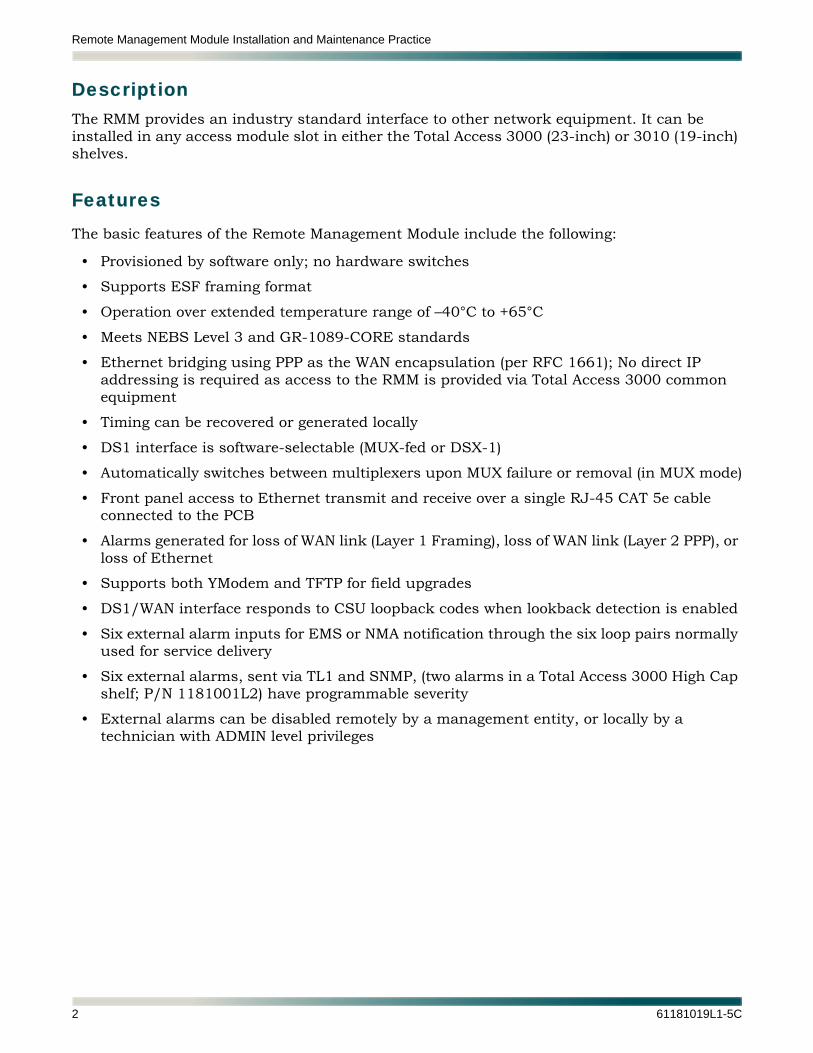
DescriptionThe RMM provides an industry standard interface to other network equipment. It can be installed in any access module slot in either the Total Access 3000 (23-inch) or 3010 (19-inch) shelves.
Features
The basic features of the Remote Management Module include the following:
• Provisioned by software only; no hardware switches
• Supports ESF framing format
• Operation over extended temperature range of –40°C to +65°C
• Meets NEBS Level 3 and GR-1089-CORE standards
• Ethernet bridging using PPP as the WAN encapsulation (per RFC 1661); No direct IP addressing is required as access to the RMM is provided via Total Access 3000 common equipment
• Timing can be recovered or generated locally
• DS1 interface is software-selectable (MUX-fed or DSX-1)
• Automatically switches between multiplexers upon MUX failure or removal (in MUX mode)
• Front panel access to Ethernet transmit and receive over a single RJ-45 CAT 5e cable connected to the PCB
• Alarms generated for loss of WAN link (Layer 1 Framing), loss of WAN link (Layer 2 PPP), or loss of Ethernet
• Supports both YModem and TFTP for field upgrades
• DS1/WAN interface responds to CSU loopback codes when lookback detection is enabled
• Six external alarm inputs for EMS or NMA notification through the six loop pairs normally used for service delivery
• Six external alarms, sent via TL1 and SNMP, (two alarms in a Total Access 3000 High Cap shelf; P/N 1181001L2) have programmable severity
• External alarms can be disabled remotely by a management entity, or locally by a technician with ADMIN level privileges
2 61181019L1-5C

General
ComplianceTable 1 shows the compliance codes for the Remote Management Module. The Remote Management Module is NRTL listed to the applicable UL standards. The Remote Management Module is to be installed in a restricted access location. This product is for use with intra-building wiring only.
This device complies with Part 15 of the FCC rules. Operation is subject to the following two conditions:
1. This device may not cause harmful interference.
2. This device must accept any interference received, including interference that may cause undesired operation.
Changes or modifications not expressly approved by ADTRAN could void the user’s authority to operate this equipment.
Shipping ContentsThe contents include the following items:
• Remote Management Module
• Remote Management Module Job Aid
Table 1. Compliance Codes
Code Input Output
Power Code (PC) A –
Telecommunication Code (TC) – X
Installation Code (IC) F C
61181019L1-5C 3

Remote Management Module Installation and Maintenance Practice
INSTALLATION
Inspect the Remote Management Module. If damaged, file a claim with the carrier then contact ADTRAN Customer Service. Refer to “Appendix A, Warranty” for further information. If possible, keep the original shipping container for returning the Remote Management Module for repair or for verification of shipping damage.
CAUTIONElectronic modules can be damaged by ESD. When handling mod-ules, wear an antistatic discharge wrist strap to prevent damage toelectronic components. Place modules in antistatic packing mate-rial when transporting or storing. When working on modules,always place them on an approved antistatic mat that is electricallygrounded.
The RMM plugs directly into the Total Access 3000 (23-inch) shelf or the Total Access 3010 (19-inch) shelf. Both are rack mounted chassis, with 28 access module slots on the Total Access 3000 and 22 access module slots on the Total Access 3010. Each access module contains the interfaces and appropriate circuitry to interface with the local loop.
C A U T I O N ! SUBJECT TO ELECTROSTATIC DAMAGE
OR DECREASE IN RELIABILITY.
HANDLING PRECAUTIONS REQUIRED.
4 61181019L1-5C

Installation
Instructions for Installing the Module
To install the Remote Management Module, perform the following steps:
1. If present, remove the Access Module Blank (P/N 1181953L1) from the appropriate access module slot of the Total Access 3000 chassis.
2. Pull the ejector tab on the bottom of the RMM into the down (open) position.
3. Plug the CAT 5e Ethernet cable into the RJ-45 connector located on the circuit board.
NOTES• Maximum CAT 5e cable length is 100 meters.• To connect the RMM directly to the Ethernet port on the SCU, an
Ethernet cross-over cable is required.
4. Route the cable up through the notch at the top edge of the front panel. Secure it with a small cable tie at the anchor slot, directly below the notch on the rear of the front panel.
5. Hold the RMM by the front panel while supporting the bottom edge of the module, and align the module edge with the guide groove in the chassis.
6. Firmly push the RMM into the slot. Simultaneous pressure at the top and bottom of the faceplate ensures a good seat of the module pins into the backplane connector.
If the chassis is operational, the module performs a self test at this point. When the self test is complete, the LEDs indicate the correct status of the module. Refer to “Front Panel LEDs” on page 6.
7. Push the ejector tab into the up (closed) position.
61181019L1-5C 5
Remote Management Module Installation and Maintenance Practice
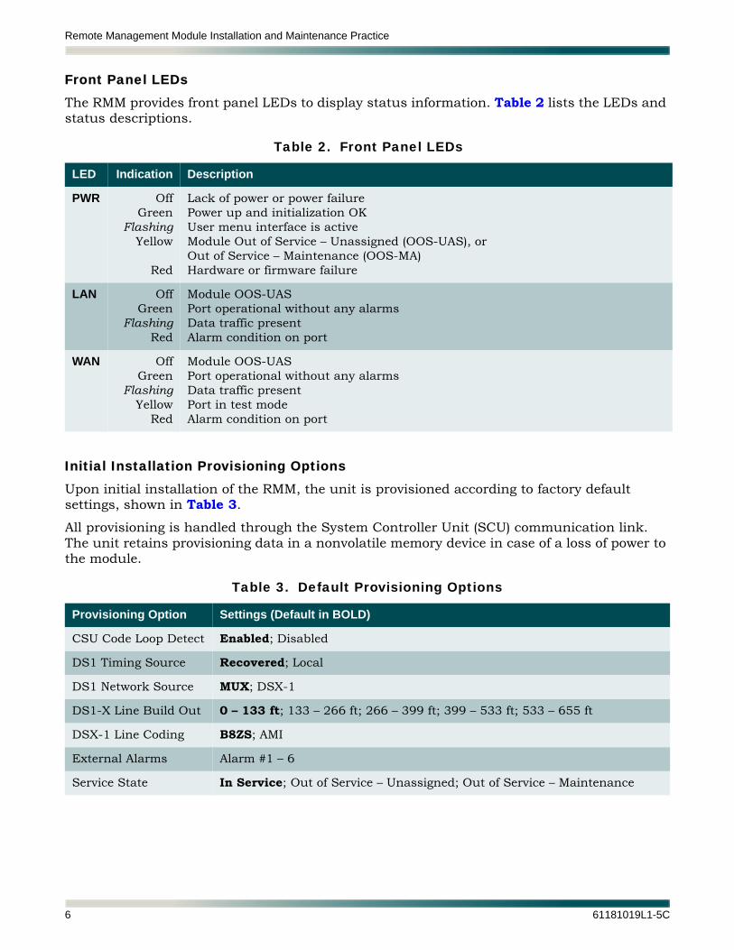
Front Panel LEDsThe RMM provides front panel LEDs to display status information. Table 2 lists the LEDs and status descriptions.
Initial Installation Provisioning OptionsUpon initial installation of the RMM, the unit is provisioned according to factory default settings, shown in Table 3.
All provisioning is handled through the System Controller Unit (SCU) communication link. The unit retains provisioning data in a nonvolatile memory device in case of a loss of power to the module.
Table 2. Front Panel LEDs
LED Indication Description
PWR OffGreen
FlashingYellow
Red
Lack of power or power failurePower up and initialization OKUser menu interface is activeModule Out of Service – Unassigned (OOS-UAS), orOut of Service – Maintenance (OOS-MA)Hardware or firmware failure
LAN OffGreen
FlashingRed
Module OOS-UASPort operational without any alarmsData traffic presentAlarm condition on port
WAN OffGreen
FlashingYellow
Red
Module OOS-UASPort operational without any alarmsData traffic presentPort in test modeAlarm condition on port
Table 3. Default Provisioning Options
Provisioning Option Settings (Default in BOLD)
CSU Code Loop Detect Enabled; Disabled
DS1 Timing Source Recovered; Local
DS1 Network Source MUX; DSX-1
DS1-X Line Build Out 0 – 133 ft; 133 – 266 ft; 266 – 399 ft; 399 – 533 ft; 533 – 655 ft
DSX-1 Line Coding B8ZS; AMI
External Alarms Alarm #1 – 6
Service State In Service; Out of Service – Unassigned; Out of Service – Maintenance
6 61181019L1-5C

Installation
WiringTable 4 lists the necessary RMM pinout information.
Note: Pins that are not connected have been left blank.
Table 4. RMM DIN Connections
Pin Connection Pin Connection Pin Connection
1A GND 1B FR_GND 1C –48VDCA
2A PWR_RET 2B FR_GND 2C –48VDCA
3A 3B 3C
4A ALM_4_B 4B ALM_4_A 4C ALM_2_B
5A ALM_3_B 5B ALM_3_A 5C ALM_2_A
6A 6B ALM_1_B 6C ALM_1_A
7A 7B 7C
8A 8B 8C
9A 9B SENSE 9C GROUP
10A HSMC_CLK_FRM_SCU 10B F_ALM 10C CARD
11A MAINT 11B IRQS 11C SC_BUS
12A IRQ 12B GND 12C GND
13A GND 13B MUXB_TC 13C MUXB_TD
14A MUXB_RD 14B GND 14C MUXB_RC
15A MUXA_RC 15B MUXA_TC 15C MUXA_TD
16A MUXA_RD 16B GND 16C GND
17A GND 17B 17C
18A 18B GND 18C
19A 19B 19C
20A 20B 20C
21A 21B GND 21C GND
22A GND 22B HSMC_FRM_SCU 22C HSMC_TWD_SCU
23A 23B 23C
24A 24B 24C
25A 25B 25C
26A 26B 26C
27A 27B ALM_5_B 27C ALM_5_A
28A 28B ALM_6_B 28C ALM_6_A
29A 29B PAIR_7_RING 29C PAIR_7_TIP
30A 30B PAIR_8_RING 30C PAIR_8_TIP
31A 31B 31C -48VDCB
32A 32B PWR_RET 32C -48VDCB
61181019L1-5C 7

Remote Management Module Installation and Maintenance Practice
OPERATIONThe RMM can occupy any access module slot and terminates a DS1 signal in the Total Access 3000/3010 system.
Power InterfaceThe RMM receives power from the Total Access 3000/3010 system.
SCU User/Supervisory InterfaceUser access to the RMM is through the SCU via the system bus present on the Total Access backplane. All menu items will be generated by the RMM. The SCU will initiate and control the transfer of commands and data to and from the unit. All provisioning and data reporting will take place over the communication bus.
Ethernet/LAN InterfaceThe Ethernet port automatically adjusts to accommodate 10 or 100 Mbps devices. Ethernet pinout transmits on pins 1 and 2 and receives on pins 3 and 6.
DS1/WAN InterfaceThe DS1/WAN interface supports ESF framing, recovered or local timing, line coding, line build out, and works at clock rates of 1.544 Mbps ±50 ppm. This interface responds to in-band CSU loopback codes only when loopback detection is enabled. Refer to “In-Band Loopbacks” on page 10 for more information.
The DS1/WAN port interfaces to a selected DS1 tributary within a DS3 or STS-1, depending on the installed multiplexer, when Network Source is set to MUX.
Setting Network Source to DSX-1 connects the DS1/WAN port to to an external DSX-1 interface on Pair 7 and 8.
• Pair 7 = T1/R1 (input)
• Pair 8 = T/R (output)
Refer to “DS1 Network Source” on page 16.
PPPThe PPP link is a protocol that operates over the physical DS1/WAN interface and encapsu-lates data traffic. The RMM PPP link consists of the LCP and BCP protocols and requires no authentication. If the physical DS1/WAN interface goes into an alarm state, the PPP link also goes into an alarm state.
8 61181019L1-5C

Operation
AlarmsAll active alarms are recorded in the RMM alarm display and are also reported to the SCU. The SCU maintains corresponding entries in its alarm log and also generates SNMP and TL1 trap notifications.
Major level alarms are generated by the WAN/DS1 interface upon Loss of Signal (LOS), Loss of Framing (LOF), receipt of Alarm Indication Signal (AIS), or receipt Remote Alarm Indication (RAI). Upon detection of LOS, LOF, or AIS the WAN/DS1 interface transmits RAI toward the MUX or DSX-1 interface (as selected).
A Major level alarm is generated by the LAN interface if the Ethernet link is down. A Major level alarm is generated if the PPP link carried by the WAN/DS1 interface goes down for any reason. An Alert level alarm is generated whenever the WAN/DS1 interface is placed into a loopback mode, either manually or via in-band CSU loop-up codes. Table 5 summarizes alarms generated by the RMM.
There are six external alarm inputs, consisting of two wires connectable through the Total Access 3000/3010 loop I/O connectors (Pairs 1 – 6). The external alarm input is associated with the “tip” connection which responds to the application or removal of –48 VDC. The “ring” connection supplies a low current source of –48 VDC so the external alarm can be controlled by shorting or opening the connection between the tip and ring through relay contacts. Each external alarm can be programmed to activate upon the closing or opening of the contacts.
Each of the six (two on the Total Access 3000 High Cap) Loop I/O connectors provides a single loop to each access module slot in the chassis. The “ring” side is associated with pins 1–28 on the connector, and the “tip” side is associated with pins 33–60. For example, ring and tip connections for slot 5 on a particular connector would be pins 5 and 37. External alarm inputs 1–6 are associated with pairs 1–6, respectively.
Table 5. Alarms
Type Condition Level Description
DS1 RAI DS1 receive RAI Major Yellow alarm received on DS1/WAN
DS1 AIS DS1 receive AIS Major All ones received on DS1/WAN
DS1 LOF DS1 loss of frame Major Loss of framing from on DS1/WAN
DS1 LOS DS1 loss of carrier Major 192 consecutive zeroes received on DS1/WAN
Ethernet Ethernet link down Major Loss of Ethernet connection
PPP PPP link down Major Loss of PPP connection
Loopbacks Activation of loopback mode Alert Loopback mode activated
61181019L1-5C 9
Remote Management Module Installation and Maintenance Practice
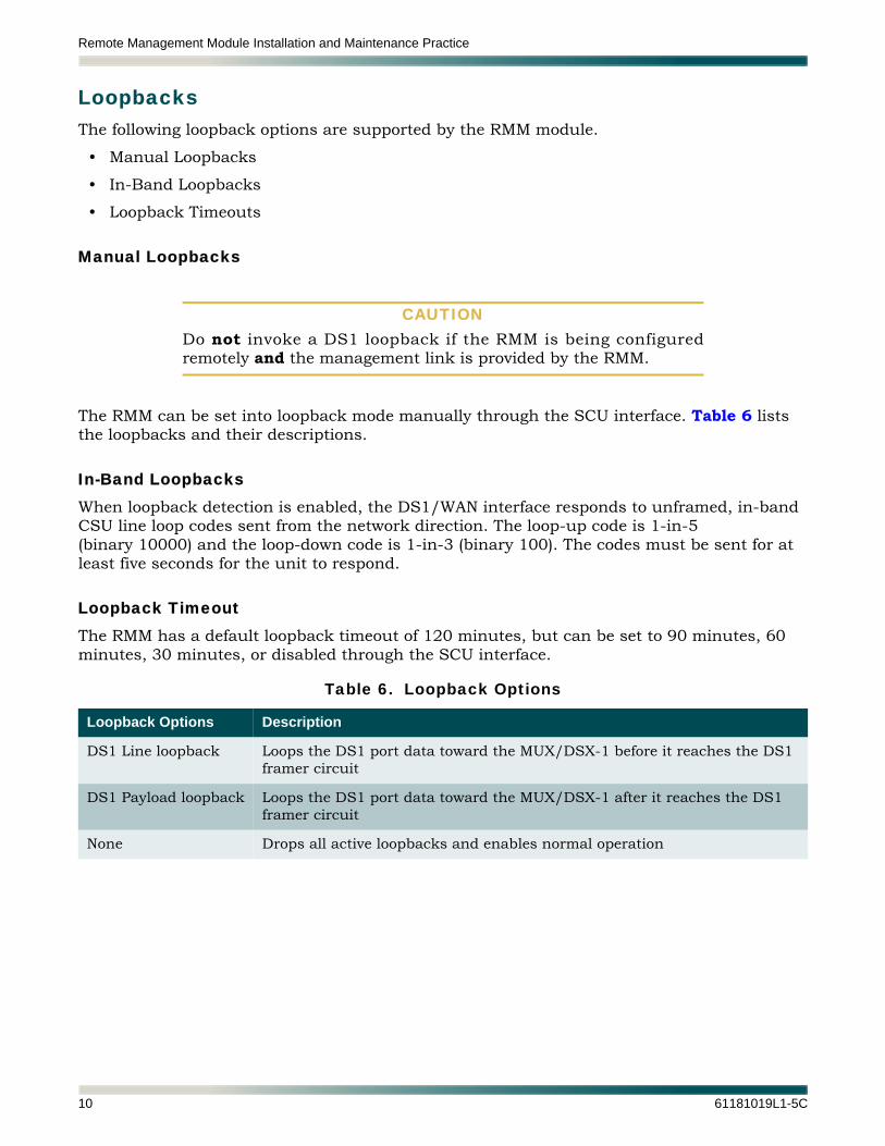
LoopbacksThe following loopback options are supported by the RMM module.
• Manual Loopbacks
• In-Band Loopbacks
• Loopback Timeouts
Manual Loopbacks
CAUTIONDo not invoke a DS1 loopback if the RMM is being configuredremotely and the management link is provided by the RMM.
The RMM can be set into loopback mode manually through the SCU interface. Table 6 lists the loopbacks and their descriptions.
In-Band LoopbacksWhen loopback detection is enabled, the DS1/WAN interface responds to unframed, in-band CSU line loop codes sent from the network direction. The loop-up code is 1-in-5(binary 10000) and the loop-down code is 1-in-3 (binary 100). The codes must be sent for at least five seconds for the unit to respond.
Loopback TimeoutThe RMM has a default loopback timeout of 120 minutes, but can be set to 90 minutes, 60 minutes, 30 minutes, or disabled through the SCU interface.
Table 6. Loopback Options
Loopback Options Description
DS1 Line loopback Loops the DS1 port data toward the MUX/DSX-1 before it reaches the DS1 framer circuit
DS1 Payload loopback Loops the DS1 port data toward the MUX/DSX-1 after it reaches the DS1 framer circuit
None Drops all active loopbacks and enables normal operation
10 61181019L1-5C
Menu Structure
MENU STRUCTUREThe SCU provides a menu system for the Total Access 3000 shelf. All system-related menus are controlled by the SCU. Each access module has its own user menu structure supported by the module.
The menu structure for the RMM is a layered menu tree. Each menu level consists of submenus and/or menu items. Some menu items are restricted to certain user accounts. The ADMIN account allows changes to all provisionable settings as well as network configuration settings that are not accessible to READWRITE and READONLY accounts. Figure 2 on page 12 illustrates the menu structure of the RMM.
Submenus are elements which move down to the next menu level. Menu items are elements used to make changes to the current SCU settings. There are two different types of menu items: read-only and read-write.
A read-only menu item displays information that can not be changed, such as the status of the RMM. A read-write menu item displays information that can be changed, such as DS1 framing.
NOTEMenus can be accessed during a TL1 session by typing menus;.
61181019L1-5C 11

Remote Management Module Installation and Maintenance Practice
Figure 2. Remote Management Module Menu Tree
1. ConfigurationMainMenu
Mai
n M
enu
2. Provisioning
1. CSU Loop Code Detect
4. Alarms
3. Status
5. Test
1. DS1 Testing
Unit Name:CLEI Code:Part Number:Serial Number:Product Revision:Software Revision:Boot Software Rev:MAC Address:
Execute <Y, N>
Execute <Y, N>
1. YMODEM Update
2. TFTP Update1. TFTP Filename
2. Start Transfer
1. In Service
2. Out of Service – Unassigned
3. Out of Service – Maintenance
1. Enabled
2. Disabled
DS1 Status
(Read-only)
(Read-only)
1. Reset Counters
1. Loopback
2. Loopback Timeout
PPP Link Status
1. Alarm #1
2. Alarm #2
3. Alarm #3
4. Alarm #4
5. Alarm #5
6. Alarm #6
1. 120 Minutes
2. 90 Minutes
3. 60 Minutes
4. 30 Minutes
5. Disabled
1. Name1. Enter New Name
Enter TFTP Filename
1. YES
2. NO
1. OPEN
2. CLOSED
1. MAJOR
2. MINOR
3. CRITICAL
4. ALERT
5. INFO
1. None
2. Payload
3. Line
1. WAN Status
2. Ethernet Status
3. External Alarm Status 1
8
9. Software Update
8. Restore Factory Defaults
7. Service State
6. External Alarms
2. Enable
3. Level
4. Detect
Status
6. Circuit ID
2. DS1 Timing Source
3. DS1 Network Source
4. DSX-1 Line Build Out
5. DSX-1 Line Coding
1. Recovered
2. Local
1. MUX
2. DSX-1
1. 0 – 133 ft
2. 133 – 266 ft
3. 266 – 399 ft
4. 399 – 533 ft
5. 533 – 655 ft
1. B8ZS
2. AMI
1. Start Transfer
2. Restart Card with Latest Code
3. Restart Card with Latest Code
12 61181019L1-5C
Menu Structure
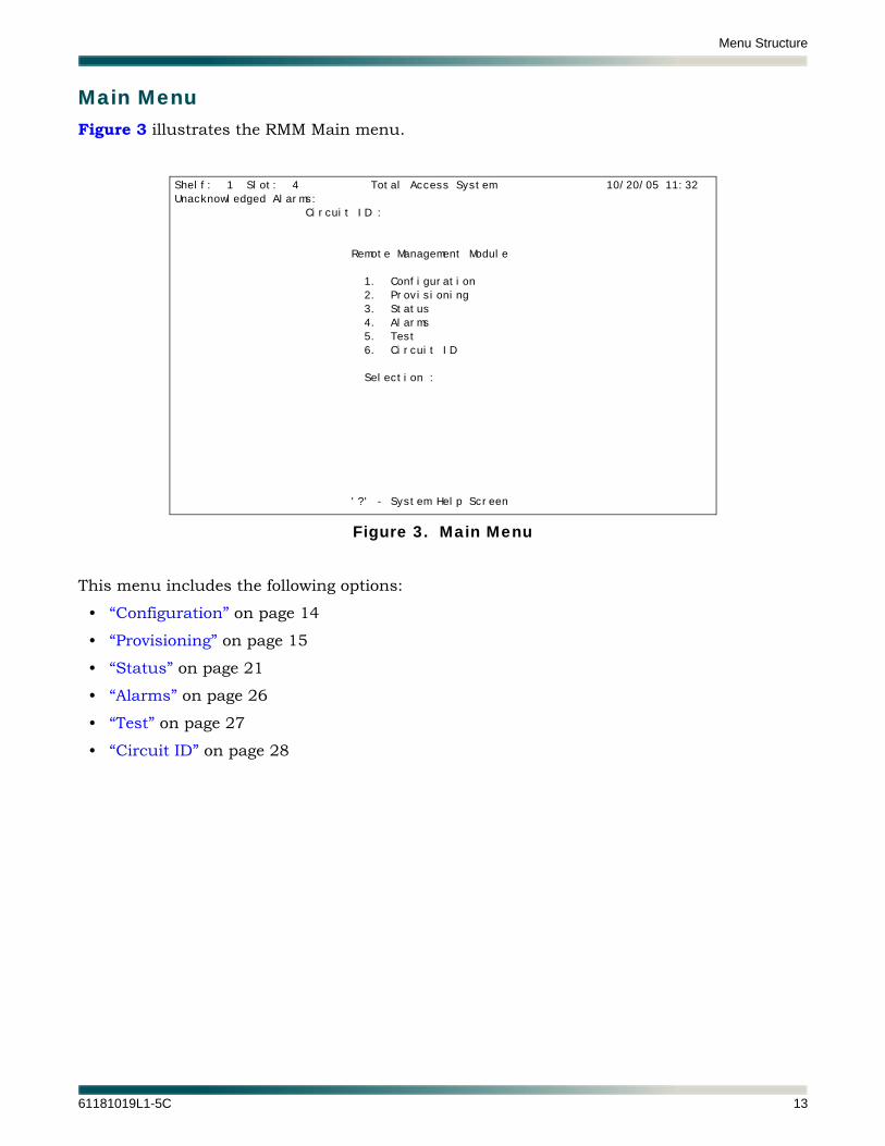
Main MenuFigure 3 illustrates the RMM Main menu.
Figure 3. Main Menu
This menu includes the following options:
• “Configuration” on page 14
• “Provisioning” on page 15
• “Status” on page 21
• “Alarms” on page 26
• “Test” on page 27
• “Circuit ID” on page 28
Shelf: 1 Slot: 4 Total Access System 10/20/05 11:32
Unacknowledged Alarms:
Circuit ID :
Remote Management Module
1. Configuration
2. Provisioning
3. Status
4. Alarms
5. Test
6. Circuit ID
Selection :
'?' - System Help Screen
61181019L1-5C 13
Remote Management Module Installation and Maintenance Practice
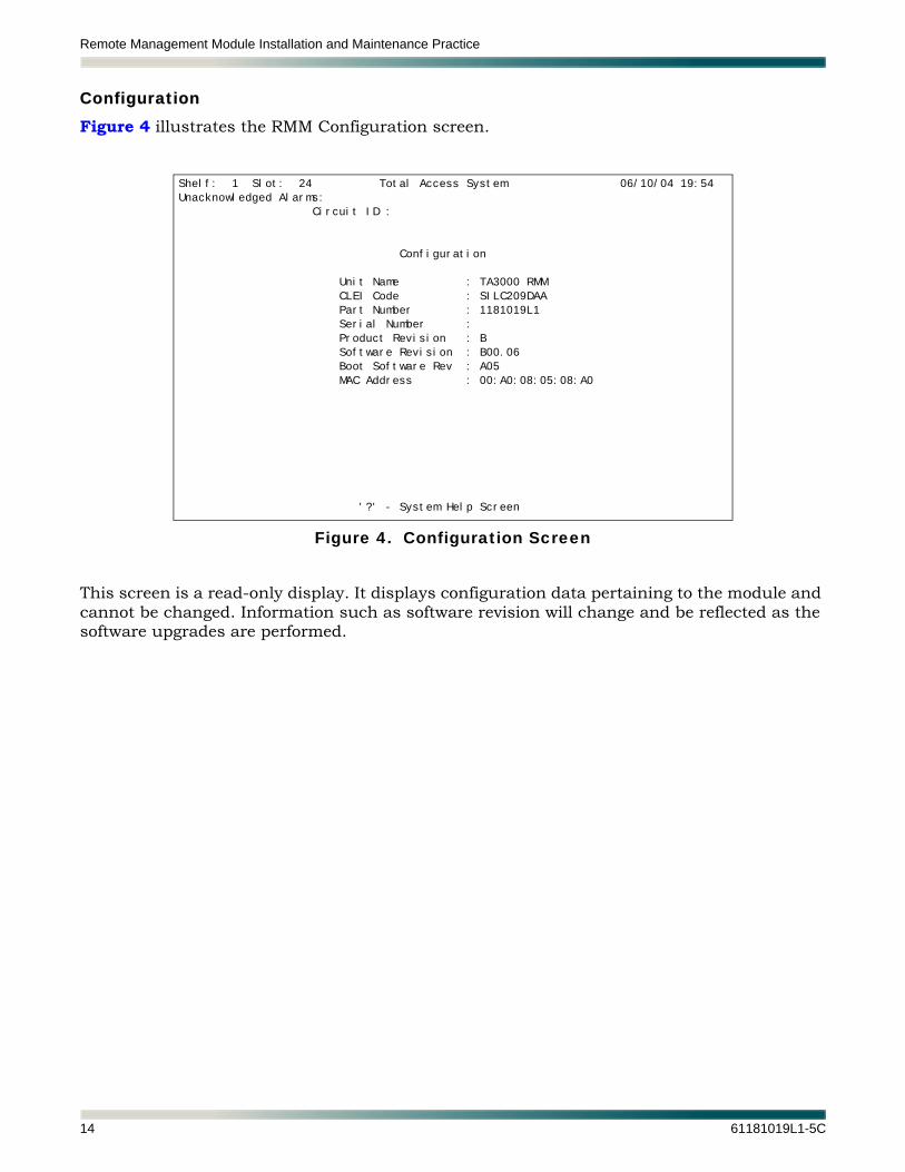
ConfigurationFigure 4 illustrates the RMM Configuration screen.
Figure 4. Configuration Screen
This screen is a read-only display. It displays configuration data pertaining to the module and cannot be changed. Information such as software revision will change and be reflected as the software upgrades are performed.
Shelf: 1 Slot: 24 Total Access System 06/10/04 19:54
Unacknowledged Alarms:
Circuit ID :
Configuration
Unit Name : TA3000 RMM
CLEI Code : SILC209DAA
Part Number : 1181019L1
Serial Number :
Product Revision : B
Software Revision : B00.06
Boot Software Rev : A05
MAC Address : 00:A0:08:05:08:A0
'?' - System Help Screen
14 61181019L1-5C

Menu Structure
ProvisioningFigure 5 illustrates the RMM Provisioning menu. Use this screen to make provisioning changes to module performance parameters. Provisioning changes can be made when the unit is in any of its three service states.
CAUTIONSome provisioning changes can momentarily disrupt traffic. If aselected change has the potential to be service affecting, a systemprompt for confirmation is displayed.
Figure 5. Provisioning Menu
The Provisioning menu includes the following options:
• “CSU Code Loop Detect” on page 16
• “DS1 Timing Source” on page 16
• “DS1 Network Source” on page 16
• “DSX-1 Line Build Out” on page 16
• “DSX-1 Line Coding” on page 16
• “External Alarms” on page 17
• “Service State” on page 17
• “Restore Factory Defaults” on page 17
• “Software Update” on page 18
Shelf: 1 Slot: 4 Total Access System 10/20/05 11:33
Unacknowledged Alarms:
Circuit ID :
RMM Provisioning
1. CSU Loop Code Detect : Enabled
2. DS1 Timing Source : Recovered
3. DS1 Network Source : MUX
4. DSX-1 Line Build Out : 0 - 133 ft
5. DSX-1 Line Coding : B8ZS
6. External Alarms
7. Service State : In Service
8. Restore Factory Defaults
9. Software Update
Selection :
'?' - System Help Screen
61181019L1-5C 15
Remote Management Module Installation and Maintenance Practice
CSU Code Loop Detect
CSU Code Loop Detect provisions if the unit responds to CSU loopback codes.
• Enabled: Unit responds to CSU loopback codes
• Disabled: Unit does not respond to CSU loopback codes
DS1 Timing Source
DS1 Timing supports the following two options:
• Local
• Recovered
DS1 Network Source
DS1 Network Source supports the following two options:
• MUX
• DSX-1
DSX-1 Line Build Out
DSX-1 Line Build Out specifies the line length for the DSX-1. It supports the following options:
• 0 – 133 feet
• 133 – 266 feet
• 266 – 399 feet
• 399 – 533 feet
• 533 – 655 feet
NOTEThis option has no effect if DS1 Network Source is set to MUX.
DSX-1 Line Coding
DSX-1 Line Coding supports the following two options:
• B8ZS
• AMI
NOTEThis option has no effect if DS1 Network Source is set to MUX.
16 61181019L1-5C

Menu Structure
External Alarms
External Alarms lists Alarm #1 – #6. Select an alarm to provision it individually. The following options are supported for each of the alarm inputs:
• Name: (Text string up to 40 characters long)
• Enable: (Yes, No)
• Level: (Critical, Major, Minor, Alert, Info)
• Detect: (Closed or Open connection on alarm input)
An additional Status field indicates current alarm state (Active or Inactive).
Service State
Service State options include the following:
CAUTIONDo not change the service state to Out of Service – Unassigned ifconfiguring the RMM remotely and the management link to theremote SCU runs through the RMM.
• In Service (data transfer and alarms are enabled)
• Out of Service – Maintenance (still passes data, but alarms are suppressed)
• Out of Service – Unassigned (data transfer and alarms are disabled)
Restore Factory Defaults
Restore Factory Defaults resets all provisioned options to default settings.
Provisioning options are outlined in Table 3 on page 6.
61181019L1-5C 17

Remote Management Module Installation and Maintenance Practice
Software Update
Use Software Update to download new software to the RMM, as available. Software Update supports two transfer protocols: TFTP or YModem.
YModem UpdateTo update software via YModem:
1. From the Software Upgrade menu, select YModem Update, and press ENTER.
The YModem Software Update screen (Figure 6) appears.
Figure 6. YModem Software Update
2. Select Start Transfer, and press ENTER.
A series of Cs begins to appear at the Selection: prompt, indicating the RMM is awaiting YModem file transfer.
3. Use the desired YModem application to send the required binary file, and wait for the transfer to complete.
Shelf: 1 Slot: 4 Total Access System 10/21/05 10:15
Unacknowledged Alarms:
Circuit ID :
YMODEM Software Update
App Software Rev : B00.06
App Code Chksum : 1B29DD9D
Build Date : Mon Oct 03 14:07:55 2005
Boot Software Rev : A05
Boot Code Chksum : 586C
Download Status : Idle
This utility programs the RMM. The VT100 terminal emulation
program used must support YMODEM file transfers and have access
to the software binary file (*.bin).
1. Start Transfer
Selection:
'?' - System Help Screen
18 61181019L1-5C
Menu Structure
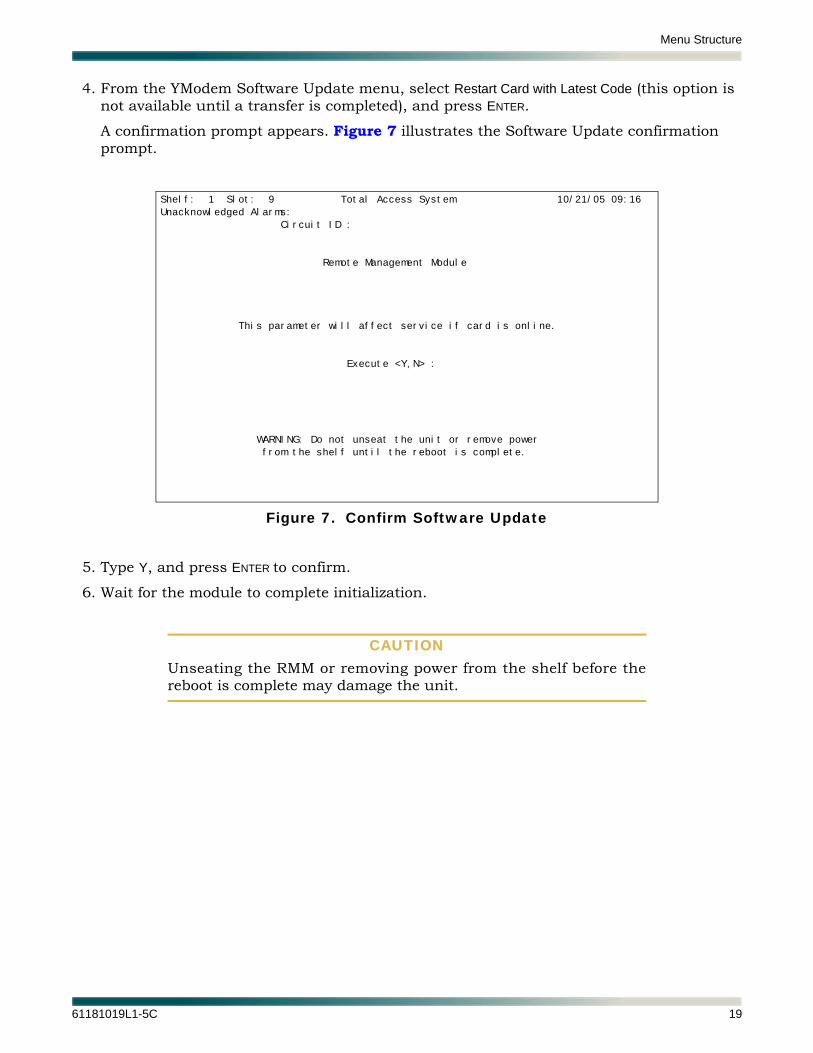
4. From the YModem Software Update menu, select Restart Card with Latest Code (this option is not available until a transfer is completed), and press ENTER.
A confirmation prompt appears. Figure 7 illustrates the Software Update confirmation prompt.
Figure 7. Confirm Software Update
5. Type Y, and press ENTER to confirm.
6. Wait for the module to complete initialization.
CAUTIONUnseating the RMM or removing power from the shelf before thereboot is complete may damage the unit.
Shelf: 1 Slot: 9 Total Access System 10/21/05 09:16
Unacknowledged Alarms:
Circuit ID :
Remote Management Module
This parameter will affect service if card is online.
Execute <Y,N> :
WARNING: Do not unseat the unit or remove power
from the shelf until the reboot is complete.
61181019L1-5C 19
Remote Management Module Installation and Maintenance Practice
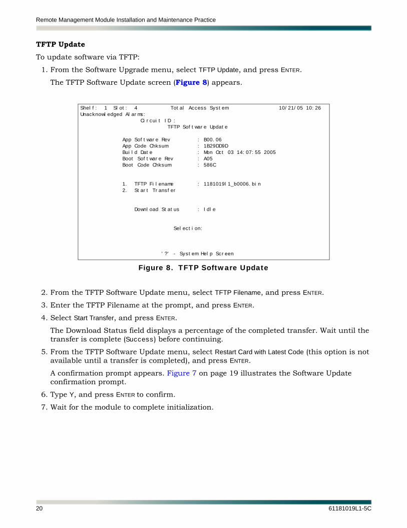
TFTP UpdateTo update software via TFTP:
1. From the Software Upgrade menu, select TFTP Update, and press ENTER.
The TFTP Software Update screen (Figure 8) appears.
Figure 8. TFTP Software Update
2. From the TFTP Software Update menu, select TFTP Filename, and press ENTER.
3. Enter the TFTP Filename at the prompt, and press ENTER.
4. Select Start Transfer, and press ENTER.
The Download Status field displays a percentage of the completed transfer. Wait until the transfer is complete (Success) before continuing.
5. From the TFTP Software Update menu, select Restart Card with Latest Code (this option is not available until a transfer is completed), and press ENTER.
A confirmation prompt appears. Figure 7 on page 19 illustrates the Software Update confirmation prompt.
6. Type Y, and press ENTER to confirm.
7. Wait for the module to complete initialization.
Shelf: 1 Slot: 4 Total Access System 10/21/05 10:26
Unacknowledged Alarms:
Circuit ID :
TFTP Software Update
App Software Rev : B00.06
App Code Chksum : 1B29DD9D
Build Date : Mon Oct 03 14:07:55 2005
Boot Software Rev : A05
Boot Code Chksum : 586C
1. TFTP Filename : 1181019l1_b0006.bin
2. Start Transfer
Download Status : Idle
Selection:
'?' - System Help Screen
20 61181019L1-5C

Menu Structure
StatusFigure 9 illustrates the RMM Status menu. The screen is read-only, displaying module status information.
Figure 9. Status Menu
The options available in the Status menu include the following:
• “WAN Status” on page 22
• “Ethernet Status” on page 24
• “External Alarm Status” on page 25
Shelf: 1 Slot: 4 Total Access System 10/20/05 13:32
Unacknowledged Alarms:
Circuit ID :
RMM Status
1. WAN Status
2. Ethernet Status
3. External Alarm Status
Selection :
'?' - System Help Screen
61181019L1-5C 21

Remote Management Module Installation and Maintenance Practice
WAN Status
WAN Status (Figure 10) reports DS1 interface status, including Framing, Alarm, Loopback, and Protocol states.
Figure 10. WAN Status Screen
This screen includes a single selectable option, Reset Counters, to clear accumulated data.
Table 7 on page 23 lists the definitions for the PPP Link Status states.
Shelf: 1 Slot: 9 Total Access System 12/16/05 11:54
Unacknowledged Alarms:
Circuit ID :
WAN Status
DS1 Status
Line Status : Normal
CSU Loop Detect : Enabled
Timing Source : Local
Network Source : DSX-1
Line Buildout : 0 - 133 ft
Line Coding : B8ZS
Framing : ESF
Loopbacks : None
PPP Link Status
Link (LCP) Status : Open
Bridge (BCP) Status : Open
Octets Sent/Received : 43445/672101
Received Frame Errors : 0
1. Reset Counters
Selection :
'?' - System Help Screen
22 61181019L1-5C

Menu Structure
The Typical Status states appear under normal operational circumstances. Negotiation states normally occur in rapid succession during the negotiation phase and may only be briefly visible. Link Closure states occur when the connection is terminated, and only appear if the PPP link is incorrectly configured on the far end.
1. If Status reflects a Negotiation State, this indicates the DS1 is working, and the LCP/BCP layers are attempting to negotiate a connection with the far end. If the unit ‘sticks’ in one of the negotiation states for a long time, there may be a PPP configuration problem with the far end (e.g., PPP Authentication could be set to something other than ‘None’).
2. If Status reflects a Link Closure state, this indicates the DS1 is working, but the LCP or BCP control layers are unable to negotiate a connection with the far end successfully. The PPP configuration should be checked on the far end. Make sure that LCP and BCP are enabled and that PPP Authentication is set to ‘None’.
Table 7. PPP LCP/BCP Status Definitions
Status Definition
Typical States
Initial DS1 layer is unavailable (down); Check for DS1 alarms
Starting DS1 layer is unavailable (down), waiting to re-establish LCP/BCP link;Check for DS1 alarms
Open LCP/BCP link is up and operating properly; No further action required
Negotiation States1
REQ Sent RMM is attempting to configure the LCP/BCP link with the far end
ACK Received Far end has acknowledged the configure request
ACK Sent RMM is waiting for a configure acknowledgement from the far end
Link Closure States2
Closed LCP/BCP link is in contact with the far end, but no Open event has occurred
Stopped LCP/BCP link is in contact with the far end, but no Down event has occurred
Closing An attempt is being made to terminate the LCP/BCP link
Stopping An attempt is being made to terminate the LCP/BCP link
61181019L1-5C 23
Remote Management Module Installation and Maintenance Practice
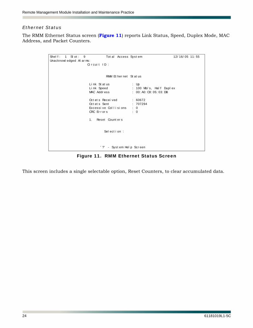
Ethernet Status
The RMM Ethernet Status screen (Figure 11) reports Link Status, Speed, Duplex Mode, MAC Address, and Packet Counters.
Figure 11. RMM Ethernet Status Screen
This screen includes a single selectable option, Reset Counters, to clear accumulated data.
Shelf: 1 Slot: 9 Total Access System 12/16/05 11:55
Unacknowledged Alarms:
Circuit ID :
RMM Ethernet Status
Link Status : Up
Link Speed : 100 Mb/s, Half Duplex
MAC Address : 00:A0:C8:05:03:DB
Octets Received : 60672
Octets Sent : 707294
Excessive Collisions : 0
CRC Errors : 0
1. Reset Counters
Selection :
'?' - System Help Screen
24 61181019L1-5C

Menu Structure
External Alarm Status
The RMM External Alarm Status screen (Figure 12) reports External Alarm Input State, Level, and Enable status.
Figure 12. RMM External Alarm Status Screen
Shelf: 1 Slot: 9 Total Access System 12/16/05 11:58
Unacknowledged Alarms:
Circuit ID :
RMM External Alarm Status
Name Enable Level Detect Status
1) ........................................ NO INFO CLOSED Inactive
2) ........................................ NO INFO CLOSED Inactive
3) ........................................ NO INFO CLOSED Inactive
4) ........................................ NO INFO CLOSED Inactive
5) ........................................ NO INFO CLOSED Inactive
6) ........................................ NO INFO CLOSED Inactive
'?' - System Help Screen
61181019L1-5C 25
Remote Management Module Installation and Maintenance Practice
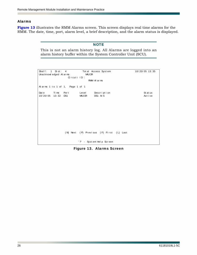
AlarmsFigure 13 illustrates the RMM Alarms screen. This screen displays real time alarms for the RMM. The date, time, port, alarm level, a brief description, and the alarm status is displayed.
NOTEThis is not an alarm history log. All Alarms are logged into analarm history buffer within the System Controller Unit (SCU).
Figure 13. Alarms Screen
Shelf: 1 Slot: 4 Total Access System 10/20/05 13:35
Unacknowledged Alarms: MAJOR
Circuit ID :
RMM Alarms
Alarms 1 to 1 of 1, Page 1 of 1
Date Time Port Level Description Status
10/20/05 13:32 DS1 MAJOR DS1 AIS Active
(N) Next (P) Previous (F) First (L) Last
'?' - System Help Screen
26 61181019L1-5C

Menu Structure
TestFigure 14 illustrates the RMM Test menu. Select DS1 Testing to perform various loopback tests at the DS1 level. The loopback options are outlined in Table 6 on page 10.
Figure 14. Test Menu
Shelf: 1 Slot: 4 Total Access System 10/20/05 13:37
Unacknowledged Alarms:
Circuit ID :
RMM Test
1. DS1 Testing
Selection :
'?' - System Help Screen
61181019L1-5C 27

Remote Management Module Installation and Maintenance Practice
Circuit IDFigure 15 illustrates the Circuit ID assignment screen. The Circuit ID is a user-definable string that can distinguish one circuit from another, by naming each circuit according to a designated internal naming convention. The Circuit ID has a maximum length of 30 characters.
The Circuit ID, once entered, appears in the header of each screen.
Figure 15. Circuit ID Screen
To remove a Circuit ID, leaving the field blank in the headers, press the SPACEBAR in the Circuit ID field, and then press ENTER.
MAINTENANCEThe Total Access 3000 Remote Management Module does not require routine maintenance for normal operation.
ADTRAN does not recommend that repairs be attempted in the field. Repair services may be obtained by returning the defective unit to ADTRAN. Refer to “Appendix A, Warranty” for further information.
Shelf: 1 Slot: 4 Total Access System 10/20/05 16:09
Unacknowledged Alarms:
Circuit ID :
Circuit ID
Circuit ID :
Enter New Circuit ID :
'?' - System Help Screen
28 61181019L1-5C

Specifications
SPECIFICATIONSSpecifications for the Total Access 3000 Remote Management Module are detailed in Table 8.
Table 8. Remote Management Module Specifications
Specification Description
Mechanical
Size:Weight:
Mounting:
5.5 inches H × 10.5 inches D × 0.6 inches W0.35 pound (5.6 ounces)Total Access 3000 shelf; Total Access 3010 shelf
Power
Input Voltage Range:
Maximum Current:Total Power Dissipation:
–42 VDC minimum–56 VDC maximum–48 VDC nominal52 mA at –42 VDC< 3 Watts
Compliance
UL 1950NEBS Level 3
(GR-1089 Intra-building on Ethernet, GR-63)(GR-1089 Intra-building on DSX-1, GR-63)
SBC TP76200MD
Environmental
Operating Temperature:Storage Temperature:
Relative Humidity:
–40°C to +65°C–40°C to +85°C95 percent maximum @ 50°C, noncondensing
61181019L1-5C 29

Remote Management Module Installation and Maintenance Practice
This page is intentionally blank.
30 61181019L1-5C

Appendix AWarranty
WARRANTY AND CUSTOMER SERVICEADTRAN will replace or repair this product within the warranty period if it does not meet its published specifications or fails while in service. Warranty information can be found at www.adtran.com/warranty.
Refer to the following subsections for sales, support, Customer and Product Service (CAPS) requests, or further information.
ADTRAN SalesPricing/Availability:
800-827-0807
ADTRAN Technical SupportPre-Sales Applications/Post-Sales Technical Assistance:
800-726-8663
Standard hours: Monday - Friday, 7 a.m. - 7 p.m. CSTEmergency hours: 7 days/week, 24 hours/day
ADTRAN Repair/CAPSReturn for Repair/Upgrade:
(256) 963-8722
Repair and Return AddressContact CAPS prior to returning equipment to ADTRAN.
ADTRAN, Inc.CAPS Department901 Explorer BoulevardHuntsville, Alabama 35806-2807
61181019L1-5C A-1

Carrier Networks Division901 Explorer Blvd.
Huntsville, AL 35806
®


![Remote Control Manual Curve Tracer CS-3000 Series1].pdf · Remote Control Manual Curve Tracer CS-3000 Series . i Introduction Thank you for purchasing this Iwatsu’s instrument.](https://static.fdocuments.in/doc/165x107/60633b3ad981ce04802d3c1f/remote-control-manual-curve-tracer-cs-3000-1pdf-remote-control-manual-curve.jpg)