Toshiba Estia - installatørvejledning
84
E10-371 Engineering Data Book Air to Water Heat Pump Hydro Unit HWS-803XWHM3-E HWS-803XWHT6-E HWS-803XWHD6-E HWS-803XWHT9-E HWS-1403XWHM3-E HWS-1403XWHT6-E HWS-1403XWHD6-E HWS-1403XWHT9-E Outdoor Unit HWS-803H-E HWS-1103H-E HWS-1403H-E HWS-1103H8-E HWS-1403H8-E HWS-1603H8-E HWS-1103H8R-E HWS-1403H8R-E HWS-1603H8R-E Hot Water Cylinder HWS-1501CSHM3-E HWS-2101CSHM3-E HWS-3001CSHM3-E HWS-1501CSHM3-UK HWS-2101CSHM3-UK HWS-3001CSHM3-UK
description
Toshiba Estia luft til vand varmepumpe - vejledning for VVS og pumpe montører
Transcript of Toshiba Estia - installatørvejledning
E10-371
Engineering Data BookAir to Water Heat Pump
Hydro Unit
HWS-803XWHM3-E
HWS-803XWHT6-E
HWS-803XWHD6-E
HWS-803XWHT9-E
HWS-1403XWHM3-E
HWS-1403XWHT6-E
HWS-1403XWHD6-E
HWS-1403XWHT9-E
Outdoor Unit
HWS-803H-E
HWS-1103H-E
HWS-1403H-E
HWS-1103H8-E
HWS-1403H8-E
HWS-1603H8-E
HWS-1103H8R-E
HWS-1403H8R-E
HWS-1603H8R-E
Hot Water Cylinder
HWS-1501CSHM3-E
HWS-2101CSHM3-E
HWS-3001CSHM3-E
HWS-1501CSHM3-UK
HWS-2101CSHM3-UK
HWS-3001CSHM3-UK

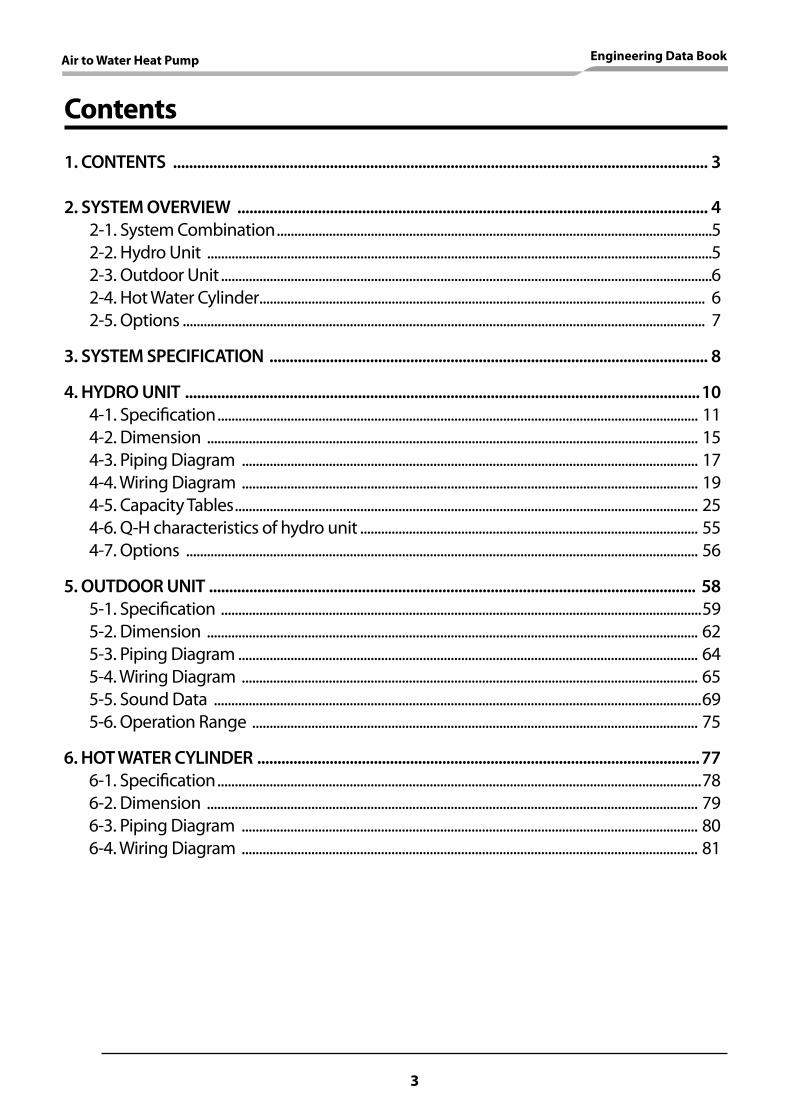
Contents
1. CONTENTS ..................................................................................................................................... 3
2. SYSTEM OVERVIEW ..................................................................................................................... 4 2-1. System Combination .............................................................................................................................5 2-2. Hydro Unit .................................................................................................................................................5 2-3. Outdoor Unit .............................................................................................................................................6 2-4. Hot Water Cylinder ................................................................................................................................ 6 2-5. Options ...................................................................................................................................................... 7
3. SYSTEM SPECIFICATION ............................................................................................................. 8
4. HYDRO UNIT ................................................................................................................................10 4-1. Specification .......................................................................................................................................... 11 4-2. Dimension ............................................................................................................................................. 15 4-3. Piping Diagram ................................................................................................................................... 17 4-4. Wiring Diagram ................................................................................................................................... 19 4-5. Capacity Tables ..................................................................................................................................... 25 4-6. Q-H characteristics of hydro unit ................................................................................................. 55 4-7. Options ................................................................................................................................................... 56
5. OUTDOOR UNIT ......................................................................................................................... 58 5-1. Specification ..........................................................................................................................................59 5-2. Dimension ............................................................................................................................................. 62 5-3. Piping Diagram .................................................................................................................................... 64 5-4. Wiring Diagram ................................................................................................................................... 65 5-5. Sound Data ............................................................................................................................................69 5-6. Operation Range ................................................................................................................................ 75
6. HOT WATER CYLINDER ..............................................................................................................77 6-1. Specification ...........................................................................................................................................78 6-2. Dimension ............................................................................................................................................. 79 6-3. Piping Diagram ................................................................................................................................... 80 6-4. Wiring Diagram ................................................................................................................................... 81
Air to Water Heat Pump Engineering Data Book
3

2. SYSTEM OVERVIEW
4
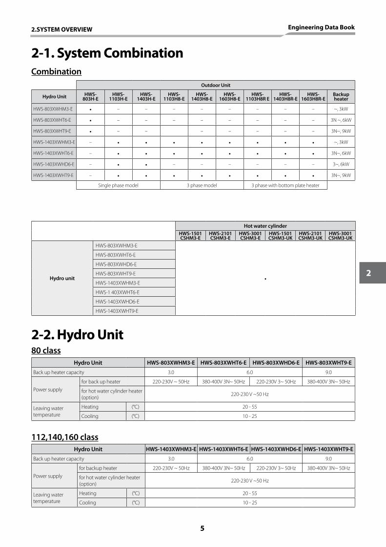
2-1. System CombinationCombination
2-2. Hydro Unit
Hydro Unit HWS-803XWHM3-E HWS-803XWHT6-E HWS-803XWHD6-E HWS-803XWHT9-E
Back up heater capacity 3.0 6.0 9.0
Power supplyfor back up heater 220-230V ~ 50Hz 380-400V 3N~ 50Hz 220-230V 3~ 50Hz 380-400V 3N~ 50Hz
for hot water cylinder heater (option) 220-230 V ~50 Hz
Leaving water temperature
Heating (°C) 20 - 55
Cooling (°C) 10 - 25
Hydro Unit HWS-1403XWHM3-E HWS-1403XWHT6-E HWS-1403XWHD6-E HWS-1403XWHT9-E
Back up heater capacity 3.0 6.0 9.0
Power supplyfor backup heater 220-230V ~ 50Hz 380-400V 3N~ 50Hz 220-230V 3~ 50Hz 380-400V 3N~ 50Hz
for hot water cylinder heater (option) 220-230 V ~50 Hz
Leaving water temperature
Heating (°C) 20 - 55
Cooling (°C) 10 - 25
Hot water cylinderHWS-1501CSHM3-E
HWS-2101CSHM3-E
HWS-3001CSHM3-E
HWS-1501CSHM3-UK
HWS-2101CSHM3-UK
HWS-3001CSHM3-UK
Hydro unit
HWS-803XWHM3-E
•
HWS-803XWHT6-E
HWS-803XWHD6-E
HWS-803XWHT9-E
HWS-1403XWHM3-E
HWS-1 403XWHT6-E
HWS-1403XWHD6-E
HWS-1403XWHT9-E
Outdoor Unit
Hydro Unit HWS- 803H-E
HWS-1103H-E
HWS-1403H-E
HWS-1103H8-E
HWS-1403H8-E
HWS-1603H8-E
HWS- 1103H8R E
HWS- 1403H8R-E
HWS-1603H8R-E
Backup heater
HWS-803XWHM3-E • – – – – – – – – ~, 3kW
HWS-803XWHT6-E • – – – – – – – – 3N ~, 6kW
HWS-803XWHT9-E • – – – – – – – 3N~, 9kW
HWS-1403XWHM3-E – • • • • • • • • ~, 3kW
HWS-1403XWHT6-E – • • • • • • • • 3N~, 6kW
HWS-1403XWHD6-E – • • – – – – – – 3~, 6kW
HWS-1403XWHT9-E – • • • • • • • • 3N~, 9kW
Single phase model 3 phase model 3 phase with bottom plate heater
80 class
112,140,160 class
2.SYSTEM OVERVIEW Engineering Data Book
5
2
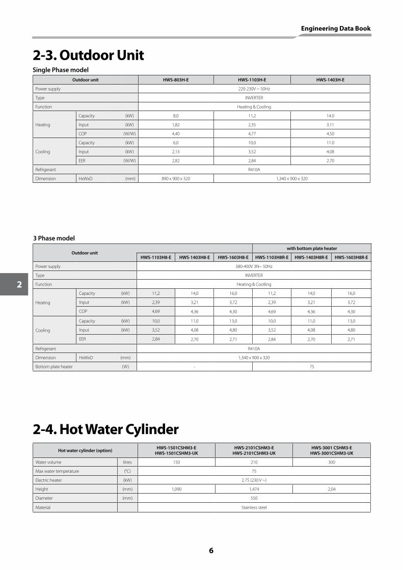
2-3. Outdoor Unit
2-4. Hot Water Cylinder
Outdoor unit HWS-803H-E HWS-1103H-E HWS-1403H-E
Power supply 220-230V ~ 50Hz
Type INVERTER
Function Heating & Cooling
Heating
Capacity (kW) 8,0 11,2 14.0
Input (kW) 1,82 2,35 3.11
COP (W/W) 4,40 4,77 4.50
Cooling
Capacity (kW) 6,0 10,0 11.0
Input (kW) 2,13 3,52 4.08
EER (W/W) 2,82 2,84 2.70
Refrigerant R410A
Dimension HxWxD (mm) 890 x 900 x 320 1,340 x 900 x 320
Outdoor unitwith bottom plate heater
HWS-1103H8-E HWS-1403H8-E HWS-1603H8-E HWS-1103H8R-E HWS-1403H8R-E HWS-1603H8R-E
Power supply 380-400V 3N~ 50Hz
Type INVERTER
Function Heating & Coolling
Heating
Capacity (kW) 11,2 14,0 16,0 11,2 14,0 16,0
Input (kW) 2,39 3,21 3,72 2,39 3,21 3,72
COP 4,69 4,36 4,30 4,69 4,36 4,30
Cooling
Capacity (kW) 10,0 11,0 13,0 10,0 11,0 13,0
Input (kW) 3,52 4,08 4,80 3,52 4,08 4,80
EER 2,84 2,70 2,71 2,84 2,70 2,71
Refrigerant R410A
Dimension HxWxD (mm) 1,340 x 900 x 320
Bottom plate heater (W) - 75
Hot water cylinder (option) HWS-1501CSHM3-EHWS-1501CSHM3-UK
HWS-2101CSHM3-EHWS-2101CSHM3-UK
HWS-3001 CSHM3-EHWS-3001CSHM3-UK
Water volume litres 150 210 300
Max water temperature (°C) 75
Electric heater (kW) 2.75 (230 V ~)
Height (mm) 1,090 1,474 2,04
Diameter (mm) 550
Material Stainless steel
Single Phase model
3 Phase model
Engineering Data Book
6
2
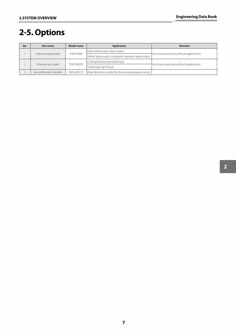
2-5. OptionsNo. Part name Model name Application Remarks
1 External output board TCB-PCIN3EBoiler-linked output, Alarm output
Up to two boards (according to applications)Defrost signal output, compressor operation signal output
2 External input board TCB-PCMO3ECooling/heating thermostat input
Up to two boards (according to applications)Forced-stop signal input
3 Second Remote Controller HWS-AMS11E Wider Remote Controller for Room air temperature control
2.SYSTEM OVERVIEW Engineering Data Book
7
2

3. SYSTEM SPECIFICATION
8
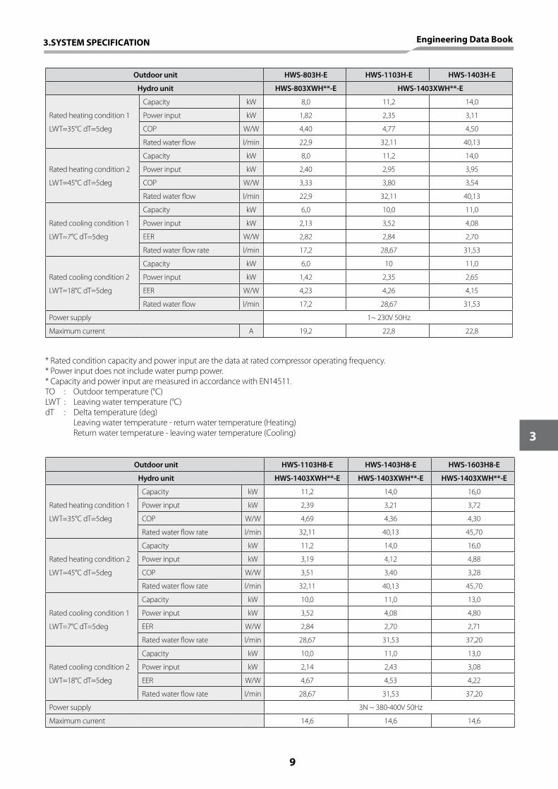
* Rated condition capacity and power input are the data at rated compressor operating frequency.* Power input does not include water pump power.* Capacity and power input are measured in accordance with EN14511.TO : Outdoor temperature (°C)LWT : Leaving water temperature (°C)dT : Delta temperature (deg) Leaving water temperature - return water temperature (Heating) Return water temperature - leaving water temperature (Cooling)
Outdoor unit HWS-803H-E HWS-1103H-E HWS-1403H-E
Hydro unit HWS-803XWH**-E HWS-1403XWH**-E
Rated heating condition 1
Capacity kW 8,0 11,2 14,0
Power input kW 1,82 2,35 3,11
LWT=35°C dT=5deg COP W/W 4,40 4,77 4,50
Rated water flow l/min 22,9 32,11 40,13
Rated heating condition 2
Capacity kW 8,0 11,2 14,0
Power input kW 2,40 2,95 3,95
LWT=45°C dT=5deg COP W/W 3,33 3,80 3,54
Rated water flow l/min 22,9 32,11 40,13
Rated cooling condition 1
Capacity kW 6,0 10,0 11,0
Power input kW 2,13 3,52 4,08
LWT=7°C dT=5deg EER W/W 2,82 2,84 2,70
Rated water flow rate l/min 17,2 28,67 31,53
Rated cooling condition 2
Capacity kW 6,0 10 11,0
Power input kW 1,42 2,35 2,65
LWT=18°C dT=5deg EER W/W 4,23 4,26 4,15
Rated water flow l/min 17,2 28,67 31,53
Power supply 1~ 230V 50Hz
Maximum current A 19,2 22,8 22,8
Outdoor unit HWS-1103H8-E HWS-1403H8-E HWS-1603H8-E
Hydro unit HWS-1403XWH**-E HWS-1403XWH**-E HWS-1403XWH**-E
Rated heating condition 1
Capacity kW 11,2 14,0 16,0
Power input kW 2,39 3,21 3,72
LWT=35°C dT=5deg COP W/W 4,69 4,36 4,30
Rated water flow rate l/min 32,11 40,13 45,70
Rated heating condition 2
Capacity kW 11,2 14,0 16,0
Power input kW 3,19 4,12 4,88
LWT=45°C dT=5deg COP W/W 3,51 3,40 3,28
Rated water flow rate l/min 32,11 40,13 45,70
Rated cooling condition 1
Capacity kW 10,0 11,0 13,0
Power input kW 3,52 4,08 4,80
LWT=7°C dT=5deg EER W/W 2,84 2,70 2,71
Rated water flow rate l/min 28,67 31,53 37,20
Rated cooling condition 2
Capacity kW 10,0 11,0 13,0
Power input kW 2,14 2,43 3,08
LWT=18°C dT=5deg EER W/W 4,67 4,53 4,22
Rated water flow rate l/min 28,67 31,53 37,20
Power supply 3N ~ 380-400V 50Hz
Maximum current 14,6 14,6 14,6
3.SYSTEM SPECIFICATION Engineering Data Book
9
3
4. HYDRO UNIT
10
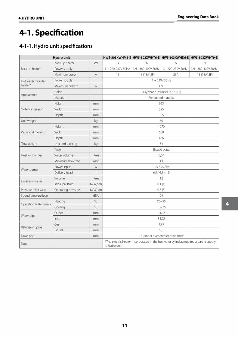
4-1. Specification4-1-1. Hydro unit specifications
Hydro unit HWS-803XWHM3-E HWS-803XWHT6-E HWS-803XWHD6-E HWS-803XWHT9-E
Back up heater
back up heater kW 3 6 6 9
Power supply 1 ~ 220-230V 50Hz 3N~ 380-400V 50Hz 3~ 220-230V 50Hz 3N~ 380-400V 50Hz
Maximum current A 13 13 (13A*2P) 23A 13 (13A*3P)
Hot water cylinder heater*
Power supply 1 ~ 230V 50Hz
Maximum current A 12.0
AppearanceColor Silky shade (Muncel 1Y8.5-0.5)
Material Pre-coated material
Outer dimension
Height mm 925
Width mm 525
Depth mm 355
Unit weight kg 50
Packing dimension
Height mm 1070
Width mm 608
Depth mm 436
Total weight Unit and packing kg 54
Heat exchanger
Type Brazed plate
Water volume litres 0,67
Minimum flow rate l/min 13
Water pumpPower input W 125 / 95 / 65
Delivery head m 6.5 / 6.1 / 4.5
Expansion vesselVolume litres 12
Initial pressure MPa(bar) 0.1 (1)
Pressure relief valve Operating pressure MPa(bar) 0.3 (3)
Sound pressure level dBA 29
Operation water temp.Heating °C 20~55
Cooling °C 10~25
Water pipeOutlet mm 34,92
Inlet mm 34,92
Refrigerant pipeGas mm 15,9
Liquid mm 9,5
Drain port mm 16.0 inner diameter for drain hose
Note * The electric heater, incorporated in the hot water cylinder, requires separete supply to hydro unit.
4.HYDRO UNIT Engineering Data Book
11
4
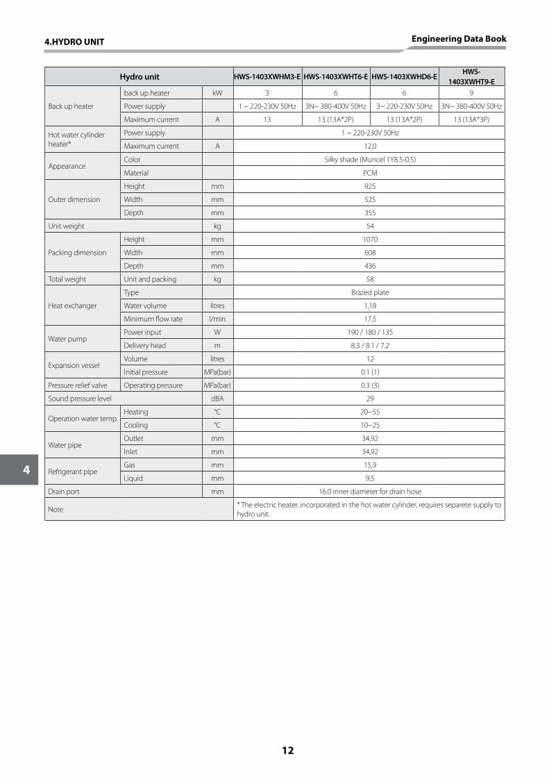
Hydro unit HWS-1403XWHM3-E HWS-1403XWHT6-E HWS-1403XWHD6-EHWS-
1403XWHT9-E
Back up heater
back up heater kW 3 6 6 9
Power supply 1 ~ 220-230V 50Hz 3N~ 380-400V 50Hz 3~ 220-230V 50Hz 3N~ 380-400V 50Hz
Maximum current A 13 13 (13A*2P) 13 (13A*2P) 13 (13A*3P)
Hot water cylinder heater*
Power supply 1 ~ 220-230V 50Hz
Maximum current A 12,0
AppearanceColor Silky shade (Muncel 1Y8.5-0.5)
Material PCM
Outer dimension
Height mm 925
Width mm 525
Depth mm 355
Unit weight kg 54
Packing dimension
Height mm 1070
Width mm 608
Depth mm 436
Total weight Unit and packing kg 58
Heat exchanger
Type Brazed plate
Water volume litres 1,18
Minimum flow rate l/min 17,5
Water pumpPower input W 190 / 180 / 135
Delivery head m 8.3 / 8.1 / 7.2
Expansion vesselVolume litres 12
Initial pressure MPa(bar) 0.1 (1)
Pressure relief valve Operating pressure MPa(bar) 0.3 (3)
Sound pressure level dBA 29
Operation water temp.Heating °C 20~55
Cooling °C 10~25
Water pipeOutlet mm 34,92
Inlet mm 34,92
Refrigerant pipeGas mm 15,9
Liquid mm 9,5
Drain port mm 16.0 inner diameter for drain hose
Note * The electric heater, incorporated in the hot water cylinder, requires separete supply to hydro unit.
12
4
4.HYDRO UNIT Engineering Data Book
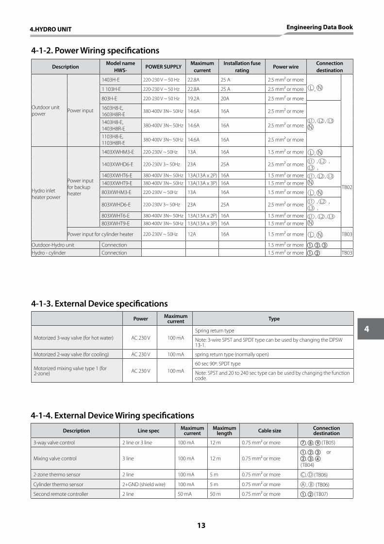
4-1-4. External Device Wiring specifications
Description Line spec Maximum current
Maximum length Cable size Connection
destination
3-way valve control 2 line or 3 line 100 mA 12 m 0.75 mm² or more , , (TB05)
Mixing valve control 3 line 100 mA 12 m 0.75 mm² or more, , , ,
(TB04)
or
2-zone thermo sensor 2 line 100 mA 5 m 0.75 mm² or more C , D (TB06)
Cylinder thermo sensor 2+GND (shield wire) 100 mA 5 m 0.75 mm² or more A , B (TB06)
Second remote controller 2 line 50 mA 50 m 0.75 mm² or more , (TB07)
4-1-3. External Device specifications
Power Maximum current Type
Motorized 3-way valve (for hot water) AC 230 V 100 mASpring return type
Note: 3-wire SPST and SPDT type can be used by changing the DPSW 13-1.
Motorized 2-way valve (for cooling) AC 230 V 100 mA spring return type (normally open)
Motorized mixing valve type 1 (for 2-zone) AC 230 V 100 mA
60 sec 90º. SPDT type
Note: SPST and 20 to 240 sec type can be used by changing the function code.
4-1-2. Power Wiring specifications
DescriptionModel name
HWS-POWER SUPPLY
Maximum current
Installation fuse rating
Power wireConnection destination
Outdoor unit power Power input
1403H-E 220-230 V ~ 50 Hz 22.8A 25 A 2.5 mm² or more
, 1 103H-E 220-230 V ~ 50 Hz 22.8A 25 A 2.5 mm² or more
803H-E 220-230 V ~ 50 Hz 19.2A 20A 2.5 mm² or more
1 , 2 , 3
1603H8-E, 1603H8R-E
380-400V 3N~ 50Hz 14.6A 16A 2.5 mm² or more
1403H8-E, 1403H8R-E
380-400V 3N~ 50Hz 14.6A 16A 2.5 mm² or more
1103H8-E, 1103H8R-E
380-400V 3N~ 50Hz 14.6A 16A 2.5 mm² or more
Hydro inlet heater power
Power input for backup heater
1403XWHM3-E 220-230V ~ 50Hz 13A 16A 1.5 mm² or more ,
TB02
1403XWHD6-E 220-230V 3~ 50Hz 23A 25A 2.5 mm² or more 1 , 2 , 3 ,
1403XWHT6-E 380-400V 3N~ 50Hz 13A(13A x 2P) 16A 1.5 mm² or more 1 , 2 , 3 1403XWHT9-E 380-400V 3N~ 50Hz 13A(13A x 3P) 16A 1.5 mm² or more
803XWHM3-E 220-230V ~ 50Hz 13A 16A 1.5 mm² or more ,
803XWHD6-E 220-230V 3~ 50Hz 23A 25A 2.5 mm² or more 1 , 2 , 3 ,
803XWHT6-E 380-400V 3N~ 50Hz 13A(13A x 2P) 16A 1.5 mm² or more 1 , 2 , 3 803XWHT9-E 380-400V 3N~ 50Hz 13A(13A x 3P) 16A 1.5 mm² or more
Power input for cylinder heater 220-230V ~ 50Hz 12A 16A 1.5 mm² or more , TB03
Outdoor-Hydro unit Connection 1.5 mm² or more , , Hydro - cylinder Connection 1.5 mm² or more , TB03
4.HYDRO UNIT Engineering Data Book
13
4
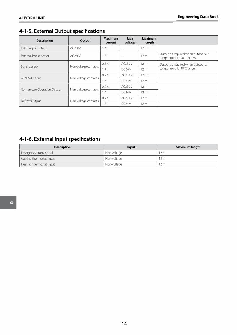
Description Input Maximum length
Emergency stop control Non-voltage 12 m
Cooling thermostat input Non-voltage 12 m
Heating thermostat input Non-voltage 12 m
4-1-6. External Input specifications
4-1-5. External Output specifications
Description Output Maximum current
Max voltage
Maximum length
External pump No.1 AC230V 1 A – 12 m
External boost heater AC230V 1 A – 12 m Output as required when outdoor air temperature is -20°C or less
Boiler control Non-voltage contacts0.5 A AC230 V 12 m Output as required when outdoor air
temperature is -10°C or less1 A DC24 V 12 m
ALARM Output Non-voltage contacts0.5 A AC230 V 12 m
1 A DC24 V 12 m
Compressor Operation Output Non-voltage contacts0.5 A AC230 V 12 m
1 A DC24 V 12 m
Defrost Output Non-voltage contacts0.5 A AC230 V 12 m
1 A DC24 V 12 m
14
4
4.HYDRO UNIT Engineering Data Book
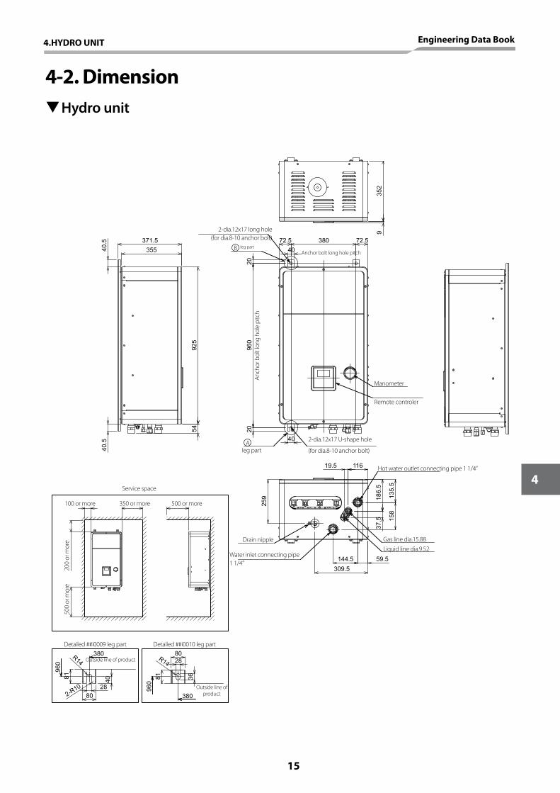
4-2. Dimension THydro unit
960
40
380
4020
2072.5 72.5
135.
515
8
186.
5
59.5144.5
11619.5
352
37.5
925
54
309.5
259
371.5
35540.5
40.5
9
81
R14
80
960
40
2-R10
380 80R14
36
960
28
380
28
81
2-dia.12x17 long hole (for dia.8-10 anchor bolt)
2-dia.12x17 U-shape hole
(for dia.8-10 anchor bolt)
Hot water outlet connecting pipe 1 1/4”
Water inlet connecting pipe 1 1/4”
Anchor bolt long hole pitchleg part
leg part
Manometer
Remote controler
Anch
or b
olt l
ong
hole
pitc
h
Gas line dia.15.88Drain nippleLiquid line dia.9.52
B
A
Service space
Detailed ##i0009 leg part Detailed ##i0010 leg part
100 or more 350 or more 500 or more
200
or m
ore
500
or m
ore
Outside line of product
Outside line of product
4.HYDRO UNIT Engineering Data Book
15
4
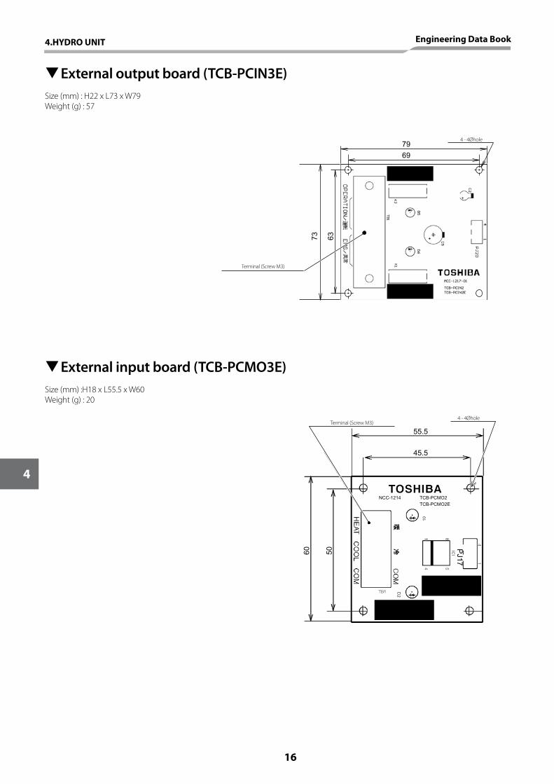
55.5
45.5
60 50
NCC-1214 TCB-PCMO2TCB-PCMO2E
PJ17
69
79
6373
TExternal output board (TCB-PCIN3E)Size (mm) : H22 x L73 x W79Weight (g) : 57
TExternal input board (TCB-PCMO3E)Size (mm) :H18 x L55.5 x W60Weight (g) : 20
4 - 4Øhole
4 - 4Øhole
Terminal (Screw M3)
Terminal (Screw M3)
16
4
4.HYDRO UNIT Engineering Data Book
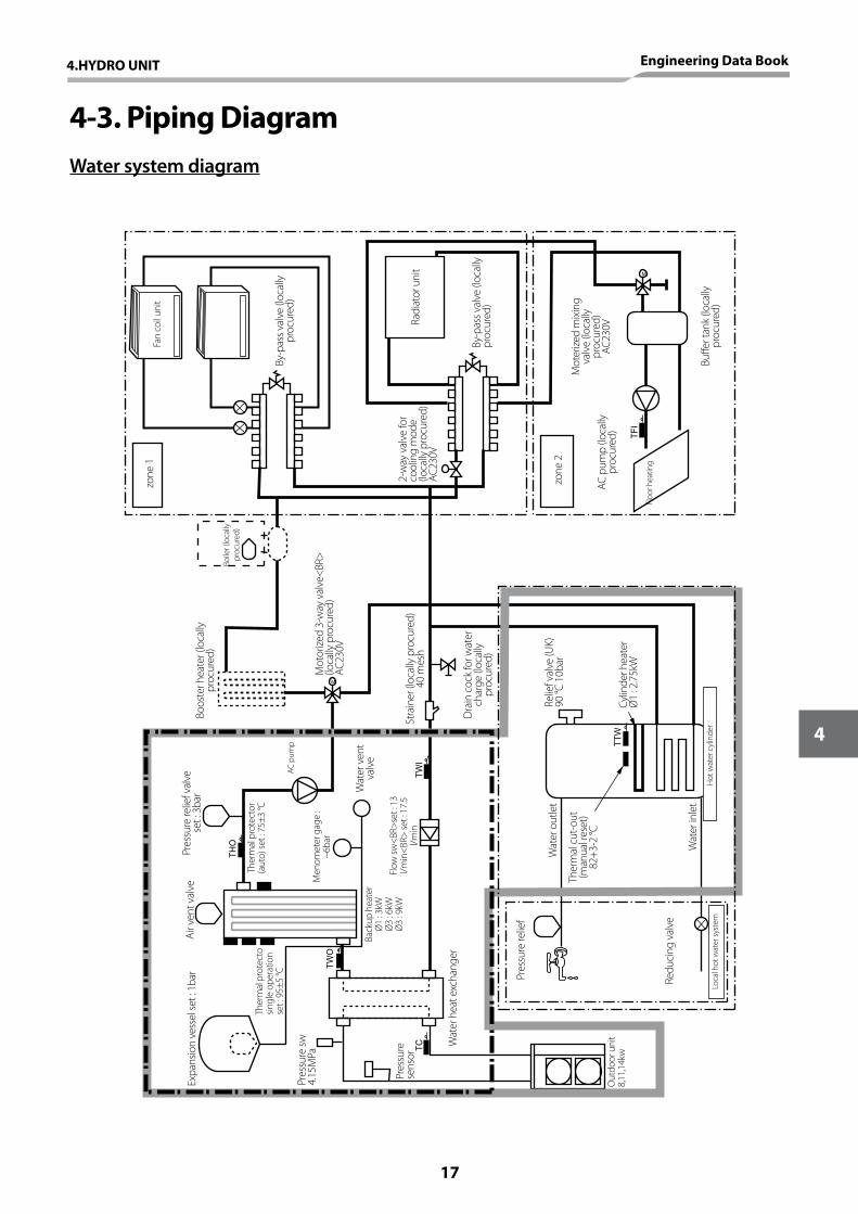
4-3. Piping DiagramWater system diagram
M
M
TF
I
TT
W
TC
TW
O
TH
O
TW
I
Expa
nsio
n ve
ssel
set :
1ba
r
Ther
mal
pro
tect
o sin
gle
oper
atio
n se
t : 9
5±5
°C
Air v
ent v
alve
Pres
sure
sw
4.15
MPa
Pres
sure
se
nsor
Back
up h
eate
rØ
1 : 3
kWØ
3 : 6
kWØ
3 : 9
kWFl
ow sw
<BR>
set :
13
l/min
<BR>
set :
17.
5 l/m
in
Men
omet
er g
age
: ~6
bar
Ther
mal
pro
tect
or
(aut
o) se
t : 7
5±3
°C
Pres
sure
relie
f val
ve
set :
3ba
r
AC p
ump
Wat
er v
ent
valv
e
Boos
ter h
eate
r (lo
cally
pr
ocur
ed)
Boile
r (lo
cally
pr
ocur
ed)
zone
1
zone
2
Mot
orize
d 3-
way
val
ve<B
R>
(loca
lly p
rocu
red)
AC23
0V
Stra
iner
(loc
ally
pro
cure
d)
40 m
esh
Dra
in c
ock
for w
ater
ch
arge
(loc
ally
pr
ocur
ed)
Relie
f val
ve (U
K)90
°C 1
0bar
Cylin
der h
eate
rØ
1 : 2
.75k
W
Hot
wat
er c
ylin
der
Wat
er in
let
Ther
mal
cut
-out
(m
anua
l res
et)
82+3
-2 °C
Wat
er o
utle
t
Pres
sure
relie
f
Redu
cing
val
ve
Loca
l hot
wat
er sy
stem
Out
door
uni
t8,
11,1
4kw
Wat
er h
eat e
xcha
nger
Fan
coil u
nit
By-p
ass v
alve
(loc
ally
pr
ocur
ed)
Radi
ator
uni
t2-
way
val
ve fo
r co
olin
g m
ode
(loca
lly p
rocu
red)
AC23
0V
By-p
ass v
alve
(loc
ally
pr
ocur
ed)
AC p
ump
(loca
lly
proc
ured
)
Floo
r hea
ting
Mot
erize
d m
ixin
g va
lve
(loca
lly
proc
ured
)AC
230V
Buffe
r tan
k (lo
cally
pr
ocur
ed)
4.HYDRO UNIT Engineering Data Book
17
4
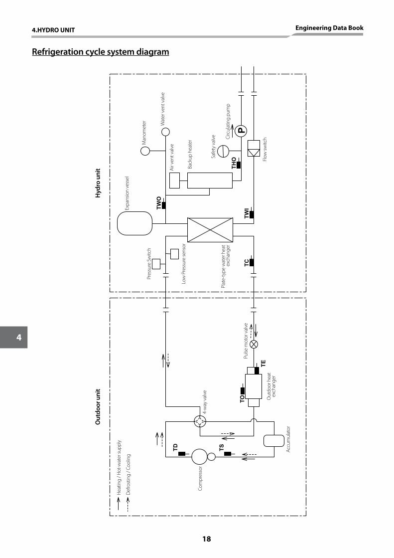
Refrigeration cycle system diagram
P
TWO
THO
TWI
TC
TE
TO
TS
TD
Hea
ting
/ Hot
-wat
er su
pply
Def
rost
ing
/ Coo
ling
Com
pres
sor
Accu
mul
ator
Out
door
hea
t ex
chan
ger
Pulse
mot
or v
alve
Plat
e-ty
pe w
ater
hea
t ex
chan
ger
Low
Pre
ssur
e se
nsor
Pres
sure
Sw
itch
Expa
nsio
n ve
ssel
Out
door
uni
tH
ydro
uni
t
Man
omet
er Wat
er v
ent v
alve
Air v
ent v
alve
Back
up h
eate
r
Safe
ty v
alve Ci
rcul
atin
g pu
mp
Flow
switc
h
4-w
ay v
alve
18
4
4.HYDRO UNIT Engineering Data Book
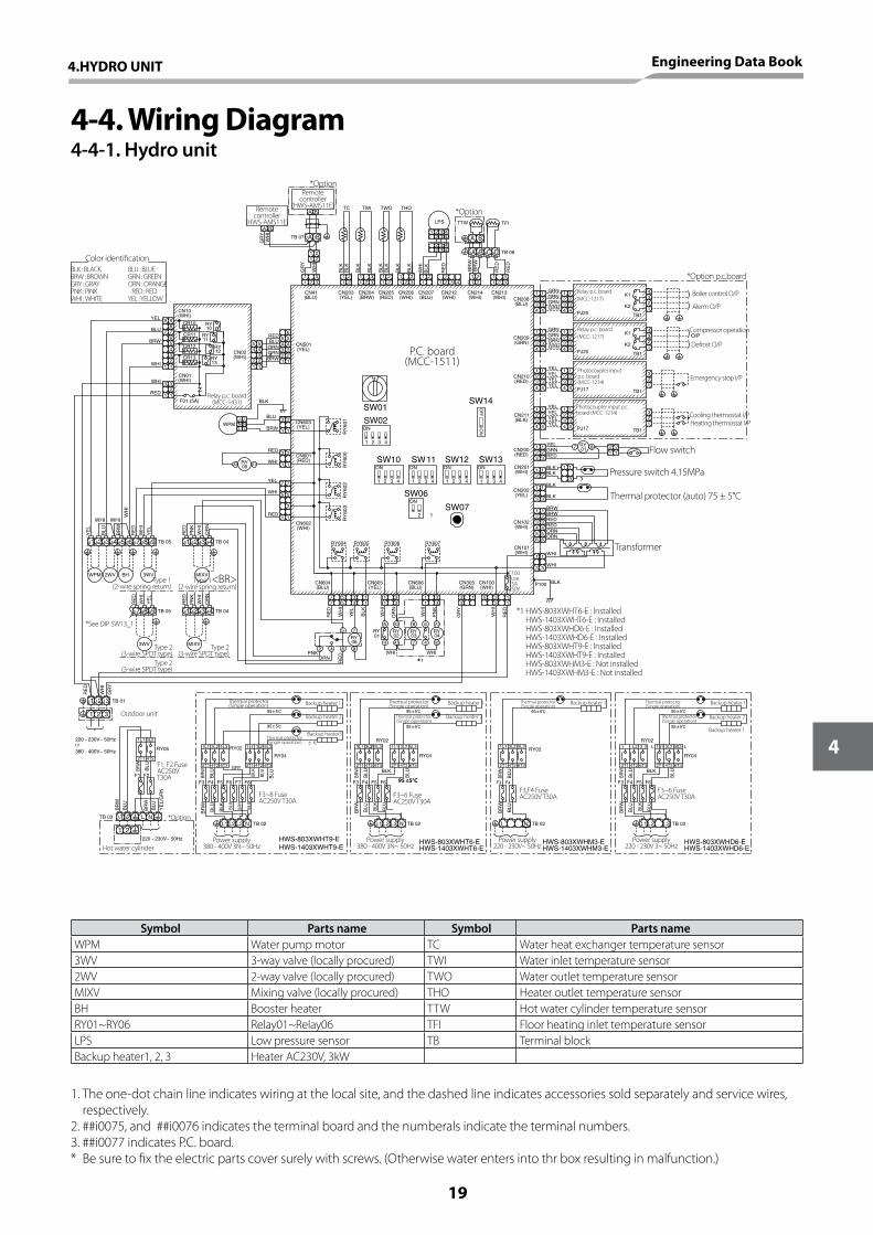
4-4. Wiring Diagram4-4-1. Hydro unit
A B
GR
YW
HI
A B
TB 07
GR
Y
WH
I
BLK
BLK
BLK
BLK
BLK
BLK
BLK
BLK
1 32 1 3 42 221
113
211 2
2 311 3
1 21 2
1 21 2
11
2 33 2
1 321 3
1 21 2
THOTWOTWITC
LPS
RE
D
RE
D
BR
WB
RW
RE
D
WH
IB
LK
TFITTW
TB 06
CN208(BLU)
CN213(WHI)
CN214(WHI)
CN206(WHI)
CN205(RED)
CN204(BRW)
CN203(YEL)
CN41(BLU)
CN501(YEL)
CN207(BLU)
CN212(WHI)
CN102(WHI)
CN101(WHI)
CN202(YEL)
CN201(WHI)
CN200(RED)
CN211(BLK)
CN210(RED)
CN209(GRN)
RY607RY606RY605RY604
RY
601
RY
600
RY
603
RY
602
CN601(RED)
CN603(YEL)
CN602(WHI)
WHI
YEL
WHI
RED
RED
BRW
BLU
WPM
BLK
RY05 A1A2
LN N
L
SW10 SW11 SW12 SW13
SW06
SW07
SW14SW01
SW02
1 2 43
ON
ON
1 2 3 4 1 2 3 4 1 2 3 41 2 3 4
ON ON
2 1
ON
ON
OFF
ON
3
5
7
1
3
1
3
1
3
1
3
1
5
7
1
TB 04
MIXV
TB 04TB 05
RE
D
RE
D
OR
N
PN
K
WH
I
WH
I
YE
L
RE
D
OR
N
WH
I
PN
K
WHI WHI
YE
L
BLU
BR
W
WH
IR
ED
WH
I
YE
L
BH 3WV2WVWPM
TB 055251 53 54 5655 57 5958 4241 43 44
44434241
MIXV
595857
3WV
RE
DPNKORN
4 6 82
75RY06
A1
A2
6
4
8
7
A2
A14
6RY01
WHI WHI
RY02
RY04
RY03
*1
RE
D
WH
I
GR
Y
RE
D
WH
I
BLK
YE
L
WH
I
OR
N
WH
I
PN
K
CN604(BLU)
CN605(YEL)
CN606(BLU)
CN305(GRN)
CN100(WHI)
3 13 17
7 55
311 3
1 31 3
133 3
3115
WHI
WHI
P100 BLK
ORNORNREDREDBRWBRW
BLKBLK
RED
YELGRN
BLK
BLK
1 1
123456
1
1 1
1 1
456
23
1234
1
4
23
1234
1
4
23
1234
1
4
23
1234
1
4
23
1234
1
4
23
1234
1
4
23
1234
1
4
23
1234
1
4
23
3 3
323
1 1
1 1
3 32 2
23 3
12
2 21
3
12
3
12
43
12
43
12
GRN
GRNGRN
GRN
GRN
GRNGRNGRN
YEL
YELYELYEL
YEL
YELYELYEL
O/P
7 8RY01
PJ20 TB1
K1
K2
K1
K2PJ20 TB1
PJ17 TB1
PJ17 TB1
WH
I
RE
D
GR
Y
TB 013
31 2
12111
34
2
65
1
5432
22 1
5 5
1 1
43 3
4
REDBLU
GRNORN
BRWCN02(WHI)
F01 (5A)
CN01(WHI)
3
1 123
21 1
345 56
9
78
7
9
RED
WHI
WHI
BLU
BRW
YEL
CN10(WHI)
RY10
CR10
CR11
CR12
CR13
RY11
RY12
RY13
1
6D6C6B6A
A B7B7A2 432 3 4
2 432
13 4
220 - 230V~ 50Hz
380 - 400V~ 50Hz
3 31 2 NL
1 2
TB 03
220 - 230V~ 50Hz
BR
W
BLU
BR
W
BLU
BR
W
BLU
YE
L/G
RN
F1 F2
RY05
2T1
1L1
4T2
3L2
95 5
95 5
2T1
1L1 1L1
4T2
3L2
6T3
5L3 3L2 5L3
6T32T1 4T2
1 L1 2L 3 5L3RY02
F3 F4 F6F5 F8F7
BLU
GR
Y
GRY
BLU
BLU
BLU
BR
W
BLU
BRW
BLU
BLK
BLK
TB 02L1 L2 L3 N
HWS-803XWHT9-EHWS-1403XWHT9-E
RY04
95 5
95 5
BR
W
BLU
BRW
BLU
BLU
BLK
BLK
BLU
RY02
6T3
5L3
3T61T2 2T4
1 2 1L1 3L2
2T1 4T2
RY04
F3 F6F5F4
TB 021L 2L L3 N
HWS-803XWHT6-EHWS-1403XWHT6-E
95 5
95 5
BR
W
BLU
BRW
BLU
BLU
BLK
BLK
BLU
RY02
6T3
5L3
3T61T2 2T4
3 L 5 1 L1 2L 3 1L1 3L2
2T1 4T2
RY04
F3 F6F5F4
TB 021L 2L L3
HWS-803XWHD6-EHWS-1403XWHD6-E
95 5
RY02
6T32T1 4T2
5L31L1 3L2
F4F3
BR
W
BLU
BRW
BLU
L N TB 02
HWS-803XWHM3-EHWS-1403XWHM3-E
*Option
Remote controller
(HWS-AMS11E)
Remote controller
(HWS-AMS11E)*Option
P.C. board(MCC-1511)
Relay p.c. board(MCC-1431)
Type 1(2-wire spring return)
Type 1<BR> (2-wire spring return)
Type 2(3-wire SPDT type)
Type 2(3-wire SPDT type)
Type 2(3-wire SPDT type)
Hot water cylinder
Outdoor unit
F1, F2 Fuse AC250V T30A
Power supply380 - 400V 3N~ 50Hz
Power supply380 - 400V 3N~ 50Hz
Power supply220 - 230V~ 50Hz
Power supply220 - 230V 3~ 50Hz
Thermal protector(Single operation)
95 ±5°C
Backup heater 1 Backup heater 1Backup heater 1Backup heater 1
Backup heater 2Backup heater 2Backup heater 2
Backup heater3
F3~6 Fuse AC250V T30A
F3,F4 Fuse AC250V T30AF3~6 Fuse
AC250V T30AF3~8 Fuse AC250V T30A
Thermal protector (Single operation)
Thermal protector (Single operation)
Thermal protector (Single operation)
Thermal protector(Single operation)
Thermal protector (Single operation)
Thermal protector (Single operation)
Backup heater 1
*1 HWS-803XWHT6-E : Installed HWS-1403XWHT6-E : Installed HWS-803XWHD6-E : Installed HWS-1403XWHD6-E : Installed HWS-803XWHT9-E : Installed HWS-1403XWHT9-E : Installed HWS-803XWHM3-E : Not installed HWS-1403XWHM3-E : Not installed
Transformer
Thermal protector (auto) 75 ± 5°C
Pressure switch 4.15MPa
Flow switch
Cooling thermostat I/P
Compressor operation
Boiler control O/P
Emergency stop I/P
Heating thermostat I/P
Defrost O/P
Alerm O/P
F100FuseT5A250V
*See DIP SW13_1
Photocoupler input p.c. board (MCC-1214)
Photocoupler input p.c. board(MCC-1214)
Relay p.c. board (MCC-1217)
Relay p.c. board (MCC-1217)
BLK : BLACKBRW : BROWNGRY : GRAYPNK : PINKWHI : WHITE
BLU : BLUEGRN : GREENORN : ORANGEXRED : REDYEL : YELLOW
*Option p.c.board
Color identification
Symbol Parts name Symbol Parts nameWPM Water pump motor TC Water heat exchanger temperature sensor3WV 3-way valve (locally procured) TWI Water inlet temperature sensor2WV 2-way valve (locally procured) TWO Water outlet temperature sensorMIXV Mixing valve (locally procured) THO Heater outlet temperature sensorBH Booster heater TTW Hot water cylinder temperature sensorRY01~RY06 Relay01~Relay06 TFI Floor heating inlet temperature sensorLPS Low pressure sensor TB Terminal blockBackup heater1, 2, 3 Heater AC230V, 3kW
1. The one-dot chain line indicates wiring at the local site, and the dashed line indicates accessories sold separately and service wires, respectively.
2. ##i0075, and ##i0076 indicates the terminal board and the numberals indicate the terminal numbers.3. ##i0077 indicates P.C. board.* Be sure to fix the electric parts cover surely with screws. (Otherwise water enters into thr box resulting in malfunction.)
*Option
or
4.HYDRO UNIT Engineering Data Book
19
4
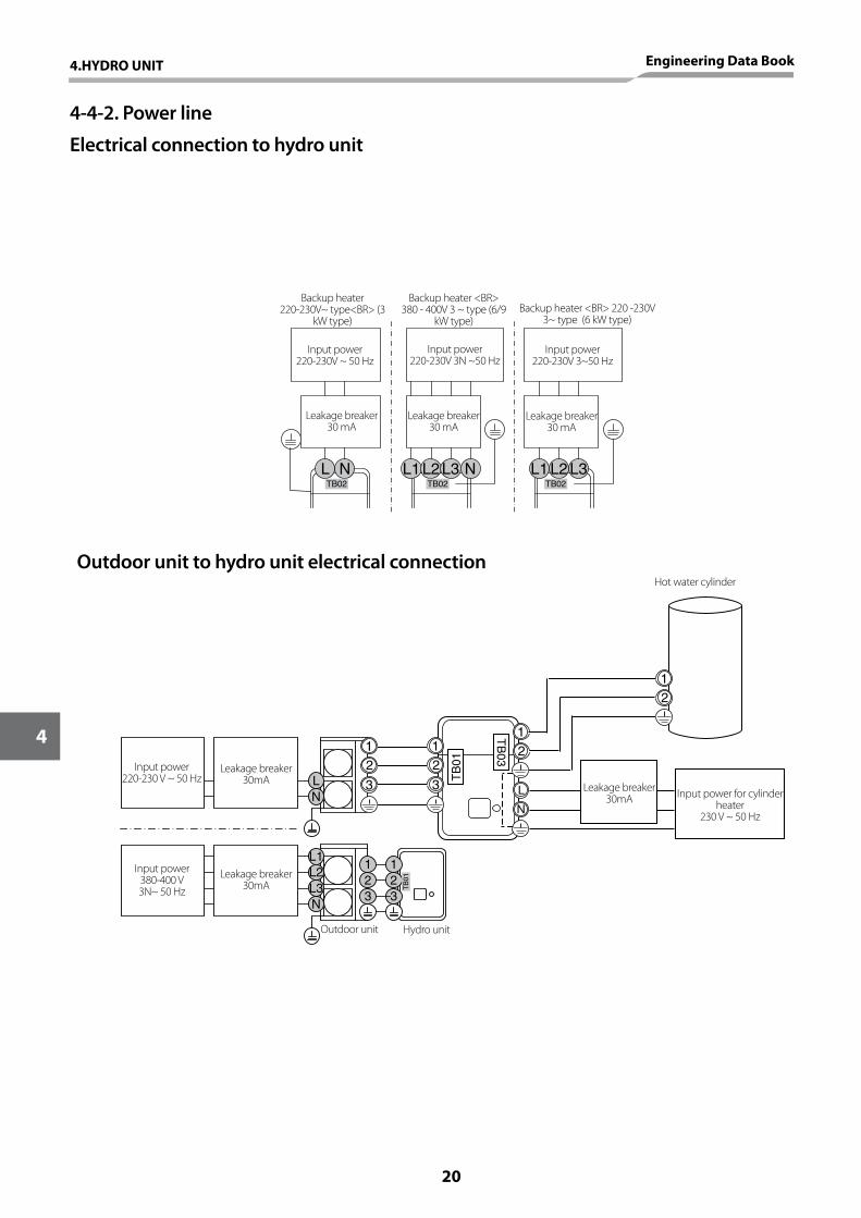
4-4-2. Power line
Electrical connection to hydro unit
L N L1 L2 L3 N L1 L2 L302BTTB02TB02
NL
N
1
32
1
32
L1L2L3 T
B01
12
3
12
3
12
12
L
N
TB
03
TB
01
Backup heater 220-230V~ type<BR> (3
kW type)
Backup heater <BR> 380 - 400V 3 ~ type (6/9
kW type)Backup heater <BR> 220 -230V
3~ type (6 kW type)
Input power220-230V ~ 50 Hz
Input power 220-230V 3N ~50 Hz
Input power 220-230V 3~50 Hz
Leakage breaker30 mA
Leakage breaker 30 mA
Leakage breaker 30 mA
Hot water cylinder
Leakage breaker 30mA
Leakage breaker 30mA
Leakage breaker 30mA
Input power for cylinder heater
230 V ~ 50 Hz
Outdoor unit Hydro unit
Input power220-230 V ~ 50 Hz
Input power380-400 V 3N~ 50 Hz
Outdoor unit to hydro unit electrical connection
20
4
4.HYDRO UNIT Engineering Data Book
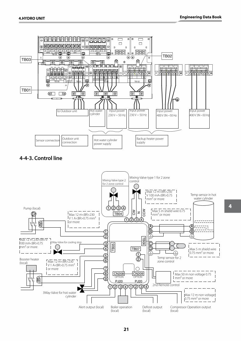
TB07
AB
CD
12
34
56
AB
1 2 3 4
1 2 3 4 1 2 3 4
TB
05
PJ20PJ20
TB
06
CN208 CN209
12
789
1 2 3 4
TB04 CW
CC
WN
6B6A 6D6CTF1
TB 06
11 12 13
TB 01
Don't apply 220-240Vorbreakdownwill occur.
TTW31 32 L
TB 03HOT WATER CYLINDER
L
TB 02
N
1 32 L2L1 L3 N
WPM51
TB 05
52 41MIXV
53 54 55 56 57 58 592WV BH 3WV
42 43 44
TB 04
N
L3L1 L2 N L1 L2 L3
TB03
TB01
TB02
to Outdoor unit
Sensor connection Outdoor unit connection
Hot water cylinder power supply
Backup heater power supply
Hot water cylinder
Input power230 V ~ 50 Hz
Input power 230 V ~ 50 Hz
Input power400 V 3N ~50 Hz
Input power400 V 3N ~50 Hz
4-4-3. Control line
Max 12 m 230<BR>V 100 mA<BR>0.75 mm² or more
Max 12 m<BR>230 V 1 A<BR>0.75 mm² or more
Max 12 m<BR>230 V 100 mA<BR>0.75 mm² or more
Max 5 m shield wire 0.75 mm² or more
Temp sensor for 2 zone control
2nd Remote control
Mixing-Valve type 1 for 2 zone controlMixing-Valve type 2
for 2 zone control
Pump (local)
Booster heater (local) Max 12 m<BR>230
V 1 A<BR>0.75 mm² or more
3Way-Valve for hot water cylinder
Alert output (local) Boiler operation (local)
Defrost output (local)
Compressor Operation output (local)
Max 12 m non voltage 0.75 mm² or more
Max 50 m non voltage 0.75 mm² or more
Max 5 m shield wire 0.75 mm² or more
2Way-Valve for cooling stop
Temp sensor in hot water cylinder
OPTION OPTION
4.HYDRO UNIT Engineering Data Book
21
4
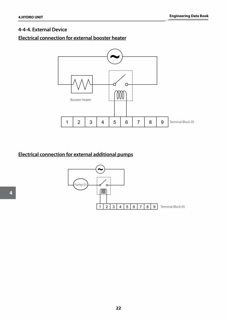
4-4-4. External Device
Electrical connection for external booster heater
1 2 3 4 5 6 7 8 9 Terminal Block 05
Booster Heater
Electrical connection for external additional pumps
1 2 3 4 5 6 7 8 9 Terminal Block 05
Pump 01
22
4
4.HYDRO UNIT Engineering Data Book
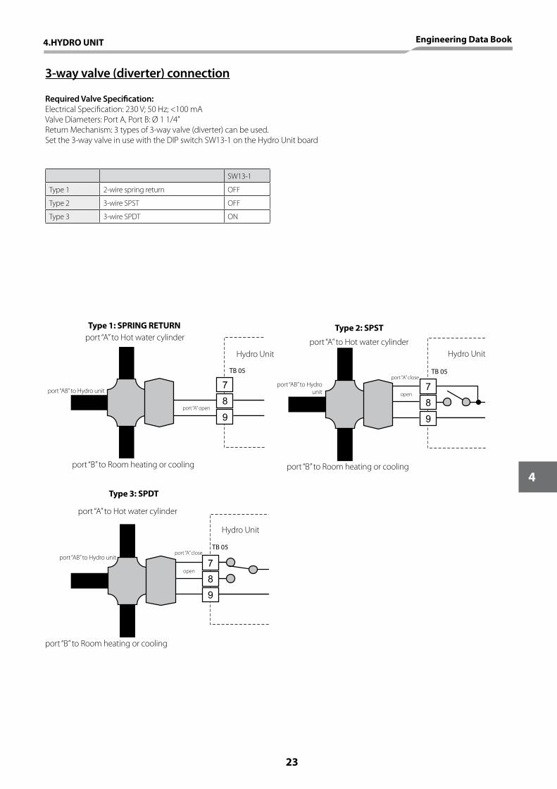
3-way valve (diverter) connection
Required Valve Specification:Electrical Specification: 230 V; 50 Hz; <100 mAValve Diameters: Port A, Port B: Ø 1 1/4”Return Mechanism: 3 types of 3-way valve (diverter) can be used.Set the 3-way valve in use with the DIP switch SW13-1 on the Hydro Unit board
SW13-1
Type 1 2-wire spring return OFF
Type 2 3-wire SPST OFF
Type 3 3-wire SPDT ON
7
8
9
7
8
9
7
8
9
TB 05 TB 05
TB 05
Type 1: SPRING RETURNport “A” to Hot water cylinder
Hydro Unit
Hydro Unit
port “A” open
port “AB” to Hydro unit
port “B” to Room heating or cooling
Type 2: SPST
port “A” to Hot water cylinder
port “A” closeport “AB” to Hydro
unit
port “B” to Room heating or cooling
open
Hydro Unit
Type 3: SPDT
port “A” to Hot water cylinder
port “AB” to Hydro unitport “A” close
port “B” to Room heating or cooling
open
4.HYDRO UNIT Engineering Data Book
23
4
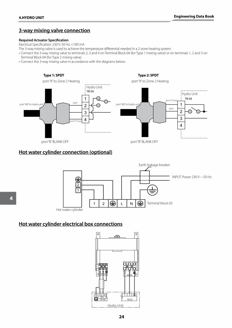
3-way mixing valve connection
Hot water cylinder connection (optional)
Hot water cylinder electrical box connections
Required Actuator SpecificationElectrical Specification: 230 V; 50 Hz; <100 mAThe 3-way mixing valve is used to achieve the temperature differential needed in a 2-zone heating system.•Connectthe3-waymixingvalvetoterminals2,3and4onTerminalBlock04(forType1mixingvalve)oronterminals1,2and3on
Terminal Block 04 (for Type 2 mixing valve).•Connectthe3-waymixingvalveinaccordancewiththediagramsbelow:
2
1
3
4
2
1
3
4
TB 04
TB 04
Hydro Unit
Hydro Unit
Type 1: SPDT Type 2: SPDT
port “A” to Zone 2 Heating port “A” to Zone 2 Heating
port “AB” to Hydro unit port “AB” to Hydro unit
port “A” close
port “A” close
port “B” BLANK OFF port “B” BLANK OFF
open
open
1 2 L N
1
2
Earth leakage breaker
INPUT Power 230 V ~ 50 Hz
Terminal block 03
Hot water cylinder
Hydro Unit
24
4
4.HYDRO UNIT Engineering Data Book
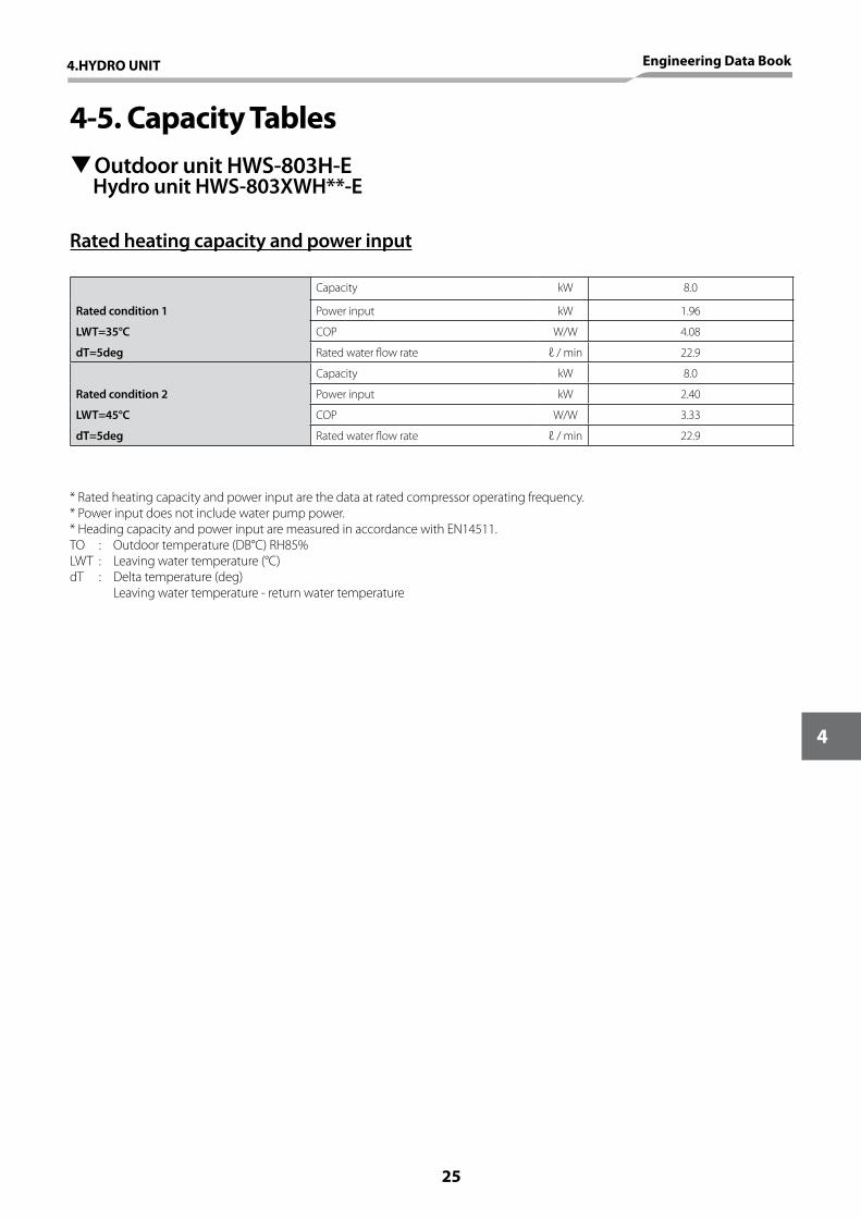
4-5. Capacity Tables TOutdoor unit HWS-803H-E
Hydro unit HWS-803XWH**-E
Rated heating capacity and power input
Rated condition 1
Capacity kW 8.0
Power input kW 1.96
LWT=35°C COP W/W 4.08
dT=5deg Rated water flow rate ℓ / min 22.9
Rated condition 2
Capacity kW 8.0
Power input kW 2.40
LWT=45°C COP W/W 3.33
dT=5deg Rated water flow rate ℓ / min 22.9
* Rated heating capacity and power input are the data at rated compressor operating frequency.* Power input does not include water pump power.* Heading capacity and power input are measured in accordance with EN14511.TO : Outdoor temperature (DB°C) RH85%LWT : Leaving water temperature (°C)dT : Delta temperature (deg) Leaving water temperature - return water temperature
4.HYDRO UNIT Engineering Data Book
25
4
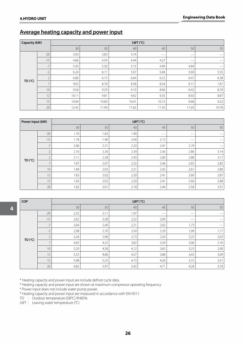
Average heating capacity and power input
Capacity (kW) LWT (°C)
30 35 40 45 50 55
TO (°C)
-20 3.93 3.83 3.74 — — —
-15 4.66 4.54 4.44 4.27 — —
-7 5.45 5.30 5.15 4.99 4.84 —
-2 6.24 6.11 5.97 5.84 5.69 5.55
2 6.86 6.75 6.64 6.52 6.47 6.38
7 9.02 8.78 8.58 8.34 8.11 7.87
10 9.56 9.29 9.10 8.84 8.42 8.29
12 10.11 9.81 9.62 9.35 8.92 8.87
15 10.94 10.60 10.41 10.13 9.68 9.52
20 12.42 11.99 11.82 11.50 11.03 10.78
Power input (kW) LWT (°C)
30 35 40 45 50 55
TO (°C)
-20 1.70 1.82 1.90 — — —
-15 1.78 1.90 2.00 2.13 — —
-7 2.06 2.21 2.33 2.47 2.79 —
-2 2.10 2.26 2.39 2.56 2.86 3.14
2 2.11 2.28 2.43 2.60 2.88 3.17
7 1.87 2.07 2.25 2.46 2.65 2.85
10 1.84 2.03 2.21 2.42 2.61 2.86
12 1.83 2.02 2.20 2.41 2.60 2.87
15 1.83 2.02 2.20 2.41 2.60 2.88
20 1.82 2.01 2.18 2.44 2.58 2.91
COP LWT (°C)
30 35 40 45 50 55
TO (°C)
-20 2,32 2,11 1,97 — — —
-15 2,62 2,38 2,22 2,00 — —
-7 2,64 2,40 2,21 2,02 1,73 —
-2 2,98 2,70 2,50 2,29 1,99 1,77
2 3,26 2,96 2,73 2,50 2,25 2,02
7 4,82 4,25 3,82 3,39 3,06 2,76
10 5,20 4,58 4,12 3,65 3,23 2,90
12 5,52 4,86 4,37 3,88 3,43 3,09
15 5,98 5,25 4,73 4,20 3,72 3,31
20 6,82 5,97 5,42 4,71 4,28 3,70
* Heating capacity and power input are include defrost cycle data.* Heating capacity and power input are shown at maximum compressor operating frequency* Power input does not include water pump power.* Heating capacity and power input are measured in accordance with EN14511.TO : Outdoor temperature (DB°C) RH85%LWT : Leaving water temperature (°C)
26
4
4.HYDRO UNIT Engineering Data Book
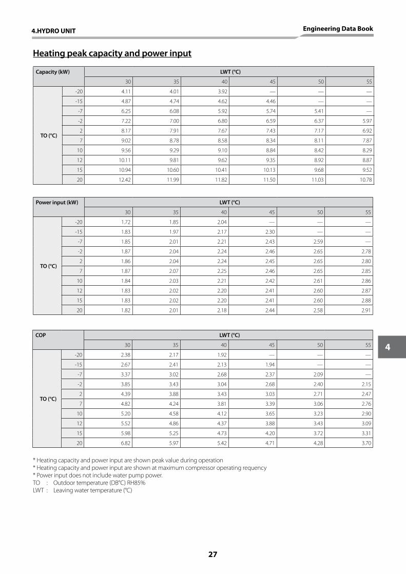
Heating peak capacity and power input
Capacity (kW) LWT (°C)
30 35 40 45 50 55
TO (°C)
-20 4.11 4.01 3.92 — — —
-15 4.87 4.74 4.62 4.46 — —
-7 6.25 6.08 5.92 5.74 5.41 —
-2 7.22 7.00 6.80 6.59 6.37 5.97
2 8.17 7.91 7.67 7.43 7.17 6.92
7 9.02 8.78 8.58 8.34 8.11 7.87
10 9.56 9.29 9.10 8.84 8.42 8.29
12 10.11 9.81 9.62 9.35 8.92 8.87
15 10.94 10.60 10.41 10.13 9.68 9.52
20 12.42 11.99 11.82 11.50 11.03 10.78
Power input (kW) LWT (°C)
30 35 40 45 50 55
TO (°C)
-20 1.72 1.85 2.04 — — —
-15 1.83 1.97 2.17 2.30 — —
-7 1.85 2.01 2.21 2.43 2.59 —
-2 1.87 2.04 2.24 2.46 2.65 2.78
2 1.86 2.04 2.24 2.45 2.65 2.80
7 1.87 2.07 2.25 2.46 2.65 2.85
10 1.84 2.03 2.21 2.42 2.61 2.86
12 1.83 2.02 2.20 2.41 2.60 2.87
15 1.83 2.02 2.20 2.41 2.60 2.88
20 1.82 2.01 2.18 2.44 2.58 2.91
COP LWT (°C)
30 35 40 45 50 55
TO (°C)
-20 2.38 2.17 1.92 — — —
-15 2.67 2.41 2.13 1.94 — —
-7 3.37 3.02 2.68 2.37 2.09 —
-2 3.85 3.43 3.04 2.68 2.40 2.15
2 4.39 3.88 3.43 3.03 2.71 2.47
7 4.82 4.24 3.81 3.39 3.06 2.76
10 5.20 4.58 4.12 3.65 3.23 2.90
12 5.52 4.86 4.37 3.88 3.43 3.09
15 5.98 5.25 4.73 4.20 3.72 3.31
20 6.82 5.97 5.42 4.71 4.28 3.70
* Heating capacity and power input are shown peak value during operation* Heating capacity and power input are shown at maximum compressor operating requency* Power input does not include water pump power.TO : Outdoor temperature (DB°C) RH85%LWT : Leaving water temperature (°C)
4.HYDRO UNIT Engineering Data Book
27
4
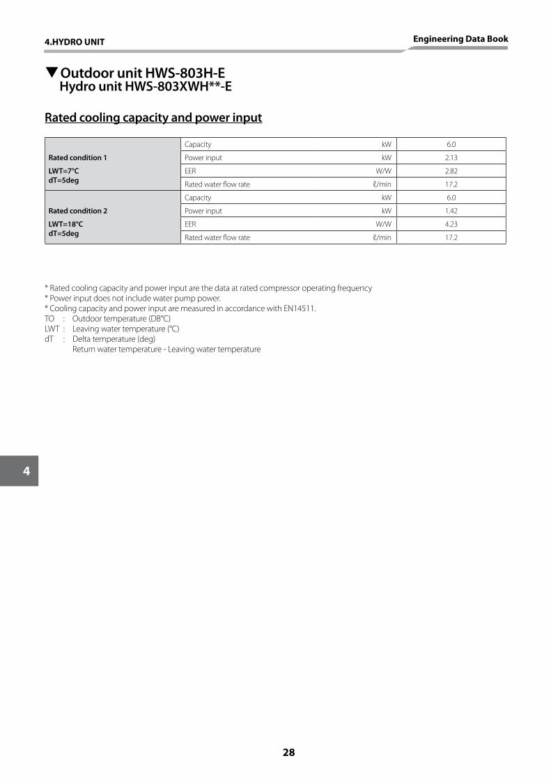
TOutdoor unit HWS-803H-E Hydro unit HWS-803XWH**-E
Rated cooling capacity and power input
Rated condition 1
Capacity kW 6.0
Power input kW 2.13
LWT=7°CdT=5deg
EER W/W 2.82
Rated water flow rate ℓ/min 17.2
Rated condition 2
Capacity kW 6.0
Power input kW 1.42
LWT=18°CdT=5deg
EER W/W 4.23
Rated water flow rate ℓ/min 17.2
* Rated cooling capacity and power input are the data at rated compressor operating frequency* Power input does not include water pump power.* Cooling capacity and power input are measured in accordance with EN14511.TO : Outdoor temperature (DB°C) LWT : Leaving water temperature (°C)dT : Delta temperature (deg) Return water temperature - Leaving water temperature
28
4
4.HYDRO UNIT Engineering Data Book
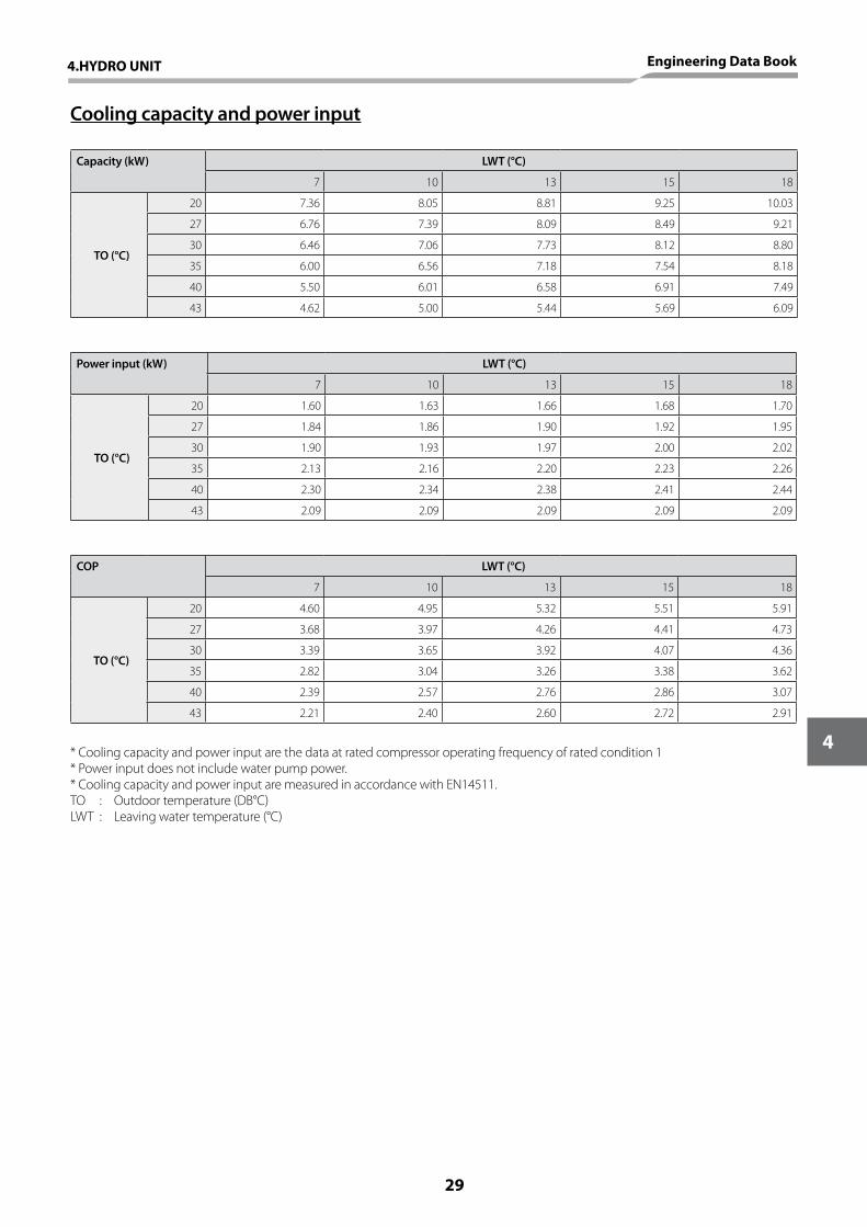
Cooling capacity and power input
Capacity (kW) LWT (°C)
7 10 13 15 18
TO (°C)
20 7.36 8.05 8.81 9.25 10.03
27 6.76 7.39 8.09 8.49 9.21
30 6.46 7.06 7.73 8.12 8.80
35 6.00 6.56 7.18 7.54 8.18
40 5.50 6.01 6.58 6.91 7.49
43 4.62 5.00 5.44 5.69 6.09
Power input (kW) LWT (°C)
7 10 13 15 18
TO (°C)
20 1.60 1.63 1.66 1.68 1.70
27 1.84 1.86 1.90 1.92 1.95
30 1.90 1.93 1.97 2.00 2.02
35 2.13 2.16 2.20 2.23 2.26
40 2.30 2.34 2.38 2.41 2.44
43 2.09 2.09 2.09 2.09 2.09
COP LWT (°C)
7 10 13 15 18
TO (°C)
20 4.60 4.95 5.32 5.51 5.91
27 3.68 3.97 4.26 4.41 4.73
30 3.39 3.65 3.92 4.07 4.36
35 2.82 3.04 3.26 3.38 3.62
40 2.39 2.57 2.76 2.86 3.07
43 2.21 2.40 2.60 2.72 2.91
* Cooling capacity and power input are the data at rated compressor operating frequency of rated condition 1* Power input does not include water pump power.* Cooling capacity and power input are measured in accordance with EN14511.TO : Outdoor temperature (DB°C) LWT : Leaving water temperature (°C)
4.HYDRO UNIT Engineering Data Book
29
4
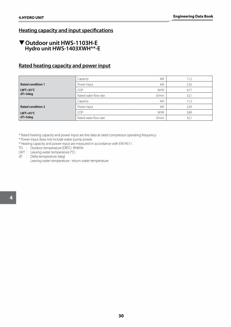
TOutdoor unit HWS-1103H-E Hydro unit HWS-1403XWH**-E
Rated heating capacity and power input
Heating capacity and input specifications
Rated condition 1
Capacity kW 11,2
Power input kW 2,35
LWT=35°CdT=5deg
COP W/W 4,77
Rated water flow rate ℓ/min 32,1
Rated condition 2
Capacity kW 11,2
Power input kW 2,95
LWT=45°CdT=5deg
COP W/W 3,80
Rated water flow rate ℓ/min 32,1
* Rated heating capacity and power input are the data at rated compressor operating frequency* Power input does not include water pump power.* Heating capacity and power input are measured in accordance with EN14511.TO : Outdoor temperature (DB°C) RH85%LWT : Leaving water temperature (°C)dT : Delta temperature (deg) Leaving water temperature - return water temperature
30
4
4.HYDRO UNIT Engineering Data Book
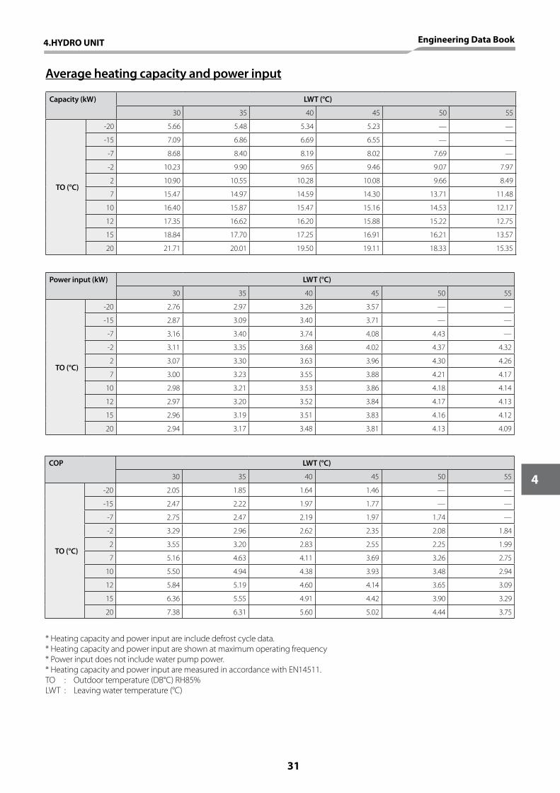
Average heating capacity and power input
Capacity (kW) LWT (°C)
30 35 40 45 50 55
TO (°C)
-20 5.66 5.48 5.34 5.23 — —
-15 7.09 6.86 6.69 6.55 — —
-7 8.68 8.40 8.19 8.02 7.69 —
-2 10.23 9.90 9.65 9.46 9.07 7.97
2 10.90 10.55 10.28 10.08 9.66 8.49
7 15.47 14.97 14.59 14.30 13.71 11.48
10 16.40 15.87 15.47 15.16 14.53 12.17
12 17.35 16.62 16.20 15.88 15.22 12.75
15 18.84 17.70 17.25 16.91 16.21 13.57
20 21.71 20.01 19.50 19.11 18.33 15.35
Power input (kW) LWT (°C)
30 35 40 45 50 55
TO (°C)
-20 2.76 2.97 3.26 3.57 — —
-15 2.87 3.09 3.40 3.71 — —
-7 3.16 3.40 3.74 4.08 4.43 —
-2 3.11 3.35 3.68 4.02 4.37 4.32
2 3.07 3.30 3.63 3.96 4.30 4.26
7 3.00 3.23 3.55 3.88 4.21 4.17
10 2.98 3.21 3.53 3.86 4.18 4.14
12 2.97 3.20 3.52 3.84 4.17 4.13
15 2.96 3.19 3.51 3.83 4.16 4.12
20 2.94 3.17 3.48 3.81 4.13 4.09
COP LWT (°C)
30 35 40 45 50 55
TO (°C)
-20 2.05 1.85 1.64 1.46 — —
-15 2.47 2.22 1.97 1.77 — —
-7 2.75 2.47 2.19 1.97 1.74 —
-2 3.29 2.96 2.62 2.35 2.08 1.84
2 3.55 3.20 2.83 2.55 2.25 1.99
7 5.16 4.63 4.11 3.69 3.26 2.75
10 5.50 4.94 4.38 3.93 3.48 2.94
12 5.84 5.19 4.60 4.14 3.65 3.09
15 6.36 5.55 4.91 4.42 3.90 3.29
20 7.38 6.31 5.60 5.02 4.44 3.75
* Heating capacity and power input are include defrost cycle data.* Heating capacity and power input are shown at maximum operating frequency* Power input does not include water pump power.* Heating capacity and power input are measured in accordance with EN14511.TO : Outdoor temperature (DB°C) RH85%LWT : Leaving water temperature (°C)
4.HYDRO UNIT Engineering Data Book
31
4
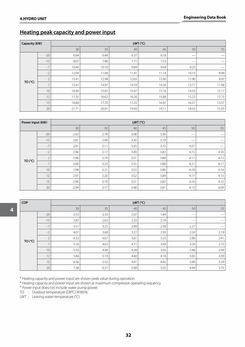
Heating peak capacity and power input
Capacity (kW) LWT (°C)
30 35 40 45 50 55
TO (°C)
-20 6.64 6.48 6.37 6.18 — —
-15 8.07 7.86 7.71 7.53 — —
-7 10.40 10.10 9.89 9.69 9.23 —
-2 12.04 11.68 11.41 11.18 10.73 8.99
2 13.41 12.98 12.65 12.40 11.90 9.97
7 15.47 14.97 14.59 14.30 13.71 11.48
10 16.40 15.87 15.47 15.16 14.53 12.17
12 17.35 16.62 16.20 15.88 15.22 12.75
15 18.84 17.70 17.25 16.91 16.21 13.57
20 21.71 20.01 19.50 19.11 18.33 15.35
Power input (kW) LWT (°C)
30 35 40 45 50 55
TO (°C)
-20 2.63 2.78 3.08 3.36 — —
-15 2.81 2.99 3.30 3.70 — —
-7 2.91 3.11 3.43 3.75 4.07 —
-2 2.96 3.17 3.49 3.82 4.15 4.10
2 2.96 3.19 3.51 3.84 4.17 4.13
7 3.00 3.23 3.55 3.88 4.21 4.17
10 2.98 3.21 3.53 3.86 4.18 4.14
12 2.97 3.20 3.52 3.84 4.17 4.13
15 2.96 3.19 3.51 3.83 4.16 4.12
20 2.94 3.17 3.48 3.81 4.13 4.09
COP LWT (°C)
30 35 40 45 50 55
TO (°C)
-20 2.53 2.33 2.07 1.84 — —
-15 2.87 2.63 2.33 2.19 — —
-7 3.57 3.25 2.89 2.58 2.27 —
-2 4.07 3.68 3.27 2.93 2.59 2.19
2 4.53 4.07 3.61 3.23 2.86 2.41
7 5.16 4.63 4.11 3.69 3.26 2.75
10 5.50 4.94 4.38 3.93 3.48 2.94
12 5.84 5.19 4.60 4.14 3.65 3.09
15 6.36 5.55 4.91 4.42 3.90 3.29
20 7.38 6.31 5.60 5.02 4.44 3.75
* Heating capacity and power input are shown peak value during operation* Heating capacity and power input are shown at maximum compressor operating requency* Power input does not include water pump power.TO : Outdoor temperature (DB°C) RH85%LWT : Leaving water temperature (°C)
32
4
4.HYDRO UNIT Engineering Data Book
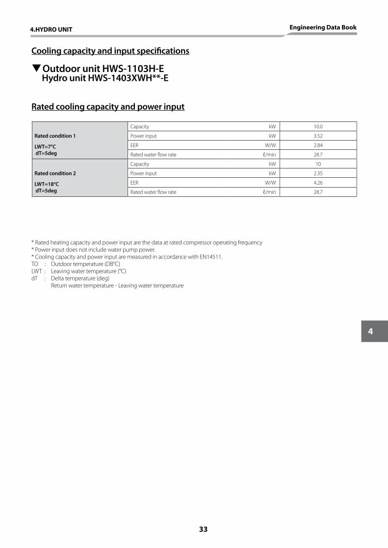
TOutdoor unit HWS-1103H-E Hydro unit HWS-1403XWH**-E
Rated cooling capacity and power input
Rated condition 1
Capacity kW 10.0
Power input kW 3.52
LWT=7°C dT=5deg
EER W/W 2.84
Rated water flow rate ℓ/min 28.7
Rated condition 2
Capacity kW 10
Power input kW 2.35
LWT=18°C dT=5deg
EER W/W 4.26
Rated water flow rate ℓ/min 28.7
* Rated heating capacity and power input are the data at rated compressor operating frequency* Power input does not include water pump power.* Cooling capacity and power input are measured in accordance with EN14511.TO : Outdoor temperature (DB°C) LWT : Leaving water temperature (°C)dT : Delta temperature (deg) Return water temperature - Leaving water temperature
Cooling capacity and input specifications
4.HYDRO UNIT Engineering Data Book
33
4
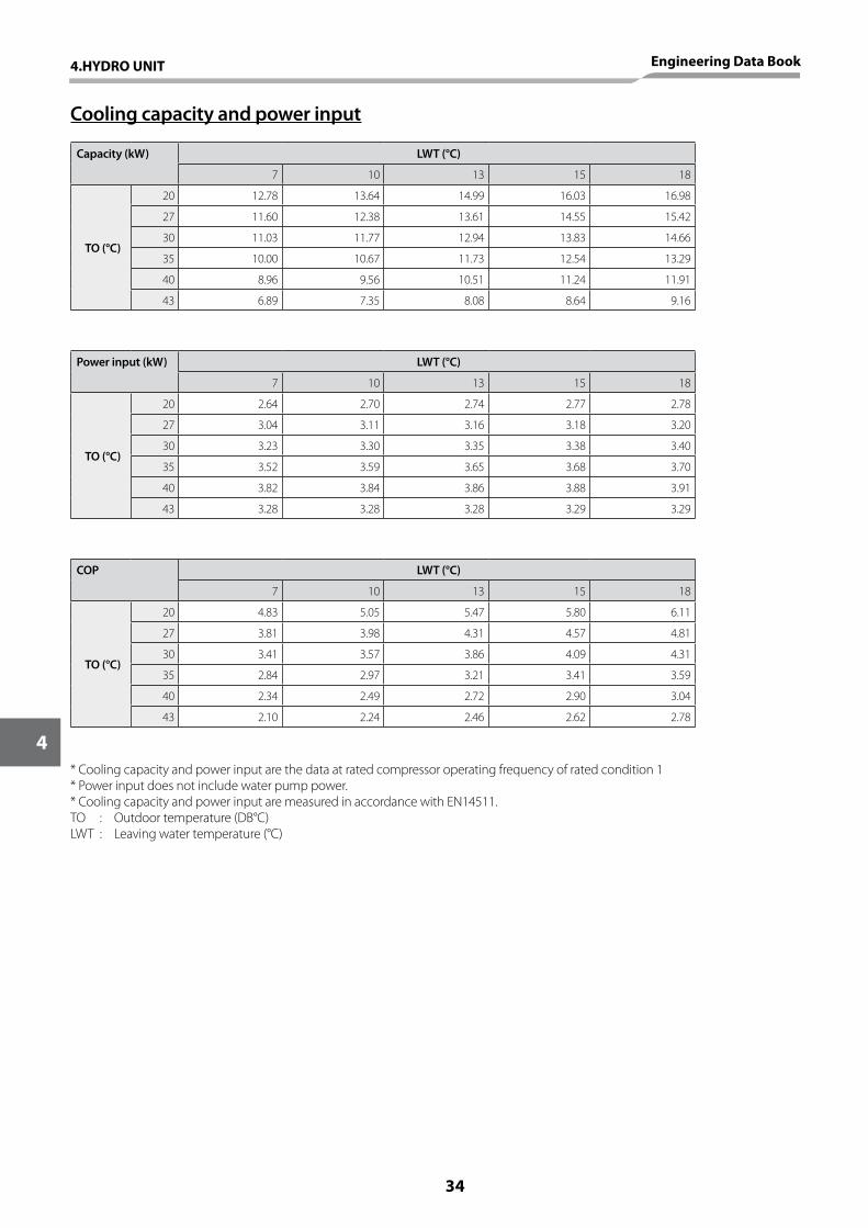
Cooling capacity and power input
Capacity (kW) LWT (°C)
7 10 13 15 18
TO (°C)
20 12.78 13.64 14.99 16.03 16.98
27 11.60 12.38 13.61 14.55 15.42
30 11.03 11.77 12.94 13.83 14.66
35 10.00 10.67 11.73 12.54 13.29
40 8.96 9.56 10.51 11.24 11.91
43 6.89 7.35 8.08 8.64 9.16
Power input (kW) LWT (°C)
7 10 13 15 18
TO (°C)
20 2.64 2.70 2.74 2.77 2.78
27 3.04 3.11 3.16 3.18 3.20
30 3.23 3.30 3.35 3.38 3.40
35 3.52 3.59 3.65 3.68 3.70
40 3.82 3.84 3.86 3.88 3.91
43 3.28 3.28 3.28 3.29 3.29
COP LWT (°C)
7 10 13 15 18
TO (°C)
20 4.83 5.05 5.47 5.80 6.11
27 3.81 3.98 4.31 4.57 4.81
30 3.41 3.57 3.86 4.09 4.31
35 2.84 2.97 3.21 3.41 3.59
40 2.34 2.49 2.72 2.90 3.04
43 2.10 2.24 2.46 2.62 2.78
* Cooling capacity and power input are the data at rated compressor operating frequency of rated condition 1* Power input does not include water pump power.* Cooling capacity and power input are measured in accordance with EN14511.TO : Outdoor temperature (DB°C) LWT : Leaving water temperature (°C)
34
4
4.HYDRO UNIT Engineering Data Book

TOutdoor unit HWS-1403H-E Hydro unit HWS-1403XWH**-E
Rated heating capacity and power input
Rated condition 1
Capacity kW 14.0
Power input kW 3.11
LWT=35°CdT=5deg
COP W/W 4.50
Rated water flow rate ℓ/min 40.1
Rated condition 2
Capacity kW 14.0
Power input kW 3.95
LWT=45°CdT=5deg
COP W/W 3.54
Rated water flow rate ℓ/min 40.1
* Rated heating capacity and power input are the data at rated compressor operating frequency* Power input does not include water pump power.* Heating capacity and power input are measured in accordance with EN14511.TO : Outdoor temperature (DB°C) RH85%LWT : Leaving water temperature (°C)dT : Delta temperature (deg) Leaving water temperature - return water temperature
Heating capacity and input specifications
4.HYDRO UNIT Engineering Data Book
35
4

Average heating capacity and power input
Capacity (kW) LWT (°C)
30 35 40 45 50 55
TO (°C)
-20 6.43 6.18 5.94 5.43 — —
-15 8.26 7.94 7.64 6.98 — —
-7 9.75 9.37 9.01 8.24 7.42 —
-2 11.37 10.93 10.52 9.61 8.66 8.15
2 12.03 11.56 11.12 10.17 9.16 8.62
7 17.77 17.08 16.43 15.02 13.53 12.13
10 18.66 17.93 17.25 15.77 14.21 12.74
12 19.92 18.96 18.24 16.67 15.02 13.47
15 21.53 20.09 19.33 17.67 15.91 14.27
20 23.89 21.87 21.04 19.23 17.32 15.53
Power input (kW) LWT (°C)
30 35 40 45 50 55
TO (°C)
-20 3.24 3.50 3.76 3.77 — —
-15 3.41 3.69 3.96 3.98 — —
-7 3.80 4.10 4.40 4.42 4.44 —
-2 3.74 4.04 4.34 4.36 4.38 4.41
2 3.69 3.98 4.27 4.29 4.31 4.34
7 3.65 3.94 4.23 4.25 4.27 4.30
10 3.65 3.94 4.23 4.25 4.27 4.30
12 3.66 3.95 4.24 4.26 4.28 4.31
15 3.69 3.98 4.28 4.30 4.32 4.35
20 3.48 3.75 4.03 4.05 4.07 4.10
COP LWT (°C)
30 35 40 45 50 55
TO (°C)
-20 1.98 1.77 1.58 1.44 — —
-15 2.42 2.15 1.93 1.75 — —
-7 2.57 2.29 2.05 1.86 1.67 —
-2 3.04 2.71 2.42 2.20 1.98 1.85
2 3.26 2.90 2.60 2.37 2.13 1.99
7 4.87 4.34 3.88 3.53 3.17 2.82
10 5.11 4.55 4.08 3.71 3.33 2.96
12 5.44 4.80 4.30 3.91 3.51 3.13
15 5.83 5.05 4.52 4.11 3.68 3.28
20 6.86 5.83 5.22 4.75 4.26 3.79
* Heating capacity and power input are include defrost cycle data.* Heating capacity and power input are shown at maximum operating frequency* Power input does not include water pump power.* Heating capacity and power input are measured in accordance with EN14511.TO : Outdoor temperature (DB°C) RH85%LWT : Leaving water temperature (°C)
36
4
4.HYDRO UNIT Engineering Data Book
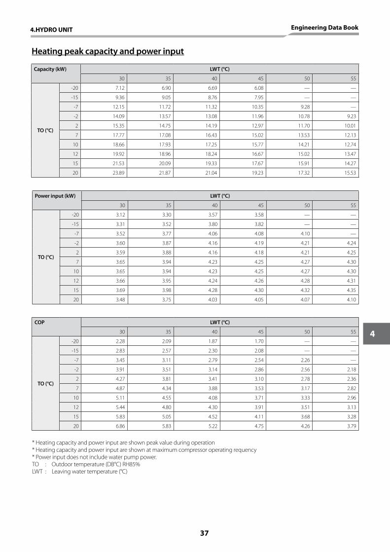
Heating peak capacity and power input
Capacity (kW) LWT (°C)
30 35 40 45 50 55
TO (°C)
-20 7.12 6.90 6.69 6.08 — —
-15 9.36 9.05 8.76 7.95 — —
-7 12.15 11.72 11.32 10.35 9.28 —
-2 14.09 13.57 13.08 11.96 10.78 9.23
2 15.35 14.75 14.19 12.97 11.70 10.01
7 17.77 17.08 16.43 15.02 13.53 12.13
10 18.66 17.93 17.25 15.77 14.21 12.74
12 19.92 18.96 18.24 16.67 15.02 13.47
15 21.53 20.09 19.33 17.67 15.91 14.27
20 23.89 21.87 21.04 19.23 17.32 15.53
Power input (kW) LWT (°C)
30 35 40 45 50 55
TO (°C)
-20 3.12 3.30 3.57 3.58 — —
-15 3.31 3.52 3.80 3.82 — —
-7 3.52 3.77 4.06 4.08 4.10 —
-2 3.60 3.87 4.16 4.19 4.21 4.24
2 3.59 3.88 4.16 4.18 4.21 4.25
7 3.65 3.94 4.23 4.25 4.27 4.30
10 3.65 3.94 4.23 4.25 4.27 4.30
12 3.66 3.95 4.24 4.26 4.28 4.31
15 3.69 3.98 4.28 4.30 4.32 4.35
20 3.48 3.75 4.03 4.05 4.07 4.10
COP LWT (°C)
30 35 40 45 50 55
TO (°C)
-20 2.28 2.09 1.87 1.70 — —
-15 2.83 2.57 2.30 2.08 — —
-7 3.45 3.11 2.79 2.54 2.26 —
-2 3.91 3.51 3.14 2.86 2.56 2.18
2 4.27 3.81 3.41 3.10 2.78 2.36
7 4.87 4.34 3.88 3.53 3.17 2.82
10 5.11 4.55 4.08 3.71 3.33 2.96
12 5.44 4.80 4.30 3.91 3.51 3.13
15 5.83 5.05 4.52 4.11 3.68 3.28
20 6.86 5.83 5.22 4.75 4.26 3.79
* Heating capacity and power input are shown peak value during operation* Heating capacity and power input are shown at maximum compressor operating requency* Power input does not include water pump power.TO : Outdoor temperature (DB°C) RH85%LWT : Leaving water temperature (°C)
4.HYDRO UNIT Engineering Data Book
37
4
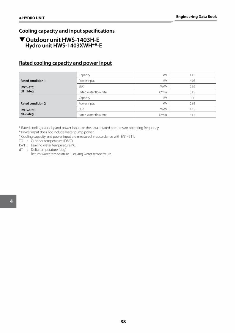
TOutdoor unit HWS-1403H-E Hydro unit HWS-1403XWH**-E
Rated cooling capacity and power input
Rated condition 1
Capacity kW 11.0
Power input kW 4.08
LWT=7°CdT=5deg
EER W/W 2.69
Rated water flow rate ℓ/min 31.5
Rated condition 2
Capacity kW 11
Power input kW 2.65
LWT=18°CdT=5deg
EER W/W 4.15
Rated water flow rate ℓ/min 31.5
* Rated cooling capacity and power input are the data at rated compressor operating frequency* Power input does not include water pump power.* Cooling capacity and power input are measured in accordance with EN14511.TO : Outdoor temperature (DB°C) LWT : Leaving water temperature (°C)dT : Delta temperature (deg) Return water temperature - Leaving water temperature
Cooling capacity and input specifications
38
4
4.HYDRO UNIT Engineering Data Book
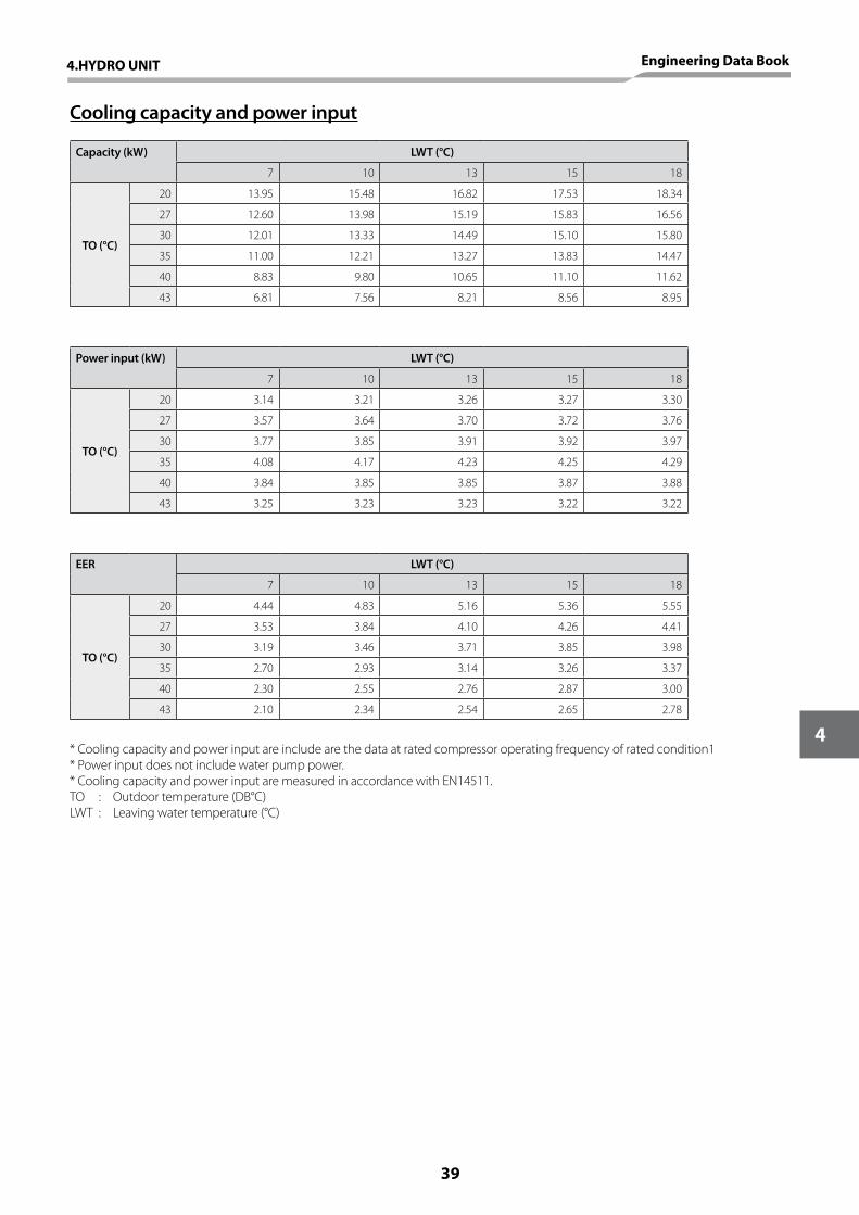
Cooling capacity and power input
Capacity (kW) LWT (°C)
7 10 13 15 18
TO (°C)
20 13.95 15.48 16.82 17.53 18.34
27 12.60 13.98 15.19 15.83 16.56
30 12.01 13.33 14.49 15.10 15.80
35 11.00 12.21 13.27 13.83 14.47
40 8.83 9.80 10.65 11.10 11.62
43 6.81 7.56 8.21 8.56 8.95
Power input (kW) LWT (°C)
7 10 13 15 18
TO (°C)
20 3.14 3.21 3.26 3.27 3.30
27 3.57 3.64 3.70 3.72 3.76
30 3.77 3.85 3.91 3.92 3.97
35 4.08 4.17 4.23 4.25 4.29
40 3.84 3.85 3.85 3.87 3.88
43 3.25 3.23 3.23 3.22 3.22
EER LWT (°C)
7 10 13 15 18
TO (°C)
20 4.44 4.83 5.16 5.36 5.55
27 3.53 3.84 4.10 4.26 4.41
30 3.19 3.46 3.71 3.85 3.98
35 2.70 2.93 3.14 3.26 3.37
40 2.30 2.55 2.76 2.87 3.00
43 2.10 2.34 2.54 2.65 2.78
* Cooling capacity and power input are include are the data at rated compressor operating frequency of rated condition1* Power input does not include water pump power.* Cooling capacity and power input are measured in accordance with EN14511.TO : Outdoor temperature (DB°C) LWT : Leaving water temperature (°C)
4.HYDRO UNIT Engineering Data Book
39
4
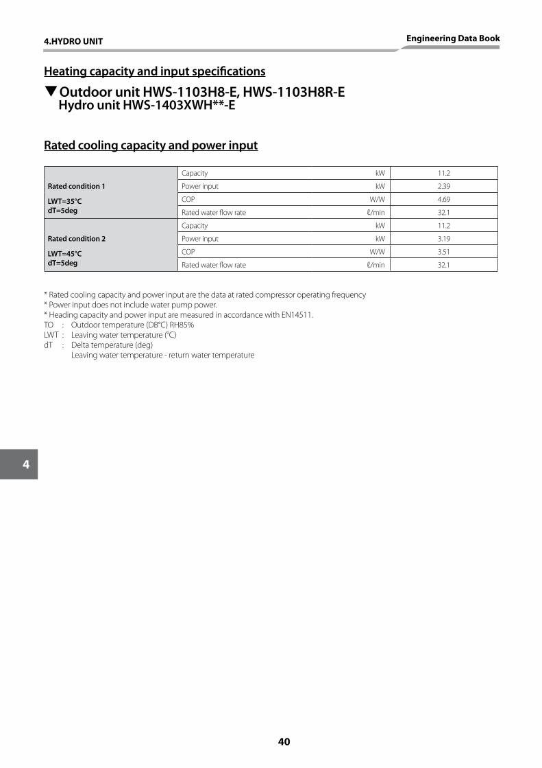
TOutdoor unit HWS-1103H8-E, HWS-1103H8R-E Hydro unit HWS-1403XWH**-E
Rated cooling capacity and power input
Rated condition 1
Capacity kW 11.2
Power input kW 2.39
LWT=35°CdT=5deg
COP W/W 4.69
Rated water flow rate ℓ/min 32.1
Rated condition 2
Capacity kW 11.2
Power input kW 3.19
LWT=45°CdT=5deg
COP W/W 3.51
Rated water flow rate ℓ/min 32.1
* Rated cooling capacity and power input are the data at rated compressor operating frequency* Power input does not include water pump power.* Heading capacity and power input are measured in accordance with EN14511.TO : Outdoor temperature (DB°C) RH85%LWT : Leaving water temperature (°C)dT : Delta temperature (deg) Leaving water temperature - return water temperature
Heating capacity and input specifications
40
4
4.HYDRO UNIT Engineering Data Book
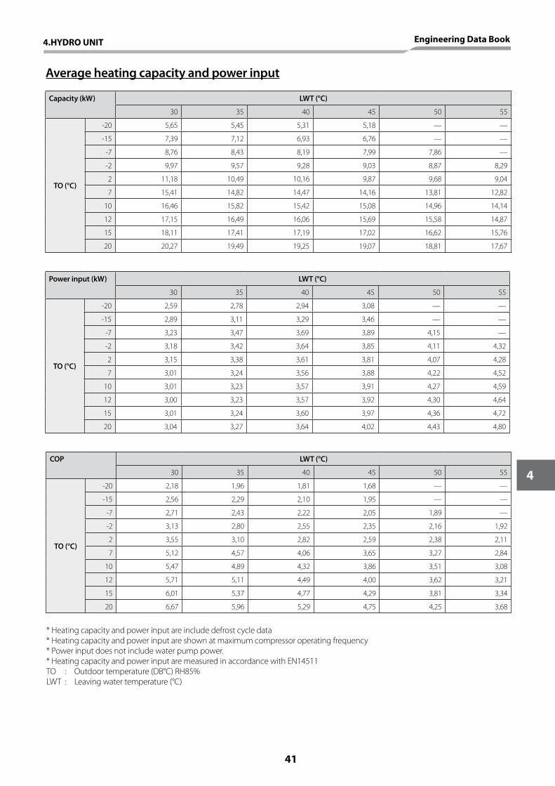
Average heating capacity and power input
Capacity (kW) LWT (°C)
30 35 40 45 50 55
TO (°C)
-20 5,65 5,45 5,31 5,18 — —
-15 7,39 7,12 6,93 6,76 — —
-7 8,76 8,43 8,19 7,99 7,86 —
-2 9,97 9,57 9,28 9,03 8,87 8,29
2 11,18 10,49 10,16 9,87 9,68 9,04
7 15,41 14,82 14,47 14,16 13,81 12,82
10 16,46 15,82 15,42 15,08 14,96 14,14
12 17,15 16,49 16,06 15,69 15,58 14,87
15 18,11 17,41 17,19 17,02 16,62 15,76
20 20,27 19,49 19,25 19,07 18,81 17,67
Power input (kW) LWT (°C)
30 35 40 45 50 55
TO (°C)
-20 2,59 2,78 2,94 3,08 — —
-15 2,89 3,11 3,29 3,46 — —
-7 3,23 3,47 3,69 3,89 4,15 —
-2 3,18 3,42 3,64 3,85 4,11 4,32
2 3,15 3,38 3,61 3,81 4,07 4,28
7 3,01 3,24 3,56 3,88 4,22 4,52
10 3,01 3,23 3,57 3,91 4,27 4,59
12 3,00 3,23 3,57 3,92 4,30 4,64
15 3,01 3,24 3,60 3,97 4,36 4,72
20 3,04 3,27 3,64 4,02 4,43 4,80
COP LWT (°C)
30 35 40 45 50 55
TO (°C)
-20 2,18 1,96 1,81 1,68 — —
-15 2,56 2,29 2,10 1,95 — —
-7 2,71 2,43 2,22 2,05 1,89 —
-2 3,13 2,80 2,55 2,35 2,16 1,92
2 3,55 3,10 2,82 2,59 2,38 2,11
7 5,12 4,57 4,06 3,65 3,27 2,84
10 5,47 4,89 4,32 3,86 3,51 3,08
12 5,71 5,11 4,49 4,00 3,62 3,21
15 6,01 5,37 4,77 4,29 3,81 3,34
20 6,67 5,96 5,29 4,75 4,25 3,68
* Heating capacity and power input are include defrost cycle data* Heating capacity and power input are shown at maximum compressor operating frequency* Power input does not include water pump power.* Heating capacity and power input are measured in accordance with EN14511TO : Outdoor temperature (DB°C) RH85%LWT : Leaving water temperature (°C)
4.HYDRO UNIT Engineering Data Book
41
4
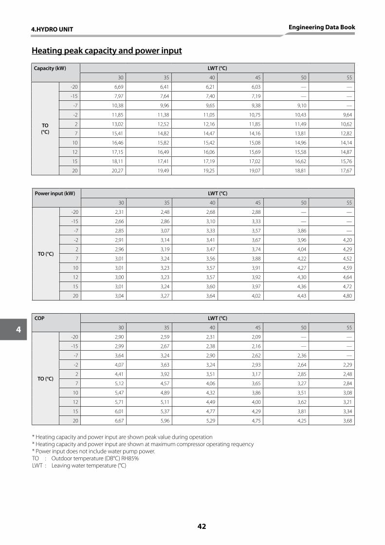
Heating peak capacity and power input
Capacity (kW) LWT (°C)
30 35 40 45 50 55
TO(°C)
-20 6,69 6,41 6,21 6,03 — —
-15 7,97 7,64 7,40 7,19 — —
-7 10,38 9,96 9,65 9,38 9,10 —
-2 11,85 11,38 11,05 10,75 10,43 9,64
2 13,02 12,52 12,16 11,85 11,49 10,62
7 15,41 14,82 14,47 14,16 13,81 12,82
10 16,46 15,82 15,42 15,08 14,96 14,14
12 17,15 16,49 16,06 15,69 15,58 14,87
15 18,11 17,41 17,19 17,02 16,62 15,76
20 20,27 19,49 19,25 19,07 18,81 17,67
Power input (kW) LWT (°C)
30 35 40 45 50 55
TO (°C)
-20 2,31 2,48 2,68 2,88 — —
-15 2,66 2,86 3,10 3,33 — —
-7 2,85 3,07 3,33 3,57 3,86 —
-2 2,91 3,14 3,41 3,67 3,96 4,20
2 2,96 3,19 3,47 3,74 4,04 4,29
7 3,01 3,24 3,56 3,88 4,22 4,52
10 3,01 3,23 3,57 3,91 4,27 4,59
12 3,00 3,23 3,57 3,92 4,30 4,64
15 3,01 3,24 3,60 3,97 4,36 4,72
20 3,04 3,27 3,64 4,02 4,43 4,80
COP LWT (°C)
30 35 40 45 50 55
TO (°C)
-20 2,90 2,59 2,31 2,09 — —
-15 2,99 2,67 2,38 2,16 — —
-7 3,64 3,24 2,90 2,62 2,36 —
-2 4,07 3,63 3,24 2,93 2,64 2,29
2 4,41 3,92 3,51 3,17 2,85 2,48
7 5,12 4,57 4,06 3,65 3,27 2,84
10 5,47 4,89 4,32 3,86 3,51 3,08
12 5,71 5,11 4,49 4,00 3,62 3,21
15 6,01 5,37 4,77 4,29 3,81 3,34
20 6,67 5,96 5,29 4,75 4,25 3,68
* Heating capacity and power input are shown peak value during operation* Heating capacity and power input are shown at maximum compressor operating requency* Power input does not include water pump power.TO : Outdoor temperature (DB°C) RH85%LWT : Leaving water temperature (°C)
42
4
4.HYDRO UNIT Engineering Data Book

Cooling capacity and input specifications
TOutdoor unit HWS-1103H8-E, HWS-1103H8R-E Hydro unit HWS-1403XWH**-E
Rated cooling capacity and power input
Rated condition 1
Capacity kW 10,0
Power input kW 3,52
LWT=7°CdT=5deg
EER W/W 2,84
Rated water flow rate ℓ/min 28,7
Rated condition 2
Capacity kW 10,0
Power input kW 2,14
LWT=18°CdT=5deg
EER W/W 4,67
Rated water flow rate ℓ/min 28,7
* Rated cooling capacity and power input are the data at rated compressor operating frequency* Power input does not include water pump power.* Cooling capacity and power input are measured in accordance with EN14511.TO : Outdoor temperature (DB°C) LWT : Leaving water temperature (°C)dT : Delta temperature (deg) Return water temperature - Leaving water temperature
4.HYDRO UNIT Engineering Data Book
43
4
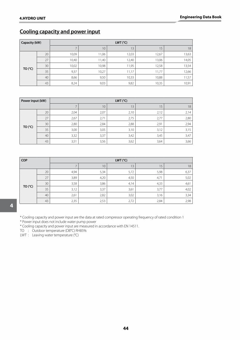
Cooling capacity and power input
Capacity (kW) LWT (°C)
7 10 13 15 18
TO (°C)
20 10,09 11,06 12,03 12,67 13,63
27 10,40 11,40 12,40 13,06 14,05
30 10,02 10,98 11,95 12,58 13,54
35 9,37 10,27 11,17 11,77 12,66
40 8,66 9,50 10,33 10,88 11,57
43 8,24 9,03 9,82 10,35 10,91
Power input (kW) LWT (°C)
7 10 13 15 18
TO (°C)
20 2,04 2,07 2,10 2,12 2,14
27 2,67 2,71 2,75 2,77 2,80
30 2,80 2,84 2,88 2,91 2,94
35 3,00 3,05 3,10 3,12 3,15
40 3,32 3,37 3,42 3,45 3,47
43 3,51 3,56 3,62 3,64 3,66
COP LWT (°C)
7 10 13 15 18
TO (°C)
20 4,94 5,34 5,72 5,98 6,37
27 3,89 4,20 4,50 4,71 5,02
30 3,58 3,86 4,14 4,33 4,61
35 3,12 3,37 3,61 3,77 4,02
40 2,61 2,82 3,02 3,16 3,34
43 2,35 2,53 2,72 2,84 2,98
* Cooling capacity and power input are the data at rated compressor operating frequency of rated condition 1* Power input does not include water pump power* Cooling capacity and power input are measured in accordance with EN 14511.TO : Outdoor temperature (DB°C) RH85%LWT : Leaving water temperature (°C)
44
4
4.HYDRO UNIT Engineering Data Book
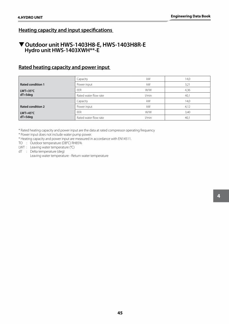
Heating capacity and input specifications
TOutdoor unit HWS-1403H8-E, HWS-1403H8R-E Hydro unit HWS-1403XWH**-E
Rated heating capacity and power input
Rated condition 1
Capacity kW 14,0
Power input kW 3,21
LWT=35°CdT=5deg
EER W/W 4,36
Rated water flow rate l/min 40,1
Rated condition 2
Capacity kW 14,0
Power input kW 4,12
LWT=45°CdT=5deg
EER W/W 3,40
Rated water flow rate l/min 40,1
* Rated heating capacity and power input are the data at rated compressor operating frequency* Power input does not include water pump power.* Heating capacity and power input are measured in accordance with EN14511.TO : Outdoor temperature (DB°C) RH85%LWT : Leaving water temperature (°C)dT : Delta temperature (deg) Leaving water temperature - Return water temperature
4.HYDRO UNIT Engineering Data Book
45
4
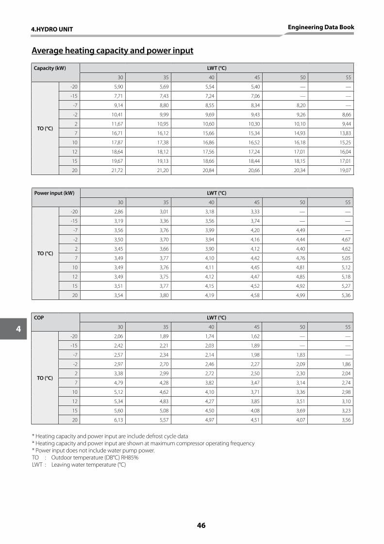
Average heating capacity and power input
Capacity (kW) LWT (°C)
30 35 40 45 50 55
TO (°C)
-20 5,90 5,69 5,54 5,40 — —
-15 7,71 7,43 7,24 7,06 — —
-7 9,14 8,80 8,55 8,34 8,20 —
-2 10,41 9,99 9,69 9,43 9,26 8,66
2 11,67 10,95 10,60 10,30 10,10 9,44
7 16,71 16,12 15,66 15,34 14,93 13,83
10 17,87 17,38 16,86 16,52 16,18 15,25
12 18,64 18,12 17,56 17,24 17,01 16,04
15 19,67 19,13 18,66 18,44 18,15 17,01
20 21,72 21,20 20,84 20,66 20,34 19,07
Power input (kW) LWT (°C)
30 35 40 45 50 55
TO (°C)
-20 2,86 3,01 3,18 3,33 — —
-15 3,19 3,36 3,56 3,74 — —
-7 3,56 3,76 3,99 4,20 4,49 —
-2 3,50 3,70 3,94 4,16 4,44 4,67
2 3,45 3,66 3,90 4,12 4,40 4,62
7 3,49 3,77 4,10 4,42 4,76 5,05
10 3,49 3,76 4,11 4,45 4,81 5,12
12 3,49 3,75 4,12 4,47 4,85 5,18
15 3,51 3,77 4,15 4,52 4,92 5,27
20 3,54 3,80 4,19 4,58 4,99 5,36
COP LWT (°C)
30 35 40 45 50 55
TO (°C)
-20 2,06 1,89 1,74 1,62 — —
-15 2,42 2,21 2,03 1,89 — —
-7 2,57 2,34 2,14 1,98 1,83 —
-2 2,97 2,70 2,46 2,27 2,09 1,86
2 3,38 2,99 2,72 2,50 2,30 2,04
7 4,79 4,28 3,82 3,47 3,14 2,74
10 5,12 4,62 4,10 3,71 3,36 2,98
12 5,34 4,83 4,27 3,85 3,51 3,10
15 5,60 5,08 4,50 4,08 3,69 3,23
20 6,13 5,57 4,97 4,51 4,07 3,56
* Heating capacity and power input are include defrost cycle data* Heating capacity and power input are shown at maximum compressor operating frequency* Power input does not include water pump power.TO : Outdoor temperature (DB°C) RH85%LWT : Leaving water temperature (°C)
46
4
4.HYDRO UNIT Engineering Data Book
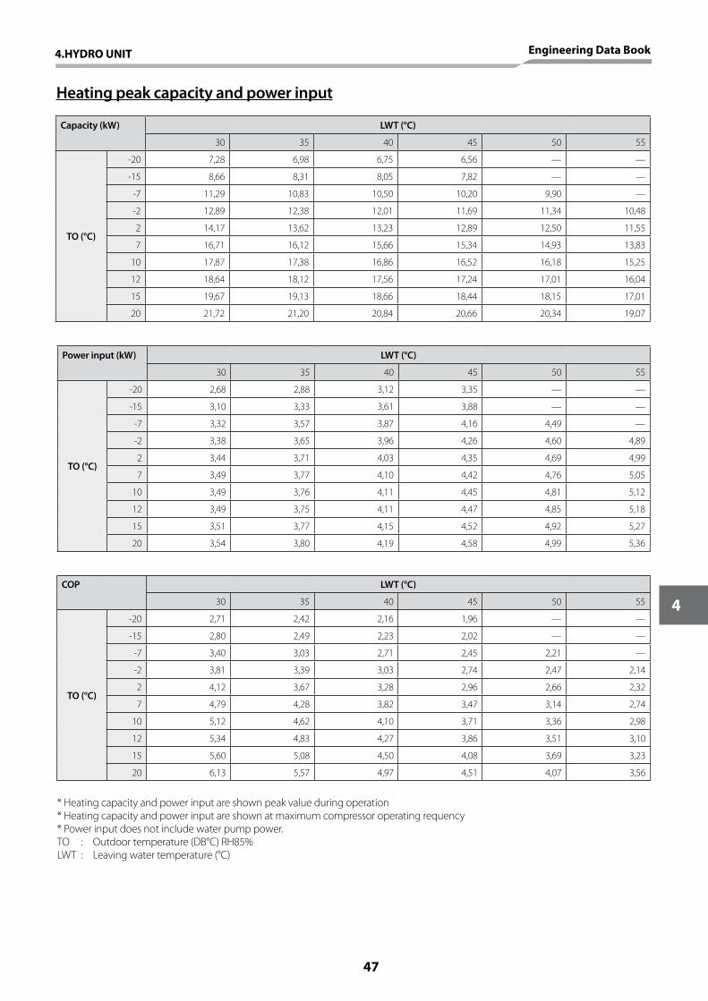
Heating peak capacity and power input
Capacity (kW) LWT (°C)
30 35 40 45 50 55
TO (°C)
-20 7,28 6,98 6,75 6,56 — —
-15 8,66 8,31 8,05 7,82 — —
-7 11,29 10,83 10,50 10,20 9,90 —
-2 12,89 12,38 12,01 11,69 11,34 10,48
2 14,17 13,62 13,23 12,89 12,50 11,55
7 16,71 16,12 15,66 15,34 14,93 13,83
10 17,87 17,38 16,86 16,52 16,18 15,25
12 18,64 18,12 17,56 17,24 17,01 16,04
15 19,67 19,13 18,66 18,44 18,15 17,01
20 21,72 21,20 20,84 20,66 20,34 19,07
Power input (kW) LWT (°C)
30 35 40 45 50 55
TO (°C)
-20 2,68 2,88 3,12 3,35 — —
-15 3,10 3,33 3,61 3,88 — —
-7 3,32 3,57 3,87 4,16 4,49 —
-2 3,38 3,65 3,96 4,26 4,60 4,89
2 3,44 3,71 4,03 4,35 4,69 4,99
7 3,49 3,77 4,10 4,42 4,76 5,05
10 3,49 3,76 4,11 4,45 4,81 5,12
12 3,49 3,75 4,11 4,47 4,85 5,18
15 3,51 3,77 4,15 4,52 4,92 5,27
20 3,54 3,80 4,19 4,58 4,99 5,36
COP LWT (°C)
30 35 40 45 50 55
TO (°C)
-20 2,71 2,42 2,16 1,96 — —
-15 2,80 2,49 2,23 2,02 — —
-7 3,40 3,03 2,71 2,45 2,21 —
-2 3,81 3,39 3,03 2,74 2,47 2,14
2 4,12 3,67 3,28 2,96 2,66 2,32
7 4,79 4,28 3,82 3,47 3,14 2,74
10 5,12 4,62 4,10 3,71 3,36 2,98
12 5,34 4,83 4,27 3,86 3,51 3,10
15 5,60 5,08 4,50 4,08 3,69 3,23
20 6,13 5,57 4,97 4,51 4,07 3,56
* Heating capacity and power input are shown peak value during operation* Heating capacity and power input are shown at maximum compressor operating requency* Power input does not include water pump power.TO : Outdoor temperature (DB°C) RH85%LWT : Leaving water temperature (°C)
4.HYDRO UNIT Engineering Data Book
47
4

Cooling capacity and input specifications
TOutdoor unit HWS-1403H8-E, HWS-1403H8R-E Hydro unit HWS-1403XWH**-E
Rated heating capacity and power input
Rated condition 1
Capacity kW 11,0
Power input kW 4,08
LWT=7°CdT=5deg
EER W/W 2,70
Rated water flow rate l/min 31,5
Rated condition 2
Capacity kW 11,0
Power input kW 2,43
LWT=18°CdT=5deg
EER W/W 4,53
Rated water flow rate l/min 31,5
* Rated cooling capacity and power input are the data at rated compressor operating frequency* Power input does not include water pump power.* Cooling capacity and power input are measured in accordance with EN 14511.TO : Outdoor temperature (DB°C) LWT : Leaving water temperature (°C)dT : Delta temperature (deg) Return water temperature - Leaving water temperature
48
4
4.HYDRO UNIT Engineering Data Book
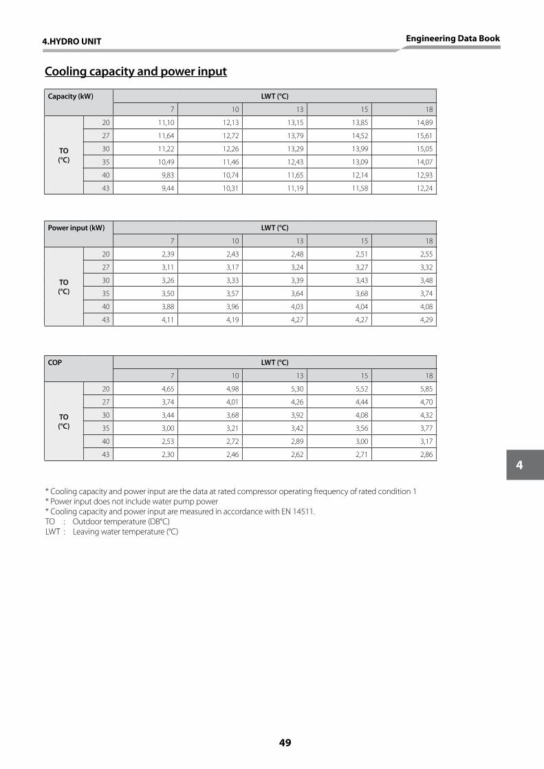
Cooling capacity and power input
Capacity (kW) LWT (°C)
7 10 13 15 18
TO(°C)
20 11,10 12,13 13,15 13,85 14,89
27 11,64 12,72 13,79 14,52 15,61
30 11,22 12,26 13,29 13,99 15,05
35 10,49 11,46 12,43 13,09 14,07
40 9,83 10,74 11,65 12,14 12,93
43 9,44 10,31 11,19 11,58 12,24
Power input (kW) LWT (°C)
7 10 13 15 18
TO(°C)
20 2,39 2,43 2,48 2,51 2,55
27 3,11 3,17 3,24 3,27 3,32
30 3,26 3,33 3,39 3,43 3,48
35 3,50 3,57 3,64 3,68 3,74
40 3,88 3,96 4,03 4,04 4,08
43 4,11 4,19 4,27 4,27 4,29
COP LWT (°C)
7 10 13 15 18
TO(°C)
20 4,65 4,98 5,30 5,52 5,85
27 3,74 4,01 4,26 4,44 4,70
30 3,44 3,68 3,92 4,08 4,32
35 3,00 3,21 3,42 3,56 3,77
40 2,53 2,72 2,89 3,00 3,17
43 2,30 2,46 2,62 2,71 2,86
* Cooling capacity and power input are the data at rated compressor operating frequency of rated condition 1* Power input does not include water pump power* Cooling capacity and power input are measured in accordance with EN 14511.TO : Outdoor temperature (DB°C)LWT : Leaving water temperature (°C)
4.HYDRO UNIT Engineering Data Book
49
4
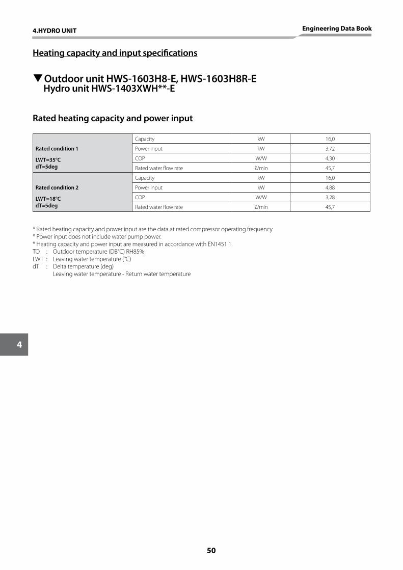
Heating capacity and input specifications
TOutdoor unit HWS-1603H8-E, HWS-1603H8R-E Hydro unit HWS-1403XWH**-E
Rated heating capacity and power input
Rated condition 1
Capacity kW 16,0
Power input kW 3,72
LWT=35°C dT=5deg
COP W/W 4,30
Rated water flow rate ℓ/min 45,7
Rated condition 2
Capacity kW 16,0
Power input kW 4,88
LWT=18°C dT=5deg
COP W/W 3,28
Rated water flow rate ℓ/min 45,7
* Rated heating capacity and power input are the data at rated compressor operating frequency * Power input does not include water pump power.* Heating capacity and power input are measured in accordance with EN1451 1.TO : Outdoor temperature (DB°C) RH85%LWT : Leaving water temperature (°C)dT : Delta temperature (deg) Leaving water temperature - Return water temperature
50
4
4.HYDRO UNIT Engineering Data Book
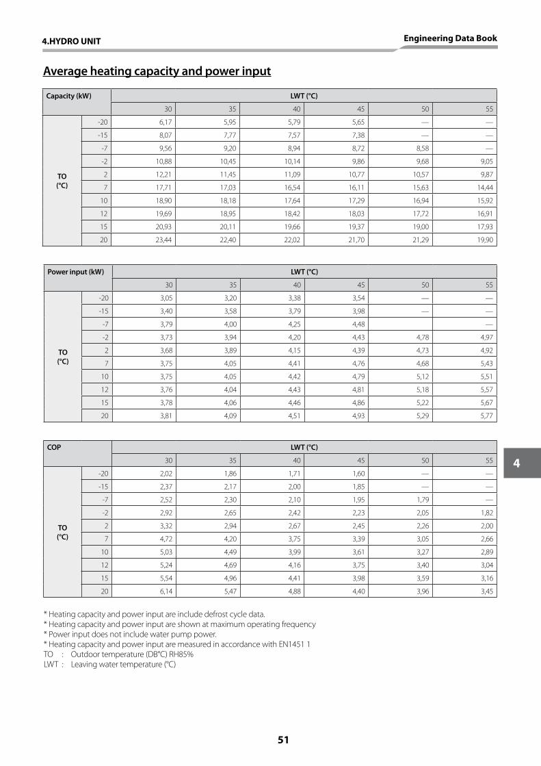
Average heating capacity and power input
Capacity (kW) LWT (°C)
30 35 40 45 50 55
TO(°C)
-20 6,17 5,95 5,79 5,65 — —
-15 8,07 7,77 7,57 7,38 — —
-7 9,56 9,20 8,94 8,72 8,58 —
-2 10,88 10,45 10,14 9,86 9,68 9,05
2 12,21 11,45 11,09 10,77 10,57 9,87
7 17,71 17,03 16,54 16,11 15,63 14,44
10 18,90 18,18 17,64 17,29 16,94 15,92
12 19,69 18,95 18,42 18,03 17,72 16,91
15 20,93 20,11 19,66 19,37 19,00 17,93
20 23,44 22,40 22,02 21,70 21,29 19,90
Power input (kW) LWT (°C)
30 35 40 45 50 55
TO(°C)
-20 3,05 3,20 3,38 3,54 — —
-15 3,40 3,58 3,79 3,98 — —
-7 3,79 4,00 4,25 4,48 —
-2 3,73 3,94 4,20 4,43 4,78 4,97
2 3,68 3,89 4,15 4,39 4,73 4,92
7 3,75 4,05 4,41 4,76 4,68 5,43
10 3,75 4,05 4,42 4,79 5,12 5,51
12 3,76 4,04 4,43 4,81 5,18 5,57
15 3,78 4,06 4,46 4,86 5,22 5,67
20 3,81 4,09 4,51 4,93 5,29 5,77
COP LWT (°C)
30 35 40 45 50 55
TO(°C)
-20 2,02 1,86 1,71 1,60 — —
-15 2,37 2,17 2,00 1,85 — —
-7 2,52 2,30 2,10 1,95 1,79 —
-2 2,92 2,65 2,42 2,23 2,05 1,82
2 3,32 2,94 2,67 2,45 2,26 2,00
7 4,72 4,20 3,75 3,39 3,05 2,66
10 5,03 4,49 3,99 3,61 3,27 2,89
12 5,24 4,69 4,16 3,75 3,40 3,04
15 5,54 4,96 4,41 3,98 3,59 3,16
20 6,14 5,47 4,88 4,40 3,96 3,45
* Heating capacity and power input are include defrost cycle data.* Heating capacity and power input are shown at maximum operating frequency* Power input does not include water pump power.* Heating capacity and power input are measured in accordance with EN1451 1TO : Outdoor temperature (DB°C) RH85%LWT : Leaving water temperature (°C)
4.HYDRO UNIT Engineering Data Book
51
4

Heating peak capacity and power input
Capacity (kW) LWT (°C)
30 35 40 45 50 55
TO(°C)
-20 7,69 7,37 7,13 6,93 — —
-15 9,15 8,78 8,50 8,26 — —
-7 11,92 11,44 11,09 10,78 10,46 —
-2 13,61 13,08 12,69 12,35 11,98 11,07
2 14,97 14,39 13,98 13,61 13,21 12,20
7 17,71 17,03 16,54 16,11 15,63 14,44
10 18,90 18,18 17,64 17,29 16,94 15,92
12 19,69 18,95 18,42 18,03 17,72 16,91
15 20,93 20,11 19,66 19,37 19,00 17,93
20 23,44 22,40 22,02 21,70 21,29 19,90
Power input (kW) LWT (°C)
30 35 40 45 50 55
TO(°C)
-20 2,89 3,10 3,36 3,60 — —
-15 3,33 3,58 3,88 4,17 — —
-7 3,57 3,84 4,16 4,47 4,83 —
-2 3,64 3,92 4,26 4,59 4,95 5,26
2 3,70 3,99 4,34 4,68 5,05 5,37
7 3,75 4,05 4,41 4,76 5,12 5,43
10 3,75 4,05 4,42 4,79 5,18 5,51
12 3,75 4,04 4,43 4,81 5,22 5,57
15 3,78 4,06 4,46 4,86 5,29 5,67
20 3,81 4,09 4,51 4,93 5,37 5,77
COP LWT (°C)
30 35 40 45 50 55
TO(°C)
-20 2,67 2,38 2,13 1,92 — —
-15 2,75 2,45 2,19 1,98 — —
-7 3,34 2,98 2,66 2,41 2,17 —
-2 3,74 3,33 2,98 2,69 2,42 2,10
2 4,05 3,60 3,22 2,91 2,62 2,27
7 4,72 4,20 3,75 3,39 3,05 2,66
10 5,03 4,49 3,99 3,61 3,27 2,89
12 5,24 4,69 4,16 3,75 3,40 3,04
15 5,54 4,96 4,41 3,98 3,59 3,16
20 6,14 5,47 4,88 4,40 3,96 3,45
* Heating capacity and power input are shown peak value during operation* Heating capacity and power input are shown at maximum compressor operating requency* Power input does not include water pump power.TO : Outdoor temperature (DB°C) RH85%LWT : Leaving water temperature (°C)
52
4
4.HYDRO UNIT Engineering Data Book

Cooling capacity and input specifications
TOutdoor unit HWS-1603H8-E, HWS-1603H8R-E Hydro unit HWS-1403XWH**-E
Rated cooling capacity and power input
Rated condition 1
Capacity kW 13,0
Power input kW 4,80
LWT=7°CdT=5deg
EER W/W 2,71
Rated water flow rate ℓ/min 37,2
Rated condition 2
Capacity kW 13,0
Power input kW 3,08
LWT=18°CdT=5deg
EER W/W 4,22
Rated water flow rate ℓ/min 37,2
* Rated cooling capacity and power input are the data at rated compressor operating frequency* Power input does not include water pump power.* Cooling capacity and power input are measured in accordance with EN 14511.TO : Outdoor temperature (DB°C) LWT : Leaving water temperature (°C)dT : Delta temperature (deg) Return water temperature - Leaving water temperature
4.HYDRO UNIT Engineering Data Book
53
4
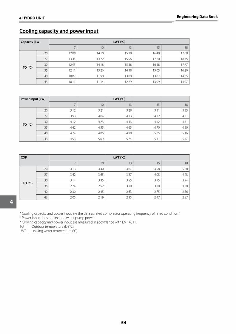
Cooling capacity and power input
Capacity (kW) LWT (°C)
7 10 13 15 18
TO (°C)
20 12,88 14,10 15,29 16,49 17,68
27 13,44 14,72 15,96 17,20 18,45
30 12,95 14,18 15,38 16,58 17,77
35 12,11 13,26 14,38 15,05 16,20
40 10,87 11,90 13,08 13,87 14,75
43 10,11 11,14 12,29 13,09 14,07
Power input (kW) LWT (°C)
7 10 13 15 18
TO (°C)
20 3,12 3,21 3,28 3,31 3,35
27 3,93 4,04 4,13 4,22 4,31
30 4,12 4,23 4,33 4,42 4,51
35 4,42 4,55 4,65 4,70 4,80
40 4,74 4,86 4,98 5,05 5,16
43 4,93 5,09 5,24 5,31 5,47
COP LWT (°C)
7 10 13 15 18
TO (°C)
20 4,13 4,40 4,67 4,98 5,28
27 3,42 3,65 3,87 4,08 4,28
30 3,14 3,35 3,55 3,75 3,94
35 2,74 2,92 3,10 3,20 3,38
40 2,30 2,45 2,63 2,75 2,86
43 2,05 2,19 2,35 2,47 2,57
* Cooling capacity and power input are the data at rated compressor operating frequency of rated condition 1* Power input does not include water pump power.* Cooling capacity and power input are measured in accordance with EN 14511.TO : Outdoor temperature (DB°C)LWT : Leaving water temperature (°C)
54
4
4.HYDRO UNIT Engineering Data Book
010 15 20 25 30
1
2
3
4
5
6
7
8
SW1
SW2
SW3
230V
220V230V
220V
230V
220V
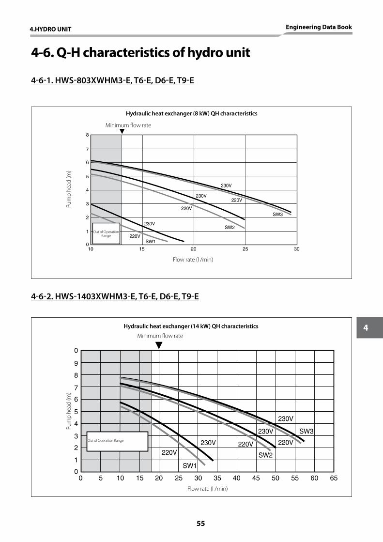
4-6. Q-H characteristics of hydro unit
4-6-1. HWS-803XWHM3-E, T6-E, D6-E, T9-E
4-6-2. HWS-1403XWHM3-E, T6-E, D6-E, T9-E
00 5 10 15 20 25 30 35 40 45 50 55 60 65
1
2
3
4
5
6
7
8
9
10
SW1
SW2
SW3
230V
220V
230V
220V230V220V
Hydraulic heat exchanger (8 kW) QH characteristics
Hydraulic heat exchanger (14 kW) QH characteristics
Flow rate (l /min)
Flow rate (l /min)
Out of Operation Range
Out of Operation Range
Minimum flow rate
Minimum flow rate
Pum
p he
ad (m
)Pu
mp
head
(m)
4.HYDRO UNIT Engineering Data Book
55
4
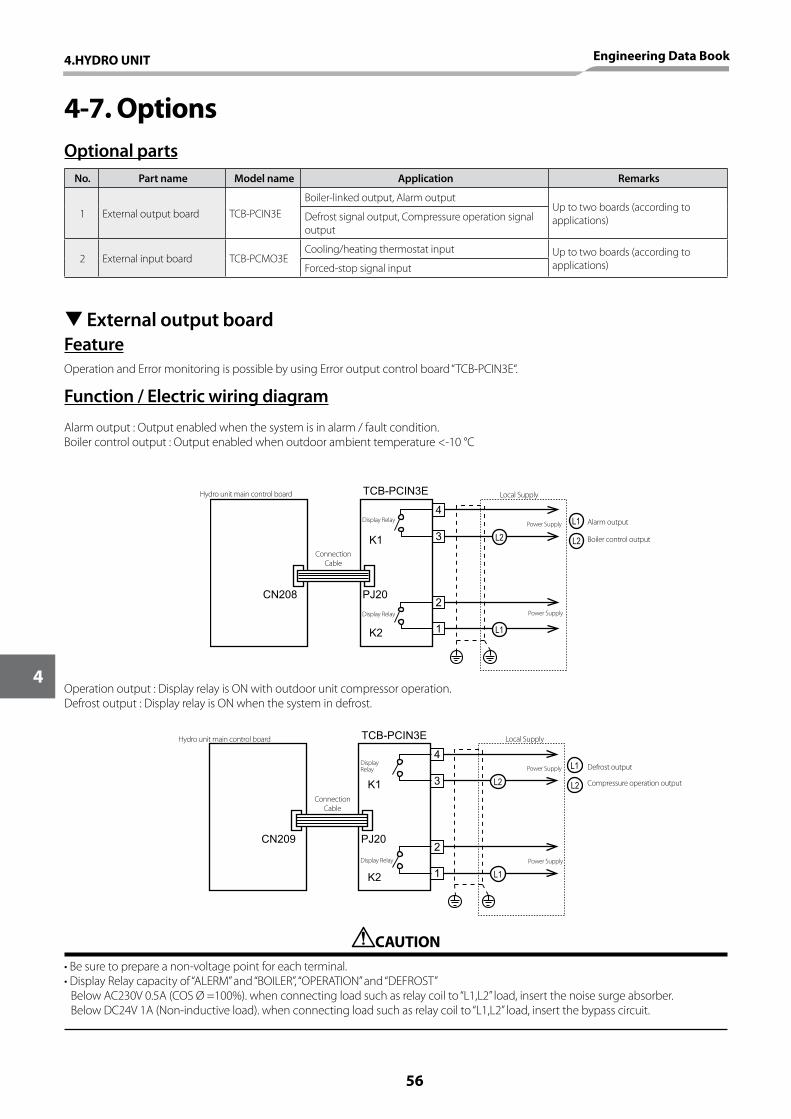
4-7. OptionsOptional parts
FeatureOperation and Error monitoring is possible by using Error output control board “TCB-PCIN3E“.
Function / Electric wiring diagram
Alarm output : Output enabled when the system is in alarm / fault condition.Boiler control output : Output enabled when outdoor ambient temperature <-10 °C
No. Part name Model name Application Remarks
1 External output board TCB-PCIN3EBoiler-linked output, Alarm output
Up to two boards (according to applications)Defrost signal output, Compressure operation signal
output
2 External input board TCB-PCMO3ECooling/heating thermostat input Up to two boards (according to
applications)Forced-stop signal input
TExternal output board
TCB-PCIN3E
4
2
3
1
PJ20CN208
K2
K1 L2
L1
L2
L1
Operation output : Display relay is ON with outdoor unit compressor operation.Defrost output : Display relay is ON when the system in defrost.
CAUTION•Besuretoprepareanon-voltagepointforeachterminal.•DisplayRelaycapacityof“ALERM”and“BOILER”,“OPERATION”and“DEFROST” Below AC230V 0.5A (COS Ø =100%). when connecting load such as relay coil to “L1,L2” load, insert the noise surge absorber. Below DC24V 1A (Non-inductive load). when connecting load such as relay coil to “L1,L2” load, insert the bypass circuit.
TCB-PCIN3E
4
2
3
1
PJ20CN209
K2
K1 L2
L1
L2
L1
Local SupplyHydro unit main control board
Power Supply
Power Supply
Alarm output
Defrost output
Boiler control output
Compressure operation output
Display Relay
Display Relay
Connection Cable
Hydro unit main control board
Connection Cable
Local Supply
Power Supply
Power SupplyDisplay Relay
Display Relay
56
4
4.HYDRO UNIT Engineering Data Book

1
2
3PJ17CN211
TCB-PCMO3E
COM
TCB-PCMO3E
1
2
3
PJ17CN210 S2
COM
Feature
* “TCB-PCMO3E“ is used for the following external master controls.1. Room thermostat input2. Emergency shutdown inputRefer to “Function/Electric wiring diagram“ for feature of each control because connection is different according to the control.
Function / Electric wiring diagram
Room thermostat input2-3 : Room thermostat input for cooling mode1-3 : Room thermostat input for heating mode•Outputenabledwheneitherheatingorcoolingmodeselectedonroomthermostat.(locallyprocured)•Voltfreedetails:•Connectiondetails:Cooling connection : Terminals 3 (COM) and 2 (COOL) on TCB-BCMO3E (See Schematic below)Heating connection : Terminals 3 (COM) and 1 (HEAT) on TCB-BCMO3E (See Schematic below)
TExternal input board
Emergency shutdown inputS2 : Cylinder thermostat input•Non-voltagecontacts•Connectiondetails: Emergency stop : Terminals 3 (COM) and 1 (HEAT) on TCB-PCMO3E (See Schematic below)
CAUTION•Besuretopreparenonvoltagecontinuouspointofcontactforeachterminal.•SupplementaryInsulationmustbeaddedtousertouchedtousertouchabelpartofswitches.
Connection Cable
Connection Cable
Thermostat (locally procured)
Cool
Hot
Locally procured
Cooling Heating
on off on off
2-3 open close - -
1-3 - - open close
Thermostat operation
COOL
HEAT
COOL
HEAT
4.HYDRO UNIT Engineering Data Book
57
4

5. OUTDOOR UNIT
58
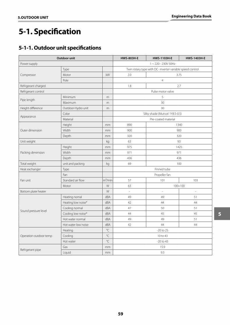
5-1. Specification
5-1-1. Outdoor unit specifications
Outdoor unit HWS-803H-E HWS-1103H-E HWS-1403H-E
Power supply 1 ~ 220 - 230V 50Hz
Compressor
Type Twin rotary type with DC- inverter variable speed control
Motor kW 2.0 3.75
Pole 4
Refrigerant charged 1.8 2.7
Refrigerant control Pulse motor valve
Pipe lengthMinimum m 5
Maximum m 30
Height difference Outdoor-Hydro unit m 30
AppearanceColor Silky shade (Muncel 1Y8.5-0.5)
Material Pre-coated material
Outer dimension
Height mm 890 1340
Width mm 900 900
Depth mm 320 320
Unit weight kg 63 93
Packing dimension
Height mm 975 1425
Width mm 971 971
Depth mm 436 436
Total weight unit and packing kg 69 100
Heat exchanger Type Finned tube
Fan unit
Fan Propeller fan
Standard air flow m³/min 57 101 103
Motor W 63 100+100
Bottom plate heater W - - -
Sound pressure level
Heating nomal dBA 49 49 51
Heating low noise* dBA 42 44 44
Cooling normal dBA 47 50 51
Cooling low noise* dBA 44 45 45
Hot water normal dBA 49 49 51
Hot water low noise dBA 42 44 44
Operation outdoor temp
Heating °C -20 to 25
Cooling °C 10 to 43
Hot water °C -20 to 43
Refrigerant pipeGas mm 15.9
Liquid mm 9.5
5.OUTDOOR UNIT Engineering Data Book
59
5
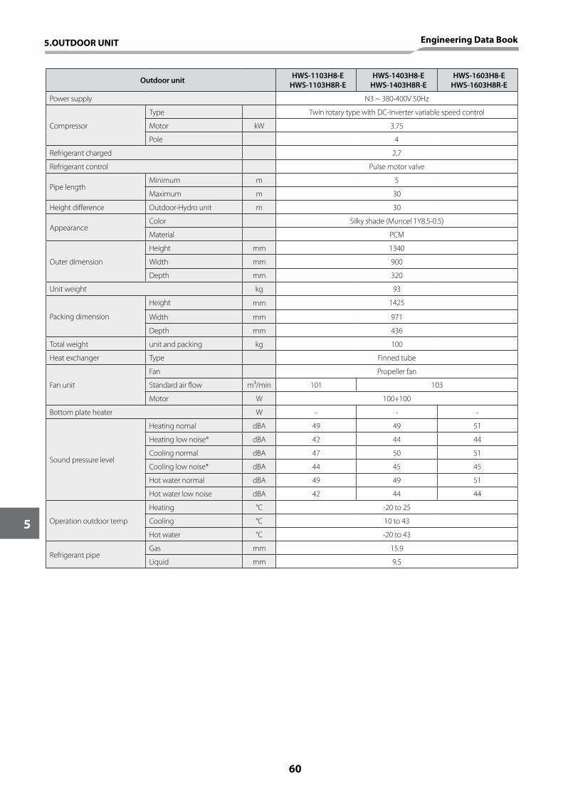
Outdoor unit HWS-1103H8-EHWS-1103H8R-E
HWS-1403H8-EHWS-1403H8R-E
HWS-1603H8-EHWS-1603H8R-E
Power supply N3 ~ 380-400V 50Hz
Compressor
Type Twin rotary type with DC-Inverter variable speed control
Motor kW 3.75
Pole 4
Refrigerant charged 2.7
Refrigerant control Pulse motor valve
Pipe lengthMinimum m 5
Maximum m 30
Height difference Outdoor-Hydro unit m 30
AppearanceColor Silky shade (Muncel 1Y8.5-0.5)
Material PCM
Outer dimension
Height mm 1340
Width mm 900
Depth mm 320
Unit weight kg 93
Packing dimension
Height mm 1425
Width mm 971
Depth mm 436
Total weight unit and packing kg 100
Heat exchanger Type Finned tube
Fan unit
Fan Propeller fan
Standard air flow m³/min 101 103
Motor W 100+100
Bottom plate heater W - - -
Sound pressure level
Heating nomal dBA 49 49 51
Heating low noise* dBA 42 44 44
Cooling normal dBA 47 50 51
Cooling low noise* dBA 44 45 45
Hot water normal dBA 49 49 51
Hot water low noise dBA 42 44 44
Operation outdoor temp
Heating °C -20 to 25
Cooling °C 10 to 43
Hot water °C -20 to 43
Refrigerant pipeGas mm 15.9
Liquid mm 9.5
5.OUTDOOR UNIT Engineering Data Book
60
5
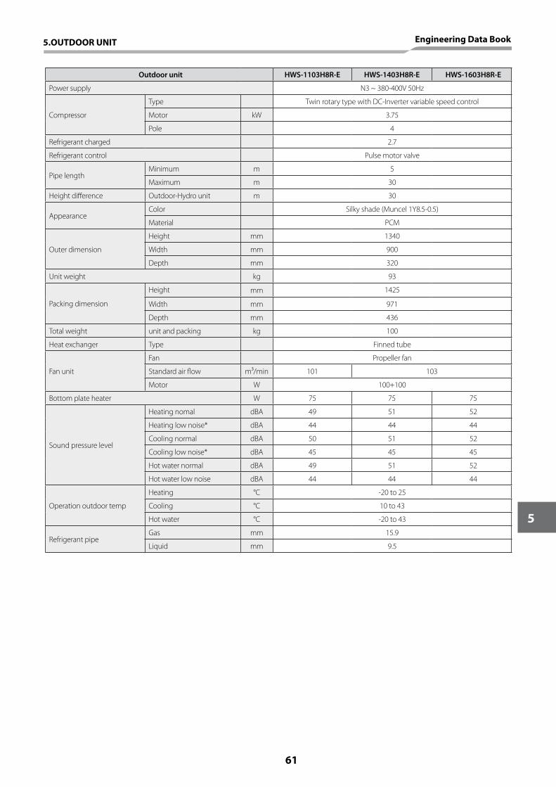
Outdoor unit HWS-1103H8R-E HWS-1403H8R-E HWS-1603H8R-E
Power supply N3 ~ 380-400V 50Hz
Compressor
Type Twin rotary type with DC-Inverter variable speed control
Motor kW 3.75
Pole 4
Refrigerant charged 2.7
Refrigerant control Pulse motor valve
Pipe lengthMinimum m 5
Maximum m 30
Height difference Outdoor-Hydro unit m 30
AppearanceColor Silky shade (Muncel 1Y8.5-0.5)
Material PCM
Outer dimension
Height mm 1340
Width mm 900
Depth mm 320
Unit weight kg 93
Packing dimension
Height mm 1425
Width mm 971
Depth mm 436
Total weight unit and packing kg 100
Heat exchanger Type Finned tube
Fan unit
Fan Propeller fan
Standard air flow m³/min 101 103
Motor W 100+100
Bottom plate heater W 75 75 75
Sound pressure level
Heating nomal dBA 49 51 52
Heating low noise* dBA 44 44 44
Cooling normal dBA 50 51 52
Cooling low noise* dBA 45 45 45
Hot water normal dBA 49 51 52
Hot water low noise dBA 44 44 44
Operation outdoor temp
Heating °C -20 to 25
Cooling °C 10 to 43
Hot water °C -20 to 43
Refrigerant pipeGas mm 15.9
Liquid mm 9.5
5.OUTDOOR UNIT Engineering Data Book
61
5
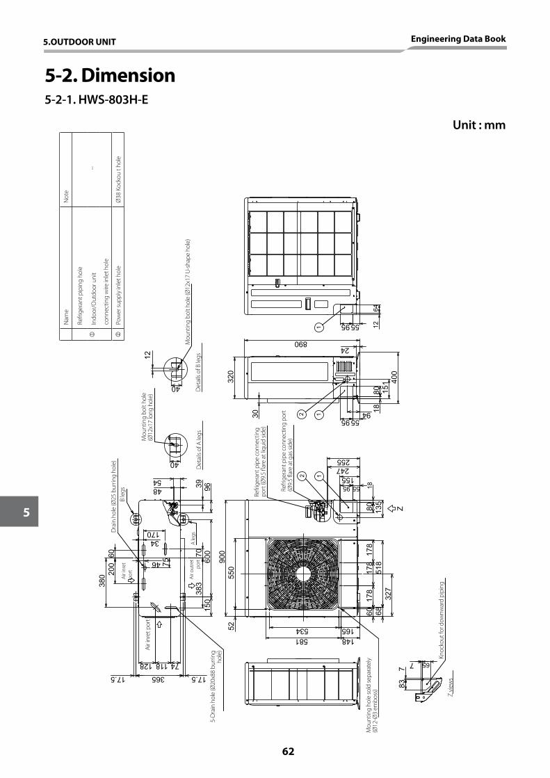
5-2. Dimension5-2-1. HWS-803H-E
900
135
534581
178
178
60 6851
817
8
327
7
837
65
148165
70
365
74
5255
0
150
17.5
600
383
34
118128
17.5
6038
0 200
46 75
170
890
6412
55
18
400
151
8018
80 Z
95 5594
255
95155
247
55
12
12
24
95
1
12
40
40
5448
30
320
9639
Dra
in h
ole
(Ø25
bur
ring
hole
)
Air i
nret
po
rt
Air o
utre
t po
rt
Air i
nret
por
t
5-D
rain
hol
e (Ø
20x8
8 bu
rring
ho
le)
B le
gs
A le
gs
Mou
ntin
g ho
le so
ld se
para
tely
(Ø
12-Ø
3 em
boss
)
Refri
gera
nt p
ipe
conn
ectin
g po
rt (Ø
9.5
flare
at l
iqui
d sid
e)
Refri
gera
nt p
ipe
conn
ectin
g po
rt
(Ø9.
5 fla
re a
t gas
side
)
Knoc
kout
for d
ownw
ard
pipi
ngZ
view
s
Mou
ntin
g bo
lt ho
le
(Ø12
x17
long
hol
e)
Det
ails
of A
legs
Det
ails
of B
legs
Mou
ntin
g bo
lt ho
le (Ø
12x1
7 U
-sha
pe h
ole)
Unit : mm
Nam
eN
ote
Refri
gera
nt p
ipin
g ho
le
--In
door
/Out
door
uni
t
conn
ectin
g w
ire in
let h
ole
Pow
er su
pply
inle
t hol
eØ
38 K
ocko
u t h
ole
5.OUTDOOR UNIT Engineering Data Book
62
5
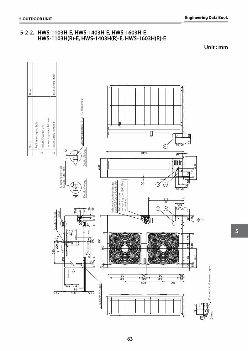
96394854
600
70
34
75
46
170
6038
020
017.5
128 11874
383
150
17.5365
40
65
83
Z
12
5595
1880 13
5
155
613605
900
7058174581
178
178
178
518
5255
0
360655
327
60 68
534 121 534 85
7 7
40
12
12
95 55 1264
1
1340
320
30
559594 18
80 151
400
24
Dra
in h
ole
(Ø25
)
Air i
nret
por
t
Air o
utre
t por
t
Air i
nret
por
t
5-D
rain
hol
e (Ø
20x8
8)
B le
gs
A le
gs
Refri
gera
nt p
ipe
conn
ectin
g po
rt (Ø
9.5
flare
at l
iqui
d sid
e)Re
frige
rant
pip
e co
nnec
ting
port
(Ø9.
5 fla
re
at g
as si
de)
Knoc
kout
for d
ownw
ard
pipi
ngZ
view
s
Mou
ntin
g bo
lt ho
le
(Ø12
x17
long
hol
e)
Det
ails
of A
legs
Det
ails
of B
legs
Mou
ntin
g bo
lt ho
le (Ø
12x1
7 U
-sha
pe h
ole)
Nam
eN
ote
Refri
gera
nt p
ipin
g ho
le
--In
door
/Out
door
uni
t
conn
ectin
g w
ire in
let h
ole
Pow
er su
pply
inle
t hol
eØ
38 K
ocko
u t h
ole
Unit : mm
5-2-2. HWS-1103H-E, HWS-1403H-E, HWS-1603H-E HWS-1103H(R)-E, HWS-1403H(R)-E, HWS-1603H(R)-E
5.OUTDOOR UNIT Engineering Data Book
63
5
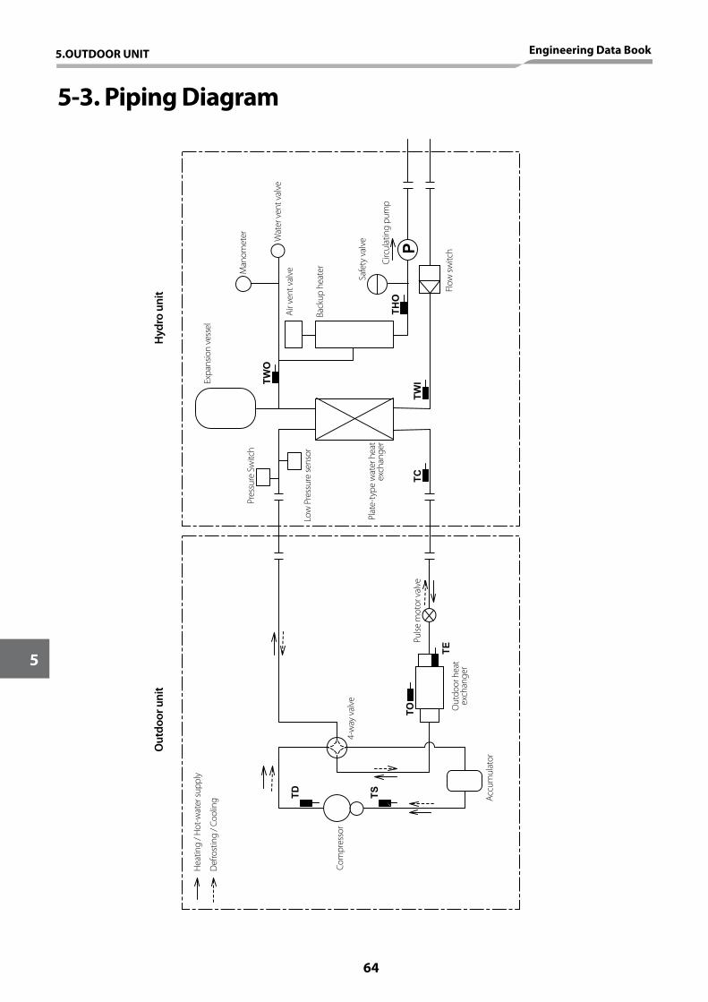
5-3. Piping Diagram
P
TWO
THO
TWI
TE
TO
TS
TD
TC
Hea
ting
/ Hot
-wat
er su
pply
Def
rost
ing
/ Coo
ling
Com
pres
sor
Accu
mul
ator
Out
door
hea
t ex
chan
ger
Pulse
mot
or v
alve
Plat
e-ty
pe w
ater
hea
t ex
chan
ger
Low
Pre
ssur
e se
nsor
Pres
sure
Sw
itch
Expa
nsio
n ve
ssel
Out
door
uni
tH
ydro
uni
t
Man
omet
er
Air v
ent v
alve
Back
up h
eate
r
Safe
ty v
alve
Circ
ulat
ing
pum
p
Flow
switc
h
4-w
ay v
alve
Wat
er v
ent v
alve
5.OUTDOOR UNIT Engineering Data Book
64
5
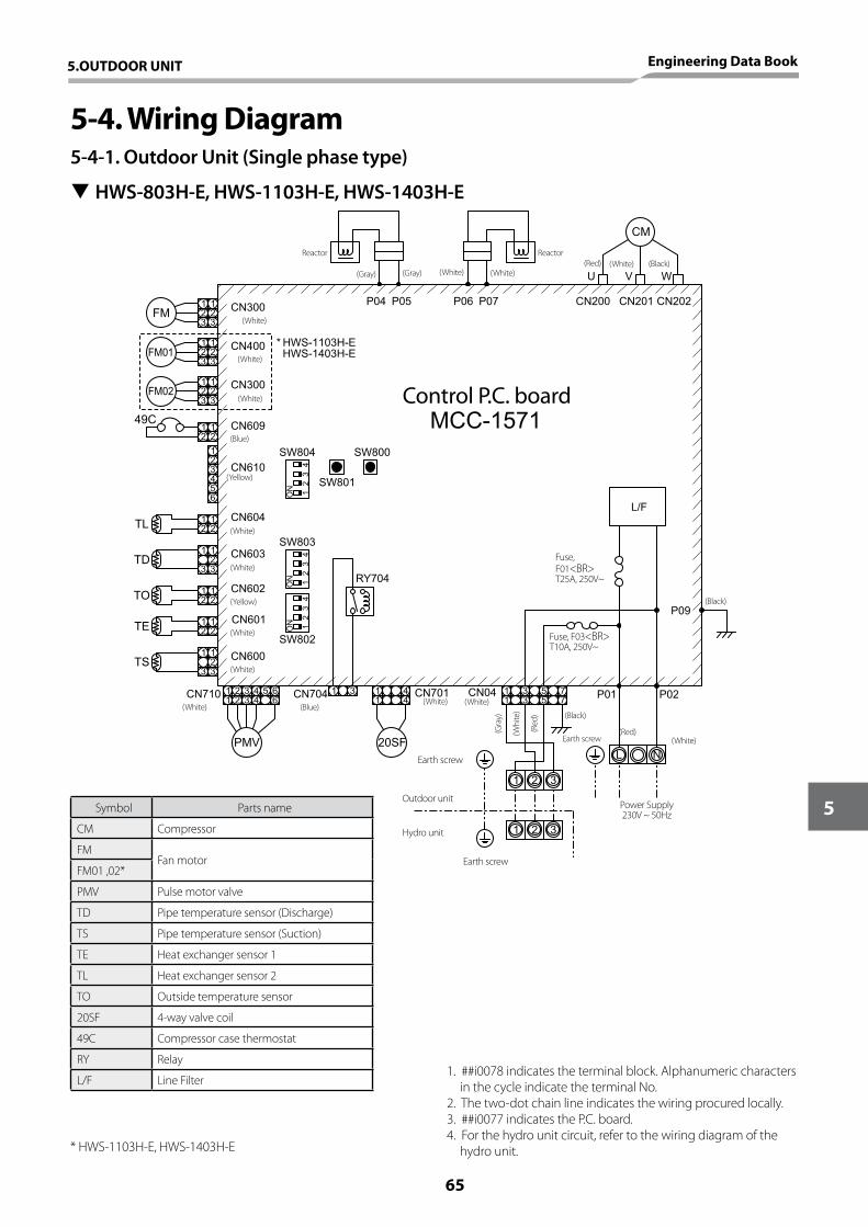
5-4. Wiring Diagram5-4-1. Outdoor Unit (Single phase type)
SW802
CN600
CN710 CN704 CN701
SW803
CN601
CN602
CN603
CN604
RY704
CN04
CN609
SW800CN610
SW804
SW801
CN300
* HWS-1103H-E HWS-1403H-E
CN202CN201CN200P07P06
L/F
MCC-1571
P04 P05
CM
U V W
123
123
FM
49C12
12
123456
TL
TD
TO
TE
TS
12
12
1 1233
12
12
12
12
1 1233
1 2 3 4 5 61 2 3 4 6
PMV
1 3 1 41 4
20SF
1 3 51 3 5
77 P01 P02
1 2 3
1 2 3
L N
P09
ON 1
23
4
ON 1
23
4
ON 1
23
4
CN400
CN300
123
123
FM01
FM02123
123
Reactor Reactor
(Gray) (Gray) (White) (White)(White) (Black)(Red)
(White)
(White)
(White)
(White)
(White)
(White)
(White)
(White)(White) (White)
(White)
Earth screw
Outdoor unit
Hydro unit
(Blue)
(Yellow)
(Yellow)
(Blue)
Earth screw
Earth screw
Power Supply230V ~ 50Hz
(Black)
(Red)(Whi
te)
(Gra
y)
(Red
)
(Black)
Fuse, F01<BR> T25A, 250V~
Fuse, F03<BR> T10A, 250V~
Control P.C. board
1. ##i0078 indicates the terminal block. Alphanumeric characters in the cycle indicate the terminal No.
2. The two-dot chain line indicates the wiring procured locally.3. ##i0077 indicates the P.C. board.4. For the hydro unit circuit, refer to the wiring diagram of the
hydro unit.
Symbol Parts name
CM Compressor
FMFan motor
FM01 ,02*
PMV Pulse motor valve
TD Pipe temperature sensor (Discharge)
TS Pipe temperature sensor (Suction)
TE Heat exchanger sensor 1
TL Heat exchanger sensor 2
TO Outside temperature sensor
20SF 4-way valve coil
49C Compressor case thermostat
RY Relay
L/F Line Filter
* HWS-1103H-E, HWS-1403H-E
T HWS-803H-E, HWS-1103H-E, HWS-1403H-E
5.OUTDOOR UNIT Engineering Data Book
65
5
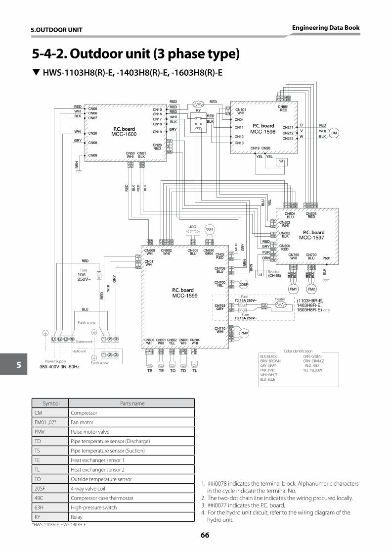
(1103H8R-E, 1403H8R-E, 1603H8R-E)
MCC-1597
MCC-1599
MCC-1596MCC-1600
10A 250V~
380-400V 3N~50Hz
1. ##i0078 indicates the terminal block. Alphanumeric characters in the cycle indicate the terminal No.
2. The two-dot chain line indicates the wiring procured locally.3. ##i0077 indicates the P.C. board.4. For the hydro unit circuit, refer to the wiring diagram of the
hydro unit.
Symbol Parts name
CM Compressor
FM01 ,02* Fan motor
PMV Pulse motor valve
TD Pipe temperature sensor (Discharge)
TS Pipe temperature sensor (Suction)
TE Heat exchanger sensor 1
TL Heat exchanger sensor 2
TO Outside temperature sensor
20SF 4-way valve coil
49C Compressor case thermostat
63H High-pressure switch
RY Relay
5-4-2. Outdoor unit (3 phase type)
Earth screw
Fuse
Earth screw
P.C. board
P.C. board
P.C. boardP.C. board
Fuse
Fuse
Heater
only
Reactor
BLK : BLACKBRW : BROWNGRY : GRAYPNK : PINKWHI : WHITEBLU : BLUE
GRN : GREENORN : ORANGEXRED : REDYEL : YELLOW
Color identification
Outdoor unit
Hydro unit
Power Supply
*HWS-1103H-E, HWS-1403H-E
T HWS-1103H8(R)-E, -1403H8(R)-E, -1603H8(R)-E
5.OUTDOOR UNIT Engineering Data Book
66
5
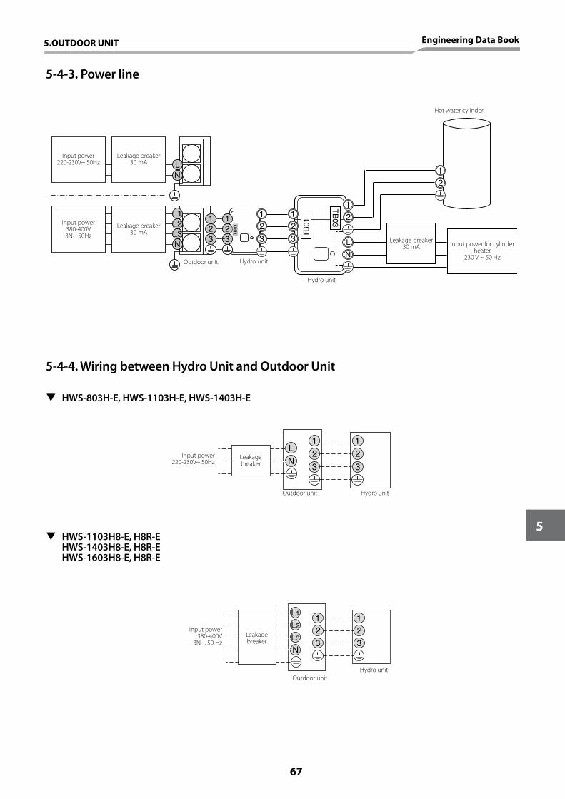
5-4-3. Power line
5-4-4. Wiring between Hydro Unit and Outdoor Unit
NL
N
1
32
1
32
L1L2L3 T
B01
12
3
12
3
12
12
L
N
TB
03
TB
01
1122
L
N33
Input power380-400V3N~ 50Hz
Leakage breaker 30 mA
Leakage breaker 30 mA
Outdoor unit Hydro unit
Hydro unit
Hot water cylinder
Leakage breaker 30 mA Input power for cylinder
heater230 V ~ 50 Hz
Input power220-230V~ 50Hz
Leakage breaker
Outdoor unit Hydro unit
T HWS-803H-E, HWS-1103H-E, HWS-1403H-E
T HWS-1103H8-E, H8R-E HWS-1403H8-E, H8R-E HWS-1603H8-E, H8R-E
Input power220-230V~ 50Hz
1122
L3
L2
L1
N33
Hydro unitOutdoor unit
Leakage breaker
Input power380-400V
3N~, 50 Hz
5.OUTDOOR UNIT Engineering Data Book
67
5
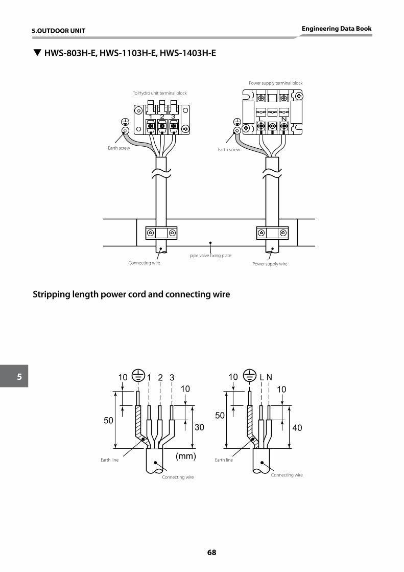
11
22L
N33 T
B01
L N1 2 3
(mm)
1010 L N
40
10
5050
10
30
1 2 3
11
22L
N33 T
B01
L N1 2 3
(mm)
1010 L N
40
10
5050
10
30
1 2 3
Stripping length power cord and connecting wire
T HWS-803H-E, HWS-1103H-E, HWS-1403H-E
1122
L
N33
1122
L
N33
To Hydro unit terminal block
Earth screw
Earth line
Connecting wire Connecting wire
Earth line
Connecting wire
pipe valve fixing plate
Power supply wire
Earth screw
Power supply terminal block
5.OUTDOOR UNIT Engineering Data Book
68
5
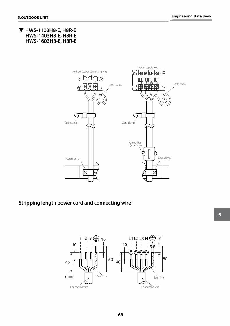
1 2 3 L1 L2 L3 N
50
10
(mm)
10
50
10
40
1 2 3
10
40
L1 L2 L3 N
T HWS-1103H8-E, H8R-EHWS-1403H8-E, H8R-EHWS-1603H8-E, H8R-E
Earth line
Connecting wire Connecting wire
Earth line
Hydro/outdoor connecting wirePower supply wire
Earth screwEarth screw
Cord clamp
Cord clamp Cord clamp
Clamp filter(accessory)
Cord clamp
Stripping length power cord and connecting wire
5.OUTDOOR UNIT Engineering Data Book
69
5
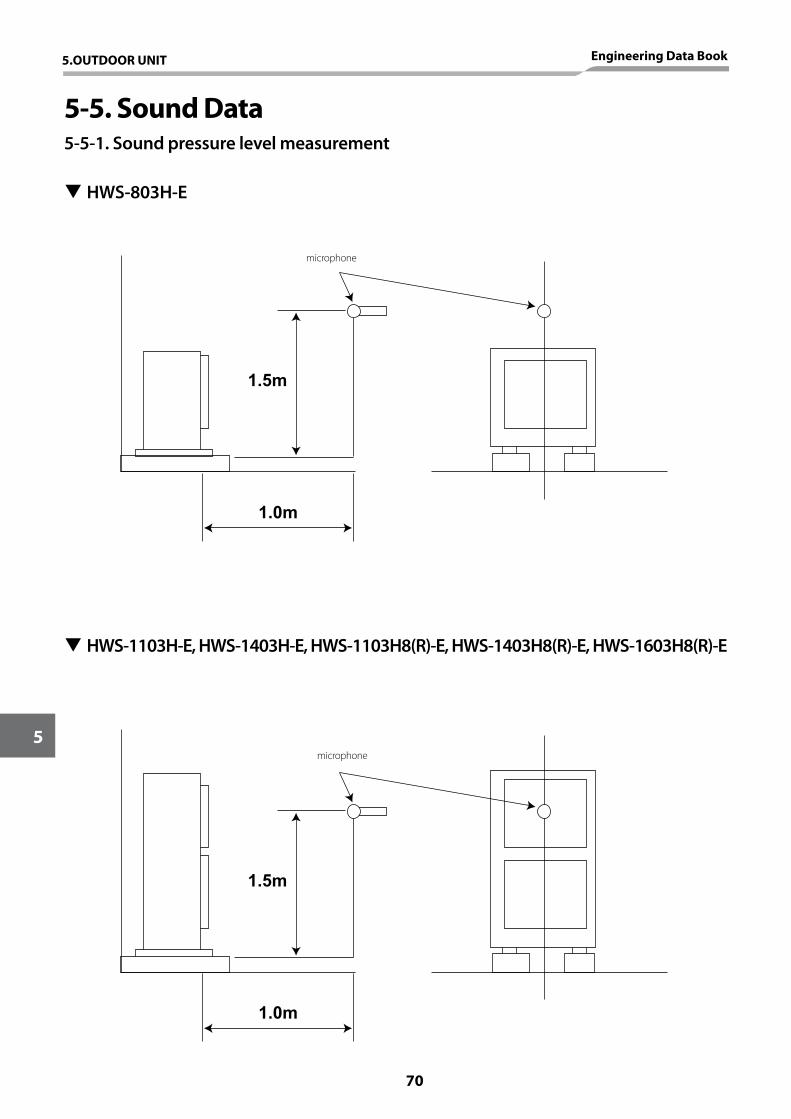
5-5. Sound Data5-5-1. Sound pressure level measurement
T HWS-803H-E
T HWS-1103H-E, HWS-1403H-E, HWS-1103H8(R)-E, HWS-1403H8(R)-E, HWS-1603H8(R)-E
1.5m
1.0m
1.5m
1.0m
microphone
microphone
5.OUTDOOR UNIT Engineering Data Book
70
5
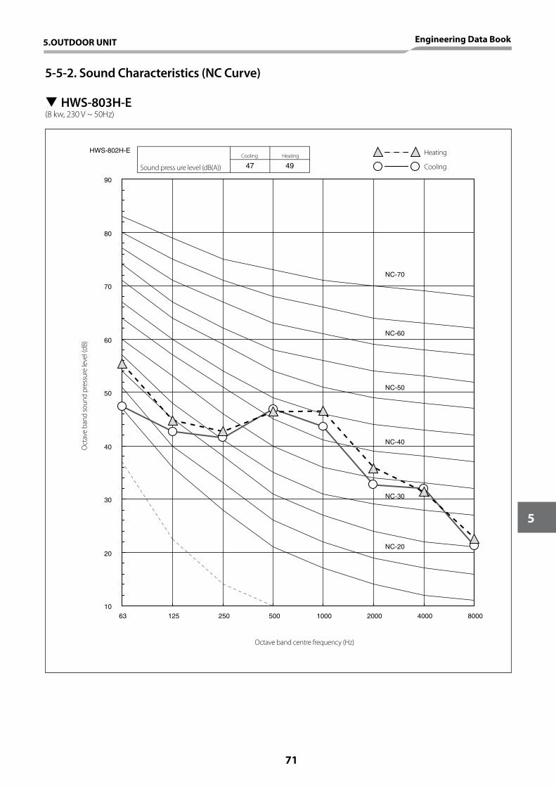
HWS-802H-E
10
20
30
40
50
60
70
80
90
63 125 250 500 1000 2000 4000 8000
NC-70
NC-60
NC-50
NC-40
NC-30
NC-20
47 49
5-5-2. Sound Characteristics (NC Curve)
T HWS-803H-E(8 kw, 230 V ~ 50Hz)
Octave band centre frequency (Hz)
Oct
ave
band
soun
d pr
essu
re le
vel (
dB)
Sound press ure level (dB(A))
Cooling Heating Heating
Cooling
5.OUTDOOR UNIT Engineering Data Book
71
5
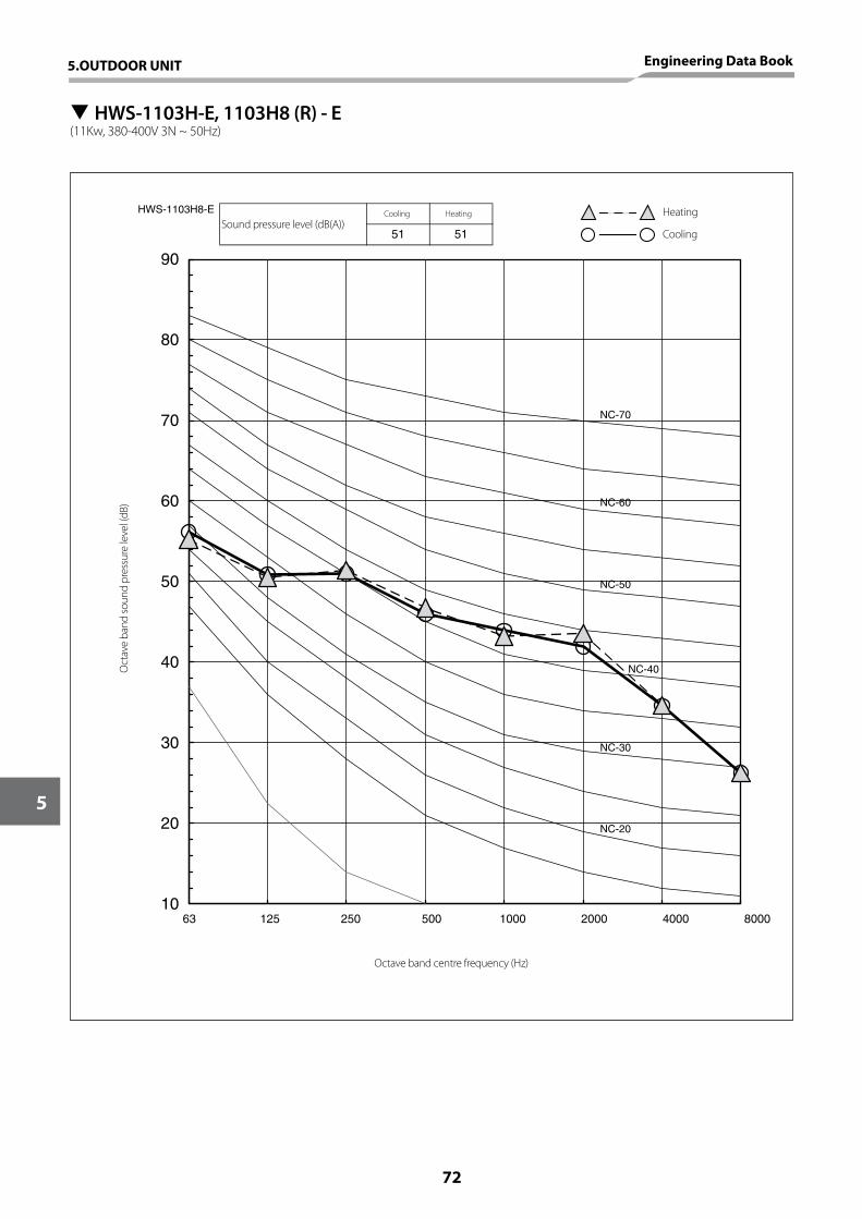
10
20
30
40
50
60
70
80
90
63 125 250 500 1000 2000 4000 8000
NC-70
NC-60
NC-50
NC-40
NC-30
NC-20
51 51
HWS-1103H8-E
T HWS-1103H-E, 1103H8 (R) - E(11Kw, 380-400V 3N ~ 50Hz)
Sound pressure level (dB(A))Cooling Heating Heating
Cooling
Octave band centre frequency (Hz)
Oct
ave
band
soun
d pr
essu
re le
vel (
dB)
5.OUTDOOR UNIT Engineering Data Book
72
5
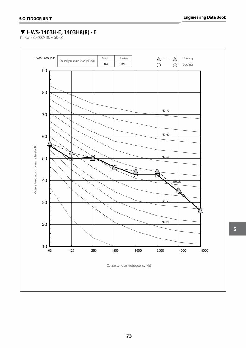
HWS-1403H8-E
10
20
30
40
50
60
70
80
90
63 125 250 500 1000 2000 4000 8000
NC-70
NC-60
NC-50
NC-40
NC-30
NC-20
53 54
T HWS-1403H-E, 1403H8(R) - E(14Kw, 380-400V 3N ~ 50Hz)
Sound pressure level (dB(A))Cooling Heating Heating
Cooling
Octave band centre frequency (Hz)
Oct
ave
band
soun
d pr
essu
re le
vel (
dB)
5.OUTDOOR UNIT Engineering Data Book
73
5
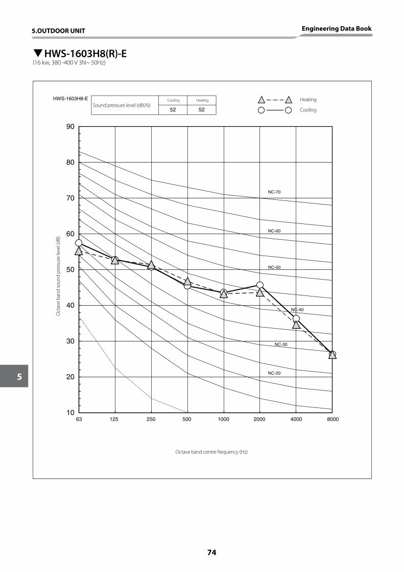
HWS-1603H8-E
10
20
30
40
50
60
70
80
90
63 125 250 500 1000 2000 4000 8000
NC-70
NC-60
NC-50
NC-40
NC-30
NC-20
52 52
THWS-1603H8(R)-E(16 kw, 380 -400 V 3N~ 50Hz)
Sound pressure level (dB(A))Cooling Heating Heating
Cooling
Octave band centre frequency (Hz)
Oct
ave
band
soun
d pr
essu
re le
vel (
dB)
5.OUTDOOR UNIT Engineering Data Book
74
5
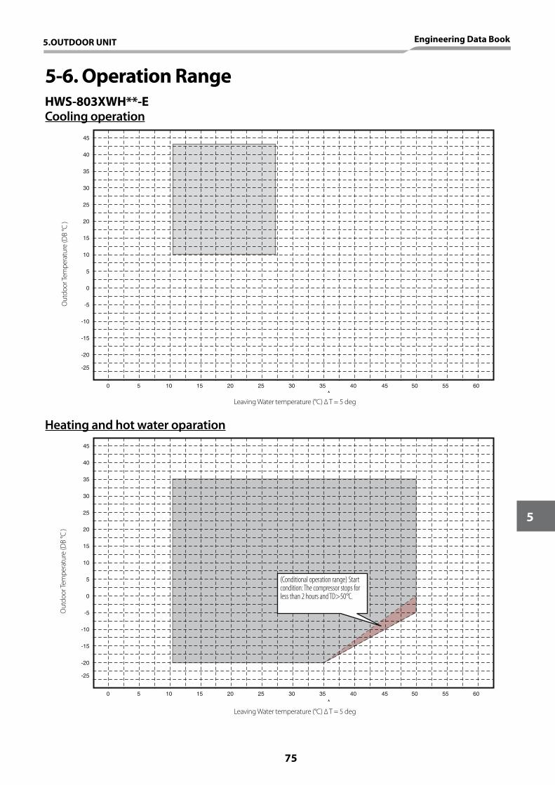
5-6. Operation Range
Heating and hot water oparation
Leaving Water temperature (°C) ∆ T = 5 deg
Leaving Water temperature (°C) ∆ T = 5 deg
Out
door
Tem
pera
ture
(DB
°C )
Out
door
Tem
pera
ture
(DB
°C )
-25
55 6040 45 50
-20
0 5 10 15 20 25 30 35
0
-5
-10
-15
45
40
35
30
25
20
15
10
5
-25
55 6040 45 50
-20
0 5 10 15 20 25 30 35
0
-5
-10
-15
45
40
35
30
25
20
15
10
5
-25
55 6040 45 50
-20
0 5 10 15 20 25 30 35
0
-5
-10
-15
45
40
35
30
25
20
15
10
5
-25
55 6040 45 50
-20
0 5 10 15 20 25 30 35
0
-5
-10
-15
45
40
35
30
25
20
15
10
5
Cooling operationHWS-803XWH**-E
(Conditional operation range) Start condition: The compressor stops for less than 2 hours and TD>50°C.
5.OUTDOOR UNIT Engineering Data Book
75
5
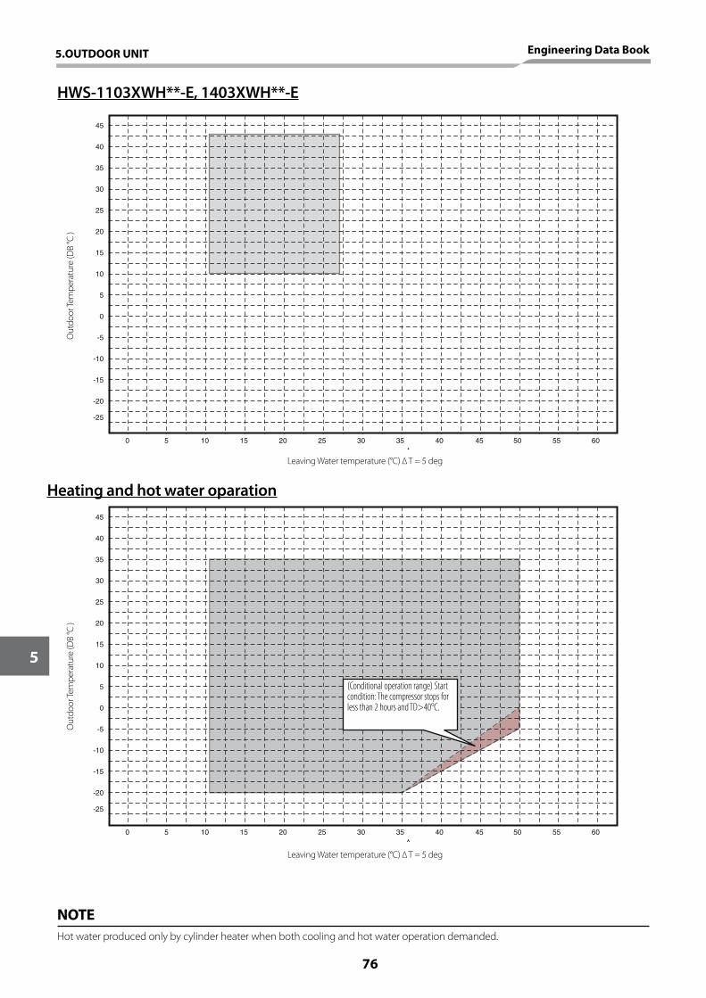
Heating and hot water oparation
Leaving Water temperature (°C) ∆ T = 5 deg
Leaving Water temperature (°C) ∆ T = 5 deg
Out
door
Tem
pera
ture
(DB
°C )
Out
door
Tem
pera
ture
(DB
°C )
HWS-1103XWH**-E, 1403XWH**-E
NOTEHot water produced only by cylinder heater when both cooling and hot water operation demanded.
-25
55 6040 45 50
-20
0 5 10 15 20 25 30 35
0
-5
-10
-15
45
40
35
30
25
20
15
10
5
-25
55 6040 45 50
-20
0 5 10 15 20 25 30 35
0
-5
-10
-15
45
40
35
30
25
20
15
10
5
-25
55 6040 45 50
-20
0 5 10 15 20 25 30 35
0
-5
-10
-15
45
40
35
30
25
20
15
10
5
-25
55 6040 45 50
-20
0 5 10 15 20 25 30 35
0
-5
-10
-15
45
40
35
30
25
20
15
10
5 (Conditional operation range) Start condition: The compressor stops for less than 2 hours and TD>40°C.
5.OUTDOOR UNIT Engineering Data Book
76
5

6. HOT WATER CYLINDER
77
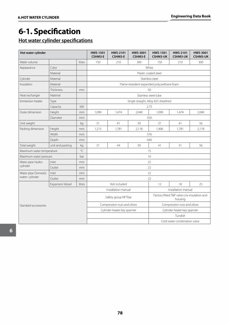
6-1. SpecificationHot water cylinder specifications
Hot water cylinder HWS-1501CSHM3-E
HWS-2101CSHM3-E
HWS-3001CSHM3-E
HWS-1501CSHM3-UK
HWS-2101CSHM3-UK
HWS-3001CSHM3-UK
Water volume litres 150 210 300 150 210 300
Appearance Color White
Material Plastic coated steel
Cylinder Material Stainless steel
Insulation Material Flame retardent expanded polyurethane foam
Thickness mm 50
Heat exchanger Material Stainless steel tube
Immersion heater Type Single straight, Alloy 825 sheathed
Capacity kW 2.75
Outer dimension Height mm 1,090 1,474 2,040 1,090 1,474 2,040
Diameter mm 550
Unit weight kg 31 41 59 31 41 56
Packing dimension Height mm 1,213 1,781 2,118 1,406 1,781 2,118
Width mm 576
Depth mm 640
Total weight unit and packing kg 37 44 59 41 51 56
Maximum water temperature °C 75
Maximum water pressure bar 10
Water pipe Hydro-cylinder
Inlet mm 22
Outlet mm 22
Water pipe Domestic water- cylinder
Inlet mm 22
Outlet mm 22
Expansion Vessel litres Not included 12 18 25
Standard accessories
Installation manual Installation manual
Safety group NF7bar Factory fitted T&P valve c/w insulation and housing
Compression nuts and olives Compression nuts and olives
Cylinder heater key spanner Cylinder heater key spanner
Tundish
Cold water combination valve
6.HOT WATER CYLINDER Engineering Data Book
78
6
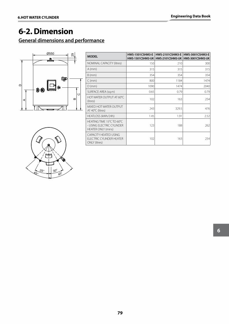
6-2. DimensionGeneral dimensions and performance
MODEL HWS-1501CSHM3-EHWS-1501CSHM3-UK
HWS-2101CSHM3-EHWS-2101CSHM3-UK
HWS-3001CSHM3-EHWS-3001CSHM3-UK
NOMINAL CAPACITY (litres) 150 210 300
A (mm) 315 315 315
B (mm) 354 354 354
C (mm) 800 1184 1474
D (mm) 1090 1474 2040
SURFACE AREA (sq.m) 0.65 0.79 0.79
HOT WATER OUTPUT AT 60°C (litres) 102 163 254
MIXED HOT WATER OUTPUT AT 40°C (litres) 243 329.5 476
HEATLOSS (kWh/24h) 1.45 1.91 2.52
HEATING TIME 15°C TO 60°C - USING ELECTRIC CYLINDER HEATER ONLY (mins)
123 188 262
CAPACITY HEATED USING ELECTRIC CYLINDER HEATER ONLY (litres)
102 163 254
CB
DA
Ø550
29
25° 30°45° 45°
6.HOT WATER CYLINDER Engineering Data Book
79
6
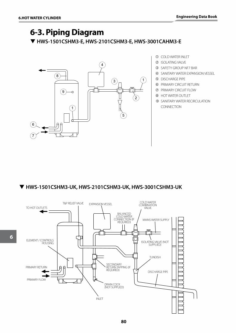
T HWS-1501CSHM3-UK, HWS-2101CSHM3-UK, HWS-3001CSHM3-UK
TO HOT OUTLETS
ELEMENT / CONTROLS HOUSING
PRIMARY RETURN
PRIMARY FLOW
T&P RELIEF VALVE EXPANSION VESSEL
BALANCED COLD WATER
CONNECTION (IF REQUIRED)
COLD WATER COMBINATION
VALVE
MAINS WATER SUPPLY
ISOLATING VALVE (NOT SUPPLIED)
TUNDISH
DISCHARGE PIPE
INLET
DRAIN COCK(NOT SUPPLIED)
SECONDARY RETURN TAPPING (IF REQUIRED)
6-3. Piping Diagram T HWS-1501CSHM3-E, HWS-2101CSHM3-E, HWS-3001CAHM3-E
1
4
3
2
5
6
8
9
7
1
COLD WATER INLET ISOLATING VALVE SAFETY GROUP NF7 BAR SANITARY WATER EXPANSION VESSEL DISCHARGE PIPE PRIMARY CIRCUIT RETURN PRIMARY CIRCUIT FLOW HOT WATER OUTLET
SANITARY WATER RECIRCULATION CONNECTION
6.HOT WATER CYLINDER Engineering Data Book
80
6
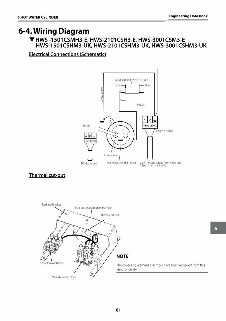
6-4. Wiring Diagram THWS -1501CSMH3-E, HWS-2101CSH3-E, HWS-3001CSM3-EHWS-1501CSHM3-UK, HWS-2101CSHM3-UK, HWS-3001CSHM3-UK
Electrical Connections (Schematic)
Thermal cut-out
1 2
A B
TBO6 (TTW)
TBO3 (230V)
Double pole thermal cut-out
Blue
Brown
Blue
BrownG
reen
/ Ye
llow
Sensor
TO Hydro unit
TTW sensor
Hot water cylinder heater 230V~ Mains supply from hidro unit.1.5mm2 min. cable size
Green / Yellow
Thermal cut-out
Reset button located on this faceTerminal bracket
Sensor terminal block
Mains terminal block
NOTE
The cover and element assembly have been removed from this view for clarity.
6.HOT WATER CYLINDER Engineering Data Book
81
6

82


Air to Water Heat Pump
Engineering Data Book
Sub
ject
to
mis
prin
ting.
E /
Est
ia /
01.
201
1