Toshiba 1800 laptop manual
12
Tough Enough for Today’s World FIELD REPLACEABLE UNIT DOCUMENTATION 1800 Series GENERAL INFORMATION TOSHIBA Tools Required for Proper Disassembly and Reassembly: 1. Phillips Screwdriver (Size 1) 2. 5mm Flat head Screwdriver 3. Case Separator 4. ESD Wrist Strap 5. ESD mats 6. Tweezers Before attempting any of the following procedures, make sure that the main battery and AC adaptor is not connected to the unit and the environment in which you are working on is protected from Electro-Static Discharge(ESD). Satellite TM
description
Toshiba 1800 laptop manual. Describes parts that are replaceable. Describes how to repair and replace parts inside the laptop with step by step approach with pictures for easy understanding.
Transcript of Toshiba 1800 laptop manual
Tough Enough for Today’s World
FIELD REPLACEABLE UNIT DOCUMENTATION
1800 Series
GENERAL INFORMATION
TOSHIBATough Enough for Today’s World
FIELD REPLACEABLE UNIT DOCUMENTATION
1800 Series
GENERAL INFORMATION
TOSHIBATough Enough for Today’s World
FIELD REPLACEABLE UNIT DOCUMENTATION
1800 Series
GENERAL INFORMATION
TOSHIBATough Enough for Today’s World
FIELD REPLACEABLE UNIT DOCUMENTATION
1800 Series
GENERAL INFORMATION
TOSHIBATough Enough for Today’s World
FIELD REPLACEABLE UNIT DOCUMENTATION
1800 Series
GENERAL INFORMATION
TOSHIBATough Enough for Today’s World
FIELD REPLACEABLE UNIT DOCUMENTATION
1800 Series
GENERAL INFORMATION
TOSHIBATough Enough for Today’s World
FIELD REPLACEABLE UNIT DOCUMENTATION
1800 Series
GENERAL INFORMATION
TOSHIBATough Enough for Today’s World
FIELD REPLACEABLE UNIT DOCUMENTATION
1800 Series
GENERAL INFORMATION
TOSHIBATough Enough for Today’s World
FIELD REPLACEABLE UNIT DOCUMENTATION
1800 Series
GENERAL INFORMATION
TOSHIBATough Enough for Today’s World
FIELD REPLACEABLE UNIT DOCUMENTATION
1800 Series
GENERAL INFORMATION
TOSHIBATough Enough for Today’s World
FIELD REPLACEABLE UNIT DOCUMENTATION
1800 Series
GENERAL INFORMATION
TOSHIBATough Enough for Today’s World
FIELD REPLACEABLE UNIT DOCUMENTATION
1800 Series
GENERAL INFORMATION
TOSHIBATough Enough for Today’s World
FIELD REPLACEABLE UNIT DOCUMENTATION
1800 Series
GENERAL INFORMATION
TOSHIBATough Enough for Today’s World
FIELD REPLACEABLE UNIT DOCUMENTATION
1800 Series
GENERAL INFORMATION
TOSHIBATough Enough for Today’s World
FIELD REPLACEABLE UNIT DOCUMENTATION
1800 Series
GENERAL INFORMATION
TOSHIBATough Enough for Today’s World
FIELD REPLACEABLE UNIT DOCUMENTATION
1800 Series
GENERAL INFORMATION
TOSHIBATough Enough for Today’s World
FIELD REPLACEABLE UNIT DOCUMENTATION
1800 Series
GENERAL INFORMATION
TOSHIBATough Enough for Today’s World
FIELD REPLACEABLE UNIT DOCUMENTATION
1800 Series
GENERAL INFORMATION
TOSHIBATough Enough for Today’s World
FIELD REPLACEABLE UNIT DOCUMENTATION
1800 Series
GENERAL INFORMATION
TOSHIBATough Enough for Today’s World
FIELD REPLACEABLE UNIT DOCUMENTATION
1800 Series
GENERAL INFORMATION
TOSHIBATough Enough for Today’s World
FIELD REPLACEABLE UNIT DOCUMENTATION
1800 Series
GENERAL INFORMATION
TOSHIBATough Enough for Today’s World
FIELD REPLACEABLE UNIT DOCUMENTATION
1800 Series
GENERAL INFORMATION
TOSHIBATough Enough for Today’s World
FIELD REPLACEABLE UNIT DOCUMENTATION
1800 Series
GENERAL INFORMATION
TOSHIBATough Enough for Today’s World
FIELD REPLACEABLE UNIT DOCUMENTATION
1800 Series
GENERAL INFORMATION
TOSHIBATough Enough for Today’s World
FIELD REPLACEABLE UNIT DOCUMENTATION
1800 Series
GENERAL INFORMATION
TOSHIBATough Enough for Today’s World
FIELD REPLACEABLE UNIT DOCUMENTATION
1800 Series
GENERAL INFORMATION
TOSHIBATough Enough for Today’s World
FIELD REPLACEABLE UNIT DOCUMENTATION
1800 Series
GENERAL INFORMATION
TOSHIBATough Enough for Today’s World
FIELD REPLACEABLE UNIT DOCUMENTATION
1800 Series
GENERAL INFORMATION
TOSHIBATough Enough for Today’s World
FIELD REPLACEABLE UNIT DOCUMENTATION
1800 Series
GENERAL INFORMATION
TOSHIBATough Enough for Today’s World
FIELD REPLACEABLE UNIT DOCUMENTATION
1800 Series
GENERAL INFORMATION
TOSHIBATough Enough for Today’s World
FIELD REPLACEABLE UNIT DOCUMENTATION
1800 Series
GENERAL INFORMATION
TOSHIBATough Enough for Today’s World
FIELD REPLACEABLE UNIT DOCUMENTATION
1800 Series
GENERAL INFORMATION
TOSHIBATough Enough for Today’s World
FIELD REPLACEABLE UNIT DOCUMENTATION
1800 Series
GENERAL INFORMATION
TOSHIBATough Enough for Today’s World
FIELD REPLACEABLE UNIT DOCUMENTATION
1800 Series
GENERAL INFORMATION
TOSHIBATough Enough for Today’s World
FIELD REPLACEABLE UNIT DOCUMENTATION
1800 Series
GENERAL INFORMATION
TOSHIBATough Enough for Today’s World
FIELD REPLACEABLE UNIT DOCUMENTATION
1800 Series
GENERAL INFORMATION
TOSHIBATough Enough for Today’s World
FIELD REPLACEABLE UNIT DOCUMENTATION
1800 Series
GENERAL INFORMATION
TOSHIBA
Tools Required for Proper
Disassembly and Reassembly:
1. Phillips Screwdriver (Size 1)
2. 5mm Flat head Screwdriver
3. Case Separator
4. ESD Wrist Strap
5. ESD mats
6. Tweezers
Before attempting any of the following procedures,make sure that the main battery and AC adaptor is not connected to the unit and the environment in
which you are working on is protected fromElectro-Static Discharge(ESD).
SatelliteTM

TOSHIBATough Enough for Today’s World
TABLE OF CONTENTS:
1. BATTERY PACK REMOVAL
2. OPTIONAL PC CARD REMOVAL
3. HDD REMOVAL
4. MEMORY MODULE REMOVAL
5. MINI PCI CARD REMOVAL
6. MODEM BOARD REMOVAL
7. KEYBOARD REMOVAL
8. IPS SWITCH REMOVAL
9. COOLING MODULE REMOVAL
10. CPU REMOVAL
11. DVD-ROM/CD-ROM DRIVE REMOVAL
12. TOP COVER REMOVAL
13. HDD/BATTERY BOARD REMOVAL
14. RTC BATTERY REMOVAL
15. VOLUME CONTROL BOARD REMOVAL
16. SPEAKERS REMOVAL
17. FDD REMOVAL
18. LED BOARD REMOVAL
19. SYSTEM BOARD REMOVAL
20. 13.3’ DISPLAY MASK REMOVAL
21. FL INVERTER AND 13.3’ LCD REMOVAL
22. 14’’ DISPLAY MASK REMOVAL
23. FL INVERTER AND 14’’ LCD REMOVAL
FIELD REPLACEABLE UNIT DOCUMENTATION
1800 Series Satellite
TM

BATTERY PACK REMOVAL OPTIONAL PC CARD REMOVAL
TOSHIBATough Enough for Today’s World
1. Turn the computer upside down as shown.2. Slide the battery release lever in the direction of the arrow. 3. Slide the battery pack to the right and lift it out.
HDD REMOVAL
3. Remove one M2.5x4 black flat head screw securing the HDD assembly.4 Grasp the HDD bracket handle and pull to disconnect the HDD assembly.5. Lift the HDD assembly out of the HDD bay.
1. Turn the computer upside down. 2. Remove one M2.5x4 black flat head screw securing HDD slot cover and pull out the cover.
.
NOTE: Before removing any PCCARD device, make sure it is “STOPPED” in the PC Card Manager.
FIELD REPLACEABLE UNIT DOCUMENTATION
1800 Series
Batteryrelease leverBattery pack
Eject buttonPC card lock
M2.5x4 blackflat head screwHDD slot cover
1. Slide the PC Card lock to unlock position2. Press the eject button to pop it out.3. Press the eject button and remove the PC card.
PC card
HDD bracket handle
HDD assembly
M2.5x4 black flat head screw
SatelliteTM
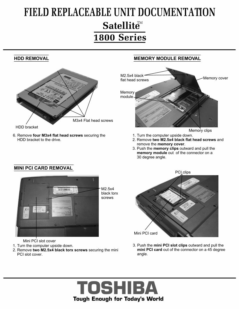
MEMORY MODULE REMOVAL
1. Turn the computer upside down. 2. Remove two M2.5x4 black flat head screws and remove the memory cover.3. Push the memory clips outward and pull the memory module out of the connector on a 30 degree angle.
TOSHIBATough Enough for Today’s World
MINI PCI CARD REMOVAL
FIELD REPLACEABLE UNIT DOCUMENTATION
1800 Series
1. Turn the computer upside down.2. Remove two M2.5x4 black torx screws securing the mini PCI slot cover.
3. Push the mini PCI slot clips outward and pull the mini PCI card out of the connector on a 45 degree angle.
HDD REMOVAL
M3x4 Flat head screws
HDD bracket
6. Remove four M3x4 flat head screws securing the HDD bracket to the drive.
Memory clips
Memorymodule
M2.5x4 blackflat head screws Memory cover
Mini PCI slot cover
M2.5x4 black torxscrews
Mini PCI card
PCI clips
SatelliteTM

MODEM REMOVAL
1. Remove one M2.5x4 black flat head screw securing the modem slot cover.2. Insert the case separator into the notched side of the cover and lift up to release the two latches securing the left side of the modem slot cover.
TOSHIBATough Enough for Today’s World
1. Open the display panel.2. Remove the Keyboard holder at the top of the keyboard.
3. Remove two M2.5x2.6 black screws securing the keyboard.
KEYBOARD REMOVAL
FIELD REPLACEABLE UNIT DOCUMENTATION
1800 Series
3. Remove the glass tape securing the RJ-11 jack cable.4. Remove two M2x4 brass screws securing the modem board.5. Lift up the modem board to disconnect it from the system board.6. Remove the RJ-11 jack from the modem board.
Modem slot cover M2.5x4 black flat head screw
M2x4 brass screws
Modem
RJ11 Jack
Latch
Keyboard holder M2.5x2.6 black screws
SatelliteTM

4. Lift out the keyboard and set it on the palm rest.5. Disconnect the keyboard cable from PJ333 on the system board and lift out the keyboard.
KEYBOARD REMOVAL
FIELD REPLACEABLE UNIT DOCUMENTATION
1800 Series
TOSHIBATough Enough for Today’s World
IPS SWITCH REMOVAL
IPS SWITCH REMOVAL COOLING MODULE REMOVAL
PJ333
Keyboardcable
Keyboard
1. Remove one M2.5x4 black flat head screw securing the IPS switch cover(touchpad) from the battery compartment.2. Remove the IPS switch(touchpad) cover from the palm rest.
3. Disconnect the IPS switch cable from PJ339 on the system board and lift out the membrane switch assembly.
IPS switch cover
1. Remove four M2.5x6 black flat head screws securing the heat sink plate.2. Lift out the heat sink plate.
Heat sink plateM2.5x6 black flat head screws
M2.5x4 black flat head screw
IPS switchcable
Membraneswitchassy
PJ339
SatelliteTM

FIELD REPLACEABLE UNIT DOCUMENTATION
1800 Series
TOSHIBATough Enough for Today’s World
COOLING MODULE REMOVAL
3. Remove four M2x16 brass screws securing the cooling module.4. Disconnect the fan cable from PJ770 from the system board and lift out the Fan module.
Fan cable
PJ770
M2x16 brass screws
Cooling module
5. Slide the CPU lock in the direction of the arrow.6. Insert a 5mm flat head screwdriver on the top side of the CPU socket and push the socket in the direction of the arrow and lift out the CPU.
CD-ROM/DVD ROM DRIVE REMOVAL
1. Remove two M2x5.5 silver screws securing the CD-ROM/ DVD ROM drive.2. Slide the CD/DVD-ROM drive to the right to disconnect it from PJ321 on the system board.
CD/DVD-ROM drivebracket
M2x2 silver screws
Brass washers
3. Remove two M2x2 silver screws and two brass washers securing the CD/DVD- ROM drive bracket.
CD/DVD-ROMdrive
M2x5.5 silver screws
CPUlock
CPU
Flat head screwdriver
Silicone grease
SatelliteTM
.
NOTE: When installing the CPU make sure that a silicone grease is applied before attaching the cooling module. Please refer to FSB-200112 for the complete procedures on how to apply the silicone grease.
CPU REMOVAL
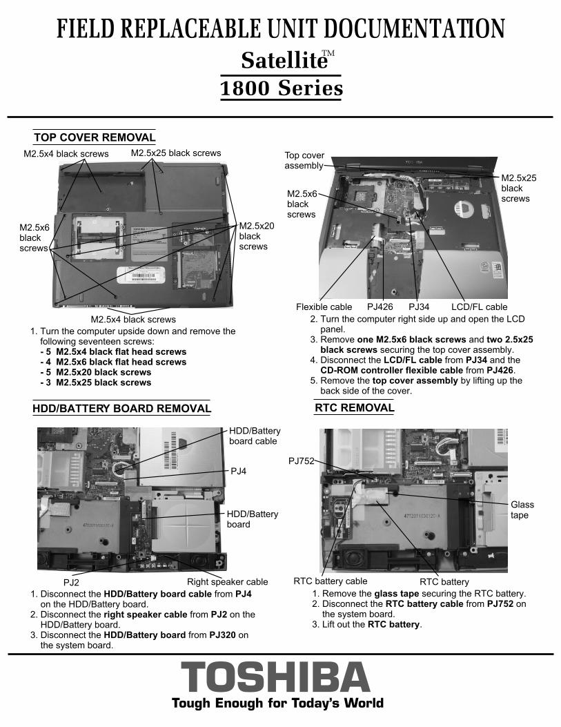
HDD/BATTERY BOARD REMOVAL
1. Disconnect the HDD/Battery board cable from PJ4 on the HDD/Battery board.2. Disconnect the right speaker cable from PJ2 on the HDD/Battery board.3. Disconnect the HDD/Battery board from PJ320 on the system board.
HDD/Batteryboard cable
HDD/Batteryboard
Right speaker cablePJ2
PJ4
RTC REMOVAL
1. Remove the glass tape securing the RTC battery.2. Disconnect the RTC battery cable from PJ752 on the system board.3. Lift out the RTC battery.
FIELD REPLACEABLE UNIT DOCUMENTATION
1800 Series
TOSHIBATough Enough for Today’s World
PJ752
RTC battery cable RTC battery
Glasstape
TOP COVER REMOVAL
1. Turn the computer upside down and remove the following seventeen screws: - 5 M2.5x4 black flat head screws - 4 M2.5x6 black flat head screws - 5 M2.5x20 black screws - 3 M2.5x25 black screws
2. Turn the computer right side up and open the LCD panel.3. Remove one M2.5x6 black screws and two 2.5x25 black screws securing the top cover assembly.4. Disconnect the LCD/FL cable from PJ34 and the CD-ROM controller flexible cable from PJ426.5. Remove the top cover assembly by lifting up the back side of the cover.
M2.5x6blackscrews
M2.5x4 black screws M2.5x25 black screws
M2.5x6blackscrews
M2.5x4 black screws
M2.5x20black screws
LCD/FL cablePJ34Flexible cable PJ426
M2.5x25blackscrews
Top cover assembly
SatelliteTM
TOSHIBATough Enough for Today’s World
FIELD REPLACEABLE UNIT DOCUMENTATION
1800 Series
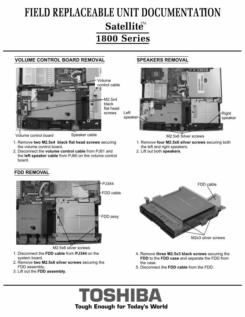
FDD REMOVAL
1. Disconnect the FDD cable from PJ344 on the system board.2. Remove two M2.5x6 silver screws securing the FDD assembly.3. Lift out the FDD assembly.
4. Remove three M2.5x3 black screws securing the FDD to the FDD case and separate the FDD from the case.5. Disconnect the FDD cable from the FDD.
FDD cable
PJ344
M2x3 silver screws
FDD cable
FDD assy
VOLUME CONTROL BOARD REMOVAL
1. Remove two M2.5x4 black flat head screws securing the volume control board.2. Disconnect the volume control cable from PJ61 and the left speaker cable from PJ60 on the volume control board.
SPEAKERS REMOVAL
1. Remove four M2.5x6 silver screws securing both the left and right speakers.2. Lift out both speakers.
Volume control board
M2.5x4 blackflat head screws
Volume control cable
Speaker cable M2.5x6 Silver screws
Right speaker
Left speaker
SatelliteTM
M2.5x6 silver screws
TOSHIBATough Enough for Today’s World
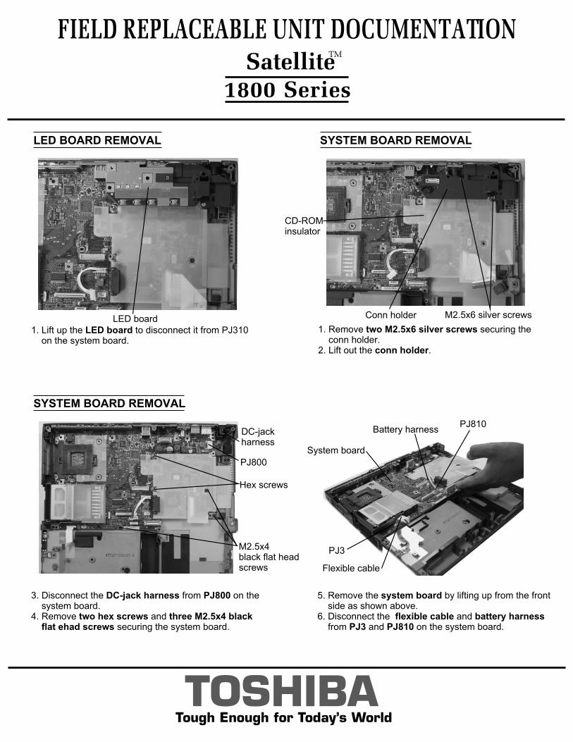
LED BOARD REMOVAL
FIELD REPLACEABLE UNIT DOCUMENTATION
1800 Series
SYSTEM BOARD REMOVAL
SYSTEM BOARD REMOVAL
3. Disconnect the DC-jack harness from PJ800 on the system board.4. Remove two hex screws and three M2.5x4 black flat ehad screws securing the system board.
5. Remove the system board by lifting up from the front side as shown above. 6. Disconnect the flexible cable and battery harness from PJ3 and PJ810 on the system board.
1. Lift up the LED board to disconnect it from PJ310 on the system board.
1. Remove two M2.5x6 silver screws securing the conn holder.2. Lift out the conn holder.
CD-ROMinsulator
M2.5x6 silver screwsConn holderLED board
M2.5x4black flat head screws
Hex screws
DC-jackharness
PJ800
System board
Battery harnessPJ810
PJ3
Flexible cable
SatelliteTM

1. Remove two mask seals at the bottom corners of the display assembly to expose two screws securing the display mask.2. Remove two M2.5x6 black screws securing the display mask.3. There are 23 latches securing the display mask. Carefully insert your fingers between the display mask and the LCD module and pry open the latches starting from the seven bottom latches, to the five latches on the right and left sides, ending with the six top latches.
FL INVERTER AND 13.3” LCD REMOVAL
1. Peel off the glass tape securing the FL cable.2. Remove one M2x5 brass screw securing FL inverter board.3. Carefully lift up the FL inverter board and disconnect the LCD/FL cable from CN1 and the FL cable from CN2.4. Remove four mask seals to expose four screws securing the left and right LCD brackets.5 Remove four M2X5 silver screws securing both brackets.6. Carefully rotate out the top of the LCD module enough to access the display cable.7. Peel off the tape securing the LCD/FL cable and disconnect the cable.8. Remove four M2x3 silver screws securing the left and right LCD brackets.
FIELD REPLACEABLE UNIT DOCUMENTATION Satellite
TM
1800 Series
TOSHIBATough Enough for Today’s World
13.3” DISPLAY MASK REMOVAL
LCD module
FL inverter boardLCD/FL cable
FL cable
M2x3silverscrews
M2x5 silver screws
M2x5 brassscrew
Latch
Mask seals
Displaymask
LCD
Glass tape
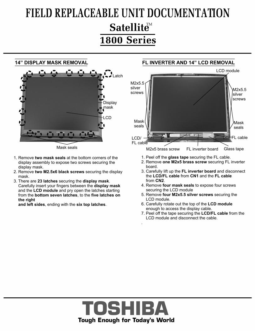
1. Remove two mask seals at the bottom corners of the display assembly to expose two screws securing the display mask.2. Remove two M2.5x6 black screws securing the display mask.3. There are 23 latches securing the display mask. Carefully insert your fingers between the display mask and the LCD module and pry open the latches starting from the bottom seven latches, to the five latches on the right and left sides, ending with the six top latches.
FL INVERTER AND 14” LCD REMOVAL
1. Peel off the glass tape securing the FL cable.2. Remove one M2x5 brass screw securing FL inverter board.3. Carefully lift up the FL inverter board and disconnect the LCD/FL cable from CN1 and the FL cable from CN2.4. Remove four mask seals to expose four screws securing the LCD module5. Remove four M2x5.5 silver screws securing the LCD module.6. Carefully rotate out the top of the LCD module enough to access the display cable.7. Peel off the tape securing the LCD/FL cable from the LCD module and disconnect the cable..
FIELD REPLACEABLE UNIT DOCUMENTATION Satellite
TM
1800 Series
TOSHIBATough Enough for Today’s World
14” DISPLAY MASK REMOVAL
Latch
Mask seals
Displaymask
LCD
LCD module
M2x5 brass screw FL inverter board
LCD/FL cable
FL cable
M2x5.5 silver screws
Glass tape
Mask seals
Mask seals
M2x5.5silverscrews