TOS7200 - KIKUSUITOS7200 /TOS7210S 3 1 Remote Control Overview This chapter describes device...
36
No. IB028953 Jul. 2018 DANGER This product generates high voltage! • Improper operation can lead to serious accidents. • To prevent accidents, be sure to read the section “Safety Precautions during Testing” in the user’s manual. TOS7200 Communication Interface Manual Insulation ResistanceTester TOS7210S(SPEC80776) PID Insulation Tester 1. Remote Control Overview 3 Connecting a cable 3 Protocol 4 Send and receive via the RS232C 4 Switching to local mode 5 2. Messages and Terminator Program message 6 Acknowledge message 7 Terminator 7 3. Device Messages Register-Related and General Purpose Messages 9 Test-Related Messages 14 System-Related Messages 20 Memory-Related Messages 23 4. Registers Structure of Status Data 26 5. List of Device Messages List of Register-Related and General Purpose Device Messages 29 List of Device Messages Relating to Tests 30 List of System-Related Device Messages 31 List of Memory-Related Device Messages 32 Index 33
Transcript of TOS7200 - KIKUSUITOS7200 /TOS7210S 3 1 Remote Control Overview This chapter describes device...

No. IB028953Jul. 2018
DANGERThis product generates high voltage!• Improper operation can lead to serious accidents.• To prevent accidents, be sure to read the section “Safety Precautions during Testing” in the user’s manual.
TOS7200
CommunicationInterface Manual
Insulation ResistanceTester
TOS7210S(SPEC80776)
PID Insulation Tester
1. Remote ControlOverview 3
Connecting a cable 3Protocol 4
Send and receive via the RS232C 4Switching to local mode 5
2. Messages and TerminatorProgram message 6
Acknowledge message 7Terminator 7
3. Device MessagesRegister-Related and General Purpose
Messages 9Test-Related Messages 14
System-Related Messages 20Memory-Related Messages 23
4. RegistersStructure of Status Data 26
5. List of Device MessagesList of Register-Related and General Purpose
Device Messages 29List of Device Messages Relating to Tests 30List of System-Related Device Messages 31
List of Memory-Related Device Messages 32
Index 33

2 TOS7200 /TOS7210S
There are five TOS7200/ 7210S Manuals listed as follows.
• Setup GuideSetup Guide is intended for first-time users of this product. Itprovides an overview of the product and notes on usage. It alsoexplains how to set up the product for testing the DUT. Alwaysread this manual before using the product.
• Quick ReferenceQuick Reference explains Panel description and operationbriefly.
• Safety InformationSafety information contains general safety precautions for thisproduct. Keep them in mind and make sure to observe them.
• User’s ManualUser’s manual is intended for first-time users of this product. Itprovides an overview of the product and notes on usage. It alsoexplains how to configure the product, operate the product,perform maintenance on the product, and so on.
• Communication Interface Manual (This manual)Interface Manual contains details about remote control. Themanual is provided on the accompanying CD-ROM.Interface manual is written for readers with sufficient basicknowledge of how to control instruments using a personalcomputer.
TOS7200/ TOS7210S Manuals are intended for users of the PIDInsulationTester and their instructors. Explanations are givenunder the presumption that the reader has knowledge about theelectrical aspects of electrical safety testing.
Before reading this manual
First read the User’s Manual, which includes information on theproduct’s hardware, to avoid connecting or operating the productincorrectly.
Product firmware versions
This manual applies to products with ROM versions 1.0X.
For information on how to check the product’s firmware version,see the user’s manual.
Copyrights
The contents of this manual may not be reproduced, in whole or inpart, without the prior consent of the copyright holder.
The specifications of this product and the contents of this manualare subject to change without prior notice.
©2014 Kikusui Electronics Corporation
• Device under test is also referred to as DUT.
• The term “PC” is used to refer generally to both personalcomputers and workstations.
• The following markings are used in the explanations in the text.
Indicates a potentially hazardous situation which, if ig-nored,could result in death or serious injury.
Indicates a potentially hazardous situation which, if ignored,may result in damage to the product or other property.
Indicates information that you should know.
Explanation of terminology or operation principle.
About the Operation Manuals Notations Used in This Manual
WARNING
CAUTION
DESCRIPTION

TOS7200 /TOS7210S 3
1 Remote Control
Overview
This chapter describes device messages and preparations for remotely controlling theTOS7200/ TOS7210S via the RS232C interface. Remote control can be used in anautomated system to set various functions, acquire measured data, and so on.
Connecting a cable
1 Turn off the POWER switch on the tester and the POWER switch on thecontroller.
2 Connect an RS232C cross-cable to the 9-pin RS232C connector on therear panel of the tester.The pin configuration of the connector is as shown below.
WARNING The remote control uses an external signal to turn ON/OFF the high voltage, which may result in great danger in some cases. Therefore, thorough safety measures must be taken to ensure that high voltage is not generated accidentally and that no one touches the DUT, high-voltage test leadwire, high-voltage probe, output terminals, or the like while high voltage is being generated. If such measures cannot be taken, do not perform remote control.
Performing remote control through the RS232C interface causes the REMOTE LED to light up, notifying the operator that no input other than the STOP switch and the STOP signal of the SIGNAL I/O is accepted. To restore local control, press the LOCAL key.
9-pin AT-type Connector
1: CD (carrier detection) 2: RXD (received data)
3: TXD (transmission data) 4: DTR (data terminal ready)
5: GND (signal ground)
6: DSR (data set ready) 7: RTS (request to send)
8: CTS (clear to send) 9: RI (ring indicator)
Tester side
123456789
123456789
D-SUB 9-pin female
D-SUB 9-pinfemale
Example of cross cable

4 TOS7200 /TOS7210S
Remote Control
Protocol
The RS232C protocol allows only the communication rate to be selected. Other items arefixed.
RS232C Protocol
Setting the communication rate
The communication rate is set after entering system setting. For details, see “SystemSettings”of chapter 4 "Basic Operation" on the user's manual.
1 With the SHIFT key held down, press the VOLT key to enter systemmode.This causes the leftmost digit (digit indicated as DOUBLE ACTION) of thevoltmeter to blink, indicating that the cursor is positioned at this digit.
2 Press the or key to move the cursor to the SPEED position.
3 With the SHIFT key held down, press the or key to change thecommunication rate.The communication rate can be selected from among 0: 9 600 bps; 1: 19 200bps; and 2: 38 400 bps.
4 Press the STOP switch to exit system setting.
Send and receive via the RS232C
Sending and receiving via the RS232C interface should be controlled by flow control orthe use of acknowledge messages. One-way transmission may fail to send and receivedata properly. For details, see “Acknowledge message” (p.7).”
RS232C flow control
Performing Xon/Xoff control allows sending and receiving of the tester to becontrolled. These control codes are executed by DC (device control) codes.
The DC code is as shown below.
Item Set value
Communication rate 9600/19200/38400 bps
Data length 8 bits
Parity bit None
Stop bit 2 bits
Code Function ASCII code
DC1 Request to send 11h
DC3 Request to stop sending 13h

TOS7200 /TOS7210S 5
Remote Control
Switching to local mode
When the TOS7200/TOS7210S is being controlled remotely via RS232C, press LOCAL keyon the front panel to return to local mode.
Transmission Control between the RS232C Terminal and Tester
DC3RXD DC1
TXD
The tester temporarily stops transmissionwithin three characters after receiving a DC3.
Up to threecharacters
Stop temporarily Resume transmission
DC3TXD
RXD
The RS-232C terminal must temporarily stop transmissionwithin 10 characters after receiving a DC3.
Up to 10characters
Stop temporarilyDC1
Resume transmission
Control of transmission from the RS-232C terminal to the power-supply controller
Control of transmission from the power-supply controller to the RS-232C terminal

6 TOS7200 /TOS7210S
2 Messages and Terminator
This section specifies the designations and descriptions used in this manual forcommunications between a controller(PC) and the tester (device).
Commands sent from the controller to the tester are designated as program messages.Responses sent from the tester to the controller are designated as response messages.
Each message consists of the program header section and data section.
Program message
Program messages are further divided into a command message and a query message.
A command message executes a specific function of the tester or modifies settings.
A query message inquires of the setting or status of the tester.
Writing a program message
A space (ASCII: 20h) is required between the program header section and datasection.
If there are multiple pieces of data, use commas (,) (ASCII: 2Ch) to link them.
Commandprogramheader
Queryprogramheader
Programheader
Responseprogramheader
Responsedata
Programdata
Data
Program messageCommand message
Query message
Programmessageterminator
Responsemessageterminator
Response message
Controller
Controller
Device
Device
Messages and Terminator
Program header Space (ASCII: 20h) Data
Program header Space (ASCII: 20h) Data
,

TOS7200 /TOS7210S 7
Messages and Terminator
The concatenation of program messages is performed using a semicolon (;) (ASCII:3Bh).
Acknowledge message
An acknowledge message is information sent from the tester to the controller. Itinforms the controller of the completion of processing of a program message.
The acknowledge message is an ASCII-codye character string consisting of the headeronly. It can be of either of the following two types:
・OK: Normal end
・ERROR: Occurrence of an abnormality such as a syntax error, etc.
The SILENT command message can be used to set whether an acknowledge messageis to be returned.
Terminator
A terminator indicating the end of a program message is designated as a programmessage terminator. A terminator indicating the end of a response message isdesignated as a response message terminator.
• Program message terminator
Either of the following two program message terminators may be used. This does notneed to be preset.
CR、CR+LF
• Response message terminator
Fixed to CR+LF
Program message
;
When writing data using hexadecimal numbers, append “#H” to each piece of data.Example: To write decimal number 10 in hexadecimal numbers, write “#H0A.
Acknowledge header

8 TOS7200 /TOS7210S
3 Device Messages
The program messages and response messages supported by this tester are designatedas device messages.
This section describes each device message supported by the tester.
An item enclosed in parentheses next to a device message indicates the abbreviation ofthat device message.
Special symbols and characters
The special symbols and characters used in this manual to describe a program messageor response message are defined as shown in the table below.
Symbol and character
Description
< >These brackets indicate program data.Do not use them in actual programs.
{ }Characters or numbers enclosed in these brackets and separated by “|” indicate that one in brackets should be selected. In actual programs, do not use the brackets.
_ This character indicates a space.

TOS7200 /TOS7210S 9
Register-Related and General Purpose Messages
Register-Related and General Purpose Messages
This subsection describes the device messages used to set, reset, or inquire about eachregister, and the general purpose device messages used to specify a terminator or otherelement.
*CLSResets the status byte register, event status register, device status register, fail register,invalid setting register, and error register (p.26).
Program message
• SyntaxComand message: *CLS
*ESRInquires about the contents of the event status register (p.27). The event status register isreset when it is read by the *ESR? message.
Program message
• SyntaxQuery message: *ESR?
Response messageReturns the contents of the event status register in response to *ESR? and resets theregister.
(Example) When bit 5 of the event status register has been set, 32 is returned.
*IDNInquires about the model number and firmware version of the tester.
Program message
• SyntaxQuery message: *IDN?
Response messageReturns the model number of the tester as shown in the following example, in responseto *IDN?.
The model number is “7210S” for the TOS7210S.
KIKUSUI ELECTRONICS CORP.,TOS7200,0,X.XX
Company name ModelNumber
Version number
Not used
Comma separator
10 TOS7200 /TOS7210S
Register-Related and General Purpose Messages
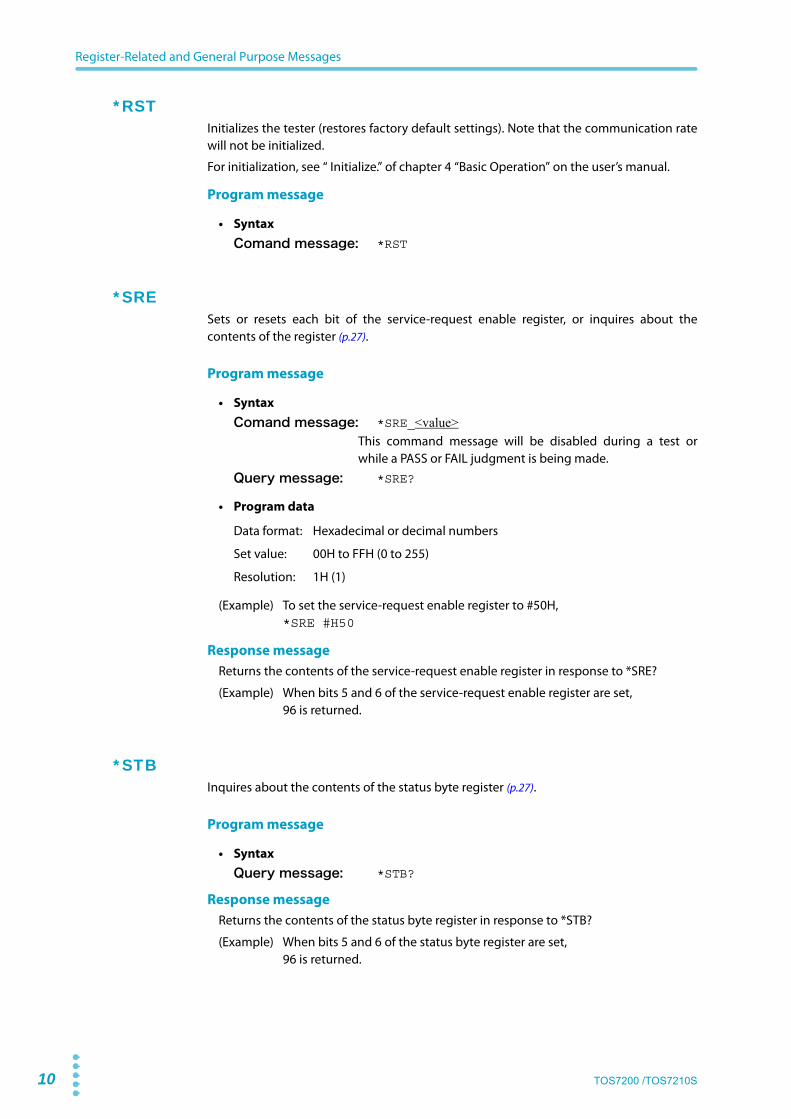
*RSTInitializes the tester (restores factory default settings). Note that the communication ratewill not be initialized.
For initialization, see “ Initialize.” of chapter 4 “Basic Operation” on the user’s manual.
Program message
• SyntaxComand message: *RST
*SRESets or resets each bit of the service-request enable register, or inquires about thecontents of the register (p.27).
Program message
• SyntaxComand message: *SRE_<value>
This command message will be disabled during a test orwhile a PASS or FAIL judgment is being made.
Query message: *SRE?
• Program data
Data format: Hexadecimal or decimal numbers
Set value: 00H to FFH (0 to 255)
Resolution: 1H (1)
(Example) To set the service-request enable register to #50H,*SRE #H50
Response messageReturns the contents of the service-request enable register in response to *SRE?
(Example) When bits 5 and 6 of the service-request enable register are set,96 is returned.
*STBInquires about the contents of the status byte register (p.27).
Program message
• SyntaxQuery message: *STB?
Response messageReturns the contents of the status byte register in response to *STB?
(Example) When bits 5 and 6 of the status byte register are set,96 is returned.

TOS7200 /TOS7210S 11
Register-Related and General Purpose Messages
CLRResets all registers (not including the enable register) to set the STOP flag.
This device message is also used to perform the same processing as DCL from the RS232Cinterface.
Program message
• SyntaxComand message: CLR
DSESets or resets each bit of the device-status enable register (p.27). Also inquires about thecontents of that register.
Program message
• SyntaxComand message: DSE_<value>
This command message will be disabled during a test or while a PASS or FAILjudgment is being made.Query message: DSE?
• Program data
Data format: Hexadecimal or decimal numbers
Set value: 00H to FFH (0 to 255)
Resolution: 1H (1)
(Example) To set the device-status enable register to 01H,DSE #H01
Response messageReturns the contents of the device-status enable register in response to DSE?
(Example) When bit 5 of the device-status enable register is set,32 is returned.
DSRInquires about the contents of the device status register (p.27).
Program message
• SyntaxQuery message: DSR?
Response messageReturns the contents of the device status register in response to DSR?
(Example) When bit 5 of the device status register is set,32 is returned.

12 TOS7200 /TOS7210S
Register-Related and General Purpose Messages
ERRInquires about the contents of the error register (p.28).
The error register will be reset when read by the ERR? message.
Program message
• SyntaxQuery message: ERR?
Response messageReturns the contents of the error register in response to ERR?, and resets the register.
(Example) When bit 3 of the error register is set,8 is returned.
FAILInquires about the contents of the fail register (p.28).
Program message
• SyntaxQuery message: FAIL?
Response messageReturns the contents of the fail register in response to FAIL?
(Example) When bit 4 of the fail register is set,16 is returned.
INVALID (INV)
Inquires about the contents of the invalid register (p.28).
Program message
• SyntaxQuery message: INVALID?
INV?
Response messageReturns the contents of the invalid register in response to INV?
(Example) When bit 3 of the invalid register is set,8 is returned.

TOS7200 /TOS7210S 13
Register-Related and General Purpose Messages
SILENT (SIL)
Sets whether an acknowledge message is returned in response to a message delimitedby the response-message terminator. Also inquires about the set value indicatingwhether an acknowledge message is returned by the SILENT? message.
The acknowledge message returns either “OK” or “ERROR.” To receive the acknowledgemessage, the RS232C setting should be full duplex communications.
Program message
• SyntaxComand message: SILENT_<{0|1}>
SIL_<{0|1}>
Query message: SILENT?SIL?
• Program data
Data format: Integer
Set value: 0: Returns an acknowledge message.1: Does not return an acknowledge message.
(Example) To makes a setting such that no acknowledge message is returned,SIL 1
Response messageReturns the set value of the acknowledge message in response to SIL?
(Example) When the current setting is “Does not to return the acknowledge message”,1 is returned.
STARTStarts a test.
Program message
• SyntaxComand message: START
This command message will be disabled during a test orwhile a PASS or FAIL judgment is being made.
STOPStops a test, or cancels a FAIL judgment, a PASS judgment, or the PASS HOLD status.
Program message
• SyntaxComand message: STOP
Full duplex communications: A communications system capable of always flowing data in both directions in data transmission between two parties. For setting of full duplex communications, see the operating manual of the PC.

14 TOS7200 /TOS7210S
Test-Related Messages
Test-Related Messages
This subsection describes the device messages used to set the test conditions or to check settings.
AUTORANGE (AUTOR)
Sets ON/OFF for auto-range or inquires about the current auto-range setting.
Program message
• SyntaxComand message: AUTORANGE_<{ON|OFF|1|0}>
AUTOR_<{ON|OFF|1|0}>
This command message will be disabled during a test orwhile a PASS or FAIL judgment is being made.
Query message: AUTORANGE?AUTOR?
• Program data
Data format: Character (integer)
Set value: OFF (0): Auto-range OFF (The fixed range applies.)ON (1) : Auto-range ON
(Example) To make settings so that measurement is made in auto-range,AUTOR ON
Response messageReturns the current setting in response to AUTOR?
(Example) When the current setting is auto-range,1 is returned.
LOWER (LOW)
Sets the lower resistance (LOWER) and ON/OFF for lower judgment. Also inquires aboutthe current lower resistance and the setting for lower judgment.
Program message
• SyntaxComand message: LOWER_<lower resistance,{ON|OFF|1|0}>
LOW_<lower resistance,{ON|OFF|1|0}>This command message will be disabled during a test orwhile a PASS or FAIL judgment is being made.
Query message: LOWER?LOW?
• Program data <lower resistance>
FAIL judgments are not made when the lower judgment and upper judgment functions are set to OFF. In this situation, if the timer is set to ON, a PASS judgment will be made, so you need to be careful.

TOS7200 /TOS7210S 15
Test-Related Messages
Data format: Real number
Set value: 0.01E6 to 5 000E6
Resolution: 0.01E6 (0.01E6 to 9.99E6)0.1E6 (10.0E6 to 99.9E6)1E6 (100E6 to 5 000E6)
unit: Ω
• Program data <{ON|OFF|1|0}>
Data format: Character (integer)
Set value: OFF (0): Lower judgment OFFON (1) : Lower judgment ON
(Example) To set the lower resistance to 999 MW,LOW 999E6,1
Response messageReturns the current lower resistance and ON/OFF for the lower judgment in response to LOW?
(Example) When the current lower resistance is 100 MΩ and the lower judgment isOFF,100E6,0 is returned.
MON Inquires about the current monitored values.
Program message
• SyntaxQuery message: MON?
Response messageReturns the current monitored values in the form of “monitored voltage, monitoredresistance, monitored current (TOS7210S only), elapsed (remaining) time” in responseto MON?. Returns the previous test results if a test is not in progress.
(Example) When the monitored voltage is 500 V, the monitored resistance is 500 MΩ,the monitored current is 1000 μA, and the remaining time is 2.6 s,500,500E6,1000E6,2.6 is returned.
RDATA (RDAT)
Inquires about a monitored resistance value.
Returns the measured value during a test, and returns the previous resistance value after the test.
Program message
• SyntaxQuery message: RDATA?
RDAT?
Response messageReturns the monitored resistance value in response to RDAT?
(Example) When the current monitored resistance is 10 MΩ,10.0E6 is returned.

16 TOS7200 /TOS7210S
Test-Related Messages
IDATA (IDAT) (TOS7210S only)
Inquires about a monitored current value.
Returns the measured value during a test, and returns the previous resistance value afterthe test.
Program message
• SyntaxQuery message: IDATA?
TDAT?
Response messageReturns the monitored current value in response to IDAT?
(Example) When the current monitored current is 1000 μA,1000E6 is returned.
TIMER
Sets the test duration (TEST TIME) and ON/OFF for the timer function. Also inquires aboutthe current test time and the setting of the timer function.
Program message
• SyntaxComand message: TIMER_<test time,{ON|OFF|1|0}>
This command message will be disabled during a test orwhile a PASS or FAIL judgment is being made.
Query message: TIMER?
• Program data <test time>
Data format: Real number
Set value: 0.5 to 999
Resolution: 0.5 to 99.9: 0.1100~ 999: 1
unit: s
• Program data <{ON|OFF|1|0}>
Data format: Character (integer)
Set value: OFF (0): Timer function OFFON (1): Timer function ON
(Example) To set the test time to 5 s,TIMER 5,ON
Response messageReturns the current test time and ON/OFF for the timer function in response to TIMER?
(Example) When the current test time is 2 s and the timer function is disabled,2.0,0 is returned.

TOS7200 /TOS7210S 17
Test-Related Messages
TESTV (TES)
Sets the test voltage. Also inquires about the current test voltage.
Program message
• SyntaxComand message: TESTV_<voltage value>
TES_<voltage value>This command message will be disabled during a test orwhile a PASS or FAIL judgment is being made.
Query message: TESTV?TES?
• Program data
Data format: Integer
Set value: TOS7200: 10 to 1020TOS7210S: 10 to 2040
Resolution: 1
unit: V
(Example) To set the test voltage to 500 V,TES 500
Response messageReturns the current test voltage in response to TES?
(Example) When the current test voltage is 250 V,250 is returned.
POLARITY(POL) (TOS7210S only)
Sets the test voltage polarity, also inquire the present test voltage polarity.
Program message
• SyntaxComand message: POLARITY_{1|0}
POL_{1|0}
This command message will be disabled during a test orwhile a PASS or FAIL judgment is being made.
Query message: POLARITY?POL?
• Program data<{1|0}>
Data format: Character (integer)
Set value: 0: A terminal - (negative)1: A terminal + (positive)
Response messageReturns the current test voltage polarity in response to POL?
(Example) When the current A terminal polarity is negative0 is returned.
18 TOS7200 /TOS7210S
Test-Related Messages
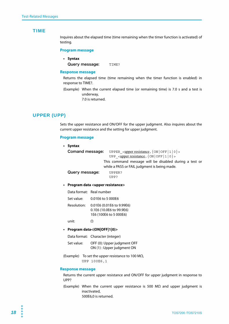
TIMEInquires about the elapsed time (time remaining when the timer function is activated) oftesting.
Program message
• SyntaxQuery message: TIME?
Response messageReturns the elapsed time (time remaining when the timer function is enabled) inresponse to TIME?.
(Example) When the current elapsed time (or remaining time) is 7.0 s and a test isunderway,7.0 is returned.
UPPER (UPP)
Sets the upper resistance and ON/OFF for the upper judgment. Also inquires about thecurrent upper resistance and the setting for upper judgment.
Program message
• SyntaxComand message: UPPER_<upper resistance,{ON|OFF|1|0}>
UPP_<upper resistance,{ON|OFF|1|0}>This command message will be disabled during a test orwhile a PASS or FAIL judgment is being made.
Query message: UPPER?UPP?
• Program data <upper resistance>
Data format: Real number
Set value: 0.01E6 to 5 000E6
Resolution: 0.01E6 (0.01E6 to 9.99E6)0.1E6 (10.0E6 to 99.9E6)1E6 (100E6 to 5 000E6)
unit: Ω
• Program data<{ON|OFF|1|0}>
Data format: Character (integer)
Set value: OFF (0): Upper judgment OFFON (1) : Upper judgment ON
(Example) To set the upper resistance to 100 MΩ,UPP 100E6,1
Response messageReturns the current upper resistance and ON/OFF for upper judgment in response toUPP?
(Example) When the current upper resistance is 500 MΩ and upper judgment isinactivated,500E6,0 is returned.

TOS7200 /TOS7210S 19
Test-Related Messages
VDATA (VDAT)
Inquires about the monitored voltage value for a test. Returns a real-time voltage valueduring the test, and returns the previous test voltage after the test.
Program message
• SyntaxQuery message: VDATA?
VDAT?
Response messageReturns the monitored voltage in response to VDAT?
(Example) When the current monitored voltage value is 500 V,500 is returned.
WAITTIME (WTIM)
Sets the wait time (WAIT TIME) during a test. Also inquires about the value set for currentwait time.
Program message
• SyntaxComand message: WAITTIME_<wait time>
WTIM_<wait time>This command message will be disabled during a test orwhile a PASS or FAIL judgment is being made.
Query message: WAITTIME?WTIM?
• Program data
Data format: Real number
Set value: 0.3 to 10.0
Resolution: 0.1
unit: s
(Example) To set the wait time to 1 s,WTIM 1
Response messageReturns the current wait time in response to WTIM?
(Example) When the current wait time is 2.0 s,2.0 is returned.

20 TOS7200 /TOS7210S
System-Related Messages
System-Related Messages
This subsection explains the device messages for items to be set on the System screen.
PASSHOLD (PHOL)
Sets ON/OFF for the pass hold for a PASS judgment. Also inquires about the currentsetting for pass hold.
Program message
• SyntaxComand message: PASSHOLD_<{ON|OFF|1|0}>
PHOL_<{ON|OFF|1|0}>
This command message will be disabled during a test orwhile a PASS or FAIL judgment is being made.
Query message: PASSHOLD?PHOL?
• Program data
Data format: Character (integer)
Set value: OFF (0): Pass hold OFFON (1) : Pass hold ON
(Example) To set pass hold to ON,PHOL ON
Response messageReturns the current pass hold in response to PHOL?
(Example) When the current pass hold is OFF,0 is returned.
BUZZERVOL (BVOL)
Sets the buzzer volume. Also inquires about the current buzzer volume.
Program message
• SyntaxComand message: BUZZERVOL_<set value>
BVOL_<set value>This command message will be disabled during a test orwhile a PASS or FAIL judgment is being made.
Query message: BUZZERVOL?BVOL?
• Program data
Data format: Integer
Set value: 0 to 9
Resolution: 1
(Example) To set the buzzer volume to 5,BVOL 5
TOS7200 /TOS7210S 21
System-Related Messages
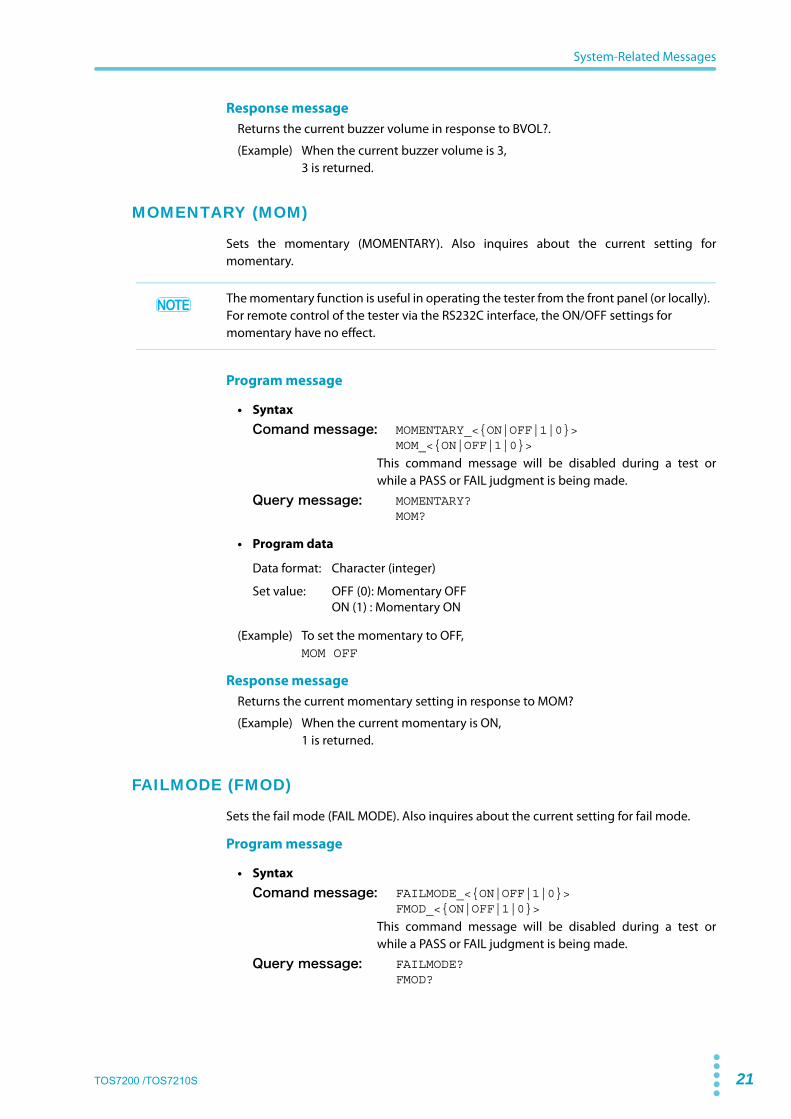
Response messageReturns the current buzzer volume in response to BVOL?.
(Example) When the current buzzer volume is 3,3 is returned.
MOMENTARY (MOM)
Sets the momentary (MOMENTARY). Also inquires about the current setting formomentary.
Program message
• SyntaxComand message: MOMENTARY_<{ON|OFF|1|0}>
MOM_<{ON|OFF|1|0}>
This command message will be disabled during a test orwhile a PASS or FAIL judgment is being made.
Query message: MOMENTARY?MOM?
• Program data
Data format: Character (integer)
Set value: OFF (0): Momentary OFFON (1) : Momentary ON
(Example) To set the momentary to OFF,MOM OFF
Response messageReturns the current momentary setting in response to MOM?
(Example) When the current momentary is ON,1 is returned.
FAILMODE (FMOD)
Sets the fail mode (FAIL MODE). Also inquires about the current setting for fail mode.
Program message
• SyntaxComand message: FAILMODE_<{ON|OFF|1|0}>
FMOD_<{ON|OFF|1|0}>
This command message will be disabled during a test orwhile a PASS or FAIL judgment is being made.
Query message: FAILMODE?FMOD?
The momentary function is useful in operating the tester from the front panel (or locally). For remote control of the tester via the RS232C interface, the ON/OFF settings for momentary have no effect.

22 TOS7200 /TOS7210S
System-Related Messages
• Program data
Data format: Character (integer)
Set value: OFF (0): Fail mode OFFON (1) : Fail mode ON
(Example) To set fail mode to OFF,FMOD OFF
Response messageReturns the current fail mode setting in response to FMOD?
(Example) When the current fail mode is ON,1 is returned.
DOUBLEACTION (DAC)
Sets the double-action mode (DOUBLE ACTION). Also inquires about the current settingfor double-action mode.
Program message
• SyntaxComand message: DOUBLEACTION_<{ON|OFF|1|0}>
DAC_<{ON|OFF|1|0}>
This command message will be disabled during a test orwhile a PASS or FAIL judgment is being made.
Query message: DOUBLEACTION?DAC?
• Program data
Data format: Character (integer)
Set value: OFF (0): Double-action mode OFFON (1) :Double-action mode ON
(Example) To set the double-action mode to OFF,DAC OFF
Response messageReturns the current setting for double-action mode in response to DAC?
(Example) When the current double-action mode is ON,1 is returned.
The double-action mode is useful in operating the tester from the front panel (locally). For remote control of the tester via the RS232C interface, the ON/OFF settings for double-action mode have no effect.

TOS7200 /TOS7210S 23
Memory-Related Messages
Memory-Related Messages
This subsection describes the device messages to be used in relation to memory.
RECALL (REC)
Recalls stored panel settings from memory.
Program message
• SyntaxComand message: RECALL_<memory No.>
REC_<memory No.>This command message will be disabled during a test orwhile a PASS or FAIL judgment is being made.
• Program data
Data format: Integer
Set value: 0 to 9
Resolution: 1
(Example) To recall a panel setting from memory number 9,REC 9
STORE (STOR)
Stores the current panel settings.
Program message
• SyntaxComand message: STORE_<memory No.>
STOR_<memory No.>This command message will be disabled during a test orwhile a PASS or FAIL judgment is being made.
• Program data
Data format: Integer
Set value: 0 to 9
Resolution: 1
(Example) To store the current panel settings for a tester in memory number 9,STOR 9

24 TOS7200 /TOS7210S
Memory-Related Messages
MEMORY (MEM)
Stores the test conditions in a specified memory number (location). Also inquires aboutthe contents of a specified memory number.
Program message
• SyntaxComand message: MEMORY (MEM)_<memory No., test voltage, lowerresistance, upper resistance, test time, upper judgment {ON|OFF|1|0}, timer{ON|OFF|1|0}, wait time>
This command message will be disabled during a test orwhile a PASS or FAIL judgment is being made.
Query message: MEMORY?_<memory No.>MEM?_<memory No.>
• Program data <memory No.>
Data format: Integer
Set value: 0 to 9
Resolution: 1
• Program data <test voltage>
Data format: Real number
Set value: TOS7200: 10 to 1020TOS7210s: 10 to 2040
Resolution: 1
unit: V
• Program data <lower resistance>
Data format: Real number
Set value: 0.01E6 to 5 000E6
Resolution: 0.01E6 (0.01E6 to 9.99E6)0.1E6 (10.0E6 to 99.9E6)1E6 (100E6 to 5 000E6)
unit: Ω
• Program data <upper resistance>
Data format: Real number
Set value: 0.01E6 to 5 000E6
Resolution: 0.01E6 (0.01E6 to 9.99E6)0.1E6 (10.0E6 to 99.9E6)1E6 (100E6 to 5 000E6)
unit: Ω
• Program data <test time>
Data format: Real number
Set value: 0.5 to 999
Resolution: 0.1 ( 0.5 to 99.9)1 (100 to 999)
unit: s

TOS7200 /TOS7210S 25
Memory-Related Messages
• Program data <upper judgment {ON|OFF|1|0}>
Data format: Character (integer)
Set value: OFF (0): Upper judgment OFFON (1) : Upper judgment ON
• Program data <timer {ON|OFF|1|0}>
Data format: Character (integer)
Set value: OFF (0): Timer OFFON (1) : Timer ON
• Program data <wait time>
Data format: Real number
Set value: 0.3 to 10.0
Resolution: 0.1
unit: s
Response messageReturns the contents of a specified memory number in response to MEM?_<memorynumber>.The memory contents are returned in the same order as for the program message.
(Example) When the program message inquires about the contents of memorynumber 9 and the memory contents are test voltage: 50 V; lower resistance:0.01 MW; upper resistance: 10.0 MW; test time: 2.0 s; upper judgment: OFF;timer: ON; and wait time: 0.5 s,50,0.01E6,10.0E6,2.0,0,1,0.5 is returned.
26 TOS7200 /TOS7210S
4 Registers
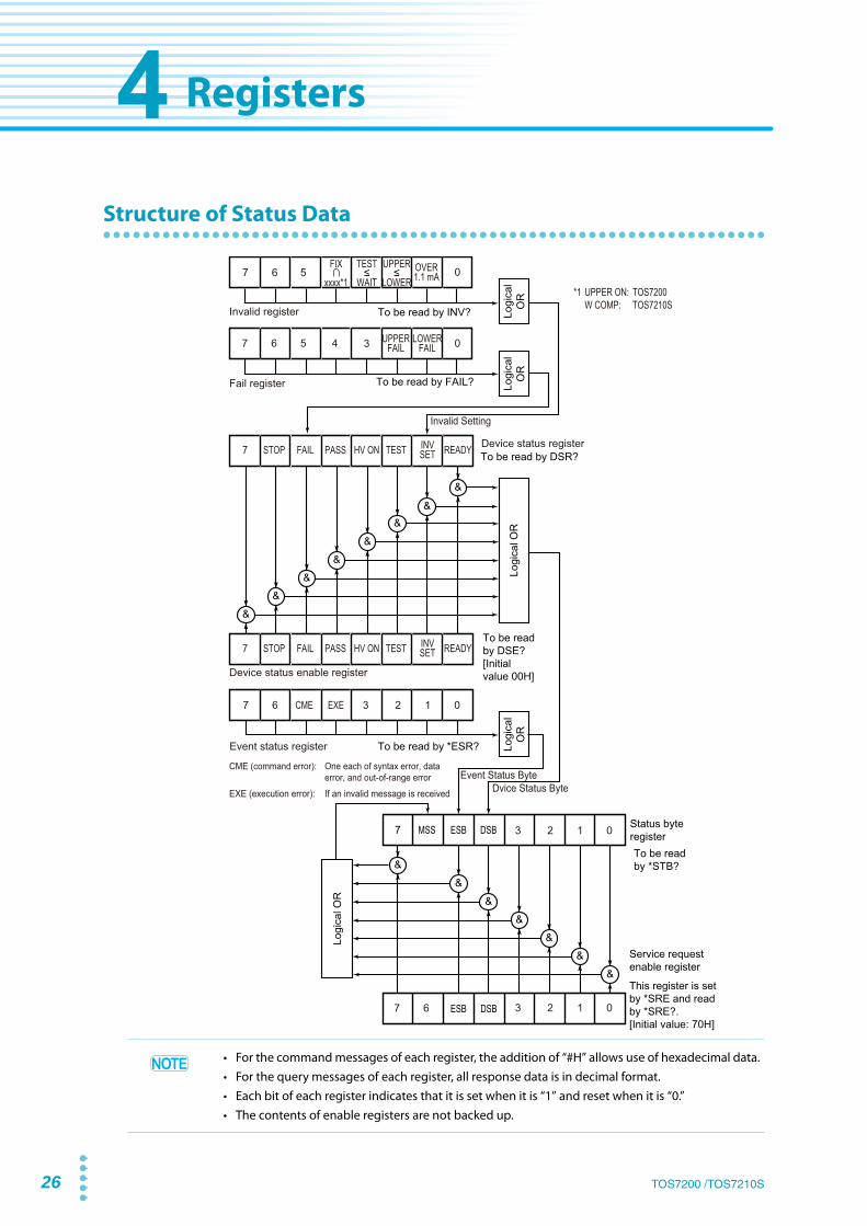
Structure of Status Data
7 ESBMSS DSB
ESB DSB
Device status enable register
Event status register
Logi
cal
OR
Logi
cal
OR
Logi
cal
OR
Logi
cal O
R
Logi
cal O
R
To be read by *STB?
Service request enable register
This register is set by *SRE and read by *SRE?.[Initial value: 70H]
To be read by DSR?
To be read by DSE?[Initial value 00H]
To be read by *ESR?
Status byte register
7 6
7 6
CME EXE 3 2 1 0
3 2 1 0
3 2 1 0
HV ON TESTFAILSTOP7 PASS READYINVSET
Invalid register To be read by INV?
7 6
Fail register To be read by FAIL?
7 6 5 4
5
3 0
0
UPPERFAIL
LOWERFAIL
OVER1.1 mA
HV ON TESTFAILSTOP7 PASS READYINVSET
&&
&&
&
&&
&&
&&
&
&&
&
Device status register
*1 UPPER ON: TOS7200 W COMP: TOS7210S
Invalid Setting
Dvice Status ByteEvent Status Byte
TEST
WAIT
FIX
xxxx*1
UPPER
LOWER
CME (command error): One each of syntax error, data error, and out-of-range errorEXE (execution error): If an invalid message is received
• For the command messages of each register, the addition of “#H” allows use of hexadecimal data.• For the query messages of each register, all response data is in decimal format.• Each bit of each register indicates that it is set when it is “1” and reset when it is “0.”• The contents of enable registers are not backed up.

TOS7200 /TOS7210S 27
Registers
Status Byte Register, Service Request Enable Register
Event Status Register
Device Status Register, Device Status Enable Register
Bit Description
7 Not used in the tester
6MSS(Master Summary Status)
This is the logical OR for the status byte register and service-request enable register and is read by *STB?.
5ESB(Standard Event Status Bit)
Indicates that any of the bits of the event status register has been set.
4DSB(Device Status Bit)
Indicates that any of the bits of the device status register has been set.
3 Not used in the tester
2 Not used in the tester
1 Not used in the tester
0 Not used in the tester
Bit Description
7 Not used in the tester
6 Not used in the tester
5CME (Command Error)
Indicates that a syntax error, data error, or out-of-range error has occurred.
4 EXE (Excution Error) Indicates that this bit has received an invalid message during a test.
3 Not used in the tester
2 Not used in the tester
1 Not used in the tester
0 Not used in the tester
Bit Description
7 Not used in the tester
6 STOP A test has stopped.
5 FAIL FAIL judgment
4 PASS PASS judgment
3 HV ON State of voltage output
2 TEST State of test voltage output
1INV SET (Invalid setting)
Invalid setting state in which the LOWER, UPPER, WAIT, or UPPER ON (TOS7200)/ W COMP (TOS7210s) LED is blinking
0 READY Ready state

28 TOS7200 /
Registers
Fail Register
Invalid Register
Error Register
Bit Description
7 Not used in the tester
6 Not used in the tester
5 Not used in the tester
4 Not used in the tester
3 Not used in the tester
2UPPER FAIL Indicates that a FAIL judgment has been made with respect to the
upper resistance.
1LOWER FAIL Indicates that a FAIL judgment has been made with respect to the
lower resistance.
0 Not used in the tester
Bit Description
7 Not used in the tester
6 Not used in the tester
5 Not used in the tester
4 FIX ∩ xxxx*1
*1. UPPER ON (TOS7200) / W COMP (TOS7210S)
Set if the fixed range is selected with the upper judgment set to ON.
3TEST ≤ WAIT Set if the wait time is equal to or greater than the test time with the
timer function set to ON.
2UPPER ≤ LOWER Set if the lower resistance is equal to or above the upper resistance with
the upper and lower judgments set to ON.
1OVER 1.1 mA Set if a value obtained by dividing the test voltage by the lower
resistance exceeds 1.1 mA.
0 Not used in the tester
Bit Description
7 Not used in the tester
6 Not used in the tester
5 Not used in the tester
4 Not used in the tester
3 Invalid message Indicates that an invalid message has been received.
2 Out-of-range error Indicates that an out-of-range error has occurred.
1 Data Error Indicates that a data error has occurred.
0 Syntax Error Indicates that a header error has occurred.

TOS7200 /TOS7210S 29
5 List of Device Messages
An item in parentheses in the Header column indicates the abbreviation of a devicemessage.
Note: A check (✔) is used to indicate available device messages, even during a test orwhile a PASS or FAIL judgment is being made, while a cross (✘) is used to indicatethose not available.
List of Register-Related and General Purpose Device Messages
HeaderData
Function and response data NoteMin Max Resolution Unit
*CLS Clears the status byte register, event status register, device status register, fail register, invalid setting register, and error register.
✔
*ESR? Returns the value of the event status register and clears this register. ✔
*IDN? Returns “KIKUSUI ELECTRONICS CORP.,TOSmmmm,0,x.xx.mmmm: “7200” for the TOS7200, “7210S” for the TOS7210S.
✔
*RST Initializes the device (to the factory default settings). ✔
*SRE 0 255 Sets the service request enable register. ✔
*SRE? Returns the value of the service request enable register. ✘
*STB? Returns the value of the status byte register. ✔
CLR Clears all registers and sets a stop flag (this message is the same as DCL). ✔
DSE 0 255 Sets the device status enable register. ✘
DSE? Returns the value of the device status enable register. ✔
DSR? Returns the value of the device status register. ✔
ERR? Returns the value of the error register and clears this register. ✔
FAIL? Returns the value of the fail register. ✔
INVALID?(INV?)
Returns the value of the invalid setting register.Returns the value of the invalid setting register. ✔
SILENT(SIL) 0 1
Acknowledge message✔
SILENT?(SIL?)
Returns the value of an acknowledge message.✔
START(STAR)
Starts a test.✘
STOP Stops a test. Also cancels a FAIL or PASS judgment or PASS HOLD status. ✔

30 TOS7200 /TOS7210S
List of Device Messages
List of Device Messages Relating to Tests
HeaderData
Function and response data NoteMin Max
Resolution
Unit
AUTORANGE(AUTOR) OFF(0) ON (1)
Sets ON/OFF for auto-range.✘
AUTORANGE?(AUTOR?)
Returns ON/OFF for auto-range .(ON: 1; OFF: 0) ✔
LOWER(LOW)
0.01E6 9.996 0.01E6 Ω Lower resistance
✘10.0E6 99.9E6 0.1E6 Ω
100E6 5000E6 1E6 Ω
OFF (0) ON (1) Sets ON/OFF for lower judgment.
LOWER?(LOW?)
Returns the lower resistance and ON/OFF for lower judgment.(0.01E6 Ω to 5000E6 Ω, ON:1, OFF:0)
✔
MON? Returns a monitored voltage (TOS7200: 0 V to 1 020 V, TOS7210S: 0 V to 2040 V), monitored resistance (0.01E6 Ω to 5 000E6 Ω), monitored current (TOS7210S only 0.000 μA to 1900 μA), and elapsed (remaining) time (0 s to 999 s), in that order, delimiting them with “ , ”. Returns the previous test results in any case other than a test in progress.
RDATA?(RDAT?) Returns a monitored resistance value.(0.01E6 Ω to 5000E6 Ω)
✔
IDATA?(IDAT?)(TOS7210S only)
Returns a monitored current value.(0.000 μA to 1900 μA) ✔
TIMER 0.5 99.9 0.1 s Timer set value
✘100 999 1 s
OFF (0) ON (1) Sets ON/OFF for the timer function.
TIMER? Returns the timer set value and ON/OFF for the timer function.(0.5 s to 999 s, ON:1, OFF:0)
✔
TESTV(TES) 10TOS7200: 1020
TOS7210S: 20401 V
Sets the test voltage.✘
TESTV?(TES?)
Returns the test-voltage set value.(TOS7200: 0 V to 1020 V, TOS7210S: 0 V to 2040 V) ✔
POLARITY(POL)(TOS7210S only)
0 1Sets the test voltage polarity.(Positive: 1, negative: 0) ✘
POLARITY?(POL?)(TOS7210S only)
Returns the test voltage polarity.(Positive: 1, negative: 0) ✔
TIME? Returns the elapsed (remaining) time. ( 0 s to 999 s) When TIMER is OFF, the elapsed time is returned.When TIMER is ON, the remaining test time is returned.
✔
UPPER(UPP)
0.01E6 9.99E6 0.01E6 Ω Upper resistance
✘10.0E6 99.9E6 0.1E6 Ω
100E6 5000E6 1E6 Ω
OFF (0) ON (1) Sets ON/OFF for upper judgment.
UPPER?(UPP?)
Returns the upper resistance and ON/OFF for upper judgment (0.01E6 Ω to 5000E6 Ω, ON:1, OFF:0) ✔
VDATA?(VDAT?)
Monitored voltage (TOS7200: 0 V to 1020 V, TOS7210S: 0 V to 2040 V)
✔
WAITTIME(WTIM) 0.3 10 0.1 s Sets the wait time. ✘
WAITTIME? (WTIM?)
Returns the set value for the wait time.(0.3 s to 10.0 s) ✔

TOS7200 /TOS7210S 31
List of Device Messages
List of System-Related Device Messages
HeaderData
Function and response data NoteMin Max Resolution Unit
PASSHOLD(PHOL) OFF (0) ON (1)
Sets ON/OFF for pass hold.✘
PASSHOLD?(PHOL?)
Returns ON/OFF for pass hold. (ON:1, OFF:0) ✔
BUZZERVOL(BVOL) 0 9 1
Sets the buzzer volume.✘
BUZZERVOL?(BVOL?)
Sets the set value of the buzzer volume.(0 to 9) ✔
MOMENTARY(MOM) OFF (0) ON (1)
Sets ON/OFF for momentary.✘
MOMENTARY? (MOM?)
Returns ON/OFF for momentary.(ON: 1; OFF: 0) ✔
FAILMODE(FMOD) OFF (0) ON (1)
Sets ON/OFF for fail mode.✘
FAILMODE?(FMOD?)
Returns ON/OFF for fail mode.(ON: 1; OFF: 0) ✔
DOUBLEACTION(DAC) OFF (0) ON (1)
Sets ON/OFF for double action.✘
DOUBLEACTION?(DAC?)
Returns ON/OFF for double action.(ON: 1; OFF: 0) ✔

32 TOS7200 /TOS7210S
List of Device Messages
List of Memory-Related Device Messages
HeaderData
Function and response data NoteMin Max Resolution Unit
RECALL(REC) 0 9 1
Recalls memory.✘
STORE(STOR) 0 9 1
Stores the current panel settings in memory.✘
MEMORY(MEM)
0 9 1Stores the following data in a specified memory number.
✘
10TOS7200: 1020
TOS7210S: 20401 V
Test voltage
0.01E6 9.99E6 0.01E6 Ω Lower resistance
10.0E6 99.9E6 0.1E6 Ω
100E6 5000E6 1E6 Ω
0.01E6 9.99E6 0.01E6 Ω Upper resistance
10.0E6 99.9E6 0.1E6 Ω
100E6 5000E6 1E6 Ω
0.5 99.9 0.1 s Test time
100 999 1 s
OFF (0) ON (1) Sets ON/OFF for upper judgment.
OFF (0) ON (1) Timer ON/OFF
0.3 10 0.1 s Wait time
MEMORY? (MEM?) 0 9 1
Returns the contents of a specified memory number (test voltage, lower resistance, upper resistance, test time, ON/OFF for upper judgment, timer ON/OFF, and wait time)
✔

TOS7200 /TOS7210S 33
AUTORANGE(AUTOR) ................................................................. 14BUZZERVOL (BVOL) ..................................................................... 20CLR .................................................................................................... 11DOUBLEACTION (DAC) ............................................................... 22DSE .................................................................................................... 11DSR .................................................................................................... 11ERR .................................................................................................... 12FAIL ................................................................................................... 12FAILMODE (FMOD) ...................................................................... 21IDATA (IDAT) .................................................................................. 16INVALID (INV) ................................................................................. 12LOWER (LOW) ................................................................................ 14MEMORY (MEM) ............................................................................ 24MOMENTARY (MOM) ................................................................... 21MON .................................................................................................. 15PASSHOLD (PHOL) ....................................................................... 20POLARITY(POL) .............................................................................. 17RDATA (RDAT) ............................................................................... 15RECALL (REC) ................................................................................. 23SILENT (SIL) ..................................................................................... 13START ............................................................................................... 13STOP ................................................................................................. 13STORE (STOR) ................................................................................. 23TESTV (TES) ..................................................................................... 17TIME .................................................................................................. 18TIMER ................................................................................................ 16UPPER (UPP) ................................................................................... 18VDATA (VDAT) ............................................................................... 19WAITTIME (WTIM) ......................................................................... 19*CLS ......................................................................................................9*ESR ......................................................................................................9*IDN .....................................................................................................9*RST ................................................................................................... 10*SRE ................................................................................................... 10*STB ................................................................................................... 10
Ddevice message ...............................................................................8
LLOCAL key ..........................................................................................5localmode, switching .....................................................................5
Mmessage
list ....................................................................................... 29
Pprogram message ...........................................................................6
RRS232C flow control ...................................................................... 4RS232C interface ............................................................................. 3RS232C protocol ............................................................................. 4
Tterminator ......................................................................................... 7
Index

34 TOS7200 /TOS7210S

KIKUSUI ELECTRONICS CORP.
http://www.kikusui.co.jp/en
1-1-3 Higashiyamata, Tsuzuki-ku, Yokohama, 224-0023, JapanTel: +81-45-482-6353 Fax: +81-45-482-6261
Website
If the manual gets lost or soiled, a new copy can be provided for a fee. In either case, please contact your Kikusui agent or distributor. At that time, inform your agent or distrib-utor of the “Part No.” written on the front cover of this manual.Every effort has been made to ensure the accuracy of this manual. However, if you have any questions or find any errors or omissions, please contact your Kikusui agent or distributor.After you have finished reading this manual, store it so that you can use it for reference at any time.