Torsional Strengthening of RC Box Beams Using...
12
IOSR Journal of Mechanical and Civil Engineering (IOSR-JMCE) e-ISSN: 2278-1684,p-ISSN: 2320-334X, Volume 12, Issue 2 Ver. VII (Mar - Apr. 2015), PP 30-41 www.iosrjournals.org DOI: 10.9790/1684-12273041 www.iosrjournals.org 30 | Page Torsional Strengthening of RC Box Beams Using External Prestressing Technique Abd El-HakimKhalil 1 , Emad Etman 1 , Ahmed Atta 2 , Sabry Fayed 3 1 (Prof. of Concrete Structures, Faculty of Engineering, Tanta University, Egypt.) 2 ( Associate Professor, Faculty of Engineering, Tanta University, Egypt.) 3 (Master Student, Faculty of Engineering, Kafrelsheikh University, Egypt (Corresponding author)) Abstract:This paper investigate the behavior of reinforced concrete box beam under pure torsion.The box beam was strengthened experimentally with external prestressing technique (EPT) using two different directions horizontally and vertically. Ten strengthened box beams, with and without web opening, were tested. The study emphasizes prestressing direction and transverse opening dimensions. The failure modes, torsional capacities, rotation, stress in external tendon and strain in internal reinforcements were studied in details. The experimental results indicated that the contribution of EPT strengthening using the horizontal and vertical directions to torsional capacity of box beam, with and without opening, is significant with ratios ranged between31% to 58% respectively. The contribution was enhanced using the vertical direction. It was found that the presence of transverse openings decrease the torsional capacity. While EPT strengthening at the opening increased torsional capacity compared to beams without opening. A computing procedure is presented to predict the torsional capacities of RC beams under torsion. The calculated results fit well with the experimental one. Keywords:Strengthening, Box Beams, External Prestressing, pure torsion, web openings. I. Introduction Many building and bridge elements are subjected to significant equilibrium torsional moments that may require repair and strengthening. Torsional strengthening of concrete members may be achieve by one of the following methods: (1) increasing the member cross-sectional area, (2) adding transverse reinforcement , (3) using externally bonded steel plates, (4) applying an axial load to the member by External prestressing. External prestressing may be defined as a prestress introduced by tendons located outside a section of a structural member, only connected to the member through deviators and end-anchorages. The advantages ofsuch technique are; smaller sectional areas, ease in inspection of the tendons and in their replacement and low friction losses. This type of prestressing can be applied to both new and existing structures that need to be strengthened due to several reasons such as: changes in use, deficiencies in design or construction phase and structural degradation. Strengthening structural elements subjected to torsion using EPT enable the designer to selectively increase their ductility, and torsional capacity. In an external prestressing system, there is no strain compatibility between the cable and the concrete for whole cross-sections, the increment of cable strain must be evaluated by taking into account the whole structure, rather than performing the calculation at each section, independently (Ali, 2013). Structural performance of damaged girder can be recovered and improved by external post tension. The level of external prestressing force required in strengthening depends directly on the level of damage due to overloading. The effect of damage's levels on flexural rigidity, crack and deflection of the test girder was studied by Phuwadolpaisarn, (2013).Experimental investigations on strengtheningof RC beams by external prestressing have been carried out(Manisekar, 2014).It was observed that the ultimate load carrying capacity of strengthened members have increased by 48 % and 17 % for single-draped tendon profile and straight tendon profile respectively. Naser, (2012) studied the application of external prestressing tendons for strengthening of existing bridges which has been used in many countries since the 1950s and has been found to provide an efficient and economical solution in a wide range of the bridge types and conditions.Shear strengthening, flexural strengtheningand torsional strengthening of reinforcement concrete beams using composite materials were studied by several researchers and investigators at several institutions. Especially, studying the strengthening of structural elements using EPT was studied by Atta, (2012), El-Shafiey and Atta, (2012), Jeyasehar, (2008), Matta and et al, (2009) and Algorafi and et al, (2010). The reasons for the lack of research in this area include the specialized nature of the problem and the difficulties in conducting realistic tests and representative analyses. It is also a reason that few practical structures need to be strengthened to increase the strengthening of RC beams especially torsional strengthening. In the design of many concrete structural elements, torsion is significant and has to be considered such as curved structures, members of a space frame, eccentrically loaded beams, ring beams at the bottom of circular tanks, etc. For this reason, many researchers such as
-
Upload
nguyencong -
Category
Documents
-
view
218 -
download
2
Transcript of Torsional Strengthening of RC Box Beams Using...

IOSR Journal of Mechanical and Civil Engineering (IOSR-JMCE)
e-ISSN: 2278-1684,p-ISSN: 2320-334X, Volume 12, Issue 2 Ver. VII (Mar - Apr. 2015), PP 30-41
www.iosrjournals.org
DOI: 10.9790/1684-12273041 www.iosrjournals.org 30 | Page
Torsional Strengthening of RC Box Beams Using External
Prestressing Technique
Abd El-HakimKhalil1, Emad Etman
1, Ahmed Atta
2, Sabry Fayed
3
1(Prof. of Concrete Structures, Faculty of Engineering, Tanta University, Egypt.)
2( Associate Professor, Faculty of Engineering, Tanta University, Egypt.)
3(Master Student, Faculty of Engineering, Kafrelsheikh University, Egypt(Corresponding author))
Abstract:This paper investigate the behavior of reinforced concrete box beam under pure torsion.The box beam
was strengthened experimentally with external prestressing technique (EPT) using two different directions
horizontally and vertically. Ten strengthened box beams, with and without web opening, were tested. The study
emphasizes prestressing direction and transverse opening dimensions. The failure modes, torsional capacities,
rotation, stress in external tendon and strain in internal reinforcements were studied in details. The
experimental results indicated that the contribution of EPT strengthening using the horizontal and vertical
directions to torsional capacity of box beam, with and without opening, is significant with ratios ranged
between31% to 58% respectively. The contribution was enhanced using the vertical direction. It was found that
the presence of transverse openings decrease the torsional capacity. While EPT strengthening at the opening
increased torsional capacity compared to beams without opening. A computing procedure is presented to
predict the torsional capacities of RC beams under torsion. The calculated results fit well with the experimental
one. Keywords:Strengthening, Box Beams, External Prestressing, pure torsion, web openings.
I. Introduction Many building and bridge elements are subjected to significant equilibrium torsional moments that may
require repair and strengthening. Torsional strengthening of concrete members may be achieve by one of the
following methods: (1) increasing the member cross-sectional area, (2) adding transverse reinforcement , (3)
using externally bonded steel plates, (4) applying an axial load to the member by External prestressing. External
prestressing may be defined as a prestress introduced by tendons located outside a section of a structural
member, only connected to the member through deviators and end-anchorages. The advantages ofsuch
technique are; smaller sectional areas, ease in inspection of the tendons and in their replacement and low friction
losses. This type of prestressing can be applied to both new and existing structures that need to be strengthened
due to several reasons such as: changes in use, deficiencies in design or construction phase and structural
degradation. Strengthening structural elements subjected to torsion using EPT enable the designer to selectively
increase their ductility, and torsional capacity. In an external prestressing system, there is no strain compatibility
between the cable and the concrete for whole cross-sections, the increment of cable strain must be evaluated by
taking into account the whole structure, rather than performing the calculation at each section, independently
(Ali, 2013). Structural performance of damaged girder can be recovered and improved by external post tension.
The level of external prestressing force required in strengthening depends directly on the level of damage due to
overloading. The effect of damage's levels on flexural rigidity, crack and deflection of the test girder was
studied by Phuwadolpaisarn, (2013).Experimental investigations on strengtheningof RC beams by external
prestressing have been carried out(Manisekar, 2014).It was observed that the ultimate load carrying capacity of
strengthened members have increased by 48 % and 17 % for single-draped tendon profile and straight tendon
profile respectively.
Naser, (2012) studied the application of external prestressing tendons for strengthening of existing
bridges which has been used in many countries since the 1950s and has been found to provide an efficient and
economical solution in a wide range of the bridge types and conditions.Shear strengthening, flexural
strengtheningand torsional strengthening of reinforcement concrete beams using composite materials were
studied by several researchers and investigators at several institutions. Especially, studying the strengthening of
structural elements using EPT was studied by Atta, (2012), El-Shafiey and Atta, (2012), Jeyasehar, (2008),
Matta and et al, (2009) and Algorafi and et al, (2010). The reasons for the lack of research in this area include
the specialized nature of the problem and the difficulties in conducting realistic tests and representative
analyses. It is also a reason that few practical structures need to be strengthened to increase the strengthening of
RC beams especially torsional strengthening. In the design of many concrete structural elements, torsion is
significant and has to be considered such as curved structures, members of a space frame, eccentrically loaded
beams, ring beams at the bottom of circular tanks, etc. For this reason, many researchers such as

Torsional Strengthening of RC Box Beams Using External Prestressing Technique
DOI: 10.9790/1684-12273041 www.iosrjournals.org 31 | Page
Varghese,(2010),Jing, (2007) and Panchacharam, (2002)have paid more attentions to the studies of torsional
capacity and bending torque coupling effect. Some researchers studied RC beams under pure torsion such as
Mahaidi, (2007), Varghese, (2010), Abdeldjelil, (2004) and Mohammed, (1983).
The author Bernardo etal, (2012, 2011, and 2009), have many of works about the torsion.Bernardo
etal., (2013) presented a study on the plastic behavior and twist capacity of High-Strength Concrete hollow
beams under pure torsion. The plastic twist capacity of the beams was studied by using a Plastic Trend
Parameter.Bernardo etal, (2012) developed a new computation procedure to predict the overall behaviour of
reinforced concrete beams under torsion.They generalized the Space-Truss Analogy, by using the VATM
formulation, in order to make it able to predict theentire T–ϴ curve of RC beams under torsion, and not only the
points corresponding to the ultimate behaviour.Bernardo etal., (2008)developed a simple computation procedure
to predict the general behaviour of reinforced concrete beams under torsion. Both plain and hollow normal
strength concrete beams are considered. Different theoretical models are used to reflect the actual behaviour of
the beams in the various phases of loading.Bernardo etal., (2014) presented the failure mode and the
development of cracking analysis in high strength hollow beams under pure torsion up to failure.In modern
construction, transverse openings in reinforced concrete beams are often provided for the passage of utility ducts
and pipes. The presence of transverse openings will transform simple beam behaviour to more complex
behaviour, as they induce a sudden change in the dimension of the beam’s cross section. The ultimate strength,
shear strength, crack width and stiffness may also be seriously affected. Some researchers studied these
parameters such as Mansur, (1999), Mohammed, (1983), Abdeldjelil, (2004) and Ahmed and et al, (2012). The
present study is rather unique in addressing torsional strengthening of reinforced concrete (RC) box beams
under torsion using external prestressing technique (EPT).
II. Experimental Work 2.1. Test specimens and strengthening schemes
The experimental work consisted of ten identical RC single cell square box beams having cross section
of 500mm x 500mm.The wall thickness is 100mm and the overallspan of the beam was 2600mm while the
loaded span was 2300mm. The concrete dimensions of beams were chosen similar to previous works such as
Algorafi and et al, 2010 and Mahaidia, 2007. The beam section was designed according to the Egyptian code,
ECCS 203-2001. All the tested specimens were reinforced with four12mm diameter longitudinal bars in both
bottom and topflanges in addition to two12mm diameter longitudinal bars in each side. Diameter of 8mm
stirrups spaced by167mm was used throughout the beam span.The reinforcement was used on outer parameter
of walls because wall thickness exceeded 1/6 box section width according to Egyptian code, ECCS 203-2001.
The cell of size 300x300 mm was concentric with the beam section. The cell extended for 1000mm measured
from each side of the center line of the beam.Beyond the cell, whole beam section (500x500mm) was solid
concrete. Tested specimens were divided into two groups; each group consisted of five specimens. The first
group casted without transverse opening while the second group casted with transverse opening.Figure 1 shows
details of the specimens without openings and with openings. For second group, the opening sizes were
150x150mm, 150x300mm, and 150x450mm. The openings were made in two opposite side walls. Main
reinforcement (stirrups) was almost kept the same except the stirrups intersecting with opening were
discontinued as shown in figure1.For each group, one specimen was control beam while the other four beams
were strengthened using external prestressing technique (EPT). For the first group, one specimen was loaded up
to 70% of ultimate torsional moment (first crack of control beam) then repaired using longitudinal EPT. Three
strengthening techniques were used. The first was done by using external prestressing longitudinally tendons.
The second strengthening technique was vertical external tendons at the middle of the beam to apply post
tension force around the opening. The last strengthening technique was similar to the previous technique with
the difference that post tension force was spreaded uniformly along the whole span.Three strengthening
techniques were shown in figure 2.Table 1 shows the test matrix and specimens notation.
Torsional Strengthening of RC Box Beams Using External Prestressing Technique
DOI: 10.9790/1684-12273041 www.iosrjournals.org 32 | Page

Torsional Strengthening of RC Box Beams Using External Prestressing Technique
DOI: 10.9790/1684-12273041 www.iosrjournals.org 33 | Page
Table 1Retrofit Scheme of Specimens
2.2 Material properties
Concretewith compressive cube strength of 35 N/mm2was used for casting of all specimens. The
concrete mix consisted of fine aggregate (1500 Kg/m3), well-graded coarse aggregate (10-20mm) of 1250
Kg/m3, ordinary Portland cement (350 Kg/m
3), water cement ration of 0.6 and admixture.In order to attain
acceptable level of workability of the fresh concrete, super plasticizer (Sikament-163M) was used with ratio 1
ltr/100kg of cement weight. Stirrups were made from mild steel have yield stress (ƒyv) of 250 N/mm2 while
longitudinal bars were made from high tensile steel have yield stress (ƒyl) of 400 N/mm2. Bars of diameter
12mm were used for external prestressing. The direct tensile test was conducted for each bar type and the results
were shown in figure 3 and listed in table 2.
Table 2 The Test Results of EPT bars
Description 0.2%yield
Strength MPa Tensile
strength MPa Elongation
% Reduction of Area %
Stainless steel bright bars 728 800 20.0 68.0
2.3 Test setup and instrumentations
All beams were tested under pure torsion as shown schematically in figure 4. The load was applied
using a hydraulic actuator of 450 kN capacity. A load cell was attached to the loading actuator to record the
applied load at 3 seconds.The load was applied through a diagonally placed steel spreader beam at the end of the

Torsional Strengthening of RC Box Beams Using External Prestressing Technique
DOI: 10.9790/1684-12273041 www.iosrjournals.org 34 | Page
two steel arms. These arms were fixed at the end parts of each tested beam. Horizontal movements of a vertical
side of the beam were measured using LVDT. Strains of the EPT barsand internal reinforcements (stirrups and
longitudinal bars) were measured using electrical strain gauges.
III. Results And Discussion
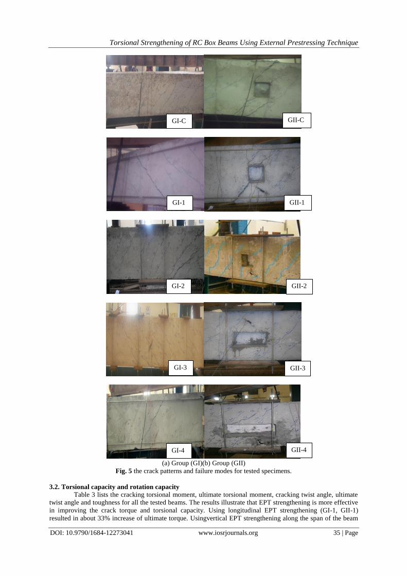
3.1. Cracks patterns
The progress of cracks provided useful information regarding the failure mechanism of tested
specimens. First crack of all specimens occurred at mid span and increased gradually. When the torque moment
was increased, cracks appeared on each side and finally took the spiral shape. At failure, extensive parallel
cracks at 400-450 on each side along the span of the beam were observed as shown in Figure 5. For specimens
without opening, group (GI), the cracksof strengthened beam (GI-2) spread with smaller number and develop
more slowly in strengthening zone because the EPTprevented the increment of the crack's width. Also the
failure position of two specimens (GI-C) and (GI-1) took place at mid span because section at the two ends of
the beam was solid with highertorsional resistance. For specimen (GI-3), due to uniform distributing of EPT
along the beam, the cracks distributed between external prestressing bars and not continuously around the
specimen with increasing in cracks number.The location of the failure occurred at the distance between last
external prestressing bar and the solid end due to good strengthening configuration along the beam. For
specimen (GI-2), which strengthened at mid span, the cracks spread in theunstrengthned zone and the failure
occurred at the same zone. That may be described as a result of EPT.
For specimens with opening,group (GII), it was noticed that the first crack for all specimens took place
at the corner of the opening.Both specimen GII-C and specimen GII-1, were strengthened longitudinally, and
hadthe same crack pattern and the same mode of failure. Thisis due to the weakness at the opening section is the
reasonbehind such behaviour. The effect of EPT is subjected to only on increasing the normal force value. That
led only to increase the value of failure load.For specimens (GII-2, GII-3), that were strengthened vertically at
opening, the failure was observed outside the opening area as a result of the existing of EPT at vertical direction
near the ends of the opening. This type of strengthening decreased the spreadof the cracks from corners and
transfer the failure to be outside the opening zone. The failure appears inside the opening zone in GII-4 while
itappears outside the opening zone in GII-2. That difference is due to the ofsmall opening size of sample (GII-2)
and large opening size of sample(GII-4) (Ahmed and Fayyedh, 2012).
Torsional Strengthening of RC Box Beams Using External Prestressing Technique
DOI: 10.9790/1684-12273041 www.iosrjournals.org 35 | Page
(a) Group (GI)(b) Group (GII)
Fig. 5 the crack patterns and failure modes for tested specimens.
3.2. Torsional capacity and rotation capacity
Table 3 lists the cracking torsional moment, ultimate torsional moment, cracking twist angle, ultimate
twist angle and toughness for all the tested beams. The results illustrate that EPT strengthening is more effective
in improving the crack torque and torsional capacity. Using longitudinal EPT strengthening (GI-1, GII-1)
resulted in about 33% increase of ultimate torque. Usingvertical EPT strengthening along the span of the beam
GI-C
GI-3
GI-1
GI-4
GI-2
GII-C
GII-1
GII-2
GII-3
GII-4

Torsional Strengthening of RC Box Beams Using External Prestressing Technique
DOI: 10.9790/1684-12273041 www.iosrjournals.org 36 | Page
(GI-3) improved the torsional capacity up to 58%. Theprestressing compression force acted against principal
tensile stress(Tarek El-Shafiey and Ahmed Atta,2012) which increase of ultimate torque in specimen GI-1,
specimen GII-1, and specimen GI-3. EPT repairing (GI-4) was slightlyaffected the crack torque and torsional
capacity. The presence of openings seems to be more effective in decreasing the crack torque and torsional
capacitybecause the opening decreased the section rigidity.Hence it becamethe weakness positionthrough the
whole beam. In a Comparison with the reference beam (GI-C), the crack torque and torsional capacity of
specimen (GII-C), with opening 150mmx150mm, are decreased by 15% and 11% respectively. However,
compared to the reference beam (GI-C), the torsional capacity of specimens (GII-3, GII-4) is decreased by 12%
and 17% respectively.
Figure 6 shows the relationship between torque and angle of rotations for all beams. According to the
results obtained fromtable 3 and Fig. 6,the EPT strengthening can obviously change the deformation capacity of
box beams. For all specimens, test results indicated that the angle of rotation was approximately constant at
about 10x10-6
radian until occurrence of the first crack then increased gradually until failure. The longitudinal
and vertical strengthening technique had a simple effect on the crack angle of rotation as the test results
indicated. At the same level of torque, the rotation of strengthened beams was smaller than the rotation of
control beams. The reason was the restraint due to prestressing force. The curveswhichare shown in figure
6indicated that at a given value of rotation, the strengthened beams carried additional torque than control
beams.Comparedto the control beam (GI-C), the ultimate twist angle of (GI-1) is increased by 133%, because
the tendons were placed horizontally outside the beam and that allow to free rotation of the beam. Moreoverfor
beam GI-2,the ultimate twist angle is decreased by 40%.For beams GI-3 and GI-4, the ultimate twist angle is
increased by 133% and 17% respectively. The increase in specimens GI-3 was due to uniform distribution of
tendons along beam length. On the other hand, the decrease in specimens GI-2may be due to high rigidity of two
plates at mid span. For specimen GI-2, the maximum angle of rotation was smaller than the maximum angle of
rotation of GI-3 because the plates of strengthening placed at mid span restrained the rotation and divided the
span into two parts. Transverse openings have effect on the rotation. For two control beams the opening
increased the maximum angle of rotation by 10% because the weakness results from opening. For the two
beams strengthened longitudinally (GI-1, GII-1) the opening increased the maximum angle of rotation by 14%
due to the weakness of the opening cross section. The beams strengthened vertically (GI-2 and GII-2) the
rotation was less than the control beams due to the restriction of rotation resulted from the existing high rigidity
prestressing plates.
Table 3 The Experimental Test Results
spec
imen
Cracking torque
(kN.m)
Crack twist angle
(rad.)x10-6
Ultimate torque
(kN.m)
Ultimate twist angle
(rad.) x10-6
Increase of ultimate torque
(%)
Toughness (kN.m.rad.
x10-4)
GI-C 36 10 62.3 300 - 156
GI-1 46.8 10 82.5 750 33 450
GI-2 52 12 66.4 200 6.5 116
GI-3 63.7 26 98 700 58 581
GI-4 36.1 15 61 350 - 146
GII-C 30.5 9.8 55.5 340 - 140
GII-1 40 13 73.1 800 31.7 452
GII-2 43.65 8 62.8 220 13.2 113
GII-3 40.5 8.5 58.4 400 -12 197
GII-4 33.75 9 55 550 -17.2 267

Torsional Strengthening of RC Box Beams Using External Prestressing Technique
DOI: 10.9790/1684-12273041 www.iosrjournals.org 37 | Page
3.3. Ductility
The toughness may be considered as a ductility indicator (Meng, 2007). The toughness was measured
as the area under the torque - rotation curve for each beam. In table 3, it is noticed that toughness of the
strengthened beams horizontally (GI-1 and GII-1) is higher than reference beams (GI-C and GII-C). This might
be because the location of tendons did not provide any restraint against rotation of the beam. The beam (GII-2),
with opening 150x150mm and with vertical strengthening at the mid span, provided the lowest toughness
because the strengthening was concentrated at mid span. This led to decrease in the movement of the beam.
However, (GI-3), without opening and with vertical strengthening along beam length, provided the highest
toughness due to the small size of the plates compared with GI-2. It can be seen from table 3 that of specimens
with openings (GII-3 and GII-4) have higher toughness than reference specimen without opening (GI-2) due to
presence of openings.
3.4Reinforcement strains
3.4.1 Longitudinal bar strain in specimens of group GI
Figure7 shows the torque verses strain in longitudinal bar for tested beams without opening. The curve
of GI specimens showed that the strain in longitudinal bar at cracking torsional moment was about 4-15% of the
maximum strain. For specimens GI-1, the yield strain in longitudinal bar took place at about 90% of torsional
moment capacity. The test results indicated that the strain in longitudinal reinforcement was affected by EPT.
For all the tested beams, up to cracking, the strainswerenearly equal at different levels of torque.After cracking,
the strains in bars of strengthened beams were smaller than unstrengthened beams at the same level of torque.
The maximum strain in longitudinal bar in specimen (GI-1) was higher than the maximum strain in longitudinal
bar in specimen (GI-C) by about 83%.Asthe torsional capacity for the strengthened beam(GI-1)increases, it
generates higher force in the longitudinal direction than that generated in the control beam. Inspecimen GI-3,the
increase of the torsional capacity was33% compared to GI-C. By comparing specimen GI-3, strengthened
vertically along span, with specimen GI-2, strengthened vertically at mid span, it can be seen that, at the same
level of torque, the strain of GI-3 was smaller than GI-2 after cracking due to the uniform distribution of vertical
strengthening along span of GI-3 compared to concentrated prestressing at mid span in GI-2. For specimen GI-
4, that was repaired using longitudinal EPT after loading up 70%, the slope of curve after repairing process, and
reloading, was smaller than slope before unloading because the torsional rigidity of the beam decreased after
occurrence of cracks. After cracking torque, the strain of the specimen GI-4 showed higher value than the
control specimen GI-C at the same level of torque as the torsional rigidity decreased. Although the ultimate
strain in GI-1 was 83% higher than GI-C, the increase in ultimate strain of GI-4 was only 10%. This may be
related to the loss of torsional rigidity due to preloading as shown in figure 7.
3.4.2 Longitudinal bar strain in specimens of group GII
Figure7 shows the torque verses strain in the longitudinal bars for tested beams with openings.
Specimens with opening showedthe same behavior as specimens without opening .However,the maximum
values of strains was smaller because openings decreased ultimate torque then decreased the generated force in
the longitudinal direction. For specimens of GII, the maximum strain in longitudinal bar was approximately the
same;except for specimen (GII-1), it increased by 60% compared with control beam (GII-C)due to increasingin

Torsional Strengthening of RC Box Beams Using External Prestressing Technique
DOI: 10.9790/1684-12273041 www.iosrjournals.org 38 | Page
ultimate torque by 31% due to EPT.For specimens GII-2, GII-3, GII-4, the maximum strain in longitudinal bar
was smaller than specimen GII-C because the strain placed in strengthening zone at mid span.
3.4.3 Stirrup strain in specimens of Group (GI)
The variation of the torque with strain in stirrup was shown in figure 8.Both specimens GI-C and GI-1
have the sameyield strain at 90% of ultimate torsional moment with different value of yield torsional moment.
This may be due to theuniform distribution of the normal forces due to theexisting of EPTthrough the beam
length. The maximum strain in stirrup atspecimen (GI-1) was higher than the maximum strain in stirrup in
specimen (GI-C) nearly by 6% at failure load as shown in Fig. 8.The final torque was increased by 33%. The
prestressing force increases the shear strength of the sections.For vertical strengthening, specimens GI-2 and GI-
3, the direction of EPT force is parallel to the direction of stirrups, so the maximum strain in stirrup did not
exceed the yield strain.It can be noticed that, at the same level of torque, the strain in specimen GI-3 was smaller
than GI-2 after cracking due to the uniform distribution of the external tendons. For specimen GI-4, the strain in
stirrup has the same trend of longitudinal bar in the same specimenas shown in figure 7. In addition the
corresponding stain at ultimate torque was higher than control beam by 13%.
3.4.4 Stirrup strain in specimens of group (GII) at position outside the opening
Figure 8 showed the strain verses relationshipfor specimens of group GII. For specimens GII-Cand
GII-1,with opening size 150x150mm, the strain in stirrup of GII-1 was higher than GII-C at the failure moment
by 20%,because the longitudinal strengthening was distributed equally along beam sections hence the opening
area still the weakest section. Strain in stirrup of specimen GII-2 was smaller than strain in stirrup of specimen
GII-1 by 30% because the vertical strengthening concentrated in the opening area where strain gauge fixed at
stirrup and transfers the failure cracks outside opening. Specimens GII-2, GII-3 and GII-4 have the same vertical
strengthening technique at the opening zone but with different opening size. The maximum strain of GII-4 was
higher than GII-3 and GII-2because the opening size of GII-4 was larger than GII-3which in turn is larger than
GII-2. This might be due to the direct relation between the opening size and the weakness. Hence, the ultimate
strain increased. On the other hand the strain in stirrup was the largest inspecimen GII-4, with the largest
opening size, because the failure cracks were through opening area and strain gauge was placed besides
opening.

Torsional Strengthening of RC Box Beams Using External Prestressing Technique
DOI: 10.9790/1684-12273041 www.iosrjournals.org 39 | Page
3.5. Stress in external tendons
Figure 9shows the average tensile stress in external tendons as a function of the applied torque for
strengthened and repaired specimens. The raising rate of thetensile stresses was faster in external tendons after
cracking compared to the rate before crackingwhich reflects the transfer of the force after the first crack from
concrete to internal stirrups and external prestressing bars. The average initial stress was 180 MPa equal to 25%
of the yield stress of external tendon. The strain in EPT tendons increases to 35% of the yield stress at the end of
the test. For specimen GI-3, the shape of the curve was different relative to all specimens.The good distribution
of EPT tendons along the specimen led to decreased spread of the cracks in the beam zone, which appears as
constant stress until ultimate torque. For specimens GI-1 and GII-1, the final external tendon stress was the
smallest in all specimens of the two groups. External tendon length in specimens strengthened longitudinally is
higher than specimens strengthened vertically. This led to small strain hence small stress.
IV. Modification of the torsional capacity equations using ACI 318m-05(ACI) and Egyptian
code (EC) The proposed equations by Egyptian code, 2001(EC) and ACI 318m-05, 2004(ACI) was used
fordirectly evaluating the failure torsional moment. The equations cannot be used for different techniques of
strengthening using EPT of beams with and without openings so the following modifications were made to
capture the exact values of failure torsional moment in this case.
Egyptian code proposed equations to estimate the failure torque for RC beams without openings under
pure torsion as follows: the torsional moment resisted by stirrup only (Ms) calculated from Eq. (1), and the
torsional moment resisted by concrete only (MC) calculated from Eq.(2). Astr
S=
Ms
2Ao fstr(N, mm) Eq.(1)
qt =Mc
2Ao t(N, mm) Eq.(2)
where qt the shear strength = 0.24 fcu , Astr is the area of stirrup leg, S is the spacing between stirrups, Ph is the
perimeter of stirrup, Aoh is the area inside the stirrup, t is wall thickness of box section equivalent to
rectangular section(Aoh/ Ph ), Ao is area enclosed by shear flow path (0.85Aoh), fstr is yield strength of closed
transverse torsional reinforcement.
Egyptian code gives factor Δ to determine the shear strength in case the RC beam subjected to axial
compression force Pu. The concrete shear strength (qt ) is increased by multiplying by Δ where (Δ
=1+0.07(Pu/Ag) N,mm).
ACI proposed equation to estimate the failure torque for RC beams under pure torsion as follows: the torsional
moment resisted by stirrup only (Ms) calculated from Eq. (3), and the torsional moment resisted by concrete
only (MC) calculated from Eq.(4) for nonprestressed concrete and from Eq.(5) for prestressed concrete.
Ms =2Ao Astr fstr
Scotθ (lb, in) Eq.(3)
2 fc =Mc
1.7Aoh ∗t (lb, in) Eq.(4)
2 1 +Nu
2000 Ag fc =
Mc
1.7Aoh ∗t (lb, in) Eq.(5)

Torsional Strengthening of RC Box Beams Using External Prestressing Technique
DOI: 10.9790/1684-12273041 www.iosrjournals.org 40 | Page
fcis specified compressive strength of concrete, ϴis angle of compression diagonals in truss analogy for torsion,
Nuis factored axial load normal to cross section, and Agis gross area of section.
A simple modification carried out on EC and ACI equations to be valid for prediction of final torque of beams
with openings strengthened longitudinally. According to experimental work and previous literature review [5],
a new factor α (α= 1- Aop
1151 mm) based on opening area (Aop) is added to Eq.(2) to find new formula (Eq.(6))
for evaluating the torque provided by concrete Mc. same factor α is added to Eq.(4 and 5) to obtain the following
formula Eq.(7 and 8) for evaluating the torque provided by concrete Mc.
Mc=0.24 fcu ( eo tA *2 ) Δ α Eq.(6)
2α fc =Mc
1.7Aoh ∗t Eq.(7)
2 α 1 +Nu
2000 Ag fc =
Mc
1.7Aoh ∗t Eq.(8)
To verify the accuracy of modified equations in ACI and EC, the mathematical model is applied on specimens
of present study and specimens of previous researches such as Mohammed, 1983 and Hasnat et al., 1988. The
results are listed in table 4 and compared to the data obtained from the experimental testing. The results obtained
from modified equations were found to be in a very close agreement with the experimental results. Proposed
equations using EC provided more accurate results more than ACI in the case of beams strengthened
longitudinally using EPT.
Table 4 Verification of Modified Equations
V. Conclusions The torsional behaviour, strain in internal reinforcement, stress in external tendons and mode of failure
of RC box beam were investigated. The tested beams are consisted of two groups with and without web
openings. Moreover, the beams are strengthened with external prestressing technique (EPT) under pure torsion.
The structural behaviour of RC box beams was significantly affected by EPT strengthening as summarized
below:
1. The strengthening using EPT enhance the torsional capacity by 58% without affecting the final beam
rotation.
2. The strengthening using vertical EPT distributed along the beam section was more effect compared to other
techniques.
3. Strengthening using EPT improve ductility behavior
4. Strengthening using longitudinal EPT increase longitudinal bar strain by ratios ranged between 60-80%.

Torsional Strengthening of RC Box Beams Using External Prestressing Technique
DOI: 10.9790/1684-12273041 www.iosrjournals.org 41 | Page
5. The longitudinal EPT repairing for cracked beams under pure torsion isnϴt a suitable technique to improve
the torsional capacity.
6. Using of vertical EPT technique for strengthening the beams with opening subjected to torsion increased
torsional capacity by about 13%.
7. The results of proposed and modified equations of Egyptian code and ACI 318m-05 agreed with the
experimental results.
Acknowledgements The present work is an extension of the Master of Science thesis of the fourth author. The tests were carried out
in the Reinforced Concrete Laboratory, Faculty of Engineering, Tanta University, Egypt.
References [1]. A. Ahmed, M.M. Fayyadh, S. Naganathan, and K. Nasharuddin, Reinforced Concrete Beams with Web Openings: A State of The
Art Review, International Journal of Materials and Design, 40, 2012, 90-102.
[2]. Abdeldjelil,Reinforced Concrete Box Girders Under Cyclic Torsion,13th World Conference on Earthquake Engineering, 2004, No. 998.
[3]. A.varghese, Torsional Strengthening of Reinforced Concrete Beams,(structural Engineering Department, Faculty of Engineering,
Kerala University, 2010). [4]. A. F.Naser, Field Tests of Anchor Beams During Strengthening of Jiamusi Prestressed Concrete Highway Bridge,Research Journal
of Applied Sciences, Engineering and Technology, 5, 2012, 475-480.
[5]. A. hasnat, F.wafa , and A.Ali , Prestressed Concrete Beams with Small Opening Under Torsion, journal of structural engineering, 114 ,1988 ,1626-1643.
[6]. A. Atta, Evaluation of The Efficiency OfUHP-SHCC Beams in Flexure Under External Prestressting,journal of magazine of
concrete research, 64(1),2012, 43-54. [7]. A. Atta and T. El-Shafiey, Retrofitting of Reinforced Concrete Beams in Shear Using External Prestressting Technique,journal of
magazine of concrete research, 64(3), 2012 , 201-211.
[8]. Building code requirements for structural concrete and commentary (ACI 318m-05, 2004). [9]. L.F.A. Bernardo and S.M.R. Lopes, Plastic analysis and twist capacity of high-strength concrete hollow beams under pure
torsion,journal of Engineering Structures, 49, 2013,190-201.
[10]. L.F.A. Bernardo, S.M.R. Lopes and J. M. A. Andrade, Modified Variable Angle Truss-Model for torsion in reinforced concrete beams,journal of Materials and Structures, 45, 2012, 1877–1902.
[11]. L.F.A. Bernardo and S.M.R. Lopes, Behaviour of concrete beams under torsion: NSC plainand hollow beams, journal of Materials
and Structures, 6, 2008, 1143–1167. [12]. L.F.A. Bernardo and S.M.R. Lopes, Cracking and failure mode in HSC hollow beams under torsion, journal of construction and
building Materials,51, 2014, 163–178.
[13]. L.F.A. Bernardo, S.M.R. Lopes and J. M. A. Andrade, Softened truss model for reinforced NSC and HSC beams under torsion: A comparative study, journal of Engineering Structures, 42, 2012, 278–296.
[14]. L.F.A. Bernardo and S.M.R. Lopes, Theoretical behavior of HSC sections under torsion, journal of Engineering Structures, 33(12),
2011, 3702–3714. [15]. L.F.A. Bernardo and S.M.R. Lopes, twist behavior of high-strength concrete hollow beams-formation of plastic hinges along the
length,journal of Engineering Structures, 31(1), 2009, 138–149.
[16]. C.A. Jeyasehar and G. Mohankumar, Strengthening by External Prestressing, journal of Concrete international, 2008,61-66. [17]. Egyptian code for design and construction of concrete structures(ECCS 203, 2001).
[18]. F. Matta, A. Nanni, A. Abdelrazaq, D. Gremel, and R. Koch, Externally Post-Tensioned Carbon FRP Bar System for Deflection
Control, journal of Construction and Building Materials, 23(4), 2009 , 1628-1639. [19]. M.A. Algorafi, A.A.A. Ali, I. Othman, M.S. Jaafar, and M.P. Anwar, Experimental Study of Externally Prestressed Segmental
Beam Under Torsion, journal of Engineering Structures, 32(11),2010, 3528-3538.
[20]. M.A. Mansur, K.H. Tan, Concrete Beams with Openings: Analysis and Design,(Boca Raton, Florida, USA: CRC Press LLC, book,1999)
[21]. M. Jing, W.Raongjant, and L. Zhongxian,Torsional Strengthening of Reinforced Concrete Box Beams Using Carbon Fiber
Reinforced Polymer, journal of Composite Structures, 78(2), 2007, 264-270. [22]. A. Mohammad, Torsion Tests of R/C Beams with Large Openings,Journal of Structural Engineering, 109, 1983,1780-1791.
[23]. R. Al-Mahaidi, Bond Behaviour of CFRP Reinforcement for Torsional Strengthening of Solid and Box-Section RC Beams,Journal
of Composites: Part B, 38, 2007 , 720–731. [24]. R. Manisekar, Experimental Investigations on Strengthening of RC Beams by External Prestressing, Asian journal of civil
engineering (BHRC) 15(3), 2014 , 350-363.
[25]. J. Ali, A Numerical Model of Externally Prestressed Concrete Beam,International Journal of Scientific & Engineering Research
4(5),2013 , 229-232.
[26]. S. Panchacharam, Torsional Behavior of Reinforced Concrete Beams Strengthened with FRP Composites, First FIB Congress,
Osaka, Japan,2002 ,13-19. [27]. T. Phuwadolpaisarn, Relations Between Structural Damage and Level of External Prestressing Force on The Flexural Behavior of
Post-Tensioned Prestressed Concrete Beams,International Transaction Journal of Engineering, Management, & Applied Sciences & Technologies, 4(4), 2013 , 241-251.