Torsional hysteresis of mild steel - Royal...
21
313 Torsional Hysteresis of Mild Steel. By J. J. Guest and F. C. Lea. (Communicated by Sir Oliver Lodge, F.R.S. Received November 2, 1916.) The stress-strain curve from no load to fracture for mild steel as usually obtained consists of three parts: (1) A straight line, followed by a part deviating only slightly from this straight portion ; (2) a sharp bend, followed by a part approximately parallel to the strain axis; and (3) a curved rising part, leading ultimately to the breaking point. It is generally assumed that Hooke’s Law holds throughout the part (1), and is immediately followed by the sharply defined bend which constitutes the yield point. For mild steel first stressed in tension and then in compression, or subjected to positive and then negative torsional stresses, the stress-strain curve within a considerable range of stress is also supposed to be a straight line. It is further well known that if mild steel is stressed in tension beyond the yield point the elastic limit is raised, but only at the expense of lowering it in compression; or, if it is twisted beyond the yield point in one direction, its elastic limit is raised for stresses in that direction, but lowered for those in the opposite direction. Attempts have been made to relate the range of stress through which the stress-strain curve is a straight line with that through which a material, such as mild steel, can be stressed an infinite number of times without fracture. This is expressed by the well known Bauschinger’s Law, which, as stated by Mr. Leonard Bairstow,* is as follows :—“ The superior limit of elasticity can be raised or lowered by cyclical variations of stress, and at the inferior limit of elasticity will be raised or lowered by a definite, but not necessarily the same, amount. The range of stress between the two elastic limits has therefore a value which depends only on the material and the stress at the inferior limit of elasticity. This elastic range of stress is the same in magnitude as the maximum range of stress, which can be repeatedly applied to a bar without causing fracture, no matter how great the number of repetitions.” In the paper by Mr. Leonard Bairstow, just referred to, its author, in discussing the stress-strain curve obtained after a certain number of repeti - tions through a given range of stress from a mild steel specimen, remarks:— “ The behaviour of this specimen illustrates the necessity for Bauschinger’s hypothesis relating to primitive elastic limits, as the extensometer was * “ Iron and Steel under Cyclical Variations of Stress,” ‘Phil Trans.,’ A, vol. 210 (1909). on May 9, 2018 http://rspa.royalsocietypublishing.org/ Downloaded from
Transcript of Torsional hysteresis of mild steel - Royal...

313
Torsional Hysteresis o f Mild Steel.By J. J. Guest and F. C. Lea.
(Communicated by Sir Oliver Lodge, F.R.S. Received November 2, 1916.)
The stress-strain curve from no load to fracture for mild steel as usually obtained consists of three parts: (1) A straight line, followed by a part deviating only slightly from this straight portion ; (2) a sharp bend, followed by a part approximately parallel to the strain ax is; and (3) a curved rising part, leading ultimately to the breaking point. I t is generally assumed that Hooke’s Law holds throughout the part (1), and is immediately followed by the sharply defined bend which constitutes the yield point. For mild steel first stressed in tension and then in compression, or subjected to positive and then negative torsional stresses, the stress-strain curve within a considerable range of stress is also supposed to be a straight line.
I t is further well known that if mild steel is stressed in tension beyond the yield point the elastic limit is raised, but only at the expense of lowering it in compression; or, if it is twisted beyond the yield point in one direction, its elastic limit is raised for stresses in that direction, but lowered for those in the opposite direction. Attempts have been made to relate the range of stress through which the stress-strain curve is a straight line with that through which a material, such as mild steel, can be stressed an infinite number of times without fracture. This is expressed by the well known Bauschinger’s Law, which, as stated by Mr. Leonard Bairstow,* is as follows :—“ The superior limit of elasticity can be raised or lowered by cyclical variations of stress, and at the inferior limit of elasticity will be raised or lowered by a definite, but not necessarily the same, amount. The range of stress between the two elastic limits has therefore a value which depends only on the material and the stress at the inferior limit of elasticity. This elastic range of stress is the same in magnitude as the maximum range of stress, which can be repeatedly applied to a bar without causing fracture, no matter how great the number of repetitions.”
In the paper by Mr. Leonard Bairstow, just referred to, its author, in discussing the stress-strain curve obtained after a certain number of repetitions through a given range of stress from a mild steel specimen, rem arks:— “ The behaviour of this specimen illustrates the necessity for Bauschinger’s hypothesis relating to primitive elastic limits, as the extensometer was
* “ Iron and Steel under Cyclical Variations of Stress,” ‘ Phil Trans.,’ A, vol. 210 (1909).
on May 9, 2018http://rspa.royalsocietypublishing.org/Downloaded from

314 Messrs. J. J. Guest and F. C. Lea.
incapable of showing the first deviations from elasticity. At a slightly lower range, probably 13 tons per square inch, the specimen would have been really elastic, as no number of reversals would have produced a hysteresis loop.” On the other hand, others have suggested the existence of a hysteresis loop when mild steel is stressed through ranges within the “ primitive elastic limits.” Prof. Ewing and others, from experiments on wires, have supposed its existence.
I t is doubtful, however, whether the results of experiments on wires can be taken as holding for material in a more normal state. Experiments by Lea on hard drawn steel tubes certainly show that the material of such tubes is in a very different condition to hot worked or annealed steel. Experiments by Guest, an example of which is given in the ‘ Phil. Mag.,’ July, 1900, p. 89, showed definite hysteresis loops in Swedish iron under tension, but this does not appear to have been confirmed by other workers— probably from lack of instruments having the necessary precision—-and whether or not such a hysteresis loop does exist and the effect upon it of various treatments of the material, although probably a matter of very considerable practical importance, as also of scientific interest, as likely to throw light upon doubtful matters, does not appear to have been subjected to adequate investigation.
The general failure to establish clearly the existence of a hysteresis loop for mild steel stressed alternately in tension and compression, and the difficulty of reversing stresses readily from tension to compression, suggested the desirability of making an accurate and sensitive torsion machine, in .which a specimen could be subjected to pure torsion in either a clockwise or anti-dockwise direction, and in connection with which angular strains could be measured with very great precision. Designs for such a machine were accordingly prepared by Mr. Guest in 1912, and the machine was constructed by Prof, Lea in the Civil Engineering Department of the University of Birmingham, and was erected, after military occupation of the University Buildings in 1914, by the kind permission of Sir Oliver Lodge in his laboratory at Edmund Street.
Description of the Apparatus.The machine itself consists of a head A, Fig. I, carried on an axis BC,
supported horizontally by a bracket, and holding the specimen DE so that it is perpendicular to BC. The other end E of the specimen is secured to a rocking arm FJ, having turned arcs FH and JIST. This arm is supported immediately by the equivalent of a universal joint, containing a ball bearing within the arm ; this is not shown in the diagram. The axis of the
on May 9, 2018http://rspa.royalsocietypublishing.org/Downloaded from

specimen is set to be horizontal by means of the right and left turnbuckle Q in the tackle supporting the rocking arm. The anchorage of the suspension
Torsional Hysteresis o f Mild Steel. 315
chain P has an adjustment parallel to the axis of the specimen, so that various lengths of specimens can be accommodated and the chain set vertical. From the arcs FH and JN the weight-carriers K and L are suspended by the steel strips M and N ; these are loaded by hand, weights on one side givino- positive and on the other negative torques.
A rod, with an adjustable weight R, projects from the rear of the head A, so that the head, together with any fraction of the specimen determined upon, can be balanced, and thus zero bending moment at any desired cross- section of the specimen can be secured. Similarly, the balance of the rocking arm about a horizontal axis perpendicular to the specimen can be adjusted by the weight G, so that zero bending moment can be enforced at* a second cross-section of the specimen. The rocking arm was weighted so that its centre of gravity was just below the axis of the specimen, making the equilibrium just stable.
The arrangement, see Fig. I, for measuring the twist consists of a mirror S carried on a rod held in a frame attached to the specimen near its fixed end D, and a second mirror T similarly carried near the other end E of the
VOL. XCIII.— a . . 2 b
on May 9, 2018http://rspa.royalsocietypublishing.org/Downloaded from

316 Messrs. J. J. Guest and F. C. Lea.
specimen. These are set opposite to each other with their reflecting faces parallel to the axis of the specimen. The twist between the points of attachment of the mirror frames is read at a single reading of the scale YW, Fig. I, by a telescope at X, the course of the light being indicated by the broken line. The scale is bent into an arc, with T as centre, to avoid the necessity for correction and to preserve the sharpness of definition of the telescope.
The machine is designed on such a scale that hollow specimens machined from the solid can be employed, and the use of drawn metal avoided. A solid specimen, f (08755 + 0*00025) inch diameter and 16 inches long between the points of attachment of the mirror frames, has been used in this research.*
Tests for sensitiveness of the rocker arm showed that it turned freely when not attached to the specimen, with an addition of 0'05 lb. on one weight-carrier, when each carrier was loaded with 100 lb. The sensitiveness of the apparatus, with the specimen in position, was also tested at various loads during the course of the experiments.
W ith the above-mentioned specimen in position, small load variations showed that the machine was readily sensitive to loads corresponding to the degree of accuracy with which the scale could be read—0-002 inch.
The weights used were all adjusted to OT oz., and, when necessary, care was taken to employ them in the same order, thus any small inaccuracies in the determination of this mass have no appreciable effect upon the hysteresis loops presently to be described.
The diameter of the rocker was 40 inches, so that a load of 1 lb. produced a torque of 20 inch-lb., corresponding to a maximum stress in the bar of 152 lb. per square inch.
The scale used was 25 inches long, divided into fiftieths of an inch, and was set up at a distance of 94 inches from the mirror T. The magnification of the telescope was such that the fiftieth divisions could readily be subdivided into tenths by estimation. Thus, a scale reading of 1 inch corresponds to a shear strain of 0-8755 h-(4 x 16 x 94) = 0-0001454 radians, and the readings were made to of this, or 0-000000291 radians.
Luring the experiments the bar was loaded beyond the yield point, and in order to follow the strain over the range involved in the permanent set obtained, the zero on the scale was shifted. To do this the mirror-holder at the outer end of the bar was unclamped, and simply rotated in its carrier
■* The analysis of the steel used in the experim ents, kindly supplied by Messrs. Vickers, gave the following percentages:— Carbon 0T5, m anganese. 0-30, phosphorus 0037, sulphur +033, silicon 0 055.
on May 9, 2018http://rspa.royalsocietypublishing.org/Downloaded from

frame about an axis parallel to the specimen, and reclamped ; the apparatus was designed to permit of this being easily done.
Before inserting; the specimen, the head and rocker were balanced so that there should be zero bending moment at two surfaces in the specimen at about a quarter the distance of the point of attachment of one mirror frame from the other. The chain anchorage was then adjusted so that the chain was vertical with the specimen in position. The specimen was inserted, and levelled by the use of the right- and left-hand screw buckle. The weight-carriers were then loaded equally and sufficiently to give steadiness while passing through zero loads. Finally, the mirror frames and telescope were set in position.
From a considerable number of tests, typical examples have been selected illustrative of the various points investigated in the course of the experiments : (1) the existence of hysteresis loops at low loads (Fig. I I ) ; (2) their relation to those over a wider (but elastic) range and £o small loops at high average stress (Fig, I I I ) ; (3) the effect of plastic overstrains (Figs. IY and Y), of rest (Fig. YI), and of mild heat treatment (Figs. Y II and Y III).
In Table I and Fig. I I are shown the results of some tests on the bar with low loads. The stress curve AB, which in the sequence is referred to as the natural stress-strain curve, is plotted to the scales shown on the figure. I t appears to be a straight line, the differences of the strains obtained by rising and falling loads not being visible on the scale to which AB is drawm. To render these differences perceptible, a geometrical straight line joining the points A and B is considered, and the differences of the observed strains, from those corresponding to the geometrical line AB, are multiplied 100 times, and set off either to the right or left of this line, according as the observed strain is greater or less than that corresponding to the geometrical line. Thus, suppose the diagram to start from the point C. On the normal scale the point C is on the line AB, coinciding with the point D. On loading with + 5 lb., taking off the load and loading with — 5 lb., taking off and reloading with + 5 lb., the diagram on the exaggerated scale is HG, with no width to the hysteresis loop. On the natural scale, the part corresponding to HG is indistinguishable from the portion of the line AB, obtained by projecting HG horizontally on to it. On now loading to —10 lb., and then unloading by intervals of 5 lb. to zero, and loading to +10 lb. and back to zero, the small loop CLDKC on the secondary scale is obtained. Actually, in this experiment this loop CLDKC was taken before HCG (see Table I). By loading to 25 lb., unloading to zero, loading to —25 lb., and unloading to zero, the much larger loop CMAFBN is obtained. All the parts of these loops, when
2 b 2
Torsional Hysteresis o f Mild Steel. 317
on May 9, 2018http://rspa.royalsocietypublishing.org/Downloaded from

Tabl
e I
(fro
m w
hich
Fig
. II
has
bee
n pl
otte
d).—
Scal
e H
eadi
ngs
in I
nche
s.
The
arro
ws
indi
cate
the
seq
uenc
e in
loa
di
318 . Messrs. J. J. Guest and F. C. Lea.
bbc
£.3
£
Neg
ativ
e.
25. 00 I 00 1
£1
CO 00 CM CMa> 0>
idrH
00 CO. IPo CO o> oi
or-H
10 -0
87
10 -0
88
10 -0
90
i 10
-076
id1 >
1 I 10 *
520
10 *
523
10 5
07i
cm >1 >g 1 A 1S 4 M
o mm i i i s pO O O O O O v 0 o o o o or H r H r H r H r H r H T r H rH rH rH H r H
/
d
1
i
CM S f ! f ! s I 1 I
id >/£CO CO COr H rH rHrH rH rH
orH
11*8
06
11 *
806
11*8
06
11 *
805
11 *
818
idrH
§
8
•
12 *
236
12 *
246
cm cm
§rH
CO" 1
on May 9, 2018http://rspa.royalsocietypublishing.org/Downloaded from

plotted on the natural scale, appear to be within the width of the physical straight line AB.
In the secondary curves all observation points are joined by straight
Torsional Hysteresis o f Mild Steel. 319
• \p\j; t s ?qi2SI • -xrfaoL sqi -\p |Q2 = 911?q-| -Muy vo prwq
o !fl °
O IT)CM —
lines, no attempt having been made to ease off any errors by drawing smooth curves. This description will make clear the procedure in connection with the succeeding curves. In all cases a geometrical line similar to AB is
on May 9, 2018http://rspa.royalsocietypublishing.org/Downloaded from

320 Messrs. J. J. Guest and F. C. Lea.
taken as an axis of stress, from which the secondary curve strains are plotted. The slope of the line AB gives the modulus of rigidity “ C ” for the range of loading of ± 25 lb., or range of stress ± 3800 lb. per square inch, and, if plotted only on the natural scale, it would appear to be constant. The exaggerated secondary curves show, however, that it varies slightly with the range of loading. The value of the modulus for the bar is about 5390 tons per square inch.
In Fig. I l l is shown in a striking manner the increase in the size of the hysteresis loop for larger ranges of stress, and also the small hysteresis loops obtained by increasing and decreasing the load at any stage in the circuit. Again, the secondary curves are plotted from the line AB, but they are exaggerated 50 instead of 100 times.
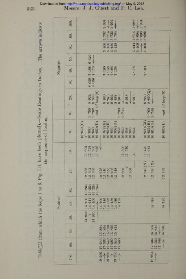
The sequence of the tests is shown by arrowheads on the diagram and by the figures in Table II. Starting at the point C on the zero stress line, a 50-lb. cycle was taken, and is shown marked No. 1 ; a 50-lb. half-cycle, marked No. 2, is then drawn. I t terminates at D, and is followed by cycles 3 (through E and terminating at F), 4 (to G), 5 (to M), and a half-cycle 6 (to L) taken to loads of +100 lb., with a number of small loops (such as GNHG), having a range of 20 lb., taken at various stages of the loading. For clearness of the figures, the loops 5 and 6 have been shifted vertically, the line A 'B ' being the new position of the line AB. Different types of broken lines are used to aid lucidity. The course of the observations is indicated by the arrowheads on the secondary curves and by the arrows in Table II. The width of the hysteresis loops increased with the range of loading. I t will be noticed, however, that, wherever on the range of stress the small included loops were taken, the widths for a definite range were nearly constant, but were rather greater near the zero load line than at the loaded parts of the main curve. The value of C, which has previously been decreasing, shows a very slight rise in the + 100-lb. cycles. The central pair of small loops are inclined to the main curve at the point where they branch from it, and, compared with AB, they give a slightly higher value for the rigidity. The unloading side of the other pair of small loops coincides with the unloading line of the main hysteresis loop.
In these tests there was no perceptible permanent creeping at any definite ‘ point, but a small amount apparently occurred towards the —100 lb. loading,
as shown by the curve 4 not coinciding exactly with 3. Except for this, within all these hysteresis loops the strain arrived at was definite and unaffected by time. The strain, however, at any or no load, depends upon the previous history. Thus at no load the specimen has been successively left with the strains indicated by the points CDEFGHKLM, and the
on May 9, 2018http://rspa.royalsocietypublishing.org/Downloaded from

'Torsional Hysteresis oj Steel. 321
cqisgi = anbuoispunod^i 02 - 9 1 1 ---- stH P*°l e
ScaJe
Rga
dirvqs
. I D
ivi.
on May 9, 2018http://rspa.royalsocietypublishing.org/Downloaded from
Tabl
e’ll
(fr
om w
hich
the
loo
ps 1
to
6, F
ig.
Ill,
hav
e be
en p
lotte
d).—
Scal
e H
eadi
ngs
in I
nche
s.
The
arro
ws
the
sequ
ence
of
load
ing.
322 Messrs. J. J. Guest and F. C. Lea.
£S
.3
©
too©£
©
OPh
oQO
o
d
d<M
8
occ
S'
oCD
d00
+S4-
QO I t P | QO I 00 |
- 1 2 1cq HP cq ^ « H (M C 1 IS J>CO CO 00 00
rft ^ QO <M H Oi 05 Ci cp cp 9CO 00 00 CO
O QO o 00CD <N iO H
to to to io-H 00$ 3 ><<
IQO CD 00 I>rH rH
I > I >
O 00 CD 00 05 Tp GO 00r —I rH rH r—l
I > | > Jt>
00
r —i
I> t>O CD
00 00
oTHP 00 ^O l 05 f t 05 X O * • OX X —•
O X (N X X oo i> cq cd h 05 00 C5 00 05X X X X X V
x cq cdCD 05 CD 00 00 00
cq cq cqrH rH rH
X O CD CD X t ' * H lO O ^ 00 Tft 00 rfl 00cq cq cq cq cqr —i rH rH rH rH
A..
^ rfi rficoto WIOcq cq cq cqOO X X 00r - i r -^ r ^ \ r - i
O rH O _ _O rH O . O -HV d d A H dT f -!fl
iH rH pH I i—i rH rH rH rH rH
o o cq <m o x, O ^ G 5 W X ( N
Ar< 9 7 ? 7*
05
2.rfirPOO^sq to (M t o hX 00 X X Xto l O ‘O to torH rH rH rH rH
CD CD O O O OH* CD Tfi CO rH CDtO t o t o t o t p tp
i> l> Ih l> inrH rH rH rH rH rH
cq05
ooo
g?s sX X
S'v—✓
y ©
^ 1 £3 'o HPCO
0593
COcq
rH
§ 3 I sX X X to to Y toH H 1 H
orH 9-
790
9-76
2 en
d o
9-79
0 9
-744
9-76
09-
748
end
o i
o
s §o o o o"H CD X CDZ D CD CD CD
O w O O OH Y H H H 10
-672
(E)
10 -
618(
F)
10 -6
66
10 -
608(
G)
10 -6
62
10 -6
40
10 -6
48
10 -6
38
10 6
44
10 -6
00 (M
) 10
-62
2(H
) 10
-61
0(G
)
10 -
660
(L)
orH
11 -
502
11 -
528
11 -
500
11 -
526
11 -5
00
11 -
510
11-4
70
11 -
482
HP X lw to H Ai p i p I p I
I> X> I
y - f t
tPcq
052 1
05
on May 9, 2018http://rspa.royalsocietypublishing.org/Downloaded from

Torsional Hysteresis o f Mild Steel. 323
material may be left at the stress and strain represented by any point within the main hysteresis loop without the manifestation of any time ■effect. The width of this part LM on the natural scale would show as one-twentieth of one scale division. The material may, from this point of view, be said to have slight permanent set, although there is no evidence of a time effect. The narrower the hysteresis loop over the range of stress considered, the more perfectly elastic the material may said to be.
The initial behaviour of the specimen upon any test then depends upon the previous history. Thus, for example, if the specimen be left in the state represented by the point M, the initial line will be along MNP ; but left in the state G, the initial line will be along GNP.
The effect of a slight overstrain of the material is shown in Fig. IV, which is again divided into two parts, and has the secondary figures exaggerated fifty times. Before the material was overstrained, the loops GB&B&X'WA were taken. The whole actual stress-strain curve (ABCDEFGHKEFGLMANPQR) is shown completely in the upper figure and contains loops of such magnitude as to be visible upon the normal scale. In this test the amount of permanent overstrain AG involved at zero stress is small compared with the strain which the material can sustain without time effects. In the loading, “ creep”—that is, slow increase of strain with time without alteration of load—first occurred at C, 120 lb. load (see Table III), and the main extension at D (150 lb.), while the strain continued to increase when the load was reduced to 140 lb. The loop EFGHKE shows no creep, but on continuing the curve to negative stress very distinct creep appears at L (upper figure) 60 lb. only. An exaggerated curve e/ghlcEfyi (lower figure) is drawn. This is not closed as the loops in Fig. I I were; also E /i^ x lies within efg,or the second unloading curve lies within the first. Secondary curves for later observations are also drawn. These show that after overstraining the material to the slight amount shown on the main curve, the internal condition of the material is upset, and, at any rate for some time, no actual straight line exists. At the load —60 lb. (point L) very slight creep occurs and the width rt(upper part of figure) of the hysteresis loop SY for + 60 lb. is nearly as wide as the width xt (lower part of figure) of the loop BW for the ±100 lb. cycle taken before the overstrain.
Similar curves for overstrain are given in Fig. Y, where a much larger amount of overstrain (here negative) is employed. The natural curve starts from A ( — 80 lb.) and passes through B to C (60 lb.), returning through D to A, and then through E back to F, and again on through G to H ( —145 lb.) where the large overstrain (HK) occurs. On the return, creep continued on the load being reduced to L ( — 130 1b.), and the following stress-strain
on May 9, 2018http://rspa.royalsocietypublishing.org/Downloaded from

324 Messrs. J. J. Guest and F. C. Lea.
^€S3J45\pvii 4 s j?d sqi^si - anfcuqi. cpMncy 3U|02 =*<U I - sqi -'Vu X jq p'ro-j-a ^u§ 3
\ %
on May 9, 2018http://rspa.royalsocietypublishing.org/Downloaded from

on May 9, 2018http://rspa.royalsocietypublishing.org/Downloaded from

Torsional Hysteresis o f Mild Steel.
■>** « n g g - - • ^ ~ X l y 3 5 ~ ~§ ,
325-
S 5? 2 2 § 3 §r S
on May 9, 2018http://rspa.royalsocietypublishing.org/Downloaded from

326 Messrs. J. J. Guest and F. C. Lea.
line is decidedly curved. Restoring creep began to occur at M ( — 601b.), and is well marked at no load N, and at the succeeding positive loads. After P ( + 60 lb.) the load was reduced, a loop PQRSP being formed. This and the succeeding loop are given in the secondary curve (exaggerated 25 times) pqrsi pi p 2 qn r2 s2 p2. Thus after an overstrain H K a little lessthan the preparatory elastic strain, the stability of the material is upset, creep occurring at + 60 lb. load, and the width of the loop is very considerable. In comparing the secondary loops of Fig. Y with those of Figs. I l l and IY it must be borne in mind that the magnification is only 25 as against 50 times.
j Effect of Rest on Overstrained Material.
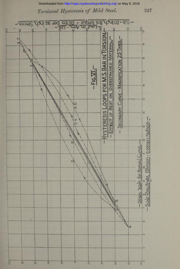
The effect of rest upon the material is shown in Fig. YI, in which again the secondary curves are exaggerated 25 times. Shortly after the overstrain of Fig. Y the loop, of which the secondary curve is ABCDEFG, Fig. YI, was taken, and this shows creep BC and EF at + 60 lb. loading. After 10 days' rest the specimen was re-tested and the secondary loop PQRSTY obtained; no creep occurred at — 80 lb. but a small amount ST occurred at + 80 lb. (so that Y does not join up to P). The width of the loop is reduced by this rest to less than half its previous amount. The loops are sufficiently wide to be shown on the natural stress-strain curves. The range of stress without creep is also considerably increased by this rest. The natural curve taken soon after the overstrain is shown in the full lines and that after rest in dotted lines, while the secondary curves are drawn by alternate dot and dash, and by dashes respectively.
Effect of Heating Overstrained Material.
The effect of boiling (at 100 °C.) upon the material is shown in Fig. YII, in which the exaggeration is again 25 times; 18 days after the previous overstraining, a test running between + 80 lb. gave the natural loop ABCD, with no creep, which is shown exaggerated at «BcD and is to be compared with the loop of Fig. YI taken after a shorter rest, 10 days. The test was continued— showing creep first at E (100 lb.)—in order to give the overstrain indicated by EFGG'HK (mainly at 140 lb.) when the load was reduced and a loop obtained as indicated by the line KLMNPQRSN. To keep this figure within bounds G has been transferred to G', whence the curve continues along G 'H 'K . In the loop NPQR8N creep occurs. During reduction of load from + 145 lb. creep occurred at L ( + 80 lb.) and continuously afterwards, at 60 lb., at 40 lb. and lower loadings. I t also persists in the following loops, as is clearly shown in the secondary figure NpgRwN. The specimen was then boiled in water for one hour and afterwards the loops (shown in the figure on
on May 9, 2018http://rspa.royalsocietypublishing.org/Downloaded from
Torsional Hysteresis o f Mild Steel. 32 7
sgi ?ci ■ anfauoi sqiXpMl 05 - q i I
on May 9, 2018http://rspa.royalsocietypublishing.org/Downloaded from

328 Messrs. J. J. Guest and F. C. Lea.- gg2s| s |ntuqyq|^02 »(g| - ggi XmyVio p -] —S__ f
t__11 o
o oGO O
on May 9, 2018http://rspa.royalsocietypublishing.org/Downloaded from

Torsional Hysteresis o f Mild Steel. 329
the right) between 60 and 80 lb. were taken for comparison with the loops «BcD« and N^RmN respectively. The loops obtained after boiling are very much narrower than those shown on the left of the figure, the width on the natural curve being covered by the width of the tapering line WS. Compared with the loop taken after 18 days’ rest, the width of the loop Wa^S^UW is about two-thirds that of aBcDa. The same loop is shown at BDAC in Fig. V III but the magnification here is 100. After taking the loop BDACB, Fig. VIII, the curve is continued along B'CDEF, showing creep at C and a considerable permanent set at EF. The unloading curve is FG-H and is followed by the loop HKLMK clearly seen on the natural curve. As before, return creep took place on the unloading curve, the condition of the material having been upset.
The specimen was then tempered, or as it is sometimes termed normalised, by being maintained at 330° C. for one hour in an electrically heated furnace. I t was then re-tested. In the natural curve obtained after heating all the observations are included in the width of the thickness of the taper line PX. The secondary curves PQRSVP of the loop for + 80 lb. loading is drawn for comparison with the loop ABCD, Fig. VIII, obtained after boiling, its width being about three-quarters of the latter. A second exaggerated loop TUVWT between + 40 lb. was then taken and the loading was afterwards continued as shown on the natural curve EX up to 140 lb. load, when a sudden yield XY occurred without signs of previous creep. The secondary figure for this loading is shown at WTRZXA'. A very small overstrain was permitted and the load gradually reversed, giving the line YB'C'D'E'. Creep occurred at D' ( — 110 lb.) and a yield at E' —140 lb. loading.
In all the above cases considerable yield occurred at about 140 lb. (+ or —) and sometimes yielding continued after the load had been reduced, but after heating at 330° C. no creep took place before the yield at 140 lb. After overstraining followed by rest or boiling at 100° C. creep occurred at less than 140 lb., so that normalising at the above temperature considerably extended the range in which the hysteresis loop is narrow and in which the material shows no sign of , creep.
It has not been thought necessary to include Tables from which all curves have been plotted, as the three given are quite representative of the results obtained during the tests. •
The particulars given in this paper are but a commencement of the researches it is proposed to carry out, but they clearly demonstrate the existence of a hysteresis loop at stresses considerably below the generally accepted elastic limits for mild steel, and they further show the beneficial effect of rest and of mild heat treatment.
on May 9, 2018http://rspa.royalsocietypublishing.org/Downloaded from

330 Messrs. J. J. Guest and F. C. Lea.
§
o-•gpVq>l -
o <~> ~o o o 1 oCvi O OQ <J3
O CM § S S § § S.
on May 9, 2018http://rspa.royalsocietypublishing.org/Downloaded from

331
One of the authors* has shown that the elastic limit in compression, as measured by an ordinary extensometer, of cold drawn steel tubes is very considerably raised by tempering at temperatures from 300° to 550° C.
During the severe treatment to which mild steel is subjected in cutting machinery the material is locally stressed so as to leave conditions of overstrain. After overstrain the material gradually, with time, acquires a more “ normal ” state, but a more perfect state is rapidly produced by slight heat treatment as above described. In several establishments manufacturing precision machinery the parts are allowed a considerable period of rest before the final operations are performed upon them, but one of the authors has used such heat treatment (temperature of boiling water and oils) for the past 15 years in the production of accurate machine details.
Another point that the experiments indicate is that the yield of a bar under torsion may be much more sudden than it is generally thought to be. After tempering the specimen at 330° C. the tendency to creep at less torsion loads than 140 lb. was nearly eliminated (entirely in the example of Fig. V III), but at 140 lb. a remarkably sudden yield occurred. The observation of this was very striking. The load was applied to the arm by small instalments and slowly. Upon reaching what proved to be the yield point load, for a short time no sign of yield occurred; the specimen then began to give way slowly and soon the rate of yielding became rapid and the bar twisted through a considerable range. The abruptness of yield appears, as is to be expected, to depend upon the uniformity of the material.
As the stress in a shaft under torsion reaches a maximum at the outer surface, the suddenness of this yield (after normalising) indicates that when the stress is close to the yield point the material is really unstable. The yielding of the outside thus starts the yield of the adjacent material which is not so highly stressed and which thus apparently yields at a lower stress than that at which the outside material yielded. If this were not so the yield of the outer material could only produce a small twist in the specimen as a whole.
Since fatigue effects depend upon the gradual increase of the width of the hysteresis loop with repetition, it would appear that boiling and tempering at comparatively low temperatures remove initial strains, and thus considerably increase the resistance of the steel to repetition stress. Hence parts to be subjected to such stresses, and materials, such as tubes, subjected to cold drawing can, with advantage, be normalised. One of the authorsf has for some years advocated the adoption of this treatment for such articles as crank shafts.
* ‘Recent Researches on Tubular Steel Struts,’+ ‘ Proc. Inst. Automobile Engineers,’ vol. 6 p. 365.
VOL. XCIII.— A. 2 C
Torsional Hysteresis o f Mild. .
on May 9, 2018http://rspa.royalsocietypublishing.org/Downloaded from

332 Torsional Hysteresis oj Mild Steel.
One more point is worthy of note, After overstrain it has been stated that negative creep occurred at diminishing loads, or, in other words, as the loads were decreased the twist of the bar diminished while the load was steady at a given amount. This is accounted for, if it be assumed that the stress near the surface of the bar is beyond the elastic limit, while nearer to the centre it is still within the elastic limit. Hollow specimens of various kinds of steel are to be tested as soon as opportunity offers.
The results obtained in these preliminary experiments are not such as to allow of definite conclusions being drawn as to the behaviour of material in general, but there seems to be no doubt that, for the mild steel used in these tests, the torsion stress-strain, curve for a rising or falling load does not obey Hooke’s Law, and that for a given range of torsion, well below that which produces a stress equal to what is generally considered the elastic limit of a mild steel, whether wholly positive, negative, or changing sign, a hysteresis loop is obtained and the elastic limit as at present defined would appear to be zero.
An examination of the curves given in the paper shows that for any given value of the torque, the slope of the stress-strain curve, and thus the modulus of rigidity, depends upon the way the stress is changing, and at any given stress, including zero stress, is not a constant quantity, but depends upon the previous history of the material.
The thanks of the authors are due to Mr. M. Parkes, Stud. Mem. Inst. C.E., for his skilled assistance in preparing the drawings from which the curves have been reproduced.
on May 9, 2018http://rspa.royalsocietypublishing.org/Downloaded from