Torsion
4
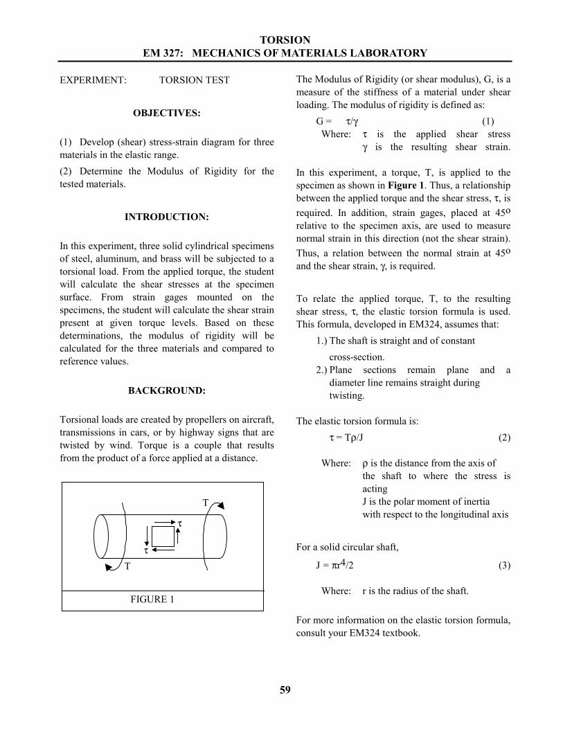
TORSION EM 327: MECHANICS OF MATERIALS LABORATORY 59 EXPERIMENT: TORSION TEST OBJECTIVES: (1) Develop (shear) stress-strain diagram for three materials in the elastic range. (2) Determine the Modulus of Rigidity for the tested materials. INTRODUCTION: In this experiment, three solid cylindrical specimens of steel, aluminum, and brass will be subjected to a torsional load. From the applied torque, the student will calculate the shear stresses at the specimen surface. From strain gages mounted on the specimens, the student will calculate the shear strain present at given torque levels. Based on these determinations, the modulus of rigidity will be calculated for the three materials and compared to reference values. BACKGROUND: Torsional loads are created by propellers on aircraft, transmissions in cars, or by highway signs that are twisted by wind. Torque is a couple that results from the product of a force applied at a distance. FIGURE 1 T T τ τ The Modulus of Rigidity (or shear modulus), G, is a measure of the stiffness of a material under shear loading. The modulus of rigidity is defined as: G = τ/γ (1) Where: τ is the applied shear stress γ is the resulting shear strain. In this experiment, a torque, T, is applied to the specimen as shown in Figure 1. Thus, a relationship between the applied torque and the shear stress, τ, is required. In addition, strain gages, placed at 45 o relative to the specimen axis, are used to measure normal strain in this direction (not the shear strain). Thus, a relation between the normal strain at 45 o and the shear strain, γ, is required. To relate the applied torque, T, to the resulting shear stress, τ, the elastic torsion formula is used. This formula, developed in EM324, assumes that: 1.) The shaft is straight and of constant cross-section. 2.) Plane sections remain plane and a diameter line remains straight during twisting. The elastic torsion formula is: τ = Tρ/J (2) Where: ρ is the distance from the axis of the shaft to where the stress is acting J is the polar moment of inertia with respect to the longitudinal axis For a solid circular shaft, J = πr 4 /2 (3) Where: r is the radius of the shaft. For more information on the elastic torsion formula, consult your EM324 textbook.
-
Upload
malak-w-ka -
Category
Documents
-
view
77 -
download
3
Transcript of Torsion
TORSIONEM 327: MECHANICS OF MATERIALS LABORATORY
59
EXPERIMENT: TORSION TEST
OBJECTIVES:
(1) Develop (shear) stress-strain diagram for threematerials in the elastic range.(2) Determine the Modulus of Rigidity for thetested materials.
INTRODUCTION:
In this experiment, three solid cylindrical specimensof steel, aluminum, and brass will be subjected to atorsional load. From the applied torque, the studentwill calculate the shear stresses at the specimensurface. From strain gages mounted on thespecimens, the student will calculate the shear strainpresent at given torque levels. Based on thesedeterminations, the modulus of rigidity will becalculated for the three materials and compared toreference values.
BACKGROUND:
Torsional loads are created by propellers on aircraft,transmissions in cars, or by highway signs that aretwisted by wind. Torque is a couple that resultsfrom the product of a force applied at a distance.
FIGURE 1
T
T
τ
τ
The Modulus of Rigidity (or shear modulus), G, is ameasure of the stiffness of a material under shearloading. The modulus of rigidity is defined as:
G = τ/γ (1) Where: τ is the applied shear stress
γ is the resulting shear strain.
In this experiment, a torque, T, is applied to thespecimen as shown in Figure 1. Thus, a relationshipbetween the applied torque and the shear stress, τ, isrequired. In addition, strain gages, placed at 45orelative to the specimen axis, are used to measurenormal strain in this direction (not the shear strain).Thus, a relation between the normal strain at 45oand the shear strain, γ, is required.
To relate the applied torque, T, to the resultingshear stress, τ, the elastic torsion formula is used.This formula, developed in EM324, assumes that:
1.) The shaft is straight and of constant cross-section.
2.) Plane sections remain plane and adiameter line remains straight during twisting.
The elastic torsion formula is:τ = Tρ/J (2)
Where: ρ is the distance from the axis of the shaft to where the stress isactingJ is the polar moment of inertia with respect to the longitudinal axis
For a solid circular shaft,
J = πr4/2 (3)
Where: r is the radius of the shaft.
For more information on the elastic torsion formula,consult your EM324 textbook.

TORSIONEM 327: MECHANICS OF MATERIALS LABORATORY
60
Next, a relationship between the normal strains andthe shearing strain is required. This is a result of theinability of strain gages to measure shear strains.Strain gages can only measure normal strains fromgages in the proper orientations.
Since for pure torsion, the maximum tensile stressand the maximum compressive are equal inmagnitude to the shear stress, there will be nonormal stress on either the longitudinal or transverseplane on which the maximum shearing stress acts.Likewise, there is no shearing stress on the planes at45 degrees from the maximum normal stresses.Figure 2 illustrates this concept.
FIGURE 2
T
T
τ
τσmax
=
For the case where normal strain εx and εy, and theshear strain, γxy, are known, the normal strain, εθ,along a line oriented with respect to the X-axis byand angle θ (Figure 3) is:
( ) ( )θγ
θεεεε
εθ 2sin2
2cos22
xyyxyx +−
++
= (4)
For the case where θ = 45o:cos2θ = 0, and sin2θ = 1
Therefore, the relationship becomes:
2245xyyx γεε
ε ++
= (5)
Solving for γxy:
γxy = 2ε45 - (εx+εy ) (6)
Thus, we have developed a relation between theshear strain, γxy, and the normal strains.
For the case of pure torsion, a pure shear stress stateshould exist such that σx = σy = 0, and thereforeεx = εy = 0 for this case,
γxy = 2ε45 (7)Similarly,
γxy = -2ε−45(8)
Therefore, the shear strain, γxy, may be determinedfrom either ε45, ε−45 , or as a combination of thetwo strain readings using equations (7) and (8)
γxy = ε45 - ε−45(9)
This result may also be obtained using the methodof Mohr's circle, a topic presented later in EM324.
A three-strain gage rosette has been bonded ontoeach of the three specimens. The rosette is orientedsuch that the three gages measure strains at 00, -450, and +450 with respect to the longitudinal axisof the specimen. Thus by using equation (6), theshear strain may be determined. If the strains in the00 and 900 directions are zero (as is expected forthe case of pure torsion), then equation (7) may beused.
MATERIALS TO BE TESTED:Steel (SAE 1020)Aluminum (6061-T6)Brass
A 1-inch diameter specimen of each material hasbeen machined and instrumented for testing.

TORSIONEM 327: MECHANICS OF MATERIALS LABORATORY
61
FIGURE 3
x
y
ε45
ε−45
ε0
θ = 45ο
θ = −45ο
EQUIPMENT TO BE USED:Riehle torsion testing machineStrain indicatorSwitch and balance unit
SAFETY:Be careful to avoid pinching fingers in grips duringinstallation of parts.
PROCEDURE:
PRELIMINARY CALCULATIONS:Preliminary calculations are not required.
SPECIMEN PREPARATION:The diameters of each sample must be measured.Care should be taken to avoid damage to straingages mounted on each specimen.
TESTING PROCEDURES:1.) Place specimen in grips.2.) Zero the strain indicator as described in the
equipment section.
3.) Turn crank clockwise to apply load.4.) Take torque and strain measurements at
increments of approximately 200 in-lb up to2000 in-lb.
5.) Unload specimen and remove from grips.6.) Repeat procedure for each specimen.7.) Turn strain indicator power ‘OFF’.
REPORT:
The report outline found in Appendix A should beused.
REPORT REQUIREMENTS:(1) Convert torque readings to stress using the
elastic torsion formula. Tabulate torque, strain,and stress data. You will add more data to thistable as you complete the report requirements.
(2) A shear stress (y-axis) vs. shear strain (x-axis)curve is to be produced for each specimentested. Plot the data from each of the specimenson one graph using proper plotting procedures.This may be done by hand or using a computer.Fit a straight line through each set of data. Useeither linear regression or an eyeball fit to findthe slope of each fitted line. The slope of eachline is the Modulus of Rigidity for eachmaterial. Add these results to your table from(1).
(3) Recall your results from the Poisson’s Ratiotest you conducted previously. Using theModulus of Elasticity and Poisson’s Ratio youfound for each material in that experimentpredict a Modulus of Rigidity for eachmaterial.
(4) Calculate the %error between the measuredand reference values and include thisinformation in your table. Also calculate the%error between the Modulus of Rigiditycalculation based on the Poisson’s Ratio resultsand those measured in this lab using the resultsfrom this lab as the reference.
(5) Summarize, in words, the results of the testing.Comment on the correlation betweenexperiment and reference values and discuss
TORSIONEM 327: MECHANICS OF MATERIALS LABORATORY
62
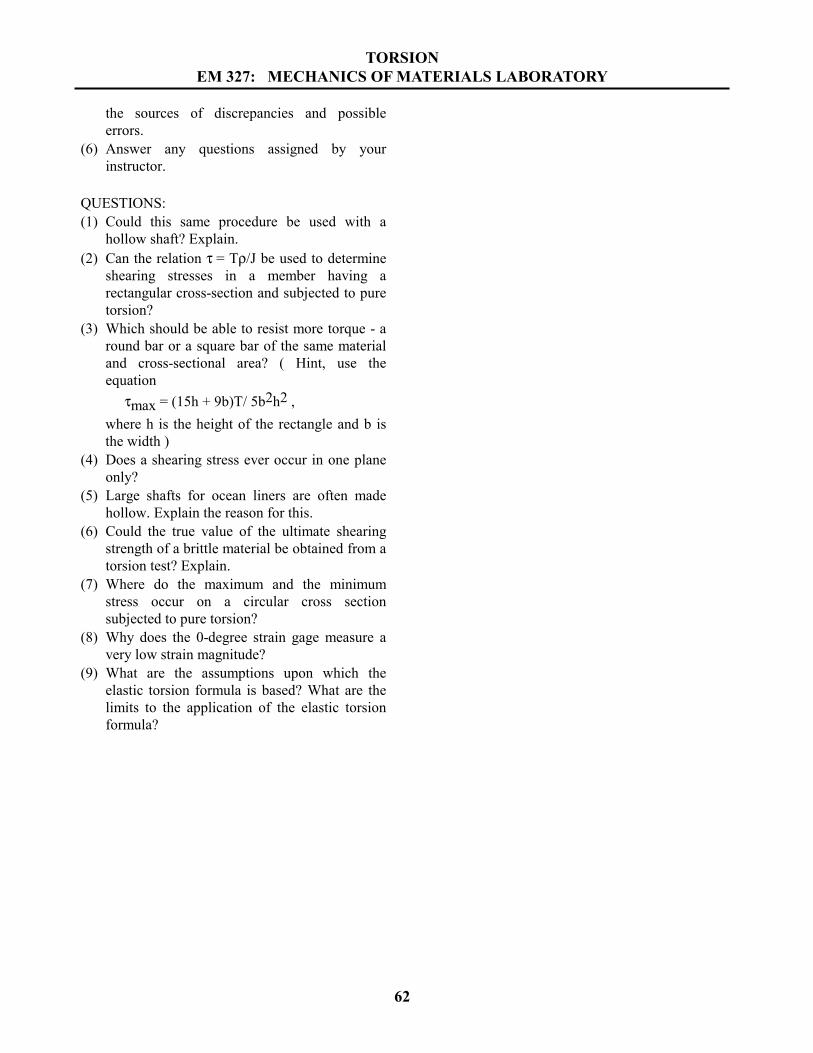
the sources of discrepancies and possibleerrors.
(6) Answer any questions assigned by yourinstructor.
QUESTIONS:(1) Could this same procedure be used with a
hollow shaft? Explain.(2) Can the relation τ = Tρ/J be used to determine
shearing stresses in a member having arectangular cross-section and subjected to puretorsion?
(3) Which should be able to resist more torque - around bar or a square bar of the same materialand cross-sectional area? ( Hint, use theequation
τmax = (15h + 9b)T/ 5b2h2 ,where h is the height of the rectangle and b isthe width )
(4) Does a shearing stress ever occur in one planeonly?
(5) Large shafts for ocean liners are often madehollow. Explain the reason for this.
(6) Could the true value of the ultimate shearingstrength of a brittle material be obtained from atorsion test? Explain.
(7) Where do the maximum and the minimumstress occur on a circular cross sectionsubjected to pure torsion?
(8) Why does the 0-degree strain gage measure avery low strain magnitude?
(9) What are the assumptions upon which theelastic torsion formula is based? What are thelimits to the application of the elastic torsionformula?