TORQUE user guide - Bolt Science user guide.pdf · TORQUE is a program which is designed to assist...
23
User Guide TORQUE Program Software for the Torque Tightening of Threaded Fasteners TORQUE is produced by Bolt Science Limited Bolt Science provides analytical solutions to bolting problems http://www.boltscience.com
Transcript of TORQUE user guide - Bolt Science user guide.pdf · TORQUE is a program which is designed to assist...

User Guide
TORQUE Program
Software for the Torque Tightening of Threaded Fasteners
TORQUE is produced by Bolt Science Limited Bolt Science provides analytical solutions to bolting problems
http://www.boltscience.com

COPYRIGHTS
Copyright © 1996 - 2018 by Bolt Science Limited. All rights reserved. No part of this publication may be transmitted, transcribed, reproduced, stored in any retrieval system or translated into any language or computer language in any form or by any means, mechanical, electronic, magnetic, optical, chemical, manual or otherwise, without prior written consent from the Legal Department at Bolt Science Limited, 16 Rotherwick Avenue, Chorley, Lancashire PR7 2PY, United Kingdom.
The software described in this User Guide is provided under license and may be used or copied only in accordance with the terms of such licence. The details of the license are shown when you first install the software. Details of the license, if required, are available from Bolt Science.
Important Notice
Bolt Science provides this publication "as is" without any warranty of any kind, either express or implied, including but not limited to the implied warranties of merchantability or fitness for a particular purpose. Some jurisdictions do not allow a disclaimer of express or implied warranties in certain transactions; therefore, this statement may not apply to you. Bolt Science reserves the right to revise this publication and to make changes from time to time in the content hereof without obligation of Bolt Science to notify any person of such revision or changes.
Trademark References
TORQUE is a trademark of Bolt Science Limited in the United Kingdom and/or other countries.
All other products mentioned herein may be trademarks of their respective holders and are hereby recognised.
Bolt Science Limited 16 Rotherwick Avenue Chorley Lancashire PR7 2PY United Kingdom
URL: www.boltscience.com Email: [email protected]

User Guide TORQUE Program Contents i
Contents
Installing TORQUE 1
Introduction .............................................................................................................................................. 1 System Requirements ............................................................................................................................... 1 Installing TORQUE .................................................................................................................................. 1
Introduction 2
About TORQUE ....................................................................................................................................... 2
Initial Bolt Size Estimate 3
Introduction .............................................................................................................................................. 3 Entering of Values .................................................................................................................................... 3 Bolt Size Estimate Results ....................................................................................................................... 4
Torque Analysis 5
Introduction .............................................................................................................................................. 5 Background to a Torque Analysis ............................................................................................................ 6 Data Entry Form ....................................................................................................................................... 7 Bolt Details ............................................................................................................................................... 7
Fastener Thread Details ............................................................................................................. 7 Outer Bearing Diameter of the Fastener .................................................................................... 7 Countersunk Head Screws ......................................................................................................... 7 Inner Bearing Diameter of the Fastener ..................................................................................... 8 Fastener Clearance Hole ............................................................................................................ 8 Fastener Strength Grade Selection ............................................................................................. 8
Bolt Tightening Condition ........................................................................................................................ 9 Yield Factor Method .................................................................................................................. 9 Defining a Tightening Torque .................................................................................................. 10 Defining a Bolt Preload ............................................................................................................ 10
Friction Coefficient Databases ............................................................................................................... 10 Scatter in the friction value ...................................................................................................... 10
Prevailing Torque Value ........................................................................................................................ 11 Prevailing Torque Variation ..................................................................................................... 11
Stresses in the fastener ........................................................................................................................... 11 Von-Mises Failure Criterion .................................................................................................... 11
Considerations on Torque Tightening .................................................................................................... 12 Washers .................................................................................................................................... 12 Tolerance class of fasteners ..................................................................................................... 12 Re-use of plated fasteners ........................................................................................................ 12
The TORQUE Databases 13
Introduction ............................................................................................................................................ 13 Thread Friction Database ....................................................................................................................... 13 Nut Face Friction Database .................................................................................................................... 14 Material Properties Databases ................................................................................................................ 14 Thread Databases ................................................................................................................................... 15

User Guide TORQUE Program Contents ii
Glossary of Terms 17

User Guide TORQUE Program Installing TORQUE 1
Installing TORQUE
Introduction This chapter provides information on installing and starting TORQUE. It presents the following topics:
System Requirements
Installing TORQUE
System Requirements To install and run TORQUE, your Windows compatible PC must be equipped with the following:
Microsoft Windows 7 or 10 .
100 MB of free space on your hard drive.
SVGA monitor with at least 800 x 600 pixel resolution.
Installing TORQUE The TORQUE installation program provides easy step by step instructions on every screen.
Before you install TORQUE
1. Close all other programs.
2. If you are first installing TORQUE, log onto your computer with administrator privileges.
To install TORQUE from a CD
1. Insert the CD into your CD-ROM drive. The installation program should start automatically. If it does not, follow the instructions located on the sleeve of the CD.
2. Follow the instructions on each screen to install the software.

User Guide TORQUE Program Introduction 2
Introduction
About TORQUE TORQUE is a program which is designed to assist the Engineer in the solution of problems related to the torque tightening of threaded fasteners.
TORQUE is a computer program that provides a means of determining the correct tightening torque and the resulting anticipated clamp force for a threaded fastener. The program accounts for both the tensile stress, due to elongation of the fastener, and torsional stress, due to the applied torque. It will account for both the frictional effects in the thread and between the nut face and clamped surface. Account can also be made for the effects of a reduced shank diameter (smaller than the thread size) and a prevailing torque. The program has also the facility to allow the tightening torque to be calculated from a specified clamp force - or vice versa.
Following the guidelines presented in this manual in the use of the program, it is possible to allow, at the design stage, for the anticipated variation in the fasteners clamp force as a result of frictional scatter. Also the tightening torque can be established which will ensure that a torque is not specified which would result in the fastener being over-stressed.
Engineering programs such as TORQUE are valuable design aids, but they should be used with caution. They need engineering judgement and experience to allow the results to be properly interpreted. Due to the inherent variations in the coefficient of friction, both in the threads and between the nut face and clamped surface, there is no single "correct" tightening torque for all circumstances. A range of values can be determined however given the anticipated frictional scatter. The amount of frictional scatter, which the engineer allows for when determining the clamp force and tightening torque, should be based upon experimental results taken from the application. The guideline values presented in the program are based upon published research results. When the data permits, lower bound values are presented to safeguard against the fastener being over tightened. Lower the value of the coefficient of friction, lower will be the tightening torque.
The program has a database of standard values built into it to allow the easy selection of the most appropriate fastener. The program allows selection of metric fine as well as metric coarse threads; the user can enter non-standard fastener sizes as well. The program will also allow the use of imperial units (lbs. and inches) and the unified thread form.

User Guide TORQUE Program Initial Bolt Size Estimate 3
Initial Bolt Size Estimate
Introduction An Engineer is frequently faced with the problem of deciding what size of fastener is needed for a particular application and loading. The purpose of the initial bolt size estimate facility is to provide a prediction of the size of bolt required to sustain a particular loading.
This analysis option is selected by clicking Initial Bolt Size Estimate under the Analysis main menu entry. The form that appears is shown below:
Entering of Values To allow an estimate of the required bolt size to be computed, it is first necessary to define the loads acting on the joint. By clicking on the appropriate button, additional information can be provided on the input values.
In order to estimate the bolt size, certain approximations have had to be made. Whether or not these or valid depends upon the particular application. In most situations, a bolt diameter slightly larger than is necessary would be provided. However, the size should be checked by defining specific values for your application on the data entry form.

User Guide TORQUE Program Initial Bolt Size Estimate 4
Additional information and clarification about the values being requested on the form can be provided by clicking on the button opposite the edit boxes at the right. Once the data has been entered, clicking the OK button on the form allows the program to check for valid values and to display the results on the main form.
Bolt Size Estimate Results After all the relevant data has been entered, the program will compute a bolt size estimate once the Ok button on the form is clicked. In general, the program will provide approximate bolt sizing based upon the stress area computed for a particular strength grade or property class of the bolt. Size options are provided for both fine and coarse threads.
Usually the bolt size estimate facility is used to assist the engineer in his/her judgement of the thread size needed. A full analysis should be completed to ensure that the approximation is correct and that other criteria, such as fatigue strength and bearing stress requirements, are met.

User Guide TORQUE Program Torque Analysis 5
Torque Analysis
Introduction The Torque Analysis option provides a means of determining the correct tightening torque and the resulting anticipated clamp force for a threaded fastener. The program accounts for both the tensile stress, due to elongation of the fastener, and torsional stress, due to the applied torque. It will account for both the frictional effects in the thread and between the nut face and clamped surface. Account can also be made for the effects of a reduced shank diameter (smaller than the thread size) and a prevailing torque. The program has also the facility to allow the tightening torque to be calculated from a specified clamp force - or vice versa.
The importance of ensuring that fasteners securing an assembly maintain a minimum clamp load is often critical in ensuring that the assembly performs satisfactory in service. When fasteners fail to maintain a minimum required clamp load, it is frequently other elements in the assembly that apparently fail. Examples of this are when gaskets leak because of insufficient clamp load to maintain a seal, or when brackets fail because of the load transfer that can occur when bolts come loose. The assumptions made by a Design Engineer regarding the magnitude of a fastener's clamp load is an important consideration in ensuring that an assembly will perform satisfactory throughout its design life. The importance of ensuring the fastener clamp load is adequate at the design stage is frequently underestimated.
The torque control method of tightening is the most popular way of ensuring that a fastener complies with an engineering specification. Most engineers recognise that the method is susceptible to inaccuracy. This being primarily due to variations in the coefficient of friction present in the threads and between the nut and joint surface.
At the design stage it is often necessary to be able to determine the clamp force which will be provided by a fastener. Frequently, because of the lack of any better information, the clamp force is determined by assuming that a certain value will be achieved. The value assumed is frequently a certain percentage of the fasteners proof load (normally a value of 75% is used). This program determines both the tensile and torsional stresses generated by the tightening process.
To facilitate ease of data entry, the program uses a number of databases containing information that is needed for an analysis. Specifically, the thread database contains thread dimensional data, the material database - information on bolt material specifications and thread and nut face friction databases for friction coefficients.

User Guide TORQUE Program Torque Analysis 6
Background to a Torque Analysis In general, the tightening torque can be considered to consist of four separate parts:
The torque needed to extend the fastener.
The torque needed to overcome thread friction
The torque needed to overcome nut face friction.
The prevailing torque, if present.
The torque needed to extend the fastener is that which generates the preload, typically it represents between 5% and 10% of the total tightening torque that is needed to be applied.
The torque needed to overcome thread friction is present because of the 'stickiness' of the internal and external thread surfaces. This torque does not increase the preload but does have the effect of creating a torsional shear stress in the threads. The thread friction torque is directly related to the value of the thread coefficient of friction. It is determined by the finish applied and the state of lubrication. Typically it represents about 40% of the total applied torque.
The torque needed to overcome nut face or under bolt head friction (depending on whether the nut or the bolt is rotated) represents typically 50% of the total applied torque. Again it is directly related to the friction coefficient under the bolt head or nut face that in turn depends upon the finish applied to the bolt, the lubrication condition and the joint material and surface condition.
The prevailing torque is the torque required to run a nut (or bolt) down a thread on certain types of fasteners that are designed to resist vibration loosening. This prevailing torque can be provided by an insert in the nut/bolt thread, by using nuts that have their threads locally distorted or by using micro-encapsulated adhesive applied to the threads. The effect of this torque is to increase the torsional stress acting in the threads.
The torsional stress, due to the applied torque, will be imposed upon the tensile stress due to the extension of the fastener. Failure of the fastener can be considered to occur when the combined effects of the tensile and torsional stresses reach a critical value. The Von-Mises distortion energy failure criterion is used by the program to determine an equivalent stress for the combined effects of torsional and tensile stresses.

User Guide TORQUE Program Torque Analysis 7
Data Entry Form The Data Entry Form consists of a number of pages that the user enters data into. To move between each page, the user should click the tabs at the top of the form marked Remarks, Bolt Details or Tightening Details.
Bolt Details It is necessary to define to the program the specific details of the thread hole and bolt head or nut face details together with the material that is to be used to allow the appropriate tightening torque to be established.
Details of the bolt diameter and thread pitch can be entered directly into the program. Alternatively the user can select the fastener thread size from a database of standard threads by clicking on the appropriate button. The database also presents a range of other information about the thread. The program requires that only the fastener diameter and pitch be entered. The description of the thread is optional.
The thread size database form also displays additional information about the thread size, such as thread tolerances.
The program also enters standard data that relates to a standard fastener diameter into other entry boxes (such as the clearance hole). The user can change all these values. The user should check that any default value is appropriate for the specific application.
If a standard thread is being used then the program will automatically fill in standard values for the user if a thread from the database has been selected. If the user wishes to over-write any of these values, the program will allow it. For example if a reduced shank fastener is being used then the user can enter the appropriate diameter. The majority of fasteners have the shank diameter equal to the outside thread diameter. However some fasteners have the shank diameter reduced so that its resilience is improved. When the shank diameter is reduced to below the diameter of the stress area (the mean of the root and pitch diameters), then that area becomes the critical section as regards potential failure during tightening. The program will default to the outside diameter of the thread; this can be changed by the user typing in a smaller diameter if a reduced shank fastener is being used.
The program defaults are for standard thread forms such as the metric or unified threads. These threads have a flank angle of 60 degrees. Other, now redundant thread forms, have differing flank angles.
In this data entry box, the user should enter the minimum value of the outside diameter of the nut or bolt. There are also a number of check boxes that allow the selection of the fastener head type to be made, the Standard Hexagon Head check box acts as the default.
The program will enter a standard value if a standard diameter had been previously entered. Clicking on the Socket Head Cap Screw check box would select an appropriate diameter for this type of screw. By clicking the 'Other' check box, the user can enter his/her own value.
The user should check that any default value is appropriate for the specific application being considered. The standard values used by the program may not be appropriate or correct for the user's application.
If the fastener being used is a countersunk headed screw, then when the check box is clicked with this title, another window opens giving details about this head type. The effect of the countersunk head is to increase the frictional resistance because of the wedging action of the head. Subsequently, other factors being equal, a higher tightening torque is needed
Fastener Thread Details
Outer Bearing Diameter of the Fastener
Countersunk Head Screws

User Guide TORQUE Program Torque Analysis 8
with a countersunk head socket screw then with a standard head. If a nut is used (and the nut rather than the screw is tightened) than please enter details of the nut on the main form rather then using this form. (Details of the part that is being rotated should be entered is the appropriate torque/preload value is to be computed.)
The default head angle for the screw quoted by the program is the minimum angle for a standard countersunk head socket screw. The value can be changed to accomodate special designs. Countersunk head screws are usually used only in moderately loaded applications, they are not usually used in critical fastening applications.
The program, in the report listing will detail the effective friction diameter that the program has calculated and has used in the torque analysis. For countersunk headed screws, the effective friction diameter is generally larger than the actual head diameter. This is because the friction diameter has been adjusted to allow for the wedging effect of the head style.
In this box, the user should enter the minimum value of the inner diameter of the nut or bolt. In many applications, this is the same as the clearance hole, but not in all cases. The program's default is that the inner-bearing diameter is equal to the clearance hole diameter. By clicking the 'User defined Inner Bearing Diameter' check box, the user can enter his/her own value.
Again, the user should check that any default value is appropriate for the specific application.
In this box details of the diameter of the fastener clearance hole are entered. There are four check boxes in this section, with the 'Fine' button acting as default.
By clicking on the appropriate button the clearance hole related to the particular hole series defined in ISO 273:1979 (Fasteners - Clearance holes for bolts and screws) is selected if a standard bolt diameter has been previously selected. If the user wants to select a specific value not within this standard, by clicking on the 'User defined' check box the data entry box can be edited.
The majority of joints incorporating bolts in general mechanical engineering applications have clearance holes (that is, the hole diameter is larger than the bolt diameter). Clearance holes improve the ease in which the product can be assembled and, by allowing a reduction in the tolerances required, reduce manufacturing costs. The program will allow the user to select the appropriate clearance hole based upon ISO 273. Alternatively, the user can enter the appropriate size if required. When the clearance hole is only slightly larger than the bolt diameter, care should be taken to ensure that interference is avoided between the edge of the hole and the underhead fillet of the bolt. A chamfer may be necessary. This is to avoid high-localised stresses that could lead to excessive preload loss from embedding.
Details of the yield strength of the fastener is required by the program. Information can be directly entered into the program or alternatively, the user can select an appropriate material by accessing the bolt material database that contains hundreds of bolt material specifications.
Property Class is the term used in the ISO metric fastener standards for strength grade. This terminology has been used by the various national standards when they adopted the ISO. The designation system used for the metric property class system is significant, in that it denotes minimum yield and tensile properties for the fastener. The designation system for bolts consists of two parts:
Inner Bearing Diameter of the Fastener
Fastener Clearance Hole
Fastener Strength Grade Selection

User Guide TORQUE Program Torque Analysis 9
The first numeral of a two-digit symbol or the first two numerals of a three-digit symbol approximate 1/100 of the nominal tensile strength in N/mm² (or MPa).
The last numeral approximates 1/10 of the ratio expressed as a percentage between nominal yield stress (or the stress at the 0.2% permanent set limit) and nominal tensile stress.
The minimum tensile and yield strengths (or the 0.2% permanent set limit) are equal to or greater than, the nominal values. Hence a fastener with a property class of 8.8 has a minimum tensile strength of 800 N/mm² (or MPa) and a yield stress of 0.8x800=640 N/mm². The designation system for metric nuts is a single or double digit symbol. The numerals approximate 1/100 of the minimum tensile strength of the nut in N/mm².
For example, a nut of property class 8 has a minimum tensile strength of 800 N/mm². A bolt or screw of a particular property class should be assembled with the equivalent or higher property class of nut to ensure that thread stripping does not occur.
Designers can easily specify the highest strength grade for critical applications. However, they may do this without a full assessment of the associated risks. Research and experience has indicated that fasteners of hardness exceeding C39 on the Rockwell scale (such as grade 12.9 fasteners) have a high susceptibility to stress embrittlement. The higher the hardness of the fastener (which is directly related to the strength of the fastener for steel) the more critical becomes the choice of material and heat treatment.
Fasteners of property class 12.9 require careful control of the heat treatment operation and cautious monitoring of surface defects and the surface hardness. In addition, they are also more prone to stress corrosion cracking of non-plated as well as electro-plated finished fasteners.
Bolt Tightening Condition The program allows for four ways in which the bolt preload can be defined, these are:
1. Yield Factor Method
2. Defining a Tightening Torque
3. Defining a bolt preload
Considering each in turn.
The yield factor method requires the percentage of the yield strength that is wished to be used, to be specified. This is the normal way that the assembly tightening torque is determined and what preload this will result in. The program defaults to this method. The program defaults to 90% (a 0.9 yield factor) utilisation of the yield strength of the bolt material from the combined effects of tension and torsion. A yield factor of one would result in yield occurring of the bolt material. By double clicking on the Yield Factor button, the 0.9 yield factor default can be changed by the user. A 0.9 yield factor would result in approximately 75% of the yield being utilised in direct tension - dependent upon the friction conditions. The yield factor method is more consistent than assuming a proportion of yield in tension is to be used. This is because it allows torsional stresses to be included (such stresses vary with the friction value in the thread) in the determination of the appropriate value of the tightening torque. The 10% of yield strength remaining in the bolt material (when the default 0.9 yield factor is used) is usually sufficient to allow the additional stresses imposed on the bolt by external forces to be sustained.
Yield Factor Method

User Guide TORQUE Program Torque Analysis 10
By clicking on the button marked 'Tightening Torque', the user can enter an assembly tightening torque that the program will use to determine the bolt preload after considering the friction conditions specified. The bolt details need to be entered prior to using this form. This is to allow the program to determine what the tightening torque would be which would result in yield of the bolt material occurring. This is displayed on the form to assist the user in entering an appropriate value for the torque. The program will not allow a torque to be entered that would exceed the bolt's yield strength. The value suggested in the data entry box is that based upon a yield factor of 0.9 being used. Any torque value greater than zero, but below that which would cause yield, can be entered.
By clicking on the button marked 'Assembly Preload', the user can enter a bolt preload value that the program will use. The bolt details need to be entered prior to using this form. This is to allow the program to determine what the preload would be that would result in yield of the bolt material occurring. This is displayed on the form to assist the user in entering an appropriate value for the preload. The program will not allow a preload value to be entered that would exceed the bolt's yield strength. The value suggested in the data entry box is that based upon a yield factor of 0.9 being used. Any preload value greater than zero, but below that which would cause yield, can be entered.
Friction Coefficient Databases Major influences on determining the appropriate tightening torque are the friction coefficients in the thread and under the face of the nut or bolt head. Establishing the value of these friction coefficients for particular material and finish conditions can be problematical unless test data is at hand.
The databases that are supplied with the program contain the results of tests conducted for that finish condition. The database lists the source of the information for reference purposes. Three values for the friction coefficients are listed; the minimum, mean and maximum values for that particular friction condition. One of the major problems in using torque control is the variability in the friction values that directly influences the resulting preload for a given applied torque value. Normally a minimum value of the friction coefficient should be selected since this gives the lowest tightening torque and hence ensures that the fastener will not be overtightened. The user can use the mean or maximum friction value but it should be borne in mind that this will lead to a higher tightening torque that may result in the fastener being over tightened.
Many test results or information from lubricant and finish suppliers list only the mean value of the friction coefficient. The database consists, in part, of test results that listed only the mean value of friction. Some tests define the minimum and maximum values, whenever the information is available the program lists the friction values based upon minimum and maximum values being 3 standard deviations away from the mean. In cases when only the test reported the mean result, to establish the minimum and maximum values the following equation was used:
Maximum Friction Value = 1.5 x Minimum Friction Value
The 1.5 factor was established based upon an analysis of the scatter associated with over 60 sets of tests conducted on different finish and lubrication conditions. The database states whether the minimum and maximum values were calculated from the mean or determined by testing.
Defining a Tightening Torque
Defining a Bolt Preload
Scatter in the friction value

User Guide TORQUE Program Torque Analysis 11
Prevailing Torque Value The prevailing torque is the torque required to run a nut (or bolt) down a thread on certain types of fasteners that are designed to resist vibration loosening. This prevailing torque can be provided by an insert in the nut/bolt thread, by using nuts that have their threads locally distorted or by using micro-encapsulated adhesive applied to the threads.
If a bolt diameter has been entered into the program, by clicking on the appropriate selection, the program will enter a lower bound value for the prevailing torque by default – check whether this is applicable to your application.
The characteristics of the majority of prevailing torque fasteners (nylon/polyester patch and distorted head types) are such that the magnitude of the prevailing torque reduces as the number of installations and removals increase. Typically the maximum prevailing torque listed is that for the first assembly. Standards such as ISO 23201 typically do not list a minimum value of prevailing torque but does list the fifth removal torque. The fifth removal torque, when other information is not available is taken as the minimum value of the prevailing torque. The difference between the minimum and maximum prevailing torque can be quite substantial.
Bolts which have a prevailing torque are frequently used where there exists a risk of vibration loosening. The prevailing torque counteracts the off torque which can be present when the bolt is subjected to vibratory loading. During the tightening process, this prevailing torque has the effect of increasing the torsional stress in the shank of the bolt. For the same state of combined stress in the bolt, the higher the torsional stress in the bolt, the lower will be the resulting preload. For the same frictional conditions, the total tightening torque required to tighten the bolt so that so that a specified combined stress exists in the shank of the bolt, does not significantly increase with increasing prevailing torque. However the preload in the bolt can be significantly reduced.
The use of threadlocking adhesives, such as structural cyanoacrylate and anaerobic compounds, results in the bolt/nut exhibiting a prevailing torque characteristic. This effect also occurs with adhesive contained within micro-beads applied to the threads. The magnitude of the prevailing torque is generally less than with proprietary prevailing torque fasteners, however the use of threadlocking compounds does still affect the tightening torque specification and the resulting preload.
The user can enter his/her own value of prevailing torque into the program. By default, the minimum value is used but the maximum can easily be selected. These values should only be used when more specific information is not available from the fastener manufacturer or from test work.
Stresses in the fastenerWhen the fastener is tightened the shank sustains a direct stress, due to the elongation strain, together with a torsional stress, due to the torque acting on the threads. Values for both the tensile and torsional stresses in the thread (or plain shank if a reduced shank fastener is being used) are presented in the results.
To determine an equivalent stress to allow a comparison to be directly made to a percentage of the yield strength, the program uses the Von-Mises failure criterion. The Von-Mises (sometimes called the theory of constant energy of distortion) theory is the most widely accepted for the elastic failure of ductile materials and agrees closely to experimental evidence. The program
1 ISO 2320 Prevailing torque type steel hexagon nuts
Prevailing Torque Variation
Von-Mises Failure Criterion

User Guide TORQUE Program Torque Analysis 12
computes the direct and torsional stresses and combines these two values together using the Von Mises criteria to establish an equivalent stress that can be compared to the yield strength of the material or a percentage thereof.
The tensile force in the fastener shank is determined by multiplying the stress area (or shank area when applicable) by the tensile stress. The 90% utilisation of the yield strength of the fastener is used as default by the program to allow some reserve on strength to allow for the application of the working load. If the working load is applied to the fastener and the yield strength is exceeded, then upon release of this load a tension loss in the fastener will result which can cause loosening and/or joint failure. Generally, the fastener sustains a small proportion of the working load, the majority is sustained by a reduction in the clamp force in the joint interface.
There is widespread misunderstanding by Engineers on the load transfer mechanism involved when a bolted joint sustains an axially applied force. Consider the case of a single bolt supporting a bracket. Before a nut is tightened, the bolt would sustain the entire working load. However, once the bolt is tightened, so that a tensile force (preload) is present within the bolt, clamping the bracket to the support, the bolt would sustain an applied force less than the working load. Typically, the bolt sustains less than 20% of the working load.
From a Designer's viewpoint, this illustrates one of the special features of a bolted joint in comparison to other components. The load-carrying mechanism of the joint is dependent upon the assembly operation itself.
Considerations on Torque Tightening If loose fitting washers are used, inaccuracies can occur in the torque-tension relationship. The washer seating eccentrically relative to the bolt axis brings this about. The resulting high stress on one side of nut-washer interface, brought about by this eccentricity, can result in the deterioration of the bearing surface. This increases the surface friction as tightening progresses. Increasing friction can cause the relative motion to change to the other interface (that is, the washer to the joint). This changing of the interface can affect the bearing face torque by as much as 15%. To eliminate this potential problem give consideration to either using close fitting washers, or, if feasible to the use of flange type fasteners.
Fasteners are generally made to comply with standard tolerance classes. Variations in the effective diameter of the thread will occur as result of such tolerances. Specifying a tighter thread tolerance class will result in the tightening torque and clamp force scatter being reduced as a result of this factor. Generally speaking however, scatter due to tolerance variations is small compared with frictional variations. The Engineer is not usually at liberty to specify a fine thread class if he wishes to use standard fasteners. The majority of standard fasteners are made to the medium class of fit, 6H internal thread and 6g external, for metric fasteners, and, class 2A external and 2B internal for Unified fasteners.
On high tensile fasteners, the plating applied (especially zinc plating) can break down under the high interface pressures involved. Breakdown of the plating, which can result in effects such as galling, can have the consequence that the frictional coefficients are significantly higher than expected. Repeated use of plated fasteners increases the likelihood of this effect occurring.
Washers
Tolerance class of fasteners
Re-use of plated fasteners

User Guide TORQUE Program The TORQUE Databases 13
The TORQUE Databases
Introduction To assist the user with data input and to provide relevant information that the user may not have access to, the program uses several databases. The databases are accessed by the TORQUE program on a read only basis so that records cannot be changed. A separate program, dbEditor, is provided if you wish to change, add or delete values from the databases. Since all standard thread sizes and common bolt material specifications are included in these databases, you may not have need to add to or change the databases. This section is included for those users who may wish to do so.
The databases themselves are in dbase IV format and can be read into a spreadsheet program such as Microsoft Excel. However, if you do make changes to a database and save it from Excel then TORQUE will report an error because Excel saves all fields as string variables. (Some of the fields are numeric however Excel saves these as string.) The databases can also be loaded into a full database program such as Microsoft Access. Access will save the files with the correct field assignments. You may wish to use such a program instead of the database editor supplied. Not all the fields in each database are used by the program in any calculations completed - some of the fields are displayed for information purposes only. The databases that the program uses are:
mthd.dbf Metric thread database
ithd.dbf Inch thread database
mprops.dbf Metric bolt property database
iprops.dbf Inch bolt property database
threadu.dbf Thread friction coefficient database
headu.dbf Head friction coefficient database
The fields that each record is made from are presented in the following sections:
Thread Friction Database This database (threadu.dbf) lists the coefficient of friction for the thread for various finish conditions and materials. Each record consists of a number of fields, the name and meaning of each field is presented below:
DETAILS Details about the fastener finish condition.
NOTES Notes relating to the record such as whether the minimum and maximum are calculated or test determined results.

User Guide TORQUE Program The TORQUE Databases 14
THDUMIN The minimum thread coefficient of friction for the finish condition.
THDUMAX The maximum thread coefficient of friction for the finish condition.
THDUMEAN The mean or average thread coefficient of friction for the finish condition.
Nut Face Friction Database This database (headu.dbf) lists the coefficient of friction for the nut face or under the bolt head for various finish conditions and materials. Each record consists of a number of fields, the name and meaning of each field is presented below:
DETAILS Details about the fastener finish condition.
NOTES Notes relating to the record such as whether the minimum and maximum are calculated or test determined results.
HEADUMIN The minimum head coefficient of friction for the finish condition.
HEADUMAX The maximum head coefficient of friction for the finish condition.
HEADUMEAN The mean or average head coefficient of friction for the finish condition.
Material Properties Databases The two material property databases (mprops.dbf for metric thread materials and iprops.dbf for inch based thread materials) have the same structure in terms of the fields that make up each record. The names and meaning of each field are:
MATERIAL The type of material the fastener is made from i.e. steel, stainless, nonferrous.
ORG The standards organisation who is responsible for the standard i.e. ISO, SAE or ASTM.
GRADE The strength grade or property class.
STANDARD The standard that the fastener is made to such as ISO 898
SIZE The nominal size of the product.
MAT_NOTES Notes on the material.
PROOF Proof load stress.
YIELD The yield stress or 0.2% non-proportional limit specified in the standard - this is a key value used by the program.
MINTENSILE Minimum specified tensile strength - this is a key value used by the program for a thread stripping analysis.
MAXTENSILE Maximum specified tensile strength.
MINHARD Minimum core hardness.
MAXHARD Maximum core hardness.
UNITSHARD Hardness units used such as Rockwell.
MINELONG Minimum elongation as a percentage after fracture.

User Guide TORQUE Program The TORQUE Databases 15
MINAREARED Minimum reduction of area as a percentage after fracture.
GRADEIDENT Grade identification marking on the bolt head.
MARKNOTES Notes on grade identification.
MANFMARK Whether manufacturers marking is required.
IMPACTSTH Impact strength.
TEMPERTEMP Tempering temperature in C.
E Modulus of Elasticity -this is a key value used by the program.
DENSITY Material density.
POISSON Poisson's ratio.
EXPANSION Coefficient of thermal expansion.
MINSHEAR Minimum shear strength.
MAXSHEAR Maximum shear strength.
MAXTENSION Maximum tensile strength (same as MaxTensile if the standard specifies a value) - this is a key value used by the program in the thread stripping analysis.
G Shear Modulus.
Thread Databases The two thread databases (mthd.dbf for metric thread details and ithd.dbf for inch based thread details) have the same structure in terms of the fields that make up each record. (The ithd.dbf database has additional fields that are noted at the bottom of this section.) The names and meaning of each field are:
DESCRIBE Description of the thread including tolerance.
THREAD Description of the thread size and pitch.
THDSERIES Fine, Coarse or constant pitch.
DIAMETER Nominal Thread Diameter.
PITCH Thread Pitch.
TOLCLASS Tolerance Class for both the external and internal thread.
DMAX_ET Major Diameter External Thread Maximum Size.
DMIN_ET Major Diameter External Thread Minimum Size.
D2MAX_ET Pitch Diameter External Thread Maximum Size.
D2MIN_ET Pitch Diameter External Thread Minimum Size.
D1MAX_ET Minor Diameter External Thread Maximum Size.
D1MIN_ET Minor Diameter External Thread Minimum Size.
DMIN_IT Major Diameter Internal Thread Minimum Size
D2MAX_IT Pitch Diameter Internal Thread Maximum Size.
D2MIN_IT Pitch Diameter Internal Thread Minimum Size.
D1MAX_IT Minor Diameter Internal Thread Maximum Size.
D1MIN_IT Minor Diameter Internal Thread Minimum Size.
TAPDRILL Tapping drill size.
User Guide TORQUE Program The TORQUE Databases 16
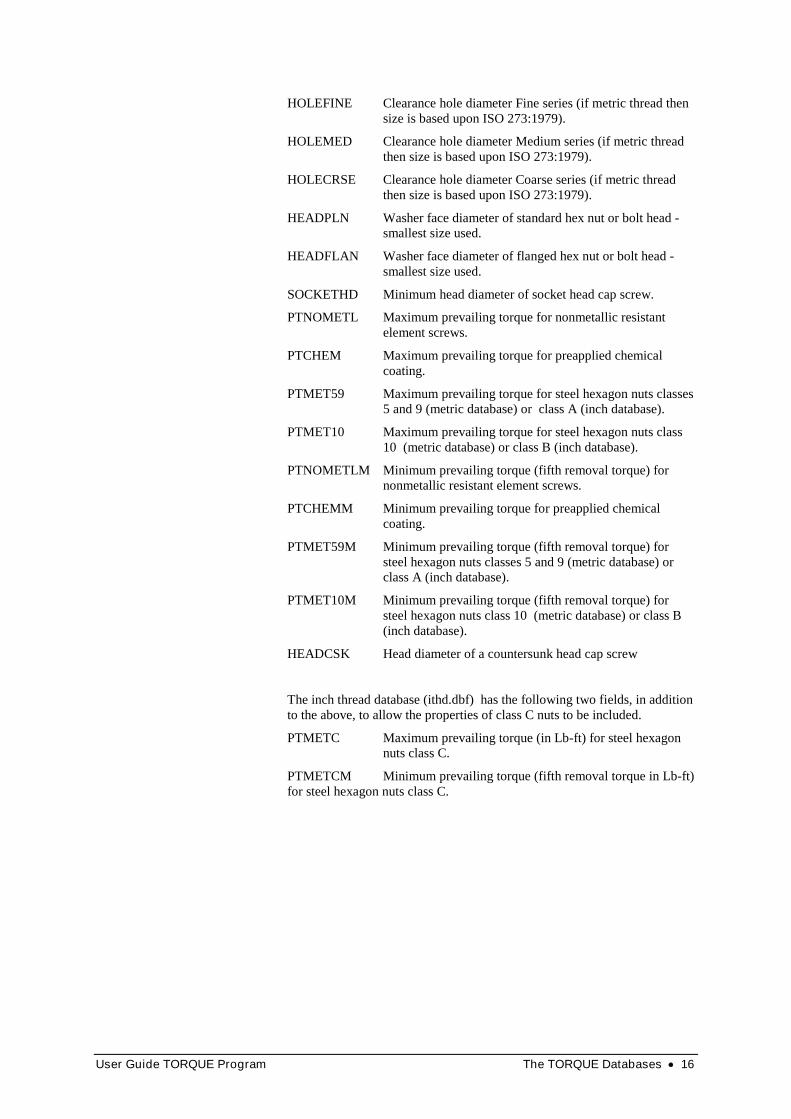
HOLEFINE Clearance hole diameter Fine series (if metric thread then size is based upon ISO 273:1979).
HOLEMED Clearance hole diameter Medium series (if metric thread then size is based upon ISO 273:1979).
HOLECRSE Clearance hole diameter Coarse series (if metric thread then size is based upon ISO 273:1979).
HEADPLN Washer face diameter of standard hex nut or bolt head -smallest size used.
HEADFLAN Washer face diameter of flanged hex nut or bolt head -smallest size used.
SOCKETHD Minimum head diameter of socket head cap screw.
PTNOMETL Maximum prevailing torque for nonmetallic resistant element screws.
PTCHEM Maximum prevailing torque for preapplied chemical coating.
PTMET59 Maximum prevailing torque for steel hexagon nuts classes 5 and 9 (metric database) or class A (inch database).
PTMET10 Maximum prevailing torque for steel hexagon nuts class 10 (metric database) or class B (inch database).
PTNOMETLM Minimum prevailing torque (fifth removal torque) for nonmetallic resistant element screws.
PTCHEMM Minimum prevailing torque for preapplied chemical coating.
PTMET59M Minimum prevailing torque (fifth removal torque) for steel hexagon nuts classes 5 and 9 (metric database) or class A (inch database).
PTMET10M Minimum prevailing torque (fifth removal torque) for steel hexagon nuts class 10 (metric database) or class B (inch database).
HEADCSK Head diameter of a countersunk head cap screw
The inch thread database (ithd.dbf) has the following two fields, in addition to the above, to allow the properties of class C nuts to be included.
PTMETC Maximum prevailing torque (in Lb-ft) for steel hexagon nuts class C.
PTMETCM Minimum prevailing torque (fifth removal torque in Lb-ft) for steel hexagon nuts class C.

User Guide TORQUE Program Glossary of Terms 17
Glossary of Terms
The stress under the bolt head or nut face. It is the total force in the bolt divided by the area between the inner diameter of bolt head or nut face and the outside diameter.
This is a slight taper on the hole, which is usually encountered on most drilled holes to some degree. The cause of this tapering is torsional and transverse flexibility of the drill together with instability of the drill point during entry into the material.
A tapered surface that is usually present at the starting end of an externally threaded fastener to aid starting the thread.
A tapered section at a start of a hole. Internal threads are often countersunk to aid mating with the external thread.
A tapered section at a start of a hole. Internal threads are often countersunk to aid mating with the external thread.
The decompression point is a term used to denote the condition at which there is zero pressure at the joint interface as a result of forces applied to the joint. If the applied force is increased beyond the decompression point, a gap will form at the interface. Analytically, a criterion of joint failure is often taken as when the applied force on the joint reaches the decompression point. This is because forces acting on the bolt(s) can dramatically increase at this point. Loading beyond this point can also result in fretting at the interface that will lead to bolt tension loss that will subsequently lower the decompression point. This process can continue until bolt failure does occur. The failure can be by fatigue or other mechanism but the underlying cause was loading of the joint beyond the decompression point. It is for this reason that it is frequently taken as a failure criteria in analysis work.
A screw thread that is formed on an external cylinder, such as on bolts, screws, studs etc.
The tendency for materials to fail under repeated loading at a stress level considerably less than the static strength of the material. This characteristic of materials is known as fatigue and it is a common cause of failure in many products, including bolts.
A dimensionless number representing the ratio of the friction force to normal force. Typically for threaded connections it is about 0.12 but can vary significantly depending upon the materials used and whether a lubricant has been used.
Mechanical resistance to the relative movement of two surfaces.
A 'hard' joint has a high stiffness (does not compress significantly under the loading applied by the bolt). A hard joint is defined (according to ISO 5393) as one whose torque value is achieved after the bolt has turned approximately 30 degrees of rotation from the snug level. The 'snug' state is
bearing stress
bell mouthing
chamfer
countersink
countersunk
decompression point
external thread
fatigue
friction
friction
hard joint

User Guide TORQUE Program Glossary of Terms 18
when the plates comprising the joint are in metal to metal contact - no gaps present.
A screw thread which is formed in holes, such as in nuts.
This ratio is the nominal ratio of the uncorrected shear strength of the internal thread compared to the uncorrected shear strength of the external thread.
The nominal length of engagement of the external thread into the internal thread.
The major diameter of an external thread is the diameter of an imaginary cylinder parallel to the crests of the thread. Both maximum and minimum diameters are requested to be entered. If a standard ISO metric thread size is being used than the program will present values appropriate for a 6H/6g nut/bolt tolerance class. These values can be over written if required.
The minor or root diameter is the diameter of a cylinder that just touches the roots of the thread.
This is the diameter commonly used to describe the thread. For example, for a M8x1.25 fastener the nominal thread diameter is 8mm.
Under load, the wedging action of the threads causes dilation of the nut resulting in an increase in the minor diameter of the nut and reducing the effective shear areas of both the external and internal threads.
This is the distance from the top of one thread crest to the next. If the outside diameter entered previously is the same as that for a standard metric thread, the pitch for this thread will be shown. For example if 8mm was previously entered for the nominal diameter then on entering this field a value of 1.25mm would be shown.
The pitch or effective thread diameter of the external thread is the diameter that has equal metal and space widths. Put more simply, it is the mean diameter of the thread.
The clamp generated by a bolt or other threaded fastener when initially tightened.
The prevailing torque is the torque required to run a nut (or bolt) down a thread on certain types of fasteners that are designed to resist vibration loosening. This prevailing torque can be provided by an insert in the nut/bolt thread, by using nuts that have their threads locally distorted or by using micro-encapsulated adhesive applied to the threads.
A designation system which defines the strength of a bolt or nut. For metric fasteners, property classes are designated by numbers where increasing numbers generally represent increasing tensile strengths. The designation symbol for bolts consists of two parts:
1. The first numeral of a two digit symbol or the first two numerals of a three digit symbol approximates 1/100 of the minimum tensile strength in MPa.
2. The last numeral approximates 1/10 of the ratio expressed as a percentage between minimum yield stress and minimum tensile stress.
Hence a fastener with a property class of 8.8 has a minimum tensile strength of 800 MPa and a yield stress of 0.8x800=640 MPa.
The designation system for metric nuts is a single or double digit symbol. The numerals approximate 1/100 of the minimum tensile strength in MPa. For example a nut of property class 8 has a minimum tensile strength of 800 MPa. A bolt or screw of a particular property class should be assembled
internal thread
Internal to External Thread Strength Ratiolength of thread engagementMajor Diameter
Minor Diameter
Nominal Thread Diameter
nut dilation
Pitch
Pitch Diameter
preload
prevailing torque
property class
User Guide TORQUE Program Glossary of Terms 19
with the equivalent or higher property class of nut to ensure that thread stripping does not occur.
This is the shear strength for the material divided by the tensile strength. For steel, typically this ratio is 0.6 (higher for lower tensile steels and slightly lower for high tensile), that is the shear strength of steel is typically 60% of the tensile strength.
This is the shear area of the external thread in the unstrained condition. It is equal the area of intersection of a cylinder of diameter of the nut minor diameter acting on the mating external thread profile. The calculated area takes into account bell mouthing, if present in the internal thread. The critical dimensions for this area are the length of thread engagement and the maximum internal thread minor diameter.
This is the shear area of the internal thread in the unstrained condition. It is equal to the area of intersection of a cylinder equal to the major diameter of the external thread acting on the mating internal thread profile. The critical dimensions for this area are the length of thread engagement and the minimum major diameter of the external thread.
The maximum stress applied by nearly co-linear equal and opposite forces that can be sustained by a material before fracture occurs. If the shear strength is exceeded in the threads of a fastener, shearing (stripping) of the threads occurs. For metric fasteners the units used are megapascals (Mpa or N/mm²), for inch based fasteners the units used are lbf/in².
A 'soft' joint has low stiffness and whose final torque is reached after approximately 720 degrees of bolt rotation (according to ISO 5393).
The effective cross sectional area of a thread when subjected to a tensile force. It is based upon a diameter which is the mean of the pitch (or effective) and the minor (or root) diameters of the thread. The use of this diameter stems from the work of E. M. Slaughter in the 1930's. He completed carefully controlled tests using various sizes of standard threads and compared their strength with machined bars made from the same bar of material. He found that this mean diameter give results that agreed with the tensile test results to within about 3%. The error on the minor and pitch diameters was about 15%. Tests completed subsequent to these by other investigators have also shown that the stress diameter is a reasonable approximation to a threads tensile strength. (Reference: 'Tests on Thread Sections Show Exact Strengthening Effect of Threads.' by E. M. Slaughter, Metal Progress, vol 23, March 1933 pp. 18-20)
The size of the drill that is used to produce the hole to allow an internal thread to be formed. The minor diameter of the internal thread is the diameter of the drill used to create the hole.
Thread stripping is a shear failure of an internal or external thread that results when the shear strength of the threaded material is exceeded by the applied forces acting on the thread.
The tightening factor is a measure of the scatter in a bolt's clamp force because of the tightening method used to tighten the fastener. It is defined as the maximum bolt preload divided by the minimum value anticipated for that tightening method.
A combination of tolerance grade and a fundamental deviation which is given to an internal or external thread. A tolerance class for an internal thread when combined with the tolerance class for an external thread gives the class of fit for the mating threads.
Specifying how tight (the amount of preload present) a bolt or threaded fastener should be by specifying a torque that should be applied.
ratio of shear strength to tensile strength
shear area of the external thread
shear area of the internal thread
shear strength
soft joint
stress area
tapping drill
thread stripping
tightening factor
tolerance class
torque control