
Torque converter principles - صندوق...
69
Torque converters Torque converter principles Summary A single stage torque converter has three elements: the impeller, the turbine and the stator. The purpose of a light vehicle transmission is to transmit engine torque to the driving wheels. It also has to provide for this torque to be increased or decreased to suit differing road and operating conditions. In a manual transmission this is done by the driver, manually selecting gear ratios to suit. In an automatic transmission, it is done by both the transmission control system, automatically selecting the gearing according to load and speed, and by the torque converter. The torque converter is mounted on the engine in the same place as a manual clutch, and does the same job, transmitting engine torque to the input shaft of the transmission. It can also multiply torque according to driving conditions. It’s a fluid coupling, with the fluid acting as the driving medium, since none of the converter components are physically connected to the others. It acts as an automatic clutch. At engine idle speeds, it allows the engine to operate while the vehicle is stationary and the transmission is in a drive range. In its simplest form, a single-stage torque converter has three elements: The Impeller, the Turbine and Stator. All three have angled or curved vanes and are contained in a single casing. They are separated from each other by thrust bearings, but maintain a close relationship for efficient torque transmission.
Transcript of Torque converter principles - صندوق...

Torque converters
Torque converter principles Summary A single stage torque converter has three elements: the impeller, the turbine and the stator.
The purpose of a light vehicle transmission is to transmit engine torque to the driving wheels. It also has to provide for this torque to be increased or decreased to suit differing road and operating conditions.
In a manual transmission this is done by the driver, manually selecting gear ratios to suit.
In an automatic transmission, it is done by both the transmission control system, automatically selecting the gearing according to load and speed, and by the torque converter.
The torque converter is mounted on the engine in the same place as a manual clutch, and does the same job, transmitting engine torque to the input shaft of the transmission. It can also multiply torque according to driving conditions.
It’s a fluid coupling, with the fluid acting as the driving medium, since none of the converter components are physically connected to the others. It acts as an automatic clutch. At engine idle speeds, it allows the engine to operate while the vehicle is stationary and the transmission is in a drive range. In its simplest form, a single-stage torque converter has three elements: The Impeller, the Turbine and Stator.
All three have angled or curved vanes and are contained in a single casing. They are separated from each other by thrust bearings, but maintain a close relationship for efficient torque transmission.

The impeller has a large number of vanes attached to the converter case to form the driving member. The vanes rotate with the casing as the engine rotates. Each one has a slight curvature and is set radially in the case.
The turbine is similar in construction to the impeller, but with more vanes, and with a greater curvature. The direction of curvature of the turbine vanes is opposite to that of the impeller vanes. The turbine is free to rotate in the casing, and a central spline mates with a spline on the input shaft. When the fluid coming from the impeller rotates the turbine, the transmission input shaft also rotates.
Both the impeller and the turbine are fitted with a torus or guide ring. This helps to secure the vanes in position. It also reduces turbulence at the center to improve efficiency.
The stator has a small set of curved blades attached to a central hub and is positioned between the impeller and the turbine. The central hub is mounted on a one-way clutch, splined to a stator support shaft, and fixed to the transmission case. The one-way clutch allows the stator to rotate only in the same direction as the impeller. Trying to rotate the stator in the opposite direction locks the stator on the support shaft and holds it stationary.
Converter operation Summary The stator redirects the fluid coming from the turbine so that it re-enters the impeller travelling in the same direction as impeller rotation. This provides torque multiplication.
When the engine starts, and idles, the transmission pump rapidly fills and pressurizes the converter.
The impeller is driven by the engine and turns at crankshaft speed.
With the selector lever in the Neutral or Park position, the turbine also rotates, carried around by momentum of the fluid.

When a drive position is selected, the turbine shaft is locked to the transmission output shaft through the transmission gearing, and the turbine comes to a halt.
Centrifugal force throws fluid between the impeller vanes outwards, around the back of the guide ring in a forward direction. This is due to the shape of the casing and the curvature of the vanes.
With the engine idling and the vehicle stationary, little torque is transferred from impeller to turbine, as the fluid flow is too gentle.
When the engine accelerates, higher impeller speed discharges the fluid across and against the turbine vanes with greater force.
Fluid exits the impeller at high velocity and enters the turbine at its outer edge.
This exerts a turning effort against the back of the turbine vanes, which absorbs energy in the fluid, causing the turbine to rotate, and transferring the drive to the transmission.
The fluid, still at high velocity, now flows between the turbine vanes, leaving the turbine in a direction opposite to impeller rotation.
This is due to the curvature of the turbine vanes.
Unchecked, this would oppose impeller rotation and reduce turning effort.
To defeat this, the stator re-directs the fluid. It re-enters the impeller in the same direction as impeller rotation.
The fluid strikes the forward face of the stator blades with a backward force, which locks the stator on the one-way clutch.
The stationary stator and the angle of the blades change the direction of the fluid flowing between them.
The fluid re-enters the impeller at high velocity, in the same direction as impeller rotation.
It strikes the back of the impeller vanes with considerable force, giving up energy to assist the engine in turning the impeller.
This provides torque multiplication.
Torque multiplication Summary Torque multiplication is proportional to the difference in speed between the impeller and the turbine.

Torque multiplication exists only when there is a difference in speed between the impeller and the turbine.
The magnitude of torque multiplication depends on load. When the turbine is stalled, it has a maximum value of about 2.2 to 1.
Stall is an operating condition where the turbine is stationary and the engine throttle is wide open, making the rotational speed of the impeller as high as possible.
Stall can be approximated to when a vehicle moves from rest, up an incline, towing a heavy caravan or car trailer.
Instantaneously, as the vehicle begins to move, maximum torque multiplication occurs.
At an engine speed of 2100 RPM, and torque at that speed of 100 Newton meters, the torque input to the transmission will be 2.2 times that value - 220 Newton meters.
This multiplication tapers off as the turbine commences to turn and increases in speed. This subjects the fluid in the turbine passages to centrifugal force, which slows down the circulation between impeller and turbine.
When turbine speed reaches around 90% of impeller speed, torque multiplication falls to zero. Torque transfer from impeller to turbine is then about 1 to1. This is known as the coupling point.
At coupling point, fluid flow from the turbine vanes is relatively low, but it is at high speed, in the direction of rotation. The rapidly turning turbine discharges its fluid against the back of the stator blades. This force unlocks the stator and all three elements rotate as one unit. Unlocking the stator prevents turbulence in the fluid and any braking effect on the engine.
Fluid flow

Summary Rotary flow, vortex flow and spiral flow are terms which describe fluid flow paths in the torque converter. These paths are dependent on operating conditions.
The revolving impeller carries the fluid with it, inside the converter casing. The fluid is rotating around the axis of the converter. This is known as the Rotary flow.
At the same time, centrifugal force moves the fluid outwards, away from the converter axis.
During torque multiplication, the shape of the converter case makes the fluid flow in a circular motion, through the impeller, turbine and stator. This is known as the Vortex flow.
Combining these two fluid flows produces a progressive circular, or spiralling motion. This is known as the Spiral flow.
In a stalled converter, fluid flows at high velocity from the revolving impeller through the stationary turbine and stator. This results in a fast moving vortex flow and high torque multiplication.
When the turbine starts to rotate and increases in speed, the centrifugal force on the fluid in the turbine opposes the high velocity flow from the impeller. This reduces vortex flow and torque multiplication.
At coupling point, the vortex flow of fluid is slight and there is no torque multiplication. The converter now acts as a fluid coupling.
During acceleration or hill climbing, torque needed by the drive shaft can exceed the engine output torque. As a result, the turbine slows, causing an increase in vortex flow. This again causes torque multiplication.
The converter automatically adjusts its output, within design limits, to meet drive shaft requirements.
Heat exchanger

Summary Converter operation produces heat which is usually dissipated by passing the transmission fluid through a heat exchanger in the cooling system.
Converter slip, and loss of power through the transmission produces heat, which must be dissipated.
At stall, a lot of engine output is converted into heat, and this brings the oil operating temperature closer to its boiling point.
Excessive temperature rise can produce cavitation bubbles in the fluid, which produces noise and reduces converter efficiency.
Some converters use external fins on the case to circulate air through the housing, onto the converter.
Most automatic transmission vehicles use a heat exchanger in the lower tank of the radiator.
Fluid flows from the pump to the converter, then through the heat exchanger before returning to the transmission.
Lock-up converters Summary In a lock-up converter, the impeller and turbine are locked together when operating conditions are suitable to provide a one to one drive from the engine to the transmission input shaft.

In a lock-up converter, the impeller and turbine are locked together when conditions are suitable, to provide a 1 to 1 drive from the engine to the transmission input shaft.
Lock-up normally occurs at higher road speeds when light throttle openings are being used.
The lock-up piston engages in slots in the turbine and can move axially, for engagement, and disengagement.
Torsional damper springs are built into the turbine/ piston assembly. When the clutch is engaged, these springs dampen drive-line, and torsional vibrations.
When the clutch facing on the piston comes in contact with the internal machined surface on the wall of the converter housing, lock-up occurs.
This provides a 1 to 1 connection from engine to transmission, with no slippage between components.
Sprag one way clutches Summary The stator one way clutch prevents the stator from turning in the opposite direction to engine rotation during torque multiplication. It allows the stator to rotate with the impeller and turbine when coupling point is reached.
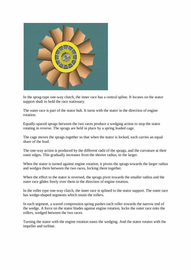
In the sprag-type one-way clutch, the inner race has a central spline. It locates on the stator support shaft to hold the race stationary.
The outer race is part of the stator hub. It turns with the stator in the direction of engine rotation.
Equally-spaced sprags between the two races produce a wedging action to stop the stator rotating in reverse. The sprags are held in place by a spring loaded cage.
The cage moves the sprags together so that when the stator is locked, each carries an equal share of the load.
The one-way action is produced by the different radii of the sprags, and the curvature at their outer edges. This gradually increases from the shorter radius, to the larger.
When the stator is turned against engine rotation, it pivots the sprags towards the larger radius and wedges them between the two races, locking them together.
When the effort to the stator is reversed, the sprags pivot towards the smaller radius and the outer race glides freely over them in the direction of engine rotation.
In the roller type one-way clutch, the inner race is splined to the stator support. The outer race has wedge-shaped segments which retain the rollers.
In each segment, a waved compression spring pushes each roller towards the narrow end of the wedge. A force on the stator blades against engine rotation, locks the outer race onto the rollers, wedged between the two races.
Turning the stator with the engine rotation eases the wedging. And the stator rotates with the impeller and turbine.

Planetary gearing
Planetary gears Summary A simple planetary gearset has a sun gear, planet pinions mounted on a planet carrier, and a ring gear.
Most automatic transmissions use epicyclic or planetary gears. They are constantly in mesh with each other.
A basic planetary gearset has a sun gear, which meshes with planet gears, also called planet pinions.
The planet pinions, in sets of three or more, rotate on bearings, on hardened steel pins, on a planet carrier, which spaces the pinions equally around the sun gear. It also locates them so they can mesh with an internally toothed ring gear.
This means the planet pinions are always in mesh with the sun gear and the ring gear.
In operation, their motion is described as either “Walking" or "Idling".
“Walking” means that if either the sun gear, or the ring gear, is held stationary, the alternative driving member rotates the planet gears on their pins. This turns the planet carrier in the same direction as the driving member.
Planet gears always turn in the same direction on their pins as planet carrier rotation, while they walk around a stationary sun gear. They always turn in the opposite direction on their pins while walking inside a stationary ring gear.

"Idling" refers to the rotation of the planet gears on their pins whenever the planet carrier is stationary. Torque is transmitted from the sun gear to the ring gear, or from the ring gear to the sun gear, via the planet gears and the stationary carrier.
In both cases the driven member is turned in the opposite direction to the driving member. To provide the ratios available from the gearset, one or more of the components must be held - or released. This is normally done by hydraulic servos, operated by transmission fluid under pressure, acting on lined bands or clutches, or, by one-way clutches. They allow turning in one direction, but act as a lock-up, or reaction member in the opposite direction.
In practice, a combination of these is normally used.
Simple planetary gearsets Summary A simple planetary gearset can illustrate how to control individual members to produce a particular drive output, or neutral.
A simple planetary gearset can illustrate how to control individual members to produce a particular output or neutral.
This planet carrier is attached to the output shaft. The sun gear is attached to the input shaft from the turbine.
The ring gear is not held. When the input shaft rotates the sun gear, the planet gears idle on their stationary carrier pins, and turn the ring gear in the opposite direction to engine rotation.
This free rotation of the gears provides neutral. No drive is transmitted to the output.
For low gear, a brake band, anchored to the transmission case, is placed around the ring gear. Applying this holds the ring gear stationary.
Now when the sun gear rotates, the planet gears can no longer idle. They must walk around the inside of the stationary ring gear.

The planet carrier must move with them in the same direction as engine rotation, but at a slower speed. And with an increase in torque.
A direct-drive or top-gear condition with a 1 to 1 ratio is obtained by locking together any 2 members of the gearset.
A multi-plate clutch can be used for this purpose.
The outer drum and outer plates are attached to the ring gear. The inner plates and inner drum are attached to the planet carrier.
When fluid under pressure is directed onto the clutch piston, the clutch plates are locked together. This locks the planet carrier to the ring gear.
Now when the sun gear is rotated, the planet gears can neither idle nor walk. The whole gearset turns as one unit to give a direct drive.
For reverse, the ring gear is attached to the output shaft, and the planet carrier is held stationary by a brake band.
Rotating the sun gear causes the planet gears to idle on their stationary pins. This turns the ring gear, and its output shaft, in the opposite direction to engine rotation.
Automatic transmission brake bands Summary Brake bands in automatic transmissions are externally contracting types which are operated by hydraulic servos.
All bands are externally contracting types and have a thin layer of plain or grooved friction material bonded onto a spring steel or cast steel backing.
One end of the band rests against a stop or strut in the transmission case. The other end accommodates a push rod or linkage from a hydraulically operated servo, which contracts the band onto the drum.
The simplest servo consists of a cylinder containing a piston, a piston return spring, and a pushrod.
Fluid leakage past the piston is normally prevented by neoprene type seals.
Fluid under pressure is directed onto the piston in the closed cylinder, moving it to apply the band.
When this fluid is "dumped" or exhausted from the supply line, the spring returns the piston. And the flexible band springs back to its released position.
In a pressure release type servo, the band is applied in the normal way by fluid pressure acting on the piston head.
However this fluid is not dumped to accomplish band release.
Release is obtained by supplying fluid at the same pressure to the opposite side of the piston.
As soon as pressure is equal on both sides of the piston, the piston is moved to the release position by the force of the return spring, acting on the release side.
The band’s speed of application, or release, is controlled by the rate at which fluid on the release side enters or leaves the servo.
When admitting release fluid is unrestricted, the band is released quickly.
When dumping it is unrestricted, a snap-band application occurs. This is because fluid under pressure is already acting on the servo piston.
Pressure-release servos can also have pistons with unequal areas.
In this case the release side has a larger surface area than the apply side.
The band is brought into operation by directing fluid onto the reduced area that surrounds the hollow portion, accommodating the return spring.
When fluid at the same pressure is directed to the release side, the differential area results in a higher release force. The band can be released even while apply fluid continues to exert force on the piston
The fluid directed to the release side can be directed at the same time to a clutch piston, to bring the next component into operation.
Multi-disc clutches

Summary In most transmissions, planetary gear members and shafts are coupled together by multiple-disc clutches. They can also hold members to the case instead of using bands.
Multiple-disc clutches can be used to hold members to the case instead of using bands but in most transmissions, they couple planetary gear members and shafts together.
A servo-operated band can only hold a member stationary, but multiple-disc clutches can hold or drive individual members.
They have a set of driving plates, and a set of driven plates, collectively called a clutch pack.
Both sets may be spring steel, but one has friction material bonded onto both faces, and since they operate in the transmission fluid they are called wet clutches.
The friction material may be plain or grooved. Grooving allows for fluid to escape from between the plates when the clutch engages.
The steel plates may be dished, or waved, with alternate high and low segments. This design promotes smooth engagement.
The size and number of plates in a clutch pack depends on the maximum torque it is required to transmit.
Three to five plates of each type are commonly used.
The plates are pressed together for engagement by a hydraulically-operated piston. It moves in a short cylinder in a clutch drum, or in a cylinder machined in the casing.
Release can be effected by one large coil spring, or by a pack containing many small springs.
When a diaphragm spring is used, it gives extra leverage to increase the apply force as well as providing the release force.

The outer circumference of the diaphragm spring rests against a step in the clutch drum. The piston pushes against the inner circumference of the spring to apply the clutch.
The force exerted on the clutch pack is multiplied by leverage from the diaphragm, as it pivots against the pressure plate.
Plate clearance Summary In the released position, the plates must retain a set clearance. This allows them to separate from one another and avoid excessive or premature wear.
In the released position, the plates must retain a set clearance. This allows them to separate from one another and avoid excessive or premature wear.
Premature wear can also be caused by partial application of a clutch at high speed. This can occur if fluid is trapped in the clutch cylinder after release.
Trapped fluid accumulates at the outer portion of the cylinder. At high speed and under the action of centrifugal force, this can produce enough pressure to effect partial application.
This can be prevented by a pressure relief valve in the piston.
It is normally a flat-reed or ball-check type, which is easily closed by the apply fluid.
On release, the valve is unseated by the rotation of the assembly, letting fluid escape.
One-way clutches are used in the gear train to allow rotary motion in one direction only.
They simplify the hydraulic and mechanical control of the members.
The hydraulic control system requires a continuous supply of fluid under pressure, normally provided by a fixed displacement pump. It is driven by the torque converter when the engine is running.

The pump driving member is engaged by tangs on the converter spout, or machined flats, or by slots.
Pump output always exceeds normal operating demands so pressures are controlled by regulating valves. Excess fluid returns to the pump inlet or is dumped into the oil pan, where it can reach the pump intake strainer.
Crescent-type pumps are commonly used in automatic transmissions.

Electronic control transmission
Electronic control Summary In an electronically controlled transmission, the speed of the vehicle and the throttle opening are sensed by the vehicle speed sensor, and the throttle position sensor.
A fully hydraulically-controlled transmission controls the shift points by a hydraulic control unit or valve body.
Fluid for transmission operation and lubrication is supplied by the pump. Pressure-control valves determine the pressures in the system according to operating conditions.
These conditions are signalled to the control valves and two inputs are critical.
Engine Load, and Vehicle Speed
The Engine Load signal can come via a cable connected to the throttle linkage. The Speed Signal is provided by a governor valve, attached to the transmission output shaft.
In an electronically controlled transmission, the speed of the vehicle and the throttle opening are sensed by the vehicle speed sensor, and the throttle position sensor. This information is sent as electrical signals to an ECU.
The ECU combines this input data with information in its memory, then sends output signals to electrical solenoids in the hydraulic control unit. The solenoids control the movement of the shift valves, which in turn controls the shifting of the transmission.
Fully hydraulically controlled transmission
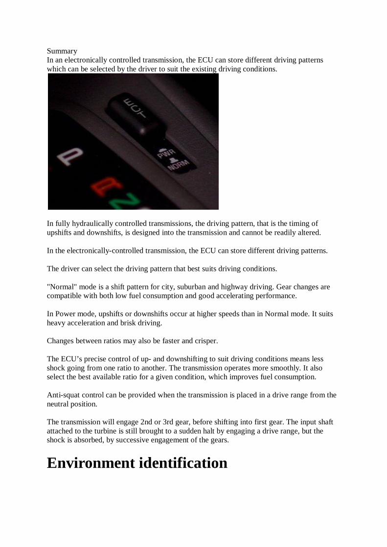
Summary In an electronically controlled transmission, the ECU can store different driving patterns which can be selected by the driver to suit the existing driving conditions.
In fully hydraulically controlled transmissions, the driving pattern, that is the timing of upshifts and downshifts, is designed into the transmission and cannot be readily altered.
In the electronically-controlled transmission, the ECU can store different driving patterns.
The driver can select the driving pattern that best suits driving conditions.
"Normal" mode is a shift pattern for city, suburban and highway driving. Gear changes are compatible with both low fuel consumption and good accelerating performance.
In Power mode, upshifts or downshifts occur at higher speeds than in Normal mode. It suits heavy acceleration and brisk driving.
Changes between ratios may also be faster and crisper.
The ECU’s precise control of up- and downshifting to suit driving conditions means less shock going from one ratio to another. The transmission operates more smoothly. It also select the best available ratio for a given condition, which improves fuel consumption.
Anti-squat control can be provided when the transmission is placed in a drive range from the neutral position.
The transmission will engage 2nd or 3rd gear, before shifting into first gear. The input shaft attached to the turbine is still brought to a sudden halt by engaging a drive range, but the shock is absorbed, by successive engagement of the gears.
Environment identification
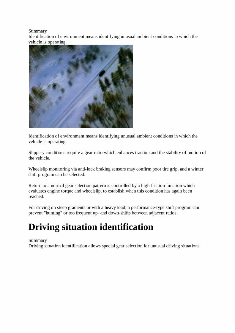
Summary Identification of environment means identifying unusual ambient conditions in which the vehicle is operating.
Identification of environment means identifying unusual ambient conditions in which the vehicle is operating.
Slippery conditions require a gear ratio which enhances traction and the stability of motion of the vehicle.
Wheelslip monitoring via anti-lock braking sensors may confirm poor tire grip, and a winter shift program can be selected.
Return to a normal gear selection pattern is controlled by a high-friction function which evaluates engine torque and wheelslip, to establish when this condition has again been reached.
For driving on steep gradients or with a heavy load, a performance-type shift program can prevent "hunting" or too frequent up- and down-shifts between adjacent ratios.
Driving situation identification Summary Driving situation identification allows special gear selection for unusual driving situations.

In specific driving situations, it can be beneficial to select a gear not normally selected in a shift program.
A normal shift program characteristic initiates shift changes according to road speed and throttle opening angle.
Shift characteristics are arranged so that up-shifts are triggered by an increase in road speed or by reduced throttle opening.
Down-shifts occur when the opposite situations apply.
But in some situations, as when the brakes are applied when cornering or descending gradients, unwanted gear shifts may occur.
If additional inputs are used to determine these circumstances then an optimum ratio can be selected.
Four special functions are provided.
Fast-off identification, Downhill gradient identification, Corner identification, and Stop-and-go identification.
Fast-off identification Summary The driver's intention to brake can often be detected by the rapid and complete release of the accelerator pedal, and an unnecessary upshift in gear ratio can be prevented.

In order to slow the vehicle, the driver lifts his or her foot off the accelerator and if necessary applies the brakes.
In normal driving, closing the throttle prompts the transmission to upshift to a higher ratio, if it is not already in top gear.
In a higher gear the engine contributes less to the braking process, and when the accelerator is depressed again, a downshift usually takes place.
These unnecessary shifts can be prevented by the Fast-off identification function.
Corner identification Summary The radius of a curve can be identified by comparing the differences in the rotating speed of the inner and outer front wheels when the vehicle is not travelling in a straight line.
The fast-off identification function can also apply when the vehicle approaches a corner.
Rapidly releasing the accelerator may inhibit an upshift if the vehicle is not already in top gear.
But if upshift has been avoided by fast-off identification, it is still not desirable to upshift on the actual corner, even if the accelerator is depressed again.
So, upshifts are prevented when a pre-set rate of lateral acceleration is exceeded.
The radius of the curve is determined by comparing the rotating speeds of the inner, and outer front wheels, when the vehicle is not traveling in a straight line.
This data from the wheel sensors, added to road speed, allows a sufficiently accurate estimate of lateral acceleration.
If corners are taken at a particularly high rate of lateral acceleration, down-shifts are also inhibited.
For data from the wheel sensors to be accurate, it is essential the two front wheels have the same dynamic circumference.
This is monitored continuously by the diagnostic circuits. Any discrepancies, perhaps from different tire pressures, will deactivate the corner identification.
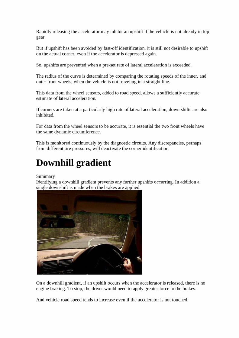
Downhill gradient Summary Identifying a downhill gradient prevents any further upshifts occurring. In addition a single downshift is made when the brakes are applied.
On a downhill gradient, if an upshift occurs when the accelerator is released, there is no engine braking. To stop, the driver would need to apply greater force to the brakes.
And vehicle road speed tends to increase even if the accelerator is not touched.

Identifying a closed throttle and increasing road speed causes the system to respond initially by preventing further upshifts.
If brakes are then applied, a single downshift takes place. Downshift only occurs below a pre-set engine speed. This avoids application of peak engine braking torque.
The downhill identification gradient mode becomes inactive once the accelerator is depressed again.
Stop & go Summary In dense traffic, only a small proportion of the vehicle's performance is needed to keep it moving and first gear may not be engaged.
In dense traffic, only a small proportion of the vehicle's performance is needed to keep it moving.
For a powerful vehicle, second gear is adequate when accelerating from a standstill.
A stop-and-go situation is identified if the throttle opening angle and the road speed remain below pre-set limits for a given period of time.
This prevents shifting down to first gear.
That makes progress smoother, lowers fuel consumption and reduces any tendency to creep forward from a standstill.
When the pre-set load/speed range is exceeded, first gear is no longer inhibited.
Manual selection

Summary A chosen gear ratio can be selected manually by using the selector lever in manual mode.
Despite the benefits of adaptive control, a particular ratio can still be selected manually.
In Steptronic applications, the manual program is available by moving the selector lever to the left of the ‘D’ position.
Automatic changes continue in a Sport program until the lever is operated in a one-touch movement towards the manual mode.
Forward movement changes the transmission to a higher gear. Backward movement to a lower gear.
Overspeed protection prevents a gear engagement lower than the governed engine speed.
And when a low ratio is selected for acceleration, a shift up to the next higher gear takes place shortly before the governed speed is reached.
Kick-down initiates downshifts in all speeds to the lowest available ratio, and at low speeds, automatic downshifts as far as third gear occur to ensure adequate traction for re-acceleration.

Layout & operation
Borg Warner 35 gearbox Summary The Borg Warner 35 is a fully hydraulically controlled transmission which has three forward ratios and reverse.
In a Borg Warner Model 35 transmission there are three forward gear ratios and reverse
The selector lever works in a quadrant which has six stations,
They denote Park, Reverse, Neutral, Drive, Second and First.
When the transmission is placed in "D" or Drive range, the vehicle will move off in first gear and will change to second and then to third gear in accordance with road speed and engine load.
Downshifts from third to second and from second to first are also fully automatic, unless the driver resorts to kickdown
Kickdown changes are useful when short bursts of acceleration are required and occur at higher speeds than automatic changes.
Automatic upshifts take place immediately accelerator pressure is eased off following a kickdown.

Selector positions Summary Automatic control of gear changes may be over-ridden by use of the 2 and 1 selector positions.
Automatic control of gear changes may be overridden by use of the 2 and 1 selector positions.
If 1 is selected from rest, 1st gear will be held until the selector is moved to 2, when 2nd gear will engage.
Moving the lever to D will then give third gear, provided that road speed and throttle opening are suitable.
Selector position 2 also permits automatic changes but these will be from 1st to 2nd and from 2nd to 1st only, depending on road speed and throttle opening. Third gear will not engage in this position.
When the vehicle is cruising in third gear, and the selector lever is moved to 2, an immediate down change to 2nd will take place.
If the selector is moved to 1, an immediate down change to 2nd will take place with a further down change to 1st when the road speed drops sufficiently.
Full engine braking is available in both 2nd and 1st gears and this also applies when the vehicle is operating in reverse.
Planetary gearset Summary The planetary gearset is a Ravigneaux type with primary and secondary sun gears, primary and secondary planet pinions and a ring gear.

The planetary gearset is a Ravigneaux type with primary and secondary sun gears, primary and secondary planet pinions, and one ring gear.
The ring gear is attached to the output shaft and the planet carrier is mounted in the transmission case on a one-way clutch which locates in a central support, held in position by dowel bolts.
Both sets of pinions are mounted in the planet carrier so that they mesh together in pairs and the longer outer secondary pinions mesh with the ring gear at their outer edge.
At their inner edge they mesh with the secondary sun gear, while the smaller primary pinions mesh with the smaller primary sun gear.
The planet pinions transmit the drive from the sun gears to the ring gear.
In all forward ratios, drive is transmitted through the primary sun gear while in reverse it is transmitted through the secondary sun gear.
Control of the planetary gearset is provided by the operation of two multi-plate clutches, the one-way clutch and two brake bands.
The outer plates of the front clutch are splined to the input shaft from the converter turbine while the inner plates are splined to the primary sun gear shaft.
The inner plates of the rear clutch are splined to the front clutch drum and therefore to the converter turbine, and the outer plates connect to the secondary sun gear shaft.
The front band wraps around the outside of the rear clutch drum and the rear band is on the outside of the planet carrier so that it will hold the planet carrier stationary when it is applied.
When the rear band is in the release position, the one-way clutch allows the planet carrier to rotate in a forward direction but not in a reverse direction.

High range powerflow Summary In D range, the components and control elements in each gear determine the power flow through the gearset. In selector lever position 1, the front clutch and the rear band are applied. The rear clutch and the rear band are applied in order to obtain reverse gear.
This chart illustrates the components and which of the control elements are engaged in each range.
A is the front clutch.
B is the rear clutch.
C is the front band.
D is the rear band.
E is the one-way clutch.
The front clutch is engaged in all forward gears and combines with other elements to provide the required ratios according to selector lever position.
When D is selected the front clutch is engaged and the one-way clutch acts as the reaction member, holding the planet carrier stationary and preventing its rotation in the opposite direction to the input shaft.
Power flow is from the input shaft through the applied front clutch to the primary sun gear which turns in a clockwise direction.
Since the primary sun gear is meshed with the primary pinions, the pinions rotate in an anticlockwise direction and turn the secondary pinions clockwise on their pins, on the locked planet carrier.

The secondary pinions turn the ring gear and the output shaft in a clockwise direction at a reduced ratio and with an increase in torque.
The overall gear reduction in first gear is 2.39: 1.
The secondary sun gear rotates freely in the opposite direction to the primary sun gear.
On overrun, when torque is applied in the reverse direction, the one-way clutch unlocks and allows the planet carrier to rotate.
This means the transmission freewheels and there is no engine braking.
In selector lever position D and also in selector position 2, the front clutch and the front band are applied to obtain second gear.
When the transmission changes up from first to second, the front clutch remains engaged and the front band is applied to lock the secondary sun gear to the case.
The secondary sun gear now provides the reaction member and power flow is from the input shaft through the applied front clutch to the primary sun gear and to the primary pinions.
The anticlockwise rotation of the primary pinions turns the secondary pinions clockwise and since they are in mesh with both the secondary sun gear and the ring gear, the secondary pinions walk around the stationary sun gear and rotate the ring gear in a clockwise direction.
Torque reaction in both drive and overrun conditions is taken by the applied front band which holds in either direction.
The overall gear reduction in second gear is 1.45: 1.
In selector position D, the front and rear clutches are applied to obtain third gear.
When the transmission changes up from second to third the front clutch remains engaged. The front band is disengaged and the rear clutch is applied.
Since both clutches are now applied, the input shaft is now locked to the primary sun gear through the front clutch and to the secondary sun gear through the rear clutch.
With both sun gears locked together and to the input shaft, there can be no relative motion between the gears and the whole gearset rotates as one unit to give a direct drive with a ratio of 1:1.
Low range powerflow Summary The rear clutch and the rear band are applied in order to obtain reverse gear.
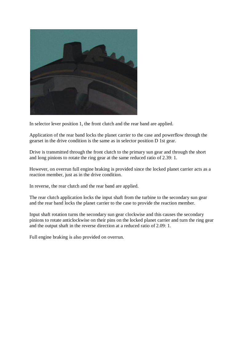
In selector lever position 1, the front clutch and the rear band are applied.
Application of the rear band locks the planet carrier to the case and powerflow through the gearset in the drive condition is the same as in selector position D 1st gear.
Drive is transmitted through the front clutch to the primary sun gear and through the short and long pinions to rotate the ring gear at the same reduced ratio of 2.39: 1.
However, on overrun full engine braking is provided since the locked planet carrier acts as a reaction member, just as in the drive condition.
In reverse, the rear clutch and the rear band are applied.
The rear clutch application locks the input shaft from the turbine to the secondary sun gear and the rear band locks the planet carrier to the case to provide the reaction member.
Input shaft rotation turns the secondary sun gear clockwise and this causes the secondary pinions to rotate anticlockwise on their pins on the locked planet carrier and turn the ring gear and the output shaft in the reverse direction at a reduced ratio of 2.09: 1.
Full engine braking is also provided on overrun.

Servos & clutches
Rear servo Summary The rear servo in a Borg Warner 35 transmission is a pressure apply/spring release type.
Servos are used in automatic transmissions to convert the hydraulic pressure acting on a piston to a mechanical force which is then applied to a brake band.
In the Borg Warner 35 transmission, two brake bands are used, a front band and a rear band, and a servo is required for the operation of each.
The rear servo is a pressure apply/spring release type and is engaged together with the rear clutch and its piston has a central stem which locates in one end of the rocker arm to transfer the apply force to the band.
A heavy lever type spiral spring returns the servo and the band to the Off position when the fluid is dumped.
The rear band holds the planet carrier stationary when it is engaged and since it is applied in drive ranges where low ratios are involved.
A high apply force is therefore required and this is provided by a combination of the large diameter piston and the leverage provided by the rocker arm.
The fluid supplied to the servo at line pressure is converted to an apply force by the piston and this acts on the longer end of the rocker arm.
The apply force is therefore multiplied by the leverage ratio to approximately five times its value and this force is applied to the "free" end of the band through a flat steel strut which connects the arm with the band.

The band contracts and wraps itself firmly around the planet carrier drum to lock the planet carrier to the casing.
An adjusting screw, threaded in the casing, provides the anchorage point and this means the band can be easily adjusted when necessary to compensate for wear.
Front servo Summary The front servo in a Borg warner 35 transmission is a pressure apply/pressure release type with unequal piston areas.
The front servo is a pressure apply/pressure release type with unequal piston areas.
It is engaged together with the front clutch to provide second gear and acts on a lined spring steel band to lock the secondary sun gear to the casing.
The apply force from the piston is transferred through its central stem and is multiplied by the rocker arm, which has a leverage ratio of approximately 3:1.
This applies the band firmly when second gear is engaged.
The apply fluid acts on the smaller piston area surrounding the hollow portion which accommodates the return spring.
If road speed is reduced, the 1-2 shift valve will move to the first gear position and this apply fluid will be exhausted at the 1-2 shift valve allowing the spring to return the band to the off position.
If road speed increases, the transmission will eventually upshift to third gear and this requires engagement of the rear clutch together with the already engaged front clutch.
This means the front band must be released, however the apply fluid is not exhausted to provide this change.

The apply fluid is retained and when the 2-3 shift valve moves to supply fluid to the rear clutch, the same fluid is supplied to the release side of the front servo.
Although the line pressure acting on both sides of the front servo piston is the same value, the larger area on the release side generates a greater force and moves the piston to the released position.
Retaining the apply fluid has the advantage of providing a "snap" band application to reengage second gear if the accelerator is depressed for "kickdown" or when road speed drops off.
One way clutch Summary In the Borg Warner 35 transmission a one way clutch is located between the center support and the planet carrier.
Clutches are used in automatic transmissions to control gear train members.
In a Borg Warner 35 transmission there are three clutches.
A one-way or overrunning clutch located between the planet carrier and the center support, a multi-plate clutch located inside the drum attached to the input shaft, the front clutch, and a multi-plate clutch located inside the drum attached to the secondary sun gear, the rear clutch.
The one-way clutch is a sprag type which locks the planet carrier to the center support whenever the carrier tends to turn in the opposite direction to the transmission input shaft.
The inner race of the clutch is provided by an extension on the center support while the outer race is formed in the planet carrier.
The equally spaced sprags are held together by a spring-loaded cage which maintains them in the correct position and attitude before fitting.

Correct fitment is essential otherwise the planet carrier will freewheel when it should be locked up and no drive will be transmitted in "D" range 1st gear.
When the sprags are fitted in place the cage moves them together so that each carries an equal share of the load when the planet carrier is locked.
Turning the planet carrier in the opposite direction to the input shaft pivots the sprags towards the larger radius and wedges them between the two races.
Multi-plate front clutch Summary In the Borg Warner 35 transmission the front clutch is a multi-plate type which is engaged in all forward gears.
The front clutch is a multi-plate type which is engaged in all forward ratios.
The clutch operating piston moves within quite a short cylinder machined in the clutch drum.
A diaphragm type spring contacts a fulcrum ring on the piston at its inner circumference while its outer circumference rests against a snap ring located in a groove in the drum.
A relatively thick pressure plate is installed first in the clutch pack so that its fulcrum ring also contacts the diaphragm.
When fluid at line pressure is admitted to the clutch cylinder, the piston apply force is multiplied by the leverage provided by the diaphragm, as it pivots against the pressure plate.
This exerts a greater apply force on the clutch pack than could be provided by the piston alone and ensures the clutch is firmly engaged.
The spring returns the piston to the off position when the fluid is dumped from the apply circuit.

Clutch pack Summary There are two sets of plates in a clutch pack; driving plates and driven plates.
Two sets of plates make up the clutch pack. These are driving plates and driven plates.
The outer driving plates are flat and have external splines that locate in mating splines in the clutch drum.
The inner driven plates have a friction material bonded to them and their splines mate with splines on the outside of a central hub, which is itself splined to the primary sun gear.
The friction material can be of treated paper or fibre and may have a grooved surface to assist in wiping oil from between the plates when the clutch engages.
The plates are placed alternately to make up the pack and are loaded into the clutch drum against the relatively thick pressure plate.
The central hub is installed to engage the inner plates and thrust washers are placed in position prior to installing the input shaft.
The large face of the input shaft acts as the final plate in the pack while the splines at its outer edge transmit the input torque to the clutch drum and the driving plates. The input shaft is retained in the drum by a large diameter snap ring.
The number of plates installed determines the torque capacity of the clutch. Installing more plates increases the torque capacity, but in all cases the clutch must maintain its specified clearance so that the plates can separate from one another while in the released position.
A centrifugal relief valve in the clutch piston releases fluid trapped in the cylinder when the clutch is released. This prevents partial application of the clutch which may be caused by centrifugal force acting on the fluid at high speed.
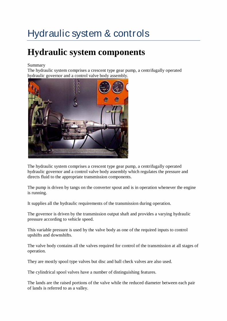
Hydraulic system & controls Hydraulic system components Summary The hydraulic system comprises a crescent type gear pump, a centrifugally operated hydraulic governor and a control valve body assembly.
The hydraulic system comprises a crescent type gear pump, a centrifugally operated hydraulic governor and a control valve body assembly which regulates the pressure and directs fluid to the appropriate transmission components.
The pump is driven by tangs on the converter spout and is in operation whenever the engine is running.
It supplies all the hydraulic requirements of the transmission during operation.
The governor is driven by the transmission output shaft and provides a varying hydraulic pressure according to vehicle speed.
This variable pressure is used by the valve body as one of the required inputs to control upshifts and downshifts.
The valve body contains all the valves required for control of the transmission at all stages of operation.
They are mostly spool type valves but disc and ball check valves are also used.
The cylindrical spool valves have a number of distinguishing features.
The lands are the raised portions of the valve while the reduced diameter between each pair of lands is referred to as a valley.

The face of each land is machined square and sharp to the land diameter and some valves may have a stem or extension on one end to locate a regulating or return spring or to limit valve travel.
The sharp corners on the lands prevent the entry of dirt particles and also give the valve a self-cleaning action as it moves back and forth in the bore.
As there is only a very small clearance between the lands and the bore for each valve, they must be handled with care to avoid possible damage.
Spool valves Summary The valve body contains spool valves which can be positioned manually or by hydraulic pressure or by springs.
Spool valves can be positioned manually, or by springs, or by pressure, and in many applications have lands of different diameters.
In this example, the different diameters result in a larger face area on land 1 than on land 2.
This is known as a differential area and when fluid under pressure enters at port B, this differential area creates a differential force.
This moves the valve to the left since the force acting on land 1 is greater than the force on land 2. Alternatively, the valve could be moved by admitting fluid at port C.
In both cases the valve movement allows previously blocked fluid at D to flow between lands 3 and 4 to exhaust at E or to pass to some other part of the system. If fluid pressure is removed from C the valve will remain stationary.
Even if fluid is admitted at port A, no movement can occur as the areas on lands 2 and 3 are equal and both generate an equal force.

The valve can only be moved back to its original position by introducing spring pressure or fluid pressure on the left hand side of land 1.
Regulating or flow control valves Summary Spool valves can be regulating valves or flow control valves. Regulating valves regulate fluid pressure in the system.
The valves can be divided into two groups.
Pressure regulating valves, and those that direct flow and pressure are flow control valves.
Spool type valves are more suitable for pressure regulation in automatic transmissions as variable pressures must be provided.
In this regulating valve, the valve spring is compressed when the pump or supply pressure becomes high enough.
The larger land then uncovers an exhaust port to maintain a regulated output pressure.
Similarly with this regulating valve in a fluid circuit, the valve is forced downwards against its spring until it begins to uncover a port leading to another part of the circuit.
Since the port is not fully uncovered, there is a restriction to flow and this causes a pressure drop across it.
The pressure of the fluid in this part of the circuit is now less than the pressure of the fluid being supplied.
If the port was fully uncovered, then pressures on both sides of the valve would become equal.
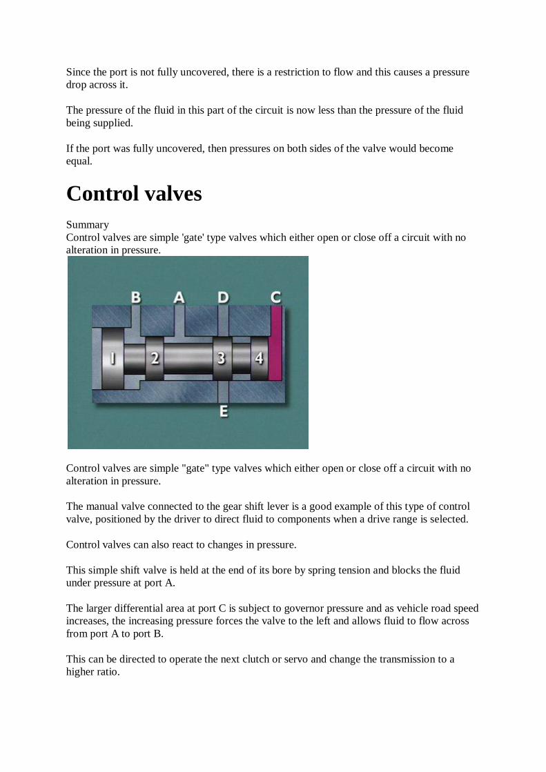
Control valves Summary Control valves are simple 'gate' type valves which either open or close off a circuit with no alteration in pressure.
Control valves are simple "gate" type valves which either open or close off a circuit with no alteration in pressure.
The manual valve connected to the gear shift lever is a good example of this type of control valve, positioned by the driver to direct fluid to components when a drive range is selected.
Control valves can also react to changes in pressure.
This simple shift valve is held at the end of its bore by spring tension and blocks the fluid under pressure at port A.
The larger differential area at port C is subject to governor pressure and as vehicle road speed increases, the increasing pressure forces the valve to the left and allows fluid to flow across from port A to port B.
This can be directed to operate the next clutch or servo and change the transmission to a higher ratio.

As road speed falls and governor pressure diminishes, the spring moves the valve back to cut off the fluid supply and the transmission downshifts.
Orifices Summary Orifices can be used in hydraulic circuits to restrict fluid flow for timing purposes or to prevent valve fluctuations.
Orifices are often used in conjunction with spool valves to restrict fluid flow for timing purposes or to prevent valve fluctuations.
The orifice is designed to prevent sudden or undue movement of a valve.
In this basic primary regulator valve the orifice is in the circuit leading to the large differential spool area.
The build up of line pressure from the pump acts via the orifice to move the valve against the spring force.
This uncovers the exhaust port to release excess fluid and allows fluid at a controlled line pressure to pass to the rest of the hydraulic system.
The pressure is determined by the tension of the spring but pressure fluctuations are reduced since the orifice prevents the valve from reacting quickly and this stabilizes the regulated pressure.

Valve types & functions
Basic valve action Summary The basic action of the valves in the hydraulic system can be summarized in a simple line diagram.
The basic action of the valves in the hydraulic system can be summarized in a simple line diagram.
The primary regulating valve maintains line pressure in the system.
Line pressure is directed to the manual valve and to the throttle valve at all times.
The secondary regulating valve determines the pressure in the converter and in the lubricating circuits.
The manual valve directs line pressure to the shift valves and to the governor valve.
The shift valves direct line pressure to the band and clutch servos.
Governor pressure is directed to one end of the shift valves, while throttle valve pressure is directed to the other end.
Throttle pressure is also directed to the spring end of the primary regulating valve to boost line pressure as required.
Regulator & control valves

Summary The transmission has a number of regulating and control valves which can be readily identified in a hydraulic circuit diagram.
The hydraulic system of the Borg Warner 35 transmission has a number of regulating and control valves. They can be readily identified in a hydraulic circuit diagram.
This valve controls fluid pump output to maintain the required line pressure in the system. Line pressure is the highest pressure in the transmission and all other pressures are derived from line pressure.

This valve reduces line pressure to a low value for use in the torque converter, and in the cooler and lubrication circuits.
This valve is positioned manually by the driver operating the selector lever. It is a control valve which directs line pressure into particular circuits and exhausts fluid from other circuits when each range is selected.
This valve shares a common bore with the downshift or kickdown valve and both are influenced in their position and operation by the downshift cam, connected by a Bowden cable to the accelerator linkage. The throttle valve re-regulates line pressure to a value which is proportional to throttle opening.
The resultant throttle valve, or T.V. pressure, varies from zero at closed throttle to line pressure at full throttle. This pressure is supplied to the spring end of the shift valves to delay

upshifts relative to throttle opening. The wider the throttle opening, the greater the T.V. pressure, and the higher the road speed will be before an upshift will occur.
T.V. pressure is also directed to the spring end of the primary regulating valve to progressively raise line pressure as the accelerator is depressed. This ensures the engaged servos or clutches are securely applied when high torque is being transmitted, and allows the pump to operate at lower pressures at other times. This reduces pumping losses and lowers fuel consumption.
Shift & governor valves Summary The shift valves are control valves supplied with line pressure which is varied by the governor valve depending on road speed. Low speed equals low pressure, high speed equals high pressure.
The 1-2 and 2-3 shift valves are control valves which are supplied with line pressure from the manual valve.
Which either block fluid or allow it to flow at prevailing line pressure to a clutch or band servo.
Their position and movement is determined by a spring plus T.V. pressure acting at one end, opposed by governor pressure acting at the other end.
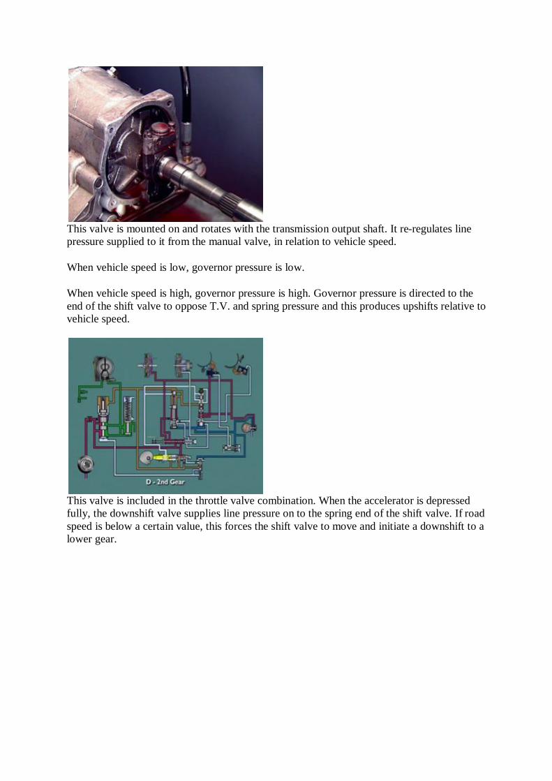
This valve is mounted on and rotates with the transmission output shaft. It re-regulates line pressure supplied to it from the manual valve, in relation to vehicle speed.
When vehicle speed is low, governor pressure is low.
When vehicle speed is high, governor pressure is high. Governor pressure is directed to the end of the shift valve to oppose T.V. and spring pressure and this produces upshifts relative to vehicle speed.
This valve is included in the throttle valve combination. When the accelerator is depressed fully, the downshift valve supplies line pressure on to the spring end of the shift valve. If road speed is below a certain value, this forces the shift valve to move and initiate a downshift to a lower gear.

This valve is in the circuit to the release side of the front band servo. It is a timing device which correlates the release of the front band and the application of the rear clutch when a 2-3 upshift is made at higher road speeds. Conversely it correlates the release of the rear clutch and the re-application of the rear band when a 3-2 downshift is made under similar conditions.
This valve is provided to make line pressure and throttle pressure sensitive to road speed and ensures these pressures are cut-back at higher road speeds to allow smooth upshifts to take place. It also moderates the increase in line pressure produced by wide throttle openings during stall or upshift conditions.
The high throttle pressures produced at these times raises line pressure to a very high value since the throttle pressure is applied to the spring end of the primary regulating valve.
Modulator pressure is applied to the opposite end of the regulating valve to counteract this and moderate its influence.
Pressure regulation
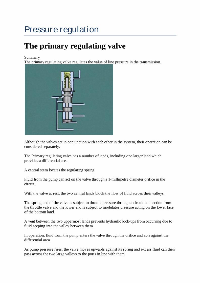
The primary regulating valve Summary The primary regulating valve regulates the value of line pressure in the transmission.
Although the valves act in conjunction with each other in the system, their operation can be considered separately.
The Primary regulating valve has a number of lands, including one larger land which provides a differential area.
A central stem locates the regulating spring.
Fluid from the pump can act on the valve through a 1-millimetre diameter orifice in the circuit.
With the valve at rest, the two central lands block the flow of fluid across their valleys.
The spring end of the valve is subject to throttle pressure through a circuit connection from the throttle valve and the lower end is subject to modulator pressure acting on the lower face of the bottom land.
A vent between the two uppermost lands prevents hydraulic lock-ups from occurring due to fluid seeping into the valley between them.
In operation, fluid from the pump enters the valve through the orifice and acts against the differential area.
As pump pressure rises, the valve moves upwards against its spring and excess fluid can then pass across the two large valleys to the ports in line with them.

The result is an initial regulation of line pressure to about 450 kilopascals at idling speed.
This line pressure is directed to the manual valve and to the throttle valve at all times,
When "D" is selected, line pressure is also directed to the front clutch, to the 1-2 shift valve and to the governor.
The excess fluid passing across the valleys is directed to the secondary regulating valve and to the converter.
Fluid from the lower port of the primary regulator valve acts on the end face of the secondary regulating valve and raises it against its spring.
The valve movement firstly uncovers a port to the lubrication circuit for the rear end of the gear train and secondly an exhaust port leading back to the pump inlet.
The exhaust bleed off stabilizes fluid pressure in the lubrication and converter circuits to within acceptable limits of approximately 100 to 200 kilopascals.
Line pressure variation Summary Throttle valve pressure is derived from line pressure and is applied to the spring end of the primary regulating valve to increase line pressure relative to accelerator depression.
Line pressure can be varied according to accelerator position and to vehicle speed that requires additional control over the primary regulating valve.
High line pressure is required to hold a band or apply a clutch securely to prevent slippage when the accelerator is depressed and a high torque is transmitted.
On the other hand, once the vehicle is moving and the transmission is up-shifting, less torque is being transmitted and so a lower value of line pressure will be adequate.
Applying throttle pressure to the spring end of the primary regulating valve lifts line pressure. Applying modulator pressure to the opposite end reduces it.
Line pressure is supplied to the throttle valve at all times and throttle pressure is derived from it.
At closed throttle, the throttle valve is at rest and line pressure is blocked off by a land. Throttle pressure is zero.
When the accelerator is depressed, the movement is transferred through the kickdown valve and its spring to open the throttle valve and the land uncovers the line pressure port.
Fluid at line pressure is now metered into the throttle valve circuits and a T.V. pressure is quickly established.
This extends through the orifice to the valve reaction area and this tends to close the valve against the spring force and minimizes pressure fluctuations.
A balance is established to produce a T.V. pressure which is relative to the accelerator position. T.V. pressure can vary from 0 to approximately 1200 kilopascals.
T.V. pressure is directed back through the circuits to the spring end of the primary regulator valve to assist the spring in opposing the force of fluid coming from the pump and acting on the valves' differential area via the orifice.
Consequently T.V. pressure holds the primary regulator valve down to increase line pressure relative to the extent that the accelerator is depressed.
This ensures clutch and band apply forces will be maintained in step with accelerator position.
Modulator valve pressure Summary Modulator valve pressure is directed to the lower end of the primary regulating valve, opposite to the regulating spring.
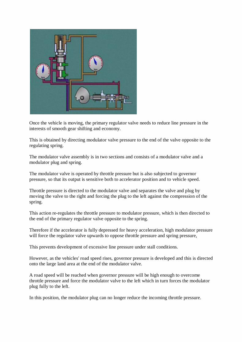
Once the vehicle is moving, the primary regulator valve needs to reduce line pressure in the interests of smooth gear shifting and economy.
This is obtained by directing modulator valve pressure to the end of the valve opposite to the regulating spring.
The modulator valve assembly is in two sections and consists of a modulator valve and a modulator plug and spring.
The modulator valve is operated by throttle pressure but is also subjected to governor pressure, so that its output is sensitive both to accelerator position and to vehicle speed.
Throttle pressure is directed to the modulator valve and separates the valve and plug by moving the valve to the right and forcing the plug to the left against the compression of the spring.
This action re-regulates the throttle pressure to modulator pressure, which is then directed to the end of the primary regulator valve opposite to the spring.
Therefore if the accelerator is fully depressed for heavy acceleration, high modulator pressure will force the regulator valve upwards to oppose throttle pressure and spring pressure,
This prevents development of excessive line pressure under stall conditions.
However, as the vehicles' road speed rises, governor pressure is developed and this is directed onto the large land area at the end of the modulator valve.
A road speed will be reached when governor pressure will be high enough to overcome throttle pressure and force the modulator valve to the left which in turn forces the modulator plug fully to the left.
In this position, the modulator plug can no longer reduce the incoming throttle pressure.

This means that the undiminished throttle pressure will now exist in the modulator circuit and will be applied to the lower end of the primary regulating valve.
The pressure moves the regulator valve upwards to suitably reduce line pressure for a smooth upshift, about to take place.
This reduction in line pressure is referred to as the "cut-back" point.
At the same time as governor pressure moves the modulator valve to the left, it also allows throttle pressure to pass between the modulator valve lands and into a circuit leading back to the smallest reaction area at the end of the throttle valve.
This pressure, acting through the orifice in the circuit, helps to move the throttle valve to the left against its regulating spring.
This reduces the initial T.V. pressure established in the throttle pressure circuit, and in turn, further reduces line pressure.
The governor Summary The governor is in two sections comprising the governor valve and its spring, and a bob-weight retained by a 'C' clip.
The governor is in two sections comprising the governor valve and its spring and a bob-weight retained by a "C" clip.
It operates by centrifugal force in two stages.
In the first stage at lower road speeds, the bob-weight and valve can be considered as forming one unit.

Rotation of the governor throws out the bob-weight and this causes the valve to uncover the line pressure supply port so that fluid under pressure flows through the port and exerts a thrust on the face of the valve.
This thrust increases until it is capable of closing the valve against the opposition of the centrifugal force.
The action of the valve produces a fluid pressure at the outlet which is proportional to the force acting on the bob-weight.
Any increase in speed will cause these events to be repeated but as the speed is greater the pressure required to close the valve must also be greater.
For any given value of line pressure, the result is a governor pressure which increases with speed.
The second stage starts when the bob-weight stop contacts the body.
From this point onwards, the balance between the opening and closing of the valve is achieved by the centrifugal effect on the valve and the fluid acting on the pressure face of the valve.
Governor pressure Summary Upward movement of the 1-2 shift valve allows fluid at line pressure to flow to the apply side of the front band servo.
The governor pressure developed acts on the end of the 1-2 shift valve and as road speed increases it becomes high enough to overcome the opposing forces of the spring and throttle pressure.
The shift valve assembly moves upwards and allows line pressure to pass into the circuit to the apply side of the front band servo.

The transmission is now in second gear.
Once the 1-2 upshift has taken place, the differential area is no longer effective.
This means a 2-1 downshift cannot take place at the same road speed as the upshift since governor pressure must drop to a lower value to allow the valve to move back to the 1st gear position.
For downshifts to occur, the vehicle speed must be somewhat less than the speed at which upshifts occur.
The shift spread provided prevents the transmission from "hunting" up and down between two ratios and is referred to as shift speed "Hysteresis".
Kickdown pressure Summary Kickdown pressure is supplied to the spring end of the 1-2 shift valve to force a 2-1 downshift under 'kickdown' conditions.
Additional force can be provided to force a 2-1 downshift under "kickdown" conditions.
This is provided by the kickdown portion of the kickdown/throttle valve combination.
When the accelerator is fully depressed, the kickdown valve closes off the exhaust from the kickdown circuit and also forces the throttle valve to the end of its bore.
In this position, the throttle valve can no longer regulate the incoming line pressure and throttle pressure now becomes equal to line pressure and passes into the kickdown circuit leading to the kickdown port at the 1-2 shift valve.
Fluid passes across the valley area and onto the spring end of the plunger.

The force provided overcomes governor pressure and moves the shift valve back to the 1st gear position.
This releases the front band by opening its apply circuit and exhausting the apply fluid back to the pan.
However, as road speed rises governor pressure will increase and since it is acting on the large differential area on the bottom land, will eventually become high enough to force the valve upwards and overcome kickdown pressure.
This keeps engine RPM within safe limits in the automatic range.

Flow control
Gear position 1 Summary When gear lever position 1 is selected, the manual valve directs fluid at line pressure to the front clutch and to the rear band servo.
When 1 is selected, the manual valve supplies line pressure not only onto the differential area but also through a separate circuit to apply the rear band.
The application of the rear band provides engine braking on overrun.
This circuit passes through the bottom valley area of the valve and acts on the large bottomland to hydraulically lock the shift valve down.
Governor pressure cannot force an upshift, regardless of its value and the transmission remains in 1st gear until the lever is moved to 2 or to D, when an upshift can occur.
The rear band is inoperative whenever D is selected because the rear band is then open to exhaust at the manual valve.
Similarly, once the transmission has upshifted into 2nd gear, the rear band circuit is then open to exhaust at the shift valve.
When the transmission lever is placed in position 2, line pressure is directed to the front clutch, as in position D and to the governor and to the 1-2 shift valve.
The vehicle will move off in 1st gear and will change up to 2nd gear as soon as governor pressure becomes high enough to move the shift valve upwards and allow fluid to pass to the apply side of the front servo.

No further upshifts can take place since no line pressure is supplied to the 2-3 shift valve.
Even though the valve moves upwards under the influence of governor pressure, it is not controlling any fluid flow and no changes can occur.
1-2 shift valve Summary The 1-2 shift valve has a lower valve section and an upper section plug and spring.
When "D" range is selected, the manual valve allows fluid at line pressure to be directed to the front clutch, which will remain applied in all forward gears.
Fluid in this circuit is also directed to the governor and to the 1-2 shift valve where it is blocked at a differential area.
A separate circuit from the manual valve directs line pressure to a differential area of the 2-3 shift valve and this is held in the downshifted or 2 position by a combination of the differential force and the spring force.
The 1-2 shift valve is in two sections. The shift valve itself is the lower section and this is held in its downmost position by a combination of the differential force and by the upper section plunger and spring.
In addition, as soon as the accelerator is depressed, throttle pressure will be directed to assist in holding the valves in the downshifted position and thus ensuring that their movement will be influenced by accelerator position.
The line pressure supplied to the governor will be re-regulated by the governor to governor pressure when the vehicle is in motion and this governor pressure will be directed to the large land areas at the bottom end of the 1-2 and 2-3 shift valves.
2-3 shift valve assembly

Summary The 2-3 shift valve assembly consists of the shift valve, its spring and a throttle pressure regulating plug.
The 2-3 shift valve assembly consists of the shift valve, its spring, and a throttle pressure regulating plug.
In D range, line pressure is supplied from the manual valve onto a differential area and this assists the spring in holding the valve down against governor pressure.
In this position, the rear clutch apply and front band release circuit is open to exhaust.
With the vehicle in motion in 2nd gear and at a minimum throttle opening, throttle pressure is applied to the top of the regulating plug but under these conditions will not be at a high enough value to move it downwards.
Since the only forces opposing governor pressure are the spring, and the line pressure acting on the differential area land, a 2-3 upshift will take place at a relatively low vehicle speed.
With the vehicle in motion in 2nd gear and at higher throttle openings, higher throttle pressure moves the plug down towards the shift valve and this re-regulates the throttle pressure into a lower value so that it can act on the top land of the shift valve.
This assists the spring to control the shift points relative to accelerator position at lower vehicle speeds.
As soon as governor pressure becomes high enough to overcome the combined opposing forces, the valve upshifts into the top gear position and fluid at line pressure can flow across to apply the rear clutch.
At the same time fluid passes through the servo orifice control valve to the release side of the front band servo and this means the front clutch and the rear clutch are now the only components being applied, providing top gear.

The servo orifice control valve Summary The servo orifice control valve is a shuttle valve which can be positioned at rest by a spring or can be moved by governor pressure.
The servo orifice control valve acts as a timing device to prevent engine flare at wide throttle openings on a 2-3 upshift and conversely to prevent the transmission becoming "tied-up" or being momentarily in two gears during a 3-2 downshift.
It is a shuttle valve which can be positioned at rest by a spring to allow unrestricted fluid flow, or can be moved by governor pressure to insert a restricting orifice in the front band servo release circuit.
At low vehicle speeds, governor pressure is not high enough to move the valve and when the 2-3 upshift occurs, fluid flows unrestricted to the release side of the front servo.
Since this type of shift will occur at light throttle openings, the rapid clutch and band actuation does not cause engine flare.
With wider throttle openings, vehicle speeds will be higher before an upshift occurs and governor pressure will have built up sufficiently to move the valve, so that the fluid must now pass through the orifice.
This slows up the release of the front band and thus ensures the rear clutch is fully applied and able to transmit torque as the band comes off.
This prevents engine flare from occurring.
Similarly on a downshift at high vehicle speeds, the orifice slows up the release of fluid from the release side of the front servo and therefore the re-application of the front band.
This ensures the rear clutch comes off as the band is applied and prevents a lock-up condition in the transmission.

3-2 kickdown Summary Governor pressure determines whether or not a 3-2 kickdown downshift can be made.
When a 3-2 kickdown downshift is required, the fully depressed throttle prevents the throttle valve from regulating the incoming line pressure and throttle pressure becomes equal to line pressure.
Fluid at line pressure passes through the kickdown valve and acts on the top land of the 2-3 shift valve.
If road speed and therefore governor pressure is low enough, then the force provided will move the valve down and effect a change to 2nd gear.
If a change does take place, then as road speed increases, governor pressure will eventually overcome the opposing forces and move the shift valve upwards, even if the accelerator remains fully depressed.
If road speed is above a certain minimum, then a downshift will be denied, preventing the engine from over-revving.
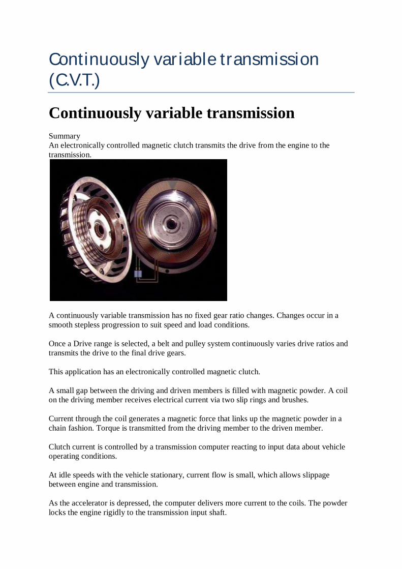
Continuously variable transmission (C.V.T.)
Continuously variable transmission Summary An electronically controlled magnetic clutch transmits the drive from the engine to the transmission.
A continuously variable transmission has no fixed gear ratio changes. Changes occur in a smooth stepless progression to suit speed and load conditions.
Once a Drive range is selected, a belt and pulley system continuously varies drive ratios and transmits the drive to the final drive gears.
This application has an electronically controlled magnetic clutch.
A small gap between the driving and driven members is filled with magnetic powder. A coil on the driving member receives electrical current via two slip rings and brushes.
Current through the coil generates a magnetic force that links up the magnetic powder in a chain fashion. Torque is transmitted from the driving member to the driven member.
Clutch current is controlled by a transmission computer reacting to input data about vehicle operating conditions.
At idle speeds with the vehicle stationary, current flow is small, which allows slippage between engine and transmission.
As the accelerator is depressed, the computer delivers more current to the coils. The powder locks the engine rigidly to the transmission input shaft.

With the engine off, or the selector in Park or Neutral, reverse direct current sent to the coil de-magnetizes the clutch powder and releases the clutch completely.
Drive or reverse Summary A belt and pulley system continuously varies the ratios and transmits the drive to the final drive gears.
Forward or reverse motion of the vehicle is obtained by placing the selector lever in Drive or Reverse.
In Drive, a synchronizer assembly connects the magnetic clutch directly to the primary pulley of the variable transmission.
In Reverse, the drive is transmitted through a reverse idler. It changes the direction of rotation of the primary pulley, and the transmission.
A steel vee belt connects the primary pulley to the secondary. The pulleys are split to allow their contact radius or groove width to be varied.
Hydraulic pressure from an engine driven pump, and a computerized hydraulic-control system, moves one side of each pulley inward or outward.
This widens or narrows the pulleys, but the vee belt stays taut at all times.
In a widened pulley, the belt rides down to the bottom of the groove.
When the pulley is narrowed, it rides up to the top.
This creates different size pulleys, which act like gears of different sizes, to provide varying gear ratios.
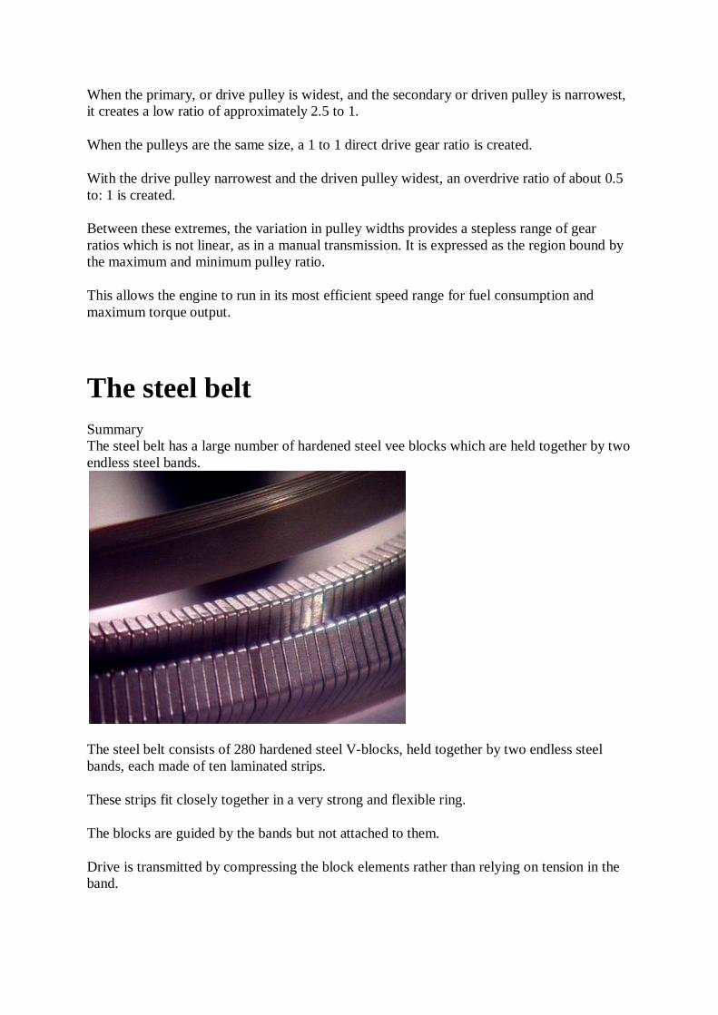
When the primary, or drive pulley is widest, and the secondary or driven pulley is narrowest, it creates a low ratio of approximately 2.5 to 1.
When the pulleys are the same size, a 1 to 1 direct drive gear ratio is created.
With the drive pulley narrowest and the driven pulley widest, an overdrive ratio of about 0.5 to: 1 is created.
Between these extremes, the variation in pulley widths provides a stepless range of gear ratios which is not linear, as in a manual transmission. It is expressed as the region bound by the maximum and minimum pulley ratio.
This allows the engine to run in its most efficient speed range for fuel consumption and maximum torque output.
The steel belt Summary The steel belt has a large number of hardened steel vee blocks which are held together by two endless steel bands.
The steel belt consists of 280 hardened steel V-blocks, held together by two endless steel bands, each made of ten laminated strips.
These strips fit closely together in a very strong and flexible ring.
The blocks are guided by the bands but not attached to them.
Drive is transmitted by compressing the block elements rather than relying on tension in the band.

Each block leaving the primary pulley pushes the blocks ahead of it, to the secondary pulley where the bands keep the blocks in contact with the pulley faces.
The blocks are in compression on the drive side, and float loosely along the laminated bands on the return side.
The large number of blocks in contact with the pulleys keeps surface pressures low, allowing high torque to be transmitted.
The belt is lubricated by transmission fluid sprayed directly onto it at high pressure.
Secondary pulley shaft Summary Placing the selector lever in 'D' provides a normal driving mode, from starting off to maximum speed. Selecting 'D' provides engine braking on overrun.
The secondary pulley shaft is splined to a helical reduction drive gear. It meshes with a similar reduction driven gear, splined to the final-drive pinion shaft.
The final-drive pinion meshes with the final-drive ring gear to transmit the drive to the differential case.
Selecting "D" provides a normal driving mode, from start off to maximum speed.
Speed change occurs between 1600 and 4000 RPM depending on whether acceleration is gradual or rapid.
At cruising speed, when pressure on the accelerator is reduced, the pulley ratio is at a maximum and the transmission is in overdrive.
If the accelerator is depressed while cruising, the pulley ratio shifts to minimum and vehicle speed rises quickly.

In the "Ds" position, ratio changes can occur only in the higher zone of the speed change region.
In Reverse, the pulleys are locked in a low ratio position. No speed ratio changes take place.
In Park, the secondary pulley is mechanically locked to the transmission case.

Automatic transmissions procedures
Checking automatic transmission fluid Summary A correct fluid level is critical to effective and efficient operation. If the level is too high, it will cause the fluid to churn and aerate, causing air bubbles that can trap heat and make the fluid run hotter. This can lead to early failure of bearings or gears. The objective of this procedure is to show you how to check and adjust transmission and transaxle fluid for automatic transmissions.
Part 1. Preparation and safety
Objective
Check and adjust transmission and transaxle fluid for automatic transmissions.
Personal safety
Whenever you perform a task in the workshop you must use personal protective clothing and equipment that is appropriate for the task and which conforms to your local safety regulations and policies. Among other items, this may include:
Work clothing - such as coveralls and steel-capped footwear Eye protection - such as safety glasses and face masks Ear protection - such as earmuffs and earplugs Hand protection - such as rubber gloves and barrier cream Respiratory equipment - such as face masks and valved respirators
If you are not certain what is appropriate or required, ask your supervisor.

Safety check
Do not put your finger into the filler plug opening to check the fluid level whenever the transmission is rotating.
If the vehicle has been driven prior to checking the fluid level, the fluid could be very hot. When you remove the filler plug this hot fluid may run out. Make sure you do not burn yourself on this hot fluid.
Make sure that you understand and observe all legislative and personal safety procedures when carrying out the following tasks. If you are unsure of what these are, ask your supervisor.
Points to note
You will need to refer to the owner's manual to find out where to check the oil level. A correct fluid level is critical to effective and efficient operation. If the level is too
high, it will cause the fluid to churn and aerate, causing air bubbles that can trap heat and make the fluid run hotter. This can lead to early failure of bearings or gears.
If the vehicle is not level when taking a reading, you may not get an accurate result. A low fluid level can cause as much of a problem as a high level. Air can enter the
system and heat generation can burn vital internal components. Some automatic fluids expand quite a lot when they get hot, so it is extremely
important to ensure the fluid level is correct at all temperatures. In the unlikely event that the fluid is over full when checking the automatic
transmission system, and it has not been simply over filled at the time of service, it could indicate that water has entered the transmission through the transmission breather system. If this is the case, then the transmission fluid should be replaced.
Color and condition of automatic transmission fluid: o Clean, uncontaminated fluid has a pinkish or reddish color o Fluid that has been overheated turns darkish brown or black o A white, milky appearance can mean the engine coolant is leaking into the
transmission
Part 2: Step-by-step instruction
1. Prepare the vehicle Warm up the fluid by idling or driving the vehicle. Generally, automatic transmission designs use a dipstick to determine the correct transmission fluid level. Locate the dipstick and remove it, wipe it clean, examine the level marks and then insert it again. Refer to the shop manual to see what position the gear selector should be in, as different manufacturers specify different gear positions.
2. Check the fluid level Apply the foot brake and move the transmission selector through all the gear selections. This will allow all the cavities in the transmission to fill with new fluid, and check the fluid level in the specified condition by removing the dipstick and observing the fluid level on the dipstick. Adjust the level by adding the approved lubricant as necessary.
Changing transmission fluid & filter Summary The objective of this procedure is to show you how to change automatic transmission/transaxle fluid. You will need to refer to the owner's manual for the specified intervals for lubricant servicing. Selecting and using the correct type and grade of lubricant is critical. The wrong selection can lead to premature failure of the internal components.
Part 1. Preparation and safety
Objective
Change automatic transmission/transaxle fluid.

Personal safety
Whenever you perform a task in the workshop you must use personal protective clothing and equipment that is appropriate for the task and which conforms to your local safety regulations and policies. Among other items, this may include:
Work clothing - such as coveralls and steel-capped footwear Eye protection - such as safety glasses and face masks Ear protection - such as earmuffs and earplugs Hand protection - such as rubber gloves and barrier cream Respiratory equipment - such as face masks and valved respirators
If you are not certain what is appropriate or required, ask your supervisor.
Safety check
Do not put your finger into the filler plug opening to check the fluid level if the transmission is rotating, either by the engine or by some person turning the drive wheels.
If the vehicle has been driven prior to checking the fluid level, the fluid could be very hot. Be careful not to burn yourself on this hot fluid.
Make sure that you understand and observe all legislative and personal safety procedures when carrying out the following tasks. If you are unsure of what these are, ask your supervisor.
Points to note
You will need to refer to the owner's manual for the specified intervals for lubricant servicing.
If the engine is cold, the vehicle may need to be driven a short distance to bring the oil to normal operating temperature. Any contaminants in the fluid will flow out more readily with a warm to hot fluid.

Selecting and using the correct type and grade of lubricant is critical. The wrong selection can lead to premature failure of the internal components.
A correct fluid level is critical to effective and efficient operation. If the level is too high, it will cause the fluid to churn and aerate, causing air bubbles that can trap heat and make the fluid run hotter. This can lead to early failure of bearings or gears.
A low fluid level can cause as many problems as a high fluid level. Air can enter the system and heat generation can burn vital internal components.
Part 2: Step-by-step instruction
1. Prepare to drain lubricant Warm up the transmission fluid by idling or driving the vehicle. Raise the vehicle, and ensuring that it is level and stable, do a visual inspection for leaks from the transmission. Most transaxles have drain plugs fitted to them that are easily accessible. However, some require that a housing be removed in order to drain the oil. Other types do not have drain plugs, and require a suction pump to draw out the lubricant by hand from the filling point. Consult the shop manual for correct procedures for draining the fluid on the vehicle you are working on. Be careful because the lubricant can be hot enough to burn.
2. Drain lubricant using drain plug Locate the position of the drain plug and remove any guard covers if necessary. Select the correct wrench and loosen the plug. Position a large diameter drain pan under the transmission, clean the plug, and then remove it.
3. Draining auto transmission without drain plug In the case of an automatic transmission, if there is no drain plug, loosen all the transmission pan bolts, with the correct wrench and remove all but three, the minimum necessary to hold the pan in place. Fluid will flow into the drain pan. Once the fluid stops flowing from the bolt holes, support the transmission pan with one hand, and remove the remaining bolts to drain the remaining oil.
4. Examine lubricant and pan Look for metal in the fluid, which looks like shiny particles or flakes. If the transmission has been overfilled during service, it could have caused internal damage to components. Also inspect the transmission pan and the residue in it. A small amount of metal deposits is normal, but a build-up could signal excessive transmission wear. If you find larger pieces of metal or clutch material that looks a lot like brake lining material in the case of an automatic transmission, have your supervisor come and inspect it. It is good practice to keep these larger particles in case the owner wants to see them.
5. Clean auto transmission oil pan gasket and filter screen With an automatic transmission, carefully remove the oil pan gasket. Don’t use a sharp tool that could damage the sealing surface. Clean the pan with a lint-free cloth, and remove the transmission filter. Filters and screens may be held in place by several screws of varying sizes. Be careful to note any size differences of the screws so you can reinstall them in the correct position. If you have a paper or cotton filter in the transmission, it must be changed every time you change the transmission fluid. Metal filters can be cleaned with solvent or a spray cleaner and reused after air-drying.
6. Replace auto transmission filter and oil pan gasket Install the new filter on the valve body as described in the shop manual. Place the new

gasket on the sealing surface of the fluid pan. Apply the manufacturer’s recommended sealant to the gasket if needed.
7. Clean and re-install drain plug Replace the transmission or sump pan, and tighten the bolts to the manufacturer-specified torque. Over tightening the bolts may damage the gasket and/or the sealing surfaces. After the lubricant is completely drained, clean the drain plug. Put the drain plug back with a new washer. Use a torque wrench to make sure the torque is correct.
8. Pump in new lubricant Check the shop manual’s lubrication guide for the correct replacement fluid specification and the correct quantity. If the filling location is under the hood, you will need to lower the vehicle. Clean the nozzle of a lubricant pump with a clean lint free rag or paper towel. Use the pump to put new transmission oil into the filler hole or dipstick tube opening. Pause for a few seconds after each pump, to give the lubricant time to flow to the bottom. Stop when the lubricant reaches the bottom of the filler plug hole, or to the top of the cold mark on the dipstick.
9. Move through the gears (auto) In the case of an automatic transmission, start the engine. Apply the foot brake, and move the transmission selector through all the gear selections. This will allow all the cavities in the transmission to fill with new fluid. Place the transmission in the correct gear for fluid checking.
10. Check the new fluid level Check the new fluid level. Adjust if necessary and replace the dipstick or filler plug.


![Torque Converter Voith Torque Converter[1]](https://static.fdocuments.in/doc/165x107/55cf992e550346d0339c0bc5/torque-converter-voith-torque-converter1.jpg)


