TORQUE-ARM II™ Speed Reducers Ratios 5, 9, 15, 25, and 40:1
32
1 Installation and Parts Replacement Manual For Dodge ® TORQUE-ARM II™ Speed Reducers Ratios 5, 9, 15, 25, and 40:1 TA0107L TA1107H TA2115H TA3203H TA4207H TA5215H TA6307H TA7315H TA8407H TA9415H TA10507H TA12608H WARNING: Because of the possible danger to person(s) or property from accidents which may result from the improper use of products, it is important that correct procedures be followed. Products must be used in accordance with the engineering information specified in the catalog. Proper installation, maintenance and operation procedures must be observed. The instructions in the instruction manuals must be followed. Inspections should be made as necessary to assure safe operation under prevailing conditions. Proper guards and other suitable safety devices or procedures, as may be desirable, or as may be specified in safety codes should be provided, and are neither provided by Rockwell Automation, nor are the responsibility of Rockwell Automation. This unit and its associated equipment must be installed, adjusted and maintained by qualified personnel who are familiar with the construction and operation of all equipment in the system and the potential hazards involved. When risks to persons or property may be involved, a holding device must be an integral part of the driven equipment beyond the speed reducer output shaft. Rockwell Automation – Dodge/Reliance / P.O. Box 499 / 6040 Ponders Court / Greenville, SC 29602-0499 USA Tel: 864-297-4800 / Fax: 864-281-2433 / E-mail: [email protected] © 2000 Rockwell Automation Dodge ® and TORQUE-ARM II™ are registered Trademarks of Rockwell Automation. Printed in USA 11/00 499385
Transcript of TORQUE-ARM II™ Speed Reducers Ratios 5, 9, 15, 25, and 40:1
1
Installation and Parts Replacement ManualFor
Dodge® TORQUE-ARM II™Speed Reducers
Ratios 5, 9, 15, 25, and 40:1
TA0107LTA1107HTA2115HTA3203HTA4207HTA5215H
TA6307HTA7315HTA8407HTA9415HTA10507HTA12608H
WARNING: Because of the possible danger to person(s) or property from accidents which may result from the improper use of products, itis important that correct procedures be followed. Products must be used in accordance with the engineering information specified in thecatalog. Proper installation, maintenance and operation procedures must be observed. The instructions in the instruction manuals mustbe followed. Inspections should be made as necessary to assure safe operation under prevailing conditions. Proper guards and othersuitable safety devices or procedures, as may be desirable, or as may be specified in safety codes should be provided, and are neitherprovided by Rockwell Automation, nor are the responsibility of Rockwell Automation. This unit and its associated equipment must beinstalled, adjusted and maintained by qualified personnel who are familiar with the construction and operation of all equipment in thesystem and the potential hazards involved. When risks to persons or property may be involved, a holding device must be an integral partof the driven equipment beyond the speed reducer output shaft.
Rockwell Automation – Dodge/Reliance / P.O. Box 499 / 6040 Ponders Court / Greenville, SC 29602-0499 USATel: 864-297-4800 / Fax: 864-281-2433 / E-mail: [email protected]
© 2000 Rockwell AutomationDodge® and TORQUE-ARM II™ are registered Trademarks of Rockwell Automation.
Printed in USA 11/00 499385

2
CONTENTS
TORQUE-ARM II REDUCER INSTALLATION………………..…... 3
TORQUE-ARM II BUSHING INSTALLATION………...…………… 4
LUBRICATION…………………………………………………………. 6
GUIDELINES FOR TORQUE-ARM II REDUCERLONG-TERM STORAGE……………………………………………... 8
OIL VISCOSITY EQUIVALENCY CHART………………………….. 9
COOLING FAN INSTALLATION ……………………………………. 10
BACKSTOPS…………………...……………………………………… 12
MOTOR MOUNTS………...…………………………………………… 13
TORQUE-ARM II BELT GUARD INSTALLATION………………… 17
SCREW CONVEYOR ADAPTER ASSEMBLY………...………….. 19
DRIVESHAFT REMOVAL ………...…………………………………. 19
REPLACEMENT OF PARTS………………...………………………. 20
REPLACEMENT PART AND KIT NUMBERS………...…………… 22
TORQUE-ARM II REDUCER SECTION VIEWS…………………… 25
DETAILED PARTS LIST……………………………………………… 27
ACTUAL RATIOS……………………………………………………… 32

3
INSTALLATION1. Use lifting bracket to lift reducer.
2. Determine the running positions of the reducer. (See Fig. 1)Note that the reducer is supplied with 6 plugs; 4 around thesides for horizontal installations and 1 on each face for verticalinstallations. These plugs must be arranged relative to therunning positions as follows:
Horizontal Installations - Install the magnetic drain plug in thehole closest to the bottom of the reducer. Throw away the tapethat covers the filter/ventilation plug in shipment and install plugin topmost hole. Of the 2 remaining plugs on the sides of thereducer, the lowest one is the minimum oil level plug.
Vertical Installations - Install the filter/ventilation plug in thehole provided in the upper face of the reducer housing asinstalled. If space is restricted on the upper face, install the ventin the highest hole on the side of the reducer per Figure 1.Install a plug in the hole in the bottom face of the reducer. Donot use this hole for the magnetic drain plug. Of the remainingholes on the sides of the reducer, use the plug in the upperhousing half for the minimum oil level plug.
Figure 1 – Mounting Positions
VERTICAL MOUNTING
POSITION AHORIZONTAL MOUNTING
12
3
4
4 3
1
2POSITION B
POSITION C POSITION D
POSITION FPOSITION E
5 (NEAR)6 (FAR)
5 (NEAR)6 (FAR)
3
4
12
5 (NEAR)6 (FAR)
3 4
1
2
5 (NEAR)6 (FAR)
1 2
4 (NEAR)3 (FAR)
5
612
5
64 (NEAR)3 (FAR)
Output Speeds Above 15 RPMVent and Plug LocationsMounting
Position 1 2 3 4 5 6Position A Level Plug Drain Vent Plug PlugPosition B Drain Vent Level Plug Plug PlugPosition C Plug Level Vent Drain Plug PlugPosition D Vent Drain Level Plug Plug PlugPosition E Level Plug Plug Drain Vent PlugPosition F Plug Drain Level Plug Plug Vent
Output Speeds 15 RPM and Below �Vent and Plug LocationsMounting
Position 1 2 3 4 5 6Position A Plug Level Drain Vent Plug PlugPosition B Drain Vent Plug Level Plug PlugPosition C Level Plug Vent Drain Plug PlugPosition D Vent Drain Level Plug Plug PlugPosition E Level Plug Plug Drain Vent PlugPosition F Plug Drain Level Plug Plug Vent
� Below 15 RPM output speed, oil level must be adjusted to reach the highestoil level plug. If reducer position is to vary from those shown in Figure 1, eithermore or less oil may be required. Consult Dodge.
The running position of the reducer in a horizontal application isnot limited to the four positions shown in Fig. 1. However, ifrunning position is over 20° in position "B" & "D" or 5° in position"A" & "C", either way from sketches, the oil level plug cannot beused safely to check the oil level, unless during the checking,the torque arm is disconnected and the reducer is swung towithin 20° for position "A" & "C" or 5° for position "B" & "D" ofthe positions shown in Fig. 1. Because of the many possiblepositions of the reducer, it may be necessary or desirable tomake special adaptations using the lubrication filling holesfurnished along with other standard pipe fittings, stand pipesand oil level gauges as required.
3. Mount reducer on driven shaft as follows:
WARNING: To ensure that drive is not unexpectedly started,turn off and lock out or tag power source before proceeding.Remove all external loads from drive before removing orservicing drive or accessories. Failure to observe theseprecautions could result in bodily injury.
For Taper Bushed Reducer: Mount reducer on driven shaftper instruction in Torque-Arm II Bushing Installation section ofthis manual.
4. Install sheave on input shaft as close to reducer as practical.(See Fig. 2)
5. If not using a Dodge Torque-Arm II motor mount, installmotor and V-belt drive so belt will approximately be at rightangles to the centerline between driven and input shaft. (SeeFig. 3) This will permit tightening the V-belt with the torque arm.
6. Install torque arm and adapter plates reusing the reducerbolts. The adapter plates will fit in any position around the inputend reducer.
7. Install torque arm fulcrum on a flat and rigid support so thatthe torque arm will be approximately at right angles to thecenterline through the driven shaft and the torque arm anchorscrew. (See Fig. 4) Make sure that there is sufficient take-up inthe turnbuckle for belt tension adjustment when using V-beltdrive.

4
CAUTION: Unit is shipped without oil. Add proper amount ofrecommended lubricant before operating. Failure to observethis precaution could result in damage to or destruction of theequipment
8. Fill gear reducer with recommended lubricant. See Table 2.
KEEPCLOSE
KEEPCLOSE
INPUTSHAFT
DRIVENSHAFT
Figure 2 – Reducer and Sheave Installation
RIGHT ANGLE ORMAY VARY 30°
V-BELTDRIVE
V-BELTDRIVE MAYBE LOCATEDTO THERIGHT IFDESIRED
Figure 3 – Angle of V-Drive
TORQUEARM MAYBE LOCATEDTO THERIGHT IFDESIRED
RIGHT ANGLE ORMAY VARY 20° IN
TENSION ORCOMPRESSION
TORQUE-ARMAND BELT
TAKE-UP
Figure 4 – Angle of Torque-Arm
TORQUE-ARM II BUSHINGINSTALLATIONWARNING: To ensure that drive is not unexpectedly started,turn off and lock out or tag power source before proceeding.Remove all external loads from drive before removing orservicing drive or accessories. Failure to observe theseprecautions could result in bodily injury.
The Dodge Torque-Arm II Reducer is designed to fit bothstandard and short length driven shafts. The Standard TaperBushings series is designed where shaft length is not a concern.The Short Shaft Bushing series is to be used where the drivenshaft does not extend through the reducer.
Standard Taper Bushings:
1. One bushing assembly is required to mount the reducer onthe driven shaft. An assembly consists of two tapered bushings,bushing screws and washers, two bushing backup plates andretaining rings, and necessary shaft key or keys. The drivenshaft must extend through the full length of the reducer. If thedriven shaft does not extend through the reducer do not use thestandard tapered bushings; instead use the short shaft bushingsas described in the Short Shaft Bushings section that follows.The minimum shaft length, as measured from the end of theshaft to the outer edge of the bushing flange (see Figure 5), isgiven in Table 1.
2. Install one bushing backup plate on the end of the hub andsecure with the supplied retaining ring. Repeat procedure forother side.
3. Place one bushing, flange end first, onto the driven shaft andposition per dimension “A”, as shown in Table 1. This will allowthe bolts to be threaded into the bushing for future bushing andreducer removal.
4. Insert the output key in the shaft and bushing. For easy ofinstallation, rotate the driven shaft so that the shaft keyseat is atthe top position.
5. Mount the reducer on the driven shaft and align the shaft keywith the reducer hub keyway. Maintain the recommendedminimum distance “A” from the shaft bearing.
6. Insert the screws, with washers installed, in the unthreadedholes in the bushing flange and align with the threaded holes inthe bushing backup plate. If necessary, rotate the bushingbackup plate to align with the bushing screws. Tighten thescrews lightly. If the reducer must be positioned closer thandimension “A”, place the screws with washers installed, in theunthreaded holes in the bushing before positioning reducermaking sure to maintain at least 1/8” between the screw headsand the bearing.
7. Place the second tapered bushing in position on the shaftand align the bushing keyway with the shaft key. Align theunthreaded holes in the bushing with the threaded holes in thebushing backup plate. If necessary, rotate the bushing backupplate to align with the bushing holes. Insert bushing screws, withwashers installed in the unthreaded holes in the bushing.Tighten screws lightly.
8. Alternately and evenly tighten the screws in the bushingnearest the equipment to the recommended torque given inTable 1. Repeat procedure on outer bushing.
Short Shaft Bushings:
1. One bushing assembly is required to mount the reducer onthe driven shaft. An assembly consists of one long taperedbushing, one short tapered bushing, one tapered bushingwedge, bushing screws and washers, two bushing backup

5
plates and retaining rings, and necessary shaft key or keys.The driven shaft does not need to extend through the reducerfor the short shaft bushing to operate properly. The minimumshaft length, as measured from the end of the shaft to the outeredge of the bushing flange (see Figure 5), is given in Table 1.
AMINIMUM SHAFT LENGTH
Figure 5 – Minimum Recommended Dimensions
Table 1 – Minimum Mounting Dimensions and Bolt TorquesMinimum Required Shaft Length
Reducer Size Standard Taper Bushing Short Shaft BushingTA0107L 6.83 4.32TA1107H 6.95 4.43TA2115H 7.80 4.80TA3203H 8.55 5.46TA4207H 8.94 5.66TA5215H 10.33 6.35TA6307H 10.82 6.72TA7315H 11.87 7.62TA8407H 12.82 8.10TA9415H 13.74 8.56TA10507H 15.46 9.67TA12608H 18.32 11.60
Bushing Screw Information and Minimum Clearance for RemovalReducer Size Fastener Size Torque in Ft.-Lbs. A
TA0107L 5/16-18 20 – 17 1.08TA1107H 5/16-18 20 – 17 1.20TA2115H 3/8-16 20 – 17 1.20TA3203H 3/8-16 20 – 17 1.20TA4207H 3/8-16 26 – 23 1.48TA5215H 1/2-13 77 – 67 1.81TA6307H 1/2-13 77 – 67 1.81TA7315H 1/2-13 77 – 67 2.06TA8407H 1/2-13 77 – 67 2.06TA9415H 5/8-11 86 – 75 2.39TA10507H 5/8-11 86 – 75 2.39TA12608H 5/8-11 86 – 75 2.39
2. The long bushing is designed to be installed from the side ofthe reducer opposite the driven equipment as shown in Figure 6.The long bushing when properly installed is designed to capturethe end of the customer shaft that does not extend through thereducer. Normally the reducer would be mounted such that theinput shaft extends from the side of the reducer opposite thedriven equipment however the reducer design allows installationof the reducer to be mounted in the opposite direction.
3. Install the tapered bushing wedge into the hollow bore of thereducer from the same side as the long bushing will be installed.When installing the tapered bushing wedge into the reducer
hub, install the flange end first so that the thin taper is pointingoutwards towards the long bushing as shown in Figure 6. Thewedge is properly installed when it snaps into place in thereducer hub.
Figure 6 – Short Shaft Bushing and Output Hub Assembly
4. Align the tapered bushing wedge keyway with the reducerhub keyway. The keyway in the wedge is slightly wider than thekeyway in the reducer hub allowing for easier installation.
5. Install one bushing backup plate on the end of the hub andsecure with the supplied retaining ring. Repeat procedure forother side.
6. Install the short bushing; flange first, on the driven shaft andposition per dimension “A”, as shown in Table 1. This will allowthe bolts to be threaded into the bushing for future bushing andreducer removal.
7. Insert the output key in the shaft and bushing. For easy ofinstallation, rotate the driven shaft so that the shaft keyseat is atthe top position.
8. Mount the reducer on the driven shaft and align the shaft keywith the reducer hub keyway. Maintain the recommendedminimum distance “A” from the shaft bearing.
9. Insert the screws, with washers installed, in the unthreadedholes in the bushing flange and align with the threaded holes inthe bushing backup plate. If necessary, rotate the bushingbackup plate to align with the bushing screws. Tighten thescrews lightly. If the reducer must be positioned closer thandimension “A”, place the screws with washers installed, in theunthreaded holes in the bushing before positioning reducermaking sure to maintain at least 1/8” between the screw headsand the bearing.
10. Place the long bushing in position on the shaft and align thebushing keyway with the shaft key. Use care to locate the longbushing with the tapered bushing wedge installed earlier. Alignthe unthreaded holes in the bushing with the threaded holes inthe bushing backup plate. If necessary, rotate the bushingbackup plate to align with the bushing holes. Insert bushingscrews, with washers installed in the unthreaded holes in thebushing. Tighten screws lightly.
11. Alternately and evenly tighten the screws in the bushingnearest the equipment to the recommended torque given inTable 1. Repeat procedure on outer bushing.
6
Bushing Removal for Standard Taper or Short ShaftBushings:
1. Remove bushing screws.
2. Place the screws in the threaded holes provided in thebushing flanges. Tighten the screws alternately and evenly untilthe bushings are free on the shaft. For ease of tighteningscrews make sure screw threads and threaded holes in thebushing flanges are clean. If the reducer was positioned closerthan the recommended minimum distance “A” as shown inTable 1, loosen the inboard bushing screws until they are clearof the bushing flange by 1/8”. Locate two (2) wedges at 180degrees between the bushing flange and the bushing backupplate. Drive the wedges alternately and evenly until the bushingis free on the shaft.
3. Remove the outside bushing, the reducer, and then theinboard bushing.
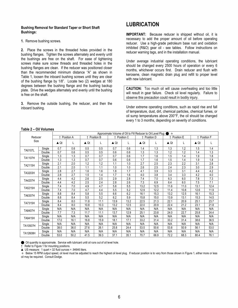
LUBRICATIONIMPORTANT: Because reducer is shipped without oil, it isnecessary to add the proper amount of oil before operatingreducer. Use a high-grade petroleum base rust and oxidationinhibited (R&O) gear oil - see tables. Follow instructions onreducer warning tags, and in the installation manual.
Under average industrial operating conditions, the lubricantshould be changed every 2500 hours of operation or every 6months, whichever occurs first. Drain reducer and flush withkerosene, clean magnetic drain plug and refill to proper levelwith new lubricant.
CAUTION: Too much oil will cause overheating and too littlewill result in gear failure. Check oil level regularly. Failure toobserve this precaution could result in bodily injury.
Under extreme operating conditions, such as rapid rise and fallof temperature, dust, dirt, chemical particles, chemical fumes, oroil sump temperatures above 200°F, the oil should be changedevery 1 to 3 months, depending on severity of conditions.
Table 2 – Oil VolumesApproximate Volume of Oil to Fill Reducer to Oil Level Plug � �
Reducer † Position A † Position B † Position C † Position D † Position E † Position FSize ▲Qt L ▲Qt L ▲Qt L ▲Qt L ▲Qt L ▲Qt L
Single 0.7 0.6 0.5 0.5 0.7 0.6 1.4 1.3 1.3 1.2 1.5 1.4TA0107L Double 0.7 0.6 0.5 0.5 0.6 0.6 1.3 1.3 1.2 1.2 1.4 1.3Single 1.3 1.3 0.7 0.7 0.7 0.6 1.7 1.6 1.5 1.4 1.9 1.8TA1107H Double 1.3 1.3 0.7 0.7 0.6 0.6 1.7 1.6 1.5 1.4 1.9 1.8Single 2.1 2.0 1.2 1.2 1.1 1.0 2.7 2.5 2.3 2.2 3.1 2.8TA2115H Double 2.1 2.0 1.1 1.1 1.0 1.0 2.6 2.5 2.4 2.3 3.0 2.9Single 2.8 2.7 1.6 1.6 1.8 1.7 4.1 3.9 3.3 3.1 4.4 4.2TA3203H Double 2.8 2.7 1.5 1.4 1.7 1.6 4.0 3.8 3.4 3.3 4.2 4.0Single 4.4 4.2 2.6 2.5 2.9 2.8 7.4 7.0 6.3 6.0 7.8 7.3TA4207H Double 4.4 4.2 2.5 2.4 2.8 2.6 7.3 6.9 6.4 6.0 7.5 7.1Single 7.4 7.0 4.9 4.7 5.8 5.5 13.2 12.5 11.6 11.0 13.1 12.4TA5215H Double 7.4 7.0 4.7 4.4 5.5 5.2 12.9 12.2 11.4 10.8 12.6 11.9Single 8.8 8.4 5.8 5.5 6.6 6.2 16.1 15.3 13.2 12.5 16.1 15.3TA6307H Double 8.8 8.4 5.5 5.2 6.2 5.9 15.8 15.0 13.9 13.1 15.3 14.5Single 8.4 8.0 11.8 11.1 13.9 13.2 22.5 21.3 22.1 20.9 25.1 23.7TA7315H Double 8.4 8.0 10.8 10.3 13.2 12.5 22.0 20.9 22.4 21.2 23.1 21.8Single N/A N/A N/A N/A N/A N/A N/A N/A N/A N/A N/A N/ATA8407H Double 7.7 7.3 11.7 11.1 13.7 12.9 25.1 23.8 24.0 22.7 25.8 24.4Single N/A N/A N/A N/A N/A N/A N/A N/A N/A N/A N/A N/ATA9415H Double 17.0 16.1 16.8 15.9 18.1 17.1 33.2 31.4 33.2 31.4 38.6 36.5Single N/A N/A N/A N/A N/A N/A N/A N/A N/A N/A N/A N/ATA10507H Double 38.0 36.0 27.6 26.1 25.8 24.4 53.5 50.6 53.8 50.9 56.1 53.0Single N/A N/A N/A N/A N/A N/A N/A N/A N/A N/A N/A N/ATA12608H Double 53.0 50.2 41.5 39.3 37.1 35.1 70.7 66.9 72.2 68.3 80.4 76.1
� Oil quantity is approximate. Service with lubricant until oil runs out of oil level hole.† Refer to Figure 1 for mounting positions.▲ US measure: 1 quart = 32 fluid ounces = .94646 liters.� Below 15 RPM output speed, oil level must be adjusted to reach the highest oil level plug. If reducer position is to vary from those shown in Figure 1, either more or lessoil may be required. Consult Dodge.

7
Table 3 – Oil RecommendationsISO Grades For Ambient Temperatures of 50˚F to 125˚F �
Torque-Arm II Reducer SizeOutputRPM TA0107L TA1107H TA2115H TA3203H TA4207H TA5215H TA6307H TA7315H TA8407H TA9415H TA10507H TA12608H
301 – 400 320 320 320 220 220 220 220 220 220 220 220 220201 – 300 320 320 320 220 220 220 220 220 220 220 220 220151 – 200 320 320 320 220 220 220 220 220 220 220 220 220126 – 150 320 320 320 220 220 220 220 220 220 220 220 220101 – 125 320 320 320 320 220 220 220 220 220 220 220 22081 – 100 320 320 320 320 320 220 220 220 220 220 220 22041 – 80 320 320 320 320 320 220 220 220 220 220 220 22011 – 40 320 320 320 320 320 320 320 320 320 320 220 2201 – 10 320 320 320 320 320 320 320 320 320 320 320 320
ISO Grades For Ambient Temperatures of 15˚F to 60˚F �Torque-Arm II Reducer SizeOutput
RPM TA0107L TA1107H TA2115H TA3203H TA4207H TA5215H TA6307H TA7315H TA8407H TA9415H TA10507H TA12608H301 – 400 220 220 220 150 150 150 150 150 150 150 150 150201 – 300 220 220 220 150 150 150 150 150 150 150 150 150151 – 200 220 220 220 150 150 150 150 150 150 150 150 150126 – 150 220 220 220 150 150 150 150 150 150 150 150 150101 – 125 220 220 220 220 150 150 150 150 150 150 150 15081 – 100 220 220 220 220 220 150 150 150 150 150 150 15041 – 80 220 220 220 220 220 150 150 150 150 150 150 15011 – 40 220 220 220 220 220 220 220 220 220 220 150 1501 – 10 220 220 220 220 220 220 220 220 220 220 220 220
� Notes:1. Assumes auxiliary cooling where recommended in the catalog.2. Pour point of lubricant selected should be at least 10°F lower than expected minimum ambient starting temperature.3. Extreme pressure (EP) lubricants are not necessary for average operating conditions. When properly selected for specific applications, TORQUE-ARM II backstops aresuitable for use with EP lubricants.4. Special lubricants may be required for food and drug industry applications where contact with the product being manufactured may occur. Consult a lubricationmanufacturer’s representative for his recommendations.5. For reducers operating in ambient temperatures between -22°F (-30°C) and 20°F (–6.6°C) use a synthetic hydrocarbon lubricant, 100 ISO grade or AGMA 3 grade (forexample, Mobil SHC627). Above 125°F (51°C), consult DODGE Gear Application Engineering (864) 288-9050 for lubrication recommendation.6. Mobil SHC630 Series oil is recommended for high ambient temperatures.

8
GUIDELINES FOR TORQUE-ARM IIREDUCER LONG-TERM STORAGEDuring periods of long storage, or when waiting for delivery orinstallation of other equipment, special care should be taken toprotect a gear reducer to have it ready to be in the bestcondition when placed into service.
By taking special precautions, problems such as seal leakageand reducer failure due to lack of lubrication, improperlubrication quantity, or contamination can be avoided. Thefollowing precautions will protect gear reducers during periods ofextended storage:
Preparation:
1. Drain oil from the unit. Add a vapor phase corrosioninhibiting oil (VCI-105 oil by Daubert Chemical Co.) inaccordance with Table 4.
2. Seal the unit airtight. Replace the vent plug with a standardpipe plug and wire the vent to the unit.
3. Cover all unpainted exterior parts with a waxy rustpreventative compound that will keep oxygen away from thebare metal. (Non-Rust X-110 by Daubert Chemical Co. orequivalent)
4. The instruction manuals and lubrication tags are paper andmust be kept dry. Either remove these documents and storethem inside, or cover the unit with a durable waterproof coverwhich can keep moisture away.
5. Protect reducer from dust, moisture, and other contaminantsby storing the unit in a dry area.
6. In damp environments, the reducer should be packed insidea moisture-proof container or an envelope of polyethylenecontaining a desiccant material. If the reducer is to be storedoutdoors, cover the entire exterior with a rust preventative.
When placing the reducer into service:
1. Fill the unit to the proper oil level using a recommendedlubricant. The VCI oil will not affect the new lubricant.
2. Clean the shaft extensions with petroleum solvents.
3. Assemble the vent plug into the proper hole.
Follow the installation instructions provided in this manual.
Table 4 – Quantities of VCI #105 OilReducer Size Quantity (Ounces / Milliliter)
TA0107L 1 / 30TA1107H 1 / 30TA2115H 1 / 30TA3203H 1 / 30TA4207H 1 / 30TA5215H 2 / 59TA6307H 2 / 59TA7315H 3 / 89TA8407H 3 / 89TA9415H 4 / 118TA10507H 6 / 177TA12608H 8 / 237
VCI #105 and #10 are interchangeable.VCI #105 is more readily available.
9
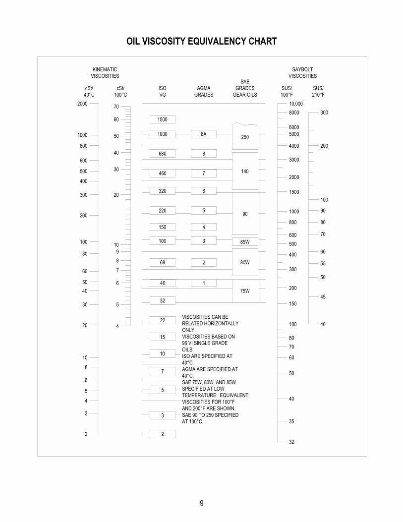
OIL VISCOSITY EQUIVALENCY CHART
2000
1000
800
600
500
400
300
200
100
80
60
5040
30
20
10
8
6
5
4
3
2
70
60
50
40
30
20
10
8
5
4
9
7
6
1500
1000
680
460
320
220
150
100
68
8A
8
7
6
5
4
3
2
85W
250
140
90
80W
46
32
22
15
10
7
5
175W
3
2
300
200
150
100
8070
60
50
40
35
32
400
500600
800
1000
1500
2000
3000
4000
50006000
800010,000
cSt/40°C 100°C
cSt/ ISOVG
AGMAGRADES
GRADESGEAR OILS
SUS/100°F
SUS/210°F
SAE
KINEMATICVISCOSITIES
SAYBOLTVISCOSITIES
200
300
100
90
80
70
60
55
50
45
40VISCOSITIES CAN BERELATED HORIZONTALLYONLY.VISCOSITIES BASED ON96 VI SINGLE GRADEOILS.ISO ARE SPECIFIED AT40°C.AGMA ARE SPECIFIED AT40°C.SAE 75W, 80W, AND 85WSPECIFIED AT LOWTEMPERATURE. EQUIVALENTVISCOSITIES FOR 100°FAND 200°F ARE SHOWN.SAE 90 TO 250 SPECIFIEDAT 100°C.
10
COOLING FAN INSTALLATIONWARNING: To ensure that drive is not unexpectedly started,turn off and lock out or tag power source before proceeding.Remove all external loads from drive before removing orservicing drive or accessories. Failure to observe theseprecautions could result in bodily injury.
Unpack all components and inspect for shipping damage. Donot use any component that has been damaged or modified.Make sure all components are clean and free of any foreignmaterial prior to assembly. Cooling fan assembly is designed tofit onto the input shaft before placement of sheeves or beltguard assembly.
Installation for TA4207CF and TA5215CF:
1. Referring to Figure 2, install tapered bushing (9) into bore offan blade assembly (2) and loosely install the three set screwsprovided with fan. Snug set screws but do not tighten at thistime.
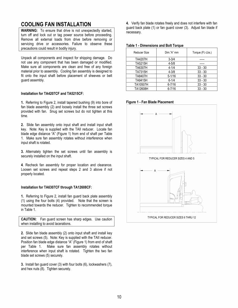
2. Slide fan assembly onto input shaft and install input shaftkey. Note: Key is supplied with the TAII reducer. Locate fanblade edge distance “A” (Figure 1) from end of shaft per Table1. Make sure fan assembly rotates without interference wheninput shaft is rotated.
3. Alternately tighten the set screws until fan assembly issecurely installed on the input shaft.
4. Recheck fan assembly for proper location and clearance.Loosen set screws and repeat steps 2 and 3 above if notproperly located.
Installation for TA6307CF through TA12608CF:
1. Referring to Figure 2, install fan guard back plate assembly(1) using the four bolts (4) provided. Note that the screen ismounted towards the reducer. Tighten to recommended torquein Table 1.
CAUTION: Fan guard screen has sharp edges. Use cautionwhen installing to avoid lacerations.
2. Slide fan blade assembly (2) onto input shaft and install keyand set screws (5). Note: Key is supplied with the TAII reducer.Position fan blade edge distance “A” (Figure 1) from end of shaftper Table 1. Make sure fan assembly rotates withoutinterference when input shaft is rotated. Tighten the two fanblade set screws (5) securely.
3. Install fan guard cover (3) with four bolts (6), lockwashers (7),and hex nuts (8). Tighten securely.
4. Verify fan blade rotates freely and does not interfere with fanguard back plate (1) or fan guard cover (3). Adjust fan blade ifnecessary.
Table 1 - Dimensions and Bolt TorqueReducer Size Dim.”A” mm Torque (Ft.-Lbs.)
TA4207H 3-3/4 -----TA5215H 4-5/8 -----TA6307H 4-1/4 33 - 30TA7315H 4-3/8 33 - 30TA8407H 5-1/16 33 - 30TA9415H 6-1/4 33 - 30TA10507H 6-7/16 33 - 30TA12608H 6-7/16 33 - 30
Figure 1 - Fan Blade Placement
A
A
TYPICAL FOR REDUCER SIZES 4 AND 5
TYPICAL FOR REDUCER SIZES 6 THRU 12

11
Figure 2 – Parts Identification
TYPICAL COOLING FAN ASSEMBLYFOR REDUCER SIZES 6 THROUGH 12
TYPICAL COOLING FAN ASSEMBLY FOR REDUCER SIZES 4 AND 5
8
7
1
42
3
5
69
2
Table 2 – Cooling Fan Part NumbersDescription Ref.
Number Quantity TA4207 TA5215 TA6307 TA7315 TA8407 TA9415 TA10507 TA12608
Cooling Fan Assembly � ----- 1 904106 905106 906106 907106 907106 909106 910106 912106Fan Guard Plate Assy.� 1 1 ----- ----- 906519 906519 906519 909519 909519 912519Fan Blade� 2 1 904517 905517 906517 907517 907517 909517 910517 910517Fan Guard Cover� 3 1 ----- ----- 906521 906521 906521 909521 909521 909521Mounting Bolt� 4 4 ----- ----- 411294 411294 411294 411294 411294 411294Fan Set Screw� 5 2 ----- ----- 400086 400086 400086 400086 400086 400086Cover Bolt� 6 4 ----- ----- 411390 411390 411390 411390 411390 411390Lockwasher� 7 4 ----- ----- 419010 419010 419010 419010 419010 419010Hex Nut� 8 4 ----- ----- 407085 407085 407085 407085 407085 407085Taper Bushing Assy.�� 9 1 117162 117092 ----- ----- ----- ----- ----- -----
� Assembly includes parts listed below marked �� Set screws are included with taper bushing assembly.
12
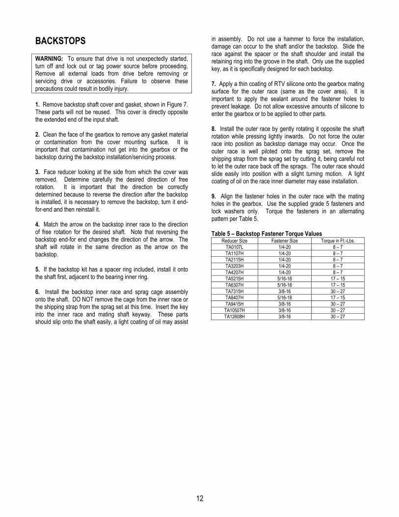
BACKSTOPSWARNING: To ensure that drive is not unexpectedly started,turn off and lock out or tag power source before proceeding.Remove all external loads from drive before removing orservicing drive or accessories. Failure to observe theseprecautions could result in bodily injury.
1. Remove backstop shaft cover and gasket, shown in Figure 7.These parts will not be reused. This cover is directly oppositethe extended end of the input shaft.
2. Clean the face of the gearbox to remove any gasket materialor contamination from the cover mounting surface. It isimportant that contamination not get into the gearbox or thebackstop during the backstop installation/servicing process.
3. Face reducer looking at the side from which the cover wasremoved. Determine carefully the desired direction of freerotation. It is important that the direction be correctlydetermined because to reverse the direction after the backstopis installed, it is necessary to remove the backstop, turn it end-for-end and then reinstall it.
4. Match the arrow on the backstop inner race to the directionof free rotation for the desired shaft. Note that reversing thebackstop end-for end changes the direction of the arrow. Theshaft will rotate in the same direction as the arrow on thebackstop.
5. If the backstop kit has a spacer ring included, install it ontothe shaft first, adjacent to the bearing inner ring.
6. Install the backstop inner race and sprag cage assemblyonto the shaft. DO NOT remove the cage from the inner race orthe shipping strap from the sprag set at this time. Insert the keyinto the inner race and mating shaft keyway. These partsshould slip onto the shaft easily, a light coating of oil may assist
in assembly. Do not use a hammer to force the installation,damage can occur to the shaft and/or the backstop. Slide therace against the spacer or the shaft shoulder and install theretaining ring into the groove in the shaft. Only use the suppliedkey, as it is specifically designed for each backstop.
7. Apply a thin coating of RTV silicone onto the gearbox matingsurface for the outer race (same as the cover area). It isimportant to apply the sealant around the fastener holes toprevent leakage. Do not allow excessive amounts of silicone toenter the gearbox or to be applied to other parts.
8. Install the outer race by gently rotating it opposite the shaftrotation while pressing lightly inwards. Do not force the outerrace into position as backstop damage may occur. Once theouter race is well piloted onto the sprag set, remove theshipping strap from the sprag set by cutting it, being careful notto let the outer race back off the sprags. The outer race shouldslide easily into position with a slight turning motion. A lightcoating of oil on the race inner diameter may ease installation.
9. Align the fastener holes in the outer race with the matingholes in the gearbox. Use the supplied grade 5 fasteners andlock washers only. Torque the fasteners in an alternatingpattern per Table 5.
Table 5 – Backstop Fastener Torque ValuesReducer Size Fastener Size Torque in Ft.-Lbs.
TA0107L 1/4-20 8 – 7TA1107H 1/4-20 8 – 7TA2115H 1/4-20 8 – 7TA3203H 1/4-20 8 – 7TA4207H 1/4-20 8 – 7TA5215H 5/16-18 17 – 15TA6307H 5/16-18 17 – 15TA7315H 3/8-16 30 – 27TA8407H 5/16-18 17 – 15TA9415H 3/8-16 30 – 27TA10507H 3/8-16 30 – 27TA12608H 3/8-16 30 – 27
13
ARROW ON HUB OF INSTALLEDBACKSTOP MUST MATCHDIRECTION OF DESIRED
SHAFT ROTATION
BACKSTOP SHAFTCOVER GASKET
BACKSTOPSHAFT COVER
SPACER (IF APPLICABLE)
OUTER RACE
INNER RACE
RETAININGRING
BACKSTOPFASTENERS
BACKSTOPKEY
REDUCER WITHBACKSTOP INSTALLED
REDUCER WITHOUTBACKSTOP INSTALLED
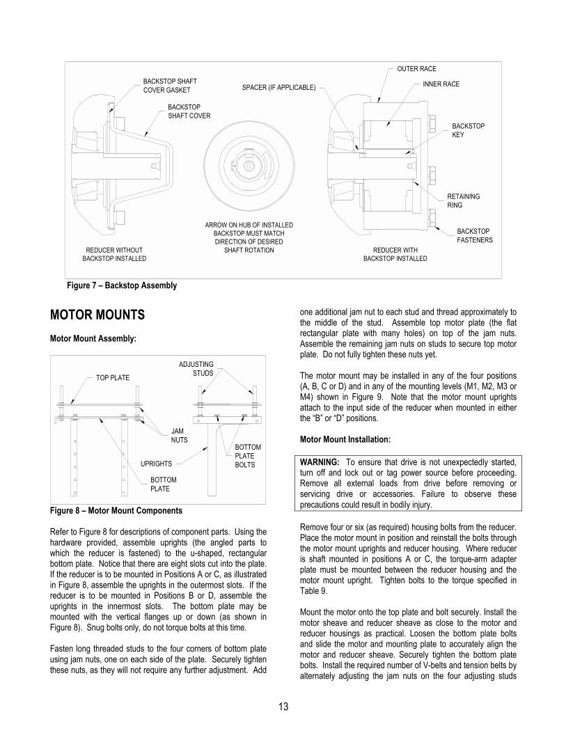
Figure 7 – Backstop Assembly
MOTOR MOUNTSMotor Mount Assembly:
BOTTOMPLATE
TOP PLATE
ADJUSTINGSTUDS
UPRIGHTS
JAMNUTS
BOTTOMPLATEBOLTS
Figure 8 – Motor Mount Components
Refer to Figure 8 for descriptions of component parts. Using thehardware provided, assemble uprights (the angled parts towhich the reducer is fastened) to the u-shaped, rectangularbottom plate. Notice that there are eight slots cut into the plate.If the reducer is to be mounted in Positions A or C, as illustratedin Figure 8, assemble the uprights in the outermost slots. If thereducer is to be mounted in Positions B or D, assemble theuprights in the innermost slots. The bottom plate may bemounted with the vertical flanges up or down (as shown inFigure 8). Snug bolts only, do not torque bolts at this time.
Fasten long threaded studs to the four corners of bottom plateusing jam nuts, one on each side of the plate. Securely tightenthese nuts, as they will not require any further adjustment. Add
one additional jam nut to each stud and thread approximately tothe middle of the stud. Assemble top motor plate (the flatrectangular plate with many holes) on top of the jam nuts.Assemble the remaining jam nuts on studs to secure top motorplate. Do not fully tighten these nuts yet.
The motor mount may be installed in any of the four positions(A, B, C or D) and in any of the mounting levels (M1, M2, M3 orM4) shown in Figure 9. Note that the motor mount uprightsattach to the input side of the reducer when mounted in eitherthe “B” or “D” positions.
Motor Mount Installation:
WARNING: To ensure that drive is not unexpectedly started,turn off and lock out or tag power source before proceeding.Remove all external loads from drive before removing orservicing drive or accessories. Failure to observe theseprecautions could result in bodily injury.
Remove four or six (as required) housing bolts from the reducer.Place the motor mount in position and reinstall the bolts throughthe motor mount uprights and reducer housing. Where reduceris shaft mounted in positions A or C, the torque-arm adapterplate must be mounted between the reducer housing and themotor mount upright. Tighten bolts to the torque specified inTable 9.
Mount the motor onto the top plate and bolt securely. Install themotor sheave and reducer sheave as close to the motor andreducer housings as practical. Loosen the bottom plate boltsand slide the motor and mounting plate to accurately align themotor and reducer sheave. Securely tighten the bottom platebolts. Install the required number of V-belts and tension belts byalternately adjusting the jam nuts on the four adjusting studs
14
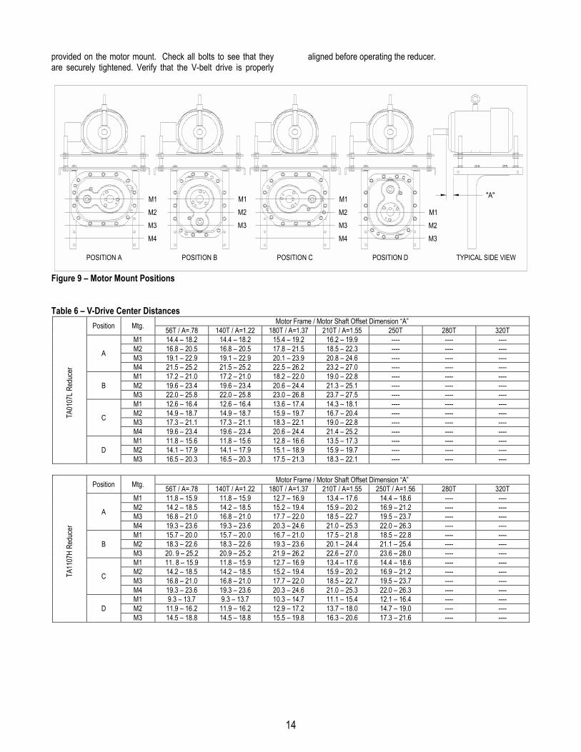
provided on the motor mount. Check all bolts to see that theyare securely tightened. Verify that the V-belt drive is properly
aligned before operating the reducer.
POSITION A POSITION B POSITION C POSITION D
M1M2M3
M4
M3M2M1
M4
M3M2M1
M3M2M1
TYPICAL SIDE VIEW
"A"
Figure 9 – Motor Mount Positions
Table 6 – V-Drive Center DistancesMotor Frame / Motor Shaft Offset Dimension “A”Position Mtg. 56T / A=.78 140T / A=1.22 180T / A=1.37 210T / A=1.55 250T 280T 320T
M1 14.4 – 18.2 14.4 – 18.2 15.4 – 19.2 16.2 – 19.9 ---- ---- ----M2 16.8 – 20.5 16.8 – 20.5 17.8 – 21.5 18.5 – 22.3 ---- ---- ----M3 19.1 – 22.9 19.1 – 22.9 20.1 – 23.9 20.8 – 24.6 ---- ---- ----A
M4 21.5 – 25.2 21.5 – 25.2 22.5 – 26.2 23.2 – 27.0 ---- ---- ----M1 17.2 – 21.0 17.2 – 21.0 18.2 – 22.0 19.0 – 22.8 ---- ---- ----M2 19.6 – 23.4 19.6 – 23.4 20.6 – 24.4 21.3 – 25.1 ---- ---- ----BM3 22.0 – 25.8 22.0 – 25.8 23.0 – 26.8 23.7 – 27.5 ---- ---- ----M1 12.6 – 16.4 12.6 – 16.4 13.6 – 17.4 14.3 – 18.1 ---- ---- ----M2 14.9 – 18.7 14.9 – 18.7 15.9 – 19.7 16.7 – 20.4 ---- ---- ----M3 17.3 – 21.1 17.3 – 21.1 18.3 – 22.1 19.0 – 22.8 ---- ---- ----C
M4 19.6 – 23.4 19.6 – 23.4 20.6 – 24.4 21.4 – 25.2 ---- ---- ----M1 11.8 – 15.6 11.8 – 15.6 12.8 – 16.6 13.5 – 17.3 ---- ---- ----M2 14.1 – 17.9 14.1 – 17.9 15.1 – 18.9 15.9 – 19.7 ---- ---- ----
TA01
07L R
educ
er
DM3 16.5 – 20.3 16.5 – 20.3 17.5 – 21.3 18.3 – 22.1 ---- ---- ----
Motor Frame / Motor Shaft Offset Dimension “A”Position Mtg. 56T / A=.78 140T / A=1.22 180T / A=1.37 210T / A=1.55 250T / A=1.56 280T 320TM1 11.8 – 15.9 11.8 – 15.9 12.7 – 16.9 13.4 – 17.6 14.4 – 18.6 ---- ----M2 14.2 – 18.5 14.2 – 18.5 15.2 – 19.4 15.9 – 20.2 16.9 – 21.2 ---- ----M3 16.8 – 21.0 16.8 – 21.0 17.7 – 22.0 18.5 – 22.7 19.5 – 23.7 ---- ----A
M4 19.3 – 23.6 19.3 – 23.6 20.3 – 24.6 21.0 – 25.3 22.0 – 26.3 ---- ----M1 15.7 – 20.0 15.7 – 20.0 16.7 – 21.0 17.5 – 21.8 18.5 – 22.8 ---- ----M2 18.3 – 22.6 18.3 – 22.6 19.3 – 23.6 20.1 – 24.4 21.1 – 25.4 ---- ----BM3 20. 9 – 25.2 20.9 – 25.2 21.9 – 26.2 22.6 – 27.0 23.6 – 28.0 ---- ----M1 11. 8 – 15.9 11.8 – 15.9 12.7 – 16.9 13.4 – 17.6 14.4 – 18.6 ---- ----M2 14.2 – 18.5 14.2 – 18.5 15.2 – 19.4 15.9 – 20.2 16.9 – 21.2 ---- ----M3 16.8 – 21.0 16.8 – 21.0 17.7 – 22.0 18.5 – 22.7 19.5 – 23.7 ---- ----C
M4 19.3 – 23.6 19.3 – 23.6 20.3 – 24.6 21.0 – 25.3 22.0 – 26.3 ---- ----M1 9.3 – 13.7 9.3 – 13.7 10.3 – 14.7 11.1 – 15.4 12.1 – 16.4 ---- ----M2 11.9 – 16.2 11.9 – 16.2 12.9 – 17.2 13.7 – 18.0 14.7 – 19.0 ---- ----
TA11
07H
Redu
cer
DM3 14.5 – 18.8 14.5 – 18.8 15.5 – 19.8 16.3 – 20.6 17.3 – 21.6 ---- ----

15
Motor Frame / Motor Shaft Offset Dimension “A”Position Mtg. 56T / A=.78 140T / A=1.22 180T / A=1.37 210T / A=1.55 250T / A=1.56 280T 320TM1 13.6 – 17.2 13.6 – 17.2 14.6 – 18.1 15.3 – 18.9 16.3 – 19.8 ---- ----M2 16.6 – 20.1 16.6 – 20.1 17.5 – 21.1 18.3 – 21.9 19.2 – 22.8 ---- ----M3 19.5 – 23.1 19.5 – 23.1 20.5 – 24.1 21.2 – 24.9 22.2 – 25.9 ---- ----A
M4 22.5 – 26.2 22.5 – 26.2 23.5 – 27.1 24.2 – 27.9 25.2 – 28.9 ---- ----M1 18.5 – 22.2 18.5 – 22.2 19.5 – 23.2 20.3 – 24.0 21.3 – 25.0 ---- ----M2 21.6 – 25.3 21.6 – 25.3 22.6 – 26.3 23.3 – 27.0 24.3 – 28.0 ---- ----BM3 24.6 – 28.3 24.6 – 28.3 25.6 – 29.3 26.4 – 30.1 27.4 – 31.1 ---- ----M1 13.6 – 17.2 13.6 – 17.2 14.6 – 18.1 15.3 – 18.9 16.3 – 19.8 ---- ----M2 16.6 – 20.1 16.6 – 20.1 17.5 – 21.1 18.3 – 21.9 19.2 – 22.8 ---- ----M3 19.5 – 23.1 19.5 – 23.1 20.5 – 24.1 21.2 – 24.9 22.2 – 25.9 ---- ----C
M4 22.5 – 26.2 22.5 – 26.2 23.5 – 27.1 24.2 – 27.9 25.2 – 28.9 ---- ----M1 10.4 – 14.1 10.4 – 14.1 11.4 – 15.1 12.2 – 15.9 13.2 – 16.9 ---- ----M2 13.5 – 17.2 13.5 – 17.2 14.5 – 18.2 15.3 – 19.0 16.3 – 20.0 ---- ----
TA21
15H
Redu
cer
DM3 16.6 – 20.3 16.6 – 20.3 17.6 – 21.3 18.3 – 22.0 22.0 – 23.0 ---- ----
Motor Frame / Motor Shaft Offset Dimension “A”Position Mtg. 140T / A=1.22 180T / A=1.37 210T / A=1.55 250T / A=1.56 280T / A=1.16 320T 360TM1 14.6 – 18.4 15.5 – 19.4 16.2 – 20.1 17.2 – 21.1 17.9 – 21.8 ---- ----M2 17.9 – 21.8 18.9 – 22.8 19.6 – 23.5 20.5 – 24.5 21.3 – 25.2 ---- ----M3 21.2 – 25.2 22.2 – 26.2 22.9 – 26.9 23.9 – 27.9 24.7 – 28.6 ---- ----A
M4 24.6 – 28.6 25.6 – 29.6 26.3 – 30.3 27.3 – 31.3 28.1 – 32.1 ---- ----M1 19.8 – 23.9 20.8 – 24.9 21.6 – 25.6 22.6 – 26.6 23.3 – 27.4 ---- ----M2 23.3 – 27.3 24.3 – 28.3 25.0 – 29.1 26.0 – 30.1 26.8 – 30.8 ---- ----BM3 26.7 – 30.8 27.7 – 31.8 28.5 – 32.5 29.5 – 33.5 30.2 – 34.3 ---- ----M1 13.6 – 17.4 14.5 – 18.4 15.2 – 19.1 16.2 – 20.1 16.9 – 20.8 ---- ----M2 16.9 – 20.8 17.8 – 21.7 18.6 – 22.5 19.5 – 23.5 20.2 – 24.2 ---- ----M3 20.2 – 24.2 21.2 – 25.1 21.9 – 25.9 22.9 – 26.9 23.6 – 27.6 ---- ----C
M4 23.6 – 27.6 24.6 – 28.5 25.3 – 29.3 26.3 – 30.3 27.0 – 31.0 ---- ----M1 10.2 – 14.2 11.2 – 15.2 11.9 – 16.0 12.9 – 17.0 13.7 – 17.7 ---- ----M2 13.6 – 17.7 14.6 – 18.7 15.4 – 19.4 16.4 – 20.4 17.1 – 21.2 ---- ----
TA32
03H
Redu
cer
DM3 17.1 – 21.1 18.1 – 22.1 18.8 – 22.9 19.8 – 23.9 20.6 – 24.6 ---- ----
Motor Frame / Motor Shaft Offset Dimension “A”Position Mtg. 140T / A=1.22 180T / A=1.37 210T / A=1.55 250T / A=1.56 280T / A=1.16 320T / A=.38 360TM1 17.3 – 21.1 18.3 – 22.1 19.0 – 22.8 19.9 – 23.8 20.6 – 24.5 21.6 – 25.5 ----M2 21.2 – 25.1 22.2 – 26.1 22.9 – 26.8 23.9 – 27.8 24.6 – 28.6 25.6 – 29.5 ----M3 25.2 – 29.2 26.2 – 30.2 26.9 – 30.9 27.9 – 31.9 28.7 – 32.6 29.6 – 33.6 ----A
M4 29.3 – 33.2 30.2 – 34.2 31.0 – 34.9 32.0 – 35.9 32.7 – 36.7 33.7 – 37.7 ----M1 22.6 – 26.7 23.6 – 27.7 24.4 – 28.4 25.4 – 29.4 26.1 – 30.2 27.1 – 31.2 ----M2 26.8 – 30.8 27.8 – 31.8 28.5 – 32.5 29.5 – 33.5 30.3 – 34.3 31.3 – 35.3 ----BM3 30.9 – 34.9 31.9 – 35.9 32.6 – 36.7 33.6 – 37.7 34.4 – 38.4 35.4 – 39.4 ----M1 15.4 – 19.2 16.3 – 20.1 17.0 – 20.8 18.0 – 21.8 18.7 – 22.5 19.6 – 23.5 ----M2 19.3 – 23.1 20.2 – 24.1 20.9 – 24.8 21.9 – 25.8 22.6 – 26.5 23.6 – 27.5 ----M3 23.2 – 27.2 24.2 – 28.1 24.9 – 28.9 25.9 – 29.9 26.6 – 30.6 27.6 – 31.6 ----C
M4 27.3 – 31.2 28.2 – 32.2 29.0 – 32.9 29.9 – 33.9 30.7 – 34.6 31.7 – 35.6 ----M1 12.2 – 16.2 13.2 – 17.2 14.0 – 18.0 15.0 – 19.0 15.7 – 19.7 16.7 – 20.7 ----M2 16.3 – 20.4 17.3 – 21.4 18.1 – 22.1 19.1 – 23.1 19.8 – 23.9 20.8 – 24.9 ----
TA42
07H
Redu
cer
DM3 20.4 – 24.5 21.4 – 25.5 22.2 – 26.2 23.2 – 27.2 23.9 – 28.0 24.9 – 29.0 ----
Motor Frame / Motor Shaft Offset Dimension “A”Position Mtg. 180T / A=1.37 210T / A=1.55 250T / A=1.56 280T / A=1.16 320T / A=.38 360T / A=1.01 400TM1 19.5 – 23.4 20.2 – 24.1 21.1 – 25.1 21.8 – 25.8 22.8 – 26.8 23.8 – 27.8 ----M2 24.2 – 28.3 25.0 – 29.0 25.9 – 30.0 26.7 – 30.7 27.6 – 31.7 28.6 – 32.7 ----M3 29.1 – 33.2 29.8 – 33.9 30.8 – 34.9 31.5 – 35.6 32.5 – 36.6 33.5 – 37.6 ----A
M4 34.0 – 38.1 34.7 – 38.8 35.7 – 39.8 36.5 – 40.6 37.4 – 41.5 38.4 – 42.5 ----M1 26.2 – 30.3 26.9 – 31.1 27.9 – 32.1 28.7 – 32.8 29.7 – 33.8 30.7 – 34.8 ----M2 31.2 – 35.3 31.9 – 36.1 32.9 – 37.1 33.7 – 37.8 34.7 – 38.8 35.7 – 39.8 ----BM3 36.2 – 40.3 36.9 – 41.1 37.9 – 42.1 38.7 – 42.8 39.7 – 43.8 40.7 – 44.8 ----M1 16.4 – 20.3 17.1 – 21.0 18.0 – 21.9 18.7 – 22.6 19.7 – 23.6 20.6 – 24.6 ----M2 21.1 – 25.1 21.8 – 25.8 22.8 – 26.8 23.5 – 27.5 24.4 – 28.5 25.4 – 29.4 ----M3 25.9 – 29.9 26.6 – 30.7 27.6 – 31.6 28.3 – 32.4 29.3 – 33.4 30.3 – 34.3 ----C
M4 30.8 – 34.8 31.5 – 35.6 32.5 – 36.6 32.2 – 37.3 34.2 – 38.3 35.2 – 39.3 ----M1 17.7 – 21.8 18.4 – 22.6 19.4 – 23.6 20.2 – 24.3 21.2 – 25.3 22.2 – 26.3 ----M2 22.7 – 26.8 23.4 – 27.6 24.4 – 28.6 25.2 – 29.3 26.2 – 30.3 27.2 – 31.3 ----
TA52
15H
Redu
cer
DM3 N/A N/A N/A N/A N/A N/A ----
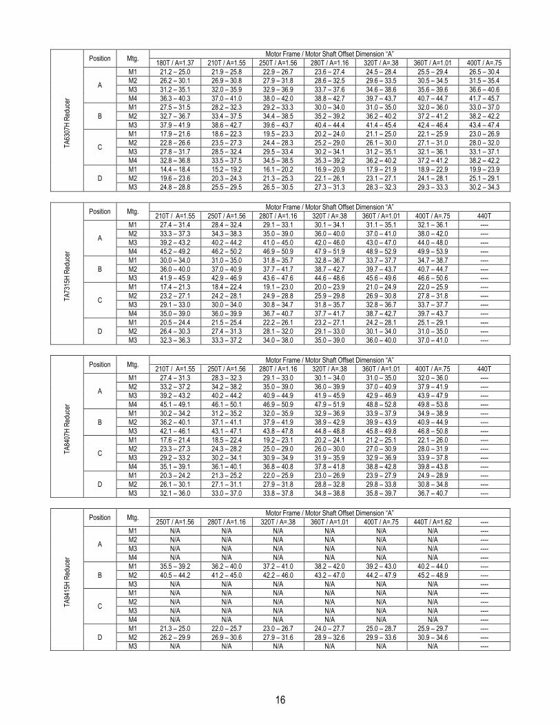
16
Motor Frame / Motor Shaft Offset Dimension “A”Position Mtg. 180T / A=1.37 210T / A=1.55 250T / A=1.56 280T / A=1.16 320T / A=.38 360T / A=1.01 400T / A=.75M1 21.2 – 25.0 21.9 – 25.8 22.9 – 26.7 23.6 – 27.4 24.5 – 28.4 25.5 – 29.4 26.5 – 30.4M2 26.2 – 30.1 26.9 – 30.8 27.9 – 31.8 28.6 – 32.5 29.6 – 33.5 30.5 – 34.5 31.5 – 35.4M3 31.2 – 35.1 32.0 – 35.9 32.9 – 36.9 33.7 – 37.6 34.6 – 38.6 35.6 – 39.6 36.6 – 40.6A
M4 36.3 – 40.3 37.0 – 41.0 38.0 – 42.0 38.8 – 42.7 39.7 – 43.7 40.7 – 44.7 41.7 – 45.7M1 27.5 – 31.5 28.2 – 32.3 29.2 – 33.3 30.0 – 34.0 31.0 – 35.0 32.0 – 36.0 33.0 – 37.0M2 32.7 – 36.7 33.4 – 37.5 34.4 – 38.5 35.2 – 39.2 36.2 – 40.2 37.2 – 41.2 38.2 – 42.2BM3 37.9 – 41.9 38.6 – 42.7 39.6 – 43.7 40.4 – 44.4 41.4 – 45.4 42.4 – 46.4 43.4 – 47.4M1 17.9 – 21.6 18.6 – 22.3 19.5 – 23.3 20.2 – 24.0 21.1 – 25.0 22.1 – 25.9 23.0 – 26.9M2 22.8 – 26.6 23.5 – 27.3 24.4 – 28.3 25.2 – 29.0 26.1 – 30.0 27.1 – 31.0 28.0 – 32.0M3 27.8 – 31.7 28.5 – 32.4 29.5 – 33.4 30.2 – 34.1 31.2 – 35.1 32.1 – 36.1 33.1 – 37.1C
M4 32.8 – 36.8 33.5 – 37.5 34.5 – 38.5 35.3 – 39.2 36.2 – 40.2 37.2 – 41.2 38.2 – 42.2M1 14.4 – 18.4 15.2 – 19.2 16.1 – 20.2 16.9 – 20.9 17.9 – 21.9 18.9 – 22.9 19.9 – 23.9M2 19.6 – 23.6 20.3 – 24.3 21.3 – 25.3 22.1 – 26.1 23.1 – 27.1 24.1 – 28.1 25.1 – 29.1
TA63
07H
Redu
cer
DM3 24.8 – 28.8 25.5 – 29.5 26.5 – 30.5 27.3 – 31.3 28.3 – 32.3 29.3 – 33.3 30.2 – 34.3
Motor Frame / Motor Shaft Offset Dimension “A”Position Mtg. 210T / A=1.55 250T / A=1.56 280T / A=1.16 320T / A=.38 360T / A=1.01 400T / A=.75 440TM1 27.4 – 31.4 28.4 – 32.4 29.1 – 33.1 30.1 – 34.1 31.1 – 35.1 32.1 – 36.1 ----M2 33.3 – 37.3 34.3 – 38.3 35.0 – 39.0 36.0 – 40.0 37.0 – 41.0 38.0 – 42.0 ----M3 39.2 – 43.2 40.2 – 44.2 41.0 – 45.0 42.0 – 46.0 43.0 – 47.0 44.0 – 48.0 ----A
M4 45.2 – 49.2 46.2 – 50.2 46.9 – 50.9 47.9 – 51.9 48.9 – 52.9 49.9 – 53.9 ----M1 30.0 – 34.0 31.0 – 35.0 31.8 – 35.7 32.8 – 36.7 33.7 – 37.7 34.7 – 38.7 ----M2 36.0 – 40.0 37.0 – 40.9 37.7 – 41.7 38.7 – 42.7 39.7 – 43.7 40.7 – 44.7 ----BM3 41.9 – 45.9 42.9 – 46.9 43.6 – 47.6 44.6 – 48.6 45.6 – 49.6 46.6 – 50.6 ----M1 17.4 – 21.3 18.4 – 22.4 19.1 – 23.0 20.0 – 23.9 21.0 – 24.9 22.0 – 25.9 ----M2 23.2 – 27.1 24.2 – 28.1 24.9 – 28.8 25.9 – 29.8 26.9 – 30.8 27.8 – 31.8 ----M3 29.1 – 33.0 30.0 – 34.0 30.8 – 34.7 31.8 – 35.7 32.8 – 36.7 33.7 – 37.7 ----C
M4 35.0 – 39.0 36.0 – 39.9 36.7 – 40.7 37.7 – 41.7 38.7 – 42.7 39.7 – 43.7 ----M1 20.5 – 24.4 21.5 – 25.4 22.2 – 26.1 23.2 – 27.1 24.2 – 28.1 25.1 – 29.1 ----M2 26.4 – 30.3 27.4 – 31.3 28.1 – 32.0 29.1 – 33.0 30.1 – 34.0 31.0 – 35.0 ----
TA73
15H
Redu
cer
DM3 32.3 – 36.3 33.3 – 37.2 34.0 – 38.0 35.0 – 39.0 36.0 – 40.0 37.0 – 41.0 ----
Motor Frame / Motor Shaft Offset Dimension “A”Position Mtg. 210T / A=1.55 250T / A=1.56 280T / A=1.16 320T / A=.38 360T / A=1.01 400T / A=.75 440TM1 27.4 – 31.3 28.3 – 32.3 29.1 – 33.0 30.1 – 34.0 31.0 – 35.0 32.0 – 36.0 ----M2 33.2 – 37.2 34.2 – 38.2 35.0 – 39.0 36.0 – 39.9 37.0 – 40.9 37.9 – 41.9 ----M3 39.2 – 43.2 40.2 – 44.2 40.9 – 44.9 41.9 – 45.9 42.9 – 46.9 43.9 – 47.9 ----A
M4 45.1 – 49.1 46.1 – 50.1 46.9 – 50.9 47.9 – 51.9 48.8 – 52.8 49.8 – 53.8 ----M1 30.2 – 34.2 31.2 – 35.2 32.0 – 35.9 32.9 – 36.9 33.9 – 37.9 34.9 – 38.9 ----M2 36.2 – 40.1 37.1 – 41.1 37.9 – 41.9 38.9 – 42.9 39.9 – 43.9 40.9 – 44.9 ----BM3 42.1 – 46.1 43.1 – 47.1 43.8 – 47.8 44.8 – 48.8 45.8 – 49.8 46.8 – 50.8 ----M1 17.6 – 21.4 18.5 – 22.4 19.2 – 23.1 20.2 – 24.1 21.2 – 25.1 22.1 – 26.0 ----M2 23.3 – 27.3 24.3 – 28.2 25.0 – 29.0 26.0 – 30.0 27.0 – 30.9 28.0 – 31.9 ----M3 29.2 – 33.2 30.2 – 34.1 30.9 – 34.9 31.9 – 35.9 32.9 – 36.9 33.9 – 37.8 ----C
M4 35.1 – 39.1 36.1 – 40.1 36.8 – 40.8 37.8 – 41.8 38.8 – 42.8 39.8 – 43.8 ----M1 20.3 – 24.2 21.3 – 25.2 22.0 – 25.9 23.0 – 26.9 23.9 – 27.9 24.9 – 28.9 ----M2 26.1 – 30.1 27.1 – 31.1 27.9 – 31.8 28.8 – 32.8 29.8 – 33.8 30.8 – 34.8 ----
TA84
07H
Redu
cer
DM3 32.1 – 36.0 33.0 – 37.0 33.8 – 37.8 34.8 – 38.8 35.8 – 39.7 36.7 – 40.7 ----
Motor Frame / Motor Shaft Offset Dimension “A”Position Mtg. 250T / A=1.56 280T / A=1.16 320T / A=.38 360T / A=1.01 400T / A=.75 440T / A=1.62 ----M1 N/A N/A N/A N/A N/A N/A ----M2 N/A N/A N/A N/A N/A N/A ----M3 N/A N/A N/A N/A N/A N/A ----A
M4 N/A N/A N/A N/A N/A N/A ----M1 35.5 – 39.2 36.2 – 40.0 37.2 – 41.0 38.2 – 42.0 39.2 – 43.0 40.2 – 44.0 ----M2 40.5 – 44.2 41.2 – 45.0 42.2 – 46.0 43.2 – 47.0 44.2 – 47.9 45.2 – 48.9 ----BM3 N/A N/A N/A N/A N/A N/A ----M1 N/A N/A N/A N/A N/A N/A ----M2 N/A N/A N/A N/A N/A N/A ----M3 N/A N/A N/A N/A N/A N/A ----C
M4 N/A N/A N/A N/A N/A N/A ----M1 21.3 – 25.0 22.0 – 25.7 23.0 – 26.7 24.0 – 27.7 25.0 – 28.7 25.9 – 29.7 ----M2 26.2 – 29.9 26.9 – 30.6 27.9 – 31.6 28.9 – 32.6 29.9 – 33.6 30.9 – 34.6 ----
TA94
15H
Redu
cer
DM3 N/A N/A N/A N/A N/A N/A ----

17
Motor Frame / Motor Shaft Offset Dimension “A”Position Mtg. 250T / A=1.56 280T / A=1.16 320T / A=.38 360T / A=1.01 400T / A=.75 440T / A=1.62 ----M1 N/A N/A N/A N/A N/A N/A ----M2 N/A N/A N/A N/A N/A N/A ----M3 N/A N/A N/A N/A N/A N/A ----A
M4 N/A N/A N/A N/A N/A N/A ----M1 46.7 – 50.5 47.5 – 51.2 48.5 – 52.2 49.5 – 53.2 50.5 – 54.2 51.5 – 55.2 ----M2 52.1 – 55.9 52.8 – 56.6 53.8 – 57.6 54.8 – 58.6 55.8 – 59.6 56.8 – 60.6 ----BM3 N/A N/A N/A N/A N/A N/A ----M1 N/A N/A N/A N/A N/A N/A ----M2 N/A N/A N/A N/A N/A N/A ----M3 N/A N/A N/A N/A N/A N/A ----C
M4 N/A N/A N/A N/A N/A N/A ----M1 17.7 – 21.4 18.4 – 22.2 19.4 – 23.2 20.4 – 24.2 21.4 – 25.2 22.4 – 26.2 ----M2 23.0 – 26.8 23.8 – 27.5 24.8 – 28.5 25.8 –29.5 26.8 – 30.5 27.8 – 31.5 ----
TA10
507H
Red
ucer
DM3 N/A N/A N/A N/A N/A N/A ----
Motor Frame / Motor Shaft Offset Dimension “A”Position Mtg. 250T / A=1.56 280T / A=1.16 320T / A=.38 360T / A=1.01 400T / A=.75 440T / A=1.62 ----M1 N/A N/A N/A N/A N/A N/A ----M2 N/A N/A N/A N/A N/A N/A ----M3 N/A N/A N/A N/A N/A N/A ----A
M4 N/A N/A N/A N/A N/A N/A ----M1 48.9 – 52.7 49.7 – 53.5 50.7 – 54.5 51.7 – 55.5 52.7 – 56.5 53.7 – 57.5 ----M2 54.5 – 58.3 55.3 – 59.1 56.3 – 60.1 57.3 – 61.1 58.3 – 62.1 59.3 – 63.1 ----BM3 N/A N/A N/A N/A N/A N/A ----M1 N/A N/A N/A N/A N/A N/A ----M2 N/A N/A N/A N/A N/A N/A ----M3 N/A N/A N/A N/A N/A N/A ----C
M4 N/A N/A N/A N/A N/A N/A ----M1 22.0 – 25.8 22.8 – 26.6 23.8 – 27.6 24.8 – 28.6 25.8 – 29.6 26.8 – 30.6 ----M2 N/A N/A N/A N/A N/A N/A ----
TA12
608H
Red
ucer
DM3 N/A N/A N/A N/A N/A N/A ----
TORQUE-ARM II BELT GUARDINSTALLATIONTwo different belt guards are available for the Torque-Arm IIspeed reducer. One belt guard assembly is designed formounting in position “B” and the other belt guard assembly isdesigned for mounting in position “C” as shown in Figure 10. Itis important that the mounting position of the Torque-Arm IIMotor Mount be determined prior to purchase of the belt guardas these two guards do not interchange and will be attached tothe motor mount uprights.
WARNING: To ensure that drive is not unexpectedly started,turn off and lock out or tag power source before proceeding.Remove all external loads from drive before removing orservicing drive or accessories. Failure to observe theseprecautions could result in bodily injury.
WARNING: Ensure that all guards are properly installed beforeproceeding. Exercise extreme care to avoid contacting rotatingparts. Failure to observe these precautions could result inbodily injury.
Vertical Installation (Position B):
1. Remove belt guard and hardware from box and verify allparts are available. The belt guard assembly consists of one
back cover, one front cover, two brackets, and necessaryhardware.
2. Using the hardware provided, assemble the two brackets tothe back cover as shown in Figure 11. Note that the bracketsare mounted so that the angles of the brackets are mounted tothe inside. Do not fully tighten these bolts.
3. Position back cover over the motor shaft and reducer inputshaft. The long slot in the back cover fits over the motor shaft.
4. Align the back cover assembly to the Torque-Arm II MotorMount and attach using four cap screws, washers, and nuts.Securely tighten the brackets to the motor mount and backcover.
5. Install motor and reducer sheaves. Install belts and adjustaccordingly.
6. Align hinges on front cover to pins on back cover andassemble.
7. Close cover and secure with two cap screws and washers.
8. Check machine for proper operation.

18
Horizontal Installation (Position C):
1. Remove belt guard and hardware from box and verify allparts are available. The belt guard assembly consists of oneback cover, one front cover, two brackets, and necessaryhardware.
2. Using the hardware provided, assemble the two brackets tothe back cover as shown in Figure 12. Note that the bracketsare mounted so that the angles of the brackets are mounted inthe same direction. Do not fully tighten these bolts.
3. Position back cover over the motor shaft and reducer inputshaft. The long slot in the back cover fits over the motor shaft.
4. Align the back cover assembly to the Torque-Arm II MotorMount and attach using four cap screws, washers, and nuts.Securely tighten the brackets to the motor mount and backcover.
5. Install motor and reducer sheaves. Install belts and adjustaccordingly.
6. Align hinges on front cover to pins on back cover andassemble.
7. Close cover and secure with two cap screws and washers.
8. Check machine for proper operation.
POSITION B POSITION C
Figure 10 – Belt Guard Mounting Positions
Figure 11 – Mounting Brackets in Position B
Figure 12 – Mounting Brackets in Position C
19
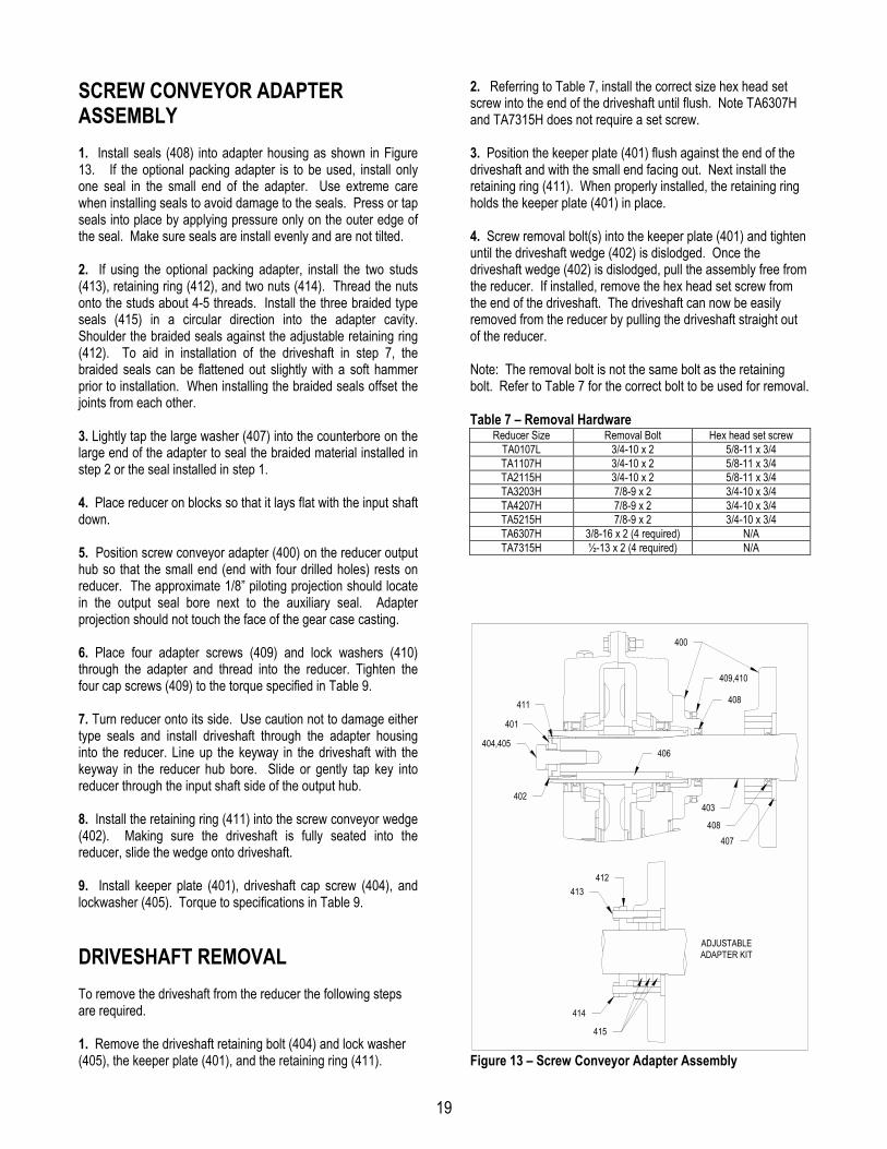
SCREW CONVEYOR ADAPTERASSEMBLY1. Install seals (408) into adapter housing as shown in Figure13. If the optional packing adapter is to be used, install onlyone seal in the small end of the adapter. Use extreme carewhen installing seals to avoid damage to the seals. Press or tapseals into place by applying pressure only on the outer edge ofthe seal. Make sure seals are install evenly and are not tilted.
2. If using the optional packing adapter, install the two studs(413), retaining ring (412), and two nuts (414). Thread the nutsonto the studs about 4-5 threads. Install the three braided typeseals (415) in a circular direction into the adapter cavity.Shoulder the braided seals against the adjustable retaining ring(412). To aid in installation of the driveshaft in step 7, thebraided seals can be flattened out slightly with a soft hammerprior to installation. When installing the braided seals offset thejoints from each other.
3. Lightly tap the large washer (407) into the counterbore on thelarge end of the adapter to seal the braided material installed instep 2 or the seal installed in step 1.
4. Place reducer on blocks so that it lays flat with the input shaftdown.
5. Position screw conveyor adapter (400) on the reducer outputhub so that the small end (end with four drilled holes) rests onreducer. The approximate 1/8” piloting projection should locatein the output seal bore next to the auxiliary seal. Adapterprojection should not touch the face of the gear case casting.
6. Place four adapter screws (409) and lock washers (410)through the adapter and thread into the reducer. Tighten thefour cap screws (409) to the torque specified in Table 9.
7. Turn reducer onto its side. Use caution not to damage eithertype seals and install driveshaft through the adapter housinginto the reducer. Line up the keyway in the driveshaft with thekeyway in the reducer hub bore. Slide or gently tap key intoreducer through the input shaft side of the output hub.
8. Install the retaining ring (411) into the screw conveyor wedge(402). Making sure the driveshaft is fully seated into thereducer, slide the wedge onto driveshaft.
9. Install keeper plate (401), driveshaft cap screw (404), andlockwasher (405). Torque to specifications in Table 9.
DRIVESHAFT REMOVALTo remove the driveshaft from the reducer the following stepsare required.
1. Remove the driveshaft retaining bolt (404) and lock washer(405), the keeper plate (401), and the retaining ring (411).
2. Referring to Table 7, install the correct size hex head setscrew into the end of the driveshaft until flush. Note TA6307Hand TA7315H does not require a set screw.
3. Position the keeper plate (401) flush against the end of thedriveshaft and with the small end facing out. Next install theretaining ring (411). When properly installed, the retaining ringholds the keeper plate (401) in place.
4. Screw removal bolt(s) into the keeper plate (401) and tightenuntil the driveshaft wedge (402) is dislodged. Once thedriveshaft wedge (402) is dislodged, pull the assembly free fromthe reducer. If installed, remove the hex head set screw fromthe end of the driveshaft. The driveshaft can now be easilyremoved from the reducer by pulling the driveshaft straight outof the reducer.
Note: The removal bolt is not the same bolt as the retainingbolt. Refer to Table 7 for the correct bolt to be used for removal.
Table 7 – Removal HardwareReducer Size Removal Bolt Hex head set screw
TA0107L 3/4-10 x 2 5/8-11 x 3/4TA1107H 3/4-10 x 2 5/8-11 x 3/4TA2115H 3/4-10 x 2 5/8-11 x 3/4TA3203H 7/8-9 x 2 3/4-10 x 3/4TA4207H 7/8-9 x 2 3/4-10 x 3/4TA5215H 7/8-9 x 2 3/4-10 x 3/4TA6307H 3/8-16 x 2 (4 required) N/ATA7315H ½-13 x 2 (4 required) N/A
ADJUSTABLEADAPTER KIT
400
404,405
401
411
402
409,410
408
407408
403
406
412413
415
414
Figure 13 – Screw Conveyor Adapter Assembly

20
REPLACEMENT OF PARTSIMPORTANT: Using tools normally found in a maintenancedepartment, a Dodge Torque-Arm II speed reducer can bedisassembled and reassembled by careful attention to theinstructions following.
Cleanliness is very important to prevent the introduction of dirtinto the bearings and other parts of the reducer. A tank of cleansolvent, an arbor press, and equipment for heating bearings andgears (for shrinking these parts on shafts) should be available.
Our factory is prepared to repair reducers for customers who donot have proper facilities or who, for any reason, desire factoryservice.The oil seals are contact lip seals. Considerable care should beused during disassembly and reassembly to avoid damage tothe surface on which the seals rub.
The keyseat in the input shaft, as well as any sharp edges onthe output hub should be covered with tape or paper beforedisassembly or reassembly. Also, be careful to remove anyburrs or nicks on surfaces of the input shaft or output hub beforedisassembly or reassembly.
Ordering Parts: When ordering parts for reducer, specifyreducer size number, reducer model number, part name, partnumber, and quantity.
It is strongly recommended that, when a pinion or gear isreplaced, the mating pinion or gear is replaced also.If the large gear on the output hub must be replaced, it isrecommended that an output hub assembly consisting of a gearassembled on a hub be ordered to ensure undamaged surfaceson the output hub where the output seals rub. However, if it isdesired to use the old output hub, press the gear and bearing offand examine the rubbing surface under the oil seal carefully forpossible scratching or other damage resulting from the pressingoperation. To prevent oil leakage at the shaft oil seals, thesmooth surface of the output hub must not be damaged.
If any parts must be pressed from a shaft or from the outputhub, this should be done before ordering parts to make sure thatnone of the bearings or other parts are damaged in removal. Donot press against rollers or cage of any bearing.
Because old shaft oil seals may be damaged in disassembly, itis advisable to order replacements for these parts.
Removing Reducer from Shaft:
WARNING: To ensure that drive is not unexpectedly started,turn off and lock out or tag power source before proceeding.Remove all external loads from drive before removing orservicing drive or accessories. Failure to observe theseprecautions could result in bodily injury.
Taper Bushed:
1. Disconnect and remove belt guard, v-drive, and motor mountas required. Disconnect torque arm rod from reducer adapter.
2. Remove bushing screws.
3. Place the screws in the threaded holes provided in thebushing flanges. Tighten the screws alternately and evenly untilthe bushings are free on the shaft. For ease of tighteningscrews, make sure screw threads and threaded holes in bushingflanges are clean. A tap can be used to clean out the threads.Use caution to use the proper size tap to prevent damage to thethreads.
4. Remove the outside bushing, the reducer, and then theinboard bushing.
Disassembly:
1. Drain all oil from the reducer.
2. Position the reducer on its side and remove all housing bolts.Drive dowel pins from housing. Using the three pry slots aroundthe periphery of the flange, gently separate the housing halves..Open housing evenly to prevent damage to the parts inside.
3. Lift input shaft, all gear assemblies, and bearing assembliesfrom housing.
4. Remove seals from housing.
5. Remove bearings from shafts and hubs. Be careful not toscratch or damage any assembly or seal area during bearingremoval. The hub assembly can be disassembled for gearreplacement but if scratching or grooving occurs on the hub,seal leakage will occur and the hub will need to be replaced.
Reassembly:
1. Output Hub Assembly: Heat gear to 325°F to 350°F toshrink onto hub. Heat bearings to 270°F to 290°F to shrink ontohub. Any injury to the hub surfaces where the oil seals rub willcause leakage, making it necessary to use a new hub.
2. Countershaft Assembly: Shaft and pinion are integral. Pressgear and bearings on shaft. Press against inner race (not cageor rollers) of bearings.
3. Input Shaft Assembly: Shaft and pinion are integral. Pressbearings on shaft. Press against inner race (not cage or rollers)of bearings.
4. Drive the two dowel pins into place in the right-hand housinghalf.
5. Place R.H. housing half on blocks to allow for protruding endof output hub.
21
6. Install bearing cups in right-hand housing half, making surethey are properly seated. The output hub assembly has onebearing pressed against the gear and the other bearing pressedagainst a shoulder on the hub. For double reduction reducers,install the output hub assembly so that the end where thebearing is pressed against the gear is up. For single reductionreducers, install the output hub assembly so that the end wherethe bearing is pressed against the gear is down.
7. Mesh output hub gear and small countershaft gear togetherand set in place in housing. Set input shaft assembly in place inthe housing. Make sure bearing rollers (cones) are properlyseated in their cups. Set bearing cups for left-hand housing halfin place on their rollers.
8. Making sure both housing halves are clean, set left-handhousing half into position and tap with a soft hammer (rawhide,not lead hammer) until housing bolts can be used to drawhousing halves together. Make sure reducer shafts do not bindwhile tightening housing bolts.
9. Rotate the input shaft and seat all bearings with a softhammer. Using a magnetic base and indicator, measure andrecord the endplay of the input shaft, countershaft, and outputhub. Remove left housing half and shim behind the bearing cupas required to achieve the correct bearing end play or preloadper Table 8. Repeat this process and check endplay untilproper endplay is obtained. Note that the output shaft ispreloaded. After endplay is determined, add the correct shimthickness to the endplay reading to obtain the correct preload.
10. Remove left housing half and clean housing flange surfaceson both halves, making sure not to nick or scratch flange face.Place a 1/8" bead of Dow RTV732 sealant or equivalent onflange face (make sure RTV is placed around bolt holes andinside of flange face). Place left housing half into position andtap with a soft hammer (rawhide, not lead hammer) until housingbolts can be used to draw housing halves together. Torquehousing bolts per torque values listed in Table 9.
11. Install input seal, output seals, and auxiliary seals. Extremecare should be used when installing seals to avoid damage dueto contact with sharp edges on the input shaft or output hub.The possibility of damage and consequent oil leakage can bedecreased by covering all sharp edges with tape prior to sealinstallation. Lightly coat the seal lips with Mobilith AW2 All-Purpose grease or equivalent. Seals should be pressed ortapped with a soft hammer evenly into place in the reducerhousing, applying pressure only on the outer edge of the seals.A slight oil leakage at the seals may be evident during initialrunning, but should disappear unless seals have beendamaged.
12. Install bushing backup plates and snap rings on TaperBushed reducers or hub collars on straight bore reducers.
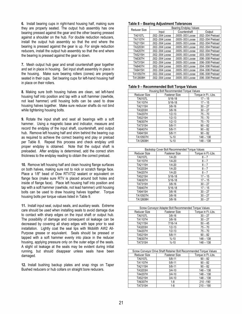
Table 8 – Bearing Adjustment TolerancesBearing Endplay ValuesReducer Size Input Countershaft Output
TA0107L .002-.004 Loose .0005-.003 Loose .002-.004 PreloadTA1107H .002-.004 Loose .0005-.003 Loose .002-.004 PreloadTA2115H .002-.004 Loose .0005-.003 Loose .002-.004 PreloadTA3203H .002-.004 Loose .0005-.003 Loose .002-.004 PreloadTA4207H .002-.004 Loose .0005-.003 Loose .002-.004 PreloadTA5215H .002-.004 Loose .0005-.003 Loose .003-.005 PreloadTA6307H .002-.004 Loose .0005-.003 Loose .006-.008 PreloadTA7315H .002-.004 Loose .0005-.003 Loose .006-.008 PreloadTA8407H .002-.004 Loose .0005-.003 Loose .004-.006 PreloadTA9415H .002-.004 Loose .0005-.003 Loose .004-.006 PreloadTA10507H .002-.004 Loose .0005-.003 Loose .006-.008 PreloadTA12608H .002-.004 Loose .0005-.003 Loose .006-.008 Preload
Table 9 – Recommended Bolt Torque ValuesHousing Bolt Recommended Torque Values
Reducer Size Fastener Size Torque in Ft..-Lbs.TA0107L 5/16-18 17 – 15TA1107H 5/16-18 17 – 15TA2115H 3/8-16 30 – 27TA3203H 3/8-16 30 – 27TA4207H 1/2-13 75 – 70TA5215H 1/2-13 75 – 70TA6307H 1/2-13 75 – 70TA7315H 5/8-11 90 – 82TA8407H 5/8-11 90 – 82TA9415H 5/8-11 90 – 82TA10507H ¾-10 148 – 138TA12608H ¾-10 148 – 138
Backstop Cover Bolt Recommended Torque ValuesReducer Size Fastener Size Torque in Ft.-Lbs.
TA0107L 1/4-20 8 – 7TA1107H 1/4-20 8 – 7TA2115H 1/4-20 8 – 7TA3203H 1/4-20 8 – 7TA4207H 1/4-20 8 – 7TA5215H 5/16-18 17 – 15TA6307H 5/16-18 17 – 15TA7315H 3/8-16 30 – 27TA8407H 5/16-18 17 – 15TA9415H 3/8-16 30 – 27TA10507H 3/8-16 30 – 27TA12608H 3/8-16 30 – 27
Screw Conveyor Adapter Bolt Recommended Torque ValuesReducer Size Fastener Size Torque in Ft.-Lbs.
TA0107L 3/8-16 30 – 27TA1107H 3/8-16 30 – 27TA2115H 7/16-14 50 – 45TA3203H 1/2-13 75 – 70TA4207H 1/2-13 75 – 70TA5215H 5/8-11 90 – 82TA6307H ¾-10 148 – 138TA7315H ¾-10 148 – 138
Screw Conveyor Drive Shaft Retainer Bolt Recommended Torque ValuesReducer Size Fastener Size Torque in Ft.-Lbs.
TA0107L 5/8-11 90 – 82TA1107H 5/8-11 90 – 82TA2115H 5/8-11 90 – 82TA3203H 3/4-10 148 – 138TA4207H 3/4-10 148 – 138TA5215H 3/4-10 148 – 138TA6307H 1-8 210 –190TA7315H 1-8 210 – 190

22
REPLACEMENT PART AND KITNUMBERSTable 10–Dodge and Timken Part Numbers for ReplacementBearings, Single and Double Reduction Reducers
Output Hub Bearing – LH and RH SidesReducerSize Dodge Part Number Timken Part Number
TA0107L 900250/900251 LM104911/LM104949TA1107H 901250/901251 382A/387ATA2115H 403003/402003 JLM714110/JLM714149TA3203H 903252/402268 493/498TA4207H 403016/402193 42584/42381TA5215H 403140/402050 JM822010/JM822049TA6307H 906250/906251 68712/68462TA7315H 403105/402147 36620/36690TA8407H 403105/402147 36620/36690TA9415H 403110/402160 46720/46790TA10507H 910250/910251 JM738210/JM38249TA12608H 912250/912251 LM742710/LM742749
Countershaft Bearing – LH SideReducerSize Dodge Part Number Timken Part Number
TA0107L 304833/304740 LM11710/LM11749TA1107H 403165/402265 LM11910/LM11949TA2115H 304836/411626-05-B M12610/M12649TA3203H 403101/402271 02820/02872TA4207H 304809/304710 25821/25877TA5215H 403005/402001 3820/3877TA6307H 403026/906257 45220/45280TA7315H 403159/907260 HM807010/HM807046TA8407H 411626-06-BE/411626-05-BM 65500/65237TA9415H 403036/304701 6320/6379TA10507H 403087/402023 6420/6461TA12608H 402233/912253 HH221410/HH221434
Countershaft Bearing – Backstop (RH) SideReducerSize Dodge Part Number Timken Part Number
TA0107L 304833/304740 LM11710/LM11749TA1107H 403165/402265 LM11910/LM11949TA2115H 304836/411626-05-B M12610/M12649TA3203H 403101/402271 02820/02872TA4207H 304809/304710 25821/25877TA5215H 403005/402001 3820/3877TA6307H 403026/906257 45220/45280TA7315H 403159/907260 HM807010/HM807046TA8407H 411626-06-BE/908253 65500/65200TA9415H 403036/304701 6320/6379TA10507H 403087/402023 6420/6461TA12608H 402233/912253 HH221410/HH221434
Input Shaft Bearing – LH SideReducerSize Dodge Part Number Timken Part Number
5:19:115:125:1
TA0107L
40:1
403165/402265 LM11910/LM11949
5:19:115:1
403063/411626-05-AY 09195/09081
25:1TA1107H
40:1 403063/402108 09195/09067
5:19:115:125:1
403094/304753 15245/15113TA2115H
40:1 403094/304707 15245/151015:19:115:125:1
304809/411626-05-K 25821/25880TA3203H
40:1 403101/402271 02820/028725:19:115:125:1
TA4207H
40:1
304809/411626-05-K 25821/25880
5:19:115:1
403005/402001 3820/3877
25:1TA5215H
40:1 403005/304717 3820/3880
5:19:115:125:1
TA6307H
40:1
403026/906260 45220/45290
5:19:115:125:1
TA7315H
40:1
304802/402041 HM212011/HM212049
15:125:1TA8407H40:1
908259/908260 H414210/H414242
15:125:1TA9415H40:1
403036/304701 6320/6379
15:125:1TA10507H40:1
402231/402232 JH415610/JH415647
15:125:1TA12608H40:1
402231/402232 JH415610/JH415647
23
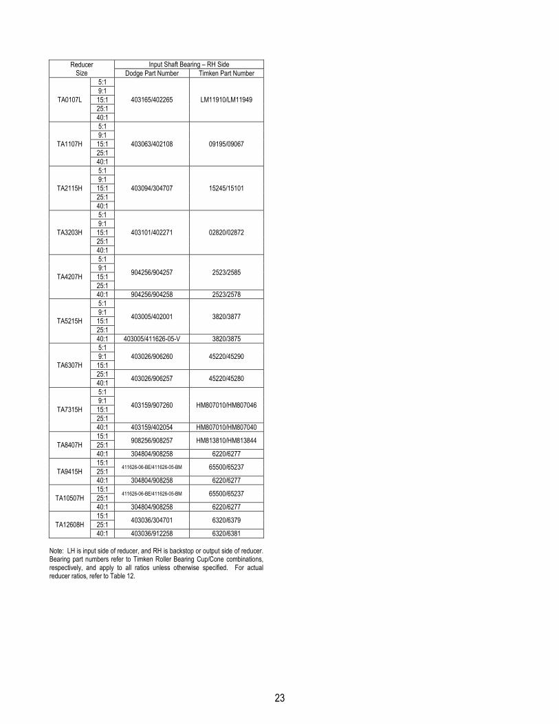
Input Shaft Bearing – RH SideReducerSize Dodge Part Number Timken Part Number
5:19:115:125:1
TA0107L
40:1
403165/402265 LM11910/LM11949
5:19:115:125:1
TA1107H
40:1
403063/402108 09195/09067
5:19:115:125:1
TA2115H
40:1
403094/304707 15245/15101
5:19:115:125:1
TA3203H
40:1
403101/402271 02820/02872
5:19:115:125:1
904256/904257 2523/2585TA4207H
40:1 904256/904258 2523/25785:19:115:125:1
403005/402001 3820/3877TA5215H
40:1 403005/411626-05-V 3820/38755:19:115:1
403026/906260 45220/45290
25:1TA6307H
40:1 403026/906257 45220/45280
5:19:115:125:1
403159/907260 HM807010/HM807046TA7315H
40:1 403159/402054 HM807010/HM80704015:125:1 908256/908257 HM813810/HM813844TA8407H40:1 304804/908258 6220/627715:125:1 411626-06-BE/411626-05-BM 65500/65237TA9415H40:1 304804/908258 6220/627715:125:1 411626-06-BE/411626-05-BM 65500/65237TA10507H40:1 304804/908258 6220/627715:125:1 403036/304701 6320/6379TA12608H40:1 403036/912258 6320/6381
Note: LH is input side of reducer, and RH is backstop or output side of reducer.Bearing part numbers refer to Timken Roller Bearing Cup/Cone combinations,respectively, and apply to all ratios unless otherwise specified. For actualreducer ratios, refer to Table 12.

24
Table 11 – Replacement Parts Kit NumbersReducer Size Ratio Seal Kit Output Hub Assembly Countershaft Assembly Bearing Kit
5:1 --- 9001289:1 90012215:1 90012325:1 900124
TA0107L
40:1
900126 900120
900125
900129
5:1 --- 9011289:1 90112215:1 901123 901129
25:1 901124TA1107H
40:1
901126 901120
901125 901130
5:1 --- 9021289:1 90212215:1 90212325:1
902126
902124902129TA2115H
40:1 902127
902120
902125 9021305:1 --- 9031289:1 90312215:1 90312325:1
903126
903124903129TA3203H
40:1 903127
903120
903125 9031305:1 --- 9041289:1 90412215:1 90412325:1 904124
904129TA4207H
40:1
904126 904120
904125 9041305:1 --- 9051289:1 90512215:1 905123 905129
25:1 905124 905130TA5215H
40:1
905126 905120
905125 9051315:1 --- 9061289:1 90612215:1 906123 906129
25:1 906124TA6307H
40:1
906126 906120
906125 906130
5:1 --- 9071289:1 90712215:1 90712325:1 907124
907129TA7315H
40:1
907126 907120
907125 90713015:1 90812325:1 908124 908129TA8407H40:1
908126 908120908125 908130
15:1 90912325:1 909124 909129TA9415H40:1
909126 909120909125 909130
15:1 91012325:1 910124 910129TA10507H40:1
910126 910120910125 910130
15:1 91212325:1 912124 912129TA12608H40:1
912126 912120912125 912130
Seal Kit consists of Input Seal, Output Seals, Backstop Cover Gasket and RTV Sealant.Output Hub Assembly consists of Output Hub, Output Gear and Gear Key.Countershaft Assembly consists of Countershaft Pinion, Countershaft Gear and Gear Key.Bearing Kit consists of LH and RH Output Bearing Cup/Cone, LH and RH Countershaft Bearing Cup/Cone (double reduction only) and LH and RH Input Bearing Cup/Cone.

25
Parts for TA0107L thru TA12608H Taper Bushed Double Reduction Reducers
106,108,109,110
101
104
103
105107
111,112
600
10031,33
11,12
9
18
22
13
45
30,32
29
28
OPTIONALBACKSTOPASSEMBLY
TORQUE-ARMASSEMBLY
10
34,3641
4414
24,25
21
40
39
35,37
204,205
201,202
203
200
38
27
26
234,5,6,7
15,16
1
2
102
SCREW CONVEYORADAPTER ASSEMBLY
ADJUSTABLEADAPTER KIT
400
404,405
401
411
402
409,410
408
407408
403
406
412413
415
414

26
Parts for TA0107L thru TA7315H Taper Bushed Single Reduction Reducers
600
31,33
11,12
9
18
22
13
45
30,32
OPTIONALBACKSTOPASSEMBLY
10
4414
21
26
4,5,6,715,16
1
106,108,109,110
101
104
103
105107
111,112
100
29
28
TORQUE-ARMASSEMBLY
24,25
204,205
201,202
203
200
27
23 2
102
SCREW CONVEYORADAPTER ASSEMBLY
ADJUSTABLEADAPTER KIT
400
404,405
401
411
402
409,410
408
407408
403
406
412413
415
414

27
Parts for TA0107L thru TA5215H Taper Bushed Double and Single Reduction Reducers
Ref. Description Qty. TA0107L TA1107H TA2115H TA3203H TA4207H TA5215H
1 Housing-LH 1 900202 901202 902202 903202 904202 9052022 Housing-RH 1 900203 901203 902203 903203 904203 905203§ RTV Sealant, Tube 1 465044 465044 465044 465044 465044 4650444 Housing Bolt 14 411253 411253 411412 411412 411460 4114605 Flat Washer 28 900241 900241 902241 902241 904241 9042416 Nut 14 407085 407085 407087 407087 407091 4070917 Lock-Washer 14 419010 419010 419011 419011 419013 419013
8 § Dowel Pin 2 901248 901248 304624 901248 304624 3046249 Backstop Shaft Cover 1 901279 901279 901279 903279 904279 905279
10 Backstop Cover Gasket 1 901280 901280 901280 903280 904280 90528011 Backstop Cover Screw 6 � 417038 417038 417038 417038 417038 41707412 Lock-Washer 6 � 419045 419045 419045 419045 419045 41904613 Input Oil Seal
5:1, 9:1, 15:1 � 1 901235 901235 902235 304924 244524 30493225:1 Ratio � 1 901235 901235 902235 304924 244524 30493240:1 Ratio � 1 901235 901235 902233 903235 244524 304932
14 Output Oil Seal 2 900234 352122 243578 244673 245545 24631015 Air Vent 1 241237 241237 241237 241237 245237 24523716 Bushing 1 N/A N/A N/A N/A 430079 430079
17 § Oil Plug 4 430031 430031 430031 430031 430035 43003518 Magnetic Oil Plug 1 430060 430060 430060 430060 430064 43006421 Output Bearing Shim-As Req’d
.015” Shim 900263 901263 902263 903263 904263 905263
.007” Shim 900265 901265 902265 903265 904265 905265
.005” Shim 900264 901264 902264 903264 904264 90526422 Input Bearing Shim-As Req’d
.015” Shim 901267 901271 902271 903267 903267 905271
.007” Shim 901269 901273 902273 903269 903269 905273
.005” Shim 901268 901272 902272 903268 903268 90527241 Counter-Shaft Bearing Shim-As Req’d
.015” Shim 900267 901267 901271 903267 903267 905271
.007” Shim 900269 901269 901273 903269 903269 905273
.005” Shim 900268 901268 901272 903268 903268 90527223 Output Gear 1 900208 901208 902208 903208 904208 90520826 Output Hub 1 900230 901230 902230 903230 904230 90523027 Output Gear Key 1 900275 901275 901275 903275 904275 90527528 Input Pinion Key
5:1, 9:1, 15:1, 25:1 Ratio � 1 901277 901277 902277 903277 904277 90527740:1 Ratio � 1 901277 901277 902277 903298 904277 905277
29 Input Pinion5:1 Ratio � 1 900222 901222 902222 903222 904222 9052229:1 Ratio � 1 900221 901221 902221 903221 904221 90522115:1 Ratio � 1 900220 901220 902220 903220 904220 90522025:1 Ratio � 1 900219 901219 902219 903219 904219 90521940:1 Ratio � 1 900218 901218 902218 903218 904218 905218
38 First Stage Gear9:1 Ratio � 1 900217 901217 902217 903217 904217 90521715:1 Ratio � 1 900215 901215 902215 903215 904215 90521525:1 Ratio � 1 900213 901213 902213 903213 904213 90521340:1 Ratio � 1 900211 901211 902211 903211 904211 905211
39 Counter-Shaft Pinion 1 900209 901209 902209 903209 904209 90520940 First Stage Gear Key 1 900276 901276 902276 903276 904276 905276600 Backstop Assembly
5:1, 9:1, 15:1, 25:1 Ratio �40:1 Ratio �
11
901102901102
901102901102
902102902102
903102903102
904102904103
905102905103
100 Torque-Arm Adapter Bracket 2 900500 901500 902500 903500 904500 905500Torque-Arm Rod Kit � 1 241244 241244 242244 242244 244245 244245
101 � Torque-Arm Rod End 1 241245 241245 243245 243245 245245 245245102 � Torque-Arm Extension 1 241247 241247 243247 243247 245247 245247103 � Torque-Arm Turnbuckle 1 241246 241246 243246 243246 245246 245246104 � RH Nut 1 407093 407093 407095 407095 407097 407097105 � LH Nut 1 407242 407242 407244 407244 407246 407246106 Torque-Arm Bushing 1 242243 242243 243243 243243 245243 245243107 Torque-Arm Fulcrum 1 241249 241249 243249 243249 246249 246249108 Torque-Arm Bolt 1 411412 411412 411437 411437 411460 411460109 Torque-Arm Lock-Washer 1 419011 419011 419012 419012 419013 419013
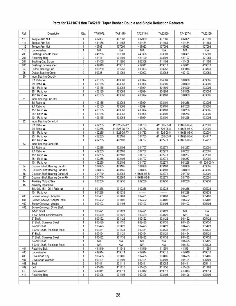
28
Parts for TA1107H thru TA5215H Taper Bushed Double and Single Reduction Reducers
Ref. Description Qty. TA0107L TA1107H TA2115H TA3203H TA4207H TA5215H
110 Torque-Arm Nut 1 407087 407087 407089 407089 407091 407091111 Torque-Arm Bolt 1 411456 411456 411484 411484 411484 411484112 Torque-Arm Nut 1 407091 407091 407093 407093 407093 407093113 Lock-washer 1 N/A N/A N/A N/A N/A N/A200 Bushing Back-Up Plate 2 241266 901301 243308 903301 904301 905301203 Retaining Ring 2 421111 901304 421109 903304 421107 421055204 Bushing Cap Screw 6 411405 411390 902306 411408 411408 411456205 Bushing Lock-Washer 6 419010 419010 419011 419011 419011 41901324 Output Bearing Cup 2 900250 901250 403003 903252 403016 40314025 Output Bearing Cone 2 900251 901251 402003 402268 402193 40205030 Input Bearing Cup-LH
5:1 Ratio � 1 403165 403063 403094 304809 304809 4030059:1 Ratio � 1 403165 403063 403094 304809 304809 40300515:1 Ratio � 1 403165 403063 403094 304809 304809 40300525:1 Ratio � 1 403165 403063 403094 304809 304809 40300540:1 Ratio � 1 403165 403063 403094 403101 304809 403005
31 Input Bearing Cup-RH5:1 Ratio � 1 403165 403063 403094 403101 904256 4030059:1 Ratio � 1 403165 403063 403094 403101 904256 40300515:1 Ratio � 1 403165 403063 403094 403101 904256 40300525:1 Ratio � 1 403165 403063 403094 403101 904256 40300540:1 Ratio � 1 403165 403063 403094 403101 904256 403005
32 Input Bearing Cone-LH5:1 Ratio � 1 402265 411626-05-AY 304753 411626-05-K 411626-05-K 4020019:1 Ratio � 1 402265 411626-05-AY 304753 411626-05-K 411626-05-K 40200115:1 Ratio � 1 402265 411626-05-AY 304753 411626-05-K 411626-05-K 40200125:1 Ratio � 1 402265 402108 304753 411626-05-K 411626-05-K 30471740:1 Ratio � 1 402265 402108 304707 402271 411626-05-K 304717
33 Input Bearing Cone-RH5:1 Ratio � 1 402265 402108 304707 402271 904257 4020019:1 Ratio � 1 402265 402108 304707 402271 904257 40200115:1 Ratio � 1 402265 402108 304707 402271 904257 40200125:1 Ratio � 1 402265 402108 304707 402271 904257 40200140:1 Ratio � 1 402265 402108 304707 402271 904258 411626-05-V
34 Counter-Shaft Bearing Cup-LH 1 304833 403165 304836 403101 304809 40300535 Counter-Shaft Bearing Cup-RH 1 304833 403165 304836 403101 304809 40300536 Counter-Shaft Bearing Cone-LH 1 304740 402265 411626-05-B 402271 304710 40200137 Counter-Shaft Bearing Cone-RH 1 304740 402265 411626-05-B 402271 304710 40200144 Auxiliary Output Seal 2 900236 901236 902236 903236 904236 90523645 Auxiliary Input Seal
5:1, 9:1, 15:1, 25:1 Ratio � 1 901238 901238 902238 903238 904238 90523840:1 Ratio � 1 901238 901238 -------- -------- 904238 905238
400 Screw Conveyor Adapter 1 900401 901401 902401 903401 904401 905401401 Screw Conveyor Keeper Plate 1 900402 901402 902402 903402 904402 905402402 Screw Conveyor Wedge 1 900403 901403 902403 903403 904403 905403403 Screw Conveyor Drive Shaft
1-1/2” Shaft 1 900421 901421 902421 903421 N/A N/A1-1/2” Shaft, Stainless Steel 1 900429 901429 902429 903429 N/A N/A2” Shaft 1 900422 901422 902422 903422 904422 9054222” Shaft, Stainless Steel 1 900430 901430 902430 903430 904430 9054302-7/16” Shaft 1 900423 901423 902423 903423 904423 9054232-7/16” Shaft, Stainless Steel 1 900431 901431 902431 903431 904431 9054313” Shaft 1 900424 901424 902424 903424 904424 9054243” Shaft, Stainless Steel 1 900432 901432 902432 903432 904432 9054323-7/16” Shaft 1 N/A N/A N/A N/A 904425 9054253-7/16” Shaft, Stainless Steel 1 N/A N/A N/A N/A 904433 905433
404 Retaining Bolt 1 411549 411549 411549 411551 411551 411551405 Lock-Washer 1 419014 419014 419014 419016 419016 419016406 Drive Shaft Key 1 900405 901405 902405 903405 904405 905405407 Drive Shaft Washer 1 900404 901404 902404 903404 904404 905404408 Seal 2 901411 901411 902411 353085 904411 905411409 Bolt 4 411410 411410 411435 411456 411456 411483410 Lock-Washer 4 419011 419011 419012 419013 419013 419014411 Retaining Ring 1 900406 901406 902406 903406 904406 905406

29
Parts for TA0107L thru TA5215H Taper Bushed Double and Single Reduction Reducers
Ref. Description Qty. TA0107L TA1107H TA2115H TA3203H TA4207H TA5215H
412 Adjustable Packing Retainer 1 900413 901413 902413 903413 904413 905413413 Adjustable Packing Gland Stud 2 400404 400404 400404 400404 400404 400404414 Adjustable Packing Gland Nut 2 407202 407202 407202 407202 407202 407202415 Sealing Rings 3 900416 901416 902416 903416 904416 905416
Notes:§ Not shown on drawing.� Includes parts listed immediately below marked “�”.� Makes up assembly under which it is listed.� 8 required on TA5215H.� See Table 12 for actual ratio.

30
Parts for TA6307H thru TA12608H Taper Bushed Double and Single Reduction Reducers
Ref. Description Qty. TA6307H TA7315H TA8407H TA9415H TA10507 TA12608
1 Housing-LH 1 906202 907202 908202 909202 910202 9122022 Housing-RH 1 906203 907203 908203 909203 910203 912203§ RTV Sealant, Tube 1 465044 465044 465044 465044 465044 4650444 Housing Bolt 14 � 411460 411488 411488 411488 411496 4114965 Flat Washer 28 � 904241 907241 907241 907241 910241 9102416 Nut 14 � 407091 407093 407093 407093 407095 4070957 Lock-Washer 14 � 419013 419014 419014 419014 419016 419016
8 § Dowel Pin 2 304624 304624 304624 304624 304624 3046249 Backstop Shaft Cover 1 906279 907279 908279 907279 910279 912279
10 Backstop Cover Gasket 1 906280 907280 908280 907280 910280 91228011 Backstop Cover Screw 6 � 417074 907281 417074 907281 907281 90728112 Lock-Washer 6 � 419046 419047 419046 419047 419047 41904713 Input Oil Seal
5:1, 9:1 � 1 352122 242210 N/A N/A N/A N/A15:1 � 1 352122 242210 242210 242210 243578 24357825:1 Ratio � 1 352122 242210 242210 242210 243578 24357840:1 Ratio � 1 352122 242210 242210 242210 243578 243578
14 Output Oil Seal 2 906234 258019 258019 909234 910234 91223415 Air Vent 1 245237 245237 245237 245237 245237 24523716 Bushing 1 430079 430079 430079 430079 430079 430079
17 § Oil Plug 4 430035 430035 430035 430035 430035 43003518 Magnetic Oil Plug 1 430064 430064 430064 430064 430064 43006421 Output Bearing Shim-As Req’d
.015” Shim 906263 907263 907263 909263 910263 912263
.007” Shim 906265 907265 907265 909265 910265 912265
.005” Shim 906264 907264 907264 909264 910264 91226422 Input Bearing Shim-As Req’d
.015” Shim 906271 907271 903263 909267 910267 910267
.007” Shim 906273 907273 903265 909269 910269 910269
.005” Shim 906272 907272 903264 909268 910268 91026841 Counter-Shaft Bearing Shim-As Req’d
.015” Shim 906271 906271 908267 909267 904263 912267
.007” Shim 906273 906273 908269 909269 909265 912269
.005” Shim 906272 906272 908268 909268 904264 91226823 Output Gear 1 906208 907208 908208 909208 910208 91220826 Output Hub 1 906230 907230 908230 909230 910230 91223027 Output Gear Key 1 � 906275 907275 908275 909275 910275 91227528 Input Pinion Key
5:1, 9:1 � 1 906277 907277 N/A N/A N/A N/A15:1, 25:1 Ratio � 1 906277 907277 908277 909277 909277 90927740:1 Ratio � 1 906277 907277 908277 909277 909277 909277
29 Input Pinion5:1 Ratio � 1 906222 907222 N/A N/A N/A N/A9:1 Ratio � 1 906221 907221 N/A N/A N/A N/A15:1 Ratio � 1 906220 907220 908220 909220 910220 91222025:1 Ratio � 1 906219 907219 908219 909219 910219 91221940:1 Ratio � 1 906218 907218 908218 909218 910218 912218
38 First Stage Gear9:1 Ratio � 1 906217 907217 N/A N/A N/A N/A15:1 Ratio � 1 906215 907215 908215 909215 910215 91221525:1 Ratio � 1 906213 907213 908213 909213 910213 91221340:1 Ratio � 1 906211 907211 908211 909211 910211 912211
39 Counter-Shaft Pinion 1 906209 907209 908209 909209 910209 91220940 First Stage Gear Key 1 906276 907276 908276 909276 910276 912276600 Backstop Assembly
5:1, 9:1 � 1 906102 907102 N/A N/A N/A N/A15:1 Ratio � 1 906102 907102 908102 909102 910102 91210225:1 Ratio � 1 906103 907102 908102 909102 910102 91210240:1 Ratio � 1 906103 907103 908103 907103 910103 912103
100 Torque-Arm Adapter Bracket 2 906500 907500 907500 909500 910500 912500Torque-Arm Rod Kit � 1 247238 248240 248240 272416 272416
101 � Torque-Arm Rod End 1 247239 271050 271050 272050 272050 272151102 � Torque-Arm Extension 1 247240 271052 271052 272052 272052 272153103 � Torque-Arm Turnbuckle 1 247246 271051 271051 272051 272051 272152104 � RH Nut 1 407099 407104 407104 407108 407108 407110

31
Parts for TA6307H thru TA12608H Taper Bushed Double and Single Reduction Reducers
Ref. Description Qty. TA6307H TA7315H TA8407H TA9415H TA10507H TA12608H
105 � LH Nut 1 407248 407250 407250 407251 407251 407111106 Torque-Arm Bushing 1 247244 271046 271046 272046 272046 272187107 Torque-Arm Fulcrum 1 247248 271054 271054 272054 272054 272154108 Torque-Arm Bolt 1 411489 411510 411510 411520 411520 411527109 Torque-Arm Lock-Washer 1 419014 419020 419020 419024 419024 419025110 Torque-Arm Nut 1 407093 407099 407099 407104 407104 407108111 Torque-Arm Bolt 1 411489 411516 411516 419524 411524 411528112 Torque-Arm Nut 1 407093 407099 407099 407104 407104 407108113 Lock-washer 1 419014 419020 419020 419024 419024 419025200 Bushing Back-Up Plate 2 906301 272037 908301 909301 910301 912301203 Retaining Ring 2 906304 421098 908304 909304 910304 912304204 Bushing Cap Screw 6 � 411456 411457 411457 411484 411484 411484205 Bushing Lock-Washer 6 � 419013 419013 419013 419014 419014 41901424 Output Bearing Cup 2 906250 403105 403105 403110 910250 91225025 Output Bearing Cone 2 906251 402147 402147 402160 910251 91225130 Input Bearing Cup-LH
5:1 Ratio � 1 403026 304802 N/A N/A N/A N/A9:1 Ratio � 1 403026 304802 N/A N/A N/A N/A15:1 Ratio � 1 403026 304802 908259 403036 402231 40223125:1 Ratio � 1 403026 304802 908259 403036 402231 40223140:1 Ratio � 1 403026 304802 908259 403036 402231 402231
31 Input Bearing Cup-RH5:1 Ratio � 1 403026 403159 N/A N/A N/A N/A9:1 Ratio � 1 403026 403159 N/A N/A N/A N/A15:1 Ratio � 1 403026 403159 908256 411626-06-BE 411626-06-BE 40303625:1 Ratio � 1 403026 403159 908256 411626-06-BE 411626-06-BE 40303640:1 Ratio � 1 403026 403159 304804 304804 304804 403036
32 Input Bearing Cone-LH5:1 Ratio � 1 906260 402041 N/A N/A N/A N/A9:1 Ratio � 1 906260 402041 N/A N/A N/A N/A15:1 Ratio � 1 906260 402041 908260 304701 402232 40223225:1 Ratio � 1 906260 402041 908260 304701 402232 40223240:1 Ratio � 1 906260 402041 908260 304701 402232 402232
33 Input Bearing Cone-RH5:1 Ratio � 1 906260 907260 N/A N/A N/A N/A9:1 Ratio � 1 906260 907260 N/A N/A N/A N/A15:1 Ratio � 1 906260 907260 908257 411626-05-BM 411626-05-BM 30470125:1 Ratio � 1 906257 907260 908257 411626-05-BM 411626-05-BM 30470140:1 Ratio � 1 906257 402054 908258 908258 908258 912258
34 Counter-Shaft Bearing Cup-LH 1 403026 403159 411626-06-BE 403036 403087 40223335 Counter-Shaft Bearing Cup-RH 1 403026 403159 411626-06-BE 403036 403087 40223336 Counter-Shaft Bearing Cone-LH 1 906257 907260 411626-05-BM 304701 402023 91225337 Counter-Shaft Bearing Cone-RH 1 906257 907260 908253 304701 402023 91225344 Auxiliary Output Seal 2 906236 907236 907236 909236 910236 91223645 Auxiliary Input Seal
5:1, 9:1 Ratio � 1 901236 907238 N/A N/A N/A N/A15:1, 25:1 Ratio � 1 901236 907238 907238 907238 902236 90223640:1 Ratio � 1 901236 907238 907238 907238 902236 902236
400 Screw Conveyor Adapter 1 906401 907401 N/A N/A N/A N/A401 Screw Conveyor Keeper Plate 1 906402 907402 N/A N/A N/A N/A402 Screw Conveyor Wedge 1 906403 907403 N/A N/A N/A N/A403 Screw Conveyor Drive Shaft
2-7/16” Shaft 1 906423 907423 N/A N/A N/A N/A2-7/16” Shaft, Stainless Steel 1 906431 907431 N/A N/A N/A N/A3” Shaft 1 906424 907424 N/A N/A N/A N/A3” Shaft, Stainless Steel 1 906432 907432 N/A N/A N/A N/A3-7/16” Shaft 1 906425 907425 N/A N/A N/A N/A3-7/16” Shaft, Stainless Steel 1 906433 907433 N/A N/A N/A N/A
404 Retaining Bolt 1 411552 411552 N/A N/A N/A N/A405 Lock-Washer 1 419020 419020 N/A N/A N/A N/A406 Drive Shaft Key 1 906405 907405 N/A N/A N/A N/A407 Drive Shaft Washer 1 906404 907404 N/A N/A N/A N/A408 Seal 2 906411 907411 N/A N/A N/A N/A
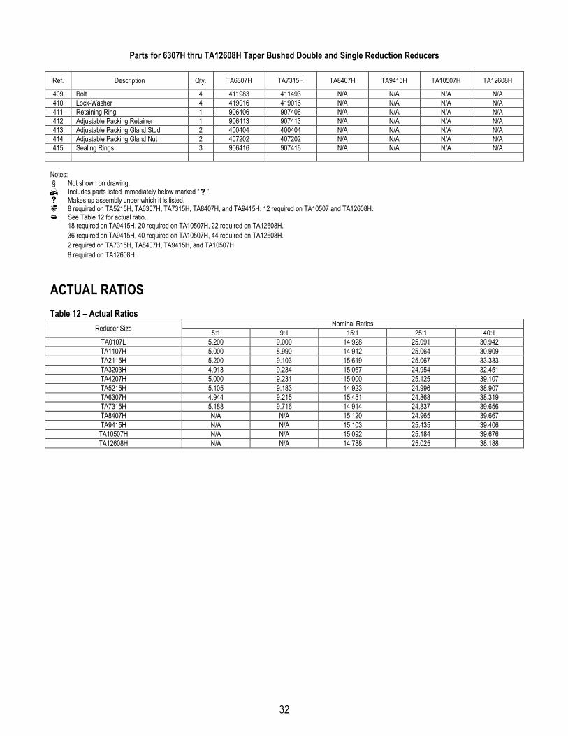
32
Parts for 6307H thru TA12608H Taper Bushed Double and Single Reduction Reducers
Ref. Description Qty. TA6307H TA7315H TA8407H TA9415H TA10507H TA12608H
409 Bolt 4 411983 411493 N/A N/A N/A N/A410 Lock-Washer 4 419016 419016 N/A N/A N/A N/A411 Retaining Ring 1 906406 907406 N/A N/A N/A N/A412 Adjustable Packing Retainer 1 906413 907413 N/A N/A N/A N/A413 Adjustable Packing Gland Stud 2 400404 400404 N/A N/A N/A N/A414 Adjustable Packing Gland Nut 2 407202 407202 N/A N/A N/A N/A415 Sealing Rings 3 906416 907416 N/A N/A N/A N/A
Notes:§ Not shown on drawing.� Includes parts listed immediately below marked “�”.� Makes up assembly under which it is listed.� 8 required on TA5215H, TA6307H, TA7315H, TA8407H, and TA9415H, 12 required on TA10507 and TA12608H.� See Table 12 for actual ratio.�
18 required on TA9415H, 20 required on TA10507H, 22 required on TA12608H.�
36 required on TA9415H, 40 required on TA10507H, 44 required on TA12608H.�
2 required on TA7315H, TA8407H, TA9415H, and TA10507H�
8 required on TA12608H.
ACTUAL RATIOSTable 12 – Actual Ratios
Nominal RatiosReducer Size 5:1 9:1 15:1 25:1 40:1TA0107L 5.200 9.000 14.928 25.091 30.942TA1107H 5.000 8.990 14.912 25.064 30.909TA2115H 5.200 9.103 15.619 25.067 33.333TA3203H 4.913 9.234 15.067 24.954 32.451TA4207H 5.000 9.231 15.000 25.125 39.107TA5215H 5.105 9.183 14.923 24.996 38.907TA6307H 4.944 9.215 15.451 24.868 38.319TA7315H 5.188 9.716 14.914 24.837 39.656TA8407H N/A N/A 15.120 24.965 39.667TA9415H N/A N/A 15.103 25.435 39.406TA10507H N/A N/A 15.092 25.184 39.676TA12608H N/A N/A 14.788 25.025 38.188