Tornillo de Bolas BP-120
69
RA 83 301/07.99 Precision Ball Screw A ssemblies E nd Bear i ngs A nd Housi ngs Rexroth Star
-
Upload
leninpatrick1277 -
Category
Documents
-
view
221 -
download
0
Transcript of Tornillo de Bolas BP-120

7/22/2019 Tornillo de Bolas BP-120
http://slidepdf.com/reader/full/tornillo-de-bolas-bp-120 1/68
RA 83 301/07.99
Precision Ball Screw A ssemblies
End Bearings A nd Housings
Rexroth Star
7/22/2019 Tornillo de Bolas BP-120
http://slidepdf.com/reader/full/tornillo-de-bolas-bp-120 2/682
The Product Range Linear Motion Technology
REG.-NR.
1617 - 01
Deutsche Star GmbH
D-97419 Schweinfurt
Linear Bushings and Shafts Linear Bushings
Linear Sets
ShaftsShaft Support Rails, Shaft Support Blocks
Ball Transfer Units
Other Engineering Components
Profiled Rail Systems Cam Roller Guides
Ball Rail® Systems
Roller Rail TM Systems
Screw Drives Precision Ball Screw Assemblies
End Bearings and Housings
Linear Motion Systems Linear Motion Slides
Linear Modules
Robotic Erector Systems,
Connectors and Mounting Accessories
Compact Slides
Ball Rail® Tables
Components for Customized
Positioning Systems
Controllers
Electrical Accessories, Fittings
Star, Ball Rail and are trademarks
registered for Deutsche Star GmbH, Germany.
Roller Rail is a trademark of
Deutsche Star Gmbh, Germany.
7/22/2019 Tornillo de Bolas BP-120
http://slidepdf.com/reader/full/tornillo-de-bolas-bp-120 3/68 3
Product Overview 4
General 12
Acceptance Conditions and Tolerance Grades 14
Design Notes 18
Design Calculations 20
Preload and Rigidity 24
Mounting and Lubrication Instructions 26
Dimension Tables / Nuts 30
- Single nut with flange DIN 69051, Part 5 FEM-E-C 30- Adjustable-preload single nut DIN 69051, Part 5 SEM-E-C 32
- Single nut with flange FEM-E-S 34
- Adjustable-preload single nut SEM-E-S 36
- Cylindrical single nut ZEM-E-S, ZEM-E-A 38
- Double nut with flange DIN 69051, Part 5 FDM-E-C 40
- Double nut with flange FDM-E-S 42
Dimension Tables / Precision-Rolled Screws 44
End Machining Details 46
End Bearings 48
- Design Calculations 48
- Design Notes 50
- Mounting Instructions 51
Dimension Tables / End Bearings 54
- Fixed bearing ZKLF 54
- Fixed bearing ZKLN 56
- Pillow block unit - fixed bearing ZKLN 58
- Floating bearing DIN 625 60- Pillow block unit - floating bearing DIN 625 62
Dimension Tables / Nut Housings 64
Design Calculation Form 66
Inquiry / Order Form 67
Precision Ball Screw Assemblies
End Bearings and Housings

7/22/2019 Tornillo de Bolas BP-120
http://slidepdf.com/reader/full/tornillo-de-bolas-bp-120 4/684
For nearly 20 years, Precision Ball Screw Assemblies have been
a core product group within the STAR range.
STAR – Precision Ball Screw Assemblies
Product Overview
- precision-rolled screws
- preloaded single nuts
- adjustable-preload single nuts (patented)
Affordable precision-rolled screws replace ground-thread
screws in a wide range of application areas.
Preloaded single nuts with optimized ball size selection or
patented adjustable-preload single nuts are much more cost
efficient than conventional double-nut systems.
Available from stock
STAR ball screws provide technical designers with diverse so-
lutions for positioning and transport tasks. Moreover, affordable
system design is made easy with
The related standards (DIN 69 051 and ISO 3408), though
relatively young by comparison, are fully supported by STAR:for every STAR nut with flange in this catalog you will find a
corresponding design with DIN mounting dimensions.
Single STAR nut units and off-the-shelf precision-rolled screws
guarantee short delivery periods for complete ball screwassemblies.
STAR offers the following product range:
- complete ball screw assemblies
ground-thread or precision-rolled screws combined with any
of the available single or double nuts, with end machining
- precision-rolled screws, optional length,
with soft-annealed ends
for end machining by customer- single nuts supplied on mounting arbor
All single nuts in the version with backlash can be
easily mounted by the customer. In addition, the adjustable-
preload single nut allows the customer to perform preload
adjustment in-house.

7/22/2019 Tornillo de Bolas BP-120
http://slidepdf.com/reader/full/tornillo-de-bolas-bp-120 5/68 5
Particularly smooth motion due to the
tangential lift-off of the balls from the
raceway within a single, fully enclosed
ball circuit in the nut
High load-carrying capacity
due to large number of re-
circulating balls
short nut length
Smooth outer shell, consistently
smooth operation due to internal
ball recirculation system
No protruding parts,
nut is easily mounted
Effective sealing

7/22/2019 Tornillo de Bolas BP-120
http://slidepdf.com/reader/full/tornillo-de-bolas-bp-120 6/686
STAR – Precision Ball Screw Assemblies
Product Overview
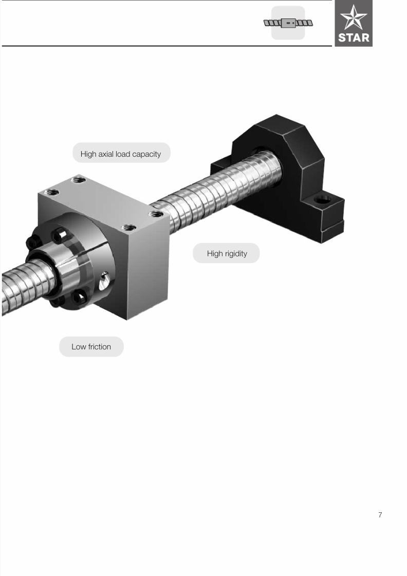
The complete linear motion drive system:
STAR Precision Ball Screw Assemblies with end bearings
and housings.
STAR Precision Ball Screw Assemblies are available with fixed
and floating bearings.
STAR also offers robust pillow block units designed for all types
of applications.
- Easy installation due to the variety of fixture options and
reference edges
- Use of premachined pin holes provides increased mounting
accuracy
Housings for various flanged nuts complete the ready-to-mount
STAR product range.
Available from stock
Low maintenance
Reference edge
7/22/2019 Tornillo de Bolas BP-120
http://slidepdf.com/reader/full/tornillo-de-bolas-bp-120 7/68 7
High axial load capacity
Low friction
High rigidity

7/22/2019 Tornillo de Bolas BP-120
http://slidepdf.com/reader/full/tornillo-de-bolas-bp-120 8/688
STAR – Precision Ball Screw Assemblies
Product Overview
Adjustable-preload single
nut DIN 69051, Part 5
SEM-E-C
Adjustable-preload
single nut SEM-E-S
Single nut with flange
FEM-E-S
Single nut with flange
DIN 69051, Part 5
FEM-E-C
Cylindrical single nut
ZEM-E-S, ZEM-E-A
Double nut with flange
FDM-E-S
Double nut with flange
DIN 69051, Part 5FDM-E-C
PageNuts for precision-rolled and
ground-thread screws
Lead P2.5 5 10 16 20 25 32 40
Diam
eterd
0
8
12
16
20
25
32
40
50
63
80
100
125
8
12
16
20
25
32
40
50
63
80
100
125
Lead P2.5 5 10 16 20 25 32 40
Other versions available upon request to suit special requirements
(e.g. other standards).
Other versions available upon request to suit special requirements
(e.g. other standards).
30
32
34
36
38
40
42
Diameterd 0

7/22/2019 Tornillo de Bolas BP-120
http://slidepdf.com/reader/full/tornillo-de-bolas-bp-120 9/68 9
End machining details
Precision-rolled screw
(available from stock)
PagePrecision Screws
3500 5600 7500
12x5
16x5, 10, 16
20x5, 20
25x5, 10, 25
32x5, 10, 20, 32
40x5, 10, 20, 40
50x5, 10, 20, 40
63x10, 20, 40
80x10, 20
8x2.5
1500 2500
1800
16x5
20x5
25x5, 10
32x5, 10
40x5, 10
50x5, 10, 20
63x10, 20
80x10, 20
1000 5000 6000 8000
100x10, 20
125x10, 20
12001500 3000
d0 x P
d0 x P
Maximum length in mm
Maximum length in mm
available upon request
standard, available from stock
available upon request
standard, available from stock
d0
8
12
16
20
25
32
40
P2.5 5 10 16 20 25 32 40
Ground-thread screws
(made to order)
14
14
46
Tolerance grades T5, T7, T9,
(P5)
Acceptance conditions
Tolerance grades T1, T3, T5
P1, P3, P5
Acceptance conditions
44
7/22/2019 Tornillo de Bolas BP-120
http://slidepdf.com/reader/full/tornillo-de-bolas-bp-120 10/6810
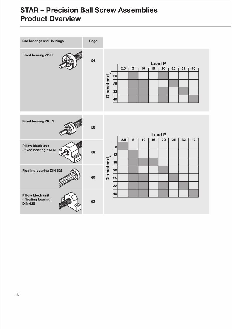
Fixed bearing ZKLN
Floating bearing DIN 625
Pillow block unit
- fixed bearing ZKLN
Fixed bearing ZKLF
PageEnd bearings and Housings
8
12
16
20
25
32
40
54
56
58
60
62
STAR – Precision Ball Screw Assemblies
Product Overview
Lead P2.5 5 10 16 20 25 32 40
Diam
eterd
0
Lead P2.5 5 10 16 20 25 32 40
20
25
32
40Diameterd
0
Pillow block unit
- floating bearing
DIN 625
7/22/2019 Tornillo de Bolas BP-120
http://slidepdf.com/reader/full/tornillo-de-bolas-bp-120 11/68 11
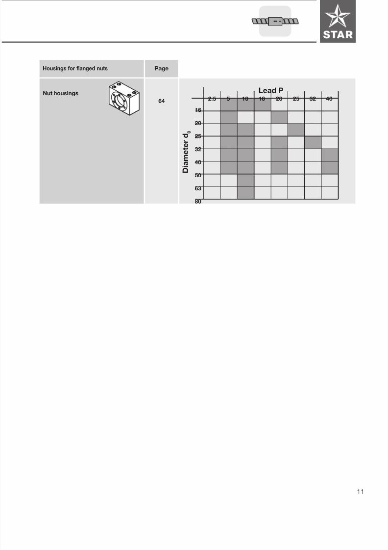
PageHousings for flanged nuts
Nut housings
64
Diameterd
0
16
20
25
32
40
50
63
80
Lead P2.5 5 10 16 20 25 32 40

7/22/2019 Tornillo de Bolas BP-120
http://slidepdf.com/reader/full/tornillo-de-bolas-bp-120 12/6812
100
90
80
70
60
50
40
30
20
10
1 2 3 987654
µ = 0. 3
µ = 0. 2
µ = 0. 0 1
0
0
µ = 0. 0 0 5
Due to their high mechanical
efficiency, ball screws in principle
are not self-locking and can
backdrive.
• The mechanical efficiency of an Acme
screw drive is a maximum of 50%,
whereas a ball screw can reach a
mechanical efficiency of up to 98%
• higher life expectancy due to
negligible wear during operation
• less drive power required
• no stick-slip effect
• more precise positioning
• higher travel speed
• less heat-up
Advantages over the
Acme screw drive
DIN 69 051 Part 1 defines
a ball screw as follows:
An assembly comprising a ball screw
shaft and ball nut, which is capable of
converting rotary motion to linear motion
and vice versa. The rolling elements of
the assembly are balls.
Lead angle (° )
Efficiency(%)
Acme screw
Ball screw
STAR – Precision Ball Screw Assemblies
General
7/22/2019 Tornillo de Bolas BP-120
http://slidepdf.com/reader/full/tornillo-de-bolas-bp-120 13/68 13
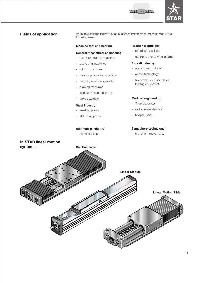
Machine tool engineering
General mechanical engineering
- paper-processing machines
- packaging machines
- printing machines
- plastics processing machines
- handling machines (robots)
- drawing machines
- lifting units (e.g. car jacks)
- valve actuators
Steel industry
- smelting plants
- slab lifting plants
Automobile industry
- steering gears
Ball screw assemblies have been successfully implemented worldwide in the
following areas:Fields of application
In STAR linear motion
systemsBall Rail Table
Linear Motion Slide
Linear Module
Reactor technology
- refueling machines
- control rod drive mechanisms
Aircraft industry
- aircraft landing flaps
- airport technology
- telescopic hoist spindles for
loading equipment
Medical engineering- X-ray apparatus
- radiotherapy devices
- hospital beds
Semaphore technology
- signal arm movements
7/22/2019 Tornillo de Bolas BP-120
http://slidepdf.com/reader/full/tornillo-de-bolas-bp-120 14/6814
l 1
l u l el e
e p
e p
ν 3 0 0 p
300
- 0
∆ l
ν u p
ν u p
2πrad
2 π
p
ν
l 0
c
+
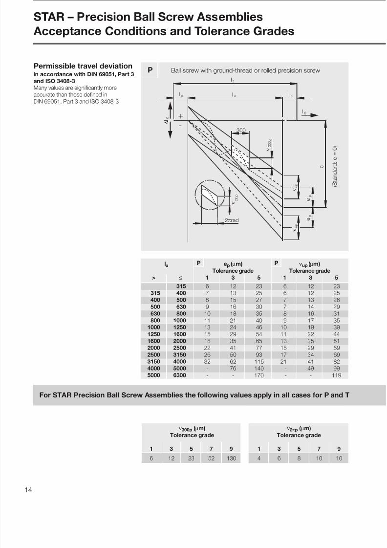
lu ep ( µm) νup ( µm)
Tolerance grade Tolerance grade
> ≤ 1 3 5 1 3 5
315 6 12 23 6 12 23315 400 7 13 25 6 12 25
400 500 8 15 27 7 13 26
500 630 9 16 30 7 14 29
630 800 10 18 35 8 16 31
800 1000 11 21 40 9 17 35
1000 1250 13 24 46 10 19 39
1250 1600 15 29 54 11 22 44
1600 2000 18 35 65 13 25 51
2000 2500 22 41 77 15 29 59
2500 3150 26 50 93 17 34 69
3150 4000 32 62 115 21 41 82
4000 5000 - 76 140 - 49 99
5000 6300 - - 170 - - 119
(Standard:c
=
0)
For STAR Precision Ball Screw Assemblies the following values apply in all cases for P and T
ν300p ( µm)
Tolerance grade
1 3 5 7 9
6 12 23 52 130
ν2πp ( µm)
Tolerance grade
1 3 5 7 9
4 6 8 10 10
P Ball screw with ground-thread or rolled precision screw
STAR – Precision Ball Screw Assemblies
Acceptance Conditions and Tolerance Grades
Permissible travel deviationin accordance with DIN 69051, Part 3
and ISO 3408-3
Many values are significantly more
accurate than those defined inDIN 69051, Part 3 and ISO 3408-3
P P

7/22/2019 Tornillo de Bolas BP-120
http://slidepdf.com/reader/full/tornillo-de-bolas-bp-120 15/68 15
l 1
l ule
e ´ p
e ´ p
ν 3 0 0 p
300
+
-
0
∆ l
l e
l 0
c = 0
T Ball screw with ground-thread or rolled precision screw
Star supplies T-type ball screws
with more accurate values than
those defined in DIN 69051 Part 3
and ISO 3408-3 (tolerance reduced
by half).
e´ ( µm)Tolerance grade
1 3 5 7 9
T
ν
Min. no. of measurements fortolerance grades
ν2πp = permissible travel variation
within 1 revolution
ν300p = permissible travel deviation
within 300 mm travel
νup = permissible travel variation
within useful travel lu
e´ = tolerance for actual mean
travel deviation
le = excess travel
lu = useful travel
∆l0 = travel deviation
l1 = thread length
l0 = nominal travel
Subindices:
0 = nominal
p = permissible
a = actual
c = travel compensation for useful
travel, defined by user
(standard: c = 0)
Symbol definitions
(excerpt):
Excesstravel
Lead
P
1 3 5 7 9 (mm)
2.5 30 20 10 5 5 10
5 15 10 6 3 3 20
10 10 5 3 1 1 40
16 8 5 3 1 1 50
20 5 5 3 1 1 60
25 4 4 3 1 1 7032 3 3 2 1 1 80
40 - 2 1 1 1 100
Minimum number of measurements
within 300 mm (measuring interval)
and permissible excess travel lemax
´
p
p

7/22/2019 Tornillo de Bolas BP-120
http://slidepdf.com/reader/full/tornillo-de-bolas-bp-120 16/6816
t5p in µm for l5d0 l5 for
tolerance grade
above up to 1 3 5 7; 9
6 12 8012 25 160
25 50 315 20 25 32 40
50 100 630
100 200 1250
5
l5l
5
l
2 d0
d 0
2 d0
l 1
5l 5l
5 p
t
5 m a x
t
A A´
AA´ t5p
A A´
t5max in µm
l1 /d0 for l1 ≥ 4l5tolerance grade
above up to 1 3 5 7; 9
40 40 50 64 8040 60 60 75 96 120
60 80 100 125 160 200
80 100 160 200 256 320
Nominal Ref. t6p in µm
diameter length for
l6 ≤ l
d0 l tolerance grade
above up to 1 3 5; 7; 9
6 20 80 10 12 20
20 50 125 12 16 2550 125 200 16 20 25
125 200 315 - 25 25
Radial run-out t6 of the bearing
diameter in relation to AA´ for l6 ≤ l
Where l6 > l, then
Nominal Ref. t7p´ in µm
diameter length for l7 ≤ l
for
d0 l tolerance grade
above up to 1 3 5; 7; 9
6 20 80 5 5 6
20 50 125 5 5 6
50 125 200 6 6 7
125 200 315 - 8 12
Coaxial deviation t7´ of the journal
diameter of the ball screw shaft in
relation to the bearing diameter
for l7 ≤ l
Where l7 > l, then
Axial runout t8´ of the shaft (bearing)
face of the ball screw shaft in
relation to the bearing diameter
Nominal t8p´ in µm
diameter for
tolerance grade
d0
above up to 1 3 5; 7; 9
6 63 3 4 5
63 125 4 5 6
125 200 - 6 8
d 0
2 d0
l 6
AA´ t6p
A A´ 2 d0
d 0
l 7
Ct7p´
C
Bearing Seat
d 0F
d
C
Ct8p´
Bearing Seat
STAR – Precision Ball Screw Assemblies
Acceptance Conditions and Tolerance Grades
≤
≤
Run-outs and location
deviationsbased on DIN 69051, Part 3 and
ISO 3408-3
Radial run-out t5 of the outer dia-
meter of the ball screw shaft over
the length l5 used to determine the
straightness in relation to AA´
Bearing Seat

7/22/2019 Tornillo de Bolas BP-120
http://slidepdf.com/reader/full/tornillo-de-bolas-bp-120 17/68 17
Axial runout t9 of the ball nut
location face in relation to A and A´
(for preloaded ball nuts only)
Radial runout t10
of the outer dia-
meter D1 of the ball nut in relation
to A and A´ (for preloaded and
rotating ball nuts only)
(fix screw against rotation)
Flange t9p in µm
diameter for
tolerance grade
D2
above up to 1 3 5; 7; 916 32 10 12 16
32 63 12 16 20
63 125 16 20 25
125 250 20 25 32
250 500 - 32 40
Outer t10p in µm
diameter for
tolerance grade
D1
über bis 1 3 5; 7; 9
16 32 10 12 1632 63 12 16 20
63 125 16 20 25
125 250 20 25 32
250 500 - 32 40
for lu /d0 ≤ 60 and
lu ≤ 4000 mm
Tpr0 ∆Tprp in % of Tpr0
(Nm) for
tolerance grade
above up to 1 3 5 7; 9
0.2 0.4 40 50 60 -
0.4 0.6 33 40 45 -0.6 1.0 30 35 40 45
1.0 2.5 25 30 35 40
2.5 6.3 20 25 30 35
6.3 10.0 - 20 25 35
for lu /d0 ≤ 40 and
lu ≤ 4000 mm
Tpr0 ∆Tprp in % of Tpr0
(Nm) for
tolerance grade
above up to 1 3 5 7; 9
0.2 0.4 35 40 50 -0.4 0.6 25 40 40 -
0.6 1.0 25 30 35 40
1.0 2.5 20 25 30 35
2.5 6.3 15 20 25 30
6.3 10.0 - 15 20 30
Permissible deviation ∆Tprp
for the
dynamic preload drag torque Tpr0
(for preloaded ball nuts only).
r
F; Ft
Force sensor
without seals T pr = F • r
with seals T t = Ft • r
p r 0
T
p r a
T
ul - L ul - L
p r p
∆ T
∆ T
p r a
±
∆ T
n n
Travel
p r p
dynamicpreloa
ded
dragtorque
lu - Ln = useful travel minus length
of ball nut
2 d0
F 0 d
2
D
2 d0
AA´ t9p
A A´
2 d0
0 d
1
D
2 d0
AA´ t10p
A A´
for lu /d0 > 60 or
lu > 4000 mm
Tpr0 ∆Tprp in % of Tpr0
(Nm) for
tolerance grade
above up to 1 3 5 7; 9
0.6 not yet determined
0.6 1.0 - 40 45 50
1.0 2.5 - 35 40 452.5 6.3 - 30 35 40
6.3 10.0 - 25 30 35
fixed

7/22/2019 Tornillo de Bolas BP-120
http://slidepdf.com/reader/full/tornillo-de-bolas-bp-120 18/6818
STAR – Precision Ball Screw Assemblies
Design Notes
Selection Criteria The following factors should be con-
sidered in the selection of the ball screw
required for a given application:
- degree of accuracy required
(lead deviation)- permissible clearance or desired
preload
- in-service load conditions
- service life
- critical speed
- buckl ing load
- rigidity
The following points should be taken
into consideration when selecting a ball
screw assembly that is to be both cost-
efficient and optimally designed:• the lead is a decisive factor for the
load-carrying capacity (depending
on the maximum possible ball dia-
meter) and the drive moment;
• the calculation of the service life
should be based on average loads
and average speeds, not on maxi-
mum values;
• in order for us to provide you with a
customized solution, installation
drawings or sketches of the nut and
screw environment should be
enclosed with your inquiry;
• no special bearings are required for
ball screws; bearings used for con-
ventional screws are suitable. At least
one bearing must be able to take up
axial thrust forces. Where high rigidity
is required, we recommend the use
of combined radial and thrust
bearings;
• the end machining will be done
according to customer specifications.
The diameter of the bearing seats
should correspond to the recom-
mended dimensions for end bearings.
A drawing should be enclosed withthe inquiry. Star standard end machi-
ning options with the matching
bearings are also available.
• radial and eccentric forces relative to
the screw must be avoided as they
have a negative effect on the life and
proper function of the ball screw.
In order to help us find the ball screw
that best suits your application, please
complete the inquiry/order form at the
back of this catalog.
Please mark any questions that you are
unable to answer as well as those
values that you would like us to define.
Inquiry / Order Form
S a m p
l e
STAR ScrewNominal diameter .......................................................... d
0=__________ mm
Lead right-hand left-hand ................................. P =__________ mm
STAR Nut
FEM-E-C ZEM-E-A
FEM-E-S ZEM-E-S
with with
backlash preload
SEM-E-C FDM-E-C
SEM-E-S FDM-E-S
Part number 1 5 - -
Mounting direction of nut:
Mounting Ø D1 (or in the case of ZEM-E-A/S, lube port) facing drive end
facing non-drive end
STAR Screw Tolerance grade P1 T1 = ν
300p= 6µm
(see Page 14/15) P3 T3 = ν300p
= 12µm
P5 T5 = ν300p
= 23µm
T7 = ν300p
= 52µm
T9 = ν300p
= 130µm
^
^
^
^
^
Total length ..................................................................... L =_______ mm
Threaded length .............................................................. L1
=_______ mm
Machining of screw ends ..................... ends not machined
(Read bearing ends annealed LG1
/ LG2
_____ / _____ mm
recommendations careful ly! ) to customer specs(drawing required)to STAR specs (page 46/47)
Type of drive end.................................. for fixed bearing for floating bearing Type of non-drive end........................... for fixed bearing for floating bearing
STAR End bearings ............. Part no./Drive end 1 5 9 - -
............ Part no./Non-drive end 1 5 9 - -
STAR Housing for flanged nut ............ Part no. 1 5 0 6 - -
7/22/2019 Tornillo de Bolas BP-120
http://slidepdf.com/reader/full/tornillo-de-bolas-bp-120 19/68 19
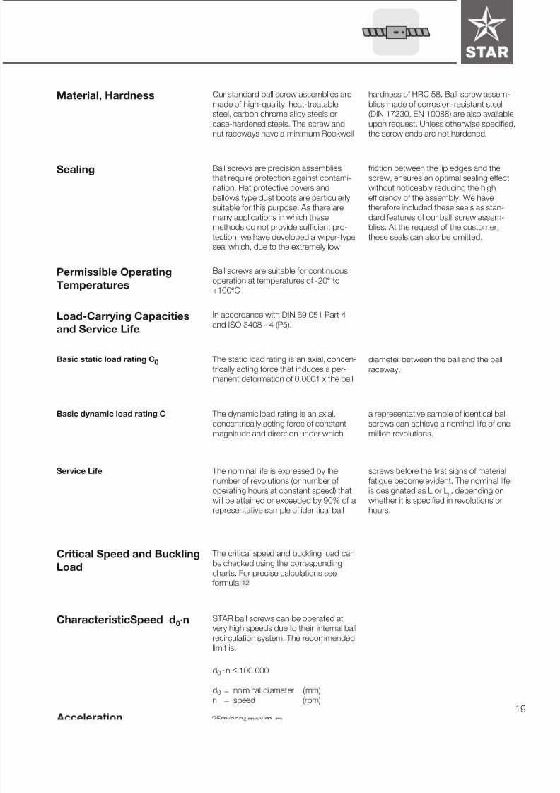
d0 • n ≤ 100 000
Permissible Operating
Temperatures
hardness of HRC 58. Ball screw assem-
blies made of corrosion-resistant steel
(DIN 17230, EN 10088) are also available
upon request. Unless otherwise specified,
the screw ends are not hardened.
Our standard ball screw assemblies are
made of high-quality, heat-treatable
steel, carbon chrome alloy steels or
case-hardened steels. The screw and
nut raceways have a minimum Rockwell
Material, Hardness
Sealing Ball screws are precision assemblies
that require protection against contami-
nation. Flat protective covers and
bellows type dust boots are particularly
suitable for this purpose. As there are
many applications in which these
methods do not provide sufficient pro-
tection, we have developed a wiper-type
seal which, due to the extremely low
friction between the lip edges and the
screw, ensures an optimal sealing effect
without noticeably reducing the high
efficiency of the assembly. We have
therefore included these seals as stan-
dard features of our ball screw assem-
blies. At the request of the customer,
these seals can also be omitted.
Ball screws are suitable for continuous
operation at temperatures of -20° to+100°C
Load-Carrying Capacities
and Service Life
In accordance with DIN 69 051 Part 4
and ISO 3408 - 4 (P5).
Basic static load rating C0 The static load rating is an axial, concen-
trically acting force that induces a per-
manent deformation of 0.0001 x the ball
Basic dynamic load rating C The dynamic load rating is an axial,concentrically acting force of constant
magnitude and direction under which
a representative sample of identical ballscrews can achieve a nominal life of one
million revolutions.
Service Life The nominal life is expressed by the
number of revolutions (or number of
operating hours at constant speed) that
will be attained or exceeded by 90% of a
representative sample of identical ball
screws before the first signs of material
fatigue become evident. The nominal life
is designated as L or Lh, depending on
whether it is specified in revolutions or
hours.
Critical Speed and BucklingLoad
The critical speed and buckling load canbe checked using the corresponding
charts. For precise calculations see
formula
CharacteristicSpeed d0·n STAR ball screws can be operated at
very high speeds due to their internal ball
recirculation system. The recommended
limit is:
d0
= nominal diameter (mm)
n = speed (rpm)
2
diameter between the ball and the ball
raceway.
12
7/22/2019 Tornillo de Bolas BP-120
http://slidepdf.com/reader/full/tornillo-de-bolas-bp-120 20/6820
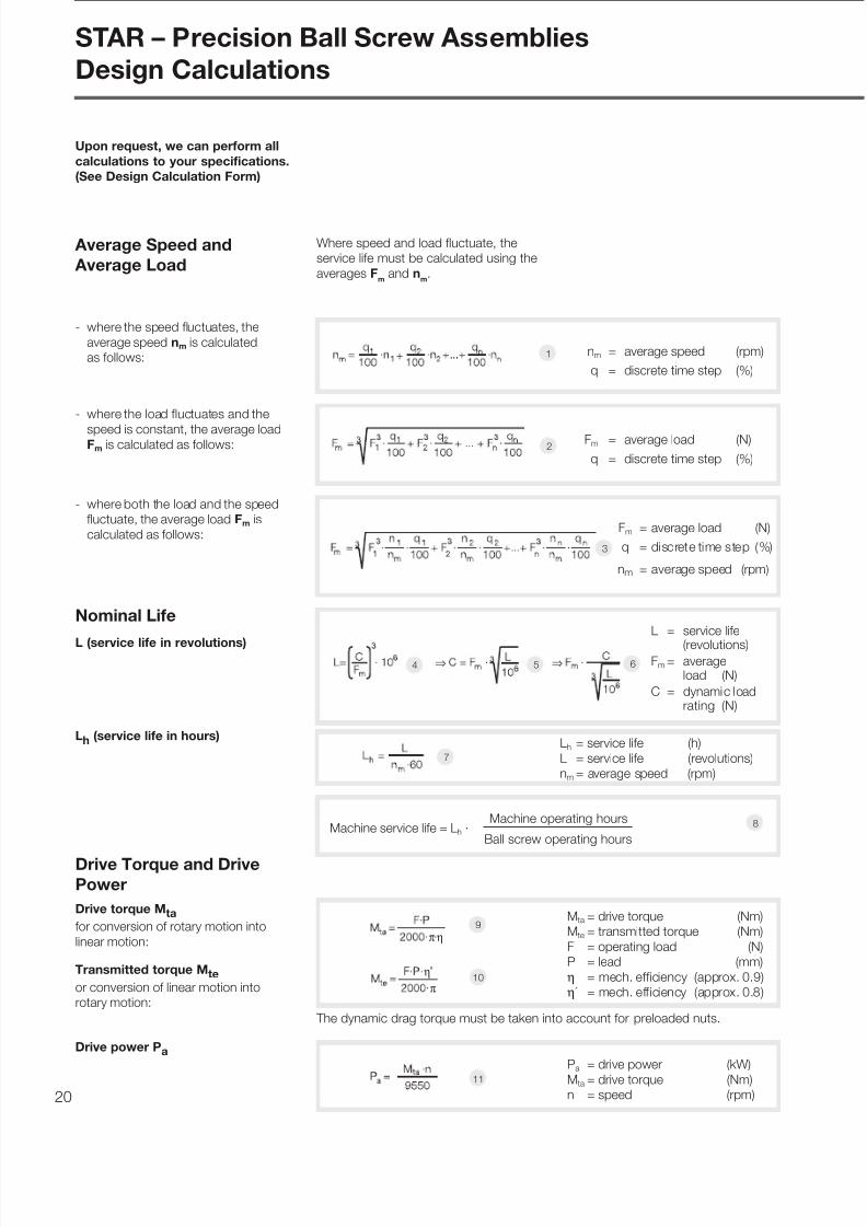
Where speed and load fluctuate, the
service life must be calculated using the
averages Fm and n
m.
- where the speed fluctuates, the
average speed nm is calculated
as follows:
Drive Torque and DrivePower
Drive torque Mta
for conversion of rotary motion into
linear motion:
Transmitted torque Mte
or conversion of linear motion into
rotary motion:
Nominal Life
L (service life in revolutions)
- where both the load and the speed
fluctuate, the average load Fm is
calculated as follows:
- where the load fluctuates and the
speed is constant, the average loadFm is calculated as follows: Fm = average load (N)
q = discrete time step (%)2
4 5 6
7
8
9
11
1 nm = average speed (rpm)
q = discrete time step (%)
Fm = average load (N)
q = discrete time step (%)
nm = average speed (rpm )
L = service life
(revolutions)Fm = average
load (N)
C = dynamic loadrating (N)
Mta = drive torque (Nm)
Mte = transmitted torque (Nm)
F = operating load (N)
P = lead (mm)
η = mech. efficiency (approx. 0.9)
η´ = mech. efficiency (approx. 0.8)
Pa = drive power (kW)
Mta = drive torque (Nm)n = speed (rpm)
Lh = service life (h)
L = service life (revolutions)
nm = average speed (rpm)
Average Speed and
Average Load
10
Lh (service life in hours)
3
+
⇒ ⇒
Machine service life = Lh ·
π η
η
π
Drive power Pa
The dynamic drag torque must be taken into account for preloaded nuts.
Upon request, we can perform all
calculations to your specifications.
(See Design Calculation Form)
STAR – Precision Ball Screw Assemblies
Design Calculations
Machine operating hours
Ball screw operating hours

7/22/2019 Tornillo de Bolas BP-120
http://slidepdf.com/reader/full/tornillo-de-bolas-bp-120 21/68 21
F1 = 50 000 N at n1 = 10 rpm for q1 = 6% of the duty cycle
F2 = 25 000 N at n2 = 30 rpm for q2 = 22% of the duty cycleF3 = 8 000 N at n3 = 100 rpm for q3 = 47% of the duty cycle
F4 = 2 000 N at n4 = 1 000 rpm for q4 = 25% of the duty cycle
100%
The service life of the machine should be 40,000 operating hours with the ball
screw operating 60% of the time.
Average speed nm
Average load Fm for variable loadand variable speed
Calculation procedure
Basic dynamic load rating C
Required service life L
(revolutions)
1
3
Calculation Example
Service life
Operating conditions
Proposed ball screw: 63 x 10
Result and selection The ball screw can now be selected from the Dimension Tables:
e.g. ball screw, size 63 x 10 R x 6-6, with preloaded single nut with flange,basic dynamic load rating C = 88 800 N, part no. 1512-6-4003.
The life of the selected ball screw
assembly is thus greater than the
required service life of 24,000 hours
(including operating hours). A smaller
ball screw could therefore be selected.
Life Lh in hours
4
7
Cross check
Life L of the selected ball screw in
revolutions
5
≈
L ≈ 1042 · 106 revolutions
+
rpm
The life L can be calculated by transposing the formulas and as follows:7 8
≈ hours
Lh = Machine operating hours ·
L = Lh · nm · 60
Ball screw operating hours
Machine operating hours
Lh = 40 000 · 60 = 24 000h
L = 24 000 · 304 · 60
L = 437 760 000 revolutions
100

7/22/2019 Tornillo de Bolas BP-120
http://slidepdf.com/reader/full/tornillo-de-bolas-bp-120 22/6822
The critical speed depends on the dia-
meter of the screw, the type of end fixity
and the free length ln. No allowance may
be made for guidance by a nut without
preload. The operating speed should
not reach more than 80% of the critical
speed. The characteristic speed is to
be taken into account: (see Page 19)
Critical Speed
Example:
The maximum operating speed in our
calculation example of n4 = 1000 rpm
is therefore below the permissible
operating speed.
0.2 0.3 0.4 0.5 0.6 0.8 1 2 3 4 5 6 7 8 9 10
20
30
40
50
60
70
80
90
100
200
300
400
500
600
800
1000
2000
3000
70
80
90
100
200
300
400
500
600
800
1000
2000
3000
100
200
300
400
500
600
800
1000
2000
3000
200
300
400
500
600
800
1000
2000
3000
8 0
6 3
5 0
4 0
3 2
8
1 2
1 6
2 0
2 5
1 0 0
1 2 5
End fixity I II III IV f nk value 27.4 18.9 12.1 4.3
Length ln (m)
lnl1
nk = critical speed (rpm)
nkper = permissible operating speed (rpm)
f nk = corrector value determined by bearing
d2 = root diameter (mm),
see Dimension Tables
ln = critical length (mm) for preloaded nut systems
l1 = threaded length (mm)
Where ln = l1 for non-preloaded nut systems
Criticalspeedn k(rpm)
fixed
fixed
fixed
floating
floating
floating
fixed
free
STAR – Precision Ball Screw Assemblies
Design Calculations
Screw diameter = 63 mm
Length ln = 2.4 m
End fixity type II (fixed - supported)
According to the graph, the critical
speed is 1850 rpm.
The permissible operating speed is thus
1850 rpm x 0.8 = 1480 rpm.
12
nkper = 0.8 · nk (rpm)13
(rpm)
7/22/2019 Tornillo de Bolas BP-120
http://slidepdf.com/reader/full/tornillo-de-bolas-bp-120 23/68 23
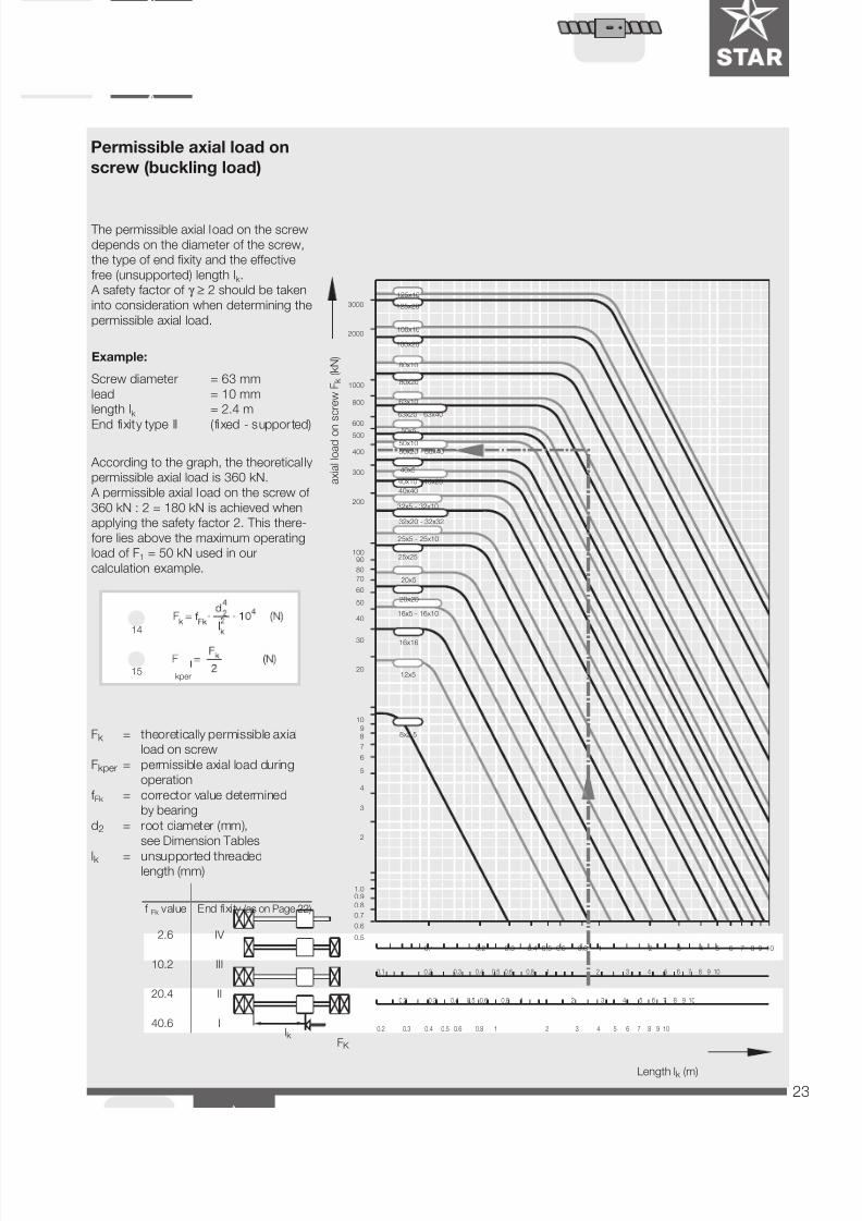
According to the graph, the theoretical ly
permissible axial load is 360 kN.
A permissible axial load on the screw of
360 kN : 2 = 180 kN is achieved when
applying the safety factor 2. This there-
fore lies above the maximum operating
load of F1 = 50 kN used in our
calculation example.
The permissible axial load on the screw
depends on the diameter of the screw,
the type of end fixity and the effective
free (unsupported) length lk .
A safety factor of γ ≥ 2 should be taken
into consideration when determining the
permissible axial load.
Example:
Screw diameter = 63 mm
lead = 10 mm
length lk = 2.4 m
End fixity type II ( fixed - supported)
Permissible axial load on
screw (buckling load)
axialloadon
screwFk
(kN)
Length lk (m)
f Fk value End fixity (as on Page 22)
2.6 IV
10.2 III
20.4 II
40.6 Ilk
Fk = theoretically permissible axial
load on screw
Fkper = permissible axial load during
operation
f Fk = corrector value determined
by bearing
d2 = root diameter (mm),
see Dimension Tables
lk = unsupported threadedlength (mm)
FK
14
0.5
0.6
0.7
0.8
0.91.0
2
3
4
5
7
89
10
6
20
30
40
50
60
70
80
90100
200
300
400
500
600
800
1000
2000
3000
0.1 0.2 0.3 0.4 0.5 0.6 0.8 1 2 3 4 5 6 7 8 9 10
0.2 0.3 0.4 0.5 0.6 0.8 2 3 4 5 6 7 8 9 10
0.2 0.3 0.4 0.5 0.6 0.8 2 3 4 5 6 7 8 9 10
8x2.5
1
1
2 3 4 5 6 7 8 9 100.4 0.5 0.6 10.2 0.30.1
16x16
12x5
16x5 - 16x10
50x5
50x1050x20 - 50x40
40x5
40x40
40x10 - 40x20
32x5 - 32x10
32x20 - 32x32
25x25
25x5 - 25x10
20x5
20x20
125x10
100x10
125x20
100x20
80x10
80x20
63x10
63x20 - 63x40
0.8
15kper
7/22/2019 Tornillo de Bolas BP-120
http://slidepdf.com/reader/full/tornillo-de-bolas-bp-120 24/6824
Nut System Preload
The rigidity of these three types of STAR nut systems is approximately the same, as the adjustable-preload
single nut and the preloaded single nut have a much more compact design, and are thus only half as long asa double-nut system (please also note the information given under “Overall Rigidity”).
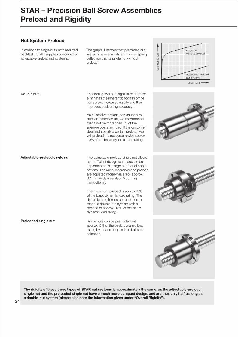
Double nut Tensioning two nuts against each other
eliminates the inherent backlash of the
ball screw, increases rigidity and thus
improves positioning accuracy.
As excessive preload can cause a re-
duction in service life, we recommendthat it not be more than 1 / 3 of the
average operating load. If the customer
does not specify a certain preload, we
will preload the nut system with approx.
10% of the basic dynamic load rating.
Adjustable-preload single nut
Preloaded single nut Single nuts can be preloaded with
approx. 5% of the basic dynamic load
rating by means of optimized ball size
selection.
The adjustable-preload single nut allows
cost-efficient design techniques to be
implemented in a large number of appli-
cations. The radial clearance and preload
are adjusted radially via a slot approx.
0.1 mm wide (see also: MountingInstructions).
The maximum preload is approx. 5%
of the basic dynamic load rating. The
dynamic drag torque corresponds to
that of a double-nut system with a
preload of approx. 13% of the basic
dynamic load rating.
single nut
without preload
Adjustable-preload
nut systems
Axial load
Axialdeflec
tion
STAR – Precision Ball Screw Assemblies
Preload and Rigidity
In addition to single nuts with reduced
backlash, STAR supplies preloaded or
adjustable-preload nut systems.
The graph illustrates that preloaded nut
systems have a significantly lower spring
deflection than a single nut withoutpreload.

7/22/2019 Tornillo de Bolas BP-120
http://slidepdf.com/reader/full/tornillo-de-bolas-bp-120 25/68 25
The rigidity of a ball screw is also influenced
by all adjoining parts such as bearings,
housing bores, nut housings etc.
Overall axial rigidity Rtot of the
ball screw
The overall axial rigidity is comprised of
the component rigidity of the bearingRaL, the screw RS and the nut unit Rnu
and is calculated according to the
following formula:
Overall Rigidity
The rigidity of the bearings corresponds
to the values found in the bearing
manufacturer’s catalog. The rigidity of
our bearing assemblies can be found
in the tables.
Rigidity of the bearing RaL
Rigidity of the screw RS
Rigidity in the area of the
nut unit Rnu
and thus equals:
lS
lS2
The lowest screw rigidity occurs at the
center of the screw ( lS2 = lS /2 ),
The rigidity of the screw depends on the
type of bearing used.
See Dimension Tables for rigidity values.
lS1
18
1. Ball screw shaft is fixed at one end.
≤19µ
Please note that in most cases therigidity RS of the screw will be signifi-
cantly lower than the rigidity Rnu of
the nut unit. In an assembly with a
diameter of 40 x 10, for example, the
rigidity Rnu of the nut unit is 2 to 3
times higher than the rigidity RS of a
screw with a length of 500 mm.
R = axial rigidity (N/ µm)
RaL= see Dimension Tables /
End Bearings and Housings
lS = distance between bearing
and bearing
lS2 = distance between bearing
and nut
2. Ball screw shaft is fixed at both ends.
d 0
D w
lS1 = distance between bearing
and nut
d0 = nominal diameter (mm)
DW = ball diameter (mm)
16
The rigidity in the area of the nut unit is
calculated according to DIN 69051 (P1).See Dimension Tables for rigidity values.
µ
17µ

7/22/2019 Tornillo de Bolas BP-120
http://slidepdf.com/reader/full/tornillo-de-bolas-bp-120 26/6826
- adjustable-preload single nut
- double nut
Nut Mounting
STAR – Precision Ball Screw Assemblies
Mounting and Lubrication Instructions
These models are supplied with pre-
mounted nut units. The nut unit and
screw may not be disassembled.
Please consult us first, should this be-
come necessary for any reason.
The nut unit may only be mounted using
a mounting arbor. The outer diameter of
the arbor should be approx. 0.1 mm
smaller than the root diameter of the
screw. In most cases, the transport
arbor on which the nuts are delivered
may be used to mount the nut. The end
of the screw thread must be chamfered
in order to prevent damage to the seal
and the internal components of the nut
unit.
The nut is to be mounted as follows:
Remove the rubber ring from one end of
the mounting arbor.
Push the mounting arbor with nut until it
engages with the end of the thread.
The arbor must make contact without
axial clearance.
Carefully turn the nut unit onto the
thread, applying only light axialpressure.
Do not remove the mounting arbor until
the entire nut unit is seated on the
screw thread.
Proceed in the reverse order when
removing the nut from the screw. Take
particular care not to damage the nut,
screw or internal components, as this
could result in the premature failure of
the ball screw assembly.
Mounting instructions are supplied as
standard alon with ever unit.
- single nut with reduced backlash
- adjustable preload single nut
7/22/2019 Tornillo de Bolas BP-120
http://slidepdf.com/reader/full/tornillo-de-bolas-bp-120 27/68 27
F=T /r
r
pr0
D 1
F
Adjusting
bolt
Measuring gauge
e.g. spring gauge
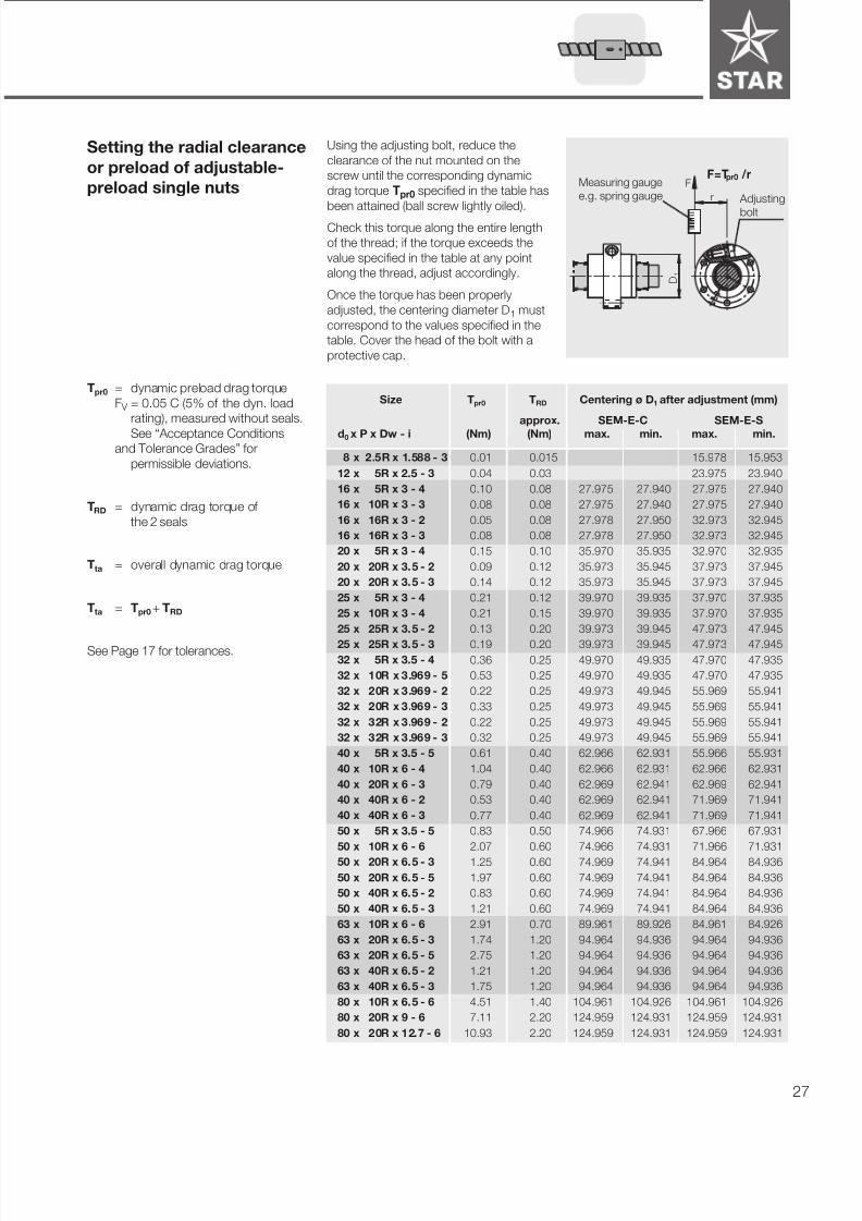
Setting the radial clearance
or preload of adjustable-
preload single nuts
Using the adjusting bolt, reduce the
clearance of the nut mounted on the
screw until the corresponding dynamic
drag torque Tpr0 specified in the table has
been attained (ball screw lightly oiled).
Check this torque along the entire length
of the thread; if the torque exceeds the
value specified in the table at any point
along the thread, adjust accordingly.
Once the torque has been properly
adjusted, the centering diameter D1 must
correspond to the values specified in the
table. Cover the head of the bolt with a
protective cap.
Tpr0 = dynamic preload drag torque
F V = 0.05 C (5% of the dyn. load
rating), measured without seals.
See “Acceptance Conditions
and Tolerance Grades” for
permissible deviations.
TRD = dynamic drag torque of
the 2 seals
Tta = overall dynamic drag torque
Tta = Tpr0 + TRD
See Page 17 for tolerances.
Size Tpr0 TRD Centering ø D1 after adjustment (mm)
approx. SEM-E-C SEM-E-S
d0 x P x Dw - i (Nm) (Nm) max. min. max. min.
8 x 2.5R x 1.588 - 3 0.01 0.015 15.978 15.953
12 x 5R x 2.5 - 3 0.04 0.03 23.975 23.940
16 x 5R x 3 - 4 0.10 0.08 27.975 27.940 27.975 27.940
16 x 10R x 3 - 3 0.08 0.08 27.975 27.940 27.975 27.940
16 x 16R x 3 - 2 0.05 0.08 27.978 27.950 32.973 32.945
16 x 16R x 3 - 3 0.08 0.08 27.978 27.950 32.973 32.945
20 x 5R x 3 - 4 0.15 0.10 35.970 35.935 32.970 32.935
20 x 20R x 3.5 - 2 0.09 0.12 35.973 35.945 37.973 37.945
20 x 20R x 3.5 - 3 0.14 0.12 35.973 35.945 37.973 37.945
25 x 5R x 3 - 4 0.21 0.12 39.970 39.935 37.970 37.935
25 x 10R x 3 - 4 0.21 0.15 39.970 39.935 37.970 37.935
25 x 25R x 3.5 - 2 0.13 0.20 39.973 39.945 47.973 47.945
25 x 25R x 3.5 - 3 0.19 0.20 39.973 39.945 47.973 47.945
32 x 5R x 3.5 - 4 0.36 0.25 49.970 49.935 47.970 47.935
32 x 10R x 3.969 - 5 0.53 0.25 49.970 49.935 47.970 47.935
32 x 20R x 3.969 - 2 0.22 0.25 49.973 49.945 55.969 55.941
32 x 20R x 3.969 - 3 0.33 0.25 49.973 49.945 55.969 55.941
32 x 32R x 3.969 - 2 0.22 0.25 49.973 49.945 55.969 55.941
32 x 32R x 3.969 - 3 0.32 0.25 49.973 49.945 55.969 55.941
40 x 5R x 3.5 - 5 0.61 0.40 62.966 62.931 55.966 55.931
40 x 10R x 6 - 4 1.04 0.40 62.966 62.931 62.966 62.931
40 x 20R x 6 - 3 0.79 0.40 62.969 62.941 62.969 62.941
40 x 40R x 6 - 2 0.53 0.40 62.969 62.941 71.969 71.941
40 x 40R x 6 - 3 0.77 0.40 62.969 62.941 71.969 71.941
50 x 5R x 3.5 - 5 0.83 0.50 74.966 74.931 67.966 67.931
50 x 10R x 6 - 6 2.07 0.60 74.966 74.931 71.966 71.931
50 x 20R x 6.5 - 3 1.25 0.60 74.969 74.941 84.964 84.936
50 x 20R x 6.5 - 5 1.97 0.60 74.969 74.941 84.964 84.936
50 x 40R x 6.5 - 2 0.83 0.60 74.969 74.941 84.964 84.936
50 x 40R x 6.5 - 3 1.21 0.60 74.969 74.941 84.964 84.936
63 x 10R x 6 - 6 2.91 0.70 89.961 89.926 84.961 84.926
63 x 20R x 6.5 - 3 1.74 1.20 94.964 94.936 94.964 94.936
63 x 20R x 6.5 - 5 2.75 1.20 94.964 94.936 94.964 94.936
63 x 40R x 6.5 - 2 1.21 1.20 94.964 94.936 94.964 94.936
63 x 40R x 6.5 - 3 1.75 1.20 94.964 94.936 94.964 94.936
80 x 10R x 6.5 - 6 4.51 1.40 104.961 104.926 104.961 104.926
80 x 20R x 9 - 6 7.11 2.20 124.959 124.931 124.959 124.931
80 x 20R x 12.7 - 6 10.93 2.20 124.959 124.931 124.959 124.931

7/22/2019 Tornillo de Bolas BP-120
http://slidepdf.com/reader/full/tornillo-de-bolas-bp-120 28/6828
It is not normally necessary to remove
the preservative coating before
installation.
- If the ball screw is contaminated it
must first be cleaned (see “Cleaning”)
and reoiled.
- Push the nut unit into the mounting
bore, taking care to avoid anyimpacts or misalignment.
- Tighten the mounting bolts using a
torque wrench if necessary. See table
for the tightening torque that corre-
sponds to the bolt strength class.
Bolt
diameter
(mm)
Tightening torque (Nm)
strength class
to DIN ISO 898:
8.8 10.9 12.9
M 3 1.3 1.8 2.1
M 4 2.7 3.8 4.6
M 6 9.5 13 16
M 8 23 32 39
M 10 46 64 77
M 12 80 110 135
M 16 195 275 330
Installation in the Machine
Storage Ball screw assemblies are high-quality
systems that must be treated with due
care. In order to prevent damage and
contamination, the elements should not
be removed from the protective wrapping
until immediately before installation.
Once they have been removed from the
packaging, they must be set down on
V-shaped cradles.
Tolerances Observe the correct tolerances when
installing the nut (see “Nut Housings”).
STAR – Precision Ball Screw Assemblies
Mounting and Lubrication Instructions
5 - 10 mm
Inserting the wiper-type seal Position the nut on the screw as
illustrated in the diagram. Insert the
wiper so that its projection is in the
recess and press it in until it snaps into
the groove. While turning the nut on the
screw, watch the wiper lip carefully and
straighten it if necessary by applying
pressure to the end surface. Ensure that
the lip is not damaged.
Be careful not to run the nut past the end of the screw thread.
7/22/2019 Tornillo de Bolas BP-120
http://slidepdf.com/reader/full/tornillo-de-bolas-bp-120 29/68 29
Various cleaning agents can be used to
degrease and wash the assembly:
- aqueous cleaning agents- organic cleaning agents
Do not use trichloroethylene!
Immediately after cleaning,
thoroughly dry all parts, thenapply a preservative coating
or anti-corrosion oil.
In all cases, take care to observe the
appropriate legal regulations (environ-
mental protection, health and safety at
work, etc.) as well as the specifications
for the cleaning agent (e.g. handling).
Lubrication
Before the ball screw is put into
operation, a lubricant must be
applied to the nut via the lube hole.
The standard lubrication practices that
apply to antifriction bearings also apply
to ball screws. Either oil or grease may
be used as a lubricant.
Lubricant loss is, however, greater than
that of antifriction bearings due to the
axial motion between the screw and the
nut. In most cases, the initial supply
of grease will not last for the entire
service life of the assembly. Graphite
and MoS2 additives must not be used.
The influence of the temperature on the
performance of the ball screw is very
significant, as thermal expansion inter-
feres with the positioning accuracy of
the assembly. One of the advantages of
oil lubrication is the minimized heat
build-up of the ball screw, particularly
at high speeds. As a rule, commercially
Oil lubrication
The advantage of grease lubrication is
that the ball screw can run for 500 to
1000 hours on one supply of grease.
As a result, a lubricating system is not
required in many cases.
The amount of grease used should fi ll
the pockets to approximately half of
their capacity. All commercially available
available petroleum base oils used for
antifriction bearings are suitable. The
necessary viscosity depends on the
speed, temperature and load conditions
of the respective application (see DIN
51501, 51517, 51519 and GfT Work-
sheet 3).
Grease lubrication antifriction-bearing lubricating greases
may be used. Do not mix different
varieties together. Ball screws subjected
to normal loads should be lubricated
with a KP2K antifriction bearing lubri-
cating grease as specified in DIN 51825.
Read the lubricant manufacturer specifi-
cations carefully!
Cleaning

7/22/2019 Tornillo de Bolas BP-120
http://slidepdf.com/reader/full/tornillo-de-bolas-bp-120 30/6830
Mounting dimensions
to DIN 69 051, Part 5
Flange type C
Size Part number Load ratings Rigidity Mass moment ofdyn. stat. Nut Screw inertia of screw
d0 x P x Dw - i C C0 Rnu RS1 JS
(N) (N) (N/ µm) (N/ µm/m) (kgcm2 /m)
16 x 5 R x 3-4 1502-0-1085 12300 16100 350 32 0.29
16 x 10 R x 3-3 1502-0-4065 9600 12300 280 32 0.2916 x 16 R x 3-3 1502-0-6065 9200 11900 260 32 0.2920 x 5 R x 3-4 1502-1-1065 14300 21600 440 53 0.79
20 x 20 R x 3.5-3 1502-1-7065 13300 18800 340 52 0.74
25 x 5 R x 3-4 1502-2-1065 15900 27200 510 86 2.1125 x 10 R x 3-4 1502-2-4065 15800 27000 540 86 2.3325 x 25 R x 3.5-3 1502-2-8065 14600 23200 404 84 2.04
32 x 5 R x 3.5-4 1502-3-1065 21500 40000 610 144 5.67
32 x 10 R x 3.969-5 1502-3-4086 31700 58200 834 141 6.1432 x 20 R x 3.969-3 1502-3-7065 19600 33600 500 141 6.1432 x 32 R x 3.969-3 1502-3-9065 19400 34000 500 141 5.89
40 x 5 R x 3.5-5 1502-4-1066 29100 64300 880 232 14.9040 x 10 R x 6-4 1502-4-4065 50000 86300 840 211 12.5740 x 20 R x 6-3 1502-4-7065 37800 62800 640 211 12.5740 x 40 R x 6-3 1502-4-9065 36900 62200 620 211 12.57
50 x 5 R x 3.5-5 1502-5-1066 32100 81500 1010 373 38.52
50 x 10 R x 6-6 1502-5-4066 79700 166500 1450 345 33.6650 x 20 R x 6.5-5 1502-5-7086 75700 149600 1300 340 32.15
50 x 40 R x 6.5-3 1502-5-9065 46500 85900 770 340 32.15
63 x 10 R x 6-6 1502-6-4066 88800 214200 1690 569 91.51
63 x 20 R x 6.5-5 1502-6-7086 83900 190300 1550 563 88.2863 x 40 R x 6.5-3 1502-6-9065 53300 114000 960 563 88.28
80 x 10 R x 6.5-6 1502-7-4066 108400 291700 1950 938 246.00
80 x 20 R x 12.7-6 1502-7-7066 262700 534200 2320 832 193.20
80 x 20 R x 9-6 1502-7-7086 170900 403900 2330 894 237.20100 x 10 R x 6.5-6 1502-8-4066 119500 371900 2200 1501 631.80
100 x 20 R x 12.7-6 1502-8-7066 295100 686400 2760 1366 521.90
125 x 10 R x 6.5-6 1502-9-4066 130600 468700 2390 2391 1606.00125 x 20 R x 12.7-6 1502-9-7066 326500 870400 3180 2220 1380.00
d0 = nominal diameter
P = Lead
(R = right-hand thread,
L = left-hand thread)
DW = ball diameter
i = number of ball track turns
STAR – Precision Ball Screw Assemblies
Single Nut with Flange FEM-E-C
Nut version:
with reduced backlash or preloaded by
means of optimized ball size selection

7/22/2019 Tornillo de Bolas BP-120
http://slidepdf.com/reader/full/tornillo-de-bolas-bp-120 31/68 31
9 0 °
L 4
D
L
5
D 1
L3
L 9
2 2 . 5
°
9 0 °
L 9 3
0 °
3 0 °
D7
D7
S
S
D 6
D 6
L 3/2
d0 ≤ 32
d0 ≥ 40
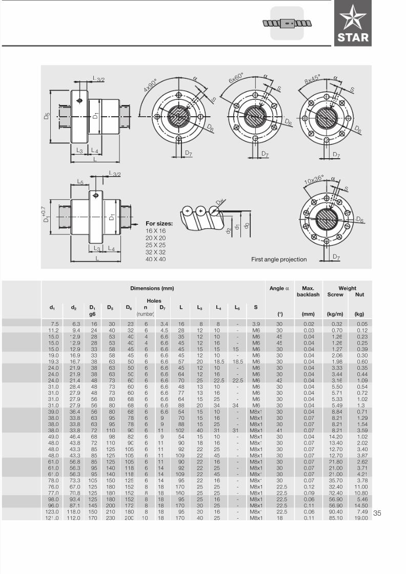
Dimensions (mm) Max. Weight
backlash Screw Nut
Holesd1 d2 D1 D5 D6 n D7 L L3 L4 L9 S
g6 (number) (mm) (kg/m) (kg)
15.0 12.9 28 48 38 6 5.5 35 12 10 44 M6 0.04 1.26 0.18
15.0 12.9 28 48 38 6 5.5 45 12 18 44 M6 0.04 1.26 0.21
15.0 12.9 28 48 38 6 5.5 61 12 20 44 M6 0.04 1.27 0.26
19.0 16.9 36 58 47 6 6.5 45 12 10 51 M6 0.04 2.06 0.33
19.3 16.7 36 58 47 6 6.5 77 12 25 51 M6 0.04 1.98 0.49
24.0 21.9 40 62 51 6 6.5 45 12 10 55 M6 0.04 3.33 0.36
24.0 21.9 40 62 51 6 6.5 64 12 16 55 M6 0.04 3.44 0.47
24.0 21.4 40 62 51 6 6.5 95 12 30 55 M6 0.04 3.16 0.63
31.0 28.4 50 80 65 6 9 48 13 10 71 M6 0.04 5.50 0.62
31.0 27.9 50 80 65 6 9 77 13 16 71 M6 0.04 5.71 0.84
31.0 27.9 50 80 65 6 9 84 13 25 71 M6 0.04 5.33 0.90
31.0 27.9 50 80 65 6 9 120 13 40 71 M6 0.04 5.49 1.21
39.0 36.4 63 93 78 8 9 54 15 10 81.5 M8x1 0.04 8.84 1.0338.0 33.8 63 93 78 8 9 70 15 16 81.5 M8x1 0.07 8.21 1.19
38.0 33.8 63 93 78 8 9 88 15 25 81.5 M8x1 0.07 8.21 1.44
38.0 33.8 63 93 78 8 9 142 15 45 81.5 M8x1 0.07 8.21 2.16
49.0 46.4 75 110 93 8 11 54 15 10 97.5 M8x1 0.04 14.20 1.39
48.0 43.8 75 110 93 8 11 90 18 16 97.5 M8x1 0.07 13.40 2.14
48.0 43.3 75 110 93 8 11 132 18 25 97.5 M8x1 0.07 12.70 2.73
48.0 43.3 75 110 93 8 11 149 18 45 97.5 M8x1 0.07 12.70 3.04
61.0 56.8 90 125 108 8 11 90 22 16 110 M8x1 0.07 21.80 2.56
61.0 56.3 95 135 115 8 13.5 132 22 25 117.5 M8x1 0.07 21.00 4.51
61.0 56.3 95 135 115 8 13.5 149 22 45 117.5 M8x1 0.07 21.00 5.04
78.0 73.3 105 145 125 8 13.5 95 22 16 127.5 M8x1 0.07 35.70 3.4
76.0 67.0 125 165 145 8 13.5 170 25 25 147.5 M8x1 0.12 32.40 10.2
77.0 70.8 125 165 145 8 13.5 160 25 25 147.5 M8x1 0.09 32.40 9.95
98.0 93.4 125 165 145 8 13.5 95 25 16 147.5 M8x1 0.06 56.90 4.4
96.0 87.1 150 202 176 8 17.5 170 30 25 178.5 M8x1 0.11 52.70 14.3
123.0 118.0 150 202 176 8 17.5 95 25 16 178.5 M8x1 0.06 90.40 5.65121.0 112.0 170 222 196 8 17.5 170 40 25 198.5 M8x1 0.11 85.10 16.1
d 0
d 1
d 2
D w
First angle projection

7/22/2019 Tornillo de Bolas BP-120
http://slidepdf.com/reader/full/tornillo-de-bolas-bp-120 32/6832
Mounting dimensions
to DIN 69 051, Part 5
Flange type C
Size Part number Load ratings Rigidity Mass moment ofdyn. stat. Nut Screw inertia of screw
d0 x P x Dw - i C C0 Rnu RS1 JS
(N) (N) (N/ µm) (N/ µm/m) (kgcm2 /m)
16 x 5 R x 3-4 1512-0-1075 12300 16100 350 32 0.29
16 x 10 R x 3-3 1512-0-4055 9600 12300 280 32 0.29
16 x 16 R x 3-3 1512-0-6055 9200 11900 260 32 0.3320 x 5 R x 3-4 1512-1-1055 14300 21600 440 53 0.7920 x 20 R x 3.5-3 1512-1-7055 13300 18800 340 52 0.74
25 x 5 R x 3-4 1512-2-1055 15900 27200 510 86 2.11
25 x 10 R x 3-4 1512-2-4055 15800 27000 540 86 2.3325 x 25 R x 3.5-3 1512-2-8055 14600 23200 404 84 2.04
32 x 5 R x 3.5-4 1512-3-1055 21500 40000 610 144 5.67
32 x 10 R x 3.969-5 1512-3-4075 31700 58200 834 141 6.14
32 x 20 R x 3.969-3 1512-3-7055 19600 33600 500 141 6.1432 x 32 R x 3.969-3 1512-3-9055 19400 34000 500 141 5.59
40 x 5 R x 3.5-5 1512-4-1055 29100 64300 880 232 14.9040 x 10 R x 6-4 1512-4-4055 50000 86300 840 211 12.57
40 x 20 R x 6-3 1512-4-7055 37800 62800 640 211 12.5740 x 40 R x 6-3 1512-4-9055 36900 62200 620 211 12.57
50 x 5 R x 3.5-5 1512-5-1055 32100 81500 1010 373 38.52
50 x 10 R x 6-6 1512-5-4055 79700 166500 1450 345 33.66
50 x 20 R x 6.5-5 1512-5-7076 75700 149600 1300 340 32.1550 x 40 R x 6.5-3 1512-5-9055 46500 85900 770 340 32.15
63 x 10 R x 6-6 1512-6-4055 88800 214200 1690 569 91.51
63 x 20 R x 6.5-5 1512-6-7076 83900 190300 1550 563 88.28
63 x 40 R x 6.5-3 1512-6-9055 53300 114000 960 563 88.2880 x 10 R x 6.5-6 1512-7-4055 108400 291700 1950 938 246.00
80 x 20 R x 9-6 1512-7-7075 170900 403900 2330 894 237.20
80 x 20 R x 12.7- 6 1512-7-7055 262700 534200 2320 832 193.20
STAR – Precision Ball Screw Assemblies
Adjustable-Preload Single Nut SEM-E-C
d0 = nominal diameter
P = Lead
(R = right-hand thread,
L = left-hand thread)
DW = ball diameter
i = number of ball track turns
7/22/2019 Tornillo de Bolas BP-120
http://slidepdf.com/reader/full/tornillo-de-bolas-bp-120 33/68 33
Dimensions (mm) Weight
Screw Nut
Holesd1 d2 D1 D5 D6 n D7 L L3 L4 L5 L6 L9 S
f9 (number) (kg/m) (kg)
15 12.9 28 48 38 6 5.5 35 15 10 10 7.1 44 M6 1.26 0.19
15 12.9 28 48 38 6 5.5 45 15 15 15 11 44 M6 1.26 0.22
15 12.9 28 48 38 6 5.5 61 15 20 23 10 44 M6 1.27 0.29
19 16.9 36 58 47 6 6.5 45 15 10 15 7.1 51 M6 2.06 0.35
19.3 16.7 36 58 47 6 6.5 77 20 25 28.5 12.5 51 M6 1.98 0.56
24 21.9 40 62 51 6 6.5 45 20 10 12.5 9.6 55 M6 3.33 0.43
24 21.9 40 62 51 6 6.5 64 20 16 22 10 55 M6 3.44 0.54
24 21.4 40 62 51 6 6.5 95 25 30 35 14 55 M6 3.16 0.77
31 28.4 50 80 65 6 9 48 20 10 14 9.5 71 M6 5.50 0.74
31 27.9 50 80 65 6 9 77 20 16 28.5 12.5 71 M6 5.71 0.97
31 27.9 50 80 65 6 9 84 20 25 32 12.5 71 M6 5.33 1.04
31 27.9 50 80 65 6 9 120 20 40 50 12.5 71 M6 5.49 1.34
39 36.4 63 93 78 8 9 54 25 10 14.5 12 81.5 M8x1 8.84 1.2538 33.8 63 93 78 8 9 70 25 16 22.5 11.8 81.5 M8x1 8.21 1.39
38 33.8 63 93 78 8 9 88 25 25 31.5 16 81.5 M8x1 8.21 1.55
38 33.8 63 93 78 8 9 142 40 45 51 25 81.5 M8x1 8.21 2.69
49 46.4 75 110 93 8 11 54 25 10 14.5 12 97.5 M8x1 14.20 1.67
48 43.8 75 110 93 8 11 90 30 16 30 14.1 97.5 M8x1 13.40 2.46
48 43.3 75 110 93 8 11 132 30 25 51 20 97.5 M8x1 12.70 3.08
48 43.3 75 110 93 8 11 149 30 45 59.5 18 97.5 M8x1 12.70 3.39
61 56.8 90 125 108 8 11 90 30 16 30 14 110 M8x1 21.80 2.83
61 56.3 95 135 115 8 13.5 132 30 25 51 20 117.5 M8x1 21.00 4.86
61 56.3 95 135 115 8 13.5 149 30 45 59.5 18 117.5 M8x1 21.00 5.36
78 73.3 105 145 125 8 13.5 95 30 16 32.5 14 127.5 M8x1 5.70 3.73
77 70.8 125 165 145 8 13.5 160 50 25 55 23.5 147.5 M8x1 32.40 10.88
76 67.0 125 165 145 8 13.5 170 50 25 60 23.7 147.5 M8x1 32.40 13.50
d0 ≤ 32
D 1 +
0 . 7
D 5
L 5
L3 L4
L
9 0 °
2 2 . 5
°
3 0 °
3 0 °
9 0 °
L 9
L 9
L 6S
D 6
1 D
D 6
S
D7
D7 d0 ≥ 40
d 0
d 1
d 2
D w
First angle projection
7/22/2019 Tornillo de Bolas BP-120
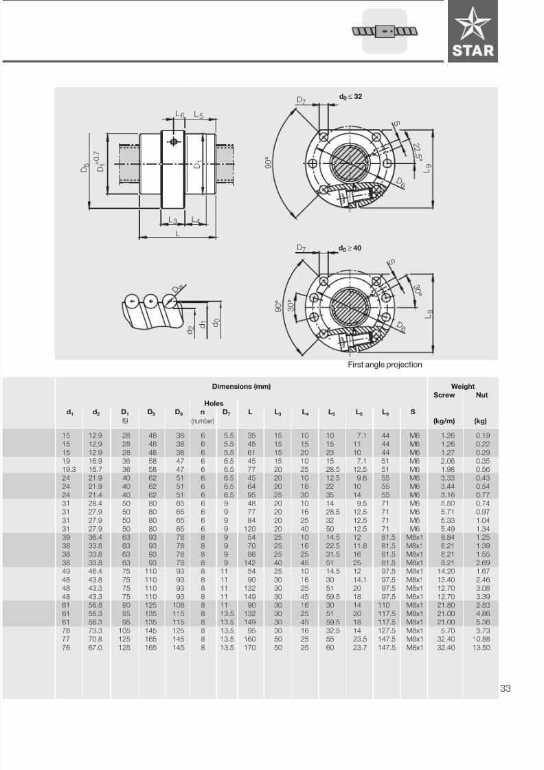
http://slidepdf.com/reader/full/tornillo-de-bolas-bp-120 34/6834
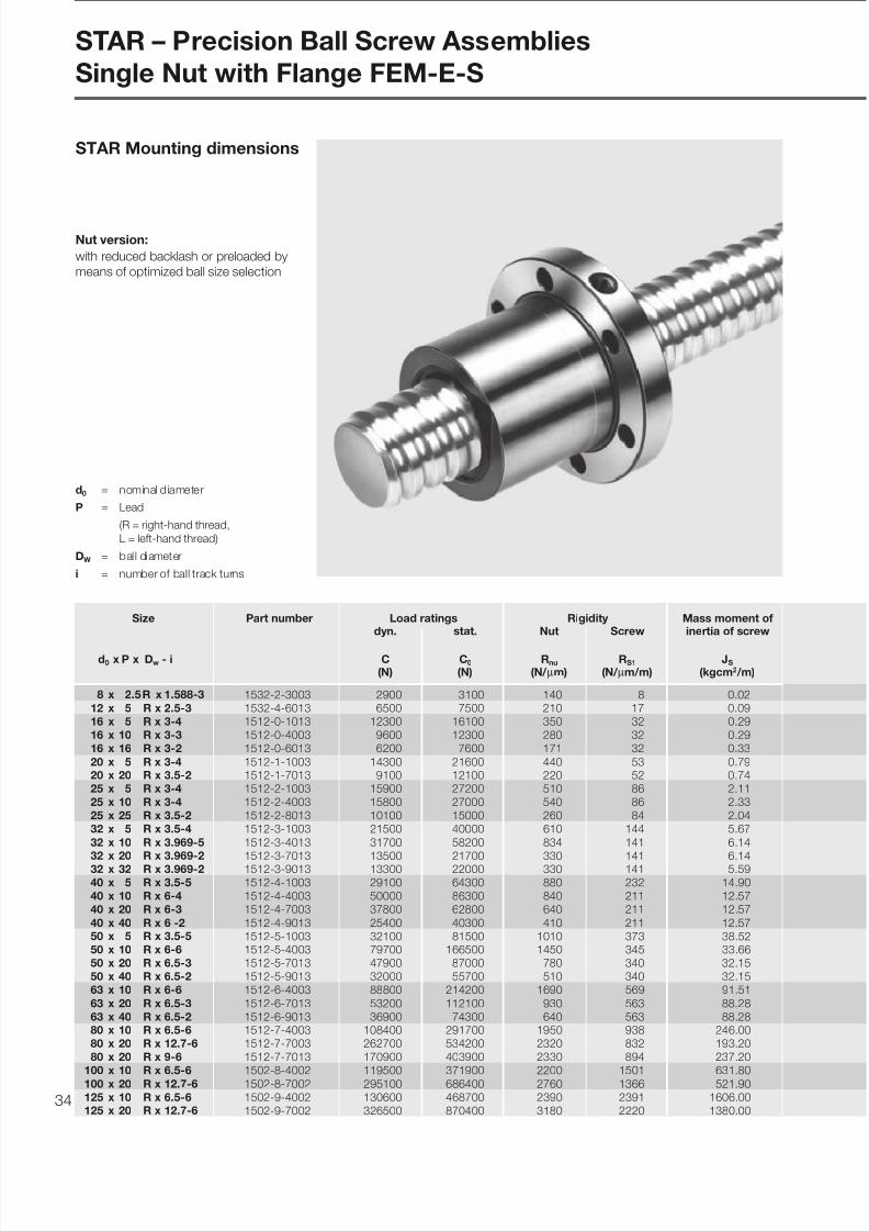
STAR – Precision Ball Screw Assemblies
Single Nut with Flange FEM-E-S
Size Part number Load ratings Rigidity Mass moment ofdyn. stat. Nut Screw inertia of screw
d0 x P x Dw - i C C0 Rnu RS1 JS
(N) (N) (N/ µm) (N/ µm/m) (kgcm2 /m)
8 x 2.5R x 1.588-3 1532-2-3003 2900 3100 140 8 0.0212 x 5 R x 2.5-3 1532-4-6013 6500 7500 210 17 0.0916 x 5 R x 3-4 1512-0-1013 12300 16100 350 32 0.2916 x 10 R x 3-3 1512-0-4003 9600 12300 280 32 0.2916 x 16 R x 3-2 1512-0-6013 6200 7600 171 32 0.33
20 x 5 R x 3-4 1512-1-1003 14300 21600 440 53 0.7920 x 20 R x 3.5-2 1512-1-7013 9100 12100 220 52 0.7425 x 5 R x 3-4 1512-2-1003 15900 27200 510 86 2.1125 x 10 R x 3-4 1512-2-4003 15800 27000 540 86 2.3325 x 25 R x 3.5-2 1512-2-8013 10100 15000 260 84 2.0432 x 5 R x 3.5-4 1512-3-1003 21500 40000 610 144 5.67
32 x 10 R x 3.969-5 1512-3-4013 31700 58200 834 141 6.1432 x 20 R x 3.969-2 1512-3-7013 13500 21700 330 141 6.1432 x 32 R x 3.969-2 1512-3-9013 13300 22000 330 141 5.5940 x 5 R x 3.5-5 1512-4-1003 29100 64300 880 232 14.9040 x 10 R x 6-4 1512-4-4003 50000 86300 840 211 12.5740 x 20 R x 6-3 1512-4-7003 37800 62800 640 211 12.57
40 x 40 R x 6 -2 1512-4-9013 25400 40300 410 211 12.5750 x 5 R x 3.5-5 1512-5-1003 32100 81500 1010 373 38.5250 x 10 R x 6-6 1512-5-4003 79700 166500 1450 345 33.6650 x 20 R x 6.5-3 1512-5-7013 47900 87000 780 340 32.1550 x 40 R x 6.5-2 1512-5-9013 32000 55700 510 340 32.1563 x 10 R x 6-6 1512-6-4003 88800 214200 1690 569 91.51
63 x 20 R x 6.5-3 1512-6-7013 53200 112100 930 563 88.2863 x 40 R x 6.5-2 1512-6-9013 36900 74300 640 563 88.2880 x 10 R x 6.5-6 1512-7-4003 108400 291700 1950 938 246.0080 x 20 R x 12.7-6 1512-7-7003 262700 534200 2320 832 193.2080 x 20 R x 9-6 1512-7-7013 170900 403900 2330 894 237.20
100 x 10 R x 6.5-6 1502-8-4002 119500 371900 2200 1501 631.80
100 x 20 R x 12.7-6 1502-8-7002 295100 686400 2760 1366 521.90125 x 10 R x 6.5-6 1502-9-4002 130600 468700 2390 2391 1606.00125 x 20 R x 12.7-6 1502-9-7002 326500 870400 3180 2220 1380.00
Nut version:
STAR Mounting dimensions
d0 = nominal diameter
P = Lead
(R = right-hand thread,
L = left-hand thread)
DW = ball diameter
i = number of ball track turns
with reduced backlash or preloaded by
means of optimized ball size selection
7/22/2019 Tornillo de Bolas BP-120
http://slidepdf.com/reader/full/tornillo-de-bolas-bp-120 35/68 35
6 x 6 0
° α
D 6
D7
S
L 4L3
L
D 5
D 1
D 1 +
0 . 7
L5
L4L3
L
D 1
4 x 9
0 ° α
S
D 6
D7
1 0 x 3 6 °
S
α
D7
D 6
8 x 4 5
° α
S
D 6
D7
L 3/2
L 3/2
Dimensions (mm) Angle α Max. Weight
backlash Screw Nut
Holesd1 d2 D1 D5 D6 n D7 L L3 L4 L5 S
g6 (number) ( ° ) (mm) (kg/m) (kg)
7.5 6.3 16 30 23 6 3.4 16 8 8 - 3.9 30 0.02 0.32 0.05
11.2 9.4 24 40 32 6 4.5 28 12 10 - M6 30 0.03 0.70 0.12
15.0 12.9 28 53 40 4 6.6 35 12 10 - M6 45 0.04 1.26 0.23
15.0 12.9 28 53 40 4 6.6 45 12 16 - M6 45 0.04 1.26 0.25
15.0 12.9 33 58 45 6 6.6 45 15 15 15 M6 30 0.04 1.27 0.3919.0 16.9 33 58 45 6 6.6 45 12 10 - M6 30 0.04 2.06 0.30
19.3 16.7 38 63 50 6 6.6 57 20 18.5 18.5 M6 30 0.04 1.98 0.60
24.0 21.9 38 63 50 6 6.6 45 12 10 - M6 30 0.04 3.33 0.35
24.0 21.9 38 63 50 6 6.6 64 12 16 - M6 30 0.04 3.44 0.44
24.0 21.4 48 73 60 6 6.6 70 25 22.5 22.5 M6 42 0.04 3.16 1.09
31.0 28.4 48 73 60 6 6.6 48 13 10 - M6 30 0.04 5.50 0.5431.0 27.9 48 73 60 6 6.6 77 13 16 - M6 30 0.04 5.71 0.72
31.0 27.9 56 80 68 6 6.6 64 15 25 - M6 30 0.04 5.33 1.02
31.0 27.9 56 80 68 6 6.6 88 20 34 34 M6 30 0.04 5.49 1.3
39.0 36.4 56 80 68 6 6.6 54 15 10 - M8x1 30 0.04 8.84 0.71
38.0 33.8 63 95 78 6 9 70 15 16 - M8x1 30 0.07 8.21 1.29
38.0 33.8 63 95 78 6 9 88 15 25 - M8x1 30 0.07 8.21 1.5438.0 33.8 72 110 90 6 11 102 40 31 31 M8x1 41 0.07 8.21 3.59
49.0 46.4 68 98 82 6 9 54 15 10 - M8x1 30 0.04 14.20 1.02
48.0 43.8 72 110 90 6 11 90 18 16 - M8x1 30 0.07 13.40 2.02
48.0 43.3 85 125 105 6 11 92 22 25 - M8x1 30 0.07 12.70 3.40
48.0 43.3 85 125 105 6 11 109 22 45 - M8x1 30 0.07 12.70 3.87
61.0 56.8 85 125 105 6 11 90 22 16 - M8x1 30 0.07 21.80 2.62
61.0 56.3 95 140 118 6 14 92 22 25 - M8x1 30 0.07 21.00 3.7161.0 56.3 95 140 118 6 14 109 22 45 - M8x1 30 0.07 21.00 4.21
78.0 73.3 105 150 125 6 14 95 22 16 - M8x1 30 0.07 35.70 3.78
76.0 67.0 125 180 152 8 18 170 25 25 - M8x1 22.5 0.12 32.40 11.00
77.0 70.8 125 180 152 8 18 160 25 25 - M8x1 22.5 0.09 32.40 10.80
98.0 93.4 125 180 152 8 18 95 25 16 - M8x1 22.5 0.06 56.90 5.46
96.0 87.1 145 200 172 8 18 170 30 25 - M8x1 22.5 0.11 56.90 14.50123.0 118.0 150 210 180 8 18 95 30 16 - M8x1 22.5 0.06 90.40 7.49
121.0 112.0 170 230 200 10 18 170 40 25 - M8x1 18 0.11 85.10 19.00
d 0
d 1
d 2
D w
For sizes:
16 X 16
20 X 20
25 X 25
32 X 32
40 X 40 First angle projection
7/22/2019 Tornillo de Bolas BP-120
http://slidepdf.com/reader/full/tornillo-de-bolas-bp-120 36/6836
Size Part number Load rating Rigidity Mass moment ofdyn. stat. Nut Screw inertia of screw
d0 x P x Dw - i C C0 Rnu RS1 JS
(N) (N) (N/ µm) (N/ µm/m) (kgcm2 /m)
8 x 2.5 R x 1.588-3 1532-2-3004 2900 3100 140 8 0.02
12 x 5 R x 2.5-3 1532-4-6014 6500 7500 210 17 0.09
16 x 5 R x 3-4 1512-0-1014 12300 16100 350 32 0.2916 x 10 R x 3-3 1512-0-4004 9600 12300 280 32 0.2916 x 16 R x 3-2 1512-0-6014 6200 7600 171 32 0.33
20 x 5 R x 3-4 1512-1-1004 14300 21600 440 53 0.79
20 x 20 R x 3.5-2 1512-1-7014 9100 12100 220 52 0.7425 x 5 R x 3-4 1512-2-1004 15900 27200 510 86 2.11
25 x 10 R x 3-4 1512-2-4004 15800 27000 540 86 2.33
25 x 25 R x 3.5-2 1512-2-8014 10100 15000 260 84 2.04
32 x 5 R x 3.5-4 1512-3-1004 21500 40000 610 144 5.6732 x 5 L x 3.5-4 1552-3-1004 21500 40000 610 144 5.67
32 x 10 R x 3.969-5 1512-3-4014 31700 58200 834 141 6.1432 x 20 R x 3.969-2 1512-3-7014 13500 21700 330 141 6.14
32 x 32 R x 3.969-2 1512-3-9014 13300 22000 330 141 5.8940 x 5 R x 3.5-5 1512-4-1004 29100 64300 880 232 14.90
40 x 5 L x 3.5-5 1552-4-1004 29100 64300 880 232 14.90
40 x 10 R x 6-4 1512-4-4004 50000 86300 840 211 12.57
40 x 10 L x 6-4 1552-4-4004 50000 86300 840 211 12.5740 x 20 R x 6-3 1512-4-7004 37800 62800 640 211 12.57
40 x 40 R x 6-2 1512-4-9014 25400 40300 410 211 12.57
50 x 5 R x 3.5-5 1512-5-1004 32100 81500 1010 373 38.52
50 x 10 R x 6-6 1512-5-4004 79700 166500 1450 345 33.6650 x 20 R x 6.5-3 1512-5-7014 47900 87000 780 340 32.15
50 x 40 R x 6.5-2 1512-5-9014 32000 55700 510 340 32.15
63 x 10 R x 6-6 1512-6-4004 88800 214200 1690 569 91.51
63 x 20 R x 6.5-3 1512-6-7014 53200 112100 930 563 88.2863 x 40 R x 6.5-2 1512-6-9014 36900 74300 640 563 88.28
80 x 10 R x 6.5-6 1512-7-4004 108400 291700 1950 938 246.0080 x 20 R x 9-6 1512-7-7014 170900 403900 2330 894 237.20
80 x 20 R x 12.7-6 1512-7-7004 262700 534200 2320 832 193.20
STAR – Precision Ball Screw Assemblies
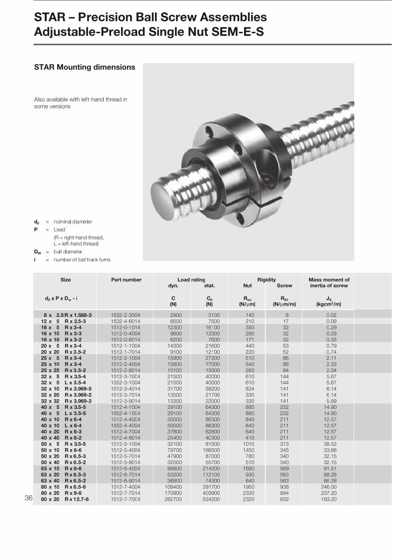
Adjustable-Preload Single Nut SEM-E-S
STAR Mounting dimensions
Also available with left-hand thread insome versions
d0 = nominal diameter
P = Lead
(R = right-hand thread,
L = left-hand thread)
DW = ball diameter
i = number of ball track turns

7/22/2019 Tornillo de Bolas BP-120
http://slidepdf.com/reader/full/tornillo-de-bolas-bp-120 37/68 37
L3
D 5
D 1 +
0 . 7
L
L5
D 1
3.4
ø 6
D 7
L4
α 6 0 °
D 7
D 6
S
α 6 0 °
D 7
D 6
S
L 3/2
Version for 8 x 2.5
Dimensions (mm) Angle α Weight
Screw Nut
Holesd1 d2 D1 D5 D6 n D7 L L3 L4 L5 S
f9 (number) (° ) (kg/m) (kg)
7.5 6.2 16 30 23 5 3.4 16 13 3 3 3.9 90 0.32 0.06
11.2 9.4 24 40 32 5 4.5 28 12 8 8 M6 35 0.70 0.11
15 12.9 28 53 40 5 6.6 35 15 10 10 M6 37 1.26 0.23
15 12.9 28 53 40 5 6.6 45 15 15 15 M6 270 1.26 0.25
15 12.9 33 58 45 5 6.6 45 15 15 15 M6 40 1.27 0.42
19 16.9 33 58 45 5 6.6 45 15 10 15 M6 34 2.06 0.33
19.3 16.7 38 63 50 5 6.6 57 20 18.5 18.5 M6 30 1.98 0.63
24 21.9 38 63 50 5 6.6 45 20 10 12.5 M6 30 3.33 0.44
24 21.9 38 63 50 5 6.6 64 20 16 22 M6 30 3.44 0.52
24 21.4 48 73 60 5 6.6 70 25 22.5 22.5 M6 42 3.16 1.13
31 28.4 48 73 60 5 6.6 48 20 10 14 M6 31 5.50 0.63
31 28.4 48 73 60 5 6.6 48 20 16 14 M6 31 5.50 0.63
31 27.9 48 73 60 5 6.6 77 20 28.5 28.5 M6 282 5.71 0.8731 27.9 56 80 68 5 6.6 64 20 22 22 M6 30 5.33 1.13
31 27.9 56 80 68 5 6.6 88 20 34 34 M6 30 5.49 1.44
39 36.4 56 80 68 5 6.6 54 20 10 17 M8x1 25 8.84 0.87
39 36.4 56 80 68 5 6.6 54 20 10 17 M8x1 25 8.84 0.87
38 33.8 63 95 78 5 9.0 70 25 16 22.5 M8x1 33 8.21 1.52
38 33.8 63 95 78 5 9.0 70 25 16 22.5 M8x1 33 8.21 1.52
38 33.8 63 95 78 5 9.0 88 25 25 31.5 M8x1 270 8.21 1.77
38 33.8 72 110 90 5 11.0 102 40 31 31 M8x1 41 8.21 3.77
49 46.4 68 98 82 5 9.0 54 25 10 14.5 M8x1 23 14.20 1.23
48 43.8 72 110 90 5 11.0 90 30 16 30 M8x1 29 13.40 2.44
48 43.3 85 125 105 5 11.0 92 30 25 31 M8x1 270 12.70 3.94
48 43.3 85 125 105 5 11.0 109 30 39.5 39.5 M8x1 30 12.70 4.42
61 56.8 85 125 105 5 11.0 90 30 16 30 M8x1 25 21.80 2.94
61 56.3 95 140 118 5 14.0 92 30 25 31 M8x1 260 21.00 4.44
61 56.3 95 140 118 5 14.0 109 30 39.5 39.5 M8x1 20 21.00 4.94
78 73.3 105 150 125 5 14.0 95 30 16 32.5 M8x1 23 35.70 4.1977 70.8 125 180 152 5 18.0 160 50 25 55 M8x1 30 32.40 13.79
76 67.0 125 180 152 5 18.0 170 50 25 60 M8x1 30 32.40 13.30
d 0
d 1
d 2
D w
right-hand thread left-hand thread
First angle projection

7/22/2019 Tornillo de Bolas BP-120
http://slidepdf.com/reader/full/tornillo-de-bolas-bp-120 38/6838
Size Part number Load ratings Rigidity Mass moment of
dyn. stat. Nut Screw inertia of screw
d0 x P x Dw - i C C0 Rnu RS1 JS
(N) (N) (N/ µm) (N/ µm/m) (kgcm2 /m)
8 x 2.5 R x 1 .588-3 1532-2-3002 2900 3100 140 8 0.02
12 x 5 R x 2.5-3 1532-4-6012 6500 7500 210 17 0.0916 x 5 R x 3-4 1512-0-1012 12300 16100 350 32 0.2916 x 10 R x 3-3 1512-0-4002 9600 12300 280 32 0.29
16 x 16 R x 3-2 1512-0-6012 6200 7600 171 32 0.33
20 x 5 R x 3-4 1512-1-1002 14300 21600 440 53 0.7920 x 20 R x 3.5-2 1512-1-7012 9100 12100 220 52 0.7425 x 5 R x 3-4 1512-2-1002 15900 27200 510 86 2.11
25 x 10 R x 3-4 1512-2-4002 15800 27000 540 86 2.33
25 x 25 R x 3.5-2 1512-2-8012 10100 15000 260 84 2.0425 x 25 R x 3.5-3* ) 1512-2-8052 14100 22300 375 84 2.0432 x 5 R x 3.5-4 1512-3-1002 21500 40000 610 144 5.67
32 x 10 R x 3.969-5 1512-3-4012 31700 58200 834 141 6.1432 x 20 R x 3.969-2 1512-3-7012 13500 21700 330 141 6.1432 x 20 R x 3.969-3* ) 1512-3-7052 19200 32800 475 141 6.1432 x 32 R x 3.969-2 1512-3-9012 13300 22000 330 141 5.89
32 x 32 R x 3.969-3* ) 1512-3-9052 19000 33100 470 141 5.89
40 x 5 R x 3.5-5 1512-4-1002 29100 64300 880 232 14.9040 x 10 R x 6-4 1512-4-4002 50000 86300 840 211 12.57
40 x 20 R x 6-3 1512-4-7002 37800 62800 640 211 12.57
40 x 40 R x 6-2 1512-4-9012 25400 40300 410 211 12.57
40 x 40 R x 6-3* ) 1512-4-9052 37100 62500 585 211 12.5750 x 5 R x 3.5-5 1512-5-1002 32100 81500 1010 373 38.5250 X 10 R X 6-6 1512-5-4002 79700 166500 1450 345 33.66
50 x 20 R x 6.5-3 1512-5-7012 47900 87000 780 340 32.15
63 x 10 R x 6-6 1512-6-4002 88800 214200 1690 569 91.51
* ) Outer diameter corresponds to DIN 69 051, Part 5, model code ZEM-E-A
STAR – Precision Ball Screw Assemblies
Cylindrical Single Nut ZEM-E-S and ZEM-E-A* )
Nut version:
with reduced backlash or preloaded by
means of optimized ball size selection
STAR Mounting dimensions
In some cases, the outer diameter has
been based on the centering diameter
to DIN 69 051.
d0 = nominal diameter
P = Lead
(R = right-hand thread,
L = left-hand thread)
DW = ball diameter
i = number of ball track turns

7/22/2019 Tornillo de Bolas BP-120
http://slidepdf.com/reader/full/tornillo-de-bolas-bp-120 39/68 39
Dimensions (mm) Max. Weight
backlash Screw Nut
d1 d2 D1 L L4 L6 L7 d4 b t1
g6 +0.1 +0.2 P9 +0.1 (mm) (kg/m) (kg)
7.5 6.3 16 16 6 5 3.5 2 3 1.8 0.02 0.32 0.02
11.2 9.4 24 28 12 10 7 4 5 3 0.03 0.70 0.06
15.0 12.9 28 35 12 14.5 9.5 4 5 3 0.04 1.26 0.09
15.0 12.9 28 45 16 14.5 9.5 4 5 3 0.04 1.26 0.12
15.0 12.9 33 45 16 14.5 9.5 4 5 3 0.04 1.27 0.20
19.0 16.9 33 45 16 14.5 9.5 4 5 3 0.04 2.06 0.16
19.3 16.7 38 64 20 22 9.5 4 5 3 0.04 1.98 0.34
24.0 21.9 38 45 16 14.5 9.5 4 5 3 0.04 3.33 0.19
24.0 21.9 38 64 20 22 9.5 4 5 3 0.04 3.44 0.28
24.0 21.4 48 80 20 30 10.5 4 5 3 0.04 3.16 0.73
24.0 21.4 40 95 20 37.5 10.5 4 5 3 0.04 3.29 0.50
31.0 28.4 48 48 20 14 9.5 4 5 3 0.04 5.50 0.32
31.0 27.9 48 77 20 28.5 9.5 4 5 3 0.04 5.71 0.50
31.0 27.9 56 64 20 22 9.5 4 5 3 0.04 5.33 0.74
31.0 27.9 50 84 20 32 9.5 4 5 3 0.04 5.63 0.66
31.0 27.9 56 88 20 34 9.5 4 5 3 0.04 5.49 1.03
31.0 27.9 50 120 20 50 9.5 4 5 3 0.04 5.56 0.97
39.0 36.4 56 54 20 17 9.5 4 5 3 0.04 8.84 0.44
38.0 33.8 63 70 20 25 14 4 5 3 0.07 8.21 0.88
38.0 33.8 63 88 20 34 14 4 5 3 0.07 8.21 1.13
38.0 33.8 72 113 20 46.5 14 4 5 3 0.07 8.21 2.23
38.0 33.8 63 142 20 61 14 4 5 3 0.07 8.21 1.85
49.0 46.4 68 54 20 17 9.5 4 5 3 0.04 14.20 0.62
48.0 43.8 72 90 20 35 14 5 5 3.0 0.07 13.40 1.34
48.0 43.3 85 92 32 30 14 5 6 3.5 0.07 12.70 2.39
61.0 56.8 85 90 32 29 14 5 5 3.5 0.07 21.80 1.59
d 0
d 1
d 2
D w
t1
L 7
L6 L4
d 4
L
b
D 1
First angle projection

7/22/2019 Tornillo de Bolas BP-120
http://slidepdf.com/reader/full/tornillo-de-bolas-bp-120 40/6840
Size Part number Load ratings Rigidity Mass moment ofdyn. stat. Nut Screw inertia of screw
d0 x P x Dw - i C C0 Rnu RS1 JS
(N) (N) (N/ µm) (N/ µm/m) (kgcm2 /m)
16 x 5 Rx 3-4 1502-0-1075 12300 16100 350 32 0.29
20 x 5 Rx 3-4 1502-1-1055 14300 21600 440 53 0.7925 x 5 Rx 3-4 1502-2-1055 15900 27200 510 86 2.1125 x 10 R x 3-4 1502-2-4055 15800 27000 540 86 2.33
32 x 5 R x 3.5-4 1502-3-1055 21500 40000 610 144 5.67
32 x 10 Rx 3.969-5 1502-3-4076 31700 58200 834 141 6.1440 x 5 R x 3.5-5 1502-4-1056 29100 64300 880 232 14.9040 x 10 R x 6-4 1502-4-4055 50000 86300 840 211 12.57
40 x 10 R x 6-6 1502-4-4056 72100 132200 1250 211 12.57
50 x 5 R x 3.5-5 1502-5-1056 32100 81500 1010 373 38.5250 x 10 R x 6-4 1502-5-4055 55400 109500 960 345 33.6650 x 10 R x 6-6 1502-5-4056 79700 166500 1450 345 33.66
50 x 20 R x 6.5-5 1502-5-7076 75700 149600 1300 340 32.1563 x 10 R x 6-4 1502-6-4055 61700 140400 1130 569 91.5163 x 10 R x 6-6 1502-6-4056 88800 214200 1690 569 91.5163 x 20 R x 6.5-5 1502-6-7076 83900 190300 1550 563 88.28
80 x 10 R x 6.5-6 1502-7-4056 108400 291700 1950 938 246.00
80 x 20 R x 9-6 1502-7-7076 170900 403900 2330 894 237.2080 x 20 Rx 12.7-6 1502-7-7056 262700 534200 2320 832 193.20
100 x 10 Rx 6.5-6 1502-8-4056 119500 371900 2200 1501 631.80
100 x 20 Rx 12.7-6 1502-8-7056 295100 686400 2760 1366 521.90
125 x 10 Rx 6.5-6 1502-9-4056 130600 468700 2390 2391 1606.00125 x 20 Rx 12.7-6 1502-9-7056 326500 870400 3180 2220 1380.00
Mounting dimensions
to DIN 69 051, Part 5
Flange type C
STAR – Precision Ball Screw Assemblies
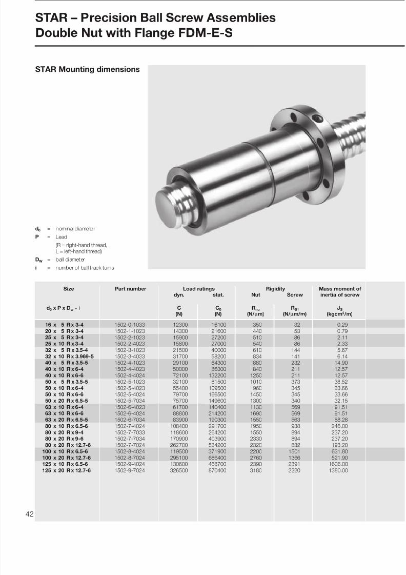
Double Nut with Flange FDM-E-C
d0 = nominal diameter
P = Lead
(R = right-hand thread,
L = left-hand thread)
DW = ball diameter
i = number of ball track turns

7/22/2019 Tornillo de Bolas BP-120
http://slidepdf.com/reader/full/tornillo-de-bolas-bp-120 41/68 41
L
D
L 4
D 5
D 1
L3
9 0 °
L 9
2 2 . 5
°
9 0 °
3 0 °
3 0 °
D7
D7
L 9
- 0 . 2
1
S
D 6
S
D 6
L 3/2
d0 ≤ 32
d0 ≥ 40
Dimensions (mm) Weight
Screw Nut
Holesd1 d2 D1 D5 D6 n D7 L L3 L4 L9 S
g6 (number) (kg/m) (kg)
15.0 12.9 28 48 38 6 5.5 72 12 10 44 M6 1.25 0.29
19.0 16.9 36 58 47 6 6.5 82 12 10 51 M6 2.05 0.53
24.0 21.9 40 62 51 6 6.5 82 12 10 55 M6 3.33 0.57
24.0 21.9 40 62 51 6 6.5 120 12 16 55 M6 3.44 0.77
31.0 28.4 50 80 65 6 9 88 13 10 71 M6 5.50 0.96
31.0 27.9 50 80 65 6 9 144 13 16 71 M6 5.71 1.34
39.0 36.4 63 93 78 8 9 100 15 10 81.5 M8x1 8.84 1.68
38.0 33.8 63 93 78 8 9 140 15 16 81.5 M8x1 8.21 2.15
38.0 33.8 63 93 78 8 9 180 15 16 81.5 M8x1 8.21 2.73
49.0 46.4 75 110 93 8 11 100 15 10 97.5 M8x1 14.12 2.25
48.0 43.8 75 110 93 8 11 140 18 16 97.5 M8x1 13.32 2.97
48.0 43.8 75 110 93 8 11 180 18 16 97.5 M8x1 13.32 3.73
48.0 43.3 75 110 93 8 11 255 18 25 97.5 M8x1 13.12 4.9361.0 56.8 90 125 108 8 11 140 22 16 110 M8x1 21.80 4.00
61.0 56.8 90 125 108 8 11 180 22 16 110 M8x1 21.80 4.45
61.0 56.3 95 135 115 8 13.5 255 22 25 117.5 M8x1 21.55 8.21
78.0 73.3 105 145 125 8 13.5 190 22 16 127.5 M8x1 35.72 5.93
77.0 70.8 125 165 145 8 13.5 320 25 25 147.5 M8x1 34.95 17.77
76.0 67.0 125 165 145 8 13.5 340 25 25 147.5 M8x1 32.42 19.40
98.0 93.4 125 165 145 8 13.5 190 25 16 147.5 M8x1 56.95 7.35
96.0 87.1 150 202 176 8 17.5 340 30 25 178.5 M8x1 52.74 24.60
123.0 118.0 150 202 176 8 17.5 190 25 16 178.5 M8x1 90.42 9.38
121.0 112.0 170 222 196 8 17.5 340 40 25 198.5 M8x1 85.07 29.70
d 0
d 1
d 2
D w
First angle projection
7/22/2019 Tornillo de Bolas BP-120
http://slidepdf.com/reader/full/tornillo-de-bolas-bp-120 42/6842
STAR Mounting dimensions
Size Part number Load ratings Rigidity Mass moment ofdyn. stat. Nut Screw inertia of screw
d0 x P x Dw - i C C0 Rnu RS1 JS
(N) (N) (N/ µm) (N/ µm/m) (kgcm2 /m)
16 x 5 Rx 3-4 1502-0-1033 12300 16100 350 32 0.29
20 x 5 Rx 3-4 1502-1-1023 14300 21600 440 53 0.7925 x 5 Rx 3-4 1502-2-1023 15900 27200 510 86 2.1125 x 10 R x 3-4 1502-2-4023 15800 27000 540 86 2.33
32 x 5 R x 3.5-4 1502-3-1023 21500 40000 610 144 5.67
32 x 10 Rx 3.969-5 1502-3-4033 31700 58200 834 141 6.1440 x 5 R x 3.5-5 1502-4-1023 29100 64300 880 232 14.9040 x 10 R x 6-4 1502-4-4023 50000 86300 840 211 12.57
40 x 10 R x 6-6 1502-4-4024 72100 132200 1250 211 12.57
50 x 5 R x 3.5-5 1502-5-1023 32100 81500 1010 373 38.5250 x 10 R x 6-4 1502-5-4023 55400 109500 960 345 33.6650 x 10 R x 6-6 1502-5-4024 79700 166500 1450 345 33.66
50 x 20 R x 6.5-5 1502-5-7034 75700 149600 1300 340 32.1563 x 10 R x 6-4 1502-6-4023 61700 140400 1130 569 91.5163 x 10 R x 6-6 1502-6-4024 88800 214200 1690 569 91.5163 x 20 R x 6.5-5 1502-6-7034 83900 190300 1550 563 88.28
80 x 10 R x 6.5-6 1502-7-4024 108400 291700 1950 938 246.00
80 x 20 R x 9-4 1502-7-7033 118600 264200 1550 894 237.2080 x 20 R x 9-6 1502-7-7034 170900 403900 2330 894 237.20
80 x 20 Rx 12.7-6 1502-7-7024 262700 534200 2320 832 193.20
100 x 10 Rx 6.5-6 1502-8-4024 119500 371900 2200 1501 631.80
100 x 20 Rx 12.7-6 1502-8-7024 295100 686400 2760 1366 521.90125 x 10 Rx 6.5-6 1502-9-4024 130600 468700 2390 2391 1606.00
125 x 20 Rx 12.7-6 1502-9-7024 326500 870400 3180 2220 1380.00
STAR – Precision Ball Screw Assemblies
Double Nut with Flange FDM-E-S
d0 = nominal diameter
P = Lead
(R = right-hand thread,
L = left-hand thread)
DW = ball diameter
i = number of ball track turns

7/22/2019 Tornillo de Bolas BP-120
http://slidepdf.com/reader/full/tornillo-de-bolas-bp-120 43/68 43
L
D
L 4
D 5
D 1
L3
- 0 . 2
1
6 x 6 0
° 3 0 º
D 6
D7
S 4 x 9
0 ° 4 5 °
S
D 6
D7
1 0 x 3 6 °
S
18º
D7
D 6
8 x 4 5
° 2 2 .5 º
S
D 6
D7
L 3/2
Dimensions (mm) Weight
Screw Nut
Holesd1 d2 D1 D5 D6 n D7 L L3 L4 S
g6 (number) (kg/m) (kg)
15.0 12.9 28 53 40 4 6.6 72 12 10 M6 1.26 0.33
19.0 16.9 33 58 45 6 6.6 82 12 10 M6 2.06 0.45
24.0 21.9 38 63 50 6 6.6 82 12 10 M6 3.33 0.53
24.0 21.9 38 63 50 6 6.6 120 12 16 M6 3.44 0.70
31.0 28.4 48 73 60 6 6.6 88 13 10 M6 5.50 0.84
31.0 27.9 48 73 60 6 6.6 146 13 16 M6 5.71 1.22
39.0 36.4 56 80 68 6 6.6 100 15 10 M8x1 8.84 1.13
38.0 33.8 63 95 78 6 9 140 15 16 M8x1 8.21 2.25
38.0 33.8 63 95 78 6 9 180 15 16 M8x1 8.21 2.83
49.0 46.4 68 98 82 6 9 100 15 10 M8x1 14.20 1.60
48.0 43.8 72 110 90 6 11 140 18 16 M8x1 13.40 2.74
48.0 43.8 72 110 90 6 11 180 18 16 M8x1 13.40 3.39
48.0 43.3 85 125 105 6 11 255 22 25 M8x1 12.70 6.7161.0 56.8 85 125 105 6 11 140 22 16 M8x1 21.80 3.53
61.0 56.8 85 125 105 6 11 180 22 16 M8x1 21.80 4.32
61.0 56.3 95 140 118 6 14 255 22 25 M8x1 21.00 8.65
78.0 73.3 105 150 125 6 14 190 22 16 M8x1 35.70 6.35
77.0 70.8 125 180 152 8 18 240 25 25 M8x1 32.40 14.80
77.0 70.8 125 180 152 8 18 320 25 25 M8x1 32.40 18.60
76.0 67.0 125 180 152 8 18 340 25 25 M8x1 32.40 20.20
98.0 93.4 125 180 152 8 18 190 25 16 M8x1 56.90 8.19
96.0 87.1 145 200 172 8 18 340 30 25 M8x1 52.70 24.50
123.0 118.0 150 210 180 8 18 190 30 16 M8x1 90.40 10.80
121.0 112.0 170 230 200 10 18 340 40 25 M8x1 85.10 31.00
d 0
d 1
d 2
D w
First angle projection
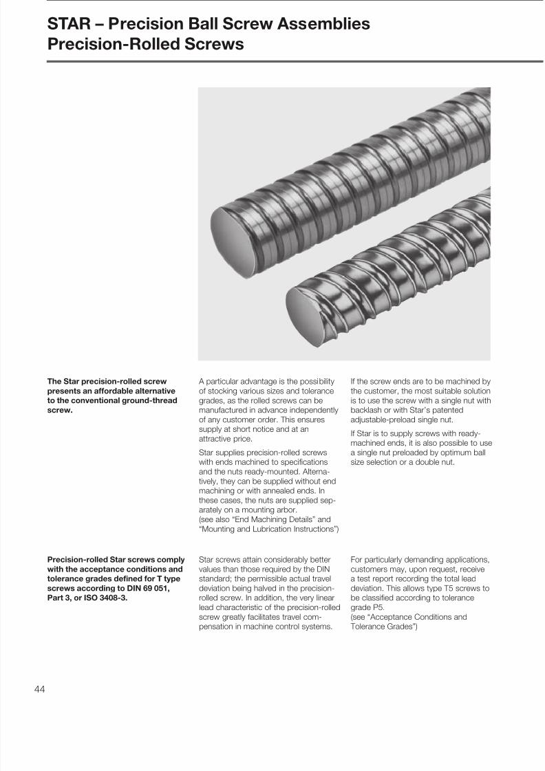
7/22/2019 Tornillo de Bolas BP-120
http://slidepdf.com/reader/full/tornillo-de-bolas-bp-120 44/68

7/22/2019 Tornillo de Bolas BP-120
http://slidepdf.com/reader/full/tornillo-de-bolas-bp-120 45/68 45
Size Part number Mass Maximum
Tolerance Tolerance Tolerance Rigidity Weight moment length
grade grade grade of inertia stan- ond0 x P x Dw T5 T7 T9 d1 d2 RS1 JS dard request
(mm) (mm) (N/ µm/m) (kg/m) (kgcm2 /m) (mm) (mm)
8 x 2.5 R x 1.588 1531-2-3500 1531-2-3700 1531-2-3900 7.5 6.3 8 0.31 0.0212 x 5 R x 2.5 1531-4-6500 1531-4-6700 1531-4-6900 11.2 9.4 17 0.70 0.0916 x 5 R x 3 1511-0-1500 1511-0-1700 1511-0-1900 15 12.9 32 1.25 0.29
16 x 10 R x 3 1511-0-4500 1511-0-4700 1511-0-4900 15 12.9 32 1.25 0.29
16 x 16 R x 3 1511-0-6510 1511-0-6710 1511-0-6910 15 12.9 32 1.30 0.3320 x 5 R x 3 1511-1-1500 1511-1-1700 1511-1-1900 19 16.9 53 2.05 0.7920 x 20 R x 3.5 1511-1-7510 1511-1-7710 1511-1-7910 19.3 16.7 52 2.04 0.74
25 x 5 R x 3 1511-2-1500 1511-2-1700 1511-2-1900 24 21.9 86 3.33 2.11
25 x 10 R x 3 1511-2-4500 1511-2-4700 1511-2-4900 24 21.9 86 3.44 2.3325 x 25 R x 3.5 1511-2-8510 1511-2-8710 1511-2-8910 24 21.4 84 3.29 2.0432 x 5 R x 3.5 1511-3-1500 1511-3-1700 1511-3-1900 31 28.4 144 5.50 5.67
32 x 5 L x 3.5 1551-3-1500 1551-3-1700 1551-3-1900 31 28.4 144 5.50 5.67
32 x 10 R x 3.969 1511-3-4510 1511-3-4710 1511-3-4910 31 27.9 141 5.63 6.1432 x 20 R x 3.969 1511-3-7510 1511-3-7710 1511-3-7910 31 27.9 141 5.63 6.1432 x 32 R x 3.969 1511-3-9510 1511-3-9710 1511-3-9910 31 27.9 141 5.56 5.89
40 x 5 R x 3.5 1511-4-1500 1511-4-1700 1511-4-1900 39 36.4 232 8.84 14.90
40 x 5 L x 3.5 1551-4-1500 1551-4-1700 1551-4-1900 39 36.4 232 8.84 14.9040 x 10 R x 6 1511-4-4500 1511-4-4700 1511-4-4900 38 33.8 211 8.21 12.5740 x 10 L x 6 1551-4-4500 1551-4-4700 1551-4-4900 38 33.8 211 8.21 12.57
40 x 20 R x 6 1511-4-7500 1511-4-7700 1511-4-7900 38 33.8 211 8.21 12.57
40 x 40 R x 6 1511-4-9510 1511-4-9710 1511-4-9910 38 33.8 211 8.21 12.5750 x 5 R x 3.5 1511-5-1500 1511-5-1700 1511-5-1900 49 46.4 373 14.12 38.5250 x 10 R x 6 1511-5-4500 1511-5-4700 1511-5-4900 48 43.8 345 13.32 33.66
50 x 20 R x 6.5 1511-5-7510 1511-5-7710 1511-5-7910 48 43.3 340 13.12 32.15
50 x 40 R x 6.5 1511-5-9510 1511-5-9710 1511-5-9910 48 43.3 340 13.12 32.1563 x 10 R x 6 1511-6-4500 1511-6-4700 1511-6-4900 61 56.8 569 21.80 91.51
63 x 20 R x 6.5 1511-6-7510 1511-6-7710 1511-6-7910 61 56.3 563 21.55 88.28
63 x 40 R x 6.5 1511-6-9510 1511-6-9710 1511-6-9910 61 56.3 563 21.55 88.28
80 x 10 R x 6.5 1511-7-4500 1511-7-4700 1511-7-4900 78 73.3 936 35.72 246.080 x 20 R x 9 1511-7-7510 1511-7-7710 1511-7-7910 77 70.8 894 34.95 237.2
1500
1800
2500
5600
3500
5600
7500
LG1
L
L G2L1
Please state lengths in the “Inquiry / Order Form”
L = overall length
L1 = threaded length
LG1
/LG2
= length of soft-annealed screw ends d 0
d 1
d 2
D w

7/22/2019 Tornillo de Bolas BP-120
http://slidepdf.com/reader/full/tornillo-de-bolas-bp-120 46/6846
Size Dimensions (mm) Keyway Fixed bearing
to DIN 6885 Angular contact thrust Pillow block unit
bearing with slotted nut completed0 x P d d1 d2 d3 d4 l1 l2 l3 bP9 x l x t ZKLN ZKLF
h5 h7 Part no. Part no. Part no.
8 x 2.5 6 7.5 6.3 M6x0.5 5 40 16 10 - 1590-1-0600 - 1591-1-0600
12 x 5 6 11.2 9.4 M6x0.5 5 40 16 10 - 1590-1-0600 - 1591-1-0620
16 x 5 10 15 12.9 M10x1 8 50 20 12 2 x 14 x 1.2 1590-1-1000 - 1591-1-1020
16 x10 10 15 12.9 M10x1 8 50 20 12 2 x 14 x 1.2 1590-1-1000 - 1591-1-1020
16 x16 10 15 12.4 M10x1 8 50 20 12 2 x 14 x 1.2 1590-1-1000 - 1591-1-1020
20 x 5 12 19 16.9 M12x1 10 60 25 12 3 x 20 x 1.8 1590-1-1200 1590-0-1200 1591-1-1220
20 x20 12 19.3 16.7 M12x1 10 60 25 12 3 x 20 x 1.8 1590-1-1200 1590-0-1200 1591-1-1220
25 x 5 17 24 21.9 M17x1 15 67 30 14 5 x 25 x 3 1590-1-1700 1590-0-1700 1591-1-1720
25 x10 17 24 21.9 M17x1 15 67 30 14 5 x 25 x 3 1590-1-1700 1590-0-1700 1591-1-1720
25 x25 17 24 21.4 M17x1 15 67 30 14 5 x 25 x 3 1590-1-1700 1590-0-1700 1591-1-1720
32 x 5 20 31 28.4 M20x1 15 80 40 14 5 x 28 x 3 1590-1-2000 1590-0-2000 1591-1-2020
32 x10 20 31 27.9 M20x1 15 80 40 14 5 x 28 x 3 1590-1-2000 1590-0-2000 1591-1-2020
32 x20 20 31 27.9 M20x1 15 80 40 14 5 x 28 x 3 1590-1-2000 1590-0-2000 1591-1-202032 x32 20 31 27.9 M20x1 15 80 40 14 5 x 28 x 3 1590-1-2000 1590-0-2000 1591-1-2020
40 x 5 30 39 36.4 M30x1.5 25 93 50 18 8 x 36 x 4 1590-1-3000 1590-0-3000 1591-1-3020
40 x10 25 38 33.8 M25x1.5 20 130 50 26 6 x 36 x 3.5 1590-2-2500 1590-3-2500 1591-2-2500
40 x 20 25 38 33.8 M25x1.5 20 130 50 26 6 x 36 x 3.5 1590-2-2500 1590-3-2500 1591-2-2500
40 x40 25 38 33.8 M25x1.5 20 130 50 26 6 x 36 x 3.5 1590-2-2500 1590-3-2500 1591-2-2500
Undercut form F DIN 509
For size 8 x 2.5Screw-shaft end friction welded
or pressed sleeve for bearing face
Fixed bearing end: angular contact thrust bearing ZKLN or ZKLF
Thread undercut DIN 76 short
2 d d d d
4
b x l x t
l2 l3
l1
P9
d 3
1 2
l1 15 max. 8
1
Details
on page 56
Details
on page 54
STAR – Precision Ball Screw Assemblies
End Machining Details

7/22/2019 Tornillo de Bolas BP-120
http://slidepdf.com/reader/full/tornillo-de-bolas-bp-120 47/68 47
Floating bearing end: deep-groove bearing to DIN 625
Size Dimensions (mm) Floating bearing
Deep-groove bearing Pillow block unit
with retaining ring completed0 x P d1 d2 d5 d6 l4 l5 l6 Part no. Part no.
j6 h11 h12 H13
8 x 2.5 7.5 6.3 5 4.8 7 5 0.7 1590-6-0500 1591-6-0500
12 x 5 11.2 9.4 6 5.7 8 6 0.8 1590-6-0600 1591-6-0620
16 x 5 15 12.9 10 9.6 12 9 1.1 1590-6-1000 1591-6-1020
16 x 10 15 12.9 10 9.6 12 9 1.1 1590-6-1000 1591-6-1020
16 x 16 15 12.4 10 9.6 12 9 1.1 1590-6-1000 1591-6-1020
20 x 5 19 16.9 12 11.5 13 10 1.1 1590-6-1200 1591-6-1220
20 x 20 19.3 16.7 12 11.5 13 10 1.1 1590-6-1200 1591-6-1220
25 x 5 24 21.9 17 16.2 15 12 1.1 1590-6-1700 1591-6-1720
25 x 10 24 21.9 17 16.2 15 12 1.1 1590-6-1700 1591-6-1720
25 x 25 24 21.4 17 16.2 15 12 1.1 1590-6-1700 1591-6-1720
32 x 5 31 28.4 20 19 18 14 1.3 1590-6-2000 1591-6-2020
32 x 10 31 27.9 20 19 18 14 1.3 1590-6-2000 1591-6-2020
32 x 20 31 27.9 20 19 18 14 1.3 1590-6-2000 1591-6-202032 x 32 31 27.9 20 19 18 14 1.3 1590-6-2000 1591-6-2020
40 x 5 39 36.4 30 28.6 20 16 1.6 1590-6-3000 1591-6-3020
40 x 10 38 33.8 30 28.6 20 16 1.6 1590-6-3000 1591-6-3010
40 x 20 38 33.8 30 28.6 20 16 1.6 1590-6-3000 1591-6-3010
40 x 40 38 33.8 30 28.6 20 16 1.6 1590-6-3000 1591-6-3010
Turned groove
for retaining ring DIN 471
d 5
l4
6 d 2
d 1
l5l6
d
Undercut form E DIN 509
Details
on page 60
Details
on page 62
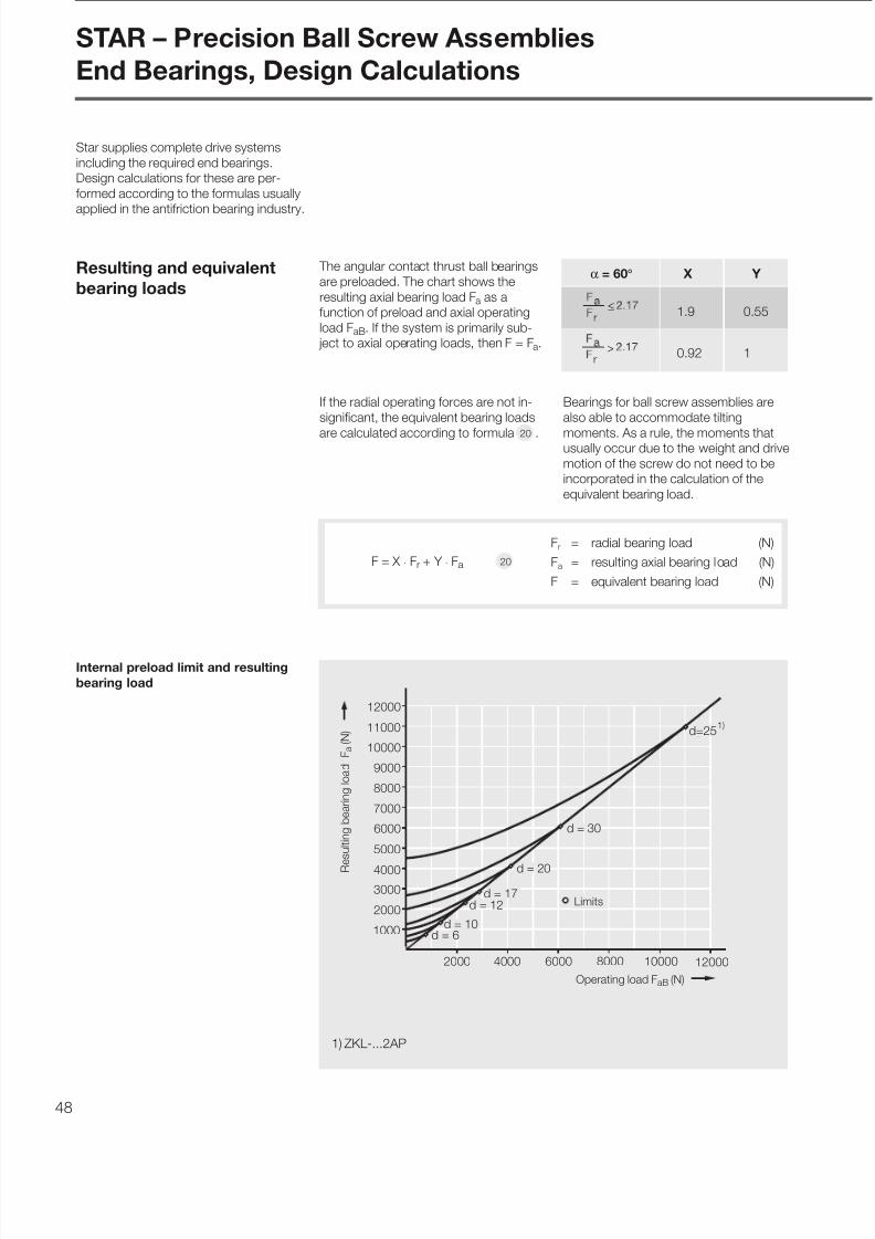
7/22/2019 Tornillo de Bolas BP-120
http://slidepdf.com/reader/full/tornillo-de-bolas-bp-120 48/6848
α = 60° X Y
1.9 0.55
0.92 1
F = X · Fr + Y · Fa
Bearings for ball screw assemblies are
also able to accommodate tilting
moments. As a rule, the moments thatusually occur due to the weight and drive
motion of the screw do not need to be
incorporated in the calculation of the
equivalent bearing load.
Resulting and equivalent
bearing loads
The angular contact thrust ball bearings
are preloaded. The chart shows the
resulting axial bearing load Fa as a
function of preload and axial operating
load FaB. If the system is primarily sub-
ject to axial operating loads, then F = Fa.
STAR – Precision Ball Screw Assemblies
End Bearings, Design Calculations
≤
>
Fr = radial bearing load (N)
Fa = resulting axial bearing load (N)
F = equivalent bearing load (N)
Star supplies complete drive systems
including the required end bearings.
Design calculations for these are per-
formed according to the formulas usually
applied in the antifriction bearing industry.
d = 12
2000 4000 6000
1000
2000
3000
4000
5000
6000
7000
8000
9000
10000
11000
12000
8000 10000 12000
d = 30
d = 20
10d=25
d = 17
d = 6d = 10
1)
Operating load FaB (N)
Resultingbearingload
Fa
(N)
Limits
Internal preload limit and resulting
bearing load
1) ZKL-...2AP
If the radial operating forces are not in-
significant, the equivalent bearing loads
are calculated according to formula .20
20
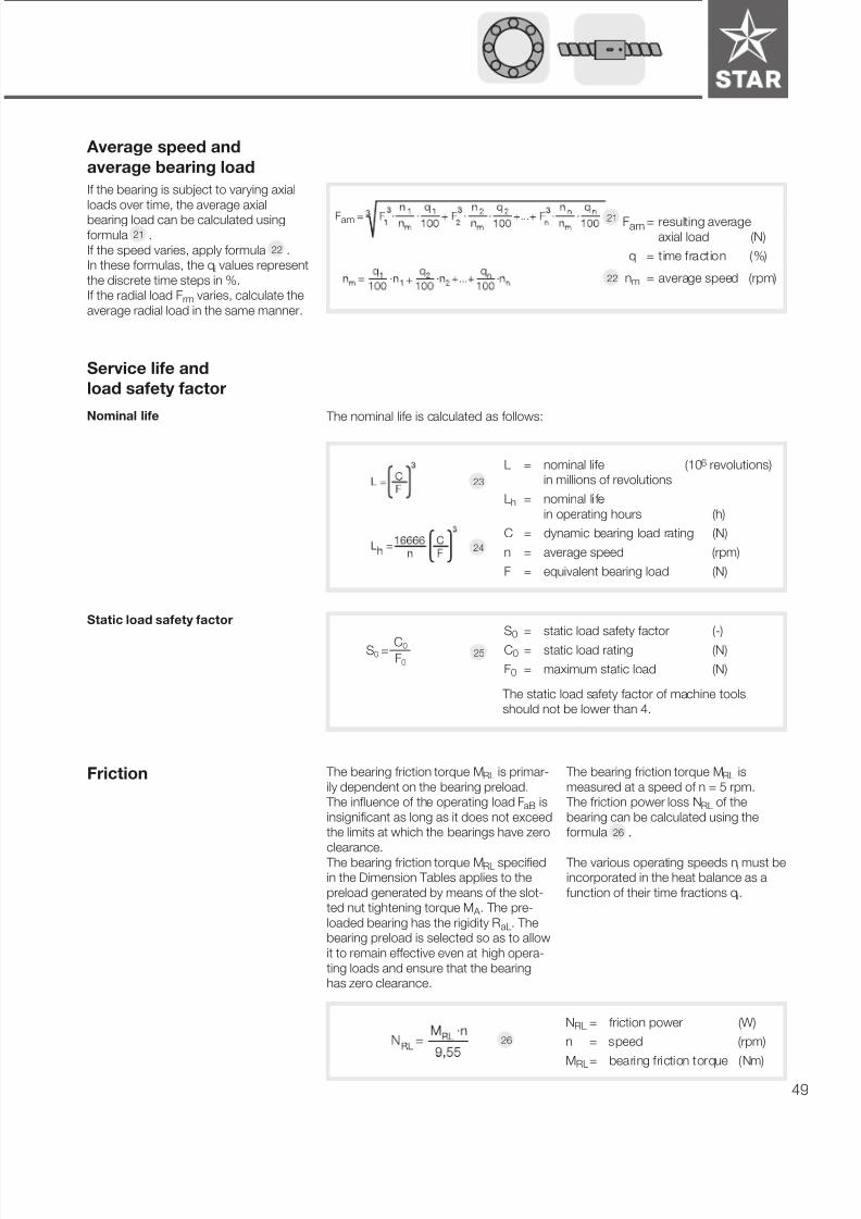
7/22/2019 Tornillo de Bolas BP-120
http://slidepdf.com/reader/full/tornillo-de-bolas-bp-120 49/68 49
Nominal life The nominal life is calculated as follows:
Service life and
load safety factor
S0 = static load safety factor (-)
C0 = static load rating (N)
F0 = maximum static load (N)
Static load safety factor
L = nominal life (106 revolutions)
in millions of revolutions
Lh = nominal li fe
in operating hours (h)
C = dynamic bearing load rating (N)
n = average speed (rpm)
F = equivalent bearing load (N)
S0 = C0
F0
23
24
25
Average speed and
average bearing load
If the bearing is subject to varying axial
loads over time, the average axial
bearing load can be calculated using
formula .
If the speed varies, apply formula .
In these formulas, the qi values represent
the discrete time steps in %.
If the radial load Frm varies, calculate the
average radial load in the same manner.
Fam = resulting average
axial load (N)
q = time fraction (%)
nm = average speed (rpm)+
21
22
The bearing friction torque MRL is primar-
ily dependent on the bearing preload.
The influence of the operating load FaB is
insignificant as long as it does not exceed
the limits at which the bearings have zero
clearance.
The bearing friction torque MRL specified
in the Dimension Tables applies to the
preload generated by means of the slot-
ted nut tightening torque M A . The pre-
loaded bearing has the rigidity RaL. The
bearing preload is selected so as to allow
it to remain effective even at high opera-
ting loads and ensure that the bearing
has zero clearance.
Friction The bearing friction torque MRL is
measured at a speed of n = 5 rpm.
The friction power loss NRL of the
bearing can be calculated using the
formula .
The various operating speeds ni must be
incorporated in the heat balance as a
function of their time fractions qi.
NRL = friction power (W)
n = speed (rpm)
MRL
= bearing friction torque (Nm)
Fam
21
22
The static load safety factor of machine tools
should not be lower than 4.
26
26

7/22/2019 Tornillo de Bolas BP-120
http://slidepdf.com/reader/full/tornillo-de-bolas-bp-120 50/6850
Screw end Housing
IT4 A
A
C
IT4
1.6
C
IT5
1.6IT3
0.8
0.8
d I T 5
D J 6
For customer-machined screw ends,
please observe the design notes given
for screw ends and housings.
See “End Machining Details” for Star
screw end designs.
Lubrication Bearings for ball screw assemblies are
lubricated with grease for a lifetime of
reliable service. It should be noted,
however, that grease lubrication doesnot facilitate the dissipation of heat in the
bearings. The bearing temperature
should therefore not exceed 50°C,
particularly in machine tool applications.
Angular contact thrust ball bearings
series ZKLN, ZKLF are lubricated for life
with grease KPE2K to DIN 51825.
This eliminates all drawbacks associated
with in-service lubrication such as over-greasing or the use of an unsuitable type
of grease.
Accuracy
STAR – Precision Ball Screw Assemblies
End Bearings, Design Notes
Bearing Design
ZKLN... .2RS 2AP
ZKLF... .2RS 2AP
ZKLN... .2RS PE
ZKLF... .2RS PE
Series Bore Axial Radial Tolerance ( µm)
DJ6 run-out clearance
Bore Outer Width
(mm) ( µm) diameter
≤ 50 > 50
+3≤ 10 preloaded -10 -250-5
> 10 preloaded -10 -11 -13 -250
≤ 25
preloaded -5 -10 -500
> 25
P5 to
DIN 620
P5 toDIN 620
2.5
2

7/22/2019 Tornillo de Bolas BP-120
http://slidepdf.com/reader/full/tornillo-de-bolas-bp-120 51/68 51
Mounting
Angular contact thrust ball bearings
and deep-groove ball bearings
Outer raceway markings
for paired bearings
End Bearings,
Mounting Instructions
When mounting angular contact thrust
ball bearings Series ZKLN and ZKLF,
ensure that the mounting forces are only
exerted on the bearing rings.
Never apply mounting forces via the
antifriction bearing elements or the seal
rings!
The two sections of the inner raceway
may not be separated during assembly
or disassembly for any reason.
Tighten mounting screws for screw-
down or flange-mounted bearings in
crosswise sequence.
The mounting screws may only be
subject to tension amounting to a
maximum of 70% of their yielding point.
The screw-down (ZKLF) bearings have a
groove on the cylindrical surface of the
outer raceway for disassembly. The
individual bearings of the bearing pairseries ZKLN...2AP and ZKLF...2AP are
marked on the cylindrical surfaces of the
outer raceways (see diagram).
The markings reveal the bearing
sequence. The sealing rings should
face outward after proper assembly.
Slotted nut The bearings are preloaded by tightening
the nuts ZM.
In order to prevent settling phenomena,
we recommend first tightening the
slotted nut by 2 times the tightening
torque M A and then easing the load.Only then should the slotted nut be
retightened to the specified tightening
torque M A .
The two counter set screws are then
alternately tightened using a hexagon
socket wrench.
The components are disassembled in
the reverse order, i.e., the counter set
screws are to be removed before the
slotted nut.
The slotted nuts can be reused several
times when properly assembled and
disassembled by competent personnel.
The inner raceways of the bearings are
dimensioned in such a way as to achieve
a defined bearing preload sufficient formost applications when the slotted
nut is tightened (M A in accordance with
Dimension Table).

7/22/2019 Tornillo de Bolas BP-120
http://slidepdf.com/reader/full/tornillo-de-bolas-bp-120 52/6852
STAR – Precision Ball Screw Assemblies
End Bearings, Mounting
Slotted nut Housing nut
Size Designa- Dimensions (mm) Dimensions (mm)
tion
M A FaB Weight M AG
d0 x P d D B d1 c m b t e f g (Nm) (kN) (g) (Nm) D1 D2 B4
8 x 2.5 ZM 06 M6 x 0.5 16 8 12 4 M4 3 2 11 2.5 3.5 2.0 17 10 2 - 2.5 M26 x 1.5 16.5 8
12 x 5 ZM 06 M6 x 0.5 16 8 12 4 M4 3 2 11 2.5 3.5 2.0 17 10 2 - 2.5 M26 x 1.5 16.5 8
16 x 5 ZM 10 M10 x 1 18 8 14 4 M4 3 2 14 2.5 3.5 6.0 31 10 2 - 2.5 M36 x 1.5 22 8
16 x 10 ZM 10 M10 x 1 18 8 14 4 M4 3 2 14 2.5 3.5 6.0 31 10 2 - 2.5 M36 x 1.5 22 8
16 x 16 ZM 10 M10 x 1 18 8 14 4 M4 3 2 14 2.5 3.5 6.0 31 10 2 - 2.5 M36 x 1.5 22 8
20 x 5 ZM 12 M12 x 1 22 8 18 4 M4 3 2 17 2.5 3.5 8.0 38 15 2 - 2.5 M45 x 1.5 28 8
20 x 20 ZM 12 M12 x 1 22 8 18 4 M4 3 2 17 2.5 3.5 8.0 38 15 2 - 2.5 M45 x 1.5 28 8
25 x 5 ZM 17 M17 x 1 28 10 23 5 M5 4 2 22.5 3 4 15.0 57 28 4 - 5 M50 x 1.5 31 10
25 x 10 ZM 17 M17 x 1 28 10 23 5 M5 4 2 22.5 3 4 15.0 57 28 4 - 5 M50 x 1.5 31 10
25 x 25 ZM 17 M17 x 1 28 10 23 5 M5 4 2 22.5 3 4 15.0 57 28 4 - 5 M50 x 1.5 31 10
32 x 5 ZM 20 M20 x 1 32 10 27 5 M5 4 2 26 3 4 18.0 69 35 4 - 5 M55 x 1.5 36 10
32 x 10 ZM 20 M20 x 1 32 10 27 5 M5 4 2 26 3 4 18.0 69 35 4 - 5 M55 x 1.5 36 1032 x 20 ZM 20 M20 x 1 32 10 27 5 M5 4 2 26 3 4 18.0 69 35 4 - 5 M55 x 1.5 36 10
32 x 32 ZM 20 M20 x 1 32 10 27 5 M5 4 2 26 3 4 18.0 69 35 4 - 5 M55 x 1.5 36 10
40 x 5 ZM 30 M30 x 1.5 45 12 40 6 M6 5 2 37.5 4 5 32.0 112 75 8 - 10 M65 x 1.5 47 12
40 x 10 ZMA 25/45 M25 x 1.5 45 20 40 10 M6 5 2 35 4 5 25.0 211 160 8 - 10 M62 x 1.5 43 10
40 x 20 ZMA 25/45 M25 x 1.5 45 20 40 10 M6 5 2 35 4 5 25.0 211 160 8 - 10 M62 x 1.5 43 10
40 x 40 ZMA 25/45 M25 x 1.5 45 20 40 10 M6 5 2 35 4 5 25.0 211 160 8 - 10 M62 x 1.5 43 10
D d
t
d 1
f
0.5
g
B
m
c b
e
4 5 °
0.005 A
A
D 2
D 1
B4
Slotted nut
Housing nut
Slotted Nut and Housing
Nut for Fixed Bearing Thread pin
M A = tightening torque for slotted nut
FaB = axial fracture load for slotted nut
M AG = tightening torque for set screw
First angle projection

7/22/2019 Tornillo de Bolas BP-120
http://slidepdf.com/reader/full/tornillo-de-bolas-bp-120 53/68 53
O2O1 O 3 O 4
h
Mounting screws Locating pins
Mounting the Housing
Tighten the pillow block mounting
screws in crosswise sequence.
See table for tightening torque.
The housing nut fixes the entire bearing
unit in the housing.
Use screws and pins to fix the bearing
housing in place.
Size h O1 O2 O3
DIN 912 DIN 912 Tapered pin
(hardened)
O4
Straight pin
d0 x P (mm) (DIN 6325)
8 x 2.5 8 M5 x 20 M6 x 16 4 x 20
12 x 5 8 M5 x 20 M6 x 16 4 x 20
16 x 5 11 M8 x 35 M10 x 25 8 x 40
16 x 10 11 M8 x 35 M10 x 25 8 x 4016 x 16 11 M8 x 35 M10 x 25 8 x 40
20 x 5 11 M8 x 35 M10 x 25 8 x 40
20 x 20 11 M8 x 35 M10 x 25 8 x 40
25 x 5 14 M10 x 40 M12 x 30 10 x 50
25 x 10 14 M10 x 40 M12 x 30 10 x 5025 x 25 14 M10 x 40 M12 x 30 10 x 50
32 x 5 14 M10 x 40 M12 x 30 10 x 50
32 x 10 14 M10 x 40 M12 x 30 10 x 5032 x 20 14 M10 x 40 M12 x 30 10 x 50
32 x 32 14 M10 x 40 M12 x 30 10 x 50
40 x 5 16 M12 x 50 M14 x 35 10 x 5040 x 10 16 M12 x 50 M14 x 35 10 x 5040 x 20 16 M12 x 50 M14 x 35 10 x 50
40 x 40 16 M12 x 50 M14 x 35 10 x 50
Strength class for O1; O2 M5 M6 M8 M10 M12 M14
8.8 5.5 9.5 23 46 80 125
12.9 9.5 16 39 77 135 215
Nm
Take care to align the screw,
nut assembly, bearings and
guideway precisely with one
another.

7/22/2019 Tornillo de Bolas BP-120
http://slidepdf.com/reader/full/tornillo-de-bolas-bp-120 54/6854
Double-thrust, screw-down,
Series ZKLF... .2RS PE
The fixed bearing consists of:
- angular contact thrust ball
bearing ZKLF
- slotted nut ZM...
60° contact angle, preloaded, sealed and
lubricated for life.
Size Angular contact thrust bearing Slotted nut Load ratings Bearing friction Rigidity Rigidity
incl. torque with (axial) against tilting
slotted nut dyn. stat. sealing discd0 x P Designa- C C0 MRL RaL RkL
Part no. Designation tion (N) (N) (Nm) (N/ µm) (Nm/mrad)
20 x 5 1590-0-1200 ZKLF 1255.2RS PE ZM 12 17000 24700 0.16 375 50
20 x 20 1590-0-1200 ZKLF 1255.2RS PE ZM 12 17000 24700 0.16 375 50
25 x 5 1590-0-1700 ZKLF 1762.2RS PE ZM 17 18800 31000 0.24 450 80
25 x 10 1590-0-1700 ZKLF 1762.2RS PE ZM 17 18800 31000 0.24 450 80
25 x 25 1590-0-1700 ZKLF 1762.2RS PE ZM 17 18800 31000 0.24 450 80
32 x 5 1590-0-2000 ZKLF 2068.2RS PE ZM 20 26000 47000 0.30 650 140
32 x 10 1590-0-2000 ZKLF 2068.2RS PE ZM 20 26000 47000 0.30 650 140
32 x 20 1590-0-2000 ZKLF 2068.2RS PE ZM 20 26000 47000 0.30 650 140
32 x 32 1590-0-2000 ZKLF 2068.2RS PE ZM 20 26000 47000 0.30 650 140
40 x 5 1590-0-3000 ZKLF 3080.2RS PE ZM 30 29000 64000 0.50 850 300
40 x 10 1590-3-2500 ZKLF 2575.2RS2AP ZMA 25/45 45000 110000 0.60 1300 450
40 x 20 1590-3-2500 ZKLF 2575.2RS2AP ZMA 25/45 45000 110000 0.60 1300 450
40 x 40 1590-3-2500 ZKLF 2575.2RS2AP ZMA 25/45 45000 110000 0.60 1300 450
Double-thrust, screw-down,
paired
Series ZKLF... .2RS2AP
Fixed bearing with angular
contact thrust ball bearing
Details
on page 52
STAR – Precision Ball Screw Assemblies
End Bearings, Fixed Bearing ZKLF

7/22/2019 Tornillo de Bolas BP-120
http://slidepdf.com/reader/full/tornillo-de-bolas-bp-120 55/68 55
r 0. 6
L
D a d
m i n
.
d
B
r 0 .3
m i n . a
D
3
M6
t
3
d
J
r 0. 6
L
a d
m i n.
3
d
B
r 0 .3
m i n .
a D
3
M6
d D
J
tZKLF... .2RS PE
ZKLF... .2RS2AP
Dimensions (mm) Weight
Location shoulders complete
Holesd D B J Da da L n d3 t
-0.010 -0.013 -0.25 min. max. min. max. (number) ( ° ) (kg)
12 55 25 42 30 33 16 29 17 3 6.5 120
12 55 25 42 30 33 16 29 17 3 6.5 120
17 62 25 48 34 37 23 33 17 3 6.5 120
17 62 25 48 34 37 23 33 17 3 6.5 120 0.478
17 62 25 48 34 37 23 33 17 3 6.5 120
20 68 28 53 40 43 25 39 19 4 6.5 90
20 68 28 53 40 43 25 39 19 4 6.5 90
20 68 28 53 40 43 25 39 19 4 6.5 90
20 68 28 53 40 43 25 39 19 4 6.5 90
30 80 28 63 50 53 40 49 19 6 6.5 60 0.855
25 75 56 58 45 48 32 44 47 8 6.5 45 1.6
25 75 56 58 45 48 32 44 47 8 6.5 45 1.6
25 75 56 58 45 48 32 44 47 8 6.5 45 1.6
0.645
0.385
First angle projections
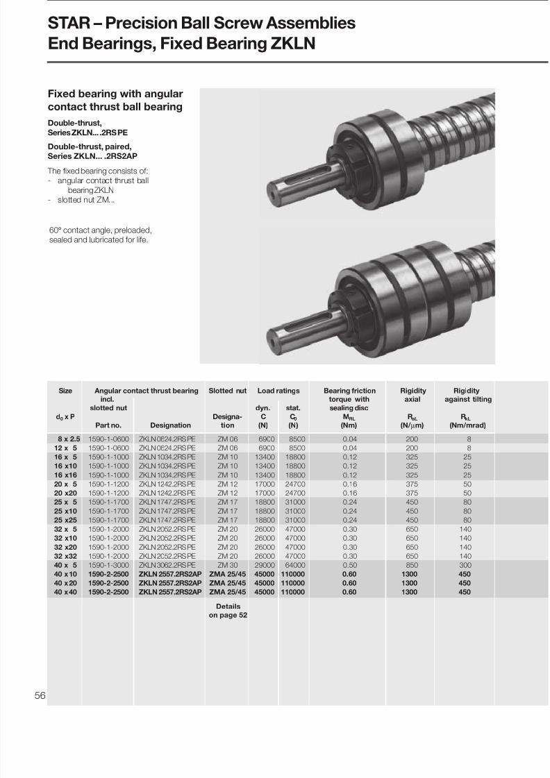
7/22/2019 Tornillo de Bolas BP-120
http://slidepdf.com/reader/full/tornillo-de-bolas-bp-120 56/6856
Double-thrust,
Series ZKLN... .2RS PE
STAR – Precision Ball Screw Assemblies
End Bearings, Fixed Bearing ZKLN
Size Angular contact thrust bearing Slotted nut Load ratings Bearing friction Rigidity Rigidity
incl. torque with axial against tilting
slotted nut dyn. stat. sealing discd0 x P Designa- C C0 MRL RaL RkL
Part no. Designation tion (N) (N) (Nm) (N/ µm) (Nm/mrad)
8 x 2.5 1590-1-0600 ZKLN 0624.2RS PE ZM 06 6900 8500 0.04 200 8
12 x 5 1590-1-0600 ZKLN 0624.2RS PE ZM 06 6900 8500 0.04 200 8
16 x 5 1590-1-1000 ZKLN 1034.2RS PE ZM 10 13400 18800 0.12 325 25
16 x10 1590-1-1000 ZKLN 1034.2RS PE ZM 10 13400 18800 0.12 325 25
16 x16 1590-1-1000 ZKLN 1034.2RS PE ZM 10 13400 18800 0.12 325 25
20 x 5 1590-1-1200 ZKLN 1242.2RS PE ZM 12 17000 24700 0.16 375 50
20 x20 1590-1-1200 ZKLN 1242.2RS PE ZM 12 17000 24700 0.16 375 50
25 x 5 1590-1-1700 ZKLN 1747.2RS PE ZM 17 18800 31000 0.24 450 80
25 x10 1590-1-1700 ZKLN 1747.2RS PE ZM 17 18800 31000 0.24 450 80
25 x25 1590-1-1700 ZKLN 1747.2RS PE ZM 17 18800 31000 0.24 450 80
32 x 5 1590-1-2000 ZKLN 2052.2RS PE ZM 20 26000 47000 0.30 650 140
32 x10 1590-1-2000 ZKLN 2052.2RS PE ZM 20 26000 47000 0.30 650 140
32 x20 1590-1-2000 ZKLN 2052.2RS PE ZM 20 26000 47000 0.30 650 14032 x32 1590-1-2000 ZKLN 2052.2RS PE ZM 20 26000 47000 0.30 650 140
40 x 5 1590-1-3000 ZKLN 3062.2RS PE ZM 30 29000 64000 0.50 850 300
40 x10 1590-2-2500 ZKLN 2557.2RS2AP ZMA 25/45 45000 110000 0.60 1300 450
40 x20 1590-2-2500 ZKLN 2557.2RS2AP ZMA 25/45 45000 110000 0.60 1300 450
40 x40 1590-2-2500 ZKLN 2557.2RS2AP ZMA 25/45 45000 110000 0.60 1300 450
The fixed bearing consists of:
- angular contact thrust ball
bearing ZKLN
- slotted nut ZM...
Double-thrust, paired,
Series ZKLN... .2RS2AP
Fixed bearing with angular
contact thrust ball bearing
Details
on page 52
60° contact angle, preloaded,
sealed and lubricated for life.
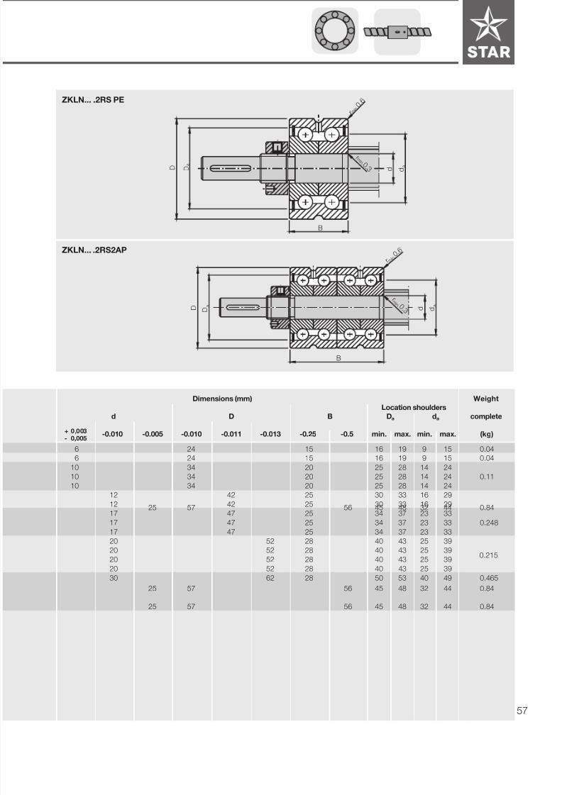
7/22/2019 Tornillo de Bolas BP-120
http://slidepdf.com/reader/full/tornillo-de-bolas-bp-120 57/68 57
+ 0,003- 0,005
Dimensions (mm) Weight
Location shoulders
d D B Da da complete
-0.010 -0.005 -0.010 -0.011 -0.013 -0.25 -0.5 min. max. min. max. (kg)
6 24 15 16 19 9 15 0.04
6 24 15 16 19 9 15 0.04
10 34 20 25 28 14 24
10 34 20 25 28 14 24 0.11
10 34 20 25 28 14 24
12 42 25 30 33 16 29
12 42 25 30 33 16 29
17 47 25 34 37 23 33
17 47 25 34 37 23 33 0.248
17 47 25 34 37 23 33
20 52 28 40 43 25 39
20 52 28 40 43 25 39
20 52 28 40 43 25 3920 52 28 40 43 25 39
30 62 28 50 53 40 49 0.465
25 57 56 45 48 32 44 0.84
25 57 56 45 48 32 44 0.84
B
a D D
a d d
m i n .
r 0 .3
m i n
.
r 0 . 6
d a
r 0. 6
m i n
.
r 0 .3
m i n .
D a
D
B
d
ZKLN... .2RS PE
ZKLN... .2RS2AP
25 57 56 45 48 32 44 0.84
0.215

7/22/2019 Tornillo de Bolas BP-120
http://slidepdf.com/reader/full/tornillo-de-bolas-bp-120 58/6858
ZKLN… .2RS PE
Pillow block unit Angular contact thrust bearing Slotted nut Weight
Size Part no. Load ratings (axial) Dimensions Designation M A Designation complete
dyn. stat. (mm)d0 x P complete C C0 d D B
(N) (N) (Nm) (kg)
8 x 2.5 1591-1-0600 6900 8500 6 24 15 ZKLN 0624.2RS PE 2.0 ZM 06 0.38
12 x 5 1591-1-0620 6000 8500 6 24 15 ZKLN 0624.2RS PE 2.0 ZM 06 0.38
16 x 5 1591-1-1020 13400 18800 10 34 20 ZKLN 1034.2RS PE 6.0 ZM 10 0.87
16 x10 1591-1-1020 13400 18800 10 34 20 ZKLN 1034.2RS PE 6.0 ZM 10 0.87
16 x16 1591-1-1020 13400 18800 10 34 20 ZKLN 1034.2RS PE 6.0 ZM 10 0.87
20 x 5 1591-1-1220 17000 24700 12 42 25 ZKLN 1242.2RS PE 8.0 ZM 12 1.12
20 x20 1591-1-1220 17000 24700 12 42 25 ZKLN 1242.2RS PE 8.0 ZM 12 1.12
25 x 5 1591-1-1720 18800 31000 17 47 25 ZKLN 1747.2RS PE 15.0 ZM 17 1.65
25 x10 1591-1-1720 18800 31000 17 47 25 ZKLN 1747.2RS PE 15.0 ZM 17 1.65
25 x25 1591-1-1720 18800 31000 17 47 25 ZKLN 1747.2RS PE 15.0 ZM 17 1.65
32 x 5 1591-1-2020 26000 47000 20 52 28 ZKLN 2052.2RS PE 18.0 ZM 20 1.93
32 x10 1591-1-2020 26000 47000 20 52 28 ZKLN 2052.2RS PE 18.0 ZM 20 1.93
32 x20 1591-1-2020 26000 47000 20 52 28 ZKLN 2052.2RS PE 18.0 ZM 20 1.9332 x32 1591-1-2020 26000 47000 20 52 28 ZKLN 2052.2RS PE 18.0 ZM 20 1.93
40 x 5 1591-1-3020 29000 64000 30 62 28 ZKLN 3062.2RS PE 32.0 ZM 30 2.64
40 x10 1591-2-2500 45000 110000 25 57 56 ZKLN 2557.2RS2AP 25.0 ZMA 25/45 5.13
40 x20 1591-2-2500 45000 110000 25 57 56 ZKLN 2557.2RS2AP 25.0 ZMA 25/45 5.13
40 x40 1591-2-2500 45000 110000 25 57 56 ZKLN 2557.2RS2AP 25.0 ZMA 25/45 5.13
ZKLN... .2RS2AP
The pillow block unit consists of:
- precision pillow block housing with
reference edges on both sides
- angular contact thrust ball
bearing ZKLN...
- slotted nut with two set screws
- housing nut with set screw
Slotted nut is enclosed separately.
Pillow block unit - fixed
bearing with angular
contact thrust ball bearing
Details
on page 52
STAR – Precision Ball Screw Assemblies
End Bearings, Pillow Block Unit - Fixed Bearing ZKLN

7/22/2019 Tornillo de Bolas BP-120
http://slidepdf.com/reader/full/tornillo-de-bolas-bp-120 59/68 59
ZKLN… .2RS PE
ZKLN... .2RS2AP
Dimensions (mm)
M L2 L3 L4 H1 H2 H3 H4 H5 B1 B2 B3 B4 B5 V S1 S2 S3 D1 D2 D3 P
js7 ±0.02 H12
31 - 38 50 34 18 13 8 9 32 16 8.5 8 16 6 5.3 M6 3.7 M26 x 1.5 16.5 18 0.1
31 36 38 50 41 22 13 10 9 32 16 8.5 8 16 6 5.3 M6 3.7 M26 x 1.5 16.5 18 0.1
43 50 52 68 58 32 22 14 15 37 23 8.5 7 18.5 8 8.4 M10 7.7 M36 x 1.5 22 22 0.15
43 50 52 68 58 32 22 14 15 37 23 8.5 7 18.5 8 8.4 M10 7.7 M36 x 1.5 22 22 0.15
43 50 52 68 58 32 22 14 15 37 23 8.5 7 18.5 8 8.4 M10 7.7 M36 x 1.5 22 22 0.15
47 58 60 77 64 34 22 16 15 42 25 8.5 8.5 21 8 8.4 M10 7.7 M45 x 1.5 28 26 0.15
47 58 60 77 64 34 22 16 15 42 25 8.5 8.5 21 8 8.4 M10 7.7 M45 x 1.5 28 26 0.15
54 64 66 88 72 39 27 18 18 46 29 10.5 8.5 23 10 10.5 M12 9.7 M50 x 1.5 31 32 0.2
54 64 66 88 72 39 27 18 18 46 29 10.5 8.5 23 10 10.5 M12 9.7 M50 x 1.5 31 32 0.2
54 64 66 88 72 39 27 18 18 46 29 10.5 8.5 23 10 10.5 M12 9.7 M50 x 1.5 31 32 0.2
56 68 70 92 77 42 27 19 18 49 29 10.5 10.0 24.5 10 10.5 M12 9.7 M55 x 1.5 36 36 0.2
56 68 70 92 77 42 27 19 18 49 29 10.5 10.0 24.5 10 10.5 M12 9.7 M55 x 1.5 36 36 0.2
56 68 70 92 77 42 27 19 18 49 29 10.5 10.0 24.5 10 10.5 M12 9.7 M55 x 1.5 36 36 0.256 68 70 92 77 42 27 19 18 49 29 10.5 10.0 24.5 10 10.5 M12 9.7 M55 x 1.5 36 36 0.2
63 78 80 105 90 50 32 22 21 53 32 12.5 10.5 26.5 12 12.6 M14 9.7 M65 x 1.5 48 48 0.2
63 82 80 105 98 58 32 23 21 89 62 20.5 13.5 44.5 12 12.6 M14 9.7 M62 x 1.5 43 48 0.2
63 82 80 105 98 58 32 23 21 89 62 20.5 13.5 44.5 12 12.6 M14 9.7 M62 x 1.5 43 48 0.2
63 82 80 105 98 58 32 23 21 89 62 20.5 13.5 44.5 12 12.6 M14 9.7 M62 x 1.5 43 48 0.2
First angle projections B 1
B 2
L 4
ø
2 x S 3
D 2
ø5
D 3
D D 1
d
BB3
D 2
ø5
D 3
D D 1
d
BB3
V
2
H 5
S
2 x M
H 3 H
2
H 1
H 4
2L
1S
4 5 °
3L
M
3S
B 1
B 2
L 4
2 x S 3
øP
B 4
B 4
4 x S /S 21
øP
4 x S /S 21
øP
B 5
B 5
B 4
B 4
B3
P
12.5

7/22/2019 Tornillo de Bolas BP-120
http://slidepdf.com/reader/full/tornillo-de-bolas-bp-120 60/6860
Size Deep-groove ball bearing to DIN 625 Retaining
Part no. Load ratings Designation ring
with dyn. stat. Designationd0 x P retaining ring C C0 DIN 625-... DIN 471
(N) (N)
8 x 2.5 1590-6-0500 1900 590 625.2RS 5 x 0.6
12 x 5 1590-6-0600 2450 900 626.2RS 6 x 0.7
16 x 5 1590-6-1000 6000 2240 6200.2RS 10 x 1
16 x10 1590-6-1000 6000 2240 6200.2RS 10 x 1
16 x16 1590-6-1000 6000 2240 6200.2RS 10 x 1
20 x 5 1590-6-1200 6950 2650 6201.2RS 12 x 1
20 x20 1590-6-1200 6950 2650 6201.2RS 12 x 1
25 x 5 1590-6-1700 9500 4150 6203.2RS 17 x 1
25 x10 1590-6-1700 9500 4150 6203.2RS 17 x 1
25 x25 1590-6-1700 9500 4150 6203.2RS 17 x 1
32 x 5 1590-6-2000 12700 5700 6204.2RS 20 x 1.2
32 x10 1590-6-2000 12700 5700 6204.2RS 20 x 1.2
32 x20 1590-6-2000 12700 5700 6204.2RS 20 x 1.2
32 x32 1590-6-2000 12700 5700 6204.2RS 20 x 1.2
40 x 5 1590-6-3000 19300 9800 6206.2RS 30 x 1.5
40 x10 1590-6-3000 19300 9800 6206.2RS 30 x 1.5
40 x20 1590-6-3000 19300 9800 6206.2RS 30 x 1.5
40 x40 1590-6-3000 19300 9800 6206.2RS 30 x 1.5
The floating bearing consists of:
- deep-groove ball bearingDIN 625....2RS
- retaining ring DIN 471
Floating bearing with
deep-groove ball bearing
STAR – Precision Ball Screw Assemblies
End Bearings, Floating Bearing DIN 625

7/22/2019 Tornillo de Bolas BP-120
http://slidepdf.com/reader/full/tornillo-de-bolas-bp-120 61/68 61
Dimensions (mm) Weight
complete
d D B
(kg)
5 16 5 0.005
6 19 6 0.008
10 30 9
10 30 9 0.03
10 30 9
12 32 10
12 32 10
17 40 12
17 40 12 0.064
17 40 12
20 47 14
20 47 14
20 47 14
20 47 14
30 62 16
30 62 16
30 62 16
30 62 16
0,106
0,195
d D
B
0,035

7/22/2019 Tornillo de Bolas BP-120
http://slidepdf.com/reader/full/tornillo-de-bolas-bp-120 62/6862
The pillow block unit consists of:
- precision pillow block housing with
reference edge on one side
- deep-groove ball bearing
DIN 625....2RS
- retaining ring DIN 471
- cover
All parts are enclosed separately
Size Pillow block unit Deep-groove ball bearing to DIN 625 Retaining ring Weight
Load ratings Dimensions (mm) Designation Designation complete
dyn. stat.d0 x P Part no. C C0 d D B DIN 625-... DIN 471
(N) (N) (kg)
8 x 2.5 1591-6-0500 1900 590 5 16 5 625.2RS 5 x 0.6 0.14
12 x 5 1591-6-0620 2450 900 6 19 6 626.2RS 6 x 0.7 0.18
16 x 5 1591-6-1020 6000 2240 10 30 9 6200.2RS 10 x 1 0.54
16 x 10 1591-6-1020 6000 2240 10 30 9 6200.2RS 10 x 1 0.54
16 x 16 1591-6-1020 6000 2240 10 30 9 6200.2RS 10 x 1 0.54
20 x 5 1591-6-1220 6950 2650 12 32 10 6201.2RS 12 x 1 0.73
20 x 20 1591-6-1220 6950 2650 12 32 10 6201.2RS 12 x 1 0.73
25 x 5 1591-6-1720 9500 4150 17 40 12 6203.2RS 17 x 1 0.96
25 x 10 1591-6-1720 9500 4150 17 40 12 6203.2RS 17 x 1 0.96
25 x 25 1591-6-1720 9500 4150 17 40 12 6203.2RS 17 x 1 0.96
32 x 5 1591-6-2020 12700 5700 20 47 14 6204.2RS 20 x 1.2 1.24
32 x 10 1591-6-2020 12700 5700 20 47 14 6204.2RS 20 x 1.2 1.24
32 x 20 1591-6-2020 12700 5700 20 47 14 6204.2RS 20 x 1.2 1.2432 x 32 1591-6-2020 12700 5700 20 47 14 6204.2RS 20 x 1.2 1.24
40 x 5 1591-6-3020 19300 9800 30 62 16 6206.2RS 30 x 1.5 1.66
40 x 10 1591-6-3010 19300 9800 30 62 16 6206.2RS 30 x 1.5 1.82
40 x 20 1591-6-3010 19300 9800 30 62 16 6206.2RS 30 x 1.5 1.82
40 x 40 1591-6-3010 19300 9800 30 62 16 6206.2RS 30 x 1.5 1.82
Pillow block unit - floating
bearing with deep-groove
ball bearing DIN 625
STAR – Precision Ball Screw Assemblies
End Bearings, Pillow Block Unit - Floating Bearing DIN 625

7/22/2019 Tornillo de Bolas BP-120
http://slidepdf.com/reader/full/tornillo-de-bolas-bp-120 63/68 63
Pillow block housing Cover
Dimensions (mm)
L1 L2 L3 L4 H1 H2 H3 H4 H5 B1 B2 M V S1 S2 D1 BD
±0.02 js7 H12 J6
62 - 38 50 34 18 13 11 9 13 4 31 6 5.3 M6 16 2.6
62 36 38 50 41 22 13 11 9 15 4.5 31 6 5.3 M6 19 2.6
86 50 52 68 58 32 22 15 15 24 7.5 43 8 8.4 M10 30 3.8
86 50 52 68 58 32 22 15 15 24 7.5 43 8 8.4 M10 30 3.8
86 50 52 68 58 32 22 15 15 24 7.5 43 8 8.4 M10 30 3.8
94 58 60 77 64 34 22 17 15 26 8 47 8 8.4 M10 32 3.8
94 58 60 77 64 34 22 17 15 26 8 47 8 8.4 M10 32 3.8
108 64 66 88 72 39 27 19 18 28 8 54 10 10.5 M12 40 3.7
108 64 66 88 72 39 27 19 18 28 8 54 10 10.5 M12 40 3.7
108 64 66 88 72 39 27 19 18 28 8 54 10 10.5 M12 40 3.7
112 68 70 92 77 42 27 20 18 34 10 56 10 10.5 M12 47 4.8
112 68 70 92 77 42 27 20 18 34 10 56 10 10.5 M12 47 4.8
112 68 70 92 77 42 27 20 18 34 10 56 10 10.5 M12 47 4.8
112 68 70 92 77 42 27 20 18 34 10 56 10 10.5 M12 47 4.8
126 78 80 105 90 50 32 23 21 38 11 63 12 12.6 M14 62 4.5
126 - 80 105 98 58 32 23 21 38 11 63 12 12.6 M14 62 4.5
126 - 80 105 98 58 32 23 21 38 11 63 12 12.6 M14 62 4.5
126 - 80 105 98 58 32 23 21 38 11 63 12 12.6 M14 62 4.5
L 4
B 1
V
2
H 5
S
1L
M
H 3
H 2
H 1
H 4
3L
1S
4 5 °
D 1
B
d D
BD
B 22L
First angle projection

7/22/2019 Tornillo de Bolas BP-120
http://slidepdf.com/reader/full/tornillo-de-bolas-bp-120 64/6864
For ball screw assemblies with
flanged nuts and adjustable-preload
single nuts
(not suitable for DIN versions)
In addition to bolting, the housings
should be locked in place by positive
means (e.g. two pins with a diameter
equal to that of the bolt).
We recommend using bolts with a
strength class of 8.8. See “Mounting”
for tightening torques.
Material:
Spheroidal graphite cast iron
Size
Weightd0 x P Part no. (kg)
16 x 5 1506-0-0010 0.85
16 x 10 1506-0-0010 0.85
16 x 16 1506-1-0010 1.05
20 x 5 1506-1-0010 1.05
20 x 20 1506-2-0010 1.25
25 x 5 1506-2-0010 1.25
25 x 10 1506-2-0010 1.25
25 x 25 1506-3-0010 1.8
32 x 5 1506-3-0010 1.8
32 x 10 1506-3-0010 1.8
32 x 20 1506-4-0010 2.5
32 x 32 1506-4-0010 2.5
40 x 5 1506-4-0010 2.540 x 10 1506-4-0011 3.7
40 x 20 1506-4-0011 3.7
40 x 40 1506-5-0011 6.3
50 x 5 1506-5-0010 4.1
50 x 10 1506-5-0011 6.3
50 x 20 1506-6-0010 7.3
50 x 40 1506-6-0010 7.3
63 x 10 1506-6-0010 7.3
80 x 10 1506-7-0010 9.4
STAR – Precision Ball Screw Assemblies
Nut Housings for FEM-E-S and SEM-E-S
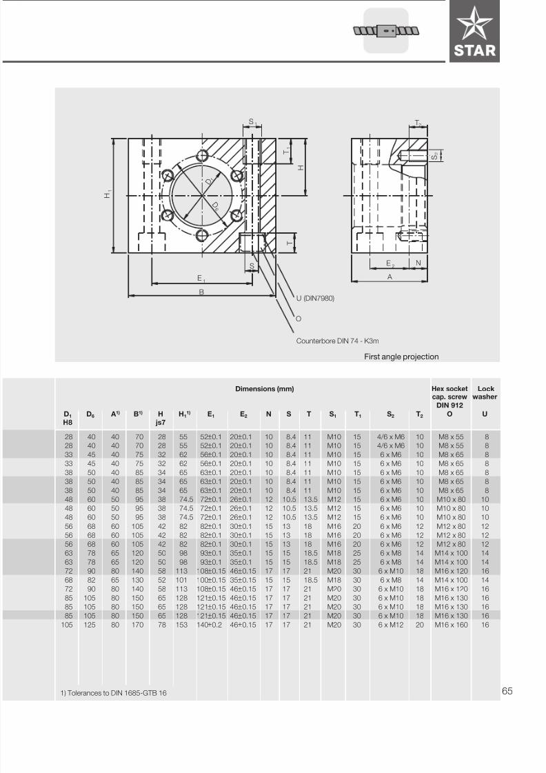
7/22/2019 Tornillo de Bolas BP-120
http://slidepdf.com/reader/full/tornillo-de-bolas-bp-120 65/68 65
Dimensions (mm) Hex socket Lockcap. screw washer
DIN 912D1 D6 A 1) B1) H H1
1) E1 E2 N S T S1 T1 S2 T2 O U
H8 js7
28 40 40 70 28 55 52±0.1 20±0.1 10 8.4 11 M10 15 4/6 x M6 10 M8 x 55 8
28 40 40 70 28 55 52±0.1 20±0.1 10 8.4 11 M10 15 4/6 x M6 10 M8 x 55 8
33 45 40 75 32 62 56±0.1 20±0.1 10 8.4 11 M10 15 6 x M6 10 M8 x 65 8
33 45 40 75 32 62 56±0.1 20±0.1 10 8.4 11 M10 15 6 x M6 10 M8 x 65 8
38 50 40 85 34 65 63±0.1 20±0.1 10 8.4 11 M10 15 6 x M6 10 M8 x 65 8
38 50 40 85 34 65 63±0.1 20±0.1 10 8.4 11 M10 15 6 x M6 10 M8 x 65 8
38 50 40 85 34 65 63±0.1 20±0.1 10 8.4 11 M10 15 6 x M6 10 M8 x 65 8
48 60 50 95 38 74.5 72±0.1 26±0.1 12 10.5 13.5 M12 15 6 x M6 10 M10 x 80 10
48 60 50 95 38 74.5 72±0.1 26±0.1 12 10.5 13.5 M12 15 6 x M6 10 M10 x 80 10
48 60 50 95 38 74.5 72±0.1 26±0.1 12 10.5 13.5 M12 15 6 x M6 10 M10 x 80 10
56 68 60 105 42 82 82±0.1 30±0.1 15 13 18 M16 20 6 x M6 12 M12 x 80 12
56 68 60 105 42 82 82±0.1 30±0.1 15 13 18 M16 20 6 x M6 12 M12 x 80 12
56 68 60 105 42 82 82±0.1 30±0.1 15 13 18 M16 20 6 x M6 12 M12 x 80 12
63 78 65 120 50 98 93±0.1 35±0.1 15 15 18.5 M18 25 6 x M8 14 M14 x 100 14
63 78 65 120 50 98 93±0.1 35±0.1 15 15 18.5 M18 25 6 x M8 14 M14 x 100 14
72 90 80 140 58 113 108±0.15 46±0.15 17 17 21 M20 30 6 x M10 18 M16 x 120 16
68 82 65 130 52 101 100±0.15 35±0.15 15 15 18.5 M18 30 6 x M8 14 M14 x 100 14
72 90 80 140 58 113 108±0.15 46±0.15 17 17 21 M20 30 6 x M10 18 M16 x 120 16
85 105 80 150 65 128 121±0.15 46±0.15 17 17 21 M20 30 6 x M10 18 M16 x 130 16
85 105 80 150 65 128 121±0.15 46±0.15 17 17 21 M20 30 6 x M10 18 M16 x 130 16
85 105 80 150 65 128 121±0.15 46±0.15 17 17 21 M20 30 6 x M10 18 M16 x 130 16
105 125 80 170 78 153 140±0.2 46±0.15 17 17 21 M20 30 6 x M12 20 M16 x 160 16
Counterbore DIN 74 - K3m
1) Tolerances to DIN 1685-GTB 16
S 1
T 1
H
T
H
1
B
E1
S
O
U (DIN7980)
T 2
E2
N
A
S 2
D 1
D 6
First angle projection

7/22/2019 Tornillo de Bolas BP-120
http://slidepdf.com/reader/full/tornillo-de-bolas-bp-120 66/6866
Star Linear Systems
14001 South Lakes Drive
Charlotte, NC 28273
Telephone 704-583-4338
Telefax 704-583-0523
STAR – Precision Ball Screw Assemblies
Design Calculation Form
Operating conditionsLoads [N] Speeds [rpm] Operating time [%]
F1 = at n1 = for q1 =
F2 = at n2 = for q2 =
F3 = at n3 = for q3 =
F4 = at n4 = for q4 =
F5 = at n5 = for q5 =
F6 = at n6 = for q6 =
Average load Average speed Total operating time
Fm = nm = Q = 100%
Sender OEM Anwender Händler
Company: __________________________________________ Name: __________________________________________
Address: __________________________________________ Department: __________________________________________
__________________________________________ Telephone: __________________________________________
__________________________________________ Telefax: __________________________________________
Application: New design Revised design
Maximum static load: N
Required service life ________________ Operating hours or _____________________________ x 106 ball screw revolutions
Screw end fixity
fixed fixed floating fixed
I II III IV
fixed floating floating free
Selected:
Installation conditions (enclose drawings/sketches if possible!) Drawing enclosed
Type of lubrication
Operating temperature: °C - min/max. / °C
Exceptional operating conditions:
Design Calculation Form
Total stroke length:

7/22/2019 Tornillo de Bolas BP-120
http://slidepdf.com/reader/full/tornillo-de-bolas-bp-120 67/68 67
STAR Screw
Nominal diameter ................................................................ d0 = _________ mm
Lead right-hand left-hand...................................... P =_________ mm
STAR Nut
FEM-E-C ZEM-E-A SEM-E-C FDM-E-C
FEM-E-S ZEM-E-S SEM-E-S FDM-E-S
with with
backlash preload
Mounting direction of nut:
Mounting ø D1 (or in the case of ZEM-E-A/S, lube port) facing drive end
facing non-drive end
STAR Screw
Tolerance grade P1 T1 ν300 p = 6 µm
(see Page 14/15) P3 T3 ν300 p = 12 µm
P5 T5 ν300 p = 23 µm
T7 ν300 p = 52 µm
T9 ν300 p = 130 µm
Total length ......................................................................... L = _______ mm
Threaded length .................................................................. L1 = _______ mm
Machining of screw ends........................ ends not machined
(Read bearing ends annealed LG1 / LG2 _____ / _____ mm
recommendations carefully!) to customer specs (drawing required)
to STAR specs (page 46/47)
Type of drive end.................................... for fixed bearing for floating bearing
Type of non-drive end............................. for fixed bearing for floating bearing
STAR End bearings ............ Part no./ Drive end 1 5 9 - -
............ Part no./ Non-drive end 1 5 9 - -
STAR Housings for flanged nut ................Part no. 1 5 0 6 - -
Star Linear Systems
14001 South Lakes Drive
Charlotte, NC 28273
Telephone 704-583-4338
Telefax 704-583-0523
Quantity Order for:____ units, _____ per month, ______ per year, per order, or ____________________
Comments:
Sender OEM Anwender Händler
Company: __________________________________________ Name: __________________________________________
Address: __________________________________________ Department: __________________________________________
__________________________________________ Telephone: __________________________________________
__________________________________________ Telefax: __________________________________________
Part number 1 5 - -
=
=
=
=
=
Inquiry / Order Form

7/22/2019 Tornillo de Bolas BP-120
http://slidepdf.com/reader/full/tornillo-de-bolas-bp-120 68/68
St ar Pro duct s Rexroth Star of fers a complete line of linear mot ion products...
Ball Rail® Systems
RA 82 201
Roller RailsTM
RA 82 301
Linear Bushings
RA 99 004
Precision Ball Screw A ssemblies
RA 83 301
Linear M odules
RA 82 401
Compact M odules
RA 82 600
Linear M otion Slides
RA 83 300
Ball Rail® Tables
RA 82 510
Super Structure™
RA 82 800
Special Systems
RA 99 003
Tychoway® Linear Roller Bearings
RA 99 001
Cam Roller Guide
RA 82 100