TOPOGRAPHY 2006 Revision - University of Wyoming · Small drainage reconstruction is discussed in...
19
TOPOGRAPHY Section Editor: Bob Stowe Handbook of Western Reclamation Techniques Second Edition
-
Upload
phungtuong -
Category
Documents
-
view
217 -
download
3
Transcript of TOPOGRAPHY 2006 Revision - University of Wyoming · Small drainage reconstruction is discussed in...

TOPOGRAPHY Section Editor: Bob Stowe Handbook of Western Reclamation Techniques Second Edition

i
Table of Contents Section 1: Topography ........................................................................................................................ 1
A. Introduction ................................................................................................................................. 1 B. Hills/Slopes ................................................................................................................................. 1
1. Hillslope Shaping and Morphology .......................................................................................... 1 Applicability ............................................................................................................................... 1 Special Considerations ............................................................................................................. 1 Techniques ................................................................................................................................ 2
a. Hillslope ........................................................................................................................ 2 (1) Hilltop or Interfluve .................................................................................................... 3 (2) Hillslope: Shoulder and Arm of Slope ....................................................................... 3 (3) Hillslope: Toe of Slope .............................................................................................. 8
Figure B-1-4 ......................................................................................................................... 10 b. Summary of Hillslope Morphology .............................................................................. 10 c. Construction Practices ............................................................................................... 10
C. Backfill Grading Observations .................................................................................................. 11 Applicability ............................................................................................................................. 11 Special Considerations ........................................................................................................... 11 Techniques .............................................................................................................................. 11
a. Dump Slope Grading .............................................................................................. 11 b. Second Bench ............................................................................................................ 12 c. Dump Top Reclamation .............................................................................................. 12 d. Long Slope Grading ................................................................................................... 13
D. Evaluation and Comparison of Topographic Descriptive Methods ........................................... 13 Applicability ............................................................................................................................. 13 Special Considerations ........................................................................................................... 13 Techniques .............................................................................................................................. 13
a. Evaluation and Comparison of Topography Techniques ............................................ 13 (1) Elevations ............................................................................................................... 14 (2) Isopleth Map ........................................................................................................... 15 (3) Mapping Geomorphic Features .............................................................................. 15
D. References ............................................................................................................................... 17
Section1: Topography Page1-1 Handbook of Western Reclamation Techniques Second Edition
Section 1: Topography
A. INTRODUCTION Section editor: Robert R. Stowe
Reclamation of western lands can be enhanced with some forethought about how the reclaimed topography will look and how it will function with the proposed postmining land use. When land is being reclaimed from surface mining or other surface disturbance back into grazing land and/or wildlife use, adding some macro- and micro-relief structures can be of benefit to both livestock and wildlife. Semi-arid conditions frequently mean few or no trees and strong winds. When there is little or no topographic relief to protect livestock and wildlife from the summer sun and the winter winds, animals suffer and may perish. Topographic relief can provide the protection required in addition to augmenting the postmining land use.
In areas where reclaimed lands will become farm land, topographic design is also important. In these situations, minor hills and slopes, as well as drainages, should be designed so that runoff from precipitation and snowmelt will not inundate land to be farmed, and the reconstructed drainage-ways will not be overly erosive.
The following subsections discuss methods of shaping hillslopes in order to provide topographic diversity for wildlife and livestock while minimizing erosion. A discussion of procedures used to compare the pre-mining and postmining slope regime is also included.
B. HILLS/SLOPES 1. Hillslope Shaping and Morphology
Section editor: Robert R. Stowe Subsection authors: Christopher D. Lidstone/C. Marty Jones
Applicability Landform stability is a critical element in the reclamation of mined lands. The hillslope is the uppermost unit of the basin watershed and is typically responsible for the production of sediment to the watershed. Concentrated flow or flowing water transfers this sediment to the first and second order stream channels and ultimately delivers the sediment to receiving waters outside the mine permit area. Where surface runoff remains unconcentrated, little sediment movement and virtually no transfer of sediment off-site will occur.
The intent of mining regulations is to minimize off-site production of sediment and to reestablish a hydrologic system that will behave in an erosionally stable manner equal to or better than that which existed prior to mining.
The hillslope component of reclaimed basins is the upper watershed and valley sideslopes that deliver runoff to the smallest (first order) designed drainages in the reclamation plan. Where slope gradients or slope length exceed some threshold value, surface water runoff will concentrate, producing rill and gully erosion. Hillslope shaping, and an understanding of slope morphology and processes, will reduce surface erosion on reclaimed hillslopes.
Special Considerations Decisions regarding landform shaping must balance mine planning, mining methods, geomorphic processes, and economics. The operator must consider the locations and elevations of haulage roads, ramps, spoil piles, pre-existing and postmining basin outfalls and drainage divides.

Section1: Topography Page1-2 Handbook of Western Reclamation Techniques Second Edition
For example, mine production features such as haulage ramps and roads can often become components of the postmining drainage system. In these areas, backfill costs can be reduced if postmining drainages are restored to incorporate a portion of the ramp or road alignment.
Similarly, out-of-pit overburden stockpiles and/or dragline spoil dumps can be formed into the upper elevation or hillslope component of the drainage system. In doing this, the operator can minimize "double handling" and reduce hauling costs. Pit backfill sequencing should incorporate the final reclamation topography and address not only final drainage design but also final hillslope design.
The overall reclamation plan and hillslope design must reflect such critical variables as postmining basin outfalls and the topography of adjacent lands. Reclamation planning should consider basin or hillslope aspect. Final topography can be adjusted to accommodate the harsher conditions associated with aspect and slope, which influence solar and wind exposure. Experience suggests that there is a significant improvement in reclamation success on protected slopes. Increased moisture retention is required on southern exposure slopes. This can be accomplished by flatter slope angles and a more roughened final reclamation surface.
Techniques a. Hillslope
The hillslope is defined by a minimum of four subunits and is described with standard nomenclature (after Perrens, et.al. 1984) as shown on the adjacent figure. These particular units were first developed by agronomists in recognition of the importance of position on a natural hillslope with respect to soil genesis. Soils that develop near the shoulder and arm of the slope are transported by both water and gravity to the toe of the slope. In nature, soil horizons are thickest at the toe of the slope and thinnest at the shoulder.
When replacing topsoil on a reclaimed hillslope, it is typically replaced to a uniform depth. As natural erosion and deposition occur on the reclaimed hillslope, translocation of topsoil will take place and over time the thicker zones will occur at the toe of the slope. Recognizing that these processes will occur, yet designing the slope to minimize the movement of topsoil by accelerated processes such as rill and gully erosion, is a critical design consideration.
Hillsope should recognize the value of rainfall infiltration and the liability of direct surface runoff. Water retention on the hillslope will promote revegetation success, and by so doing will stabilize the reclaimed land surface. Where runoff occurs in a concentrated

Section1: Topography Page1-3 Handbook of Western Reclamation Techniques Second Edition
manner, excessive shear forces may occur, resulting in rill and gully erosion. Minimizing slope length and excessive slope gradients will prevent the concentration of direct surface runoff on the hillslope.
(1) Hilltop or Interfluve As a rule of thumb, the acreage of the hilltop should be maximized and the overall slope length minimized. The hilltop should be formed to retain the maximum moisture onsite with minimum delivery of runoff from the hillslope. In the field, this translates as grade staking the top of an overburden stockpile or dragline dump to ensure the flattest possible configuration (20H:1V or flatter) while maintaining an overall positive drainage. Leaving the regraded surface in a roughened condition will enhance its water retention capabilities.
Immediately prior to the replacement of topsoil, the overburden should be "deep-ripped" or scarified. The topsoil can be replaced directly on the rough overburden backfill surface (at variable thicknesses) and/or the replaced topsoil can be manipulated by mechanical farming methods. Reclamation success has been achieved with "pitting", which is a mechanical means of constructing actual soil pits or divots within the topsoiled surface. Pitting is accomplished simultaneously with drill seeding during final reclamation. Similarly, the construction of small intermittent dozer basins has successfully achieved water retention goals and aided in the development of small playa-like features.
Where a greater acreage of interior drainage is required or desired, the replacement of well-drained soils is essential to prevent the unwanted accumulation of salts. Although natural playas and interior drainage features exhibit predominantly clay soils, the elimination of salt accumulation will enhance revegetation efforts during the critical initial years of bond release.
A final consideration in the geometry of the hilltop is an assessment of the basin area contributing to the receiving drainages. Basin divides can be manipulated to increase the watershed area and peak flow hydrology of one basin while decreasing the watershed area and peak flow hydrology of an adjacent basin. If channel slopes are excessive in one basin, part of the basin runoff can be diverted to another basin, thereby decreasing the overall peak flow hydrology of that basin.
(2) Hillslope: Shoulder and Arm of Slope To the extent possible, slope length and the slope steepness should be controlled to eliminate excessive erosion. Initial slopes on mine dumps typically range from angle of repose to 1.5H:1V. Minimum reclamation slopes are often controlled by equipment accessibility and the ability to "farm along the contour". Although minimum "farmable slopes" may range from 2.5H:1V to 3H:1V and are dependent on the farming equipment, revegetation is often most successful on 4H:1V or shallower slopes.
Section1: Topography Page1-4 Handbook of Western Reclamation Techniques Second Edition
In arid and semi-arid climates, slope aspect plays an important part in vegetation success; 5H:1V or flatter minimums are found to be successful on south aspect slopes. North-facing slopes can be slightly steepened and 4H:1V minimums have proven to be successful. Wherever possible, flatter slope gradients are highly recommended and will increase rainfall infiltration and decrease concentrated flow. Such uniformity of terrain enhances vegetation cover and production but may reduce vegetation diversity and will certainly decrease wildlife diversity and cover for livestock during adverse weather conditions.
Slope length and slope shape are also critical design considerations. The slope shape and slope transitions should be designed to promote unconcentrated flow and to minimize the offslope delivery of sediment. Where the combination of critical slope characteristics (slope length, slope steepness and contributing area) will result in concentrated flow, runoff and sediment should be collected into a first-order channel and be delivered in a controlled manner offslope. Small drainage reconstruction is discussed in the Hydrology section of this handbook.
Practical experience has shown that slope lengths in excess of 50 to 100 feet at gradients of 4H:1V or steeper may result in rill and gully erosion. At 5H:1V slopes, lengths in excess of 150 feet or more may be erosive. Of course, vegetation density, soil type, and storm intensity and distribution are important variables in this analysis. Coarse textured soils and/or successfully vegetated slopes allow more latitude in slope length than do fine-textured, poorly vegetation hillslopes.
Cross-slope ditches or furrows can be incorporated into hillslope reclamation to achieve the required slope lengths. Such ditches should be small and unobtrusive and should be constructed oblique to the contour.
In order to reduce the probability of ditch failure, a minimum gradient of four percent should be established for all cross-slope ditches. Flatter ditch slopes and contour ditches are difficult to construct, and tend to collect water in low spots created by settlement of the fill or poor staking/construction practices. These low areas do provide micro-habitat that leads to vegetation and terrain diversity.
Figures B-1-2 presents typical hillslope shapes and a mass balance of erosion and deposition along the hillslope. The movement of sediment within the hillslope component is a function of both water and gravity. From a practical standpoint, uniform and concave slopes are most often employed in mined land reclamation. Of these two slopes, the concave slope provides a more stable land surface as seen in Figure B-1-2.\
Complex slopes are the most common found in nature. These slopes exhibit increased erosion along the center or medial portion of the slope and increased deposition at the toe of the slope. If designed properly, a complex

Section1: Topography Page1-5 Handbook of Western Reclamation Techniques Second Edition
slope can be a stable entity within the overall reclamation scheme and provide diversity in the overall reclamation topography.

Section1: Topography Page1-6 Handbook of Western Reclamation Techniques Second Edition
Figure B-1-2

Section1: Topography Page1-7 Handbook of Western Reclamation Techniques Second Edition
Uniform slopes are the easiest to stake and construct in the field. The slope configuration provides few depositional sites within the hillslope. However, where excessive slope lengths occur, offslope transport of sediment (erosion) can be anticipated. Where uniform slopes are staked in the field, flatter gradients and adequate transitions at the toe must be incorporated. Figure B-1-3
Figure B-1-3

Section1: Topography Page1-8 Handbook of Western Reclamation Techniques Second Edition
presents a 4H:1V uniform slope. Depending on slope length, basin aspect, and transition requirements, a flatter slope such as a 5H:1V or 6H:1V may be recommended.
Concave slopes may require additional staking and construction supervision, but provide better control of sediment movement and a more stable land surface (Figure B-1-3). The lower gradient portion of the slope allows water velocities to decrease, thereby enhancing deposition. The increased staking and construction supervision responsibilities required to construct concave slopes may offset long term maintenance responsibilities.
A variation of the concave slope might entail a 4H:1V slope from the interfluve to the arm of the slope and a 5H:1V slope from the arm through the toe section of the slope. Practically speaking, in a multiple-benched mine dump, the upper lifts would be graded to a 4H:1V slope. The cut material would be relocated to the base of the dump and the 5H:1V toe slope would be created (Figure B-1-3). The point of inflection between the 4H:1V and 5H:1V slope (intermediate catch point) would be established based on an earthwork balance.
Complex slopes require intermediate cut stakes as well as the staking of each catch point (Figure B-1-3). Typically the construction of a complex slope may require additional earthwork, although there will be certain earthwork savings in the steep upper "shoulder" reach. The upper reaches of a complex slope provide maximum surface area for rainfall infiltration and minimum runoff. The arm of the slope is the steepest portion of the slope, yet will have limited drainage area contributing to direct surface runoff. Where runoff does occur, the hillslope gradients are the most gentle and velocities will be reduced.
(3) Hillslope: Toe of Slope The construction of the toe of the slope is often the most essential aspect in hillslope reclamation. Too often the toe of the slope will be left in a convex or over-steepened form. This condition will often result in erosion, since the hillslope drainage basin area is the greatest at the toe of the slope. Because runoff increases with increased drainage area (Figure B-1-4), it is essential that the slope gradient decreases at the toe of the slope. The design intent is to maintain unconcentrated flow and promote infiltration. The lower gradients will also promote the deposition of hillslope sediment, thereby reducing sediment contribution to receiving drainages.
A second element in the construction of the toe of the slope is the smooth transition of the hillslope into the adjacent reclamation valley. A low gradient toe, which transitions into a stream valley, will allow lateral movement of a reclamation channel against the hillslope. If the slope enters the stream valley in an over-steepened condition, erosion and undercutting of the toe is likely to occur.

Section1: Topography Page1-9 Handbook of Western Reclamation Techniques Second Edition

Section1: Topography Page1-10 Handbook of Western Reclamation Techniques Second Edition
Figure B-1-4 b. Summary of Hillslope Morphology
Hillslope design should maximize the opportunity for rainfall infiltration and minimize the opportunity for surface water runoff and flow concentration. The movement of sediment within the hillslope form is an essential geomorphic element in natural slope processes. Minimizing offslope movement via rill and gully erosion is critical, and will result in a reduction in sediment contribution to the receiving drainages.
Figure B-1-3 presents the three slope shapes discussed above and the minimum construction staking requirements. Although all three slope shapes are presented, the concave slope design best balances the economics of material movement with the design philosophy discussed above.
c. Construction Practices Construction requirements are relatively simple and much work can be completed with a dozer. If dozers are used in construction, catch points should be staked in the field and adequate compaction be required near the toe. If scrapers are used in construction, additional staking to define cuts may be helpful.

Section1: Topography Page1-11 Handbook of Western Reclamation Techniques Second Edition
Some compaction of the fill portion of the hillslope is essential to prevent or eliminate settlement, and in some cases failure of the fill. Concern with compaction is not as pronounced when construction by scrapers is employed. When backsloping a fill against a highwall, the fill must be keyed. In certain instances where ground water is encountered, drainage below the fill must also be incorporated into the design.
C. BACKFILL GRADING OBSERVATIONS Section editor: Robert R. Stowe Subsection author: Frank K. Ferris
Applicability Relief techniques are an important tool in controlling erosion and cost. Planning a watercourse for drainage will facilitate preparation for the flow and reduce erosion on reclaimed lands. Costs can be controlled by planning for the placement of backfill and having the backfill dumped to grade as much as possible. The incremental haulage or handling cost of $ 0.05 per yard is very economical compared to the $ 0.25 to $ 0.50 (1996 dollars) per yard cost of rehandling backfill.
Special Considerations Backfill will settle differentially, up to ten feet on a rare occasion; three feet is not unusual. Constructed topographic features must be massive enough to function even with settling in critical areas. Plan ahead to know your desired topography. This will allow for maximum use of mine equipment for placing and grading backfill while that equipment is in the area. Finish grading of frozen backfill will likely take two to three times the equipment hours as compared to thawed backfill.
Techniques a. Dump Slope Grading
Dump grading can be made more economical by the selective placement of loose dumps and through dump grade control (Figure C-1). Dump grading volume can be reduced and maintained with several methods. Figure C-1

Section1: Topography Page1-12 Handbook of Western Reclamation Techniques Second Edition
(1) Decreasing the dump height by five to seven feet (loose dump height). (2) Sloping the dump grade to be lower at edges and high where needed. (3) Placing loose dumps at the toe area, dump top, and ridge spots to reduce dozing needs and create micro-features and drainage control.
b. Second Bench A second bench reduces reclamation grading volume by 70 percent (see Figure C-2). In this example, the volume was reduced from 48 yards3 to 14 yards3 per linear foot of dump face with a 50 percent reduction in push length. Figure C-2
The second bench can be built between or after the main dump. However, if it is built first, it will reduce the overall cycle time of the haul trucks because they will not have to climb to the top to dump all loads of dirt. After the lower dump is in place, the toe limits of the second (top) dump can be established on the second bench. This construction methods will required additional dump dozer activity during backfilling.
c. Dump Top Reclamation "Small Drainage Waterway Construction" in the Hydrology section of this handbook can be reviewed for dump top reclamation. It is extremely important to limit the flat areas above slopes because concentrations of runoff down the slope will cause slope erosion. Generally there are two options, depending upon the width of the dump:

Section1: Topography Page1-13 Handbook of Western Reclamation Techniques Second Edition
(1) Grade to a hill with interior drainage (Figure C-3) (2) Grade to a hill Figure C-3
d. Long Slope Grading For information on Long Slope Grading, review "Small Drainage Waterway Construction"
in the Hydrology section of this handbook.
D. EVALUATION AND COMPARISON OF TOPOGRAPHIC DESCRIPTIVE METHODS Section editor: Robert R. Stowe Subsection author: Robert R. Stowe
Applicability Reclamation of mined lands and other major surface disturbance requires a comparison between premining and postmining slopes. This comparison ensures that the postmining topography will support the desired postmining land use. Reconstructed land must blend with native land and postmining slopes must be neither much steeper nor much flatter than original slopes.
Special Considerations Slope comparisons generally divide the land surface into a number of grid cells in order to calculate the slope, or rise divided by run, at the grid cell node. This information can then be mapped in several ways. Three methods for evaluating and comparing topography techniques are outlined below.
Techniques a. Evaluation and Comparison of Topography Techniques

Section1: Topography Page1-14 Handbook of Western Reclamation Techniques Second Edition
From any of the following three techniques, tables and histograms can be generated to evaluate the percentage of topographic surface with certain slopes or features. Tables and histograms are especially useful when comparing two surfaces, for example, premining and postmining topography. Many engineering firms are available to conduct these evaluations. Special engineering software packages are also available to make these calculations and comparisons.
(1) Elevations Slope value and optionally, slope direction, which yields a vector, must first be plotted for each grid node. The nodes for the grid and search radius should be selected so that averaging or smoothing between nodes conceals variability in the underlying topography. In one particular form of this method, slopes are calculated by first estimating elevation values into a 100-foot grid from irregular contour data. These grid values are then subtracted from the nearest neighbor to provide a change
in elevation in each cardinal direction.
Elevation differences in north and south directions are added, then divided by the total difference between grid values (i.e. 200 feet), to provide a slope in the north-south direction. The same is done for the east-west direction. These component slopes are then added, via vector analysis, to yield the slope magnitude in percent and direction in degrees at the node being analyzed. Vectors may be drawn from each node pointing downslope, with the length of the vector denoting the steepness of the slope.
The above analysis is typically performed every 300 feet to separate posted data values sufficiently for plotting purposes (postmining values at 100-foot spacing would require a very large map with no gain in accuracy or precision).
Slope isopleths may be drawn by contouring the slope magnitude from the slope data on 300-foot centers. Slopes are calculated within projected disturbance limits only, and both pre- and post-mining slopes are calculated
Section1: Topography Page1-15 Handbook of Western Reclamation Techniques Second Edition
on identical 300-foot centers to allow direct comparisons. These values are then posted on a screened topographic base map (Figure D-1). This dynamic map can provide insights about potentially erosive areas and where deposition is likely to occur in a drainage
(2) Isopleth Map A second method is to contour the points of equal slope in an isopleth map. The contours on this map show the areas of increasing or decreasing slope. A plain with little relief would show few isoslope contours, whereas a quickly steepening bluff would be depicted by many isoslope contours. Water will flow perpendicular to the isoslope contour lines. This is illustrated in Figure D-2.
(3) Mapping Geomorphic Features
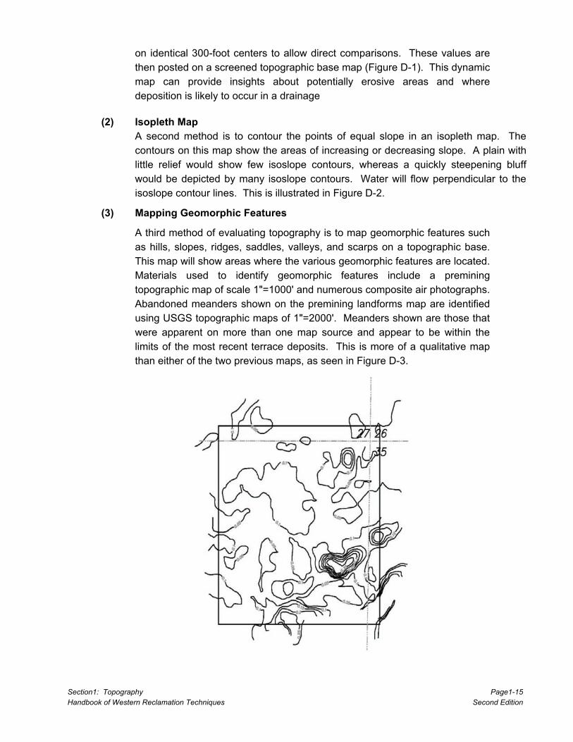
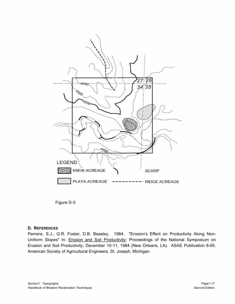
A third method of evaluating topography is to map geomorphic features such as hills, slopes, ridges, saddles, valleys, and scarps on a topographic base. This map will show areas where the various geomorphic features are located. Materials used to identify geomorphic features include a premining topographic map of scale 1"=1000' and numerous composite air photographs. Abandoned meanders shown on the premining landforms map are identified using USGS topographic maps of 1"=2000'. Meanders shown are those that were apparent on more than one map source and appear to be within the limits of the most recent terrace deposits. This is more of a qualitative map than either of the two previous maps, as seen in Figure D-3.

Section1: Topography Page1-16 Handbook of Western Reclamation Techniques Second Edition
Figure D-2
Section1: Topography Page1-17 Handbook of Western Reclamation Techniques Second Edition
Figure D-3
D. REFERENCES Perrens, S.J., G.R. Foster, D.B. Beasley. 1984. "Erosion's Effect on Productivity Along Non-Uniform Slopes" In: Erosion and Soil Productivity; Proceedings of the National Symposium on Erosion and Soil Productivity; December 10-11, 1984 (New Orleans, LA). ASAE Publication 8-85. American Society of Agricultural Engineers, St. Joseph, Michigan.