Topographical & Bathymetric Surveying - Orbital Africa · we have on the project has enabled us to...
16
PROCEDURE MANUAL TOPOGRAPHICAL AND BATHYMETRIC SURVEYS Presented By: ORBITAL AFRICA LTD. We MAP. You Explore!
Transcript of Topographical & Bathymetric Surveying - Orbital Africa · we have on the project has enabled us to...

Procedure Manual: Topographical and Bathymetric Survey Services
PROCEDURE MANUAL
TOPOGRAPHICAL AND BATHYMETRIC SURVEYS
Presented By:
ORBITAL AFRICA LTD.
We MAP. You Explore!

Procedure Manual: Topographical and Bathymetric Survey Services
2
Table of Contents
1. ABOUT ORBITAL AFRICA ........................................................................................ 3
2. TECHINICAL PROPOSAL .......................................................................................... 4
3. TOPOGRAPHICAL SURVEY ...................................................................................... 5
4. BATHYMETRIC SURVEY ........................................................................................... 6
5. METHODOLOGY..................................................................................................... 8
6. LIST OF SOFTWARE ............................................................................................... 13
7. SURVEY EQUIPMENT ............................................................................................ 14
8. SAMPLE DELIVERABLES .......................................................................................... 15
9. PROPOSED WORK PLAN ....................................................................................... 16
Procedure Manual: Topographical and Bathymetric Survey Services
3
1. ABOUT ORBITAL AFRICA
Orbital Africa is a registered company under the laws of Kenya.
Orbital is a Geographic Information System (GIS), ICT, Remote
Sensing (RS) and spatial planning consulting firm helping to deliver
geospatial solutions that enable our clients to become high-
performance businesses.
Orbital Africa is offers survey and mapping consulting services in
Kenya and Eastern Africa at large with more than 8 years of proven
track record in delivery of robust geoinformation services including
land and topographical surveying, mobile and web mapping, spatial
planning, land-use and urban planning including Geospatial training
services here in eastern Africa region.
Established in the year 2008, Orbital Africa was incorporated in 2nd
August 2011 and began
operations thereafter. By providing outstanding client-tailored Geospatial services, we ensure
customer satisfaction at all stages of project planning and execution.
Orbital Africa offers an array of Geospatial services in the following areas: topographical and land
surveying services; GIS and mapping services; web mapping application development; 3D
mapping; map production services; enterprise GIS solutions; project planning and management;
GIS data capture; urban/spatial planning, Geoinformation training and capacity development;
sales and support and technical support services.
Orbital Africa has undertaken several GIS, mapping and engineering design projects to a wide
range of clients in Kenya, Uganda and Tanzania, and has a proven track record in areas of capacity
building and systems development.
Orbital Africa is differentiated in the marketplace by consistency in building
long-term, trust-based relationships with clients; focusing on value creation
and business outcomes; fostering a culture of innovation, collaboration and
teaming, leveraging on our delivery networks and project management for
quality, speed and cost effectiveness; attracting, developing and retaining the
best talent.
Orbital Africa is led by a diverse management team with a broad base of
business and technical industry experience in Geospatial service delivery. Our
management team provides strategic and operational direction to the staff
members of the company thus fostering competency in service delivery and
execution of big projects.

Procedure Manual: Topographical and Bathymetric Survey Services
4
2. TECHINICAL PROPOSAL
3.1 Background
Fiveght contacted Orbital Africa to provide a detailed technical and financial proposal for carrying
out Topographical and Bathymetric Survey along R. Tana in Kitui County. The Terms of Reference
(ToR) and scope for this consultancy were found to be fairly well written and clearly reflects the
Fiveght intention in accomplishing the task efficiently and expeditiously. The in-depth information
we have on the project has enabled us to prepare a technical proposal that will afford the client
optimum service at an affordable cost.
3.2 Objectives
❖ To establish Ground control Points (GCPs) on project area;
❖ To carry out detailed topographical survey;
❖ To conduct detailed bathymetric survey
❖ To generate longitudinal and cross-section profiles of the river channel;
❖ To produce topographical and contour maps
3.3 Location of Project Area
The project area is located along R. Tana near Usueni in Kitui County. The coordinates of the
project area are 0° 9'15.81"S, 38°11'36.30"E. The figure below depicts the location of the project
area.
Fig 1: Location of Project Area
3.4 Project Reconnaissance
Before the execution of the project, the site pre-visit is of paramount importance as it allows our
team of Surveyors get acquainted with the nature of site, terrain, whether bush clearing is needed
among other tasks. The details obtained will be used among other things to approximate the
project duration, amount of resources that need to be mobilized and other logistical arrangement
prior to commencement of the project.

Procedure Manual: Topographical and Bathymetric Survey Services
5
3. TOPOGRAPHICAL SURVEY
4.1 Introduction
The aim of any topographical survey exercise is to determine the relative locations of points
(places) on the earth's surface by measuring horizontal distances (x and y), differences in elevation
(z) and directions (θ). The topographical maps that are produced often give the locations of places
(observable features within the study area) and information about changes in elevation depicted
using contours and spot heights. The topographical and cadastral maps also serve as base maps.
Plate 1: Topographical Survey and Field Data Collection
4.2 General Approach
The general approach is based on the objectives and scope of works. Basically, it consists of office
work, field data collection and map production works. The reconnaissance field visit is very
important to set out the proposed control points and decide on the number of benchmarks
required for complete topographical map preparation. The GPS crew establishes the control points
based on available National Grid Points and makes ready for further topographic data collection.
The topographic survey crews collect all necessary data points
and encodes them into the project database. The coded points
are later imported into AutoCAD Civil 3D for plotting,
contouring, profile generation and topographical map
production. There is daily communication and follow-up by the
data processing and map preparation/production team in
ensuring seamless workflow in data transmission from field to
office for quality control/quality assurance as well as processing.
The feedbacks and field verification of the processed contour map are done to check whether the
client’s requirements are adequately met. Thus, considering the above aspects of the approach, our
strategy in planning the feasibility, topographic and bathymetric survey works have been described
in detail in the subsequent sections.

Procedure Manual: Topographical and Bathymetric Survey Services
6
4.2.1 Requirements for Topo Survey
❖ The selection of a Scale to adopt in advance (depends on extent of project area); this
determines the plotable error.
❖ Our principle is to work from the most accurate to least accurate methods with minimal errors.
❖ The orientation of each survey must be and preferably with respect to the True North (N).
❖ The first stage of surveying exercise is will entail establishing both horizontal controls
(traversing) and vertical controls (levelling): the distance, direction and difference in elevation
between key fixed points. The control points (known points) shall be used as benchmarks for
the survey work.
❖ Once the horizontal and vertical control points have been established, readings are made from
a total station or geodetic GPS (RTK) placed on the known points. The readings on features
within the project area (e.g. edge of road, fence, corner of building, tree etc) are picked in 3D
format i.e. X, Y and Z.
❖ Lastly, we shall obtain a survey plan from lands office that will help us to check on the
accuracy, e.g. redundant points, pacing of measured distances, surveying between fixed
positions, etc.
❖ The collected field data is downloaded, and error checking is done before plotting and
drawing the features in AutoCAD Civil 3D.
4.2.2 Project Datasets
The topographical survey data shall be obtained directly from the field using modern survey
equipment. The secondary data such as survey plans shall be purchased from lands office.
i. Primary Data e.g. Ground Control Points, Spot heights, topo features data (X, Y and Z).
ii. Secondary Data e.g. Survey Plans, Topo maps of Scale 1:50,000, previous site plan, cadastral
maps etc.
4. BATHYMETRIC SURVEY
5.1 Introduction
Bathymetric (Hydrographic) Survey is the survey of physical features present underwater. It is the
science of measuring all factors beneath water that affect all the marine activities like dredging,
marine constructions, offshore drilling etc. Bathymetry is performed to map the under-water
bottom with a high level of accuracy. It will help correlation and interpretation of the data
obtained from other methods, which yield sub-bottom information and allow a quality check of
the results.
The principle of the method is to send an acoustic signal and measure the travel time to derive a
depth. This depth conversion process is done by first measuring the velocity of sound in the water
at different depths. This calibration is done twice a day to ensure a good accuracy. The water
depth measurements can be expected to be accurate to within ±10 cm. The bathymetry
equipment is a small equipment which is mounted on a boat and survey conducted along with
other geo-physical methods. Survey is conducted in a grid pattern. The line spacing is decided

Procedure Manual: Topographical and Bathymetric Survey Services
7
based on the resolution required. The accurate positioning is achieved using a Differential Global
Positioning System.
Plate 2: Bathymetric Survey and a Digital Elevation Map
The bathymetric survey works will be carried out over and along the river in question to
determine its depth at various sections and the terrain of its floor surface. Thereafter, detailed
bathymetric surveying work with the average cross-section at every 20m shall be carried out for
preparation of the recent Area–Capacity–Elevation Curve of the river at above predefined
intervals. A boat will be used to carry the measuring instrument and take depth as well as co-
ordinate data at designed locations.
5.2. Bathymetric Survey Methods
❖ Multi-beam surveying: A multibeam echo sounder attached to a boat sends out a wide array
of beams across a "swath" of the waterbody floor. As the beams are bounced back from the
waterbody floor, the data is collected and processed. The processed data can be viewed in
real time on the boat during the survey. Multi-beam surveying is generally done in larger
water bodies.
❖ Single-beam surveying: Rather than sending out a wide set of beams, single-beam bathymetry
measures the water depth directly under the boat. Single-beam surveys are generally used for
smaller water bodies.
❖ Acoustic Doppler Current Profiler (ADCP): ADCPs are used throughout USGS to measure
streamflow. ADCPs measure water velocity by transmitting sound waves which are reflected
off sediment and other materials in the water. Data collected from ADCPs can then be used to
for bathymetric mapping.
❖ Sub-bottom Profilers: Sub-bottom profilers are most commonly used to view the layers of
sediment and rocks under the water body floor. A transducer sends a sound wave to the
water body floor. This sound wave can penetrate the water body floor. The data returned
from the sound waves can be mapped to show the layers beneath the water body floor.
❖ Ecomapper Autonomous Underwater Vehicle: The Ecomapper can collect detailed
bathymetric data, down to one-foot contours, in places that are difficult to reach with boats.
The Ecomapper uses side-scan sonar and a Doppler velocity log.

Procedure Manual: Topographical and Bathymetric Survey Services
8
5. METHODOLOGY
6.1 TOPOGRAPHICAL SURVEY
6.1.1 Introduction
The proposed methodology will focus on primary (field) and secondary data collection and
management including data editing, cartographic map production and quality assurance and
control.
Fig 2: Topo Survey Methodology
6.1.2 Project Planning
The main output of this phase is the project plan and its associated plans for the functional areas of
scope, project schedule/timeframe, cost, quality control and assurance, human resources, change
management, communications, risks and mitigations, and procurement of products, services as
well as resources that need to be acquired for successful implementation of the project.
6.1.3 Site Pre-visit
Before the execution of the project, the site pre-visit is of paramount importance as it will allow
our team of surveyors get acquainted with the nature of site, terrain, planning on logistics,
whether bush clearing is needed etc. The details obtained will be used to approximate the project
duration, amount of resources (finance, time and personnel etc.) that need to be mobilized and
other logistical arrangement prior to commencement of the project.
Project Planning &
Mobilization of Resources
Data Collection Primary Data (levelling
and Traversing
Secondary Data e.g.
Survey Plans
Field Work
Data Preparation
Establishment of Ground
Control Points
Quality Control & Survey
Errors Adjustment
Map & Kapa Plan
Production & Reporting
Project handover and
Sign-off
Data
OK?
YES
NO
Creation of Feature Layers
in AutoCAD Civil 3D
Reconnaissance

Procedure Manual: Topographical and Bathymetric Survey Services
9
6.1.4 Horizontal Ground Controls
The method that we shall employ to establish the horizontal controls is closed traverse where
readings begin and end at fixed control points of known location. This permits the checking,
calculation and adjustment for closure error obtained during the readings from the total station.
6.1.5 Vertical Ground Controls
The aim of obtaining vertical distances is to determine the differences and changes in elevation
from one location to another. This task will be done using levelling method with a
digital/automatic level machine and a levelling staff.
6.1.6 Proposed Topo Features/Data
❖ Edges of the Rivers;
❖ Roads/Foot paths;
❖ Spot heights;
❖ Trees and bushes;
❖ Wetland Areas;
❖ Building Structures;
❖ Utilities onsite e.g. electricity line & poles etc.
6.1.7 Topo Survey Process
A general topographic map shall be prepared at a scale not more than 1:1,000 showing ground
features (drainage line, rivers, water points, settlements, foot path, gullies, trees, bench marks, hills,
flood plain, wetland, catchment, spot heights etc.) and levels at a contour interval of 1.0 meter on
flat terrain and at 0.5m contour interval in undulating and steep terrain. The specific major
topographical and drainage structures on the project area shall be mapped at 1:500 scales with
0.5-meter contour interval to enable typical layout preparation during preliminary planning and
detail design stage.
The topographic maps of the river channel will be prepared at scale of 1:1,000, 1:500 or at
appropriate scale depending on the client’s specification. The contours are generated at a contour
interval of 0.5m. We believe that using a topo-map with this proposed scales and contour interval
at 0.5m has an advantage to have representative and detailed survey data. The topographic
survey and map to be produced covers the river basin area which is inundated during seasonal
flooding. The topographic survey will indicate the configuration of the terrain and location of
both natural and manmade objects, if any, from the known benchmarks.
The topographic detail maps of the site shall be compiled at a target scale of not less than 1:1,000
for the general area. The mapping and related digital product shall meet or exceed ASPRS
(American Society of Photogrammetry & Remote Sensing) Horizontal Accuracy at 95%
Confidence Level accuracy standards (RMS error in X coordinate limited to 15 mm). Appropriate
instrumentation and procedures, consistent with accepted professional surveying and mapping
industry standards and practice, shall be selected to achieve the accuracy required.
Procedure Manual: Topographical and Bathymetric Survey Services
10
The topographic survey of the project area shall provide basic water surface level and bed levels.
Further, detail topographic survey will be conducted upstream and downstream to indicate the
surrounding topographic conditions and produce a detailed topo-map. The surveying work shall
entail ground surveying comprising of ground control points establishment using Fixed GPS and
data collection using total station and digital level machines.
A fully equipped survey crew consisting of professional survey personnel, experienced in
performing the required surveys and capable of completing the work within the allotted time
frame (e.g. 10 days) executes the project. All field observation data required to set and establish
project control shall be digitally recorded. The use of GPS referenced drones shall also be
employed if we deem it fit. All survey work shall be performed under adequate supervision and
quality control measures. The deficiencies shall be recognized and steps to initiate corrective
actions shall be taken as required.
The maps shall contain all the topographic and planimetric features encountered. The maps will
properly depict the existing site conditions as necessary. The final mapping products shall comply
with and contain but not be limited to the following:
❖ All terrain features including contours of the riverbed, upstream and downstream;
❖ The turning points that define drainage channels, ditches, etc., will be consistent in depicting
correct alignment and direction of drainage if available;
❖ Spot elevations shall be established and shown on the maps at selected points, such as hill
tops, depressions, at intersections and along centrelines of streets and bridges;
❖ Surface and sub-surface utility systems, water, storm water drainage features and structures,
platforms, individual trees and existing water sources etc.
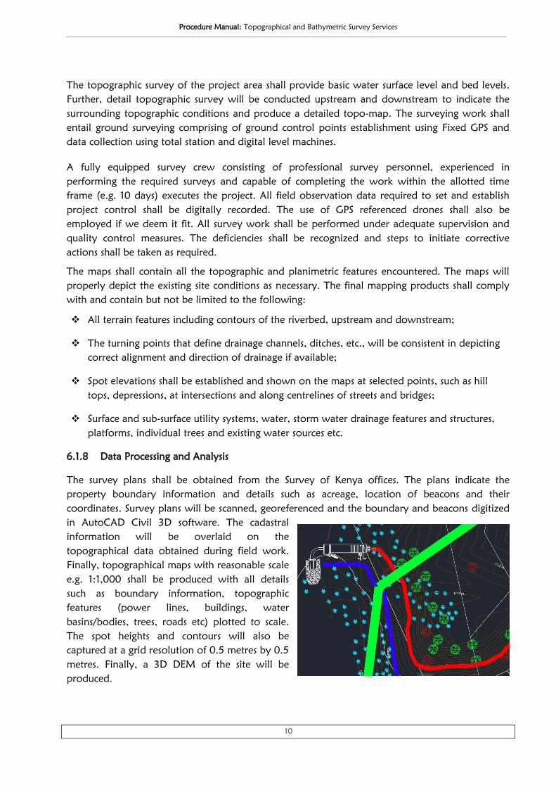
6.1.8 Data Processing and Analysis
The survey plans shall be obtained from the Survey of Kenya offices. The plans indicate the
property boundary information and details such as acreage, location of beacons and their
coordinates. Survey plans will be scanned, georeferenced and the boundary and beacons digitized
in AutoCAD Civil 3D software. The cadastral
information will be overlaid on the
topographical data obtained during field work.
Finally, topographical maps with reasonable scale
e.g. 1:1,000 shall be produced with all details
such as boundary information, topographic
features (power lines, buildings, water
basins/bodies, trees, roads etc) plotted to scale.
The spot heights and contours will also be
captured at a grid resolution of 0.5 metres by 0.5
metres. Finally, a 3D DEM of the site will be
produced.

Procedure Manual: Topographical and Bathymetric Survey Services
11
6.2 BATHYMETRIC SURVEY
6.2.1 Introduction
We propose to conduct the bathymetric survey using a combination of Garmin Striker 4 Mobile
device, Stonex S800A GNSS equipment, Ranging Rods and a Boat.
Fig 3: Bathymetric Survey Equipment
6.2.2 Methodology
We propose to employ Single-beam Bathymetric surveying method. Rather than sending out a
wide set of beams, single-beam bathymetry measures the water depth directly under the boat.
Single-beam surveys are generally used for smaller water bodies. A boat will be used to carry the
measuring instrument (echo-sounder) and take depth as well as co-ordinate data at designed
locations. The depth recordings are provided with 16 grey scales. The echo-sounder is fitted with
high precision GPS for recording co-ordinates with a maximum error of + or - 3 cm.
Fig. 4: Bathymetric Survey Methodology
BATHYMETRIC
SURVEY
Field Data
- GPS Coordinates
- Water Depth
Road & Power
Utility Networks
High Resolution
Satellite Images
Equipment
- GNSS Equipment
- Ranging Rods
- Garmin Striker 4
- A Boat & A Laptop
Topographical
Data/Maps
Data Analysis &
processing
BASE DATA
Procedure Manual: Topographical and Bathymetric Survey Services
12
6.2.3 Bathymetric Survey Process
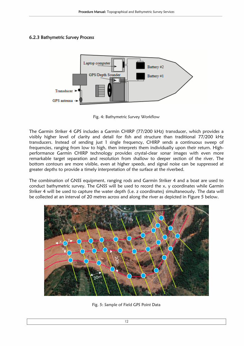
The Garmin Striker 4 GPS includes a Garmin CHIRP (77/200 kHz) transducer, which provides a
visibly higher level of clarity and detail for fish and structure than traditional 77/200 kHz
transducers. Instead of sending just 1 single frequency, CHIRP sends a continuous sweep of
frequencies, ranging from low to high, then interprets them individually upon their return. High-
performance Garmin CHIRP technology provides crystal-clear sonar images with even more
remarkable target separation and resolution from shallow to deeper section of the river. The
bottom contours are more visible, even at higher speeds, and signal noise can be suppressed at
greater depths to provide a timely interpretation of the surface at the riverbed.
The combination of GNSS equipment, ranging rods and Garmin Striker 4 and a boat are used to
conduct bathymetric survey. The GNSS will be used to record the x, y coordinates while Garmin
Striker 4 will be used to capture the water depth (i.e. z coordinates) simultaneously. The data will
be collected at an interval of 20 metres across and along the river as depicted in Figure 5 below.
Fig. 4: Bathymetric Survey Workflow
Fig. 5: Sample of Field GPS Point Data
x y
z

Procedure Manual: Topographical and Bathymetric Survey Services
13
The screen of the Garmin handheld GPS will display the water depth, bearing etc. at every point
along the river channel as shown in figure 6 below.
The data collected in the field will be analysed using ArcGIS Software to generate the digital
terrain of the riverbed. The river cross-section and longitudinal profiles will be produced in
AutoCAD software.
4.5 Surveying Crew Organization
The process of organizing the survey crew to carry out topographic survey of the project area
and its surroundings is very important. The ground surveying crew will consist of 2 survey crews
for topographic survey and one fixed GPS crew for transferring co-ordinate to project area and
for triangulation analysis. In addition, one boat operator and one bathymetric specialist form the
bathymetric survey crew. The necessary ground control points will be prepared by the ground
survey team prior the commencement of bathymetric survey and the two teams work closely to
facilitate the smooth accomplishment of the assignment.
6. LIST OF SOFTWARE
• AutoCAD Civil 3D – For topographical data processing in 3D such as heights of power lines.
• Esri’s ArcGIS 10.5 – Used to analyse vector data and creation of cartographic maps.
• Surfer 11 – The software will be used to smoothen the generated contours.
• MS Office Suite – MS word & Excel will be used for report writing, data analysis respectively.
Fig. 5: Sample of Garmin Striker 4 Bathymetric Data

Procedure Manual: Topographical and Bathymetric Survey Services
14
7. SURVEY EQUIPMENT
6.1 Automatic Level Machine
We intend to use Stonex DL 1000 automatic level machine
to establish vertical controls via levelling. It has a finely
tuned auto-collimation system. The proposed level machine
has a telescope with a magnification of 32x. It also comes
with a Pendulum compensator with magnetic damping
system. With a completely new small lightweight design, DL
1000 has excellent visibility of horizontal circle, superior gear
ratio for shock and vibration and improved tangents and knobs. Some of its Key features are:-
• Rapid, accurate, and stable automatic compensation;
• Ultra-short 20cm focusing and All-weather dependability;
• Endless fine horizontal and vertical adjustments.
6.2 Total Station
Stonex R1+ total station has been proposed to be used in
measuring horizontal angles and distances during the
establishment of horizontal controls. It has accuracy of 2” in
angular measurements. Built with legendary Topcon precision
and durability, the GTS-102N provides the professional a
dedicated lay-out solution construction. It has 2 screens, dot
matrix graphic LCD display. It has internal memory capable of storing up to 24,000 points of data
storage. This total station is ideal for this nature of work.
6.3 GNSS/RTK/Geodetic GPS
In survey process using RTK, the elevation points are taken at evenly
spaced distances (i.e. 25 m) along transects stratified from high to low
elevations. To navigate to each measurement point, the surveyor uses the
CAD gridline file uploaded to the RTK GPS map to aid in identifying the
stakeout points. The Stonex S800A can be configured with the radio and
cellular modem that best fits the project needs. We can choose from Digital UHF, CORS or Spread
Spectrum radio for sending corrections to the rover.

Procedure Manual: Topographical and Bathymetric Survey Services
15
8. SAMPLE DELIVERABLES
Contours on Satellite image A Digital Surface Model
Digital Elevation Model (DEM) Sample Shaded Relief
River Profile

Proposal: Topographical Survey, Preparation of Site Plan and Creation of a 3D Model for Kapa Oil Premises along Mombasa Road
16
9. PROPOSED WORK PLAN
ACTIVITY
TIME FRAME (DAYS)
NO. DESCRIPTION OF ACTIVITY D1 D2 D3 D4 D5 D6 D7 D8 D9 D10
1. Site Pre-visit
2. Preparation of the Proposal
3. Negotiation and Contract Signing
MILESTONE 1: Site Previsit, Proposal and Contract
4. Purchase of Maps from Survey of Kenya
5. Establishment of Ground Control Points
6. Topo & Bathymetric Survey–Data Collection
7. Data Processing and Maps/Plans Production
8. Analysis of Topo & Bathymetric Data
MILESTONE 2: Completion of Field work, Data Processing & Map Production
8. Printing of Maps/Plans – Size A0, A1 etc.
9. Presentation of All Deliverables
10. Hand over of Final Project Reports
MILESTONE 3: Handover of Evaluation and Final Report
Fig. 8: Proposed Work plan, Timelines and Milestones
*D = Day