Topic 5 Power Transmission Elements I - … · Topic 5 Power Transmission Elements I Topics: ......
27
© 2000 Alexander Slocum 5-1 Topic 5 Power Transmission Elements I Topics: • Transmissions • Pulleys • Winches • Belts & Cables • Wheels • Steering & Suspensions • Clutches & Differentials • Cams • Shafts • Couplings F W
Transcript of Topic 5 Power Transmission Elements I - … · Topic 5 Power Transmission Elements I Topics: ......
© 2000 Alexander Slocum 5-1
Topic 5Power Transmission Elements I
Topics:• Transmissions• Pulleys• Winches• Belts & Cables• Wheels• Steering & Suspensions• Clutches & Differentials• Cams• Shafts• Couplings
F
W
© 2000 Alexander Slocum 5-2
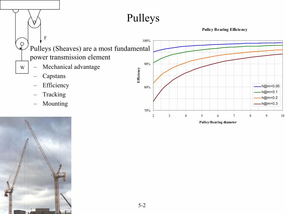
Pulley Bearing Efficiency
70%
80%
90%
100%
2 3 4 5 6 7 8 9 10
Pulley/Bearing diameter
Effi
cien
cy
h@m=0.05h@m=0.1h@m=0.2h@m=0.3
• Pulleys (Sheaves) are a most fundamental power transmission element
– Mechanical advantage– Capstans– Efficiency– Tracking– Mounting
F
W
Pulleys
© 2000 Alexander Slocum 5-3
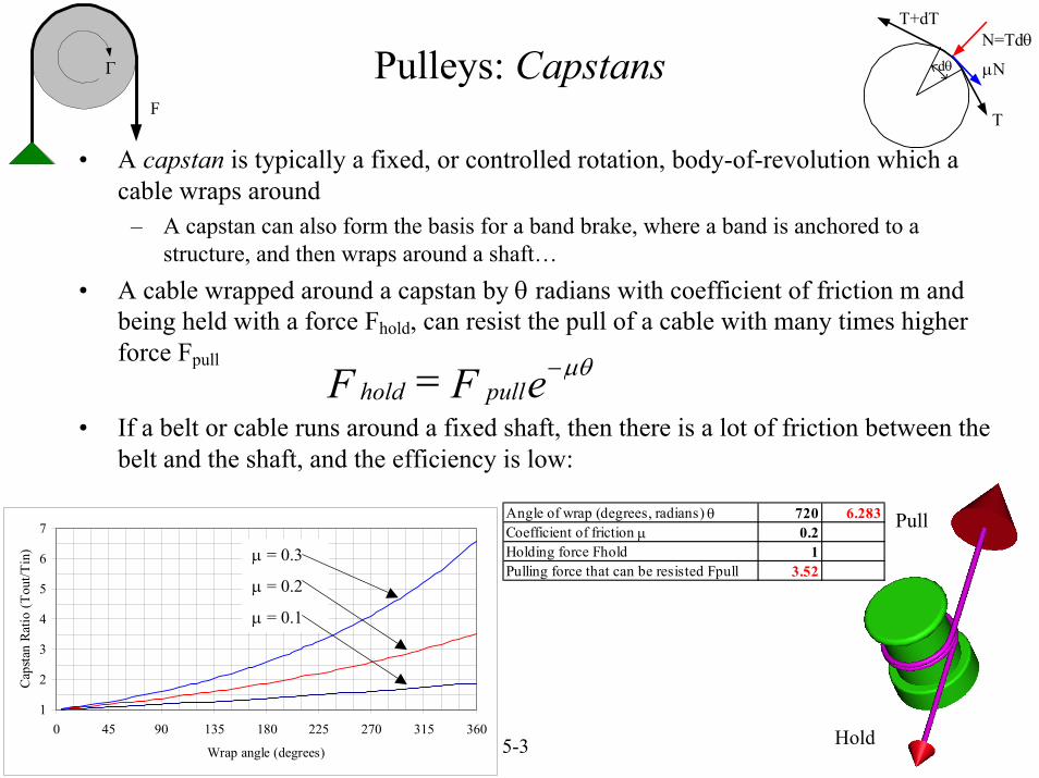
• A capstan is typically a fixed, or controlled rotation, body-of-revolution which a cable wraps around
– A capstan can also form the basis for a band brake, where a band is anchored to a structure, and then wraps around a shaft…
• A cable wrapped around a capstan by θ radians with coefficient of friction m and being held with a force Fhold, can resist the pull of a cable with many times higher force Fpull
• If a belt or cable runs around a fixed shaft, then there is a lot of friction between the belt and the shaft, and the efficiency is low:
hold pulleF F µθ−=
Hold
PullAngle of wrap (degrees, radians) θ 720 6.283Coefficient of friction µ 0.2Holding force Fhold 1Pulling force that can be resisted Fpull 3.52
F
Γ
T
dθ
T+dTN=Tdθ
µN
1
2
3
4
5
6
7
0 45 90 135 180 225 270 315 360
Wrap angle (degrees)
Caps
tan
Ratio
(Tou
t/Tin
) µ = 0.3
µ = 0.2
µ = 0.1
Pulleys: Capstans
© 2000 Alexander Slocum 5-4
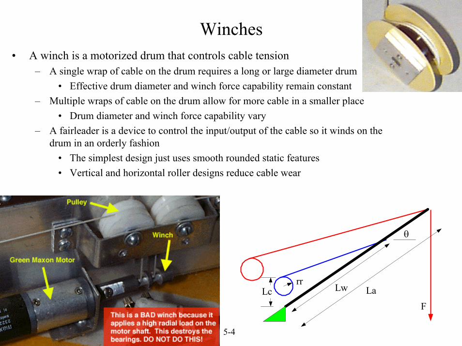
Winches• A winch is a motorized drum that controls cable tension
– A single wrap of cable on the drum requires a long or large diameter drum• Effective drum diameter and winch force capability remain constant
– Multiple wraps of cable on the drum allow for more cable in a smaller place• Drum diameter and winch force capability vary
– A fairleader is a device to control the input/output of the cable so it winds on the drum in an orderly fashion
• The simplest design just uses smooth rounded static features• Vertical and horizontal roller designs reduce cable wear
Lw LaLcrr
θ
F
© 2000 Alexander Slocum 5-5
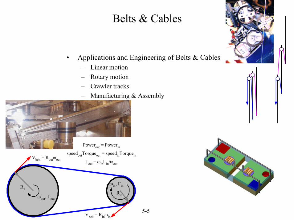
R1Rinωout, Γout
Vbelt = Routωout
Vbelt = Rinωin
ωin, Γin
Powerout = Powerin
speedoutTorqueout = speedinTorquein
Γout = ωinΓin/ωout
• Applications and Engineering of Belts & Cables– Linear motion– Rotary motion– Crawler tracks– Manufacturing & Assembly
Belts & Cables
© 2000 Alexander Slocum 5-6
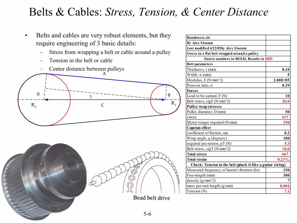
Belts & Cables: Stress, Tension, & Center Distance
• Belts and cables are very robust elements, but they require engineering of 3 basic details:
– Stress from wrapping a belt or cable around a pulley– Tension in the belt or cable– Center distance between pulleys
θ φ
A
CR2R1
γ
Bandstress.xlsBy Alex S locumLast modified 4/22/02by Alex S locumStress in a flat belt wrapped around a pulley
Belt parametersThickness, t (mm) 0.10Width, w (mm) 5Modulus, E (N/mm^2) 2.00E+05Poisson ratio, n 0.29ForcesLoad to be carried, F (N) 10Belt stress, sigF (N/mm^2) 20.0Pulley wrap stressesPulley diameter, D (mm) 50stress 437 Motor torque required (N-mm) 250Capstan effectcoefficient of friction, mu 0.2Wrap angle, q (degrees) 180required pre-tenion, pT (N) 5.3Belt stress, sigT (N/mm^2) 10.6Total stress 467 Total strain 0.23%
Measured frequency of lateral vibration (hz) 150Free-length (mm) 300density (g/mm^3) 7mass per unit length (g/mm) 0.004Tension (N) 7.1
Enters numbers in BOLD, Results in RED
Check: Tension in the belt (pluck it like a guitar string)
© 2000 Alexander Slocum 5-7
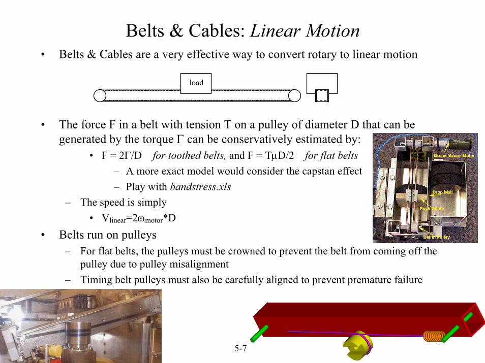
Belts & Cables: Linear Motion• Belts & Cables are a very effective way to convert rotary to linear motion
• The force F in a belt with tension T on a pulley of diameter D that can be generated by the torque Γ can be conservatively estimated by:
• F = 2Γ/D for toothed belts, and F = TµD/2 for flat belts– A more exact model would consider the capstan effect– Play with bandstress.xls
– The speed is simply• Vlinear=2ωmotor*D
• Belts run on pulleys– For flat belts, the pulleys must be crowned to prevent the belt from coming off the
pulley due to pulley misalignment– Timing belt pulleys must also be carefully aligned to prevent premature failure
load
© 2000 Alexander Slocum 5-8
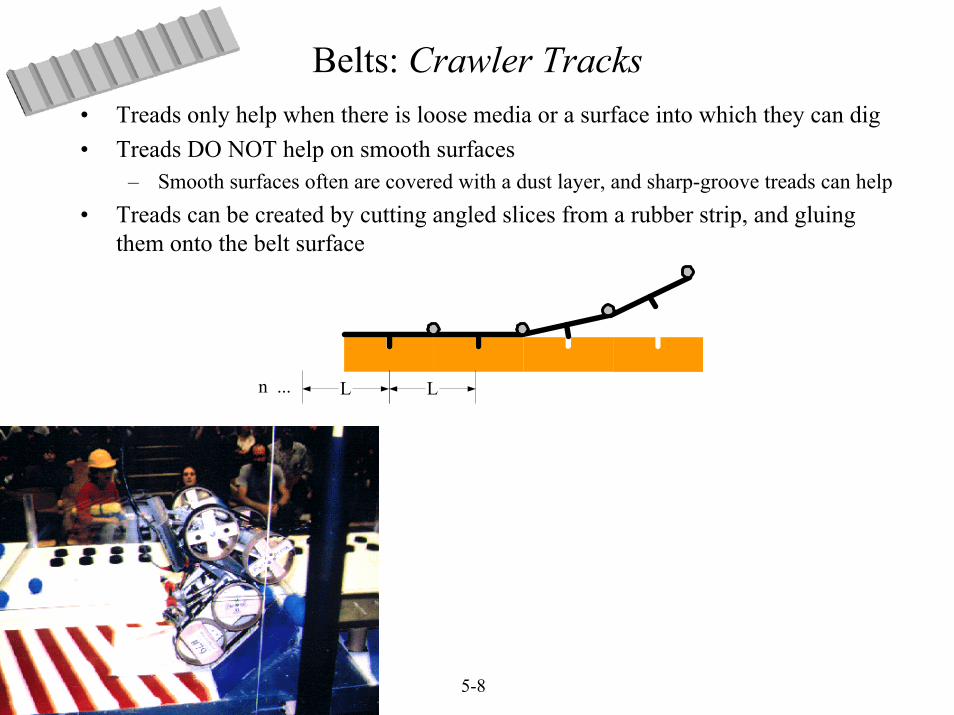
• Treads only help when there is loose media or a surface into which they can dig• Treads DO NOT help on smooth surfaces
– Smooth surfaces often are covered with a dust layer, and sharp-groove treads can help• Treads can be created by cutting angled slices from a rubber strip, and gluing
them onto the belt surface
LLn ...
Belts: Crawler Tracks
© 2000 Alexander Slocum 5-9
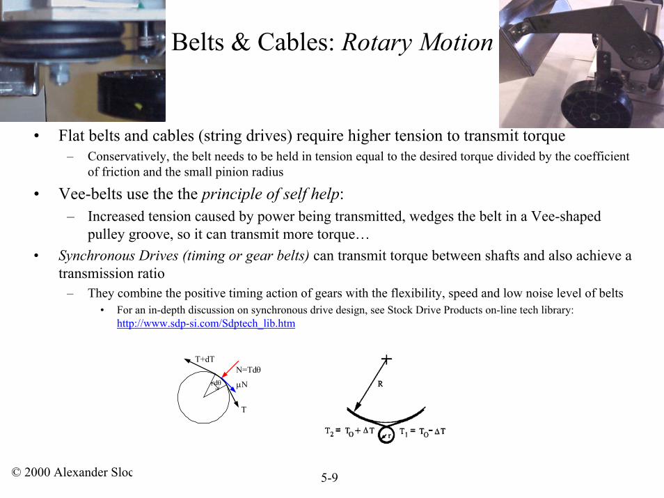
• Flat belts and cables (string drives) require higher tension to transmit torque– Conservatively, the belt needs to be held in tension equal to the desired torque divided by the coefficient
of friction and the small pinion radius
• Vee-belts use the the principle of self help:– Increased tension caused by power being transmitted, wedges the belt in a Vee-shaped
pulley groove, so it can transmit more torque…• Synchronous Drives (timing or gear belts) can transmit torque between shafts and also achieve a
transmission ratio– They combine the positive timing action of gears with the flexibility, speed and low noise level of belts
• For an in-depth discussion on synchronous drive design, see Stock Drive Products on-line tech library:http://www.sdp-si.com/Sdptech_lib.htm
T
dθ
T+dTN=Tdθ
µN
Belts & Cables: Rotary Motion
© 2000 Alexander Slocum 5-10
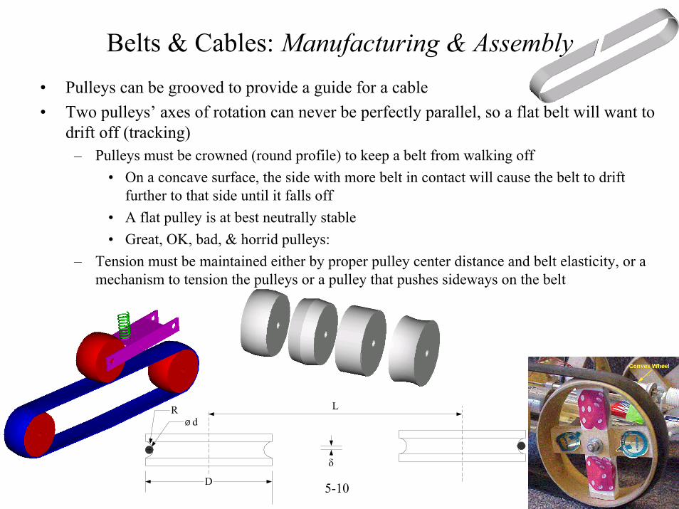
Belts & Cables: Manufacturing & Assembly• Pulleys can be grooved to provide a guide for a cable• Two pulleys’ axes of rotation can never be perfectly parallel, so a flat belt will want to
drift off (tracking)– Pulleys must be crowned (round profile) to keep a belt from walking off
• On a concave surface, the side with more belt in contact will cause the belt to drift further to that side until it falls off
• A flat pulley is at best neutrally stable• Great, OK, bad, & horrid pulleys:
– Tension must be maintained either by proper pulley center distance and belt elasticity, or a mechanism to tension the pulleys or a pulley that pushes sideways on the belt
L
D
Ø dR
δ
© 2000 Alexander Slocum 5-11
Ø D
F
FM
Nf
FS
h
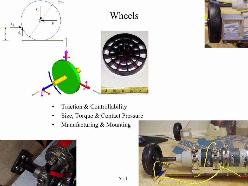
Wheels
• Traction & Controllability• Size, Torque & Contact Pressure • Manufacturing & Mounting
© 2000 Alexander Slocum 5-12
Torque-Speed for Bosch Motor(MS-L 2/98)
00.20.40.60.8
11.21.41.61.8
0 10 20 30 40 50 60 70 80 90 100
Speed (RPM)
Torq
ue (N
m)
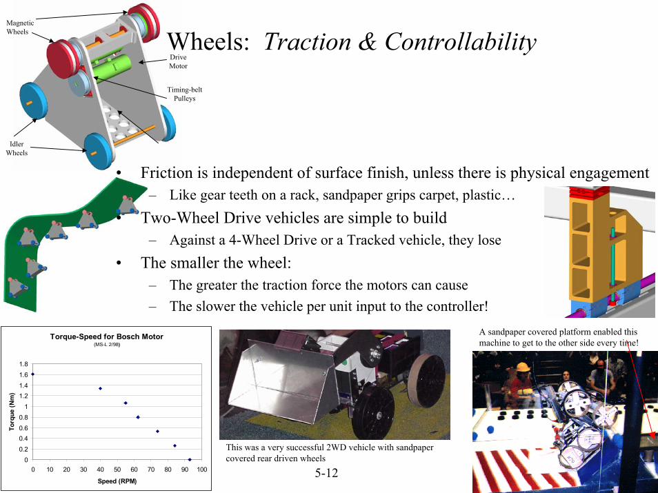
A sandpaper covered platform enabled this machine to get to the other side every time!
Magnetic Wheels
Idler Wheels
Drive Motor
Timing-beltPulleys
Wheels: Traction & Controllability
• Friction is independent of surface finish, unless there is physical engagement– Like gear teeth on a rack, sandpaper grips carpet, plastic…
• Two-Wheel Drive vehicles are simple to build– Against a 4-Wheel Drive or a Tracked vehicle, they lose
• The smaller the wheel:– The greater the traction force the motors can cause– The slower the vehicle per unit input to the controller!
This was a very successful 2WD vehicle with sandpaper covered rear driven wheels
© 2000 Alexander Slocum 5-13
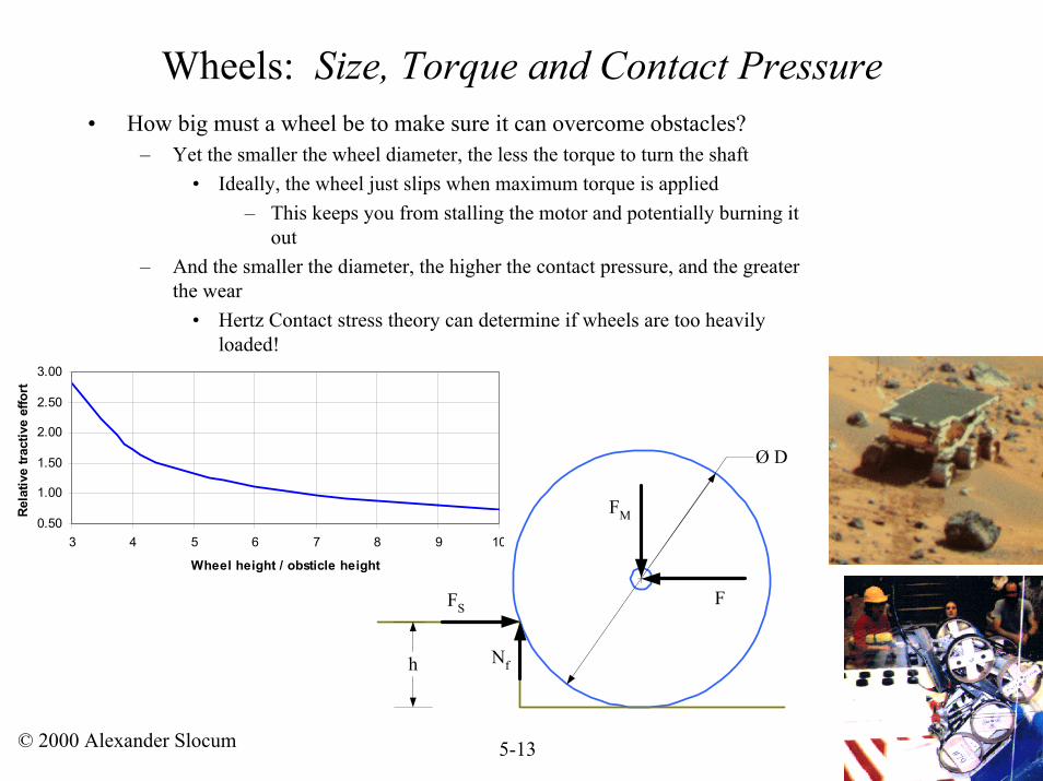
Wheels: Size, Torque and Contact Pressure• How big must a wheel be to make sure it can overcome obstacles?
– Yet the smaller the wheel diameter, the less the torque to turn the shaft• Ideally, the wheel just slips when maximum torque is applied
– This keeps you from stalling the motor and potentially burning it out
– And the smaller the diameter, the higher the contact pressure, and the greater the wear
• Hertz Contact stress theory can determine if wheels are too heavily loaded!
Ø D
F
FM
Nf
FS
h
0.50
1.00
1.50
2.00
2.50
3.00
3 4 5 6 7 8 9 10
Wheel height / obsticle height
Rela
tive
tract
ive
effo
rt
© 2000 Alexander Slocum 5-14
Wheels: Manufacturing & Mounting
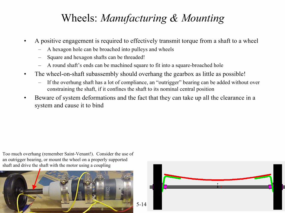
• A positive engagement is required to effectively transmit torque from a shaft to a wheel– A hexagon hole can be broached into pulleys and wheels– Square and hexagon shafts can be threaded!– A round shaft’s ends can be machined square to fit into a square-broached hole
• The wheel-on-shaft subassembly should overhang the gearbox as little as possible!– If the overhung shaft has a lot of compliance, an “outrigger” bearing can be added without over
constraining the shaft, if it confines the shaft to its nominal central position• Beware of system deformations and the fact that they can take up all the clearance in a
system and cause it to bind
Too much overhang (remember Saint-Venant!). Consider the use of an outrigger bearing, or mount the wheel on a properly supportedshaft and drive the shaft with the motor using a coupling
© 2000 Alexander Slocum 5-15
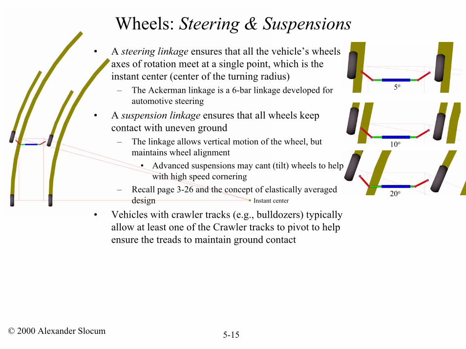
Wheels: Steering & Suspensions• A steering linkage ensures that all the vehicle’s wheels
axes of rotation meet at a single point, which is the instant center (center of the turning radius)
– The Ackerman linkage is a 6-bar linkage developed for automotive steering
• A suspension linkage ensures that all wheels keep contact with uneven ground
– The linkage allows vertical motion of the wheel, but maintains wheel alignment
• Advanced suspensions may cant (tilt) wheels to help with high speed cornering
– Recall page 3-26 and the concept of elastically averaged design
• Vehicles with crawler tracks (e.g., bulldozers) typically allow at least one of the Crawler tracks to pivot to help ensure the treads to maintain ground contact
5o
10o
20o
Instant center
© 2000 Alexander Slocum 5-16
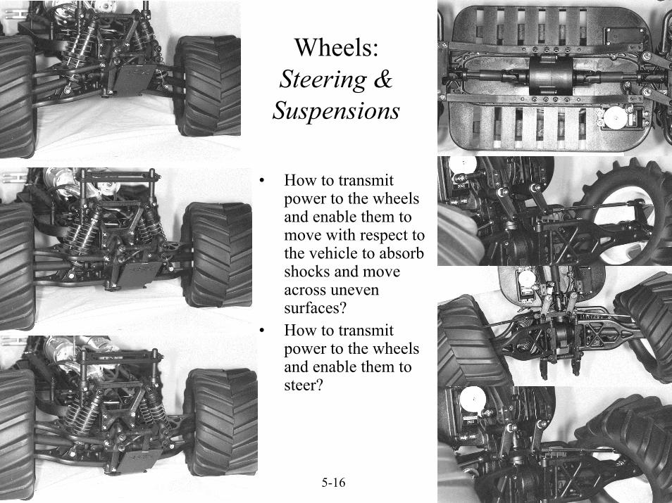
• How to transmit power to the wheels and enable them to move with respect to the vehicle to absorb shocks and move across uneven surfaces?
• How to transmit power to the wheels and enable them to steer?
Wheels: Steering &
Suspensions
© 2000 Alexander Slocum 5-17
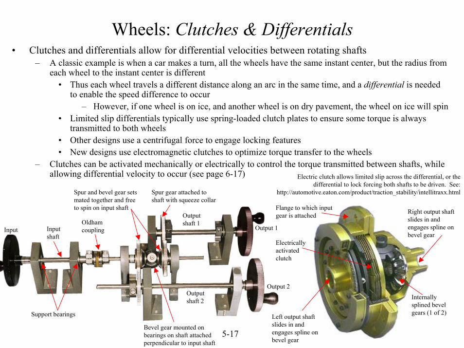
Wheels: Clutches & Differentials
Electric clutch allows limited slip across the differential, or the differential to lock forcing both shafts to be driven. See:
http://automotive.eaton.com/product/traction_stability/intellitraxx.html
• Clutches and differentials allow for differential velocities between rotating shafts– A classic example is when a car makes a turn, all the wheels have the same instant center, but the radius from
each wheel to the instant center is different• Thus each wheel travels a different distance along an arc in the same time, and a differential is needed
to enable the speed difference to occur– However, if one wheel is on ice, and another wheel is on dry pavement, the wheel on ice will spin
• Limited slip differentials typically use spring-loaded clutch plates to ensure some torque is always transmitted to both wheels
• Other designs use a centrifugal force to engage locking features• New designs use electromagnetic clutches to optimize torque transfer to the wheels
– Clutches can be activated mechanically or electrically to control the torque transmitted between shafts, while allowing differential velocity to occur (see page 6-17)
Input
Spur gear attached to shaft with squeeze collar
Oldham coupling
Support bearings
Output 2
Output 1Input shaft
Output shaft 2
Output shaft 1
Spur and bevel gear sets mated together and free to spin on input shaft Right output shaft
slides in and engages spline on bevel gear
Left output shaft slides in and engages spline on bevel gear
Flange to which input gear is attached
Electrically activated clutch
Internally splined bevel gears (1 of 2)
Bevel gear mounted on bearings on shaft attached perpendicular to input shaft
© 2000 Alexander Slocum 5-18
Special thanks to Scott Hover from Len Industries in Leslie Michigan for the sketch, pictures, and explanation!
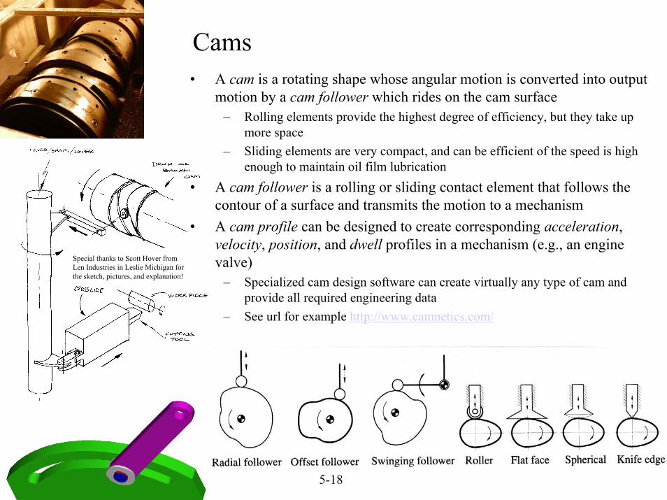
• A cam is a rotating shape whose angular motion is converted into output motion by a cam follower which rides on the cam surface
– Rolling elements provide the highest degree of efficiency, but they take up more space
– Sliding elements are very compact, and can be efficient of the speed is high enough to maintain oil film lubrication
• A cam follower is a rolling or sliding contact element that follows the contour of a surface and transmits the motion to a mechanism
• A cam profile can be designed to create corresponding acceleration, velocity, position, and dwell profiles in a mechanism (e.g., an engine valve)
– Specialized cam design software can create virtually any type of cam and provide all required engineering data
– See url for example http://www.camnetics.com/
Cams
© 2000 Alexander Slocum 5-19
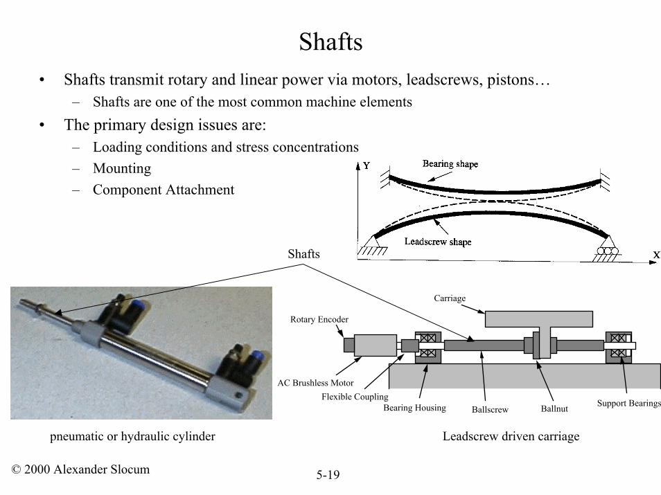
Shafts• Shafts transmit rotary and linear power via motors, leadscrews, pistons…
– Shafts are one of the most common machine elements• The primary design issues are:
– Loading conditions and stress concentrations– Mounting– Component Attachment
BallscrewSupport BearingsBearing Housing Ballnut
Carriage
AC Brushless Motor
Rotary Encoder
Flexible Coupling
Shafts
pneumatic or hydraulic cylinder Leadscrew driven carriage
© 2000 Alexander Slocum 5-20
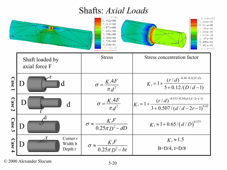
Shafts: Axial Loads
Stress concentration factorStress
D dr
r
2
4t FKd
σπ
=0.36 0.2( / )( / )1
5 0.12 /( / 1)
D d
tr d
K D d
− −
= ++ −
Dd
( )0.2751 0.65 / /t d DK ≈ +20.25tFK
dDDσ
π≈
−
2
4t FKd
σπ
=
20.25tFK
btDσ
π≈
−
1.5tK ≈
0.511 0.34( /( 2 ) 1)
0.42( / )1
3 0.507 / ( / 2 1)
d d r
tr d
Kd d r
− − − −
= ++ − −
Dr
Case 1 C
ase 2 Case 3 C
ase 4
Shaft loaded by axial force F
d
Corner rWidth bDepth t
D B=D/4, t=D/8
© 2000 Alexander Slocum 5-21
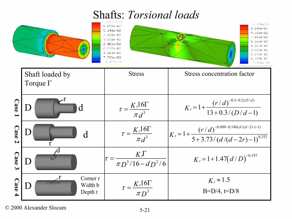
Shafts: Torsional loads
Stress concentration factorStressShaft loaded by Torque Γ
D dr
Dr
rD
Corner rWidth bDepth t
3
16tKd
τπ
Γ=
0.3 0.2( / )( / )113 0.3 / ( / 1)
D d
tr d
KD d
− −
= ++ −
3
16tKd
τπ
Γ=
0.609 0.146( /( 2 ) 1)
0.252( / )1
5 3.73 / ( /( 2 ) 1)
d d r
tr d
Kd d r
− − − −
= ++ − −
1.5tK ≈
3
16tKD
τπ
Γ=
d
Dd
3 2/16 / 6tK
dD Dτ
πΓ
=−
( ) 0.1971 1.47 /t d DK−= +
Case 1 C
ase 2 Case 3 C
ase 4 B=D/4, t=D/8
© 2000 Alexander Slocum 5-22
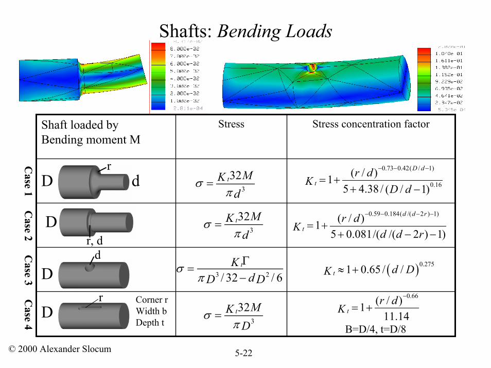
Shafts: Bending Loads
Stress concentration factorStressShaft loaded by Bending moment M
D dr
Dd
r
3
32t MKd
σπ
=
3 2/ 32 / 6tK
dD Dσ
πΓ
=−
3
32t MKD
σπ
=
0.66( / )111.14t
r dK
−
= +
B=D/4, t=D/8
0.73 0.42( / 1)
0.16( / )1
5 4.38 / ( / 1)
D d
tr d
KD d
− − −
= ++ −
( )0.2751 0.65 / /t d DK ≈ +
3
32t MKd
σπ
=0.59 0.184( /( 2 ) 1)( / )1
5 0.081/( /( 2 ) 1)
d d r
tr d
K d d r
− − − −
= ++ − −
Dr, d
Case 1 C
ase 2 Case 3 C
ase 4
Corner rWidth bDepth t
D
© 2000 Alexander Slocum 5-23
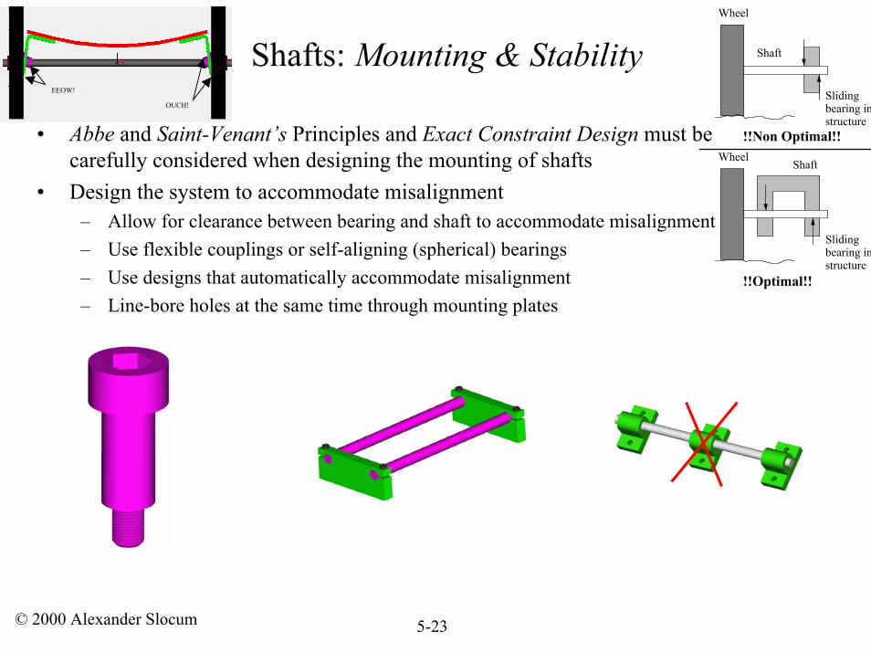
Wheel
Shaft
Sliding bearing in structure
!!Non Optimal!! Wheel
Shaft
Sliding bearing in structure
!!Optimal!!
• Abbe and Saint-Venant’s Principles and Exact Constraint Design must be carefully considered when designing the mounting of shafts
• Design the system to accommodate misalignment– Allow for clearance between bearing and shaft to accommodate misalignment– Use flexible couplings or self-aligning (spherical) bearings– Use designs that automatically accommodate misalignment– Line-bore holes at the same time through mounting plates
OUCH!
EEOW!
Shafts: Mounting & Stability
© 2000 Alexander Slocum 5-24
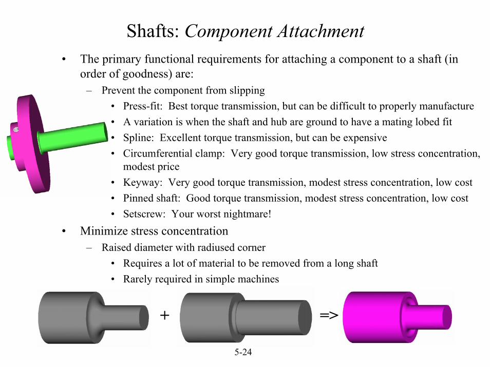
Shafts: Component Attachment• The primary functional requirements for attaching a component to a shaft (in
order of goodness) are:– Prevent the component from slipping
• Press-fit: Best torque transmission, but can be difficult to properly manufacture• A variation is when the shaft and hub are ground to have a mating lobed fit• Spline: Excellent torque transmission, but can be expensive• Circumferential clamp: Very good torque transmission, low stress concentration,
modest price• Keyway: Very good torque transmission, modest stress concentration, low cost• Pinned shaft: Good torque transmission, modest stress concentration, low cost• Setscrew: Your worst nightmare!
• Minimize stress concentration– Raised diameter with radiused corner
• Requires a lot of material to be removed from a long shaft• Rarely required in simple machines
=>+
© 2000 Alexander Slocum 5-25
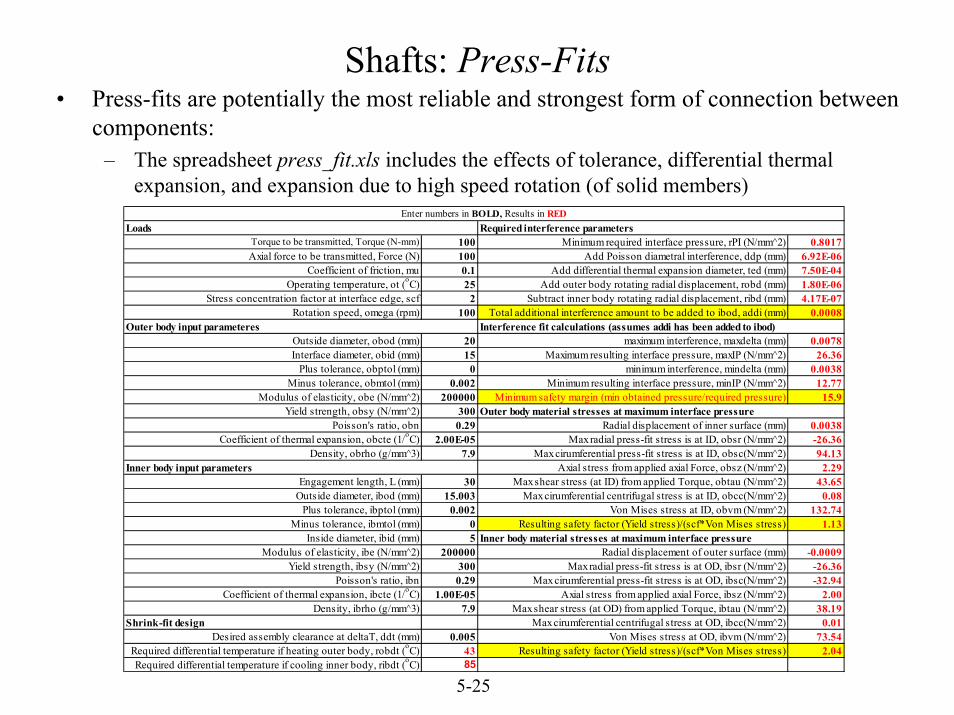
• Press-fits are potentially the most reliable and strongest form of connection between components:
– The spreadsheet press_fit.xls includes the effects of tolerance, differential thermal expansion, and expansion due to high speed rotation (of solid members)
Shafts: Press-Fits
Torque to be transmitted, Torque (N-mm) 100 Minimum required interface pressure, rPI (N/mm^2) 0.8017Axial force to be transmitted, Force (N) 100 Add Poisson diametral interference, ddp (mm) 6.92E-06
Coefficient of friction, mu 0.1 Add differential thermal expansion diameter, ted (mm) 7.50E-04Operating temperature, ot (oC) 25 Add outer body rotating radial displacement, robd (mm) 1.80E-06
Stress concentration factor at interface edge, scf 2 Subtract inner body rotating radial displacement, ribd (mm) 4.17E-07Rotation speed, omega (rpm) 100 Total additional interference amount to be added to ibod, addi (mm) 0.0008
Outside diameter, obod (mm) 20 maximum interference, maxdelta (mm) 0.0078Interface diameter, obid (mm) 15 Maximum resulting interface pressure, maxIP (N/mm^2) 26.36
Plus tolerance, obptol (mm) 0 minimum interference, mindelta (mm) 0.0038Minus tolerance, obmtol (mm) 0.002 Minimum resulting interface pressure, minIP (N/mm^2) 12.77
Modulus of elasticity, obe (N/mm^2) 200000 Minimum safety margin (min obtained pressure/required pressure) 15.9Yield strength, obsy (N/mm^2) 300
Poisson's ratio, obn 0.29 Radial displacement of inner surface (mm) 0.0038Coefficient of thermal expansion, obcte (1/oC) 2.00E-05 Max radial press-fit stress is at ID, obsr (N/mm^2) -26.36
Density, obrho (g/mm^3) 7.9 Max cirumferential press-fit stress is at ID, obsc(N/mm^2) 94.13Axial stress from applied axial Force, obsz (N/mm^2) 2.29
Engagement length, L (mm) 30 Max shear stress (at ID) from applied Torque, obtau (N/mm^2) 43.65Outside diameter, ibod (mm) 15.003 Max cirumferential centrifugal stress is at ID, obcc(N/mm^2) 0.08
Plus tolerance, ibptol (mm) 0.002 Von Mises stress at ID, obvm (N/mm^2) 132.74Minus tolerance, ibmtol (mm) 0 Resulting safety factor (Yield stress)/(scf*Von Mises stress) 1.13
Inside diameter, ibid (mm) 5 Inner body material stresses at maximum interface pressureModulus of elasticity, ibe (N/mm^2) 200000 Radial displacement of outer surface (mm) -0.0009
Yield strength, ibsy (N/mm^2) 300 Max radial press-fit stress is at OD, ibsr (N/mm^2) -26.36Poisson's ratio, ibn 0.29 Max cirumferential press-fit stress is at OD, ibsc(N/mm^2) -32.94
Coefficient of thermal expansion, ibcte (1/oC) 1.00E-05 Axial stress from applied axial Force, ibsz (N/mm^2) 2.00Density, ibrho (g/mm^3) 7.9 Max shear stress (at OD) from applied Torque, ibtau (N/mm^2) 38.19
Shrink-fit design Max cirumferential centrifugal stress at OD, ibcc(N/mm^2) 0.01Desired assembly clearance at deltaT, ddt (mm) 0.005 Von Mises stress at OD, ibvm (N/mm^2) 73.54
Required differential temperature if heating outer body, robdt (oC) 43 Resulting safety factor (Yield stress)/(scf*Von Mises stress) 2.04Required differential temperature if cooling inner body, ribdt (oC) 85
Inner body input parameters
Outer body material stresses at maximum interface pressure
Enter numbers in BOLD, Results in RED
Interference fit calculations (assumes addi has been added to ibod)
Required interference parametersLoads
Outer body input parameteres
© 2000 Alexander Slocum 5-26
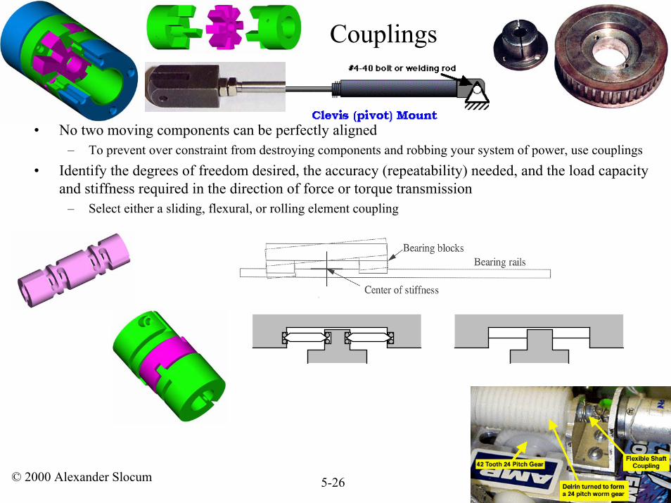
• No two moving components can be perfectly aligned– To prevent over constraint from destroying components and robbing your system of power, use couplings
• Identify the degrees of freedom desired, the accuracy (repeatability) needed, and the load capacity and stiffness required in the direction of force or torque transmission
– Select either a sliding, flexural, or rolling element coupling
Couplings
© 2000 Alexander Slocum 5-27
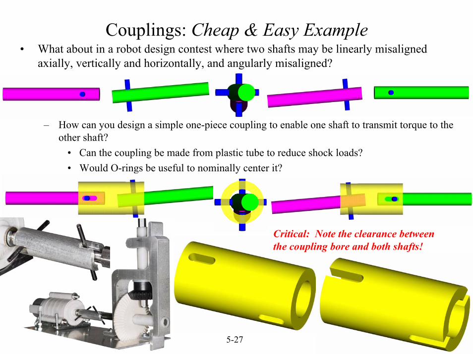
Couplings: Cheap & Easy Example• What about in a robot design contest where two shafts may be linearly misaligned
axially, vertically and horizontally, and angularly misaligned?
– How can you design a simple one-piece coupling to enable one shaft to transmit torque to the other shaft?
• Can the coupling be made from plastic tube to reduce shock loads? • Would O-rings be useful to nominally center it?
Critical: Note the clearance between the coupling bore and both shafts!