Uncertainties in Small-Angle Measurement Systems Used to Calibrate Angle Artifacts

Topic 3: Angle measurement
– traversing

Aims
-Learn what control surveys are and why these are an essential part of surveying
-Understand rectangular and polar co-ordinates and how to transform between the
two
-Learn how to carry out a traverse

Control Surveys
All measurements taken for engineering surveys are based on a network of
horizontal and vertical reference points called control points.
These networks are used on site in the preparation of maps and plans, they are
required for dimensional control (setting out) and are essential in deformation
monitoring.
Because all surveying needs control points at the start of any engineering or
construction project a control survey must be carried out in which the positions of
the control points are established.
The positions of horizontal control are usually specified in rectangular (x and y)
coordinates.

Rectangular co-ordinates
Any point P, has the coordinates known as easting Ep and northing Np quoted in the
order Ep, Np.

Calculation of rectangular co-ordinates
On a coordinate grid, the direction of a line between two points is know as its
bearing. The whole circle bearing of a line is measured in a clockwise direction in
the range 0 to 360°.

The following figure shows the plan of two points A and B on a rectangular grid. If
the coordinates of A(EA , NA) are known, the coordinates of B (EB , NB) are obtained
as follows:
Where:
∆EAB = the eastings difference from A to B
∆NAB = the northings difference from A to B
DAB = the horizontal distance from A to B
θAB = the whole circle bearing from A to B

Example: The coordinates of point A are 311.617mE, 447.245mN. Calculate the
coordinates of point B, where DAB = 57.916M and θAB = 37°11’20’’ and point C
where DAC = 85.071m and θAC = 205°33’55’’
Polar co-ordinates
Another coordinate system used in surveying is the polar coordinate system. Here
a point B is located with reference to point A by a polar coordinates D and θ.

D is the horizontal distance from A to B and θ is the whole circle bearing of the line
A to B.
For the reverse of the previous example where the coordinates are know for both
points it is possible to compute the whole circle bearing and horizontal distance of
the line between the two points. This is known as rectangular to polar coordinate
conversion.
Example: The coordinates of A and B are EA = 469.721m, NA = 338.466m and EB =
501.035m, NB = 310.617m. Calculate the horizontal distance DAB and the whole
circle bearing θAB.
m
NNEE
NED
ABAB
ABABAB
906.41
)446.338617.310()721.469035.501(
)()(
22
22
22
=
−+−=
−+−=
∆+∆=

To calculate θAB a sketch of the line AB must be made in order to identify which
quadrant the angle is in (as different equations apply for each quadrant):

= 131°38’ 53’’
TraversingA traverse is a means of providing horizontal control in which the rectangular
coordinates of a series of control points located are a site are determined from a
combination of angle and distance measurements.
oo
AB
AB
AB
N
E180
849.27
314.31tan180tan
11+
−=+
∆
∆=
−−θ

Each point on a traverse is called a traverse station and these must first be located
well and marked with ground markers before surveying commences:

Procedure for Traversing
When angle ABC is measured:
At A a tripod target is set up centred and levelled, at B a theodolite or total station is
set up, levelled and centred as normal. At C another tripod target is set up as for A.
This enables the horizontal angle at B to be recorded and if a total station is being
used the distances BA and BC can be measured.
When the angle BCD is measured:
At A the tripod target are moved to D, where the target is centred and levelled as
before. At B the total station or theodolite is unclamped and interchanged with the
target at C (the tripods can remain in the same place and there is no need to re-
centre them). The horizontal angle at C can now be measured along with the
distances CB and CD. The distance CB will provide a check for error in the
previous BC measurement.

When the angle CDE is measured:
At B the tripod and target are moved to E. The theodolite or total station at C is
interchanged with the target at D.
The process is repeated for the whole traverse, if 4 or more tripods are used this
speeds up the process.
Traverse CalculationsTraverse calculations involve the calculation of the 1) whole circle bearings 2) the
coordinate differences and 3) the coordinates of each control point. To illustrate
these calculations we will use the traverse ABCEDFA below throughout:


Errors and Misclosure
The first part of a traverse calculation is to check that the observed angles sum to
their required value.
Sum of internal angles = (2n - 4) x 90o
Sum of External angles = (2n + 4) x 90o , n is the number of angle measured
If on summing these values a misclosure is found, it is divided equally between the
station points if it is acceptable. Acceptability of misclosure E for traversing is given
by:
Where K is a multiplication factor from 1 to 3 depending on weather conditions. S is
the smallest reading interval on the theodolite (e.g. 20’’, 5’’ or 1’’) and n is the
number of angle measured.
Taking our traverse ABCDEFA the misclosure is calculated and redistributed as
follows:
nKSE ±=


Calculation of Whole Circle Bearings
To calculate the coordinates of a control point the WCB must be known as we saw
earlier. This is done according to the following formulae:

Calculation of Whole Circle Bearings
To calculate the coordinates of a control point the WCB must be known as we saw
earlier. This is done according to the following formulae:

Forward bearing YZ = Back bearing YX + (for the above example)
In general
Forward bearing = back bearing + left hand angle
A forward bearing is a bearing in the direction of the traverse e.g. XY and YZ, a
back bearing is a bearing in the opposite direction to the traverse e.g. YX and ZY.
Forward and back bearing differ by ±180°.
The left hand angle is the angle between the bearing lines at a control station that
lies to the left of the station relative to the direction of the traverse, i.e. the internal
angle for anticlockwise traverses and the external angle for clockwise traverses.
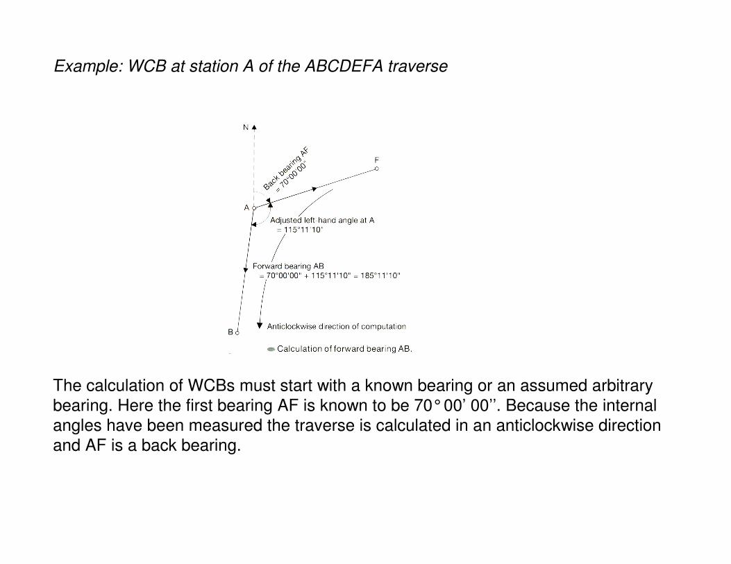
Example: WCB at station A of the ABCDEFA traverse
The calculation of WCBs must start with a known bearing or an assumed arbitrary
bearing. Here the first bearing AF is known to be 70°00’ 00’’. Because the internal
angles have been measured the traverse is calculated in an anticlockwise direction
and AF is a back bearing.

Forward bearing AB = back bearing AF + adjusted left hand angle at A
= 70°00’ 00’’ + 115°11’ 10’’ = 185°11’ 10’’ (WCB at A)
Example : WCB at station B of the ABCDEFA traverse

Forward bearing BC = back bearing BA + adjusted left hand angle at B
To convert the forward bearing AB into a back bearing BA we add or subtract 180°.
Back bearing BA = 185°11’ 10’’ ±180°
= 05°11’ 10’’
Forward bearing BX = 05°11’ 10’’ + 95o 00’ 00’’ = 100°11’ 10’’ (WCB at B)
The WCBs of all other stations are carried out in a similar manner. To finalise this
section of the calculations the final forward FA bearing must equal the first back
bearing AF (250°is equivalent to 70°in this case as shown in the next slide).


Calculation of Coordinate Differences
The next stage of the traverse calculation is to determine the coordinate differences
of the traverse lines ∆E, ∆N.
Example: Traverse ABCDEFA, line AB + BC


Error Check!
In order to assess the accuracy of the traverse ∑∆E (should) = 0 and ∑∆N (should)
= 0, since the traverse starts and finishes in the same place. The errors in this
summation eE and eN are:


Coordinate Differences : Bowditch Adjustment Method
Following calculation of ∆E, ∆N and the misclosure errors eE and eN an
adjustment of those errors δE, δN must be made. This method is most suitable for
traverses carried out using steel tapes
Adjustment to ∆E (or ∆N) for a traverse line
= δE (or δN) = - eE (or -eN) x length of traverse line / total length of traverse

Coordinate Differences : Equal Adjustment MethodThis adjustment method is most suited for traverses carried out with total stations
Calculation of CoordinatesRecalling from earlier that the coordinates of a point are calculated as follows for
points B and C:
EA, NA were given as 350.000mE, 500.000mN
EB = EA ± ∆EAB = 350 – 7.768 = 342.232mE
NB = NA ± ∆NAB = 500 – 85.517 = 414.483mN
This process is repeated until point A is rechecked as shown on the next slide:


Further Examples
Below the angles and distances for traverse A1234A are shown. The coordinates of
A are 642.515mE , 483.980mN. the traverse is oriented to existing control point B
(548.005mE, 594.279mN). Calculate the coordinates of stations 1-4.