Topic 1 different attributes that characterize sensors ETEC 6405.
33
Topic 1 different attributes that characterize sensors ETEC 6405
-
Upload
delilah-walker -
Category
Documents
-
view
220 -
download
0
Transcript of Topic 1 different attributes that characterize sensors ETEC 6405.

Topic 1 different attributes that characterize sensors
ETEC 6405

Sensors and transducers
• Analogue signal– this is a continuous signal.• Sensors measure physical phenomenon. Some physical
processes are –• Angular or linear position• Acceleration• Temperature• Pressure• Stress• Light intensity• Sound

Properties by which we characterize sensors
• -Accuracy: maximum difference between the indicated and the actual reading.
Maximum error or accuracy
ProblemA sensor with an accuracy of 10 mm has a position reading of 1.34 meters. What is the maximum and minimum possible readings for this sensor based on the sensors accuracy?
Resolution
• Resolution: used in systems that step through readings. The smallest increment the sensor can detect.
length
resolution
Measurements from A sensor span a distance of 3 meters in 50 increments. What is the resolution?

• Repeatability: When a sensor measurement is repeated and there are errors associated with the measurement, we can use a standard deviation to describe repeatability.
• Linearity: A linear relationship between the input phenomena of the device relative to the output to another device
• Precision: Considers accuracy, repeatability of the device relative to another device
• Range: Natural limits of a sensor.• Dynamic Response: frequency range for a sensor, i.e. from
1KHz to 10KHz.• Calibration: this is the relationship between the input
phenomena and the sensor output.• Cost: sensor pricing, generally more precision equals more
cost.• Environment: Factors which affect the sensor performance
i.e. humidity, temp, etc

Angular Displacement
• Potentiometers• The wiper
moves across the resistive film, changing the resistance between V1 and V2
• Potentiometers are used as voltage dividers

Encoder disk
• There are two types of encoder disks, relative encoders and absolute encoders


Tacogenerator
• If ω is the angular velocity of the shaft, the output voltage of the tachometer is given by
• where k is the gain constant of the tachometer.

Variable reluctance tachometer• When the magnetic moves past a stationary
pick-up coil, current is induced. • For each rotation of the shaft there is a pulse in
the coil.• This technique often requires some signal• conditioning circuitry

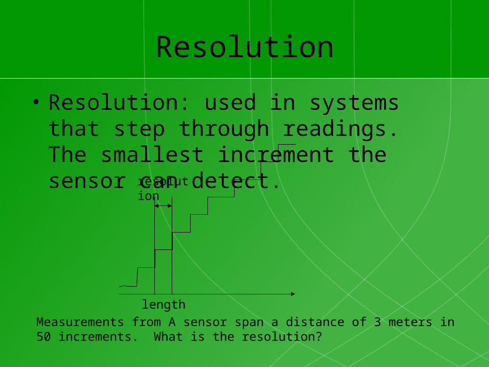
Strain gauges• Strain gauges measure stress-strain in a material by
measuring the resistance in a small piece of wire

• The resistance of a wire is a function of the length, width and thickness. When the wire is stretched, these parameters will change.
• We relate the change in resistance to strain/stress
Wheatstone bridge
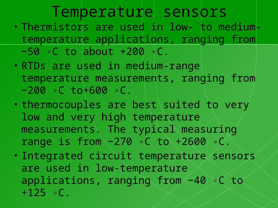
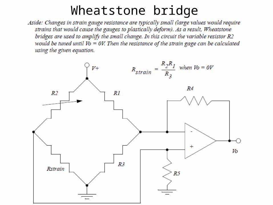
Temperature sensors• Thermistors are used in low- to medium-
temperature applications, ranging from −50 ◦C to about +200 ◦C.
• RTDs are used in medium-range temperature measurements, ranging from −200 ◦C to+600 ◦C.
• thermocouples are best suited to very low and very high temperature measurements. The typical measuring range is from −270 ◦C to +2600 ◦C.
• Integrated circuit temperature sensors are used in low-temperature applications, ranging from −40 ◦C to +125 ◦C.
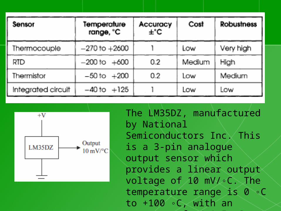
The LM35DZ, manufactured by National Semiconductors Inc. This is a 3-pin analogue output sensor which provides a linear output voltage of 10 mV/◦C. The temperature range is 0 ◦C to +100 ◦C, with an accuracy of +/-1.5 ◦C.

Thermister• Thermistors are non-linear devices, their resistance
will decrease with an increase in temperature.• They are constructed from metal oxide
semiconductors

Thermister instrumentation circuit

Thermocouple• Thermocouples use a junction of dissimilar• metals to generate a voltage proportional to
temperature• The basic calculations for thermocouples
provides the measured voltage using a reference temperature and a constant specific to the device

Equation characterizing a thermocouple

Thermocouple classes
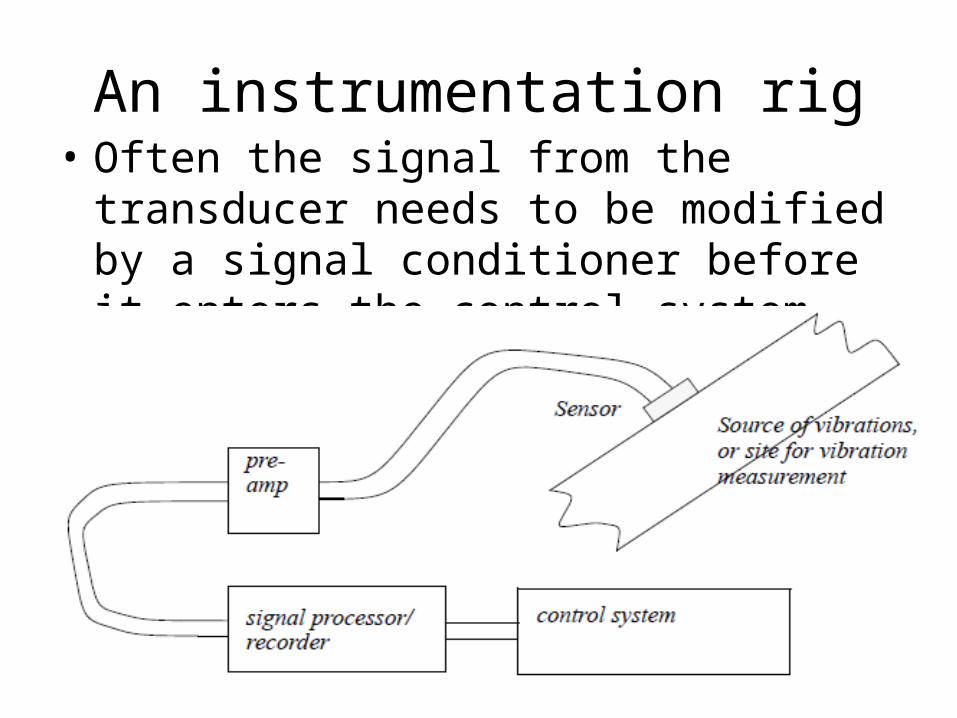
An instrumentation rig• Often the signal from the transducer needs to
be modified by a signal conditioner before it enters the control system

Signal conditioning• Signals from transducers are typically too small to be
read by a normal analogue input card or a MCU• We often use signal conditioning to obtain a signal of
suitable size and format for the Analogue to digital process
• Signal conditioners often contain amplifier circuits.• There are many many different amplification circuits
that use operational amplifiers.• Instrumentation amplifier circuits often have some
capacity to change the gain and offset.• What is important is that you know what the common
ones are, how they are used and how to derive the gain for the amplifier circuit
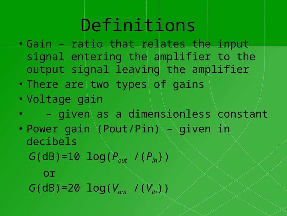
Definitions • Gain – ratio that relates the input signal
entering the amplifier to the output signal leaving the amplifier
• There are two types of gains • Voltage gain • – given as a dimensionless constant• Power gain (Pout/Pin) – given in decibels G(dB)=10 log(Pout /(Pin))
or G(dB)=20 log(Vout /(Vin))

Offset
• The offset in an amplifier circuit is obtained by changing the value of a resistor. This adds a linear value to the output of the amplifier

Inverting amplifier
• where the gain

Non inverting amplifier
𝑉 𝑜𝑢𝑡=𝑉 𝑖𝑛(1+𝑅2
𝑅1)

Voltage follower
𝑉 𝑜𝑢𝑡=𝑉 𝑖𝑛

Summing amplifier
• The summing amplifier produces an inverted output

Single ended signal amplifier• Inverting amplifier with adjustable gain and
offset

Differential voltage amplifier
Under the condition that the Rf/R1 = Rg/R2, the output expression becomes =-) where is the differential gain of the circuit
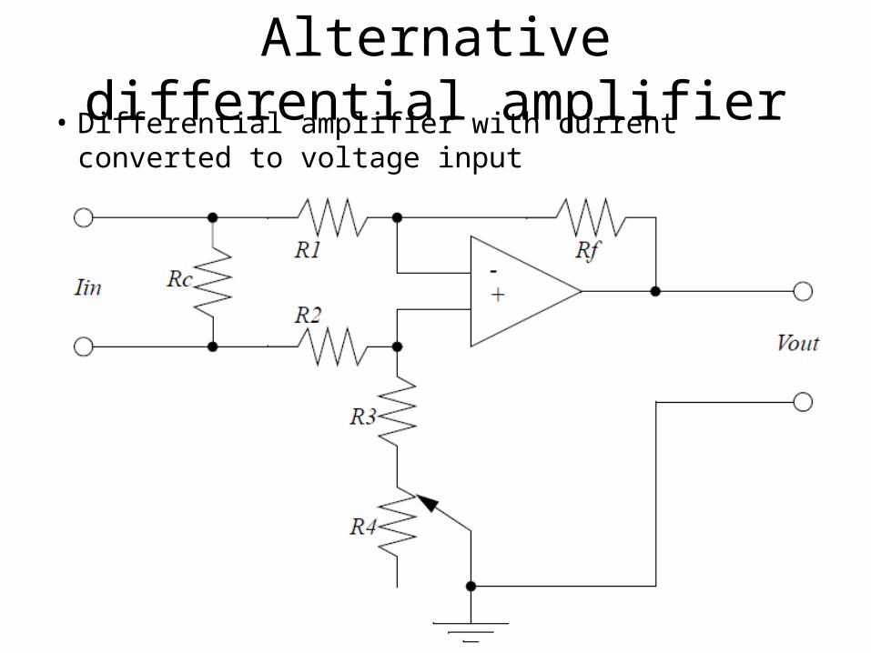
Alternative differential amplifier• Differential amplifier with current converted to voltage input
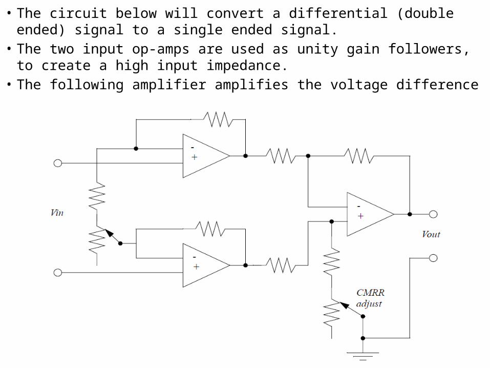
• The circuit below will convert a differential (double ended) signal to a single ended signal.
• The two input op-amps are used as unity gain followers, to create a high input impedance.
• The following amplifier amplifies the voltage difference
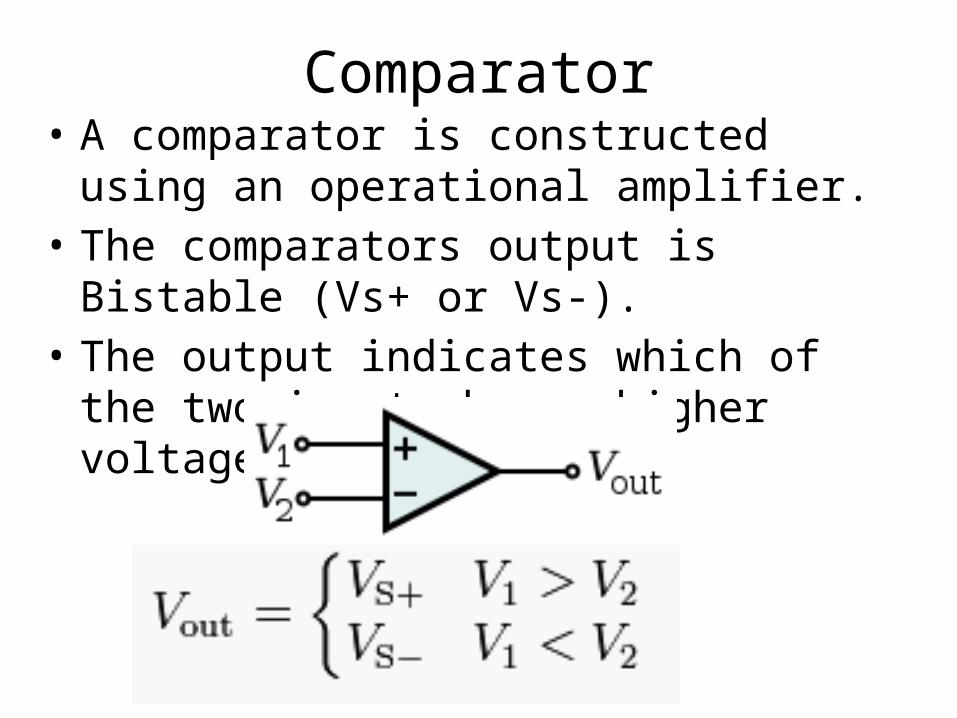
Comparator• A comparator is constructed using an
operational amplifier.• The comparators output is Bistable (Vs+ or Vs-).• The output indicates which of the two inputs
has a higher voltage.