TOP TRACK HINGE SET TOP PIVOT 4 WHEEL HANGER BOTTOM …
4
TOP PIVOT BOTTOM PIVOT 4 WHEEL HANGER BOTTOM GUIDE (optional) Max panel weight 60kg Please read these instructions fully before installation. A A A A A A B B B B B B C C C C C C C A D D D D D D D B E E E E E E F G G G G G G G G G F F F or or or Minimum 120mm based on a minimum door thickness of 35mm 75mm Door to head gap Minimum 15mm Maximum 20mm Door stop applied where necessary. (See section 12) 38mm outside track height 24.6mm outside track height 23mm outside track width 38mm outside track width A B 1 2 15mm 15mm 51mm 5 4 1 2 3 3 4 5 TOP PIVOT 10-69-100-TP TOP PIVOT 10-69-100-TP BOTTOM PIVOT 10-69-100-RBP BOTTOM PIVOT 10-69-100-RBP BOTTOM GUIDE (optional) 10-69-100-BG For use when optional bottom track is installed. BOTTOM TRACK (optional) 4 WHEEL HANGER 10-69-460-TW TOP TRACK HINGE HANDLE SET (optional) 60-320-SS HINGE SET 60-300-SS Top Pivot Block (1) Clamp Plate (2) Clamp Cap Screws (3) Locking Nut (4) Adjustment bolt (5) Interior Folding Door System - Fitting Instructions Components Depending on your chosen door configuration the quantities of each component will vary. OPTIONS Head preparation Prepare the head according to the dimensions shown below. NOTE: Dimensions shown in blue for joinery section sizes are suggestions only. Bottom track (optional) If using a bottom track it should be recessed into the floor and fixed with either adhesive or screws. The following measurements should be observed. The bottom track should be aligned central to the top track. Typical hardware configurations HINGE SET HINGE HANDLE SET (optional) FLUSH BOLT (optional) Minimum 40mm Jamb Cut the bottom track to allow a minimum gap of 40mm between the end of the bottom track and the centre line of any bottom pivots. If there is a pivot set at the opposite end then repeat the same procedure there. Measure 51mm from the jamb at each pivot location and drill a 15mm diameter hole 15mm deep in the floor. Remove any dust and insert the nylon bottom pivot bush. Fix bush to substrate with suitable adhesive. • MAX DOOR WEIGHT 60kg • MAX LEAF WIDTH 900mm • MAX LEAF HEIGHT 3000mm • MINIMUM DOOR THICKNESS 35mm Suitable for residential and light commercial pivot folding partitions, with all panels of equal width. Panels can fold to one or both sides of the opening. To cover any width opening, any number of folding units can be used. 4 doors folding one way 3 doors folding one way with an access door
Transcript of TOP TRACK HINGE SET TOP PIVOT 4 WHEEL HANGER BOTTOM …
TOP PIVOT
BOTTOM PIVOT
4 WHEEL HANGERBOTTOM GUIDE (optional)
Max panel weight
60kgPlease read these instructions fully before installation.
A
A
A
A A
A
B
B
B
B B
B
C
C
C
C
C
C
C
A
D
D
D
D
D
D
D
B
E
EE
E
E
E
FG
G
G G
G
G G
G
G
F
F
For
or
or
Minimum 120mm based on a minimum door thickness of 35mm
75m
m
Door to head gapMinimum 15mmMaximum 20mm
Door stop applied where necessary.(See section 12)
38m
m o
utsi
detra
ck h
eigh
t
24.6
mm
out
side
track
hei
ght
23mm outside track width
38mm outside track width
A
B 1 2
15mm
15mm
51mm
5
4
1
2
33
4
5
TOP PIVOT
BOTTOM PIVOT BOTTOM GUIDE (optional)
FOUR WHEEL TROLLEY
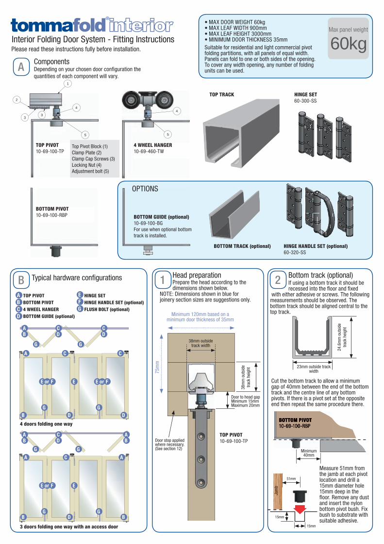
TOP PIVOT 10-69-100-TP
TOP PIVOT 10-69-100-TP
BOTTOM PIVOT 10-69-100-RBP
BOTTOM PIVOT 10-69-100-RBP
BOTTOM GUIDE (optional) 10-69-100-BGFor use when optional bottom track is installed.
BOTTOM TRACK (optional)
4 WHEEL HANGER10-69-460-TW
TOP TRACK
HINGE HANDLE SET (optional)60-320-SS
HINGE SET60-300-SS
Top Pivot Block (1)Clamp Plate (2) Clamp Cap Screws (3)Locking Nut (4) Adjustment bolt (5)
Interior Folding Door System - Fitting Instructions
ComponentsDepending on your chosen door configuration the quantities of each component will vary.
OPTIONS
Head preparationPrepare the head according to the dimensions shown below.
NOTE: Dimensions shown in blue for joinery section sizes are suggestions only.
Bottom track (optional)If using a bottom track it should be recessed into the floor and fixed
with either adhesive or screws. The following measurements should be observed. The bottom track should be aligned central to the top track.
Typical hardware configurations
HINGE SETHINGE HANDLE SET (optional)FLUSH BOLT (optional)
BOTTOM PIVOT10-69-100-RBP
5
4
1
2
33
4
5
TOP PIVOT
BOTTOM PIVOT BOTTOM GUIDE (optional)
FOUR WHEEL TROLLEY
Minimum40mm
Jam
b
Cut the bottom track to allow a minimum gap of 40mm between the end of the bottom track and the centre line of any bottom pivots. If there is a pivot set at the opposite end then repeat the same procedure there.
Measure 51mm from the jamb at each pivot location and drill a 15mm diameter hole 15mm deep in the floor. Remove any dust and insert the nylon bottom pivot bush. Fix bush to substrate with suitable adhesive.
• MAX DOOR WEIGHT 60kg • MAX LEAF WIDTH 900mm• MAX LEAF HEIGHT 3000mm • MINIMUM DOOR THICKNESS 35mmSuitable for residential and light commercial pivot folding partitions, with all panels of equal width.Panels can fold to one or both sides of the opening. To cover any width opening, any number of folding units can be used.
4 doors folding one way
3 doors folding one way with an access door
3
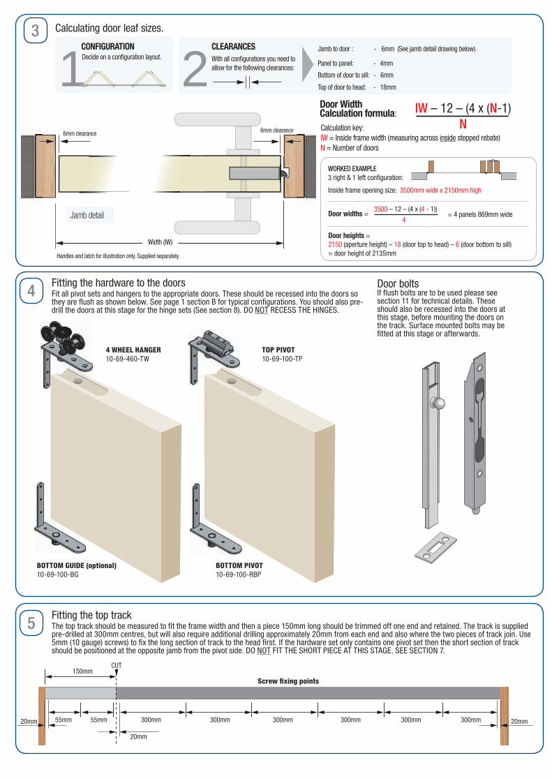
Bottom of door to sill: - 6mm
Top of door to head: - 18mm
Panel to panel: - 4mm
Jamb to door : - 6mm (See jamb detail drawing below).
WORKED EXAMPLE3 right & 1 left configuration:
Inside frame opening size: 3500mm wide x 2150mm high
3500 – 12 – (4 x (4 - 1))
4
Calculation key: IW = Inside frame width (measuring across inside stepped rebate) N = Number of doors
Jamb detail
6mm clearance
Handles and latch for illustration only. Supplied separately.
6mm clearance
Calculating door leaf sizes.
1 2Decide on a configuration layout. With all configurations you need to allow for the following clearances:
CLEARANCESCONFIGURATION
4L 3R4L 3R
2R
2R 1L2R 1L
2L 1R2L 1R
2L 2R2L 2R
3R3R
3R 1L3R 1L
3R 2L3R 2L
3L3L
3L 1R3L 1R
3L 2R3L 2R
3L 3R3L 3R
2L2L
4R 3L4R 3L
4L4L
4R4R
4R 1L4R 1L
4R 2L4R 2L
5R5R
5R 1L5R 1L
5R 3L5R 3L
5L 5R5L 5R
4L 2R4L 2R
4L 1R4L 1R
4L 4R4L 4R
5R 2L5R 2L
5R 4L5R 4L
5L5L
5L 1R5L 1R
5L 3R5L 3R
5L 2R5L 2R
5L 4R5L 4R
use this version when redesigning catalogue
IW – 12 – (4 x (N-1)
N
Door WidthCalculation formula:
Door widths =
Door heights = 2150 (aperture height) – 18 (door top to head) – 6 (door bottom to sill)= door height of 2135mm
= 4 panels 869mm wide
Width (IW)
Fitting the hardware to the doorsFit all pivot sets and hangers to the appropriate doors. These should be recessed into the doors so they are flush as shown below. See page 1 section B for typical configurations. You should also pre-drill the doors at this stage for the hinge sets (See section 8). DO NOT RECESS THE HINGES.
Fitting the top trackThe top track should be measured to fit the frame width and then a piece 150mm long should be trimmed off one end and retained. The track is supplied pre-drilled at 300mm centres, but will also require additional drilling approximately 20mm from each end and also where the two pieces of track join. Use 5mm (10 gauge) screws) to fix the long section of track to the head first. If the hardware set only contains one pivot set then the short section of track should be positioned at the opposite jamb from the pivot side. DO NOT FIT THE SHORT PIECE AT THIS STAGE. SEE SECTION 7.
Door boltsIf flush bolts are to be used please see section 11 for technical details. These should also be recessed into the doors at this stage, before mounting the doors on the track. Surface mounted bolts may be fitted at this stage or afterwards.
4
5
150mmCUT
Track access section for hardware loading
150mm
Track access section for hardware loading
150mm
300mm55mm20mm 55mm 300mm 300mm 300mm 300mm 300mm
CUT
20mm
20mm
15
160
5
2
17
8
Straight keep
Angledkeep1.5
16 23
13
131
29
23
1513
1.5
Angledkeep
TOP PIVOT 10-69-100-TP
BOTTOM PIVOT 10-69-100-RBP
BOTTOM GUIDE (optional) 10-69-100-BG
4 WHEEL HANGER10-69-460-TW
Screw fixing points
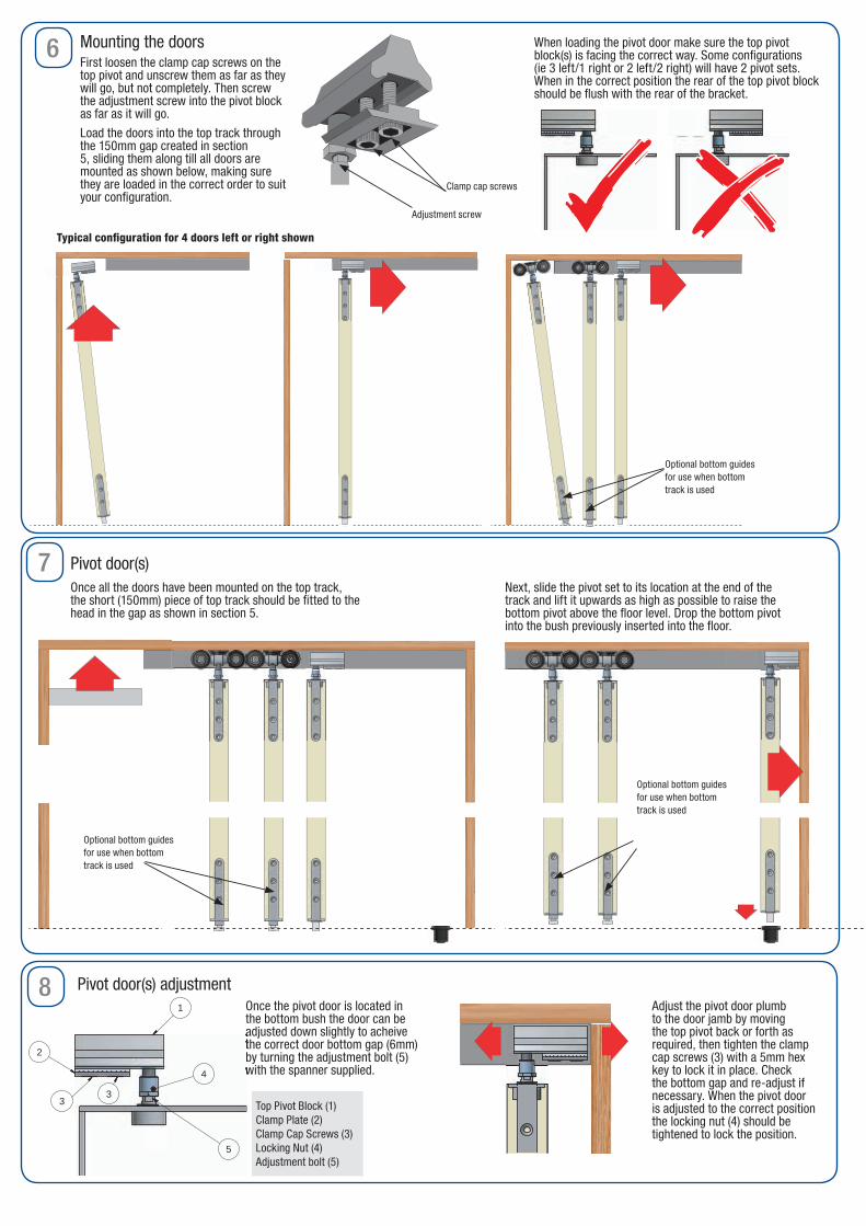
6 Mounting the doors
Pivot door(s)
First loosen the clamp cap screws on the top pivot and unscrew them as far as they will go, but not completely. Then screw the adjustment screw into the pivot block as far as it will go.
Load the doors into the top track through the 150mm gap created in section 5, sliding them along till all doors are mounted as shown below, making sure they are loaded in the correct order to suit your configuration.
Once all the doors have been mounted on the top track, the short (150mm) piece of top track should be fitted to the head in the gap as shown in section 5.
Next, slide the pivot set to its location at the end of the track and lift it upwards as high as possible to raise the bottom pivot above the floor level. Drop the bottom pivot into the bush previously inserted into the floor.
When loading the pivot door make sure the top pivot block(s) is facing the correct way. Some configurations (ie 3 left/1 right or 2 left/2 right) will have 2 pivot sets. When in the correct position the rear of the top pivot block should be flush with the rear of the bracket.
Typical configuration for 4 doors left or right shown
7
Clamp cap screws
Adjustment screw
Optional bottom guides for use when bottom track is used
Optional bottom guides for use when bottom track is used
Optional bottom guides for use when bottom track is used
8Once the pivot door is located in the bottom bush the door can be adjusted down slightly to acheive the correct door bottom gap (6mm) by turning the adjustment bolt (5) with the spanner supplied.
Adjust the pivot door plumb to the door jamb by moving the top pivot back or forth as required, then tighten the clamp cap screws (3) with a 5mm hex key to lock it in place. Check the bottom gap and re-adjust if necessary. When the pivot door is adjusted to the correct position the locking nut (4) should be tightened to lock the position.
Pivot door(s) adjustment
adjusted down slightly to acheive the correct door bottom gap (6mm) by turning the adjustment bolt (5) with the spanner supplied.
5
4
1
2
33
4
5
TOP PIVOT
BOTTOM PIVOT BOTTOM GUIDE (optional)
FOUR WHEEL TROLLEY
Top Pivot Block (1)Clamp Plate (2) Clamp Cap Screws (3)Locking Nut (4) Adjustment bolt (5)
9 10
11
12
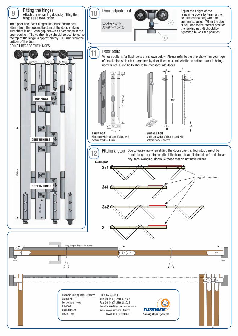
Fitting the hinges
The upper and lower hinges should be positioned 85mm from the top and bottom of the door, making sure there is an 16mm gap between doors when in the open position. The centre hinge should be positioned so the top of the hinge is approximately 1060mm from the bottom of the door.DO NOT RECESS THE HINGES.
Adjust the height of the remaining doors by turning the adjustment bolt (5) with the spanner supplied. When the door is adjusted to the correct position the locking nut (4) should be tightened to lock the position.
Min
85m
m
1060
mm
Min
85m
m
Gap 16mm Gap 16mm Gap 16mm
Door adjustment
Door bolts
Fitting a stop
5
4
1
2
33
4
5
TOP PIVOT
BOTTOM PIVOT BOTTOM GUIDE (optional)
FOUR WHEEL TROLLEY
Attach the remaining doors by fitting the hinges as shown below.
15
160
5
2
17
8
Straight keep
Angledkeep1.5
16 23
13
131
29
23
1513
1.5
Angledkeep
15
160
5
2
17
8
Straight keep
Angledkeep1.5
16 23
13
131
29
23
1513
1.5
Angledkeep
16
8
13
13
16
250/
200/
150
41
Suggested door stop
Sliding Door Systems
Runners Sliding Door SystemsSignal HillLenborough RoadGawcottBuckinghamMK18 4BU
UK & Europe Sales: Tel: 00 44 (0)1280 822288Fax: 00 44 (0)1280 813024Email: [email protected]: www.runners-uk.com www.tommafold.com
length depending on door width
20mm
20mm
20mm
length depending on door width
20mm
20mm
20mm
Various options for flush bolts are shown below. Please refer to the one shown for your type of installation which is determined by door thickness and whether a bottom track is being used or not. Flush bolts should be recessed into doors.
Locking Nut (4) Adjustment bolt (5)
TOP HINGE
CENTRE HINGE
BOTTOM HINGE
Flush boltMinimum width of door if used with bottom track = 45mm.
Surface boltMinimum width of door if used with bottom track = 35mm.
Due to outswing when sliding the doors open, a door stop cannot be fitted along the entire length of the frame head. It should be fitted above any ‘free swinging’ doors, ie those that do not have rollers
Examples
3+1
2+1
3+2
3