Tooth defect detection in planetary gears by the current ...
25
Comptes Rendus Mécanique Safa Boudhraa, Alfonso Fernandez del Rincon, Fakher Chaari, Mohamed Haddar and Fernando Viadero Tooth defect detection in planetary gears by the current signature analysis: numerical modelling and experimental measurements Volume 349, issue 2 (2021), p. 275-298 <https://doi.org/10.5802/crmeca.84> © Académie des sciences, Paris and the authors, 2021. Some rights reserved. This article is licensed under the Creative Commons Attribution 4.0 International License. http://creativecommons.org/licenses/by/4.0/ Les Comptes Rendus. Mécanique sont membres du Centre Mersenne pour l’édition scientifique ouverte www.centre-mersenne.org
Transcript of Tooth defect detection in planetary gears by the current ...

Comptes Rendus
Mécanique
Safa Boudhraa, Alfonso Fernandez del Rincon, Fakher Chaari,Mohamed Haddar and Fernando Viadero
Tooth defect detection in planetary gears by the current signatureanalysis: numerical modelling and experimental measurements
Volume 349, issue 2 (2021), p. 275-298
<https://doi.org/10.5802/crmeca.84>
© Académie des sciences, Paris and the authors, 2021.Some rights reserved.
This article is licensed under theCreative Commons Attribution 4.0 International License.http://creativecommons.org/licenses/by/4.0/
Les Comptes Rendus. Mécanique sont membres duCentre Mersenne pour l’édition scientifique ouverte
www.centre-mersenne.org

Comptes RendusMécanique2021, 349, n 2, p. 275-298https://doi.org/10.5802/crmeca.84
Short paper / Note
Tooth defect detection in planetary gears by
the current signature analysis: numerical
modelling and experimental measurements
Safa Boudhraa a, b, Alfonso Fernandez del Rincon a, Fakher Chaari ∗, b,Mohamed Haddar b and Fernando Viadero a
a Department of Structural and Mechanical Engineering, Faculty of Industrial andTelecommunications Engineering, University of Cantabria, Avda de los Castros s/n39005, Santander, Spainb Laboratory of Mechanics, Modelling and Production (LA2MP), National School ofEngineers of Sfax, BP1173, 3038 Sfax, Tunisia
E-mails: [email protected] (S. Boudhraa),[email protected] (A. Fernandez del Rincon), [email protected](F. Chaari), [email protected] (M. Haddar), [email protected](F. Viadero)
Abstract. Monitoring transmission systems is a huge scientific focus to prevent any anomaly and malfunc-tioning damaging the system. Several methods were used to investigate the gears behaviour and mainly itsstate. And until the last century, vibrations signals were the most performing technique in this field. However,nowadays, other alternatives are considered more accurate and accessible such as controlling the motor cur-rent signals to study the behaviour of the mechanical system. Within this context, this paper aims to studythe electromechanical interaction between a double stage of planetary gearboxes driven by an asynchronousmachine. The model used is based on a Park transformation for modelling the asynchronous machine and atorsional model to describe the dynamic behaviour of the double-stage planetary gearbox. Through this ap-proach, the numerical simulations illustrate the impact of the tooth gear defect on the signature of the motorcurrent. The results obtained from the simulations will be presented in the time domain and the frequencydomain using the fast Fourier transform and the Hanning window to highlight the mechanical frequencies inthe phase current spectrum. This work will be distinguished by validating the numerical results using exper-imental measurements, which will be displayed in order to justify the sensitivity of the model developed.
Keywords. Asynchronous motor, Experimental measurements, Gears defects, Motor current, Park transfor-mation, Planetary gears.
Manuscript received 22nd March 2021, revised 21st April 2021, accepted 28th April 2021.
∗Corresponding author.
ISSN (electronic) : 1873-7234 https://comptes-rendus.academie-sciences.fr/mecanique/
276 Safa Boudhraa et al.
1. Introduction
Planetary gearboxes have been used in different industrial domains especially in applicationsthat recommend large torque transmission. Due to its spatial configuration, planetary transmis-sions are complicated to model, but the importance of these gear systems in aerospace and en-ergy generation applications makes the effort worth it. Despite its enormous use, durability andcondition monitoring of these systems are still a major scientific trend also an industrial focus.Gears are exposed to several types of defects. Those defects are divided into two main familiesas stated in Chaari et al. [1]; geometry defects, which concerns manufacturing and assembly de-fects, and teeth defects, that attack the system, like pitting, cracks, or breakages, etc. Thus, manyresearchers had worked on evaluating gears state by different techniques based on nondestruc-tive tests that aim to provide early detection of any anomalies in the system. Until the beginningof the last century, studying the vibration signals of the rotating machinery has been the mostperforming tool to evaluate the dynamic behaviour and to detect the presence of any mechanicaldefect.
In order to study the dynamic behaviour of these gears in the presence of tooth pitting andcracking, Chaari et al. [2], had worked on modelling defected planetary gearboxes. Likewise,Fernandez et al. [3, 4] had developed a model that studies the interaction between different pairsof teeth in contact. Li et al. [5] had used an extraction method using both the Empirical ModeDecomposition and Autocorrelation Local Cepstrum to detect fault diagnosis of sophisticatedmultistage gearbox.
The impact of tooth defect generates a torque variation which is manifested in a significantmodification of contact ratio. Within the same context, Qinkai et al. [6] had also investigatedthe localization of tooth breakage on a wind turbine planetary gear system, considering themanufacturing errors. Indeed, the severity of the impact depends on the type, placement, andsize of the defect. Therefore, each defect has different signature that will lead to detect andidentify it by analysing the output signals. The tooth defect is characterized in the vibrationsignal by its key frequency. Through the frequency spectrum, the vibration signals of a single-stage planetary gearbox provide an overview of the teeth defect. This correlation is identifiedand explained by a numerical model and experimental investigations developed by Qiang andQinghua [7]. Moreover, vibration signals have been the key of diagnosing the gears state inhelicopters, not only in detecting gears defects but also in studying its impact on the behaviourof the system and its natural frequencies [8–10].
However, the use of this technique has several limitations, such as the sensitivity of the sensorsused to the operating conditions. These sensors used can enhance the appearance of significantnoise in the signals due to perturbations. Also, for complicated rotating machineries it is verydifficult to get access to implement the sensors. Therefore, the industry is interested in a moreaccurate technique that provides a global overview about the system behaviour with least cost.In this framework, innovative engineering is oriented to the multi-domain interaction that aimsto control the mechanical systems by involving different physical phenomena, such as the motorcurrent signature analysis (MCSA), which has been one of the most used techniques is this field.
And so forth, Kar et al. [11] had worked on investigating other techniques to early defectsdetection. The paper was based on a comparative study between vibrations and motor currentintensity in the presence of tooth defect. The MCSA was used also to evaluate the influence ofthe electromagnetic effect on the natural vibration characteristics of the gearbox in the work ofYi et al. [12].
Investigating the motor’s behaviour was used in several studies to monitor the mechanical sys-tem, detecting defects. This Proposal was highlighted by the work developed by Balan et al. [13]studying the impact of the unbalance seen in the motor’s component on the motor current signal.
C. R. Mécanique — 2021, 349, n 2, 275-298

Safa Boudhraa et al. 277
The use of the current signal to investigate the gearbox state is considered more accurate giventhe accessibility for different operating conditions and complex systems. This is one additionaladvantage comparing with the vibration signals, since in the stator current, the modulationsproduced by the planet motion do not appear [14], which makes the spectrum more significant.Different research papers [14, 15] had proved the sensitivity of this method not only to detectthe state of the system but also to localize and identify the defect. Nandi et al. [16, 17] had usedthe motor current signal analysis MCSA to show that the appearance of the static and dynamicair gap eccentricity simultaneously is seen in the amplitude modulation of the stator current.Kia [18] had develop the idea of using the current of the driving machine to detect a mechanicalsystem defect. In fact, this development is based on a fundamental study of the effect of the tor-sional vibration for two mass–spring systems in the stator current signal [19, 20]. It had showedthat for two different joints inertia–mass systems, the source of torque oscillation is related to asingle torsional vibrations frequency.
For the electrical part, the modelling of the asynchronous machine was done in different stud-ies by various approaches such as analytical, semi-analytical, or finite element modelling. Thechoice of the approach depends on whether the need of it or mainly the operating conditionswhich define the hypothesis of modelling. One of the basic method used in the analytical mod-elling is the Park transformation [21], that transforms a tri-phased motor, to an equivalent two-phase machine called a d-q model. Even though finite element methods are the most used nowa-days for simple problems and controlling the electrical machines, the Park transformation is rec-ommended for rapidly resolving situations in steady state operating conditions. Few researchersworked on the planetary gears monitoring using the MSCA, Ottewill et al. [22] had investigatedthe impact of the tooth defect in epicyclic gearboxes on the current signals using numerical mod-elling pursued by experimental validation.
The importance of using the motor current signature analysis is highlighted mainly in the ac-cessibility to the information through the driving system. Electric machine current signal analy-sis provides an alternative technique for planetary gearbox fault diagnosis. The faults generatedin the mechanical system led to changes in electric current intensity because of mechanical–magnetic–electric interactions, and hence electric current signals contain rich information aboutplanetary gearbox health conditions. Goa had demonstrated [23] that the impact of a gear defectis sidebands of the supply frequency of the motor. Planetary gearbox faults result in input torqueoscillations, leading to both amplitude modulation and frequency modulation (AM–FM) effectson stator current signals.
Besides the accessibility, this technique is mainly used in power stations to avoid systemdamage. Also, online fault monitoring can be done without shutdown the motor [24].
The study presented in this paper extends the approach of studying the electromechanicalinteraction’s ability to monitor the mechanical system. This work is going to be structured in thepaper as follows. Section 2 is dedicated to the theoretical development of an electromechanicalsystem composed of a planetary gearbox and an induction motor. In Section 3, the experimentaltestbench is described, composed of a Siemens induction motor and a back-to-back planetarygearbox. In Section 4, the numerical model developed in Section 2 will be adopted to simulatethe experimental rig. Finally, the last section highlights the accuracy of the current signals ininvestigating the state of the gears in a double-stage planetary gearbox. And later, experimentalmeasurements were taken in order to validate the sensitivity of the model. The real contributionin this work is justifying the numerical approach by experiments. Lastly, some conclusions arepresented.
C. R. Mécanique — 2021, 349, n 2, 275-298

278 Safa Boudhraa et al.
Figure 1. A torsional model of a double-stage planetary gearbox.
2. Theoretical formulation
The electromechanical model is composed of three parts:Starting from the mechanical model of planetary gears, this model is based mainly on the
motion expression that illustrates the dynamic behaviour of the system, considering only thetorsional degree of freedom. The second part will be devoted to the model of the asynchronousmotor using the Park transformation that aims to transfer the three-phased motor to an equiv-alent circuit. Finally, in the last part, a global electromechanical system based on both previousmodels is presented. The coupling terms between the electrical part and the mechanical systemare due to the electromechanical torque coming from the motor and the vibration’s responses ofthe gearboxes to the motor.
2.1. Mechanical model
The mechanical system developed in this study is a planetary gear set. In order to simplifythe model, only torsional degrees of freedom were considered, and therefore only the torsionalstiffness will be involved in the model, Figure 1. Modelling the planetary gears used is based onthe development of Lin and Parker [25] and its dynamic model. So, the model seen in Figure 1presents (n +3) degrees of freedom each gearbox, where n is the planets number (given 3 in thiscase).
The equation of motion for the mechanical system is expressed as follows:
M q +C q + (K (t )+Kc )q = F (t ), (1)
where F (t ) and q(t ) are external force and displacement vector, respectively. M represents thediagonal mass matrix
M = diag(mc +N mp ,mr ,ms ,m1,m2,m3) (2)
and mi = Ii /ri , where Ii refers to the inertia of each component and ri is the base radius of thecomponent i . Finally, C refers to the damping matrix, taken as a Rayleigh damping.
The mesh stiffness of the system is given by the matrix both K (t ) (3).In each set of gears, the sun and the ring were connected to the three planets via the mesh
stiffness given by Ki n j , Ki j , where i ∈ s,r , where s refers to the sun and r to the ring, n ∈ t ,r
C. R. Mécanique — 2021, 349, n 2, 275-298

Safa Boudhraa et al. 279
(r refers to the reaction gearbox, t refers to test gearbox) and j presents the number of planets,j ∈ 1,2,3. The mesh stiffness is usually assumed as one linear spring as seen in Figure 1, actingon the line of action. Thus, the possibility of considering one stiffness for each contact [26].
K (t ) =
3∑i=1
(Ksi (t )+Kr i (t )) −3∑
i=1Kr i (t ) −
3∑i=1
Kr i (t ) Kr 1(t )−Ks1(t ) Kr 2(t )−Ks2(t ) Kr 3(t )−Ks3(t )
−3∑
i=1Kr i (t )
3∑i=1
Kr i (t ) 0 −Kr 1(t ) −Kr 2(t ) −Kr 3(t )
−3∑
i=1Ksi (t ) 0
3∑i=1
Ksi (t ) Ks1(t ) Ks2(t ) Ks3(t )
Kr 1(t )−Ks1(t ) −Ks3(t ) Ks1(t ) Ks1(t )+Kr 1(t ) 0 0Kr 2(t )−Ks2(t ) −Kr 2(t ) Ks2(t ) 0 Ks2(t )+Kr 2(t ) 0Kr 3(t )−Ks3(t ) −Kr 3(t ) Ks3(t ) 0 0 Ks3(t )+Kr 3(t )
.
(3)
2.2. Electrical model
Modelling the electrical machine has been a tool whether to study the machine state or toensure the physical coupling between motor and any mechanical systems. The model useddepends on the application [27]. Thus, the objective of this study is to investigate the state of themechanical system. For this reason, it was decided to work with a Park transformation since it isan analytical approach with settings easily identifiable [28]. Park transformation is an analyticalmethod that aims to transform a three-phased machine into a bi-directional, maintaining thephysical phenomena. Since this method recommends theoretical developments of equationsdescribing the electromagnetic response of an asynchronous motor, it is necessary to make thefollowing assumptions to simplify the complexity of the system.
• The saturation is neglected: the own and mutual inductances are independent of thecurrents flowing in the different windings.
• Hysteresis and eddy currents are not considered in the magnetic parts because it isassumed that the magnetic circuit is perfectly laminated.
• The notches are supposed to be infinitely thin in order to neglect the notches effect.• Magnetomotive forces are sinusoidally distributed in the air gap and are assumed uni-
form; there is symmetry with respect to the magnetic axis of the windings.
The choice of the d q0 framework related to the rotating system depends on the objective of thestudy [29]. The change from a three-phased machine to a bi-phased was ensured by the matrix.
Td q0 =√
2
3
cosθ cos
(θ− 2π
3
)cos
(θ+ 2π
3
)−sin(θ) −sin
(θ− 2π
3
)−sin
(θ+ 2π
3
)1p2
1p2
1p2
, (4)
where ω= dθ/dt .The relation ensuring the interaction between the magnetic field and the electric circuit is
given by the Law of Faraday.
vi j = R j ii j +dψi j
dt, (5)
where R j : resistance of j phase; j : stator, rotor; i : coiling (a, b, c).ψi j : the magnetic flux of j phase.ii j : the current of the j phase.
C. R. Mécanique — 2021, 349, n 2, 275-298

280 Safa Boudhraa et al.
The asynchronous motor case is squirrel cage motor, which explains the following expression
var = vbr = vcr = 0. (6)
The relations between the magnetic flux ψ and the current in each phase coiling, noted ii j , arepresented by the matrix expression below (7) and (8)
ψas
ψbs
ψcs
=
Las Mas Mr s cosθ Mr s cosθ Mr s cos
(θ+ 2π
3
)Mr s cos
(θ− 2π
3
)Mas Las Mr s cosθ Mr s cos
(θ− 2π
3
)Mr s cosθ Mr s cos
(θ+ 2π
3
)Mas Mas Las Mr s cos
(θ+ 2π
3
)Mr s cos
(θ+ 2π
3
)Mr s cosθ
∗
ias
ibs
ics
iar
ibr
icr
(7)
ψar
ψbr
ψcr
=
Mr s cosθ Mr s cos
(θ− 2π
3
)Mr s cos
(θ+ 2π
3
)Lar Mar Mar
Mr s cos
(θ+ 2π
3
)Mr s cosθ Mr s cos
(θ− 2π
3
)Mar Lar Mar
Mr s cos
(θ− 2π
3
)Mr s cos
(θ+ 2π
3
)Mr s cosθ Mar Mar Lar
∗
ias
ibs
ics
iar
ibr
icr
, (8)
whereMas : mutual inductance between two phases of the statorMar : mutual inductance between two phases of the rotorLas : self-inductance of the statorLar : self-inductance of the rotorMr s : maximum inductance between a stator’s phase and a rotor’s phase.The previous electrical and magnetic expressions are described in the same frame d q .
vd s
vqs
=
[Rs 00 Rs
]id s
iqs
+ d
dt
ψd s
ψqs
+
[0 −ωe
ωe 0
]ψd s
vqs
(9)
vdr
vqr
=
[Rr 00 Rr
]idr
iqr
+ d
dt
ψdr
ψqr
+
[0 −ωr
ωr 0
]ψdr
vqr
(10)
ψd s
ψdr
=
[Ls Lm
Lm Lr
]id s
idr
(11)
ψqs
ψqr
=
[Ls Lm
Lm Lr
]iqs
iqr
. (12)
Supposing Ls = Las −Mas : stator synchronous inductanceLr = Lar −Mar : rotor synchronous inductanceLm = (3/2)Mr s : magnetizing inductance,where ωs = pπ f , ω= pπN /30 and ωr =ω−ωs .The previous analytical development of the three-phased motor had contributed to give a bi-
phased equivalent machine, as presented in Figure 2. The stator current and the rotor magneticflux, written in the same framework had led to the global asynchronous machine model givenby (14).
d
dtX (t ) = [A]X (t )+ [B ]U (t ), (13)
C. R. Mécanique — 2021, 349, n 2, 275-298

Safa Boudhraa et al. 281
Figure 2. The equivalent bi-phased machine obtained from an asynchronous motor.
Table 1. Motor parameters
Parameters ValueRs 9.172 Ω
Rr 5.162 Ω
Ls 0.115 HLr 0.0943 HLm 0.0943 H
where X (t ) the state vector given by
X (t ) = id s iqs ψdr ψqr
T(14)
⇒ d
dt
id s
iqs
ψdr
ψdr
=
e11 e12 ∗ωs e13 e14 ∗ω
e21 ∗ωs e22 e23 ∗ω e24
e31 0 e33 e34 ∗ωr
0 e42 e43 ∗ωr e44
id s
iqs
ψdr
ψdr
+
1
σLs0
01
σLs0 00 0
vd s
vqs
, (15)
where
σ = 1−(
Lm2
Ls Lr
); Tr = Lr
Rr; Ts = Ls
Rs
e11 = e22 =−(
1
σTs+ (1−σ)
σTr
), e33 = e44 =− 1
Tre12 = e34 = 1, e21 = e43 =−1
e13 = e24 = (1−σ)
σTr Lm, e31 = e42 = Lm
Tr
e14 = −e23 = (1−σ)
σLm.
The electrical parameters of the motor are given in the Table 1. The motor’s parameters mainlyused in the simulations (resistance and inductance) were determined by experimental measure-ments through the starter “MICROMASTER”.
2.3. Electromechanical problem
The combination of all the expressions had led to a global electromechanical system (16). Thecoupled state variable vector contains different electrical parameters of the motor (current and
C. R. Mécanique — 2021, 349, n 2, 275-298
282 Safa Boudhraa et al.
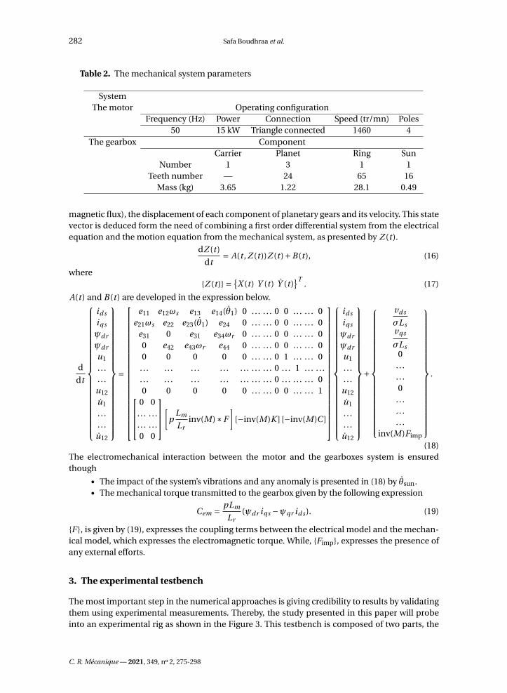
Table 2. The mechanical system parameters
SystemThe motor Operating configuration
Frequency (Hz) Power Connection Speed (tr/mn) Poles50 15 kW Triangle connected 1460 4
The gearbox ComponentCarrier Planet Ring Sun
Number 1 3 1 1Teeth number — 24 65 16
Mass (kg) 3.65 1.22 28.1 0.49
magnetic flux), the displacement of each component of planetary gears and its velocity. This statevector is deduced form the need of combining a first order differential system from the electricalequation and the motion equation from the mechanical system, as presented by Z (t ).
dZ (t )
dt= A(t , Z (t ))Z (t )+B(t ), (16)
whereZ (t ) =
X (t ) Y (t ) Y (t )T
. (17)
A(t ) and B(t ) are developed in the expression below.
d
dt
id s
iqs
ψdr
ψdr
u1
. . .
. . .u12
u1
. . .
. . .u12
=
e11 e12ωs e13 e14(θ1) 0 . . . . . . 0 0 . . . . . . 0e21ωs e22 e23(θ1) e24 0 . . . . . . 0 0 . . . . . . 0
e31 0 e31 e34ωr 0 . . . . . . 0 0 . . . . . . 00 e42 e43ωr e44 0 . . . . . . 0 0 . . . . . . 00 0 0 0 0 . . . . . . 0 1 . . . . . . 0
. . . . . . . . . . . . . . . . . . . . . 0 . . . 1 . . . . . .
. . . . . . . . . . . . . . . . . . . . . 0 . . . . . . . . . 00 0 0 0 0 . . . . . . 0 0 . . . . . . 1
0 0. . . . . .. . . . . .0 0
[p
Lm
Lrinv(M)∗F
][−inv(M)K ] [−inv(M)C ]
id s
iqs
ψdr
ψdr
u1
. . .
. . .u12
u1
. . .
. . .u12
+
vd s
σLsvqs
σLs0
. . .
. . .0
. . .
. . .
. . .inv(M)Fimp
.
(18)The electromechanical interaction between the motor and the gearboxes system is ensuredthough
• The impact of the system’s vibrations and any anomaly is presented in (18) by θsun.• The mechanical torque transmitted to the gearbox given by the following expression
Cem = pLm
Lr(ψdr iqs −ψqr id s ). (19)
F , is given by (19), expresses the coupling terms between the electrical model and the mechan-ical model, which expresses the electromagnetic torque. While, Fimp, expresses the presence ofany external efforts.
3. The experimental testbench
The most important step in the numerical approaches is giving credibility to results by validatingthem using experimental measurements. Thereby, the study presented in this paper will probeinto an experimental rig as shown in the Figure 3. This testbench is composed of two parts, the
C. R. Mécanique — 2021, 349, n 2, 275-298

Safa Boudhraa et al. 283
Figure 3. (a) The test bench, (b) the test gearbox, (c) the external load.
characteristics of which are illustrated in Table 2. The driving part is a three-phased asynchronousmotor controlled by a Siemens inventor. The mechanical part is structured as a back-to-backplanetary gearbox, which is basically composed of two stages of identical planetary gearbox(reaction and test).
Each stage, as shown in the same Figure 3, is composed of an external ring, three planets fixedon a carrier, and a sun, which is the input gear. The configuration of the bench is compacted witha mechanical power circulation for economic energy efficiency. Both gearboxes are connected toeach other through a rigid hollow shaft that holds both carriers and a second one that connectsthe sun of the reaction gearbox to the test sun [30].
C. R. Mécanique — 2021, 349, n 2, 275-298

284 Safa Boudhraa et al.
Figure 4. Back-to-back configuration in the testbench used.
Figure 5. The electric clamp.
The experimental measurements were done for constant speed fixed by fixing the motor inputfrequency maintained in the experiments at 20 Hz (corresponds to 570 rpm: rotating speed).
The configuration of the used test bench is compact with purely mechanical power circulation.For the mechanical power circulation type, input and output shafts of both gearboxes withidentical gear ratios are connected to each other by intermediate shafts and gearboxes.
The sun gears of both planetary gear sets are connected through a common shaft and thecarriers of both planetary gear sets are connected to each other through a rigid hollow shaft. Thissystem builds a closed loop as seen in Figure 4 below.
Moreover, the design of the test bench allows applying external load on the testbench by anarm connected to the reaction gearbox. The load added on the test bench is described by externalmasses or by using a jark as seen in Figure 3(c).
In the experiments, we used 600 N·m load applied.As for the instrumentations, clamp metre of type fluke i200s AC current clamp, sensitivity of
10 mv/A as shown in Figure 5 was mounted around the input wires of the motor to measure thecurrent in each phase of the motor. The clamp was connected to a data acquisition system “LMSSCADAS 316”, controlled by LMS Test Lab, where all the data was registered and archived.
In order to highlight the sensitivity of the numerical model, to detect the tooth defect, we hadintroduced on one of the planets a groove as shown in Figure 6. The cut was done on the lengthof the teeth, with a depth and a width which equals, respectively, to 0.2 mm and 0.3 mm.
4. Numerical simulations
In order to adopt the numerical model developed in Section 2 to the test bench in Section 3,we consider a double-stage planetary gears as show in Figure 7. The mesh stiffness of the global
C. R. Mécanique — 2021, 349, n 2, 275-298

Safa Boudhraa et al. 285
Figure 6. The planet defect.
system is given by K (t ) = diag(Kt ,Kr ), where t describes the test gear set and r the reaction set.For the stiffness, connections between both gearboxes were simulated to linear springs in theKc coupling stiffness matrix. As indicated above, the connection between the test gearbox andthe reaction gearbox is done through two shafts and this connection is assured in the numericalmodel by the matrix below.
As seen, Figure 7 illustrates a numerical schema of the test bench and clarify the connectionmatrix (20) between both gearboxes and all the corresponding parameters are presented in detailin Table 3. The connecting shafts are modelled by torsional stiffness Ks and Kc , where Ks is givento the stiffness of the shaft connecting the suns and Kc for the hollow shaft connecting carriers.For this testbench the reaction ring is considered free, its torsional stiffness Kr r u equals to zero,although, the test ring is not completely clamped so a high torsional stiffness Kr tu is given.
Kc =
kc 0 0 0 0 0 −kc 0 0 0 0 00 kr tu 0 0 0 0 0 0 0 0 0 00 0 ks 0 0 0 0 0 −ks 0 0 00 0 0 0 0 0 0 0 0 0 0 00 0 0 0 0 0 0 0 0 0 0 00 0 0 0 0 0 0 0 0 0 0 0
−kc 0 0 0 0 0 kc 0 0 0 0 00 0 0 0 0 0 0 kr tu 0 0 0 00 0 0 0 0 0 0 0 ks 0 0 00 0 −ks 0 0 0 0 0 0 0 0 00 0 0 0 0 0 0 0 0 0 0 00 0 0 0 0 0 0 0 0 0 0 0
. (20)
In order to highlight the sensitivity of the model used to different perturbations, some toothdefects would be introduced in the coming work. Chaari et al. [1] had proved that the presence of
C. R. Mécanique — 2021, 349, n 2, 275-298

286 Safa Boudhraa et al.
Figure 7. Numerical model of the test bench.
Table 3. The simulations parameters
Input frequency 50 HzSun Planet Ring Carrier
Moment of inertia (kg·m2) 352×10−6 2045×10−6 697767×10−6 21502×10−6
Reaction gearbox: torsionalstiffness (N·m/rad)
3×10⁸
Test gearbox: torsional stiffness(N·m/rad)
0
Shaft stiffness (N·m/rad) 9.3×10⁷ — — 3.7×10⁸
a breakage generates a decrease in the meshing stiffness the moment the defected gear mesheswith another pair of teeth. This fluctuation is relatively due to the decrease of the contact areawhile meshing the defected tooth.
For the healthy configuration, Figure 8(a) illustrates the temporal evolution of the gear meshstiffness, ensuring the contact between planet–sun (the blue diagram) and the meshing stiffness,ensuring the contact between planet–ring (the green diagram). Several authors like Chaari et al.;Merainani et al. [1, 31] had proved that the presence of a tooth defect is seen in the gear meshingstiffness through a decrease in its amplitude each time the defected tooth gets involved in acontact, once per revolution of the damaged gear.
To study the sensitivity of the electromechanical approach suggested in investigating thedynamic behaviour of the mechanical system, we assumed the presence of tooth breakage thatresulted in a decrease in the corresponding gear mesh stiffness per revolution of the defected gear
C. R. Mécanique — 2021, 349, n 2, 275-298

Safa Boudhraa et al. 287
Figure 8. The gear meshing stiffness. (a) The gear meshing stiffness for the healthy config-uration (blue: ring–planet1) (green: sun–planet1); (b) the impact of the tooth defect on thegear meshing stiffness.
as seen in Figure 8(b). The objective beyond this paper is to highlight the sensitivity of the statorcurrent to the mechanical anomalies. Consequently, different defects were tested in the comingstudies by modifying the placement and the number of defects.
The resolution of the system (18) has been done by using the Runge–Kutta method due tothe appearance of nonlinear terms in the torque expression. The time step calculation is takendepending on the mechanical parameter, and in order to simplify the calculation, the timeincrement is given by Tincr = Teng/300, where Teng is the gear mesh frequency.
5. Results and discuss
5.1. Numerical simulations in time domain
The direct-quadrature-zero transformation is a mathematical transformation used to simplifythe analysis of a three-phased motor. This method uses the three phases current presented ina sinusoidal signal to obtain a constant current involving different electrical parameters [29].
C. R. Mécanique — 2021, 349, n 2, 275-298

288 Safa Boudhraa et al.
Figure 9. Current signal for healthy configuration. (a) The current temporal signal;(b) zoom in on the zone (2).
Table 4. Key frequencies
Notation Expression Value (Hz)
Sun frequency (input) fs fs = N
6024.33
Carrier frequency (output) fc fc = zs
(zr + zs )fs 4.80
Gear meshing frequency Fm Fm = zr fc 312.47
In this context, this approach’s objective is to investigate the electromechanical interactionbetween the driving machine and the mechanical system.
C. R. Mécanique — 2021, 349, n 2, 275-298

Safa Boudhraa et al. 289
Figure 10. Stator current signal for healthy gears (blue) and in the presence of sun defect(red).
Figure 9 illustrates the temporal evolution of the stator current id s obtained from the Parktransformation. The current signal is divided into two parts. The steady state, which is theconcern of this study, and the transitional regime that represents the run up of the motor. Forthis approach only results seen in the steady state are representative. Therefore, in the rest of thepaper, we are interested in that part of the signal. In Figure 5(b) the current signal represents aperiodic fluctuation with an amplitude 5×10⁻³ and a period that corresponds to the gear meshperiod Teng given by
Teng = 1
Fm, (21)
where Fm is the gear meshing frequency, given in Table 4.The appearance of the meshing frequency in the current id s is explained mathematically by
the transmission of the sun velocity’s signal seen in (18). On the other hand, the meshing phe-nomena is transmitted to the motor as a load fluctuation which will affect the speed of the shaftand produce vibrations each time the planet accomplishes one relative revolution. Hence, thesimulated stator current obtained by the equivalent circuit is sensitive to the electromechanicalinteraction between the asynchronous motor and the gearboxes.
5.2. Damaged gearbox
5.2.1. Sun defect
Generally, the sun of the planetary gearbox is considered the first part attacked by toothdefects. The pitting process starts with a fatigue crack that initiates most of the time at the surface.When the crack grows, the surface loses a piece of material which results in a pit. This loss ofmaterial leads to the loss of contacts between the meshing teeth, and there on have impacts onthe gear meshing frequency. Therefore, we consider the presence of a local defect on one of thesun teeth. When the defected tooth meshes with one of the planets, the vibration signals aremodulated by impulse signals. These impulsions are justified by revolutionary phenomena thatrepeats each time the defected tooth is in contact with one planet. Therefore, Figure 10 presents
C. R. Mécanique — 2021, 349, n 2, 275-298

290 Safa Boudhraa et al.
Figure 11. The impact of the sun tooth defect on the stator current ids.
the current signal in the defect’s presence comparing with the healthy configuration. The suntooth defect impacts the signal three times along the revolution of the sun due to the contactwith three planets. Thus, the vibration signals impacts presented in the mechanical system weretransmitted to the motor by the sun shaft and seen in the stator current signals.
Besides the fluctuation seen in the current signal due to the gear meshing, Figure 11 clearlyshows the appearance of the variation of the stator current id s in the presence of sun tooth defect.The temporal variation shows current modulation by Td s given by
Td s = 1
Fd s(22)
Fd s = N ( fs − fc ) = N zr
zr + zsfs (23)
where fs is the sun frequency and fs is the carrier frequency as demonstrated in Table 4.The increase of the current amplitude when the defected tooth gets in contact each time is
totally foreseen. Meshing defected tooth generate additional load which makes the system ispartially overloaded.
5.2.2. Planet defect
The impact of the planet defect on the signal depends on its localization, therefore, in this casewe assumed two different cases: The defect is present in one side of the planet or it is present inboth sides.
The defected side of the damaged tooth that gets in contact with the sun presents a modulationin the recorded signals once each revolution of the planet (Td p ) as it is illustrated in Figure 12(a).So, the defect on the planet would be seen by its frequency given by
Td p = 1
Fd p(24)
Fd p = Fm
zp= zs zr
zp (zr + zs )fs . (25)
We assume that the same defect is applied from both sides of the same tooth. When the sun isin contact with surface A, this contact will produce a modulation in the current signals as it wasexplained in the case of a tooth defect from one side so that the defect A will appear in eachFd p [6].
C. R. Mécanique — 2021, 349, n 2, 275-298

Safa Boudhraa et al. 291
Figure 12. Ids current signal in the presence of planet defect. (a) Defect on one side of thetooth, (b) defect on both sides of the tooth.
After a half revolution of the planet, the defected tooth will be in contact with the ring toothbut with the surface B this time, which will be seen itself in the current spectrum by the samefrequency. Although both defects will not be seen in the same amplitude as it is shown inFigure 10(b), in one revolution of the planet the tooth defect is signed twice as it is given by
Fd p = 2Fm
zp= 2
zs zr
zp (zr + zs )fs . (26)
5.3. Experimental validations
In order to validate the results, obtained by the numerical simulations, some experimentalmeasurements will be presented. The system was running at 570 rpm, the electrical frequency ofthe motor was maintained at 20 Hz. First, we noticed some differences between the experimentaland numerical measurements. These differences are mainly related to the state of the motor asseen in Figure 13(a) and excluded from the simulations since the machine was considered perfectdue to several simplifications adopted in the modelling to reduce the system complexity.
For the numerical model, the motor is not supposed to present any behavioural imperfections,then delivering a perfect sinusoidal current. Therefore, the frequency spectrum of the phasecurrent is dominated only by the electrical frequency as seen in the Figure 13(b). Although inreality, as seen in Figure 12(a), many harmonics also appear. These harmonics are signed inthe presence of the mechanical or electrical anomalies in the motor [32]. The objective of thispart of the paper is to highlight the sensitivity of the model to the electromechanical interactionand the detection of the appearance of any tooth defect. For the healthy configuration, weapplied the fast Fourier transformation on the temporal signal seen in Figure 7(b) to obtain thefrequency spectrum. Clearer Figure 14 shows that the current spectrum id s is dominated by thegear meshing frequency and its harmonics.
In order to obtain the current in the phase of the motor, we used the inverse of the Park trans-formation. The Figure 14 illustrates the phase current frequency spectrum, which is dominatedby the electrical frequency given as 20 Hz in these simulations. Therefore, in order to highlight thefrequency with low amplitude, we used the Hanning window to plot the coming simulations re-sults for the phase current. Besides, in the same figure, we notice the appearance of the additional
C. R. Mécanique — 2021, 349, n 2, 275-298

292 Safa Boudhraa et al.
Figure 13. Phase current for free motor. (a) Experimental measurements; (b) numericalsimulations.
peaks related to the meshing frequency, which is given by the expression
| f ±n fmesh|, (27)
where n ∈ N∗, fmesh = 121.9 Hz.In reality the torque oscillations can exist even in the healthy case because of space and time
harmonics, this is what explains its appearance in the spectrum of the phase current measuredand showed in Figure 16.
In this study, the experiments were done to prove the sensitivity of the motor current toinvestigate the dynamic behaviour of the mechanical system, also to justify the results obtainedin the simulations. Like results in Figure 15, the load torque oscillations due to the gear meshing
C. R. Mécanique — 2021, 349, n 2, 275-298

Safa Boudhraa et al. 293
Figure 14. The frequency spectrum of the ids current in the HEALTHY configuration.
Figure 15. The frequency spectrum of a phase current in the HEALTHY configuration(numerical simulations).
phenomena is modulating the input motor current and appear in the spectrum as additionalfrequencies given by (27).
5.3.1. Planet defect
Besides the appearance of the gear meshing frequency and its harmonics, Figure 17 illustratesthe appearance of additional frequencies, due to the defect included on the defect in the fre-quency spectrum of the id s current.
Thomson had shown in [33] that the appearance of a defect in the mechanical system pro-duces a load fluctuation, which causes some speed oscillations that modulate the current input.In that regard, Figure 18 presents the phase current obtained from the current shown above. Infact, the vibrations produced by a defect of a mechanical component acts on the induction ma-chine as a torque ripple ∆Ti (t ) which would produce a speed ripple ∆ωi (t ).
Hence, the consequent mechanical angular variation will generate an angular fluctuation inthe magnetic flux of the device and since the induction machines are considered symmetricalsystems because of the magnetic rotating field, the appearance of any anomaly will impactthe symmetrical properties [34]. The planet defect affects the phase current by modulating
C. R. Mécanique — 2021, 349, n 2, 275-298

294 Safa Boudhraa et al.
Figure 16. The frequency spectrum of a phase current (experimental results).
Figure 17. The frequency spectrum of the ids current in the presence of planet defect.
the electric frequency. Therefore, we justify the appearance of the related defect frequencymodulated by the supply frequency (28) and modulated by the mesh frequency
| f ±n fd p | (28)
| f ±n fd p ±m fmesh|. (29)
The presence of the related frequencies to the planet defect are justified in the phase cur-rent signal measured on the test bench. Figure 19 highlights the presence of sidebands that cor-responds to those seen in Figure 18 given by (28). The experimental measurements justify the
C. R. Mécanique — 2021, 349, n 2, 275-298

Safa Boudhraa et al. 295
Figure 18. The frequency spectrum of the phase current in the presence of planet defect(numerical simulations).
results obtained by the simulations. Although, the simplification adopted, the numerical modelis sensitive to the teeth contact and to the tooth defects.
6. Conclusion
Using MCSA, this paper had presented a deep overview of the impact of tooth defects on thestart current by numerical simulations and experimental measurements. The approach used inmodelling, was based on an electromechanical system that defines the interaction between asyn-chronous machine and double-stage planetary gearboxes. The numerical model was obtained inthree main stages: a first part that had described the dynamic model of the asynchronous motor.For the electrical part, a three-phased machine was described by an equivalent bi-phased circuitobtained by the Park transformation which involves all the physical parameters.
The second part consisted of dynamic modelling of a double stage’s gearboxes. In the modelused, only the torsional degree of freedom was considered for simplification purposes. Andfinally, a global model based on the electromechanical torque transmitted form the motor to themechanical system and on the dynamic response of the gearboxes propagated back to the motor.Numerical results obtained in stationary operating conditions had highlighted the visibility of theimpact of the mechanical system on the electrical model. It was clearly seen in the appearanceof the gear meshing frequency in the frequency spectrum of the Ids current. Also, in the case ofthe teeth defect, the electrical model was sensitive to detect the appearance of an anomaly inthe mechanical system. Comparing the obtained results from the numerical simulations to theexperimental measurements, the mechanical frequencies were related to the electrical frequencythat dominates the phase frequency spectrum.
In the future, the electrical model will be extended rising its complexity to be closer to thereal system by including the imperfections in the electric machine. This technique would be a
C. R. Mécanique — 2021, 349, n 2, 275-298

296 Safa Boudhraa et al.
Figure 19. The frequency spectrum of the phase current in the presence of planet defect(experimental measurements).
leading method in diagnosing the rotating system due to its accuracy, and mainly its accessibility,in different operating conditions.
Nomenclature
Electrical systemr Subscripts for the rotors Subscripts for the statorj Subscripts for the motor phase, where j ∈ a,b,cR Subscripts for the resistanceL Subscripts for the self-inductanceM Subscripts for the mutual inductancei Subscripts for the currentv Subscripts for the voltageψ Subscripts for the magnetic fluxω Subscripts for the angular velocityf Subscripts for the motor frequencyN Subscripts for the motor speed (rpm)p Subscripts for the number of pairs of poles
C. R. Mécanique — 2021, 349, n 2, 275-298
Safa Boudhraa et al. 297
Mechanical systems Subscripts for the sun gearr Subscripts for the ring gearni Subscripts for the planet gear (i = 1 : 3)c Subscripts for the carrier geart Subscripts for the test gearboxr Subscripts for the reaction gearboxfi Subscripts for the frequency of the i th gear, where i ∈ s,r,c,1,2,3k Subscripts for the stiffnessM Subscripts for the massC Subscripts for the dampingCem Subscripts for the electromechanical torque
Acknowledgements
The authors would like to acknowledge the help provided by the project “Dynamic behaviourof gear transmissions in nonstationary conditions”, ref. DPI2017-85390-P, funded by the SpanishMinistry of Science and Technology.
They would like to thank the University of Cantabria cooperation project for the doctoraltraining to Sfax University students.
References
[1] F. Chaari, R. Zimroz, W. Bartelmus, T. Fakhfakh, M. Haddar, “Modeling of local damages in spur gears and effects ondynamics response in presence of varying load conditions”, Proc. Surveill. 6 (2011), p. 1-19.
[2] F. Chaari, T. Fakhfakh, M. Haddar, “Dynamic analysis of a planetary gear failure caused by tooth pitting and cracking”,J. Fail. Anal. Prev. 6 (2006), no. 2, p. 73-78.
[3] A. Fernandez del Rincon, F. Viadero, M. Iglesias, A. de Juan, P. Garcia, R. Sancibrian, “Effect of cracks and pittingdefects on gear meshing”, Proc. Inst. Mech. Eng., Part C: J. Mech. Eng. Sci. 226 (2012), no. 11, p. 2805-2815.
[4] A. Fernandez-del Rincon, P. Garcia, A. Diez-Ibarbia, A. De-Juan, M. Iglesias, F. Viadero, “Enhanced model of geartransmission dynamics for condition monitoring applications: effects of torque, friction and bearing clearance”,Mech. Syst. Signal Process. 85 (2017), p. 445-467.
[5] B. Li, X. Zhang, J. Wu, “New procedure for gear fault detection and diagnosis using instantaneous angular speed”,Mech. Syst. Signal Process. 85 (2017), p. 415-428.
[6] Y. Gui, Q. K. Han, Z. Li, F. L. Chu, “Detection and localization of tooth breakage fault on wind turbine planetary gearsystem considering gear manufacturing errors”, Shock Vib. 2014 (2014), article no. 692347.
[7] Q. Miao, Q. H. Zhou, “Planetary gearbox vibration signal characteristics analysis and fault diagnosis”, Shock Vib.2015 (2015), article no. 126489.
[8] C. Zhang, S. Wang, G. Bai, “An accelerated life test model for solid lubricated bearings based on dependence analysisand proportional hazard effect”, Acta Astronaut. 95 (2014), p. 30-36.
[9] M. Attar, “A transfer matrix method for free vibration analysis and crack identification of stepped beams withmultiple edge cracks and different boundary conditions”, Int. J. Mech. Sci. 57 (2012), no. 1, p. 19-33.
[10] X. Jiang, S. Li, Q. Wang, “A study on defect identification of planetary gearbox under large speed oscillation”, Math.Probl. Eng. 2016 (2016), article no. 5289698.
[11] C. Kar, A. R. Mohanty, “Monitoring gear vibrations through motor current signature analysis and wavelet transform”,Mech. Syst. Signal Process. 20 (2006), no. 1, p. 158-187.
[12] Y. Yi, D. Qin, C. Liu, “Investigation of electromechanical coupling vibration characteristics of an electric drivemultistage gear system”, Mech. Mach. Theory 121 (2018), p. 446-459.
[13] H. Balan, M. I. Buzdugan, P. Karaisas, “Fault identification on electrical machines based on experimental analysis”,in Advances in Condition Monitoring of Machinery in Non-Stationary Operations, Springer, Berlin, Heidelberg, 2014,p. 611-630.
[14] M. Blodt, P. Granjon, B. Raison, G. Rostaing, “Models for bearing damage detection in induction motors using statorcurrent monitoring”, IEEE Trans. Ind. Electron. 55 (2008), no. 4, p. 1813-1822.
C. R. Mécanique — 2021, 349, n 2, 275-298

298 Safa Boudhraa et al.
[15] J. Zhang, J. S. Dhupia, C. J. Gajanayake, “Model based current analysis of electrical machines to detect faults inplanetary gearboxes”, in 2014 IEEE/ASME International Conference on Advanced Intelligent Mechatronics, IEEE, 2014,p. 1616-1621.
[16] S. Nandi, R. M. Bharadwaj, H. A. Toliyat, “Performance analysis of a three-phase induction motor under mixedeccentricity condition”, IEEE Trans. Energy Convers. 17 (2002), no. 3, p. 392-399.
[17] R. R. Schoen, T. G. Habetler, F. Kamran, R. G. Bartfield, “Motor bearing damage detection using stator currentmonitoring”, IEEE Trans. Ind. Appl. 31 (1995), no. 6, p. 1274-1279.
[18] S. H. Kia, H. Henao, G.-A. Capolino, “Gearbox monitoring using induction machine stator current analysis”, in 2007IEEE International Symposium on Diagnostics for Electric Machines, Power Electronics and Drives, IEEE, 2007, p. 149-154.
[19] R. Yacamini, K. S. Smith, L. Ran, “Monitoring torsional vibrations of electro–mechanical systems using statorcurrents”, J. Vib. Acoust. 120 (1998), no. 1, p. 72-79.
[20] N. Feki, G. Clerc, P. Velex, “An integrated electro–mechanical model of motor-gear units—applications to tooth faultdetection by electric measurements”, Mech. Syst. Signal Process. 29 (2012), p. 377-390.
[21] G. Kron, “Equivalent circuits for the hunting of electrical machinery”, Trans. Amer. Inst. Electr. Eng. 61 (1942), no. 5,p. 290-296.
[22] J. R. Ottewill, A. Ruszczyk, D. Broda, “Monitoring tooth profile faults in epicyclic gearboxes using synchronouslyaveraged motor currents: mathematical modeling and experimental validation”, Mech. Syst. Signal Process. 84 (2017),p. 78-99.
[23] A. Gao, Z. Feng, M. Liang, “Permanent magnet synchronous generator stator current AM–FM model and jointsignature analysis for planetary gearbox fault diagnosis”, Mech. Syst. Signal Process. 149 (2021), article no. 107331.
[24] D. Ramya, R. Basha, M. L. Bharathi, “Fault diagnosis of induction motor drive using motor current signatureanalysis”, in ICASISET 2020, 16–17 May 2020, Chennai, India, EAI, 2021.
[25] J. Lin, R. G. Parker, “Analytical characterization of the unique properties of planetary gear free vibration”, J. Vib.Acoust. 121 (1999), no. 3, p. 316-321.
[26] M. Iglesias, A. Fernandez del Rincon, A. De-Juan, A. Diez-Ibarbia, P. Garcia, F. Viadero, “Advanced model for thecalculation of meshing forces in spur gear planetary transmissions”, Meccanica 50 (2015), no. 7, p. 1869-1894.
[27] N. Feki, “Modélisation électro–mécanique de transmissions par engrenages: applications à la détection et au suivides avaries”, PhD Thesis, INSA, Lyon, 2012.
[28] P. Barret, Régimes Transitoires des Machines Tournantes Électriques, Eyrolles, Paris, 1987, 209 pages.[29] A. A. Ansari, D. M. Deshpande, “Mathematical model of asynchronous machine in MATLAB Simulink”, Int. J. Eng.
Sci. Technol. 2 (2010), no. 5, p. 1260-1267.[30] A. Hammami, A. Fernandez Del Rincon, F. Chaari, M. I. Santamaria, F. V. Rueda, M. Haddar, “Effects of variable
loading conditions on the dynamic behaviour of planetary gear with power recirculation”, Measurement 94 (2016),p. 306-315.
[31] B. Merainani, D. Benazzouz, C. Rahmoune, “Early detection of tooth crack damage in gearbox using empiricalwavelet transform combined by Hilbert transform”, J. Vib. Control 23 (2017), no. 10, p. 1623-1634.
[32] D. Miljkovic, “Brief review of motor current signature analysis”, HDKBR Info Mag. 5 (2015), no. 1, p. 14-26.[33] W. T. Thomson, “On-line current monitoring to detect electrical and mechanical faults in three-phase induction
motor drives”, in Proceedings of International Conference on Life Management of Power Plants, December 1994, IET,1994, p. 66-73.
[34] A. Bellini, F. Filippetti, C. Tassoni, G.-A. Capolino, “Advances in diagnostic techniques for induction machines”, IEEETrans. Ind. Electron. 55 (2008), no. 12, p. 4109-4126.
C. R. Mécanique — 2021, 349, n 2, 275-298