Rheological properties of cement pastes containing amine and glycol based grinding aids.pdf
Tools and repair accessories
7Betriebsmittel_e_en
Information brochure (en)

2 / 45 Festo 7Betriebsmittel_e_en
About this magazine
Version: 7Betriebsmittel_e_en (03.2018)
Copyright: ©Festo AG & Co. KG Postfach 73726 Esslingen Germany
Editorial team: Spare Part Documentation and Support
Phone: +49 / 711 / 347-0
E-mail: [email protected]
Internet: www.festo.com
The reproduction, distribution or sale of this document or communication of its contents to others without express authorisation is prohibited. Offenders will be held liable for damages. All rights reserved in the event that a patent, utility model or design patent is registered.
All product designations and brand names used are the property of the owners and not explicitly identified as such.
All technical data are subject to change according to technical updates.

3 / 45Festo 7Betriebsmittel_e_en
Foreword
This information brochure describes the tools and repair accessories required to assemble, maintain and repair Festo products.
This information brochure has been prepared with care.
Festo AG & Co. KG does not, however, accept liability for any errors in this information brochure or their consequences. Likewise, no liability is accepted for direct or consequential damage resulting from improper use of the tools and repair accessories named in this information brochure.
More detailed information on this can be found in Chapter 17 on page 44.
To find out which tools and repair accessories to use for which product and for which assembly, maintenance and repair steps, please refer to the spare parts documentation, operating instructions and repair instructions for the product.
The relevant regulations on occupational safety, safety engineering, environmental protection and interference suppression as well as the stipulations contained in this information brochure must be observed when using the tools and repair accessories.
This information brochure is valid to the exclusion of any liability claims.

4 / 45 Festo 7Betriebsmittel_e_en
Table of contents
1 Important information 6
1.1 About this information brochure 6
1.2 Pictograms used in this information brochure 6
1.3 Text designations used in this information brochure 7
1.4 General safety information 7
2 Lubricating greases and grease gun 8
2.1 Lubricating greases 8
2.2 Grease gun 9
2.2.1 One-hand grease gun LUB-1 9
2.2.1.1 Lubricating grease ELKALUB VP 922 10
2.2.2 Accessories for one-hand grease gun LUB-1 10
2.2.2.1 Lubrication adapter LUB-1-KU 10
2.2.2.2 Lubrication adapter LUB-1-KE 10
2.2.2.3 Lubrication adapter LUB-1-TR-I 11
2.2.2.4 Lubrication adapter LUB-1-TR-L 11
2.2.2.5 Lubrication adapter LUB-1-TR-W 11
3 Screw locking agent 12
4 Special oils and oil guns 13
4.1 Special oils 13
4.1.1 Special oil OFSW-32 13
4.1.2 Special oil OFSB-1 13
4.2 Oil guns 14
4.2.1 Oil guns for cushioning components 14
4.2.2 Oil gun and cartridges for manual relubricating 15
4.2.2.1 Oil gun for manual relubrication with AZLO-H1-C-10 type cartridges 15
4.2.2.2 AZLO-H1-C-10 cartridge for AZTP-S-L oil gun 15
4.2.2.3 AZLG-H1-C-10 cartridge for AZTP-S-L oil gun 16
4.2.2.4 Metering nozzle set AZTN-DSG 16
5 Box spanners for slotted nut on twin-piston cylinder DPZ / DPZJ 17
5.1 Box spanner for slotted nuts DPZ-10-… 17
5.2 Box spanner for slotted nuts DPZ-16/20/25-… 17
5.3 Box spanner for slotted nuts DPZ-32-… 18
6 Slotted screwdriver 19
7 Mounting sleeve for solenoid valves 19
8 Mounting sleeve for piston rods on cylinder CRDSNU 20
9 Mounting sleeve and pressure piece for scraper ring on the CRDSNU 21
9.1 Mounting sleeve and pressure piece for scraper ring on the CRDSNU-12 / 16 / 20 / 25 21
9.2 Mounting sleeve and pressure piece for scraper ring on the CRDSNU-32 / 40 / 50 / 63 23
5 / 45Festo 7Betriebsmittel_e_en
10 Mounting sleeve for piston rod with male thread on the cylinder DNC / DSBx / DFPI / CRDNG / ADVU / AEVU 24
10.1 Mounting sleeve for piston rod with female thread on the cylinder DNC / DSBx / CRDNG /ADVU / AEVU 25
10.2 Mandrel for piston rod with female thread on the cylinder DNC / DSBx / CRDNG /ADVU / AEVU 26
11 Mounting sleeve and pressure piece for scraper ring on the DNC / DSBx / DFPI / DFPI-NB3P / CRDNG 27
11.1 Mounting sleeve and pressure piece for scraper ring on the DNC / DSBx / DFPI-NB3P / CRDNG 27
11.2 Mounting sleeve and pressure piece for scraper ring on the DFPI 29
12 Centring tool and tubular box spanner for mounting the cushioning bosses on cylinders of the type ADN-…-PPS and ADNGF-…-PPS 31
12.1 Centring tool for the cushioning bosses on cylinders of the type ADN-…-PPS and ADNGF-…-PPS 31
12.2 Tubular box spanner for dismounting and mounting the cushioning bosses on cylinders of the type ADN-…-PPS and ADNGF-…-PPS 32
13 Distance piece and distance plates for referencing the parallel kinematic system 33
13.1 Distance piece 33
13.2 Distance plate for parallel kinematic system EXPT-45 / 70 34
13.3 Distance plate for parallel kinematic system EXPT-95 / 120 35
14 Devices for checking the toothed belt pretension 36
14.1 Test device V2 / TB-TE-EQ12 36
14.2 Mounting kit TB-TE-EQ4 for test device V1 / TB-TE-EQ2 for toothed belt axis EL-GA-TB-G / RF-(F1) / KF-(F1) 37
14.2.1 Mounting kit TB-TE-EQ7 for test device V1 / TB-TE-EQ2 for toothed belt axis EGC-HD-…-TB-(-GP) 38
14.3 Test device TB-TE-EQ5 39
14.4 Accessories for devices 40
14.4.1 Acoustic frequency meter TB-TE-EQ3 40
14.4.2 Spare O-ring 10×1 41
15 Clamping elements 42
16 Cleaning and greasing 43
16.1 Cleaning 43
16.2 Greasing 43
16.2.1 Extremely thin grease film 43
16.2.2 Thin grease film 43
16.2.3 Grease reservoir 43
16.2.4 Assembly greasing 43
17 Liability 44

6 / 45 Festo 7Betriebsmittel_e_en
1 Important information
1.1 About this information brochure
This document contains important information about the correct way of using the tools and repair accessories required to assemble, operate, maintain and repair Festo products. Before using the respective tools and repair accessories you should read the relevant section in this information brochure.
To find out which tools and repair accessories to use for which product and for which assembly, maintenance and repair steps, please refer to the spare parts documentation and operating instructions for the product and, if available, the repair instructions. There you will also find precise indications for e.g. relubrication intervals, greasing instructions, application, etc.
1.2 Pictograms used in this information brochure
Danger categoriesThe following symbols identify text passages which draw attention to specific hazards.
Warning
Marking special informationThe following symbols identify text passages which contain special information.
Note
Information
Environment
Cleaning
Extremely thin grease film
Thin grease film
Grease reservoir
7 / 45Festo 7Betriebsmittel_e_en
1.3 Text designations used in this information brochure
• Activities that can be carried out in any order.
.1 Activities which should be carried out in the specified order.
– General lists.
Reference to further information.
Underlined, blue text indicates a cross-reference or hyperlink that you can click on in the PDF.
1.4 General safety information
WarningThe tools and repair accessories must only be used by authorised and trained persons in accordance with the specifications in this information brochure and the respective product documentation such as spare parts documentation, operating instructions and repair instructions.
Use of the tools and repair accessories by unauthorised and untrained persons is dangerous and therefore not permitted.
The current safety data sheets for the lubricating greases, screw locking agents and special oils can be viewed at www.festo.com/en/msds.
When using lubricating grease, oil, screw locking agent, cleaning agents and other chemicals, the locally applicable environmental protection regulations must be followed.
All environmental information about the lubricating greases, screw locking agents and special oils can be found in the current safety data sheets ( www.festo.com/en/msds).

8 / 45 Festo 7Betriebsmittel_e_en
2 Lubricating greases and grease gun
2.1 Lubricating greases
WarningThe possible dangers of the product (in this case lubricating greases) to people and how to protect against these dangers as well as information on first-aid measures can be found in the current safety data sheets for the lubricating greases.
The safety data sheets in accordance with Regulation (EC) No. 1907/2006 can be viewed at www.festo.com/en/msds.
When using lubricating greases, the locally applicable environmental protection regulations must be followed.
All environmental information about lubricating greases can be found in the current safety data sheets.
The safety data sheets in accordance with Regulation (EC) No. 1907/2006 can be viewed at www.festo.com/en/msds.
Lubricating greases with different characteristics are used for assembly, repair and maintenance.
To find out which lubricating grease to use for which product and for the assembly, maintenance and repair steps in question, please refer to the spare parts documentation and operating instructions for the product and, if available, the repair instructions. There you will also find precise indications for e.g. relubrication intervals, application, etc.
The lubrication instructions for pneumatic cylinders can be found in Chapter 16 on page 43.
Type Designation Characteristic Quantity Order No.
Assembly grease for pneumatic and electromechanical drives (standard) Festo special grease LUB-KC1 Silicone-free 20 ml 684474Assembly grease for pneumatic drives and grippersFesto special grease LUB-KB1 Silicone-free 20 ml 665354Assembly grease for pneumatic drivesFesto special grease LUB-KB2 Silicone-free 20 ml 397446Assembly grease for variant S6 (heat resistant seals to 120 °C) Festo special grease LUB-MS6 Silicone-free 20 ml 329555Assembly grease for drives with variant S10 (slow speed) or S11 (low friction)Festo special grease LUB-KL5 Silicone-free 10 ml 397399Assembly grease (suitable for use with foodstuffs to USDA H1)Festo special grease LUB-E1 Silicone-free 20 ml 394819Assembly grease for valvesFesto special grease LUB-KU6 Contains silicone 8 g 255267Assembly grease for grippersFesto special grease LUB-M1 Silicone-free 10 ml 397394Assembly grease for cassette valvesFesto special grease LUB-KU2 Contains silicone 10 ml 397395Assembly grease for service units

9 / 45Festo 7Betriebsmittel_e_en
Type Designation Characteristic Quantity Order No.
Festo special grease LUB-KB5 Silicone-free 20 ml 665358Assembly grease for TT variant (low temperature)Festo special grease LUB-AL2 Silicone-free 20 ml 711822
Range of applications:
Greasing components during assembly, repair and maintenance.
The different components and seals require different levels of greasing depending on a number of factors. Information on this can be found in the spare parts documentation, operating instructions and, if available, repair instructions for the product ( Chapter 16.2 on page 43).
Sample application:
Greasing a new piston rod seal before assembly:
1 Grease reservoir1) for piston rod: Fill 2/3 with grease
2 External surface for bearing cap: Apply a thin film2)
3 Grease reservoir1) for bearing: Fill 2/3 with grease1) Chapter 16.2.3 on page 43 / 2) Chapter 16.2.2 on page 43
1 2 3
Sample application
2.2 Grease gun
2.2.1 One-hand grease gun LUB-1
Sturdy and ergonomic design for manual lubrication. Used for lubricating greases and mineral oils.
Technical specifications Values
Capacity 120 cm³Delivery rate 0.5 cm³/strokeOperating pressure 400 barEmpty weight 660 gLength without nozzle pipe 230 mmContainer diameter × length 40×140 mmNozzle connecting thread M10×1Nozzle pipe connecting thread G1/8"
Handling:
– Filling is done manually or using the filler neck with a filling device.
– Venting is done through the air vent.
Type Quantity Order No.
One-hand high-pressure grease gun LUB-1 with pinpoint nozzle LUB-1-TR 1 piece 647958
Range of applications:
The pinpoint nozzle LUB-1-TR is suitable for funnel-shaped lubrication nipples to DIN 3405, miniature funnel-shaped lubrication nipples and also lubricating holes, e.g. for lubricating recirculating ball bearing guides and lead screws.

10 / 45 Festo 7Betriebsmittel_e_en
2.2.1.1 Lubricating grease ELKALUB VP 922
Lubricating grease ELKALUB VP 922 for one-hand grease gun LUB-1 ( Chapter 2.2.1 on page 9).
Type Designation Quantity Order No.
Festo special grease ELKALUB VP 922 250 g 8073786
Range of applications:
Lubricating grease ELKALUB VP 922 is used in electric cylinders.
2.2.2 Accessories for one-hand grease gun LUB-1
2.2.2.1 Lubrication adapter LUB-1-KU
The lubrication adapter LUB-1-KU can be fitted on the one-hand grease gun LUB-1 instead of the pinpoint nozzle LUB-1-TR ( Chapter 2.2.1 on page 9).
Type Quantity Order No.
Lubrication adapter LUB-1-KU (female thread M10×1) for the electric slide EGSK-20/-26/-33 1 piece 744166
Range of applications:
The lubrication adapter LUB-1-KU is suitable for ball-type lubricating nipples similar to those specified in DIN 3402.
2.2.2.2 Lubrication adapter LUB-1-KE
The lubrication adapter LUB-1-KE can be fitted on the one-hand grease gun LUB-1 instead of the pinpoint nozzle LUB-1-TR ( Chapter 2.2.1 on page 9).
Type Quantity Order No.
Lubrication adapter LUB-1-KE (female thread M10×1) for the electric slide EGSK-46 1 piece 744167
Range of applications:
The lubrication adapter LUB-1-KE is suitable for ball-type lubricating nipples similar to those specified in DIN 71412.

11 / 45Festo 7Betriebsmittel_e_en
2.2.2.3 Lubrication adapter LUB-1-TR-I
The nozzle pipe LUB-1-TR-I can be screwed onto the one-hand grease gun LUB-1 instead of the pinpoint nozzle LUB-1-TR and is ideal for lubricating components in locations that are very difficult to access ( Chapter 2.2.1 on page 9).
Type Quantity Order No.
Lubrication adapter LUB-1-TR-I (nozzle pipe Ø 6×200 axial) 1 piece 647959
Range of applications:
The lubrication adapter LUB-1-TR-I is ideal for lubricating components in locations that are very difficult to access.
2.2.2.4 Lubrication adapter LUB-1-TR-L
The nozzle pipe LUB-1-TR-L can be screwed onto the one-hand grease gun LUB-1 instead of the pinpoint nozzle LUB-1-TR ( Chapter 2.2.1 on page 9).
Type Quantity Order No.
Lubrication adapter LUB-1-TR-L (nozzle pipe Ø 6×200 lateral) 1 piece 647960
Range of applications:
The lubrication adapter LUB-1-TR-L is ideal for lubricating components in locations that are very difficult to access.
2.2.2.5 Lubrication adapter LUB-1-TR-W
The nozzle pipe LUB-1-TR-W can be screwed onto the one-hand grease gun LUB-1 instead of the pinpoint nozzle LUB-1-TR ( Chapter 2.2.1 on page 9).
Type Quantity Order No.
Lubrication adapter LUB-1-TR-W (nozzle pipe Ø 6×200, 45° angled) 1 piece 8073388
Range of applications:
The lubrication adapter LUB-1-TR-W is ideal for lubricating components in locations that are very difficult to access.
12 / 45 Festo 7Betriebsmittel_e_en
3 Screw locking agent
WarningThe possible dangers of the product (in this case screw locking agent) to people and how to protect against these dangers as well as information on first-aid measures can be found in the current safety data sheets for the screw locking agents.
The safety data sheets in accordance with Regulation (EC) No. 1907/2006 can be viewed at www.festo.com/en/msds.
When using the screw locking agents, the locally applicable environmental protection regulations must be followed.
All environmental information about the screw locking agents can be found in the current safety data sheets.
The safety data sheets in accordance with Regulation (EC) No. 1907/2006 can be viewed at www.festo.com/en/msds.
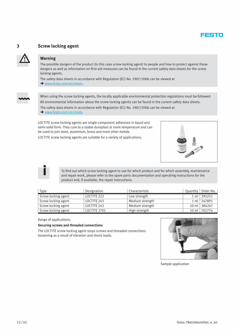
LOCTITE screw locking agents are single-component adhesives in liquid and semi-solid form. They cure to a stable duroplast at room temperature and can be used to join steel, aluminium, brass and most other metals.
LOCTITE screw locking agents are suitable for a variety of applications.
To find out which screw locking agent to use for which product and for which assembly, maintenance and repair work, please refer to the spare parts documentation and operating instructions for the product and, if available, the repair instructions.
Type Designation Characteristic Quantity Order No.
Screw locking agent LOCTITE 222 Low strength 1 ml 395251Screw locking agent LOCTITE 243 Medium strength 1 ml 247891Screw locking agent LOCTITE 243 Medium strength 10 ml 384267Screw locking agent LOCTITE 2701 High strength 10 ml 701774
Range of applications:
Securing screws and threaded connections
The LOCTITE screw locking agent stops screws and threaded connections loosening as a result of vibration and shock loads.
Sample application

13 / 45Festo 7Betriebsmittel_e_en
4 Special oils and oil guns
4.1 Special oils
When using and disposing of the special oils, the locally applicable environmental protection regulations must be followed.
All environmental information about the special oils can be found in the current safety data sheets.
The safety data sheets in accordance with Regulation (EC) No. 1907/2006 can be viewed at www.festo.com/en/msds.
To find out which special oil to use for which product and for which application, please refer to the spare parts documentation for the product and the operating instructions.
4.1.1 Special oil OFSW-32
Special oil for use in Festo lubricators.
Type Designation Quantity Order No.
Festo special oil OFSW-32 1000 ml 152811
Range of applications:
Lubricating compressed air using the
– lubricators LOE from the D series and
– lubricators MS-LOE from the MS series.
Lubricator MS9-LOE, MS series
4.1.2 Special oil OFSB-1
Special oil for hydraulic cushioning cylinders, shock absorbers and rotary indexing tables.
Type Designation Quantity Order No.
Festo special oil OFSB-1 1000 ml 207873

14 / 45 Festo 7Betriebsmittel_e_en
Range of applications:
Special oil for
– hydraulic cushioning cylinders type YZL-… and
– hydraulic cushioning cylinders type YD-…
Hydraulic cushioning cylinder
4.2 Oil guns
4.2.1 Oil guns for cushioning components
Oil gun YD
Oil gun YSR-OEP
Type Quantity Order No.
Oil gun YD 1 piece 2212Oil gun YSR-OEP 1 piece 11698
Range of applications:
– Hydraulic cushioning cylinders type YZL-… and
– hydraulic cushioning cylinders type YD-…
15 / 45Festo 7Betriebsmittel_e_en
4.2.2 Oil gun and cartridges for manual relubricating
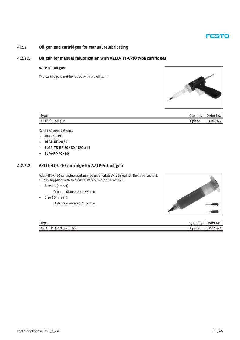
4.2.2.1 Oil gun for manual relubrication with AZLO-H1-C-10 type cartridges
AZTP-S-L oil gun
The cartridge is not included with the oil gun.
Type Quantity Order No.
AZTP-S-L oil gun 1 piece 8041022
Range of applications:
– DGE-ZR-RF
– DLGF-KF-20 / 25
– ELGA-TB-RF-70 / 80 / 120 and
– ELFA-RF-70 / 80
4.2.2.2 AZLO-H1-C-10 cartridge for AZTP-S-L oil gun
AZLO-H1-C-10 cartridge contains 10 ml Elkalub VP 916 (oil for the food sector). This is supplied with two different size metering nozzles:
– Size 15 (amber)
Outside diameter: 1.83 mm
– Size 18 (green)
Outside diameter: 1.27 mm
Type Quantity Order No.
AZLO-H1-C-10 cartridge 1 piece 8041024

16 / 45 Festo 7Betriebsmittel_e_en
4.2.2.3 AZLG-H1-C-10 cartridge for AZTP-S-L oil gun
AZLG-H1-C-10 cartridge contains 10 ml Elkalub VP 922 (grease).
Type Quantity Order No.
AZLG-H1-C-10 cartridge 1 piece 8073523
Range of applications:
– DLGF-KF-20 / 25
– ELGC
– EGSC
4.2.2.4 Metering nozzle set AZTN-DSG
Metering nozzle set AZTN-DSG contains
– 1× metering nozzle size 18, bent 45° (green)
Outside diameter: 1.27 mm
for DLGF-20
– 1× metering nozzle size 14, bent 45° (olive)
Outside diameter: 1.83 mm
for DLGF-25
Type Quantity Order No.
Metering nozzle set AZTN-DSG 1 set 8075522
Range of applications:
– DLGF-KF-20 / 25
– ELGC
– EGSC
17 / 45Festo 7Betriebsmittel_e_en
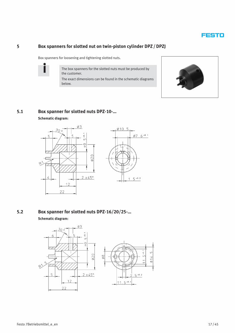
5 Box spanners for slotted nut on twin-piston cylinder DPZ / DPZJ
Box spanners for loosening and tightening slotted nuts.
The box spanners for the slotted nuts must be produced by the customer.
The exact dimensions can be found in the schematic diagrams below.
5.1 Box spanner for slotted nuts DPZ-10-…Schematic diagram:
5.2 Box spanner for slotted nuts DPZ-16/20/25-…Schematic diagram:

18 / 45 Festo 7Betriebsmittel_e_en
5.3 Box spanner for slotted nuts DPZ-32-…Schematic diagram:
Range of applications:
Twin-piston cylinder DPZ/DPZJ
The box spanner is required to fasten the yoke/end plate 2 to the piston rod 3 using the slotted nut 1.
1 Box spanner for slotted nuts
2 Slotted nut
3 Yoke/end plate
4 Twin-piston cylinder DPZ/DPZJ1 2 3 4
Sample application

19 / 45Festo 7Betriebsmittel_e_en
6 Slotted screwdriver
Slotted screwdriver for loosening and tightening slotted nuts.
Type Area of application Quantity Order No.
M3, slotted screwdriver (DIN 546) ADVUL-12/16 1 piece 384353M4, slotted screwdriver (DIN 546) ADVUL-20 – 40, ADNGF-32 – 40 1 piece 384354M5, slotted screwdriver (DIN 546) ADVUL-50 – 100, ADNGF-50 – 100 1 piece 384355
Range of applications:
Compact cylinder ADVUL-…
The slotted screwdriver is required to bolt the yoke plate/ the moment compensator 2 to the guide rod 4 using the slotted nut 1.
1 Slotted nut
2 Yoke plate/moment compensator
3 Shim
4 Guide rod1 2 3 4
Sample application
7 Mounting sleeve for solenoid valves
Mounting sleeve for fitting sealing rings.
Type Area of application Quantity Order No.
1/8" mounting sleeve Solenoid valve VL-5-1/8 and MFH-5-1/8 1 piece 2283891/4" mounting sleeve Solenoid valve VL-5-1/4 and MFH-5-1/4 1 piece 229363
Range of applications:
Solenoid valves of the type:
– VL-5-1/8
– VL-5-1/4
– MFH-5-1/8
– MFH-5-1/4
The mounting sleeve is used to fit sealing rings on the hand lever valve/stem on the above mentioned solenoid valves.
Solenoid valve MFH
20 / 45 Festo 7Betriebsmittel_e_en
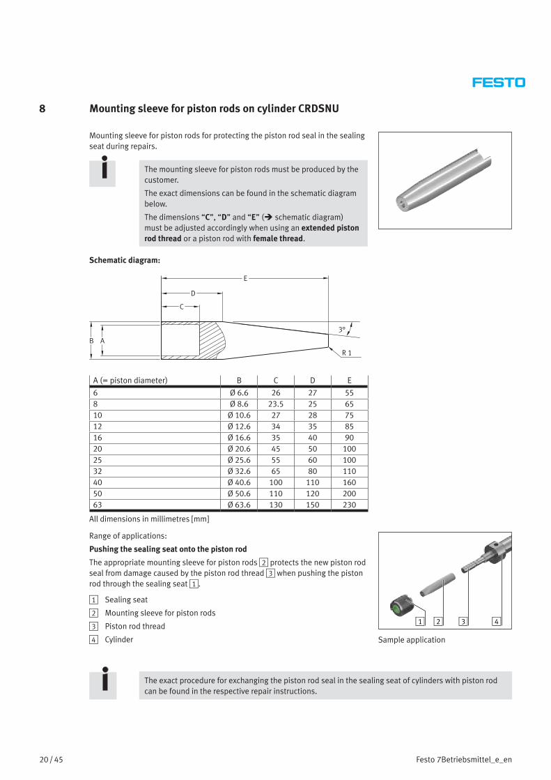
8 Mounting sleeve for piston rods on cylinder CRDSNU
Mounting sleeve for piston rods for protecting the piston rod seal in the sealing seat during repairs.
The mounting sleeve for piston rods must be produced by the customer.
The exact dimensions can be found in the schematic diagram below.
The dimensions “C”, “D” and “E” ( schematic diagram) must be adjusted accordingly when using an extended piston rod thread or a piston rod with female thread.
Schematic diagram:
B A
C
D
E
3°
R 1
A (= piston diameter) B C D E
6 Ø 6.6 26 27 558 Ø 8.6 23.5 25 6510 Ø 10.6 27 28 7512 Ø 12.6 34 35 8516 Ø 16.6 35 40 9020 Ø 20.6 45 50 10025 Ø 25.6 55 60 10032 Ø 32.6 65 80 11040 Ø 40.6 100 110 16050 Ø 50.6 110 120 20063 Ø 63.6 130 150 230
All dimensions in millimetres [mm]
Range of applications:
Pushing the sealing seat onto the piston rod
The appropriate mounting sleeve for piston rods 2 protects the new piston rod seal from damage caused by the piston rod thread 3 when pushing the piston rod through the sealing seat 1.
1 Sealing seat
2 Mounting sleeve for piston rods
3 Piston rod thread
4 Cylinder
1 42 3
Sample application
The exact procedure for exchanging the piston rod seal in the sealing seat of cylinders with piston rod can be found in the respective repair instructions.

21 / 45Festo 7Betriebsmittel_e_en
9 Mounting sleeve and pressure piece for scraper ring on the CRDSNU
The mounting sleeve and matching pressure piece prevent damage to the scraper ring when inserting it into the sealing seat of the round cylinder CRDSNU.
A sample application of these tools can be found at the end of Chapter 9.2 on page 23.
The mounting sleeve and matching pressure piece for inserting the scraper ring into the sealing seat of the round cylinder CRDSNU must be produced by the customer.
The exact dimensions can be found in the schematic diagrams below.
9.1 Mounting sleeve and pressure piece for scraper ring on the CRDSNU-12 / 16 / 20 / 25
Schematic diagram:
A B C D E
1x45°
0,5x45°F
J IH
K
G
polished
Round cylinder A B C D E F G H I J K
CRDSNU-12 Ø 18 12° Ø 11 Ø 11.5 Ø 14 R 0.4 – 8.2 9.6 6 22.6CRDSNU-16 Ø 18 12° Ø 11 Ø 11.5 Ø 14 R 0.4 – 8.2 9.6 6 22.6CRDSNU-20 Ø 24 12° Ø 14.2 Ø 16.2 Ø 17.5 R 0.4 R 1 9 12 8 24CRDSNU-25 Ø 24 12° Ø 16 Ø 16.4 Ø 17.5 – R 1 10.3 13.3 8 26
All dimensions in millimetres [mm] unless otherwise specified
22 / 45 Festo 7Betriebsmittel_e_en
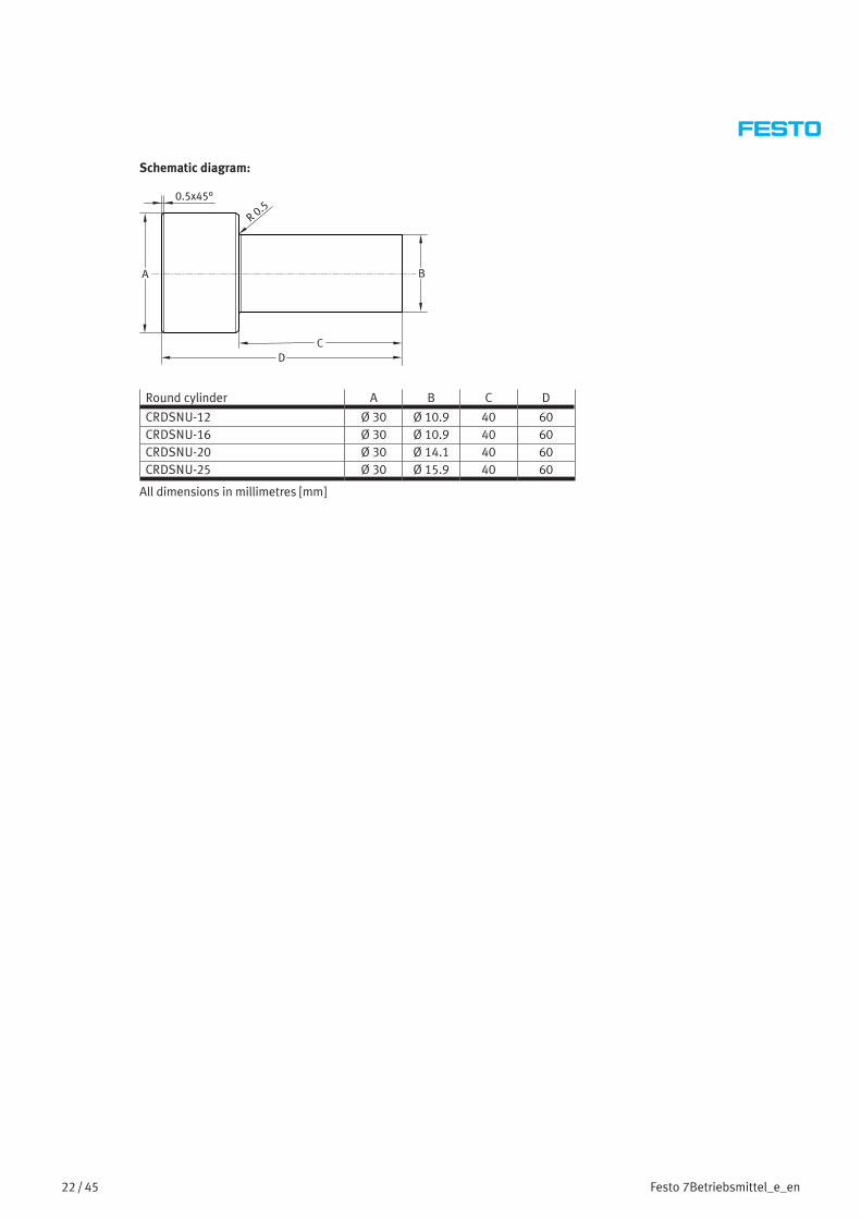
Schematic diagram:
B
DC
A
0.5x45°
R 0.5
Round cylinder A B C D
CRDSNU-12 Ø 30 Ø 10.9 40 60CRDSNU-16 Ø 30 Ø 10.9 40 60CRDSNU-20 Ø 30 Ø 14.1 40 60CRDSNU-25 Ø 30 Ø 15.9 40 60
All dimensions in millimetres [mm]
23 / 45Festo 7Betriebsmittel_e_en
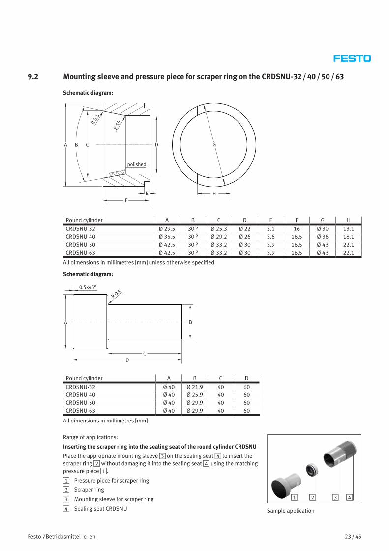
9.2 Mounting sleeve and pressure piece for scraper ring on the CRDSNU-32 / 40 / 50 / 63
Schematic diagram:
BA D
EF
R 0,
5
R 15
C G
H
polished
Round cylinder A B C D E F G H
CRDSNU-32 Ø 29.5 30 ° Ø 25.3 Ø 22 3.1 16 Ø 30 13.1CRDSNU-40 Ø 35.5 30 ° Ø 29.2 Ø 26 3.6 16.5 Ø 36 18.1CRDSNU-50 Ø 42.5 30 ° Ø 33.2 Ø 30 3.9 16.5 Ø 43 22.1CRDSNU-63 Ø 42.5 30 ° Ø 33.2 Ø 30 3.9 16.5 Ø 43 22.1
All dimensions in millimetres [mm] unless otherwise specified
Schematic diagram:
B
DC
A
0.5x45°
R 0.5
Round cylinder A B C D
CRDSNU-32 Ø 40 Ø 21.9 40 60CRDSNU-40 Ø 40 Ø 25.9 40 60CRDSNU-50 Ø 40 Ø 29.9 40 60CRDSNU-63 Ø 40 Ø 29.9 40 60
All dimensions in millimetres [mm]
Range of applications:
Inserting the scraper ring into the sealing seat of the round cylinder CRDSNU
Place the appropriate mounting sleeve 3 on the sealing seat 4 to insert the scraper ring 2 without damaging it into the sealing seat 4 using the matching pressure piece 1.
1 Pressure piece for scraper ring
2 Scraper ring
3 Mounting sleeve for scraper ring
4 Sealing seat CRDSNU
1 2 3 4
Sample application

24 / 45 Festo 7Betriebsmittel_e_en
10 Mounting sleeve for piston rod with male thread on the cylinder DNC / DSBx / DFPI / CRDNG / ADVU / AEVU
Assembly tools for piston rods with male thread for protecting the piston rod seal and the bearing in the bearing cap or sealing seat during repairs.
The assembly tools for piston rods must be produced by the customer.
The exact dimensions can be found in the schematic diagrams below.
The dimensions “C” and “D” ( schematic diagram) must be adjusted accordingly when using an extended piston rod thread.
Schematic diagram:
EC
G
F
D
Rz4Rz4
6°
A +0
,05
I +0,1
H -0
,05
B -0,1
edges rounded off
DNC / DSBx / DFPI / CRDNG
Piston diameter A B C D E F G H I
12 Ø 10 6 31 72 10 R2 Ø 4 Ø 12 10.116 Ø 12 6.5 32 84 15 R2 Ø 4 Ø 16 13.120 Ø 16 8 42 102 20 R2 Ø 4 Ø 20 17.125 Ø 20 10 52 117 25 R4 Ø 4 Ø 25 22.132 Ø 27 13 72 95 27 R4 Ø 4 Ø 32 27.140 Ø 36 17 94 122 31 R4 Ø 4 Ø 40 36.150 Ø 42 17 106 140 37 R4 Ø 4 Ø 50 46.163 Ø 48 17 118 164 49 R4 Ø 4 Ø 63 55.1
All dimensions in millimetres [mm]
ADVU / AEVU
Piston diameter A B C D E F G H I
12 Ø 10 4.75 30 53 20 R1 Ø 4 Ø 12 10.116 Ø 12 6.14 32 55 20 R1 Ø 4 Ø 16 13.116 Ø 12 6.14 32 55 20 R1 Ø 4 Ø 16 13.120 Ø 16 7.14 42 66 25 R2 Ø 4 Ø 20 17.125 Ø 20 9 55 90 34 R2 Ø 8 Ø 25 22.132 Ø 27 13.2 60 95 34 R2 Ø 8 Ø 32 27.1
All dimensions in millimetres [mm]
25 / 45Festo 7Betriebsmittel_e_en
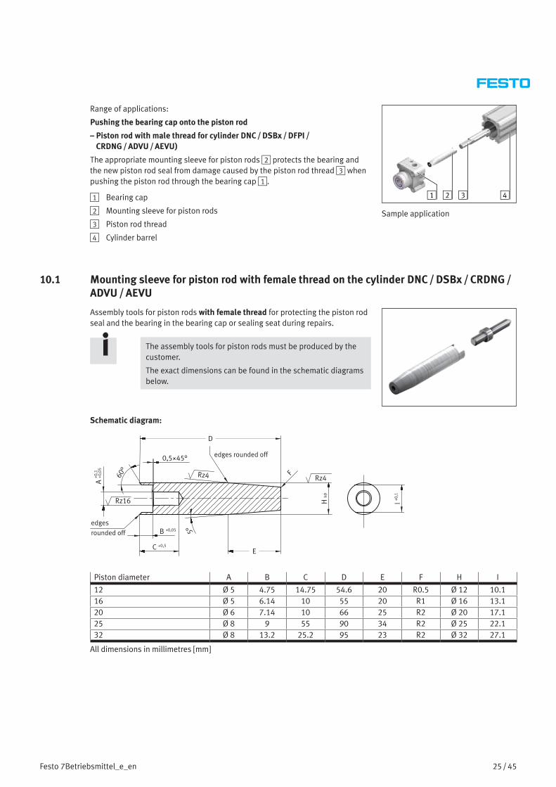
Range of applications:
Pushing the bearing cap onto the piston rod
– Piston rod with male thread for cylinder DNC / DSBx / DFPI / CRDNG / ADVU / AEVU)
The appropriate mounting sleeve for piston rods 2 protects the bearing and the new piston rod seal from damage caused by the piston rod thread 3 when pushing the piston rod through the bearing cap 1.
1 Bearing cap
2 Mounting sleeve for piston rods
3 Piston rod thread
4 Cylinder barrel
1 42 3
Sample application
10.1 Mounting sleeve for piston rod with female thread on the cylinder DNC / DSBx / CRDNG /ADVU / AEVU
Assembly tools for piston rods with female thread for protecting the piston rod seal and the bearing in the bearing cap or sealing seat during repairs.
The assembly tools for piston rods must be produced by the customer.
The exact dimensions can be found in the schematic diagrams below.
Schematic diagram:
edges rounded off
E
D
F
B +0,05
C +0,5
Rz4
Rz16
60°
5°
H h9
Rz4
A +0
,1+0
,05
0,5×45°
I +0,1
edges rounded off
Piston diameter A B C D E F H I
12 Ø 5 4.75 14.75 54.6 20 R0.5 Ø 12 10.116 Ø 5 6.14 10 55 20 R1 Ø 16 13.120 Ø 6 7.14 10 66 25 R2 Ø 20 17.125 Ø 8 9 55 90 34 R2 Ø 25 22.132 Ø 8 13.2 25.2 95 23 R2 Ø 32 27.1
All dimensions in millimetres [mm]

26 / 45 Festo 7Betriebsmittel_e_en
10.2 Mandrel for piston rod with female thread on the cylinder DNC / DSBx / CRDNG /ADVU / AEVU
Schematic diagram:
Rz16
30°
A -0
,05
B -0
,1
E -0,2D
C
GGF
H -0
,05
-0,1
Piston diameter A B C D E F G H
12 Ø 6.35 Ø 4.5 3 9.7 2.3 20 0.5 ×45° Ø 516 Ø 8.35 Ø 6.2 4 12.9 3.1 24 0.5 ×45° Ø 520 Ø 10.45 Ø 8 5 17 4.4 29.5 0.5 ×45° Ø 625 Ø 12.95 Ø 9.8 5 19 5.9 36 1 ×45° Ø 832 Ø 16.95 Ø 13.9 10 23.1 6.9 40 1 ×45° Ø 8
All dimensions in millimetres [mm]
Range of applications:
Pushing the bearing cap onto the piston rod with female thread for cylinder DNC / DSBx / CRDNG /ADVU / AEVU
The appropriate mounting sleeve for piston rods 2 and a mandrel 3 protects the bearing and the new piston rod seal from damage caused by the piston rod 4 when pushing the piston rod with female thread 4 through the bearing cap 1.
1 Bearing cap
2 Mounting sleeve for piston rods
3 Mandrel
4 Piston rod with female thread
5 Cylinder barrel
1 52 43
Sample application
A mandrel 2 is additionally inserted into the female thread of the piston rod for piston rods with female thread 3. The mounting sleeve for piston rods 1 is placed on this mandrel 2.
1 Mounting sleeve for piston rods
2 Mandrel
3 Piston rod with female thread
31 2

27 / 45Festo 7Betriebsmittel_e_en
11 Mounting sleeve and pressure piece for scraper ring on the DNC / DSBx / DFPI / DFPI-NB3P / CRDNG
The mounting sleeve and matching pressure piece prevent damage to the scraper ring when inserting it into the bearing cap.
Sample applications of these tools can be found at the end of Chapter 11.1 on page 27 and at the end of Chapter 11.2 on page 29.
The mounting sleeve and matching pressure piece for inserting the scraper ring into the bearing cap must be produced by the customer.
The exact dimensions can be found in the schematic diagrams below.
11.1 Mounting sleeve and pressure piece for scraper ring on the DNC / DSBx / DFPI-NB3P / CRDNG
Schematic diagram:
Piston diameter A B C D E
32 Ø 52 Ø 30 Ø 21 40 2440 Ø 52 Ø 35 Ø 25 42 2450 Ø 53 Ø 40 Ø 29 50 2463 Ø 53 Ø 45 Ø 29 50 2480 Ø 53 Ø 45 Ø 34 57 24100 Ø 61 Ø 55.5 Ø 34 61 24125 Ø 66 Ø 61.5 Ø 41 68 24160 Ø 71 Ø 65.5 Ø 49.1 84 24200 Ø 81 Ø 75.5 Ø 49.1 89 24250 Ø 96 Ø 90.5 Ø 59.2 103 24320 Ø 116 Ø 110.5 Ø 74.2 113 24
All dimensions in millimetres [mm]

28 / 45 Festo 7Betriebsmittel_e_en
Schematic diagram:
3
Piston diameter A B C D E F
32 Ø 37 Ø 12 Ø 20.8 16 40.5 5640 Ø 41 Ø 16 Ø 24.8 16 40.5 5650 Ø 45 Ø 20 Ø 28.8 16 40.5 5663 Ø 45 Ø 20 Ø 28.8 16 40.5 5680 Ø 50 Ø 25 Ø 33.8 17.5 42 70100 Ø 50 Ø 25 Ø 33.8 17.5 42 70125 Ø 58 Ø 32 Ø 40.8 17.5 42 70160 Ø 65 Ø 40 Ø 48.9 17.5 42 70200 Ø 65 Ø 40 Ø 48.9 17.5 42 70250 Ø 75 Ø 50 Ø 59 19 45 80320 Ø 90 Ø 63 Ø 74 20 45 80
All dimensions in millimetres [mm]
Range of applications:
1 Pressure piece for scraper ring
2 Scraper ring
3 Mounting sleeve for scraper ring
4 DNC bearing cap
1 2 3 4
Sample application
29 / 45Festo 7Betriebsmittel_e_en
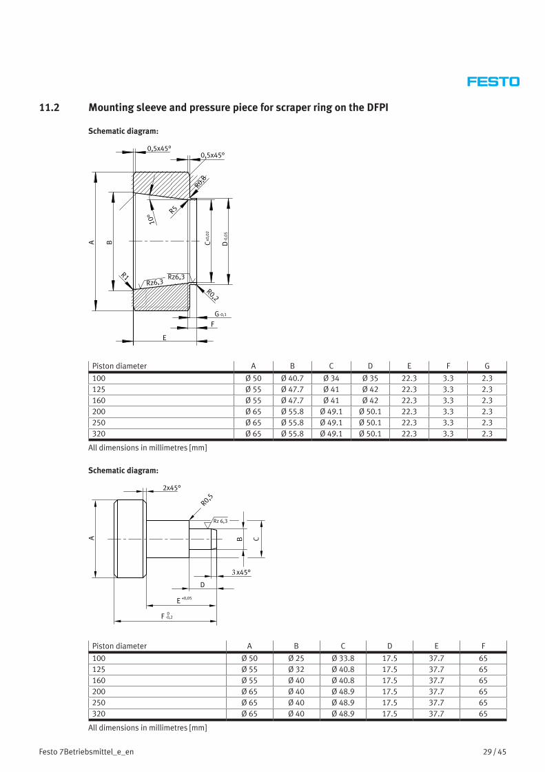
11.2 Mounting sleeve and pressure piece for scraper ring on the DFPI
Schematic diagram:
Piston diameter A B C D E F G
100 Ø 50 Ø 40.7 Ø 34 Ø 35 22.3 3.3 2.3125 Ø 55 Ø 47.7 Ø 41 Ø 42 22.3 3.3 2.3160 Ø 55 Ø 47.7 Ø 41 Ø 42 22.3 3.3 2.3200 Ø 65 Ø 55.8 Ø 49.1 Ø 50.1 22.3 3.3 2.3250 Ø 65 Ø 55.8 Ø 49.1 Ø 50.1 22.3 3.3 2.3320 Ø 65 Ø 55.8 Ø 49.1 Ø 50.1 22.3 3.3 2.3
All dimensions in millimetres [mm]
Schematic diagram:
3
Piston diameter A B C D E F
100 Ø 50 Ø 25 Ø 33.8 17.5 37.7 65125 Ø 55 Ø 32 Ø 40.8 17.5 37.7 65160 Ø 55 Ø 40 Ø 40.8 17.5 37.7 65200 Ø 65 Ø 40 Ø 48.9 17.5 37.7 65250 Ø 65 Ø 40 Ø 48.9 17.5 37.7 65320 Ø 65 Ø 40 Ø 48.9 17.5 37.7 65
All dimensions in millimetres [mm]

30 / 45 Festo 7Betriebsmittel_e_en
Range of applications:
1 Pressure piece for scraper ring
2 Scraper ring
3 Mounting sleeve for scraper ring
4 DFPI bearing cap
1 2 3 4
Sample application

31 / 45Festo 7Betriebsmittel_e_en
12 Centring tool and tubular box spanner for mounting the cushioning bosses on cylinders of the type ADN-…-PPS and ADNGF-…-PPS
12.1 Centring tool for the cushioning bosses on cylinders of the type ADN-…-PPS and ADNGF-…-PPS
The centring tool for the cushioning bosses is used to centre the front cushioning boss on the piston rod on cylinders of the type ADN-…-PPS and ADNGF-…-PPS.
Type Area of application Piston diameter [mm] Quantity Order No.
Centring tool Cushioning boss ADN/ADNGF-32-…-PPS 12 1 piece 1356097Centring tool Cushioning boss ADN/ADNGF-40-…-PPS 12 1 piece 1437387Centring tool Cushioning boss ADN/ADNGF-50-…-PPS 16 1 piece 1437415Centring tool Cushioning boss ADN/ADNGF-63-…-PPS 16 1 piece 1437415Centring tool Cushioning boss ADN/ADNGF-80-…-PPS 20 1 piece 1441528Centring tool Cushioning boss ADN/ADNGF-100-…-PPS 20 1 piece 2585245
Type Area of application Piston diameter [mm] Quantity Order No.
Cushioning boss Cushioning boss ADN/ADNGF-32-…-PPS 12 2 piece 1273587Cushioning boss Cushioning boss ADN/ADNGF-40-…-PPS 12 2 piece 1280390Cushioning boss Cushioning boss ADN/ADNGF-50-…-PPS 16 2 piece 1271128Cushioning boss Cushioning boss ADN/ADNGF-63-…-PPS 16 2 piece 1280411Cushioning boss Cushioning boss ADN/ADNGF-80-…-PPS 20 2 piece 1273684Cushioning boss Cushioning boss ADN/ADNGF-100-…-PPS 20 2 piece 1724489
Further information on spare parts for cylinders of the type ADN / ADNGF-…-PPS can be found in the online spare parts catalogue on the Festo website ( www.festo.com/spareparts).
Range of applications:
Compact cylinders of the type:
– ADN-…-PPS
– ADNGF-…-PPS
Place the centring tool 2 on the piston rod 1 to centre the front cushioning boss 3 on the piston rod 1 and secure it until the piston module 4 and the rear cushioning boss 5 are permanently mounted on the piston rod 1 using a hex nut ( Chapter 12.2 on page 32) or a second piston rod (with S2 / S20). Then remove the centring tool 2 from the piston rod 1.
1 Piston rod
2 Centring tool
3 Front cushioning boss
4 Piston module
5 Rear cushioning boss
6 Washer
7 Hex nut
321 4 5 6 7
Sample application
1 3 4
ADN-32-…-PPS

32 / 45 Festo 7Betriebsmittel_e_en
12.2 Tubular box spanner for dismounting and mounting the cushioning bosses on cylinders of the type ADN-…-PPS and ADNGF-…-PPS
Tubular box spanner for loosening and tightening the hex nuts on the piston rod on cylinders of the type ADN/ADNGF-…-PPS. This tubular box spanner protects the cushioning boss against damage.
Type Area of application Wall thickness
Tubular box spanner, A/F 13 ADN/ADNGF-32-…-PPS 1.6 mmTubular box spanner, A/F 17 ADN/ADNGF-40-…-PPS 1.6 mmTubular box spanner, A/F 19 ADN/ADNGF-50-…-PPS 2.3 mmTubular box spanner, A/F 19 ADN/ADNGF-63-…-PPS 2.3 mmTubular box spanner, A/F 22 ADN/ADNGF-80-…-PPS 2.3 mmTubular box spanner, A/F 22 ADN/ADNGF-100-…-PPS 2.3 mm
The wall thickness of the tubular box spanner used together with the size of the spanner are key for ensuring that the installation is completed without damaging the cushioning boss.
Range of applications:
Exchanging the cushioning bosses on compact cylinders of the type:
– ADN-…-PPS
– ADNGF-…-PPS
Use the tubular box spanner 8 to loosen or tighten the hex nut 7 on the piston rod 1 without damaging the rear cushioning boss 5.
1 Piston rod
2 Centring tool
3 Front cushioning boss (covered)
4 Piston module
5 Rear cushioning boss
6 Washer
7 Hex nut
8 Box spanner
321 4 5 6 87
Sample application
The exact procedure for exchanging the cushioning bosses can be found in the respective repair instructions. This can be found on the Festo website ( www.festo.com/spareparts).
33 / 45Festo 7Betriebsmittel_e_en
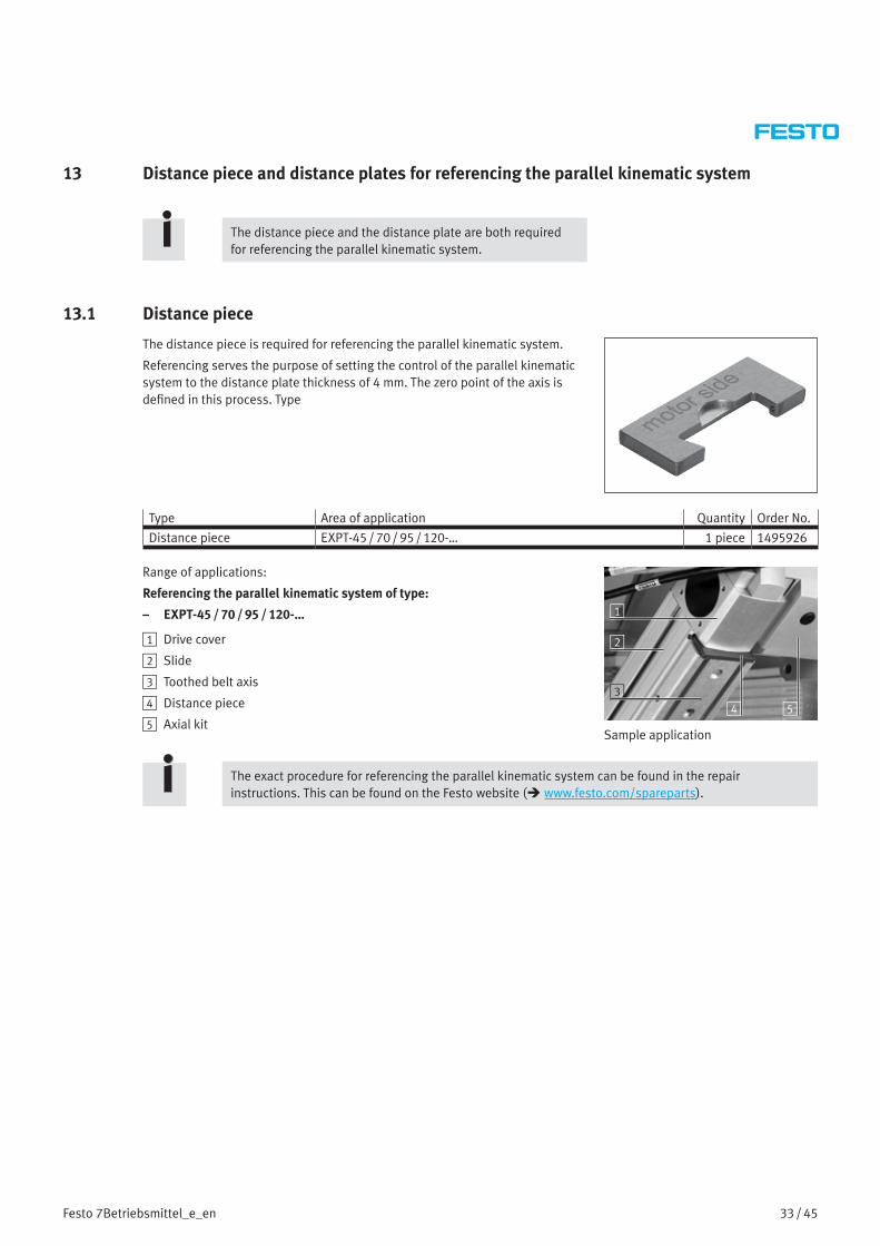
13 Distance piece and distance plates for referencing the parallel kinematic system
The distance piece and the distance plate are both required for referencing the parallel kinematic system.
13.1 Distance piece
The distance piece is required for referencing the parallel kinematic system.
Referencing serves the purpose of setting the control of the parallel kinematic system to the distance plate thickness of 4 mm. The zero point of the axis is defined in this process. Type
Type Area of application Quantity Order No.
Distance piece EXPT-45 / 70 / 95 / 120-… 1 piece 1495926
Range of applications:
Referencing the parallel kinematic system of type:
– EXPT-45 / 70 / 95 / 120-…
1 Drive cover
2 Slide
3 Toothed belt axis
4 Distance piece
5 Axial kit4 5
3
1
2
Sample application
The exact procedure for referencing the parallel kinematic system can be found in the repair instructions. This can be found on the Festo website ( www.festo.com/spareparts).

34 / 45 Festo 7Betriebsmittel_e_en
13.2 Distance plate for parallel kinematic system EXPT-45 / 70
The distance plate is required for referencing the parallel kinematic system.
The parameters of the motor controllers are set correctly to the zero point using the distance plate (nominal dimension of the distance plate 350 mm).
The distance plate must be produced by the customer.
The exact dimensions can be found in the schematic diagram below.
Schematic diagram:
t=8 I
D
HG
FE0
C
A
B
C
R4R4R4
J
J// 0.05
A B C D E F G H I
14+0.2 18+0.1 5+0.2 350 5.1-0.1 15+0.1 35-0.1 45+0.1 50
All dimensions in millimetres [mm]
Range of applications:
Referencing the parallel kinematic system of type:
– EXPT-45 / 70-…
1 Drive cover
2 Slide
3 Toothed belt axis
4 Distance plate
5 Axial kit
6 Servomotor
43 5 62
1
Sample application
The exact procedure for referencing the parallel kinematic system can be found in the repair instructions. This can be found on the Festo website ( www.festo.com/spareparts).

35 / 45Festo 7Betriebsmittel_e_en
13.3 Distance plate for parallel kinematic system EXPT-95 / 120
The distance plate is required for referencing the parallel kinematic system.
The parameters of the motor controllers are set correctly to the zero point using the distance plate (nominal dimension of the distance plate 600 mm).
The distance plate must be produced by the customer.
The exact dimensions can be found in the schematic diagram below.
Schematic diagram:
t=8
D
A
(E)C
B
R3
0.5x45°
F
F// 0.05
A B C D (E)
600 6-0.1 34+0.1 5-0.1 45
All dimensions in millimetres [mm]
Range of applications:
Referencing the parallel kinematic system of type:
– EXPT-95 / 120-…
The exact procedure for referencing the parallel kinematic system can be found in the repair instructions. This can be found on the Festo website ( www.festo.com/spareparts).
36 / 45 Festo 7Betriebsmittel_e_en
14 Devices for checking the toothed belt pretension
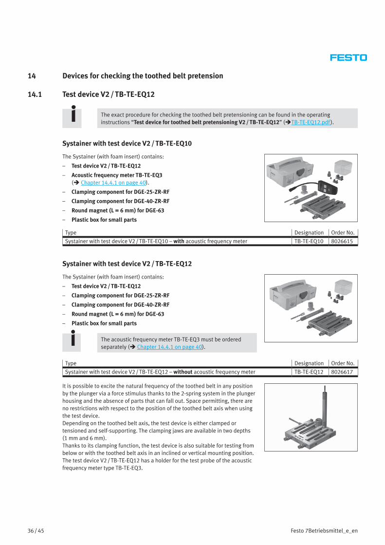
14.1 Test device V2 / TB-TE-EQ12
The exact procedure for checking the toothed belt pretensioning can be found in the operating instructions “Test device for toothed belt pretensioning V2 / TB-TE-EQ12” (TB-TE-EQ12.pdf ).
Systainer with test device V2 / TB-TE-EQ10
The Systainer (with foam insert) contains:
– Test device V2 / TB-TE-EQ12
– Acoustic frequency meter TB-TE-EQ3 ( Chapter 14.4.1 on page 40).
– Clamping component for DGE-25-ZR-RF
– Clamping component for DGE-40-ZR-RF
– Round magnet (L = 6 mm) for DGE-63
– Plastic box for small parts
Type Designation Order No.
Systainer with test device V2 / TB-TE-EQ10 – with acoustic frequency meter TB-TE-EQ10 8026615
Systainer with test device V2 / TB-TE-EQ12
The Systainer (with foam insert) contains:
– Test device V2 / TB-TE-EQ12
– Clamping component for DGE-25-ZR-RF
– Clamping component for DGE-40-ZR-RF
– Round magnet (L = 6 mm) for DGE-63
– Plastic box for small parts
The acoustic frequency meter TB-TE-EQ3 must be ordered separately ( Chapter 14.4.1 on page 40).
Type Designation Order No.
Systainer with test device V2 / TB-TE-EQ12 – without acoustic frequency meter TB-TE-EQ12 8026617
It is possible to excite the natural frequency of the toothed belt in any position by the plunger via a force stimulus thanks to the 2-spring system in the plunger housing and the absence of parts that can fall out. Space permitting, there are no restrictions with respect to the position of the toothed belt axis when using the test device.Depending on the toothed belt axis, the test device is either clamped or tensioned and self-supporting. The clamping jaws are available in two depths (1 mm and 6 mm).Thanks to its clamping function, the test device is also suitable for testing from below or with the toothed belt axis in an inclined or vertical mounting position.The test device V2 / TB-TE-EQ12 has a holder for the test probe of the acoustic frequency meter type TB-TE-EQ3.

37 / 45Festo 7Betriebsmittel_e_en
Range of applications:
Checking the toothed belt pretensioning on toothed belt axes type:
– DGE-25 / 40 / 63-ZR-RF
– DGE-25 / 40 / 63-ZR-(KF)
– DGEA-18 / 25 / 40-ZR
– EGC-50 / 70 / 80 / 120 / 185-TB-KF
– EGC-HD-125-TB
– EGC-HD-160 / 220-TB-(GP)
– ELGA-70 / 80 / 120-TB-G
– ELGA-70 / 80 / 120-TB-RF/-KF-…(F1)
– ELGA-150-TB-KF
The toothed belt pretensioning of the above mentioned toothed belt axes can be checked using the acoustic frequency meter TB-TE-EQ3 connected to the test device V2 / TB-TE-EQ12.
Sample application
14.2 Mounting kit TB-TE-EQ4 for test device V1 / TB-TE-EQ2 for toothed belt axis ELGA-TB-G / RF-(F1) / KF-(F1)
The mounting kit TB-TE-EQ4 can only be used in combination with the test device V1 / TB-TE-EQ2 ( Chapter 14.2 on page 37) for checking the toothed belt pretensioning on toothed belt axes of the type ELGA-TB-G / RF-(F1) / KF-(F1) for size 70 / 80 / 120 .
The mounting kit TB-TE-EQ4 cannot be used for ELGA-TB-KF-150. For ELGA-TB-KF-150 measure without device. The procedure is described in the repair instructions.
The acoustic frequency meter TB-TE-EQ3 must be ordered separately ( Chapter 14.4.1 on page 40).
The test device V1 / TB-TE-EQ2 is no longer available.
Contents of the mounting kit TB-TE-EQ4:
1 Position stop bolt
2 Left-hand position stop
3 Right-hand position stop
4 Distance piece for ELGA-TB-G-120 / RF-120-(F1) / KF-120-(F1)
5 Distance piece for ELGA-TB-G-80 / RF-80-(F1) / KF-80-(F1)
6 Distance piece for ELGA-TB-G-70 / RF-70-(F1) / KF-70-(F1)
7 Transport holder for distance pieces7
1 32
6 5 4
Type Designation Order No.
Mounting kit TB-TE-EQ4 for toothed belt axis ELGA-TB-G / RF-(F1) / KF-(F1) TB-TE-EQ4 760460
38 / 45 Festo 7Betriebsmittel_e_en
Range of applications:
Checking the toothed belt pretensioning only on toothed belt axes ELGA-TB-G / RF / KF-70 / 80 / 120
The toothed belt pretensioning of the above-mentioned toothed belt axes can be checked using the acoustic frequency meter TB-TE-EQ3 connected to the test device V1/ TB-TE-EQ2 and with the mounting kit TB-TE-EQ4.
The mounting kit TB-TE-EQ4 cannot be used for ELGA-TB-KF-150. For ELGA-TB-KF-150 measure without device. The procedure is described in the repair instructions. Sample application
The exact procedure for checking the toothed belt pretensioning using the mounting kit can be found in the operating instructions “Test device for toothed belt pretensioning V1 / TB-TE-EQ2” ( TB-TE-EQ02.pdf ).
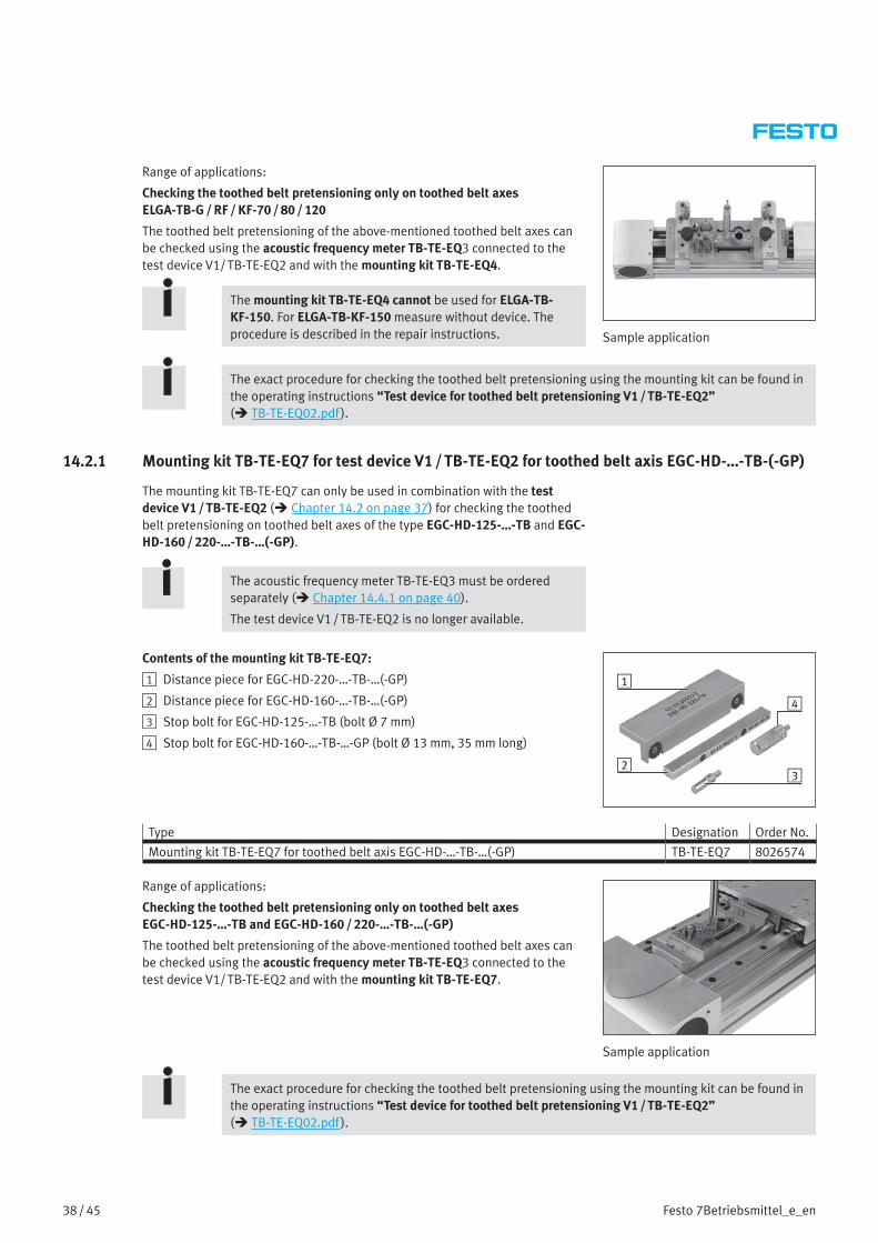
14.2.1 Mounting kit TB-TE-EQ7 for test device V1 / TB-TE-EQ2 for toothed belt axis EGC-HD-…-TB-(-GP)
The mounting kit TB-TE-EQ7 can only be used in combination with the test device V1 / TB-TE-EQ2 ( Chapter 14.2 on page 37) for checking the toothed belt pretensioning on toothed belt axes of the type EGC-HD-125-…-TB and EGC-HD-160 / 220-…-TB-…(-GP).
The acoustic frequency meter TB-TE-EQ3 must be ordered separately ( Chapter 14.4.1 on page 40).
The test device V1 / TB-TE-EQ2 is no longer available.
Contents of the mounting kit TB-TE-EQ7:
1 Distance piece for EGC-HD-220-…-TB-…(-GP)
2 Distance piece for EGC-HD-160-…-TB-…(-GP)
3 Stop bolt for EGC-HD-125-…-TB (bolt Ø 7 mm)
4 Stop bolt for EGC-HD-160-…-TB-…-GP (bolt Ø 13 mm, 35 mm long)
1
2
4
3
Type Designation Order No.
Mounting kit TB-TE-EQ7 for toothed belt axis EGC-HD-…-TB-…(-GP) TB-TE-EQ7 8026574
Range of applications:
Checking the toothed belt pretensioning only on toothed belt axes EGC-HD-125-…-TB and EGC-HD-160 / 220-…-TB-…(-GP)
The toothed belt pretensioning of the above-mentioned toothed belt axes can be checked using the acoustic frequency meter TB-TE-EQ3 connected to the test device V1/ TB-TE-EQ2 and with the mounting kit TB-TE-EQ7.
Sample application
The exact procedure for checking the toothed belt pretensioning using the mounting kit can be found in the operating instructions “Test device for toothed belt pretensioning V1 / TB-TE-EQ2” ( TB-TE-EQ02.pdf ).

39 / 45Festo 7Betriebsmittel_e_en
14.3 Test device TB-TE-EQ5
The test device TB-TE-EQ5 has a holder for the test probe of the acoustic frequency meter type TB-TE-EQ3 and makes it possible to excite the toothed belt by means of a plunger.
The acoustic frequency meter TB-TE-EQ3 must be ordered separately ( Chapter 14.4.1 on page 40).
Type Designation Order No.
Test device TB-TE-EQ5 TB-TE-EQ5 760461
Range of applications:
Checking the toothed belt pretensioning on drives of type:
– ERMB
– EHMB
The toothed belt pretensioning of the above mentioned drives can be checked using the acoustic frequency meter TB-TE-EQ3 connected to the test device TB-TE-EQ5.
Sample application
The exact procedure for checking the toothed belt pretensioning on drives ERMB and EHMB can be found in the respective repair instructions. This can be found on the Festo website ( www.festo.com/spareparts).
40 / 45 Festo 7Betriebsmittel_e_en
14.4 Accessories for devices
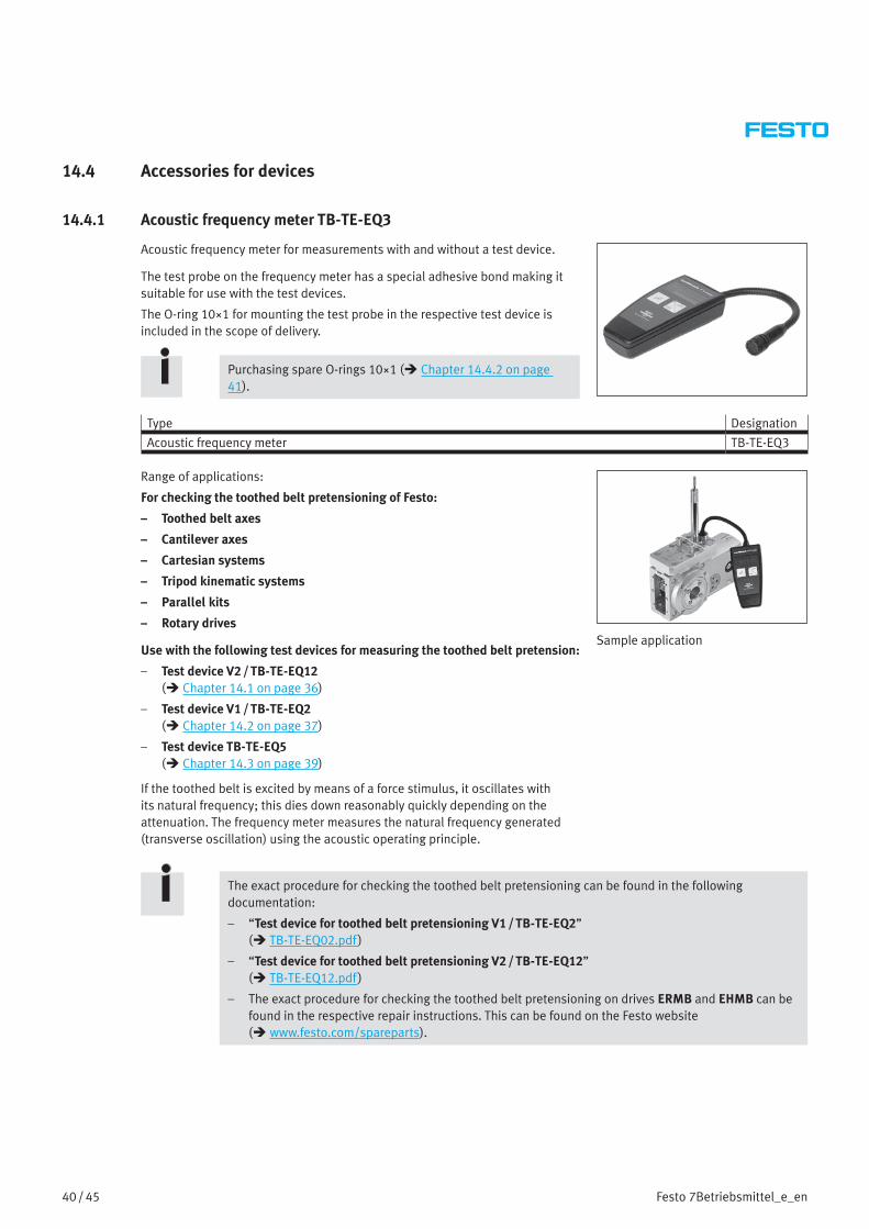
14.4.1 Acoustic frequency meter TB-TE-EQ3
Acoustic frequency meter for measurements with and without a test device.
The test probe on the frequency meter has a special adhesive bond making it suitable for use with the test devices.
The O-ring 10×1 for mounting the test probe in the respective test device is included in the scope of delivery.
Purchasing spare O-rings 10×1 ( Chapter 14.4.2 on page 41).
Type Designation
Acoustic frequency meter TB-TE-EQ3
Range of applications:
For checking the toothed belt pretensioning of Festo:
– Toothed belt axes
– Cantilever axes
– Cartesian systems
– Tripod kinematic systems
– Parallel kits
– Rotary drives
Use with the following test devices for measuring the toothed belt pretension:
– Test device V2 / TB-TE-EQ12 ( Chapter 14.1 on page 36)
– Test device V1 / TB-TE-EQ2 ( Chapter 14.2 on page 37)
– Test device TB-TE-EQ5 ( Chapter 14.3 on page 39)
If the toothed belt is excited by means of a force stimulus, it oscillates with its natural frequency; this dies down reasonably quickly depending on the attenuation. The frequency meter measures the natural frequency generated (transverse oscillation) using the acoustic operating principle.
Sample application
The exact procedure for checking the toothed belt pretensioning can be found in the following documentation:
– “Test device for toothed belt pretensioning V1 / TB-TE-EQ2” ( TB-TE-EQ02.pdf )
– “Test device for toothed belt pretensioning V2 / TB-TE-EQ12” ( TB-TE-EQ12.pdf )
– The exact procedure for checking the toothed belt pretensioning on drives ERMB and EHMB can be found in the respective repair instructions. This can be found on the Festo website ( www.festo.com/spareparts).

41 / 45Festo 7Betriebsmittel_e_en
14.4.2 Spare O-ring 10×1
For mounting the test probe of the frequency meter TB-TE-EQ3 in the respective test device by means of clamping friction.
The O-ring 10×1 is included in the scope of delivery of the frequency meter TB-TE-EQ3 ( Chapter 14.4.1 on page 40).
Type Quantity Order No.
O-ring 10×1 1 piece 200926

42 / 45 Festo 7Betriebsmittel_e_en
15 Clamping elements
The clamping elements EADT-S-L5-… are used to clamp the cover band of the ELGA axes. The clamping element assigned to the axis is placed on the cover band, as shown in the sample application. By pressing the clamping element onto the cover band and pushing it towards the actuator end cap at the same time, the cover band is pushed into the slot provided in the actuator end cap and is clamped using the two threaded pins.
Type Area of application Quantity Order No.
Clamping element EADT-S-L5-32 ELGC-TB / BS-32 / 45 1 piece 8065818ELFC-KF-32 / 45
Clamping element EADT-S-L5-70 ELGA-G / RF / KF-70 / 80 1 piece 8058451ELFA-KF / RF-70 / 80ELGC-TB / BS-60 / 80ELFC-KF-60 / 80
Clamping element EADT-S-L5-120 ELGA-G / RF / KF-120 / 150 1 piece 8058450ELFA-KF-120
Range of applications:
Clamping the cover band
1 Drive cover with corner pulley
2 Cover band
3 Clamping element EADT-S-L5-…
3 Toothed belt axis ELGA-TB-KF
3 42
1
Sample application
43 / 45Festo 7Betriebsmittel_e_en
16 Cleaning and greasing
16.1 Cleaning
The components must be thoroughly cleaned of all foreign particles, machining residues and old lubricants before they are greased.
NoteClean with a soft, lint-free cloth and non-abrasive cleaning agents.
Check the compatibility of the cleaning agent with the materials to be cleaned.
16.2 GreasingThe different components require different levels of greasing depending on a number of factors.
To find out which lubricating grease to use for which product and for instructions on greasing the individual components, please refer to the spare parts documentation and operating instructions and, if available, the repair instructions for the product. There you will also find precise indications for e.g. relubrication intervals, application, etc.
16.2.1 Extremely thin grease film
A barely continuous film of grease covers the bearing surface. The grease can give a sheen to the surface; however, the colour of the grease must not darken it.
Recommendation:Apply the grease using a cloth or similar dipped in the grease.Remove the excess grease from the seal system components (e.g. by drawing the assembled piston with the piston rod once fully through the greased cylinder barrel) and then remove the excess from the seal components by wiping it off.
16.2.2 Thin grease film
A film of grease covers the bearing surface so that a continuous film of grease exists and the grease colour darkens the surface slightly.
Recommendation:Apply the grease with a soft brush or similar.
16.2.3 Grease reservoir
There is a certain amount of oil enclosed between two sealing rims or in enclosed ring volumes.
16.2.4 Assembly greasing
Thin film of grease on the surface of sealing elements and on installation spaces, mating surfaces and edges, over which the sealing elements must be moved for assembly.

44 / 45 Festo 7Betriebsmittel_e_en
17 Liability
The General Terms and Conditions of Business (AGB) of Festo AG & Co. KG, which can be viewed on the Festo website ( www.festo.com), apply.

45 / 45Festo 7Betriebsmittel_e_en
Conditions of use for “Electronic documentation”
I. Protection rights and scope of use
The file of your choice is subject to protective provisions. Festo or third parties have protective rights to this electronic documentation, which Festo provides both on portable data storage devices (diskettes, CD ROM, removable disks) as well as on the Internet and/or intranet, referred to as electronic documentation below. In so far as third parties have whole or partial right of access to this electronic documentation, Festo has the appropriate rights of use. Festo permits the user the use under the following conditions:
1. Scope of use
a) The user of the electronic documentation is allowed to use this documentation for his own, exclusively company-internal purposes on any number of machines within his business premises (location). This right of use includes exclusively the right to save the electronic documentation on the central processors (machines) used at the location.
b) The electronic documentation may be printed out on a printer at the location of the user as often as desired, providing this printout is printed with or kept in a safe place together with these conditions of use and other user instructions.
c) With the exception of the Festo logo, the user has the right to use pictures and texts from the electronic documentation for creating his own machine and system documentation. The use of the Festo logo requires written consent from Festo. The user is responsible for ensuring that the pictures and texts used match the machine/system or the product.
d) Further uses are permitted within the following framework:
Copying exclusively for use within the framework of machine and system documentation from electronic documents of all documented supplier components. Demonstrating to third parties exclusively under guarantee that no data material is stored wholly or partly in other networks or other data storage devices or can be reproduced there.
Passing on printouts to third parties not covered by the regulation in item 3, as
well as any processing or other use are not permitted.
2. Copyright note
Every “electronic document” receives a copyright note. This note must be included on every copy and every printout.
Example: E 2003, Festo AG & Co. KG, D-73726 Esslingen
3. Transferring the authorisation of use
The user can transfer the authorization of use in the scope of and with the limitations of the conditions in accordance with items 1 and 2 completely to a third party. The third party must be made explicitly aware of these conditions of use.
II. Exporting the electronic documentation
When exporting the electronic documentation, the licence holder must observe the export regulations of the exporting country and those of the purchasing country.
III. Warranty
1. Festo products are being continuously developed with regard to hardware and software. The hardware status and, where applicable, the software status of the product can be found on the name plate of the product. If the electronic documentation, in whatever form, is not supplied with the product, i.e. is not supplied on a data storage device (diskettes, CD ROM, removable disk) as a delivery unit with the relevant product, Festo does not guarantee that the electronic documentation corresponds to every hardware and software status of the product. In this case, the printed documentation from Festo accompanying the product alone is decisive for ensuring that the hardware and software status of the product matches that of the electronic documentation.
2. The information contained in this electronic documentation can be amended by Festo without prior notice and does not commit Festo in any way.
IV. Liability/limitations on liability
1. Festo provides this electronic documentation in order to assist the user in creating his machine and system documentation. In the case that electronic documentation in the form of data storage devices (diskettes, CD ROM, removable disk) does not accompany a product, i.e. is not automatically supplied together with that product, Festo does not guarantee that the electronic documentation separately available/supplied matches the product actually used by the user.
The latter applies particularly to extracts of the documents for the user’s own documentation. The guarantee and liability for separately available/supplied portable data storage devices, i.e. with the exception of electronic documentation provided on the Internet/intranet, are limited exclusively to proper duplication of the software, whereby Festo guarantees that in each case the relevant portable data storage device or software contains the latest status of the documentation. In respect of the electronic documentation available on the Internet/Intranet, there is no guarantee that it will have the same version status as the last printed edition.
2. Furthermore, Festo cannot be held liable for the lack of economic success or for damage or claims by third parties resulting from the use of the documentation by the user, with the exception of claims arising from infringement of the protection rights of third parties concerning the use of the electronic documentation.
3. The limitations on liability as per paragraphs 1 and 2 do not apply if, in cases of intent or gross negligence or lack of warranted quality, a compulsory liability exists. In such a case, Festo’s liability is limited to the damage discernable by Festo when the concrete circumstances are made known.
V. Safety guidelines/documentation
Warranty and liability claims in conformity with the aforementioned regulations (points III. and IV) may be raised only if the user has observed the safety guidelines of the documentation in conjunction with the use of the machine and its safety guidelines. The user himself is responsible for ensuring that the electronic documentation, when not supplied with the product, matches the product actually used by the user.