
Tool demonstrationshverbeek/downloads/preprints/03.pdf · Pallas Athena HiWorD: A Petri Net-Based...
122
June 2003 Tool Demonstrations Organized by Eric Verbeek 24th International Conference on Application and Theory of Petri Nets International Conference on Business Process Management Eindhoven, The Netherlands, June 23–27, 2003
Transcript of Tool demonstrationshverbeek/downloads/preprints/03.pdf · Pallas Athena HiWorD: A Petri Net-Based...

June 2003
Tool Demonstrations
Organized by Eric Verbeek
24th International Conference on Application and Theory of Petri Nets
International Conference on Business Process Management
Eindhoven, The Netherlands, June 23–27, 2003

Tool Demonstrations

Table of Contents
r
r-
Table of Contents
ADEPT Workflow Management System......................................................................................... 1Manfred Reichert, Stefanie Rinderle, and Peter Dadam
System Architect ............................................................................................................................ 11
Prototyping Object Oriented Specifications................................................................................... 15Ali Al-Shabibi, Didier Buchs, Mathieu Buffo, Stanislav Chachkov, Ang Chen, David Hurzele
CPN Tools for Editing, Simulating, and Analysing Coloured Petri Nets ...................................... 25Anne Vinter Ratzer, Lisa Wells, Henry Michael Lassen, Mads Laursen, Jacob Frank, Qvotrup, Martin Stig Stissing, Michael Westergaard, Søren Christensen, Kurt Jensen
CPN-AMI 2.6 ................................................................................................................................. 35Yann Thierry-Mieg , Fabrice Kordon, Emmanuel Paviot-Adet, & Denis Poitrenaud
FileNET.......................................................................................................................................... 41FileNet Corporation
FLOWer ......................................................................................................................................... 47Pallas Athena
HiWorD: A Petri Net-Based Hierarchical Workflow Designer..................................................... 59Boualem Benatallah, Piotr Chrzastowski-Wachtel, Rachid Hamadi, Milton O’Dell, and Adi Susanto
jBpm : open source solution for BPM............................................................................................ 61Tom Baeyens
The Model-Checking Kit ............................................................................................................... 71Claus Schröter, Stefan Schwoon and Javier Esparza
PARIS: Method & Application ...................................................................................................... 81H.C.A. Verbeke
Visual Modelling Facilities in PEP ................................................................................................ 87Christian Stehno
Protos.............................................................................................................................................. 93Pallas Athena
Renew – The Reference Net Workshop......................................................................................... 99Olaf Kummer, Frank Wienberg, Michael Duvigneau, Michael Köhler, Daniel Moldt, HeikoRölke
PLC Programming with Signal Interpreted Petri Nets................................................................. 103Stéphane Klein, Georg Frey and Mark Minas
Modelling and Validation with VipTool...................................................................................... 113Jörg Desel, Gabriel Juhás, Robert Lorenz and Christian Neumair

Table of Contents

Introduction
1.0Introduction
ADEPT Work”ow Management System �
…Tool Demonstration …
Manfred Reichert, Stefanie Rinderle, and Peter Dadam
University of Ulm, Faculty of Computer Science,Dept. Databases and Information Systems
{ reichert, rinderle, dadam } @informatik.uni-ulm.de
Abstract. In this tool presentation we give an overview of the ADEPTwork”ow management system (WfMS), which is one of the few avail-able research prototypes dealing with enterprise-wide, adaptive work-”ow (WF) management. ADEPT o�ers sophisticated modeling conceptsand advanced features, like temporal constraint management, ad-hoc WFchanges, WF schema evolution, synchronization of inter-work”ow depen-dencies, and scalability. We sketch these features and describe how theyhave been realized within ADEPT. In addition, we show which tools andinterfaces are o�ered to developers and users in this context. ADEPTfollows a holistic approach, i.e., the described concepts have not beenimplemented in an isolated fashion only, but are treated in conjunctionwith each other by integrating them within one WfMS.
1 Introduction
Long regarded as technology for the automation of well-structured business pro-cesses, WF management is in the throes of transformation as more and morenon-traditional applications require comprehensive process support. In manydomains, like hospitals, engineering environments, or e-business, however, highrequirements with respect to functionality, ”exibility, and scalability exist [1…3].In the ADEPT project, we have addressed these requirements from the verybeginning. In the meantime, we have developed an adaptive WfMS prototype,which allows users to realize ”exible, enterprise-wide WF applications.
In this paper, we give an overview of the ADEPT WfMS and its relatedconcepts, tools, and user as well as programming interfaces. Section 2 summarizesbasic features of the ADEPT WfMS, which have been described in more detailin previous publications of our group [2, 4, 5]. In Section 3 we show how thesefeatures have been realized within the ADEPT WfMS. Section 4 sketches selectedprojects to demonstrate the usefulness of the developed WfMS. We conclude witha short summary in Section 5.
� This work was partially performed within the research project ŽChange managementin adaptive work”ow systemsŽ, which has been founded by the German ResearchCommunity (DFG).
ADEPT Workflow Management System 1

Features of the ADEPT WfMS
2.0Features of the ADEPT WfMS
2 Features of the ADEPT WfMS
WF Modeling : ADEPT o�ers advanced concepts for the modeling, analysis,and veri“cation of WF templates [5]. It enables the explicit de“nition of controland data ”ow, actor and resource assignments, temporal constraints, and pre-planned exceptions (e.g., forward and backward jumps [6]). This can be done inan integrated and consistent manner. Thereby ADEPT guarantees static and dy-namic correctness properties (e.g., no missing input data when invoking activityprograms, no unde“ned work assignments, no deadlocks), which is an importantprerequisite for later model as well as instance changes. For control ”ow mod-eling, a simple, yet powerful formalism is o�ered. It is based on serial-parallelgraphs with several important extensions necessary to adequately capture real-world processes. Nevertheless the resulting WF models are easy to understandfor designers as well as for end users. In addition to this graph-based represen-tation, a precise formal semantics, an equivalent operational semantics, and ane�cient implementation exists.
Temporal Constraints : The handling of temporal constraints is an im-portant feature of any WfMS. In ADEPT, designers can specify minimal andmaximal durations for WF activities. At runtime, in addition, appointments maybe associated with them. Furthermore, time dependencies between activities arede“nable (e.g., ŽX must be completed 2 days beforeY startsŽ). ADEPT o�ersadvanced concepts for specifying such constraints and for checking already atbuildtime whether they are satis“able or not [2]. Currently, we use TemporalConstraint Networks for representing time constraints and for checking consis-tency. At runtime, ADEPT schedules activities according to their starting times,supervises temporal constraints, and informs users when deadlines are going tobe missed. Problems we have to deal with in this context include uncertainty,delays, and temporal inconsistencies (e.g., due to model changes).
Ad-hoc WF Changes : The support of ad-hoc changes is a must for WfMSin order to cover a broad spectrum of processes. At the instance level, ADEPTenables di�erent kinds of ad-hoc deviations from the pre-modeled WF template(e.g., to omit activities, to change activity sequences, or to insert activities [5]).Such dynamic changes, however, must not lead to an unstable system behav-ior; i.e., none of the guarantees which have been achieved by formal checks atbuildtime must be violated due to the dynamic change. ADEPT ensures this byintroducing formal pre- and post-conditions for change operations. In particular,a consistent state must be preserved when a WF instance is going to be adapted.Additionally, ADEPT properly integrates changes with respect to authorizationand documentation. Furthermore, all complexity associated with the adaptationof WF instance states, the re-mapping of input/output parameters of the com-ponents a�ected by a change, the problem of missing input data due to activitydeletion, or the problem of deadlocks is hidden to a large degree from users.
WF Schema Evolution : In order to adequately deal with business pro-cess changes it is important that adaptations can be quickly performed at theWF type level as well. Besides versioning, ADEPT supports the propagation ofWF type changes to in-progress WF instances. In doing so, change propagation
2 ADEPT Workflow Management System

ADEPT Components, Architecture, and Interfaces
3.0ADEPT Components, Architecture, and Interfaces
is restricted to those WF instances for which the type change does not con-”ict with current instance state or previous ad-hoc changes. Basic to this is acomprehensive framework for change propagation which is based on well-de“nedcompliance criteria for WF instances and on advanced rules for automaticallyand e�ciently adapting instance markings.
Speci“cation and Synchronization of Inter-WF-Dependencies : ManyWfMS do not provide adequate means for (semantic) inter-work”ow coordinationas concurrently executed WF instances are considered completely independent.Though WF templates are modeled separately from each other in order to re-main comprehensible and manageable, very often corresponding instances aresemantically inter-related in the one way or another [4]. Pragmatical approacheslike inter-work”ow message passing or merging interdependent work”ows withinone template do not satisfactorily solve this problem. The latter, for example,would lead to a large number of templates, each of them very complex andhard to maintain. ADEPT uses interaction expressionsand interaction graphsas a simple yet powerful mechanisms for the speci“cation and implementation ofinter-WF dependencies [4]. In addition to a graph-based semi-formal interpreta-tion, a precise formal semantics, an equivalent operational semantics, an e�cientimplementation, and detailed complexity analyses exist, which allow us to ac-tually apply this formalism to coordinate inter-WF dependencies. ADEPT usesdi�erent coordination and subscription protocols to actually employ interactionexpressions for the e�cient synchronization of concurrent work”ows.
Scalability and Distributed WF Control : In large-scale, enterprise-wideapplication scenarios, performance is a critical issue. Due to the high amount ofcommunication between server(s) and clients the communication network maybecome a bottleneck, especially if a large amount of Žlong-distanceŽ communi-cation occurs. To avoid bottlenecks, ADEPT allows to reduce the network loadby partitioning WF graphs and by migrating the control of WF instances fromone server to another during run-time [7, 8]; i.e., a WF instance may no longerbe controlled by only one WF server. When performing such a migration, a de-scription of the instance state is transmitted to the target server. This includesinformation about activity states as well as WF relevant data. To avoid unneces-sary communication between servers, ADEPT allows to control parallel branchesof a WF instance independently from each other (at least as no synchronizationdue to other reasons, e.g., a dynamic WF change, becomes necessary).
When designing these features, the following issues have been of interest: Howto maintain robustness and correctness, how does the feature a�ect applicationprogramming, and how is it made available to the end user? In addition, we haveidenti“ed the interdependencies existing between them and we have shown howthe di�erent features work in conjunction with each other.
3 ADEPT Components, Architecture, and Interfaces
We have realized the described features in the ADEPT WfMS. This researchprototype supports WF control and monitoring, demonstrates the feasibility of
ADEPT Workflow Management System 3

ADEPT Components, Architecture, and Interfaces
dynamic WF changes in a (distributed) WfMS, deals with temporal constraints,shows which user and programming interfaces are required, and proves that theconcepts work in conjunction with each other as well. All system componentshave been implemented in Java, for communication Java RMI has been used.
3.1 ADEPT Buildtime Components
The ADEPT buildtime components enable the de“nition and management ofWF templates, the description of inter-WF dependencies, the modeling of or-ganizational entities, the speci“cation of security constraints (Who is allowedto perform a particular WF change?), and the plug-in of application compo-nents. All relevant information is stored in the ADEPT repository. In addition,XML-based descriptions of model data may be generated; e.g., to export tem-plate descriptions to foreign tools or to exchange them between di�erent WFservers. However, we do not support the XPDL syntax as de“ned by the Work-”ow Management Coalition (WfMC). On the one hand, the ADEPT WF metamodel comprises several elements not captured by XPDL, on the other hand thesupport of WfMC standards does not have top priority in our research project.
For the modeling and management of WF templates, ADEPT o�ers a syntax-driven, graphical WF editor . A sample screen is depicted in Fig. 1. Its upper partshows a control ”ow window whereas the lower part displays input parameters ofa selected activity and their mapping to WF data elements (data ”ow). Activityattributes are displayed in the right window. To each activity node a (reusable)template can be assigned. It sets out default properties like minimal/maximumduration, actor assignments (e.g., based on user roles), associated applicationcomponents, and user-de“ned attributes. The WF designer is supported in cor-rectly modeling and changing WF templates, i.e., static and dynamic WF prop-erties as mentioned in Section 2 are guaranteed. To achieve this, the WF editorenables on-the-”y checks during WF editing as well as complete model checksinitiated by the designer. In any case, a new WF template may only be releasedif all checks are successful. This is crucial for the WfMS to achieve a reliableand stable execution behavior. It is also a prerequisite for dynamic WF changes.Finally, new releases of a WF template are introduced by deploying the templateto all relevant WF servers. For this, an XML-based description is sent to themand imported into their run-time databases.
ADEPT distribution , the distributed variant of the ADEPT WfMS, addition-ally provides support for assigning WF servers to WF activities. This WF graphpartitioning can be done manually or automatically by the use of a con“gurationtool. In the latter case, we make use of repository information (e.g., roles andlocations of users) in order to determine optimal server assignments (i.e., to a“nd a partitioning which minimizes overall communication costs at run-time).Taking our example from Fig. 1, WF instances will be controlled by WF serverss1 and s2. (Server assignments are displayed below the activity nodes. Accord-ingly, •perform examinationŽ and •write reportŽ are controlled by s2, whereasall other activities are carried out by s1.)
4 ADEPT Workflow Management System

ADEPT Components, Architecture, and Interfaces
� � � � � �
� � � �
� � � �
Fig. 1. ADEPT Work”ow Editor
ADEPT provides several other buildtime components for de“ning di�erentaspects of process-oriented information systems:
… ADEPT interaction editor : Powerful tool for de“ning and managinginter-work”ow dependencies based on interaction expressions and graphs [4].
… ADEPT organization modeler : Graphical tool for describing organiza-tional entities (e.g., user roles, capabilities, and organizational units) andtheir relationships (incl. substitution rules).
… ADEPT application con“guration tool : This tool allows the WF de-signer to assign di�erent application components to the same acitivity tem-plate. In doing so, the concrete binding of a component at runtime can bebased on user as well as on workstation pro“les.
3.2 ADEPT Runtime Clients
ADEPT comprises standard runtime clients for end users as well as for systemand process administrators. These clients enable worklist display and manipu-lation, WF monitoring, activity program execution, dynamic WF changes, andsystem con“guration.
For worklist handling, several client programs are available. Besides ŽthickŽclients, ADEPT o�ers a Web client interface whose implementation is based onservlets. Web clients have a limited functionality when compared to standard WFclients, in particular concerning activity implementation. Both, thick and thinclients, however, already provide user interfaces fordynamic changes, giving endusers the possibility, at run-time, to deviate from the pre-modeled task sequence.In detail, authorized actors may intervene into WF control by inserting, deleting,or shifting activities. In doing so, respective clients provide the necessary changecontext and allow change de“nition at a high semantic level. In particular, endusers are not burdened with the complexity of dynamic changes; i.e., they mustnot deal with the problem of missing input data, the avoidance of deadlocks, orthe graph transformations and state adaptations necessary to realize the change.
ADEPT Workflow Management System 5

ADEPT Components, Architecture, and Interfaces
To monitor in-progress WF instances and to demonstrate the e�ects of dy-namic changes, ADEPT o�ers a specialmonitoring client . It allows authorizedusers to visualize WF instance graphs, together with the information related tothem. Fig. 2 shows a sample screen of a WF instance created from the templateas depicted in Fig. 1. Activities •admit patientŽ, •instruct patientŽ, and •collectpatient dataŽ have been completed (indicated by symbol
�), whereas activity
•calculate doseŽ is currently activated (indicated by symbol � ). Fig. 2 also dis-plays data elements read and written by the selected activity (•calculate doseŽin the example) as well as detailed information about this activity (e.g., actorand server assignments, starting time, priority, etc.). All relevant informationis managed by the WF server which controls this activity (s1 in the example).Actually, the monitoring client only shows the WF instance graph from the view-point of server s1 (to which it is connected). Normally, this server does not knowhow far the execution in the upper branch of the parallel branching (currentlycontrolled by s2) has proceeded.
Fig. 2. ADEPT Monitoring Client (before the dynamic change of a WF instance)
Let us sketch how a dynamic change of the (distributed) WF instance fromFig. 2 is realized:
Example : Assume that an authorized user (connected to s1) speci“es that activity•perform allergy testŽ is to be inserted between node sets { •instruct patientŽ } and{ •write reportŽ, •produce drugŽ } ; i.e., the allergy test shall be performed after patientinstruction and before reporting and drug production. The resulting WF instance graphis depicted in Fig. 3. Internally, the change is accomplished as follows: First of all, todecide whether the insertion is permissible or not, s1 retrieves information about theglobal state of the WF instance from other active servers ( s2 in our example). Asa result, s1 “nds out that activities •write reportŽ (controlled by s2) and •producedrugŽ (controlled by s1 itself) have not been started yet; thus the dynamic insertion isallowed. In the following, s1 performs all necessary graph transformations to realize the
6 ADEPT Workflow Management System

ADEPT Components, Architecture, and Interfaces
change. It inserts activity •perform allergy testŽ parallel to the minimal block, whichcontains the nodes •instruct patientŽ, •write reportŽ, and •produce drugŽ. (For this,the AND split n1, which represents a null task, is inserted). To enforce the desiredcontrol dependencies, three synchronization edges are added (e.g., the edge linking•perform allergy testŽ with •write reportŽ). Finally, the state of the newly insertedactivity is evaluated, leading to its immediate activation.
Fig. 3. ADEPT monitoring client (after the WF instance change)
3.3 ADEPT System Architecture and Programming Interfaces
The ADEPT WfMS is based on a multi-server architecture (cf. Fig. 4). A WFinstance may either be controlled by a single server or by multiple servers if favor-able. To each server di�erent clients can be connected, e.g., worklist programs,monitoring components, and modeling tools. For implementing non-standardclients, ADEPT o�ers a rich API. It extends the one-directional client-servercommunication in order to enable WF servers to play an active role if need be;e.g., to initiate requests at the client site in order to get approvals from WF par-ticipants when performing a change or to immediately notify users when dead-lines are going to be missed. Which communication model is used depends on theapplication scenario and can be con“gured by developers. Inter-WF dependen-cies are controlled by an interaction manager, which uses suitable coordinationprotocols to ensure that a client does not execute an action which is currentlynot permitted according to some inter-work”ow dependency.
Server implementation is based on relational DBMS, which enables trans-actional execution of requests and, therefore, guarantees persistency and con-sistency of model and instance data. The kernel of the WF server is realizedas a multi-layered architecture. The top level, the Execution Layer, processesclient API calls (e.g., to start an activity or to perform a change). Each callis decomposed into a set of service requests from the underlyingService Layer,
ADEPT Workflow Management System 7

Practical Use and Lessons Learned
4.0Practical Use and Lessons Learned
ADEPTServer
Kernel(WF APIprocessing)
Execution Layer
DBMS(Oracle)
Distribution Layer
Data Access Layer
ApplicationDatabases
TimeManagement
Server-t o-Serv er -Communica ti on(sy nc hrono us &
asy nc hronous )
Service Layer
InputQueue
OutputQueue
Processes/Threads
ServiceRequest
Proces ses /Threa ds
Name and DirectoryService
InputQueue
Application Interface
WF TaskManager
WF-Client-API
ServiceResult
ActiveNotification
ADEPTServer
WFd ata
WorkflowApplications
ADEPT Demo ClientADEPT editorADEPT organager
Fig. 4. ADEPT System Architecture
which comprises services designed along the described features (e.g., for schedul-ing WF activities, dynamically changing WF instances, managing user worklists,or handling temporal constraints). As an example take an activity completion,which leads to an update of the time schedule and the state of the respective WFinstance, a role resolution of subsequent steps, and an update of worklists. Eachcomponent of theService Layer itself decomposes calls into basic operations forthe Data Access Layer(e.g., to read, to create, or to modify WF objects). Fi-nally, if a migration of the WF control or a synchronization of the WF databecomes necessary, theDistribution Layer provides the required functionality.
ADEPT provides rich programming interfaces whose functionality goes farbeyond the WfMC API. The o�ered change operations hide as much of the com-plexity of a dynamic change from application programmers as possible. Regard-ing activity insertion, for example, the method dynamicInsertBetweenNodescan be used: For a given WF instance, a new activity (with id actIdentifierand activity template actTemplate ) can be inserted between node setspredNodesand succNodes. Information on how to map activity parameters to process dataelements can be passed by the parametermaInfo. ADEPT allows di�erent set-tings, e.g., automatic mapping of parameters to existing data elements or pro-vision of input parameters by automatically generated, electronic forms.
public class WFProcessInstance {
public WFModificationResult dynamicInsertBetweenNodes(
ActivityTemplate actTemplate, ActivityId actIdentifier,
InsertionArea predNodes, InsertionArea succNodes, ModificationAdjustInfo maInfo)
// other methods
}
4 Practical Use and Lessons Learned
To gain concrete implementation and usability experience we have elaboratedADEPT within several research projects. Some of them have been carried out
8 ADEPT Workflow Management System

Practical Use and Lessons Learned
by our department in close cooperation with partners from di�erent applicationdomains. Additionally, we deployed the ADEPT WfMS to other research groupswho have used it as platform for implementing sophisticated WF scenarios. Insummary, all these projects helped us to identify basic needs for adaptive work-”ows and to evolve the ADEPT WfMS over time. Current projects working withADEPT include CONSENSUS [1], AgentWork [3], and WebFlow [9].
Clinical work”ows : We consider hospital processes as being one of themost challenging application areas for WF technology [2]. Typically, a hospitalcomprises decentralized units which participate in a variety of medical and or-ganizational procedures with di�erent complexity and duration (up to severalmonths). In a two-years WF project with a Women•s Hospital, we performed anin-depth analysis of all characteristic WF types, the organizational structuresand responsibilities related to them, the kinds of exceptions which may occur,and the adequate reactions necessary to deal with them. The identi“ed require-ments helped us to design the basic features of the ADEPT WfMS and to getan impression of the change facilities needed. In order to gain concrete experi-ence with the use of WF technology in general and with the ADEPT WfMS inparticular we implemented selected clinical processes based on them. The goalwas to learn how computer-based process support can be smoothly integratedin the daily routine work and how adequate user interfaces have to look like. Asa result, it became obvious that WfMS with a proper, secure, and robust han-dling of exceptional cases are a mandatory prerequisite for any WF-based clinicalapplication. ADEPT has been perfectly coherent with these requirements.
Automatic WF adaptations : AgentWork [3] o�ers a system for auto-matically adapting WF instances. For this, a rule-based approach has beenapplied. When exceptional events occur, AgentWork identi“es WF instancesto be adapted, determines the change operations to be applied, automaticallyperforms the change, and noti“es WF participants accordingly. AgentWork hasadopted the ADEPT meta model and has used the ADEPT WfMS as implemen-tation platform. It bene“ts from the o�ered features, in particular concerningWF modeling and execution, ad-hoc changes, and temporal constraint manage-ment. Apart from this, we had received important feedback which helped us toevolve the ADEPT user and programming interfaces. Currently, with WebFlowanother project of this group is on its way [9]. It aims at the ”exible support ofcross-organizational work”ows. Due to its dynamic change facilities, the ADEPTWfMS will be a core component of WebFlow as well.
Flexible E-negotiations : CONSENSUS o�ers a ”exible support systemfor e-negotiations based on parameters like quality, delivery, or warranty [1]. E-negotiations are required, for example, in conjunction with supply chains ande-procurement. On the one hand they have to be organized in a process-orientedmanner, on the other hand they require ”exibility and dynamism to accommo-date to the various contingencies and obstacles that can appear during negoti-ation. For example, if a supplier or a shipping company makes a new o�er thatmight be of interest for a buying company, the buyer will review negotiationactivities already planned within the WF model and may want to rearrange
ADEPT Workflow Management System 9

Summary
5.0Summary
them (e.g., to dynamically skip, replace, or shift activities). In this context, theADEPT change and veri“cation facilities have proven as perfectly coherent withthe ”exibility requirements in e-negotiations. However, there are several require-ments identi“ed within the CONSENSUS project (e.g., dynamic change of WFattributes) which have not yet been fully supported by ADEPT (see [1]).
5 Summary
The ADEPT WfMS is the technological answer to the requirements set out byreal-world processes. We have implemented fundamental concepts related to WFmodeling, dynamic changes, temporal constraints, inter-WF dependencies, andscalability in a powerful research prototype. Currently, the integration of changepropagation facilities in connection with WF schema evolution is on its way.The lessons learned from the sketched application projects have helped us tofurther develop the underlying concepts of the ADEPT WfMS, to improve andcomplement its buildtime and runtime components, and to re“ne user as wellas programming interfaces. Adaptive WF technology as o�ered by ADEPT willbe core of future WfMS and signi“cantly in”uence the development of process-centered applications. It will drastically simplify application programming byproviding rich, high-level interfaces for de“ning and changing model as well asinstance data. As a consequence, development and adaptation times can be re-duced by factors when compared to current Žhard-wiredŽ solutions.
References
1. Bassil, S., Benyoucef, M., Keller, R., Kropf, P.: Addressing dynamism in e-negotiations by work”ow management systems. In: Proc. DEXA Workshop. (2002)
2. Dadam, P., Reichert, M., Kuhn, K.: Clinical work”ows … the killer applicationfor process-oriented information systems? In: Proc. 4th Int•l Conf. on BusinessInformation Systems (BIS •00), Poznan, Poland (2000) 36…59
3. Muller, R., Rahm, E.: Dealing with logical failures for collaborating work”ows. In:Proc. Int•l 5th Conf. on Coop. Inf. Sys., Eilat (2000) 210…223
4. Heinlein, C.: Work”ow and process synchronization with interaction expressionsand graphs. In: Proc. Int•l Conf. Data Eng., Heidelberg (2001) 243…252
5. Reichert, M., Dadam, P.: ADEPT flex - supporting dynamic changes of work”owswithout losing control. JIIS 10 (1998) 93…129
6. Reichert, M., Dadam, P., Bauer, T.: Dealing with backward and forward jumpsin work”ow management systems. Int•l Journal Software and Systems Modeling(SoSyM) 2 (2003) 37…58
7. Bauer, T., Dadam, P.: E�cient distributed work”ow management based on variableserver assignments. In: Proc. CAiSE •00, Stockholm (2000) 94…109
8. Bauer, T., Reichert, M., Dadam, P.: Intra-subnet load balancing in distributedwork”ow management systems. Int•l Journal of Cooperative Information Systems(IJCIS) 12 (2003) (to appear).
9. Greiner, U., Rahm, E.: WebFlow: A system for the ”exible execution of web-based,cooperative work”ows (in German). In: Proc. Database Systems For Business, Tech-nology and Web (BTW•2003), Leipzig (2003)
10 ADEPT Workflow Management System

Popkin Software & Systems BV
1.0Popkin Software & Systems BV
System Architect ® is a comprehensive and powerful modelling solution designed to provide all of the
tools necessary for development of successful enterprise systems. It was the first tool to integrate, in one
multi-user product, industry-leading support for all major areas of modelling, including business process
modelling, object-oriented and component modelling with UML, relational data modelling, and
structured analysis and design. All functionality is harnessed within System Architect•s extensible
repository with native support for Microsoft VBA.
System Architect provides perhaps the richest set of business modelling diagrams on the market, to
enable you to capture the entire enterprise from various business perspectives -- from high-level business
objectives and organisational makeup, through event-driven business process and functional modelling,
to design of the applications and databases that make the business run, to network architecture of where
everything is.
System Architect supports a commercial business modelling notation as well as the IDEF methodology.
Using either method, you can design new or redesign existing business processes to implement the most
cost-effective and competitive business processes possible. Support will very soon be provided for the
new BPMN (see below).
Over the last few years, organisations have become more aware of the growing need to develop
integrated models of their business in order to remain competitive and flexible to change.
To this end, interest in industry-accepted Enterprise Architecture Frameworks (for example, the Zachman
Framework) has increased dramatically.
To make navigating and viewing all of these models easier from a framework perspective, the new
System Architect Framework Manager has been introduced. The System Architect Framework Manager
enables users to view and access the models and artefacts they have developed in a System Architect
encyclopaedia through a framework interface. Each cell of the framework can be opened to view a filtered
browser list of all diagrams and definitions in the encyclopaedia that pertain to that cell of the framework.
Users may use predefined, industry accepted, frameworks such as the Zachman Framework or RUP that
are provided by Popkin, or build their own framework browser to support their own custom framework.
Popkin•s System Architect enterprise architecture tool set has met compliance requirements for the
TOGAF 7 Architecture Development Method (ADM), an international, open-standard method for
information systems architecture development. TOGAF is a framework -- a detailed method and a set of
supporting tools -- for developing an IT architecture, and is available free of charge to any organisation
wishing to develop an information systems architecture for use within that organisation. The Open Group
is an international vendor-neutral and technology-neutral consortium of leading technology organisations
world-wide.
System Architect 11

Popkin Software & Systems BV
The Popkin implementation of the Zachman Framework
In August 2001 the Business Process Modelling Initiative (BPMI), formed a working group to implement a
Business Process Modelling Notation (BPMN). The BPMN is the visualisation of the XML-based Business
Process Modelling Language (BPML). A BPMN diagram should be able to generate executable BPML.
Popkin Software led this working group.
The BPMI is a non-profit corporation with 80+ members, including BEA, IBM and SAP that promotes and
develops the use of Business Process Management (BPM) through the establishment of standards for
process design, deployment, execution, maintenance, and optimisation.
The Business Process Modeling Notation (BPMN) specification provides a graphical notation for
expressing business processes in a Business Process Diagram (BPD). The BPMN specification also
provides a binding between the notation's graphical elements and the constructs of block-structured
process execution languages, including BPML and BPEL4WS. The first draft of BPMN was made
available to the public on November 13, 2002.
12 System Architect

Popkin Software & Systems BV
System Architect will offer integral support for BPMN and BPML. An early practical implementation will be
the recently announced partnership with Intalio, makers of the n/3 BPM system. For the new solution,
Popkin's System Architect will export BPML generated from process models either created using
traditional techniques like IDEF, a structured approach to process modelling and analysis, or the newly
defined BPMN. The BPML is then executable in Intalio n/3 Designer and deployed onto the Intalio n/3
Server.
Organisations can use the Intalio-Popkin solution to manage the complete business process lifecycle
from design and development of business processes through their implementation, deployment,
execution, analysis and optimisation.
For more information contact :
Popkin Software & Systems BV
Rijnzathe 7 b-3 3454 PV De Meern The Netherlands
Tel: +31 (0)30 6665530 Fax: +31 (0)30 6661405 [email protected] www.popkin.com
System Architect 13

Popkin Software & Systems BV
14 System Architect

Introduction
-
1.0Introduction
Prototyping Object Or iented Speci f icat ions
Ali Al-Shabibi, Didier Buchs, Mathieu Buffo, Stanislav Chachkov, Ang Chen, David Hurzeler
Software Engineering Laboratory, Swiss Federal Institute of Technology Lausanne, 1015 Lausanne, SWITZERLAND
{didier.buchs,stanislav.chachkov,david.hurzeler}@epfl.ch
Abstract. CoopnBuilder is an integrated development environment (IDE) for Concurrent Object Oriented Petri Nets (COOPN). It comes with a complete set of tools enabling the user to view, edit, check, simulate and generate code from CO-OPN specifications. The Code Generation tool allows the user to develop applications in an open way: the produced code can be integrated in larger projects or use existing libraries. The code generation will be empha-sized in this paper, and we will focus on ease-of-use and extensibility. Coop-nBuilder is an open-source Java program and can be downloaded from ��http://cui.unige.ch/smv
1 Introduction
CO-OPN is an object-oriented modelling language, based on Algebraic Data Types (ADT), Petri nets, and IWIM (Idealized Worker, Idealized Manager) coordination mod-els [1]. CO-OPN is designed for modelling systems where data, concurrency and prob-lems related to effective distribution of system is of uttermost importance. In this kind of systems, it is necessary to provide techniques and tools to help developers deal withthe high expressivity of the CO-OPN language. These tools should mainly guide usersin finding the right model and reduce the time necessary for reaching an efficient im-plementation of a given model. We will make a survey of the basic tools of the Coopn-Builder environment and focus on the code generation techniques and their potentialuse in the development of real systems.
2 CO-OPN Specification Language
CO-OPN specifications are collections of algebraic abstract data types, and classand context (i.e. coordination) modules. Syntactically, each module has the same over-all structure; it includes an interface section defining all accessible elements from the outside of the module, and a body section including the local aspects, private to the module. Moreover, class and context modules have convenient graphical representa-tions, showing their underlying Petri net model. A more detailed description of CO-OPN can be found in [1].
From a semantic point of view, CO-OPN has a true concurrent semantics for ob-jects, based on the classical model-based semantics of algebraic nets[2]. The dynamic
Prototyping Object Oriented Specifications 15

CO-OPN Specification Language
f
t -
t
2.0CO-OPN Specification Language
ity and mobility of objects (as for instance the dynamically evolving CO-OPN context structures) is captured by localization semantic rules [6].
2.1 ADT ModulesCO-OPN ADT modules define data types by means of algebraic specifications. Each module introduces one or more sorts (i.e. names of data types), along with generatorsand operations on those sorts. The properties of the operations are given in the body othe module, by means of positive conditional equational axioms. Operations are partial deterministic functions.
An example of ADT is given by the CO-OPN standard library module Booleans (Figure 1).
ADT Booleans;Interface
Sort booleans;Generator true,false : -> booleans;
Operation _ and _ : booleans, booleans -> booleans;Body Axioms X and true = X; X and false = false; ... Where X: booleans;
Figure 1 ADT Booleans (fragment). Any kind of data structure could be modelled in this language with a high level of
abstraction and a clear declarative style. Even if we have a declarative approach, mosof the usual data structures can be animated using rewriting techniques (essentially, rewrite systems are obtained by orienting the equations). This is the main principle used for the code generation supported by our tools.
2.2 ClassesCO-OPN classes are described by means of modular algebraic Petri Nets with particularparameterized external transitions that are called methods or gates. Methods represenservices provided by the class and gates - services required. As usual, instances of class-es are called objects. Objects are instantiated by using either user-defined creationmethods or a predefined method Create.
The behavior of transitions is defined by so-called behavioral axioms, similar to the axioms in an ADT. A method call results in an external transitions synchronization, similar to the Petri Net transition fusion technique. The axioms have the following syn-tax (see Figure 2 for an example of corresponding graphical representation of axioms):Cond=> eventnameWith synchro: pre -> postIn which the terms have the following meaning:
€ Cond is a set of equational conditions - the guard;€ eventname is the name of a method with the algebraic term parameters. € synchro is the synchronization expression defining the policy of transactional in-
teraction of this event with other events. Synchronization expressions are the CO-
16 Prototyping Object Oriented Specifications

ADEPT Components, Architecture, and Interfaces
v-ut-
- -
3.0ADEPT Components, Architecture, and Interfaces
OPN equivalent of method calls. The dot notation is used to access events of spe-cific objects. Synchronization expressions can be combined using the synchroni-zation operators: sequence, simultaneity and nondeterminism.
€ Pre and Post are the usual Petri Net flow relations determining what is consumed from and what is produced in the object state places.
The state of a CO-OPN object is stored in places, which are really named multisets ofalgebraic terms, object references or tuples of them.
k7 (pre) mc (pre and post)
ClassExample
jmf _ (place)
mc.stop(synchro)
stop(event)
stop(method)
recording _ (place)
Figure 2 Graphical Representation of an Example ClassThe interface of a class is composed of methods and gates. Where methods are the serices offered by the class, the gates can be seen as services requested by the class or oputs.
2.3 ContextsContexts are coordination entities, i.e. they coordinate activities among classes. Con-texts, like classes, have an interface composed of methods and gates. They contain objects and/or sub-contexts. Coordination is done using behavorial axioms that connectmethods and gates of embedded entities. A graphical representation of an example context is given in Figure 6.Another important feature of CO-OPN contexts is locality. An object is always inside one (and only one) context. The CO-OPN language can be used to specify distributedsystems and includes active object migration. This can be particularly useful for ex-pressing complex localization problems. For instance, it seems natural to differentiate the behaviour of a phonecard (object of class PhoneCard in Figure 3) if this phonecardis in a wallet or if it is inserted into a telephone device. This can be expressed using acontext representing the wallet and another context representing the telephone. Moving the card from the wallet to the telephone is modelled by a synchronization moving the object from the Wallet context to the Cabin context (Figure 3).
Wallet Phone
insert_: Take PhoneCarddeliver _: Give PhoneCard
insert c With deliver c
Where c : PhoneCard
Figure 3 PhoneCard specification with migration information.
Prototyping Object Oriented Specifications 17

CoopnBuilder Framework
.
4.0CoopnBuilder Framework
The migration of objects is done by transmitting the reference and the object itself between the contexts participating in the synchronization. The direction of the migra-tion is specified by special keywords (Give and Take) decorating the parameters. It must be noted that if we omit these keywords, only references are copied. The CO-OPNsemantics does not allow to access remote objects, even if their references are knownAny attempt to synchronize with a non-local object will result in failure.
3 CoopnBuilder Framework
CoopnBuilder is the successor of the CoopnTools environment[3]. The CoopnBuilder interface is inspired by the interfaces of most modern IDE. It is composed of three main parts: a package tree, an editor view and a message panel (Figure 4).
package tree
message panel
editor view
Figure 4 CoopnBuilder main WindowIn CO-OPN, modules (source code) are grouped in packages. The package view en-
ables the user to modify the package structure and launch tools associated to variouskinds of modules. It is similar to "project views" in other IDE. The editor view is used to edit CO-OPN modules.
CoopnBuilder is an open framework. It is composed of a kernel part and a set of tools [Figure 5]. The tools are loaded at start-up, so it is easy to extend CoopnBuilder with new tools.
18 Prototyping Object Oriented Specifications

Tools
d
l
d
5.0Tools
4 Tools
CoopnBuilder supports a very general software development model based on the clas-sical waterfall model. It also supports various iterative development aspects at the spec-ification level using constructs of the language (genericity and subtyping) and tuning of the generated code by means of generation strategy selection management (step 3 an4 on Figure 5).
4.1 General purpose toolsAs seen above, CO-OPN specifications can be edited (step 1 on Figure 5) using textuaor graphical editors. A text editor also provides small tools that simplify the edition of a specification. The checkertool (2 on Figure 5) verifies that a CO-OPN specification is syntactically correct, and well-typed.
The textual and graphical representations of a specification can be printed or ex-ported to various document formats. Graphical editors also support the integration of external layouters (dot [14]).
Figure 5 Life-cycle of a specification with Coopn Builder.
Write Specification
Check
Generate Java Generate Prolog
Generation Strategy
SimulateDeploy
Monitoring
Simulate
1
2
54
6 98
7
3
The modular nature of the CO-OPN specifications allows us to manage specifica-
tions as a set of interconnected components that are separately specified and composeby means of CO-OPN contexts. Special editors have been built to make this operationeasier where it is possible to just interconnect components (Figure 6). The semantics of the interconnection follows the general idea of atomic synchronization (some kind of transaction) that we introduced in the CO-OPN model. Consequently, the workload of the specification can be considerably reduced if a well designed set of components al-ready exists at the specification level; for some of the components, a dedicated imple-mentation can make a link to already existing libraries. For instance, we have success-fully integrated some of the Java media Framework librairies in some generated code.
Prototyping Object Oriented Specifications 19

Tools
-
-
Figure 6 Graphical Editor
4.2 The Abstract Data Type Evaluator and SimulatorAfter a CO-OPN specification has been "checked", we might want to execute, or simu-late it. One of the approaches to do this is to transform it into a Prolog program[7]. The evaluator and simulator tools (5,9 on Figure 5) implement this technique, and are based on the resolution principle. While the evaluator tool enables the user to evaluate ab-stract data types terms, the simulator tool offers a similar service for classes and con-texts. These tools accept term-based queries with logical variables.
4.3 The Java Code Generator and InterpreterAnother approach to execute CO-OPN specifications, is their translation into Java code[4] (step 4 on Figure 1). Basically, this corresponds to building rewrite systems for al-gebraic abstract data types, and implementing concurrency. Also, the particular seman-tics of the synchronizations between events in CO-OPN requires the implementation of transactional mechanisms [4]. The generated code can be used as a prototype implementation of a specification. CoopnBuilder has an "interpreter" tool, and this tool exe-cutes CO-OPN terms using the generated Java code (by using the java language•s reflexive mechanisms). This tool also features a built-in debugger, which enables step-by-step execution of queries and/or exhibition of derivation trees at the end of a successful
20 Prototyping Object Oriented Specifications

Code Generation
r
6.0Code Generation
query (monitoring, step 7 on Figure 1). The evaluator, simulator and interpreter tools make the validation of CO-OPN specifications easier.
Figure 7 Interpreter and Debugger
5 Code Generation
Simulation is only one of the many different ways the code generator can be used. Inparticular, it is designed to be embedded into an iterative development methodology where the implementation choices should evolve [8]. Moreover, the target systems mayneed drivers or user interfaces in order to manage human communication or hardwarecontrol. We will explain how the generated code may be integrated in larger systems, or use existing libraries.
5.1 Modularity and Configurability of the Code GeneratorBy default, the generated code uses rewriting techniques to evaluate terms. But thismight be space/time-costly. Therefore, we have made the code generator flexible enough to allow users to improve the efficiency of evaluation by re-configuring the de-fault code-generation algorithm. For example, the evaluation of a specification often makes intensive use of numerical calculations. In this case, term representation of numbers with the zero and successooperations is not adapted to efficient evaluation. It is more interesting to represent nu-merical values occurring in specifications by numerical types of the target language - for example, the int type in Java. Our code generator can do that by allowing the choice
Prototyping Object Oriented Specifications 21

Code Generation
e
-
--
-
of the appropriate specific code-generation strategy: the user may choose which repre-sentation of numbers he wants it to use.
Our generator allows the user to choose the strategy of code-generation for an indi-vidual module, a group of modules or an entire specification. Of course, the choice of code-generation strategies does not only address data representation alternatives. Morgenerally, this technique allows various kinds of optimization and code instrumenta-tions (for example, in order to allow debugging).
For ease-of-use purposes, a choice of pre-defined strategies for different kinds of modules (including standard library modules) is featured in the tool. Advanced users may write their own code-generation strategies. It will also be possible to compose a new code-generation strategy from pre-defined sub-strategies.
5.2 Integration of generated codeAs stated above, another possible use for the generated code is integration into an application. Generated code can be integrated both as a server - you can call it -, or as aclient - it will call your code. The specifics of the CO-OPN specification language imply that the generated code has to implement the non-determinism and transactional semantics of specifications. The user has the choice to either hide those aspects inside the generated code or use them for finer integration. For more details on how to handle non-determinism and transactional failures in non-reversible libraries, see [5].
5.3 Distributed systems and object migration
5.3.1 Implementation of migrationIn order to implement the migration of objects, we have to carefully manage refer-
ences, and differentiate references of local and non-local objects (see Figure 8). We usethe classical Proxy mechanism to obtain an homogeneous access to objects. This indirect reference will present local and non-local objects to clients in a similar way. Usu-ally, the Proxy just forwards synchronizations to the real object. In the case of an al-ready moved object, the Proxy will always respond to inquiries by a failure.
The list of objects known by a context is managed in the KOT (Known Objects Ta-ble). In the case where an object returns back to a context, no new entries will be addedto the KOT. Instead, the existing Proxy will be found and linked to the returned object. This general mechanism satisfies both centralized and distributed implementations.
P
1guid proxy
Context A
POguid=1
1guidproxy Context B
migrationnull
KOT KOT
Figure 8 Implementation of object migration. (P: proxy, O: object, KOT: known objects table of the context, GUID: globally unique id associated to object)
22 Prototyping Object Oriented Specifications

Related Work
i
-
-
-
-
r
-
7.0Related Work
6 Related Work
We can compare the CO-OPN modelling language and its features in our example withvarious existing modelling languages. We should first note that CO-OPN is a formal modelling language, i.e. it has well defined formal semantics [1]. Algebraic Petri Nets are the basis of CO-OPN. The main differences between CO-OPN and mainstream Petrnets based languages (for example DesignCPN [9]) is object-orientation: in CO-OPN, Petri Nets are encapsulated into objects, which are instances of classes. Object-orientation enables the developer to obtain a clear decomposition of the modelled system into«modules». It also facilitates the transformation of a specification into a program in an object-oriented programming language.We should also note that even if the structure of a CO-OPN specification is composedof classes and objects, we do not use any feature that could break the well defined semantics of CO-OPN. For example, we do not allow code fragments insertion in speci-fications, as some languages do (Cooperative Nets [10]). Another important feature of CO-OPN useful for our example is object mobility. This has recently been added to our formalism, and the aim of this paper is to present an example where it is used. We are not aware of other object-oriented Petri net based lan-guages in which mobility of objects or the notion of locality (expressed by Contexts in our formalism) is present. The notion of mobility can be modeled using formalisms such as Pi-calculus [11] or CSP [12]. Just as in the latters, communication between CO-OPN objects can be configured, using CO-OPN contexts. Transactions are another important part of the CO-OPN semantics: interactions be-tween CO-OPN objects obey transactional semantics. This is well illustrated in our ex-ample hereafter by the interactions between seller, buyer and bank account. Transactional semantics are not characteristic of Petri net based formalisms, or process calculi.From this point of view, CO-OPN is similar to Prolog or other logical programming lan-guages [13].Finally, interactions between CO-OPN objects are synchronous. From this point of view, CO-OPN can be compared to synchronous languages such as Esterel or Lustre[16].
7 Future Work and Conclusions
In this short description we have presented the CoopnBuilder environment and the mainassociated tools. The most usual tools - the checker, the structural editor, the viewers -are not detailed in this paper; other tools, such as the code generator, the evaluator othe simulator, have been shortly explained, and we have hopefully shown how they areevolutive, useful and powerful.
Our present effort evolves around the execution of CO-OPN specifications. Two as-pects are investigated: how to use generated code for testing and how to use it for semantic analisys.
Prototyping Object Oriented Specifications 23

References
8.0References
8 References
[1] Didier Buchs and Nicolas Guelfi, ``A Formal Specification Framework for Object-Orient-ed Distributed Systems,'' IEEE TSE, vol. 26, no. 7, July 2000, pp. 635-652.
[2] Olivier Biberstein, Didier Buchs and Nicolas Guelfi, `Object-Oriented Nets with Algebra-ic Specifications: The CO-OPN/2 Formalism,'' Advances in Petri Nets on Object-Orienta-tion, G. Agha and F. De Cindio and G. Rozenberg (Ed.), Lecture Notes in Computer Sci-ence, no. 2001, Springer-Verlag, May 2001, pp. 70-127.
[3] Mathieu Buffo, Didier Buchs and Stanislav Chachkov, `CoopnTools a Toolkit for the sup-port of CO-OPN,'' Proceedings of the Tools Demonstration of the 21th International Con-ference on Application and Theory of Petri Nets, Aahrus University, June 2000, pp. 2-6.
[4] Stanislav Chachkov and Didier Buchs, ``From Formal Specifications to Ready-to-Use Software Components: The Concurrent Object-Oriented Petri Net Approach,'' Internation-al Conference on Application of Concurrency to System Design, Newcastle, IEEE Com-puter Society Press, June 2001, pp. 99-110.
[5] Stanislav Chachkov and Didier Buchs, ``Interfacing Software Libraries from Non-deter-ministic Prototypes,'' International Workshop on Rapid System Prototyping, July 1-3, 2002, Darmstadt, Germany
[6] Mathieu Buffo and Didier Buchs, ``A Coordination Model for Distributed Object Sys-tems,'' Proceedings of the Second International Conference on Coordination Models and Languages COORDINATION'97, September 1997, Lecture Notes in Computer Science, vol. 1282, Springer-Verlag, 1997.
[7] D. Buchs and M. Buffo, ``Rapid Prototyping of Formally Modelled Distributed Systems,'' Proceedings of the Tenth International Workshop on Rapid System Prototyping (RSP'99), Frances M. Titsworth (Ed.), IEEE, June 1999.
[8] Stanislav Chachkov and Didier Buchs, ``From an Abstract Object-Oriented Model to a Ready-to-Use Embedded System Controller,'' Rapid System Prototyping, Monterey, CA, IEEE Computer Society Press, June 2001, pp. 142-148.
[9] K. Jensen, "Coloured Petri Nets. Basic Concepts, Analysis Methods and Practical Use," Volume 1, Basic Concepts. Monographs in Theoretical Computer Science, Springer-Ver-lag, 2nd corrected printing 1997. ISBN: 3-540-60943-1.
[10] Sibertin-Blanc, C. "Cooperative Nets" In Valette, R.: Lecture Notes in Computer Science, Vol. 815; Application and Theory of Petri Nets 1994, Proceedings 15th International Con-ference, Zaragoza, Spain, pages 471-490. Springer-Verlag, 1994.
[11] Robin Milner "Communicating and Mobile Systems: the -Calculus," Cambridge Univer-sity Press, May 1999.
[12] C.A.R. Hoare "Communicating Sequential Processes," Prentice Hall International Series in Computer Science, 1985.
[13] Ulf Nilsson and Jan Maluszynski "Logic, Programming and Prolog (2ed)"
[14] http://www.research.att.com/sw/tools/graphviz/
24 Prototyping Object Oriented Specifications

Introduction
1.0Introduction
CPN Tools for Editing, Simulating, and AnalysingColoured Petri Nets
Anne Vinter Ratzer, Lisa Wells, Henry Michael Lassen, Mads Laursen, Jacob FrankQvortrup, Martin Stig Stissing, Michael Westergaard, Søren Christensen, Kurt Jensen
Department of Computer Science, University of AarhusIT-parken, Aabogade 34, DK-8200, Århus N, Denmark
Abstract. CPN Tools is a tool for editing, simulating and analysing Coloured PetriNets. The GUI is based on advanced interaction techniques, such as toolglasses,marking menus, and bi-manual interaction. Feedback facilities provide contextual er-ror messages and indicate dependency relationships between net elements. The toolfeatures incremental syntax checking and code generation which take place while anet is being constructed. A fast simulator efficiently handles both untimed and timednets. Full and partial state spaces can be generated and analysed, and a standard statespace report contains information such as boundedness properties and liveness prop-erties. The functionality of the simulation engine and state space facilities are similarto the corresponding components in Design/CPN, which is a widespread tool forColoured Petri Nets.
1 Introduction
CPN Tools is a tool for editing, simulating and analysing untimed and timed, hierarchicalColoured Petri nets (CPN or CP-nets) [1,2]. CPN Tools is intended to replace Design/CPN[3], which is a widespread software package for CP-nets. In addition to Design/CPN, CPNTools can be compared to other Petri net tools such as ExSpect, GreatSPN, and Renewwhich are all described in the Petri Nets Tool Database [4].
Design/CPN was first released in 1989 with support for editing and simulating CP-nets. Since then a significant amount of time has been invested in developing efficientand advanced support both for simulation and for generating and analysing full, partial,and reduced state spaces. While the analysis components of Design/CPN have steadilyimproved since 1989, the graphical user interface has remained virtually unchanged.
CPN Tools is the result of a research project, the CPN2000 project [5], at the Universityof Aarhus, sponsored by the Danish National Centre for IT Research (CIT), George MasonUniversity, Hewlett-Packard, Nokia, and Microsoft. The goal of the CPN2000 project wasto take advantage of the developments in human-computer interaction, and to experimentwith these techniques in connection with a complete redesign of the GUI for Design/CPN.The resulting CPN Tools combines powerful functionalities with a flexible user interface,containing improved interaction techniques, as well as different types of graphical feedbackwhich keep the user informed of the status of syntax checks, simulations, etc. All modelsthat are created in Design/CPN can be converted and then used in CPN Tools; the reverse,however, is not true.
This paper is organised as follows. Section 2 introduces the new interaction techniquesand components of the GUI. Section 3 describes how to edit CP-nets in CPN Tools. Finally,Sect. 4 describes the simulation and state space facilities that are provided in CPN Tools.
2 The CPN Tools Interface
The CPN Tools interface requires a keyboard and at least one pointing device. Actually,the interface supports and encourages the use of two or more pointing devices. For a right-handed user we recommend using a mouse for the right hand and a trackball for the left
CPN Tools for Editing, Simulating, and Analysing Coloured Petri Nets 25

The CPN Tools Interface
2.0The CPN Tools Interface
Fig. 1. The CPN Tools interface. The left column is called the index. The top-left and top-right binderscontain sheets with different views of the same page. The bottom binder contains six sheets repre-sented by tabs. The front sheet, containing the page named Top, shows a number of magnetic guide-lines for easier alignment of objects. In the bottom-left binder, containing a declaration, a circularmarking menu has been popped up. The small binder on the right-hand side contains two sheets withtool palettes. The palette in the front (Create) contains tools for creating CP-net objects and guide-lines. A toolglass is positioned over the sheet in the top-right binder. This toolglass can be used toedit colours, line styles and line widths.
hand. The mouse is used for tasks that may require precision, while the trackball is usedfor tasks that do not require much precision e.g. moving tools. For simplicity we assumea right-handed user in our description of interaction techniques. We describe how such aperson would typically use the right or left hand, but it should be noticed that all operationscan be done using either hand.
The interface has no menu bars or pull-down menus, and only few scrollbars and dialogboxes. Instead, it uses a combination of traditional, recent and novel interaction techniques,which are described below. Figure 1 shows the GUI for CPN Tools.
Workspace management makes it easy to manage the large number of pages that aretypically found in industrial-sized CP-nets. The workspace occupies the whole screen andcontains window-like objects called binders. Binders contain sheetswhere each sheet isequivalent to a window in a traditional environment. A sheet provides a view of either apage from a CP-net, or declarations, or a set of tools. Each sheet has a tab similar to thosefound in tabbed dialogs. Clicking the tab brings that sheet to the front of the binder. Asheet can be dragged to a different binder or to the background to create a new binderfor it. Binders reduce the number of windows on the screen and the time spent organising
26 CPN Tools for Editing, Simulating, and Analysing Coloured Petri Nets

The CPN Tools Interface
them. Binders also help users organise their work by grouping related sheets together andreducing the time spent looking for hidden windows.
CPN Tools supports multiple views, allowing several sheets to contain different viewsof the same page. For example, one sheet can provide a close-up view of a small part of apage while another sheet can provide a view of the same page at a much smaller scale (seefigure1).
Direct manipulation (i.e. clicking or dragging objects) is used for frequent operationssuch as moving objects, panning the content of a view and editing text. When a tool is heldin the right hand, e.g. after having selected it in a palette, direct manipulation actions arestill available via a long click, i.e. pressing the mouse button, waiting for a short delay untilthe cursor changes, and then either dragging or releasing the mouse button.
Bi-manual manipulation is a variant of direct manipulation that involves using bothhands for a single task. It is used to resize objects (binders, places, transitions, etc.) and tozoom the view of a page. The interaction is similar to holding an object with two hands andstretching or shrinking it. Unlike traditional window management techniques, using twohands makes it possible to simultaneously resize and move a binder, or pan and zoom theview of a page. This has been further generalised to allow an arbitrary number of hands, sotwo or more users can work together on the same computer.
Marking menus [6] are circular, contextual menus that appear when clicking the rightbutton of the mouse. Marking menus offer faster selection than traditional linear menus fortwo reasons. First, it is easier for the human hand to move the cursor in a given directionthan to reach for a target at a given distance, as in a traditional linear menu. Second, themenu does not appear when the selection gesture is executed quickly, which supports asmooth transition between novice and expert use. Kurtenbach and Buxton [6] have shownthat selection times can be more than three times faster than with traditional menus.
Keyboard input is mainly to edit text. Some navigation commands are available at thekeyboard to make it easier to edit several inscriptions in sequence without having to movethe hands to the pointing devices. Keyboard modifiers and shortcuts are not necessary sincemost of the interaction is carried out with the two hands on the pointing devices.
Palettes contain tools represented by buttons. Clicking a tool with the mouse activatesthis tool, i.e. the user conceptually holds the tool in the hand. Clicking on an object with thetool in hand applies the tool to that object. Palettes can be moved with either hand, makingit easy to bring the tools close to the objects being manipulated, and saving the time spentmoving the cursor to a traditional menubar or toolbar. In many current interfaces, after atool is used (especially a creation tool), the system automatically activates a “select” tool.This supports a frequent pattern of use in which the user wants to move an object immedi-ately after it has been created but causes problems when the user wants to create additionalobjects of the same type. CPN Tools avoids this automatic changing of the current tool byensuring that the user can always move an object, even when a tool is active, with a longclick of the mouse. This mimics the situation in which one holds a physical pen in the handwhile moving an object out of the way in order to write.
Toolglasses [7] like palettes, contain a set of tools represented by buttons, and aremoved with the left hand, but unlike palettes, they are semi-transparent. A tool is applied toan object with a click-throughaction: The tool is positioned over the object of interest andthe user clicks through the tool onto the object. The toolglass disappears when the tool re-quires a drag interaction, e.g. when creating an arc. This prevents the toolglass from gettingin the way and makes it easier to pan the page with the left hand when the target position isnot visible. This is a case where the two hands operate simultaneously but independently.
The index is positioned in the left side of the workspace and contains lists of all theavailable tools and net elements in CPN Tools (see figure 1). It is similar to, e.g., a treeview of files in Windows Explorer, and the entries can be opened and closed in the sameway. in From the index, the user can drag tool palettes, CP-net pages, or declarations ontothe workspace. It is also possible to edit declarations and file names for the loaded netsdirectly in the index. The index provides a feedback mechanism for locating CP-net objects
CPN Tools for Editing, Simulating, and Analysing Coloured Petri Nets 27

Editing CP-nets
3.0Editing CP-nets
connected to a particular declaration: if the cursor is held over a declaration, a blue halo orunderline appears on all declarations, pages, and binders containing that declaration. Thismakes it easier to, e.g., make changes to a colour set and ensure that the changes are madeon all objects using this colour set.
Magnetic guidelines are used to align objects and keep them aligned. Moving an objectnear a guideline causes the object to snap to it. Objects can be removed from a guidelineby dragging them away from it. Moving a guideline moves all the objects attached to it,maintaining their alignment.
Preliminary results from our user studies make it clear that none of the above techniquesis always better or worse. Rather, each emphasises a different, but common pattern of use.Marking menus work well when applying multiple commands to a single object. Paletteswork well when applying the same command to different objects. Toolglasses work wellwhen the work is driven by the structure of the diagram, such as working around a cycle ina CP-net.
3 Editing CP-nets
Editing CP-nets in CPN Tools is easy, fast, and flexible since there is often more than oneway to perform a particular task. For example, places can be created using marking menus,palettes and toolglasses. While a net is being edited, CPN Tools assists the user in a numberof different ways, e.g. by providing a variety of graphical feedback regarding the syntax ofthe net and the status of the tool, or by automatically aligning objects in some situations.The syntax of a net is checked and simulation code for the net is automatically generatedwhile the net is being constructed. This section describes how CP-nets can be created andedited in CPN Tools.
3.1 Tools for Editing CP-nets
Most of the tools described here can be found both in the palettes and toolglasses that canbe dragged out from the Tool boxentry of the index (see figure 1) and in marking menus.
Create tools are used to create CP-net elements, i.e. places, transitions, and arcs. Allnet elements can be created using palettes, toolglasses and marking menus. Net elementscan be positioned freely within a sheet, or they can be snapped to magnetic guidelines. CPNTools assists users by automatically aligning objects in some situations, even if guidelinesare not used. For example, if a place is connected to a transition, and the place is moved sothat it is sufficiently close to being vertically aligned with the transition, then CPN Toolswill snap the place to be perfectly vertically aligned with the transition.
Adding inscriptions to net elements is done by clicking on a net element. This willselect a default inscription, e.g. the name of a place or the inscription for an arc, and theselected inscription can then be added, edited or removed through the keyboard. It is notnecessary to use the mouse when editing the inscriptions for one particular object, sincethe TABkey can be used to move from one inscription to another for the object in question.Furthermore, CPN Tools assists in positioning inscriptions. All inscriptions have a defaultposition, e.g. colour sets are positioned near the lower right-hand side of a place. A numberof snap points around objects can be used to position inscriptions in alternative standardpositions, and an inscription can also be positioned freely within a sheet. The alignment ofan inscription is maintained when the text of the inscription is changed.
In CPN Tools it is possible to clone, i.e. copy, almost any type of object, and then tocreate new objects that are identical to the original object. Cloning an object clones all ofthe relevant information such as size, textual inscriptions, line colour and line width. Thismakes it very easy, for example, to create a number of places that have the same shape,line colour, and colour set inscription, or to add the same arc inscription to a number of
28 CPN Tools for Editing, Simulating, and Analysing Coloured Petri Nets

Editing CP-nets
different arcs. After an object has been cloned using a marking menu, the right hand holdsa tool that can be used to create new objects. The cursor for the right hand indicates whichobject was cloned. Figure 2 shows a place (on the left) and the cursor (on the right) thatwas obtained after cloning the place .
Fig. 2. Cursor indicating which object has just been cloned.
Style tools can be used to change the style of any net element. Each kind of net elementhas a default style which determines the size, line and fill colour, line width, and line style(solid, dashed, etc.) of newly created elements. Applying a style tool, e.g. a colour or acertain line width, to a guideline will apply it to all of the objects on the guideline.
View tools are used to define groups and to zoom in and out on a page. An arbitrarynumber of groups can be defined for each CP-net. Currently, each group may only containobjects from one page in a net. A group can, however, consist of different kinds of objects,such as places, arc inscriptions, and auxiliary nodes. Objects can be added and removedfrom groups via a marking menu, a tool palette or a toolglass. Creating a new object in agroup adds the object to the group, as well as adding it to the appropriate page in the CP-net. If a tool, such as a style tool or a fusion set tool, is applied to a group member while ingroup-mode, then the tool is automatically applied to all (relevant) members in the group.The View palettealso contains tools for zooming in and out on a page. These tools can beused as an alternative to the two-handed resizing technique that is described in Sect. 2.
Hierarchy tools are used to create hierarchical CP-nets. Tools exist for assigning anexisting page as a subpage to a substitution transition, for turning a transition into a substi-tution transition and automatically creating a new page with interface places, for assigningport types to places, and for creating fusion sets. These tools support both top-down andbottom-up approaches to modelling. Marking menus can be used to navigate between su-perpages and subpages. When navigating from one page to another, the destination pageis either brought to the front of a binder, if the page is already in a sheet, otherwise thepage is opened in a sheet and is added to the current binder. Figure 3 shows an example ofnavigating from a superpage to a subpage.
3.2 Syntax Check and Code Generation
A common trait for many simulation tools is that the syntax of a model must be checkedand additional code must be generated before a simulation of the model can be executed. InDesign/CPN, users invoke syntax checks explicitly, either through a command in a menuor through a switch to the simulation mode. In response to requests from users, this explicitsyntax check has been eliminated, and CPN Tools instead features a syntax check that au-tomatically runs in the background. Moreover, when changes are made in a net, the syntaxcheck will check only the parts of the net that are affected by the change. For example,when a declaration is changed, the syntax checker does not recheck all declarations, ratherit will recheck only the declarations and the net inscriptions that depend on the declaration
CPN Tools for Editing, Simulating, and Analysing Coloured Petri Nets 29

Editing CP-nets
(a) Bring up marking menu on Sender subpagelabel. Receiver page is in front.
(b) Selecting Show SubPagebrings the Senderpage to front.
Fig. 3. Navigating through marking menus.
that has been modified. This allows the user to do small cycles of editing and simulationwithout having to wait for the syntax check to ”catch up”. Immediately after a net has beenloaded and while a net is being edited, CPN Tools automatically checks to see if the net issyntactically correct, e.g. if all inscriptions are of the right type and all ports and sockets areconnected properly. The main drawback to continually running the syntax check and codegeneration in the background is that interaction with the GUI can occasionally be sloweddown, particularly when large portions of a CP-net are being checked.
Syntax check feedback is updated while the syntax check runs, and the user can followthe progress in the index as well as on the individual sheets. Coloured halos and underlinesindicate whether or not a net element has been checked and if it is syntactically correct.The colour-coded feedback not only lets the user know that something is happening duringthe syntax check, but it also indicates the status and outcome of the syntax check.
When a net has just been loaded, all page entries in the index and all CP-net elementson sheets are marked with orange to indicate that they have not yet been checked. Yellowindicates that an object is currently being checked. Elements that are not marked withhalos or underlines have been successfully checked. When the user has finished a partof a net to a certain degree, i.e. colour sets have been added to places, arcs have beendrawn between places and transitions, inscriptions have been added, etc., these objects areimmediately syntax checked, and the halos disappear if the syntax check was successful.As the syntax check progresses, simulation information (enabled transitions, tokens, etc.)appears. Section 4.1 contains more details about simulation feedback.
Error feedback is provided for each object that has syntax errors. Objects with syntaxerrors are marked with red, and a speech bubble containing an error message appears witha description of the error, as shown in figure 4. Most of these error messages come directlyfrom the simulation engine, which is implemented in Standard ML [8]. If the error is onan arc, the transition connected to it is also marked with red, since a transition is incorrectwhen at least one of its arcs is incorrect. The sheet tab and page entry in the index are alsomarked with red, making it easier for users to find all errors in a net. When the error iscorrected, all red feedback and error messages disappear.
Code generation is connected to the syntax check. When portions of a net are foundto be syntactically correct, the necessary simulation code is automatically generated incre-mentally. This saves time and eliminates the need for having two distinct modes for editingand simulating CP-nets. As a result, it is possible to simulate part of a CP-net even thoughother parts of the CP-net may have syntax errors or may be incomplete.
3.3 Additional Tools
Net tools are used to open, save and print CP-nets. In contrast to Design/CPN, multiple CP-nets can be opened, edited and simulated at the same time. Individual pages from CP-nets
30 CPN Tools for Editing, Simulating, and Analysing Coloured Petri Nets

Analysing CP-nets
4.0Analysing CP-nets
Fig. 4. Error feedback includes coloured halos and speech bubbles with error messages.
can be saved as Encapsulated Postscript (EPS) files using the Print tool. Figure 5 shows anexample of a page that was saved as an EPS file. Pages can be saved in either black andwhite or colour, and either with or without current marking information.
D
INTxINT
Network
Network
C2
INT
B1
INTxDATA
RecNo1
Receiver
Received
DATA
""
RecNo2
Receiver
B2
INTxDATA
C1
INTSender
Sender
A
INTxDATA
Received1
DATA
""
Fig. 5. CP-net that had been saved in EPS format.
History provides an overview of many of the operations that are executed during theconstruction of a CP-net. Typical operations that are shown in the History include: openand close operations for nets, sheets, and binders; create and delete operations for pages,net elements, and inscriptions; and style-change operations. Furthermore, undoand redotools can be applied to all of the operations that are shown in the History. Some operation,such as movement of objects, are currently not saved within the History.
Help provides access to a number of web pages that are related to CPN Tools. Thisincludes links to: the web-based user manual, the homepage for CPN Tools, and a webpage for reporting bugs.
4 Analysing CP-nets
CPN Tools currently supports two types of analysis for CP-nets: simulation and state spaceanalysis. This section presents the Simulation toolsand the Statespace toolsthat can befound under the Tool boxentry in the index of CPN Tools.
CPN Tools for Editing, Simulating, and Analysing Coloured Petri Nets 31
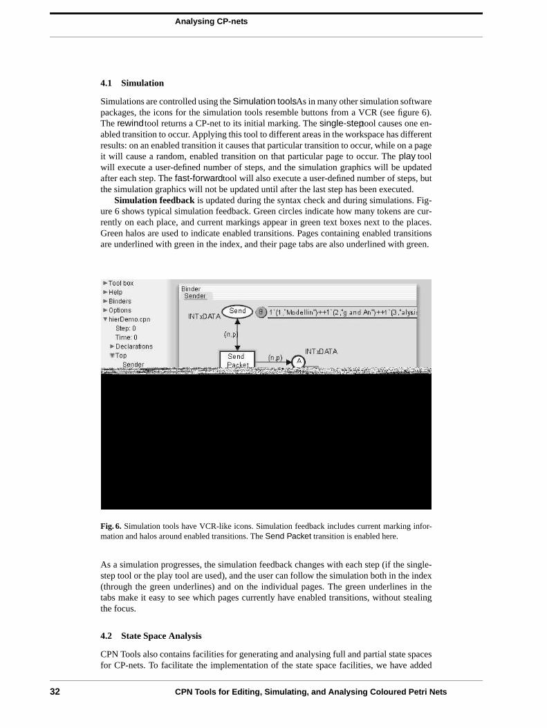
Analysing CP-nets
4.1 Simulation
Simulations are controlled using the Simulation tools. As in many other simulation softwarepackages, the icons for the simulation tools resemble buttons from a VCR (see figure 6).The rewindtool returns a CP-net to its initial marking. The single-steptool causes one en-abled transition to occur. Applying this tool to different areas in the workspace has differentresults: on an enabled transition it causes that particular transition to occur, while on a pageit will cause a random, enabled transition on that particular page to occur. The play toolwill execute a user-defined number of steps, and the simulation graphics will be updatedafter each step. The fast-forwardtool will also execute a user-defined number of steps, butthe simulation graphics will not be updated until after the last step has been executed.
Simulation feedback is updated during the syntax check and during simulations. Fig-ure 6 shows typical simulation feedback. Green circles indicate how many tokens are cur-rently on each place, and current markings appear in green text boxes next to the places.Green halos are used to indicate enabled transitions. Pages containing enabled transitionsare underlined with green in the index, and their page tabs are also underlined with green.
Fig. 6. Simulation tools have VCR-like icons. Simulation feedback includes current marking infor-mation and halos around enabled transitions. The Send Packet transition is enabled here.
As a simulation progresses, the simulation feedback changes with each step (if the single-step tool or the play tool are used), and the user can follow the simulation both in the index(through the green underlines) and on the individual pages. The green underlines in thetabs make it easy to see which pages currently have enabled transitions, without stealingthe focus.
4.2 State Space Analysis
CPN Tools also contains facilities for generating and analysing full and partial state spacesfor CP-nets. To facilitate the implementation of the state space facilities, we have added
32 CPN Tools for Editing, Simulating, and Analysing Coloured Petri Nets

Analysing CP-nets
a few syntactical constraints which are important for state space generation and analysisbut which are unimportant for simulation. For example, a state space cannot be generatedunless all places and transitions in a page have unique names, and all arcs have inscriptions.The syntax checker will locate violations of these constraints, and graphical feedback willassist a user in locating potential problems. CP-nets that do not meet all of the constraintscan still be simulated without problems.
(a) State space tools.
Statistics----------------------
Occurrence GraphNodes: 54Arcs: 1183Secs: 0Status: Partial
Scc GraphNodes: 43Arcs: 1128Secs: 0
(b) Statistics from state space report.
Fig. 7. State space tools from the index and a state space report.
State space tools from the index are shown in figure 7(a). The EnterStateSpacetoolis used first to generate net-specific code necessary for generating a state space, i.e. thestate space code is not generated incrementally as the simulation code is. The CalcSStoolis the tool that generates the state space, while the CalcSCCtool calculates the stronglyconnected component graph of the state space. The user can set a number of options whichwill determine how much of a state space should be generated. For example, it is possibleto stop generating a state space after a certain number of states have been generated or aftera certain amount of time has passed. Options are changed by editing text in the index.
Two tools exist for switching between the simulator and a state space. The SStoSimtoolwill take a user-specified state (all states in the state space are numbered) from the statespace and “move” it to the simulator. This makes it possible to inspect the marking of theCP-net and to see the enabled transitions. It is also possible to simulate the model startingat the state that was moved from the state space. Similarly, the SimtoSStool will “move”the current state of the CP-net in the simulator to the state space. Once a (partial) statespace has been generated, it is possible to seamlessly and instantaneously switch betweenthe state space and the simulator. In figure 7(a), the SStoSim tool is configured to movestate 5 to the simulator. A user can easily edit the text of the state number in order to selectanother state.
Standard state space reports can be generated automatically and saved using the SaveRe-port tool. Such reports contain information about one or more of the following: statisticsabout the generation of the state space, boundedness properties, home properties, livenessproperties and fairness properties. Figure 7(b) shows a state space report containing onlystatistics regarding the generation of the state space.
Querying facilities are also available. The state space facilities of CPN Tools are verysimilar to the facilities in the Design/CPN Occurrence Graph Tool [9] (OG Tool). Thismeans that the standard queries that are described in the user manual for the OG Tool arealso available in CPN Tools. However, currently there is no advanced interface that can beused to access these facilities. The method for accessing these queries is shown in figure 8.A query can be written using the Auxiliary texttool from the Auxiliary tools. The query isthen evaluated by applying the ML Evaluatetool from the Simulation toolsto the auxiliarytext. The result of evaluating the query will be shown in a speech bubble. Currently, thereis no support for drawing state spaces or parts of state spaces.
CPN Tools for Editing, Simulating, and Analysing Coloured Petri Nets 33

Conclusion and Future Work
5.0Conclusion and Future Work
Fig. 8. Evaluating state space queries.
5 Conclusion and Future Work
CPN Tools combine advanced interaction techniques into a consistent interface for editing,simulating, and analysing Coloured Petri Nets. These interaction techniques have proven tobe very efficient when working with Coloured Petri Nets. CPN Tools requires an OpenGLgraphics accelerator and a PC running Windows 2000 or Windows XP. Furthermore, itis recommended that the CPU is at least a Pentium II, 400 MHz (or equivalent) and thatthere is at least 256 MB RAM. Future versions are expected to run on all major platformsincluding, Windows, Unix/Linux and MacOS. Additional information about CPN Tools,can be found at http://www.daimi.au.dk/CPNTools/ .
CPN Tools does not currently provide all of the functionality that is available for De-sign/CPN. Future work will, however, extend the functionality of CPN Tools in severaldifferent ways. Facilities for collecting data, running multiple simulations, and calculatingstatistics are currently being integrated into CPN Tools, and these facilities are expected tobe available by the end of 2003. Additional animation facilities, such as message sequencecharts and domain-specific animation, are also being developed. However, these facilitieswill probably not be available before 2004. Additional plans include the design and imple-mentation of a totally new generation of state space facilities.
Acknowledgements We would like to thank Michel Beudouin-Lafon and Wendy E. Mackaywho played a central role in designing the new interface for CPN Tools. We would also liketo thank current and former members of the CPN Group at the University of Aarhus fortheir participation in the design and implementation of the tool.
References
1. Jensen, K.: Coloured Petri Nets: Basic Concepts, Analysis Methods and Practical Use, Volumes1-3. Monographs in Theoretical Computer Science. Springer-Verlag (1992-1997)
2. Kristensen, L.M., Christensen, S., Jensen, K.: The practitioner’s guide to coloured Petri nets.International Journal on Software Tools for Technology Transfer 2 (1998) 98–132
3. Design/CPN. Online: http://www.daimi.au.dk/designCPN/.4. Petri Nets Tool Database. Online: http://www.daimi.au.dk/PetriNets/tools/db.html.5. CPN2000 Project. Online: http://www.daimi.au.dk/CPnets/CPN2000/.6. Kurtenbach, G., Buxton, W.: User learning and performance with marking menus. In: Proceedings
of Human Factors in Computing Systems, ACM (1994) 258–264 CHI’94.7. Bier, E., Stone, M., Pier, K., Buxton, W., Rose, T.D.: Toolglass and magic lenses: the see-through
interface. In: Proceedings of ACM SIGGRAPH, ACM Press (1993) 73–808. Standard ML of New Jersey. Online: http://cm.bell-labs.com/cm/cs/what/smlnj/.9. Jensen, K., Christensen, S., Kristensen, L.M.: Design/CPN Occurrence Graph Man-
ual. Department of Computer Science, University of Aarhus, Denmark. (1996) Online:http://www.daimi.au.dk/designCPN/man/.
34 CPN Tools for Editing, Simulating, and Analysing Coloured Petri Nets

Introduction
1.0Introduction
Complement pour presentation outil fko
Yann Thierry-Mieg , Fabrice Kordon, Emmanuel Paviot-Adet, & DenisPoitrenaud
(LIP6-SRC, France)
Laboratoire d•Informatique de Paris 6, France [email protected],[email protected], [email protected],
Keywords: Well-Formed Petri nets, symmetry detection, symbolic model-checking
Abstract.
1 Introduction
Researches in the area of Modeling of Parallel Systems aim at veri“cation, co-herence and speed up of systems development, starting from requirement cap-ture, high level and low level speci“cation up to “nal prototyping. These goalsare achieved through veri“cation, translation and re“nement of formal models.They can be applied to large dynamic information systems.
Formal modeling is a key issue for veri“cation of system speci“cations andhas to deal with the always-growing industrial needs. Formalisms such as Petrinets have been systematically improved, so Colored Petri nets are now widelyused for parallel and distributed systems.
However, to be operated on large speci“cations and to be an e�cient help tosystem designers, techniques have to be implemented by CASE tools. This paperpresents CPN-AMI, a Petri net based CASE environment for the veri“cation ofparallel systems.
CPN-AMI brings together a large collection of tools implemented in various
CPN-AMI 2.6 35

CPN-AMI2.6: a Petri net based CASE environment
2.0CPN-AMI2.6: a Petri net based CASE environment
2.1 Architecture of CPN-AMI
CPN-AMI is a collection of tools federated in FrameKit [7, 14], a generic CASEenvironment o�ering both integration capabilities and an enhanced developmentenvironment. As all CASE environments generated from FrameKit, CP-AMIo�ers a user-friendly access to Petri net services through a unique user interface:Macao [15].
The tools implemented in our team are based on the FrameKit API librariesthat ensure an automatic integration in FrameKit.
We have coupled with a driver the tools developed in other universities andthen imported to be a part of CPN-AMI 2. A driver is a piece of code thatprepares required data to be processed by the tool, invokes it and then forwardsresults to the user interface. Drivers are implemented using the FrameKit APIs.
This architecture is one of the strongest points in CPN-AMI. It enables anenrichment process taking bene“ts of other developments to propose a uni“edPetri net based environment. Enrichment of the successive versions of CPN-AMIwas done at an extremely low development cost [7].
2.2 Tools in CPN-AMI
The currently released CPN-AMI 2.5.1 already o�ers numerous services:
– Modeling tools:• Syntactic veriÞer: checks the AMI-Net syntax and transform the Petri
net into various internal representation for a large number of tools.• Modular Petri net assembling: this tool is built to help designer to as-
semble modules communicating either by means of places or by meansof transitions. The users select a group of objets and then, merge themto one equivalent object if it is possible (for example, color domains arethe same for places).
• Pretty Petri Nets : this service aims to rearrange ŽspaghettiŽ Petri nets.This service has been made to be exploited by other Petri net services(like CPN-Unfolder, Pre“x or reachability graph display). However, itcan be directly invoked by a user. This service relies on DOT [4].
• Suppression of 0-bounded places and non-Þrable transitions: uses thebound of place service to suppress 0-bounded places and transitions withthose places as precondition. Mainly used with structural analysis in or-der to limit the study to the useful part of the net.
– Simulation and debugging:• Colored Petri net simulator : in this tool, we have attempted to keep, as
more as possible, the analogy with programming language debuggers. Toachieve this goal, the user may use di�erent execution modes, break pointpossibilities, data extractions during the execution and external treat-ments associated to transition. Standard debugging functions are alsoavailable like intermediate state management (including load and saveoperations) and con“guration management (a con“guration is a set ofsimulation parameters: scripts de“nitions, observation net, intermediatestate).
36 CPN-AMI 2.6

CPN-AMI2.6: a Petri net based CASE environment
– Computation of structural properties:• Place invariants: computation of P-SemiFlows using a service from Great-
SPN [6],• Colored place invariants: this tool computes invariants using a adapted
version of the general algorithm [2]. It is one of the very few implementedones.
• Transition invariants : computation of T-SemiFlows using a service fromGreatSPN.
• Siphon and deadlocks: they can be computed using a service from Great-SPN or using a BDD [5] based implementation.
• Bounds of places: this tool computes lower and upper structural bounds.The calculus is based on the state equation and uses linear programmingtechniques. As a consequence, the computed bounds (higher and lower)may not be the best ones, but this tool may be useful to quickly highlightsome major problems in the model. For colored models, this tool can beaccessed via P/T unfolding. This service is based on lpsolve [11].
• Linear properties characterization: the aim of this tool is to compute alinear characterization of the reachability set. When the resulting lin-ear constraints system exactly describes the reachability set, a messagewarns the user.
• Liveness computation for safe (1-bounded) nets: computes if the net islive (from any reachable state and for any transition it is possible toreach a state from which the transition is “rable).
– Computation of behavioral properties:• Generation of the reachability graph, CTL and LTL queries evaluation:
this tool is based on PROD [16]. The proposed encapsulation let users ac-cess to prede“ned services such as detecton of deadlocks but also enablesaccess to advanced funtioncs to evaluate CTL or LTL formulae
• Generation of the reachability graph, CTL and LTL queries evaluation(alternative) : this tool is based on LoLA [12]. The proposed implementa-tion let users access to a set of prede“ned services (some are not o�eredin PROD such as the reversibility of a net). It also enables the evaluationof temporal logic queries.
• Boolean formula on reachability graph: this tool computes a set of mark-ings containing the reachability set. In this set, places are just consideredas ?marked? or ?unmarked?. The results are displayed as properties overthe net. This service uses BDDs [5] to compute the marking set.
• McMillan unfolding : this service computes an unfolding for a safe net(safety is not veri“ed by the tool). This software has been developed byS. Romer and implements the algorithm de“ned by J. Esparza, S. Romerand W. Vogler in [10]. This tool is also part of PEP [9].
– Unfoldings:• Colored Petri net unfolding: transforms a colored Petri net into a Place/Tran
Petri net. The resulting net is a new model that can be displayed andanalyzed. An option allows to suppress 0-bounded places and non-“rabletransitions. This option uses a heuristic to compute those places (it is
CPN-AMI 2.6 37
New tools for CPN-AMI 2.6
3.0New tools for CPN-AMI 2.6
not based, like the ?suppression of 0-bounded places and non-“rabletransitions? service, on linear programming). Another option allows tocompute a pretty layout of the resulting net.
3 New tools for CPN-AMI 2.6
Version 2.6 of CPN-AMI, to be released in the second half for 2003, includesnew original tools to be demonstrated as a preliminary version in the 2003 PetriNet conference.
3.1 DDD -based Model Checking
This tool is based on Data Decision Diagram (DDD), a new data structurepresented in [3], for the representation of the state space.
DDDs, similary to Binary Decision Diagrams, are sharing direct acyclic graphswhere nodes represents variables and arcs the values a�ected to them. The mainadvantages of this data structure are: there is no hypothesis on variable domains,there is no constraint on the variable order, it can code dynamic structures(stack, “fo, etc.).
They are equiped with internal operators which can be seen as set operators.Moreover, the user has the capacity to enrich functionnalities by de“ning speci“coperators. This data structure has been used to model-check VHDL programsas well as extended Petri nets. The tool integrated in CPN/AMI allows theveri“cation of safety properties.
3.2 Symbolic model checking based on Well-Formed Nets
We present in the Petri-Net 2003 conference a new tool which automaticallydetects the symmetries of a model [17], and allows their exploitation throughgeneration of an equivalent Well-Formed Net [8]. Well-Formed Nets allow au-tomatic construction of a Symbolic Reachability Graph (SRG) [1] that groupsstates according to an equivalence relation.
It relies on the tool GreatSPN 2.0 [6] of the University of Torino for theconstruction of this graph.
The size of the obtained graph is at worst the same as that of the concretereachability graph, but if the model presents global symmetries the size of theSRG may be exponentially smaller. This technique is particularly adapted formodels presenting large color domains, as the size of the RG is generally combi-natorial on the size of color domain, but the SRG can yield linear size increase.
This tool currently o�ers deadlock and home-state detection, and LTL model-checking on the SRG is being implemented and thus may be available at the timeof this tool presentation.
38 CPN-AMI 2.6

References
4.0References
References
1. G. Chiola, C. Dutheillet, G. Franceschinis, and S. Haddad. A symbolic reachabilitygraph for coloured Petri nets. Theoretical Computer Science, 176(1…2):39…65, 1997.
2. J-M. Couvreur. The general computation of ”ows for coloured nets. In ICATPN ,pages 204…223, June 1990.
3. J-M. Couvreur, E. Encrenaz, E. Paviot-Adet, D. Poitrenaud, and P-A. Wacrenier.Data decision diagrams for petri net analysis. In ICATPN , volume 2360 of LNCS,pages 101…120. Springer-Verlag, June 2002.
4. E. Koutso“os and S.C. North. Drawing graphs with dot. Technical report, Tech-nical report, AT&T Bell Laboratories, Murray Hill, NJ, 1993.
5. J. Cortadella E. Pastor, O. Roig and R.M. Badia. Petri net analysis using booleanmanipulation. In ICATPN , volume 815 of LNCS, pages 204…223. Springer-Verlag,June 1994.
6. GreatSPN: GRaphical Editor, Analyzer for Timed, and Stochastic Petri Nets. url: http://www.di.unito.it/~greatspn/ .
7. F. Kordon and J-L. Mounier. FrameKit, an Ada Framework for a Fast Implemen-tation of CASE Environments. In ACM/SIGAda ASSET’98 symposium , pages42…51, July 1998.
8. G. Franceschinis G. Chiola, C. Dutheillet and S. Haddad. Stochastic well-formedcolored nets and symmetric modeling applications. IEEE Transactions on Com-puters, 42(11):1343…1360, 1993.
9. PEP Homepage. url : http://parsys.informatik.uni-oldenburg.de/~pep .10. S. Roemer J. Esparza and W. Vogler. An improvement of mcmillan•s unfolding
algorithm. In Tools and Algorithms for the Construction and Analysis of Systems ,volume 1055 of LNCS, pages 87…106. Springer-Verlag, March 1996.
11. The lp solve web site. url : http://sal.kachinatech.com/B/3/LP_SOLVE.html .12. The LoLA o�cial web site. url : http://www.informatik.hu-berlin.de/
~kschmidt/lola.html .13. The CPN-AMI Home page. url : http://www.lip6.fr/cpn-ami .14. The FrameKit Home page. url : http://www.lip6.fr/framekit .15. The Macao Home page. url : http://www.lip6.fr/macao .16. Home page of PROD. url : http://www.tcs.hut.fi/Software/prod .17. Y. Thierry-Mieg, C. Dutheillet, and I. Mounier. Automatic symmetry detection in
well-formed nets. In ICATPN 2003 , LNCS. Springer-Verlag, June 2003.
CPN-AMI 2.6 39

References
40 CPN-AMI 2.6

Business Process Manager
1.0Business Process Manager
Business Process Manager
Automate
StreamlineOptimize
Any Business Process
Drive Streamlined Decisions – Faster.
FileNET 41

Business Process Manager
Streamline the accountspayable process to handlemore invoices quickly, easily,and accurately to improvecashflow and fiscalresponsibility.
Capture and review aninsurance policy in minutesand automate the flow of thepolicy through differentdepartments to improveemployee efficiency andreduce the per-policy cost.
Seamlessly integrate legacysystems into your financialbusiness processes,maximizing the value ofexisting investments.
�È
FileNet Corporation 3565 Harbor Boulevard, Costa Mesa, CA, USA 92626-1420Phone: 800.FileNet (345.3638) Outside the U.S. call: +1.512.434.5935 www.filenet.com
Business Process Manager
page 2
Processes are the paths of decision making –some are simple, others complex, and hundredsweave through your business every day. They setthe pace of your operations. Managing the flow ofwork, and information, along these process pathsdetermines the speed, agility, and quality ofdecision making. That is why streamlining andoptimizing these processes determines thesuccess of your organization.
Processes involve people, business systems, and content. Onlywhen they work together in an automated environment canmaximum productivity and value be realized. Furthermore, optimizedprocesses strengthen your ability to react quickly to changingmarket conditions and customer requests while ensuring regulatorycompliance. Bottom line, better processes continuously improve andenhance the performance of your business to give you a competitiveadvantage.
Many challenges need to be overcome before these objectives canbe met. Many existing processes are still donemanually, making them difficult to integrate andstandardize. They are not easy to modify whenconditions change. In addition, a large numberof complex processes rely on content fromdisconnected systems that cannot shareinformation. All of this limits productivity, slowscycle and response times, hinders regulatorycompliance, and makes it difficult to accuratelyaccount for how decisions are made.
Companies utilizing the right Business ProcessManagement capabilities are conquering thesechallenges to gain a true competitive edge byautomating, integrating and optimizing repetitive
critical business processes at every level of their organization. Theyare doing so with FileNet Business Process Manager.
Lack of decision-making processes:Only 21% of companieshave processes forprioritizing andmanaging theirtechnology. Most maketheir decisions ad hoc,favoring the petprojects of powerfulmanagers.
Optimize Magazine,Nov. 2002
With FileNet BusinessProcess Manager, you can…
42 FileNET

Business Process Manager
Streamline the process ofreviewing loan applicationsto reduce response timefrom days to just minutes,improving customer servicelevels.
Automate the fulfillment ofvital records requests torespond to constituentsmore quickly and withgreater accuracy.
Move claims cases fromdiscovery to settlementquickly by implementingspecific business rules tofacilitate faster resolutionand higher claimsprocessing efficiency.
�È
FileNet Corporation 3565 Harbor Boulevard, Costa Mesa, CA, USA 92626-1420Phone: 800.FileNet (345.3638) Outside the U.S. call: +1.512.434.5935 www.filenet.com
Business Process Manager
page 3
The Path to Better DecisionsFileNet Business Process Manager controls the flow of work throughoutyour business by streamlining, automating, and optimizing businessprocesses. It has the flexibility and scalability to handle the most complexbusiness processes – involving millions of transactions, thousands ofusers, and multiple business applications.
Business Process Manager helps shorten process lifecycles andautomatically manages process exceptions so you can react immediatelyto internal events or customer demands. While powerful, it is also easy touse, administer, and deploy. Business analysts can modify processes andapply new business rules immediately. Best practices and business logiccan be captured and reused thereby shortening implementation time andincreasing your speed-to-market so you can seize new businessopportunities.
Business Process Manager monitors and tracks business processes soanalysts and managers can see how their operations are performing. This, in turn, helps you simulate and optimize key processes and the valueof internal resources. By integrating content with business processes, alllevels of your organization can make timely decisions based on the mostaccurate information available.
These capabilities have delivered a significant return on investment for ourcustomers including benefits such as:
• improving productivity by 140%
• decreasing decision cycle time from 7 days to just 7 minutes
• automating the monthly payment of over 30,000 invoices to streamlineoperations and take full advantage of early-payment discounts
• reducing Human Resources costs by $1 million by providing employeeswith automated services and self-serve resources
• saving $3 million a year by driving high-performance processes andoptimized work ow throughout the organization.
A Platform for Tomorrow, Today
Business Process Manager is based on the FileNet P8 standards-basedarchitecture, which offers enterprise-level scalability and flexibility tohandle the most demanding content challenges, the most complexbusiness processes, and integration to all your existing systems. TheFileNet P8 architecture provides a scalable framework for functionalexpansion to manage enterprise content and Web publishing challenges,and provide greater process control and consistency across yourenterprise.
With FileNet BusinessProcess Manager, you can…
FileNET 43

Business Process Manager
Event-Driven Processing �Æ Increases the agility andresponsiveness of business operations byautomatically responding to transactions or businessevents as they occur.
Process Versioning & Easy Administration �ÆSupports rapid deployment of improved processeswhile minimizing the impact on normal operations.
Process Tracking, Analysis & Simulation �Æ Ensuresbetter business decisions by monitoring workflow,providing in-depth analysis of live and historicalprocess information, and validating processmodifications before they are deployed.
Reusable Process Definitions �Æ Enables rapiddeployment best practices, ensures consistentprocessing, and lower TCO by reusing processdefinitions.
Process Timers �Æ Maintains faster cycle times byescalating work on time-based applicationsrequirements.
Process Power & Scalability �Æ Handles a wide rangeof business processes including complex processesthat involve millions of transactions and tens ofthousands of users.
Fully Integrated Out-of-the-Box Content Management�Æ Seamlessly manages, stores, and shares contentthat is part of the business process without the burdenof integrating 3rd-party tools or custom programming.
Combining Automation, Integration and Optimization for Increased Business Performance
Application Integration �Æ Improves responsivenessand decision making by integrating with businessapplications and enterprise content via SOAP, XML,and Enterprise Application Integration.
Graphical Process Design & Modeling Tool �Æ Easilydefines, designs, and administers business processesfor both business and IT users.
100% Web Based �Æ Delivers a high level of easilyaccessible process functionality while minimizingdeployment costs.
Process Flexibility �Æ Provides a rich processdefinition environment that can accurately implementhighly complex, interrelated processes withcomprehensive functionality.
Standards Based �Æ Protects investments byintegrating with other infrastructures using industrystandards (J2EE, XML).
Rules Engine Integration �Æ Flexibly incorporates andchanges business rules that apply to processes byintegrating with an industry leading Business RulesEngine.
Out-of-the-Box End-User Process UI �Æ Enables you torapidly implement tailored BPM solutions through afully functional and customizable user interface.
Business Process Manager
FileNet Corporation 3565 Harbor Boulevard, Costa Mesa, CA, USA 92626-1420Phone: 800.FileNet (345.3638) Outside the U.S. call: +1.512.434.5935 www.filenet.com
44 FileNET

Business Process Manager
Business Process Manager
FileNet Corporation 3565 Harbor Boulevard, Costa Mesa, CA, USA 92626-1420Phone: 800.FileNet (345.3638) Outside the U.S. call: +1.512.434.5935 www.filenet.com
Platform Base
Accelerated Decision MakingThe moment of decision happens thousands of times a day andeach moment affects the velocity of your business. By streamliningand automating critical processes, FileNet Business ProcessManager allows you to optimize your operations and improve yourability to make fast and accurate decisions while:
• Reducing cycle times and improving productivity across theentire organization
• Lowering total cost of ownership by connecting users andapplications with a unified business process managementinfrastructure
• Enabling the "real-time enterprise" by allowing users to betterreact to business events as they occur
Operating Systems: • Microsoft Windows 2000, • Sun Solaris
Databases: • Microsoft SQL Server• Oracle
J2EE Application Servers:• BEA Weblogic• IBM WebSphere
Browsers: • Microsoft Internet Explorer• Netscape
Process• Workflow Management• Document Review & Approval• Process Tracking• Process Analyzer• Process Simulation• Process DesignersContent• Library Services• Classification• Browse & Search• HTML, PDF Renditions• Events• Lifecycle Management• PublishingConnectivity• Workplace UI• Microsoft Office & WebDAV
Integration• Portal Integration• XML Integration
� Additional Process Designers
FileNet Expansions
Business Process Manager provides comprehensive process management along with advancedanalytics and simulation. Expanded ECM capabilities can be easily added for managing Web content,large volumes of fixed documents, and for enhanced content management and connectivity.
�È
page 5
� Capture Desktop
� Business Integration (EAI)
� Image Services ResourceAdapter (ISRA)
� Web Content Management
FileNET 45

Business Process Manager
�È
Business Process Manager
page 6
FileNet Enterprise Content Management (ECM) solutions are designedto help companies manage the content and business processes thatmust come together to improve the way decisions are made – byindividuals, across project teams and departments. Based on theFileNet P8 architecture, these solutions provide a unified platform formanaging content, processes, and integration to existing systems fora wide range of business applications, creating real processefficiencies and providing a scalable architecture for expansion.
FileNet Business Process Manager is an ECM solution that allowscompanies and government agencies to automate, streamline, andoptimize their complex business processes. With this solution,processes supporting millions of transactions and thousands of userscan be quickly deployed and immediately modified so companies canbetter respond to changing conditions.
About FileNetFileNet Corporation (NASDAQ: FILE) can help organizations make betterdecisions by managing the content and processes that drive theirbusiness. FileNet’s Enterprise Content Management (ECM) solutionsallow customers to build and sustain competitive advantage bymanaging content throughout their organizations, automating andstreamlining their business processes, and providing the full-spectrumof connectivity needed to simplify their critical and everyday decisionmaking.
FileNet ECM solutions deliver a comprehensive set of capabilities thatintegrate with existing information systems to provide cost-effectivesolutions that solve real-world business problems.
Since our founding in 1982, 3,800 organizations, including 80 of theFortune 100, have taken advantage of FileNet solutions for help inmanaging their mission-critical content and processes.
Headquartered in Costa Mesa, Calif., the Company markets itsinnovative ECM solutions in more than 90 countries through its ownglobal sales, professional services and support organizations, as well asvia its ValueNet® Partner network of system integrators, value-addedresellers, and application developers.
FileNet Corporation 3565 Harbor Boulevard, Costa Mesa, CA, USA 92626-1420Phone: 800.FileNet (345.3638) Outside the U.S. call: 512.434.5935 FileNet is a registered trademark of FileNet Corporation. © 2003 FileNet Corporation. All Rights Reserved. 1202/1496 www.filenet.com
46 FileNET

Flower
1.0Flower
CASE HANDLING & WORKFLOW MANAGEMENTPROFESSIONALLY-ORIENTATED SUPPORT
FOR PRODUCTION AND KNOWLEDGE WORKERSIN ADMINISTRATIVE ENVIRONMENTS
GETTING IT RIGHT!
FLOWer 47

Flower
THE RESULT?
Your business processes carried out perfectly.Your professionals committed.
Your web site integrated with your processes.Your customers satisfied.Your flexibility optimised.
Your continuity guaranteed.Your growth supported.
•A case is presented,a colleague is consulted about the case,
the customer is advised of the status of the casethe case is transferred,
the case passes through the organisation,the objective is achieved!Ž
CASE HANDLING& WORKFLOWMANAGEMENT
48 FLOWer

What is FLOWer?
2.0What is FLOWer?
WHAT IS FLOWer?
� FLOWer is based on a new concept: case hand-ling.� FLOWer manages and supports the execution ofactivities in the context of a specific case (folder,event, incident).
THE POWER OF FLOWER:
� Simplicity;� Flexibility in process handling;� Insight into the whole, at any time;� Work notification;� Ability to retrieve cases;� Monitoring of progress and deadlines;� Detailed control and management information;� Short implementation time;� Extensive integration options;� Full integration with the Internet;� Scalability.
WHY WAS FLOWER DEVELOPED?
� FLOWer was developed from the realisationthat in office environments both production andknowledge-intensive activities take place, oftenwithin the same process. In other words, withina process whilst the bulk of the work follows aconsistent route, there may be frequent exceptions.The exception becomes the rule, but within agreedbusiness perameters. Flexibility is therefore key inthese environments.
� Further, the focus is on the case and not on theactivity. The process flow depends strongly on thecase and it is essential to have insight into thewhole at all times. This also applies to customers -they want to be able to view the progress of theircase at any moment.
� FLOWer focuses on the case while also providingthe necessary flexibility.
FLOWer, getting it right!
CASE HANDLING& WORKFLOWMANAGEMENT
FLOWer 49

What is FLOWer?
•Employees have no overview of their casesand often don•t know which activities they should carry out in a particular case.Ž
•Employees lack flexibility in handling their cases.Ž
•There is far too much work involved in processing exceptions.Ž
Žt isn•t possible to advise a customer of the status straight away.Ž
•Only part of the business process has been automated. And the web site doesn•tcomply with this.Ž
•Various locations use the same applications; it isn•t possible to tailor theseto the respective organisation in each location.Ž
•The time it takes new staff to become familiar with the applications is 3 to 6 months.Ž
•Applications support either only experienced or only new users.Ž
•Knowledge workers give up because the applications are registrative and do notsupport the actual work.Ž
•The payback period of the applications is longer than a year.Ž
FLOWer, the solution for your business problems!
CASE HANDLING& WORKFLOWMANAGEMENT
50 FLOWer

Broad Application
3.0Broad Application
BROAD APPLICATION
� FLOWer has a very broad application inadministrative, knowledge-intensive organisationswhere:� The focus is on processing case-specific matters� (folders, events, incidents);� There is a strong need for flexibility and adapta-� bility;� It is also necessary to be able to support pro-� duction activities.
EXCELLENT START WITH PROTOS
� If you are using our product PROTOS, you willalready have defined and optimised your proces-ses. From this basis, you can implement them inFLOWer. � So, as well as having knowledge and informa-tion about your processes, with FLOWer you arealso sure of getting it right!
EXAMPLES
� Processing benefit payments, handling objec-� tions and complaints.� Banks and insurance companies (credit facilities,� claims handling, fraud management).� Government bodies (processing objections to � � property tax levies, issuing licences, processing � naturalisation requests).� Telecommunications (customer and contract � administration).� Housing corporations (property administration).� Educational institutions (student and course � administration).� Health Care sector (patient registration and � administration).� Police (support for police fieldwork).� Courts (summonses).� IT companies and IT departments (helpdesk sup� port).
FLOWer, getting it right!
CASE HANDLING& WORKFLOWMANAGEMENT
FLOWer 51

Broad Application
CASE HANDLING& WORKFLOWMANAGEMENT
You can also do this for rolesƒIn the FLOWer Studio you can define a processsimply, using graphics.
52 FLOWer

Functionality
4.0Functionality
CASE HANDLING& WORKFLOWMANAGEMENT
FUNCTIONALITY
� Process design: FLOWer Studio
In the FLOWer Studio, a graphic design environ-ment, a process can be fully designed:� Process routing;� Roles;� Data;� Forms.
� In the FLOWer Studio you can design your� formsany way you like.
� Organisational design: FLOWer Management
FLOWer also includes a graphic environmentfor designing the organisation. Here, the followingcan be defined:� Users (and user groups);� Work profiles;� Authorisation profiles or functions;� Queues;� Queries.
� Changes in the organisation model can becarried out in real time without having to change the process model.
FLOWer, getting it right!
FLOWer 53

Functionality
CASE HANDLING& WORKFLOWMANAGEMENT
The FLOWer Case Guide gives insight intothe entire context.
Employees are allocated a case or can call upa case themselvesƒ
54 FLOWer

Functionality
CASE HANDLING& WORKFLOWMANAGEMENT
� Execution: FLOWer Client
� After the process and organisational designphase, the employees can start to work on thecases. They are allocated cases or can call themup themselves.
� When a case is opened the Case Guide isdisplayed. This gives the employee a direct viewof:� The activities to be carried out at that moment;� The pending activities still to be handled;� The activities that have already been handled.
� Flexibility is crucial. If they are authorised, theemployees can redo, or skip activities. It is alsopossible to carry out activities that are not yet duefor execution.
� Steering: FLOWer Management Information
� FLOWer records the entire history of a case andoffers extensive options in the area of manage-ment information.
� If an activity is connected to a form, that form is � opened when the activity is carried out.� This allows the user to see immediately which � fields are compulsory.
FLOWer, the user in control!
FLOWer 55

Functionality
CASE HANDLING& WORKFLOWMANAGEMENT
GETTING IT RIGHT...
Case Handling with FLOWer offers a flexible and controlled approachto business workflows. Understand the possibilities and see it for yourself by
arranging an in-house demonstration.
56 FLOWer

Implementation Approach
5.0Implementation Approach
CASE HANDLING& WORKFLOWMANAGEMENT
IMPLEMENTATION APPROACH
� Based on a phased project approach, FLOWermakes dynamic, evolutionary development possi-ble, together with all disciplines and people invol-ved in the process.
The Result? A system:� That is geared to the needs and wishes of
the users;� That provides optimal support for your business
processes!
The time to implement? With FLOWer, an ope-rational application can be produced within onemonth after commencement.
USE OF PROTOS
To implement FLOWer, our product PROTOS isused. PROTOS is a powerful tool for describing,analysing and redesigning business processes.
This allows the implementation time to be consi-derably reduced. From the very outset, there iscommitment and conformity!
BUSINESS PARTNERS
For the implementation of FLOWer, PallasAthena has concluded joint agreements with busi-ness partners. Like Pallas Athena, these partnersoffer:� An exceptional quality of service;� A process-orientated approach;� A dedicated organisation and staff.
Getting it right … also with our business partners!
GETTING IT RIGHT!
FLOWer 57

Implementation Approach
www.pallas-athena.comVisit our web site for up-to-date and extensive information.
Pallas Athena www.pallas-athena.com
GETTING IT RIGHT!
58 FLOWer

![Boualem Boashash, Ghasem Azemi, and John M. O’Toole Time …otoolej.github.io/pubs/PDFs/ieee_SPM_Nov2013.pdf · 2015-10-12 · IEEE SIGNAL PROCESSING MAGAZINE [110] NOVEMBER 2013](https://static.fdocuments.in/doc/165x107/5e7aa1ed75f338485c3d0842/boualem-boashash-ghasem-azemi-and-john-m-oatoole-time-2015-10-12-ieee-signal.jpg)