
TOOL BITS - 青岛优先出锐工具有限公司 bits.pdfCARBIDE ROUND TOOL BITS E 283 END MILL...
12
TOOL BITS
Transcript of TOOL BITS - 青岛优先出锐工具有限公司 bits.pdfCARBIDE ROUND TOOL BITS E 283 END MILL...

TOOL BITS
E 281
TOOL BITSSELECTION GUIDE
B1320B2320B4320
HSS, COBALT 5%, YPM ROUND TOOL BITS E 282
B6320 CARBIDE ROUND TOOL BITS E 283
E 285 ~ E290END MILL TECHNICAL DATA
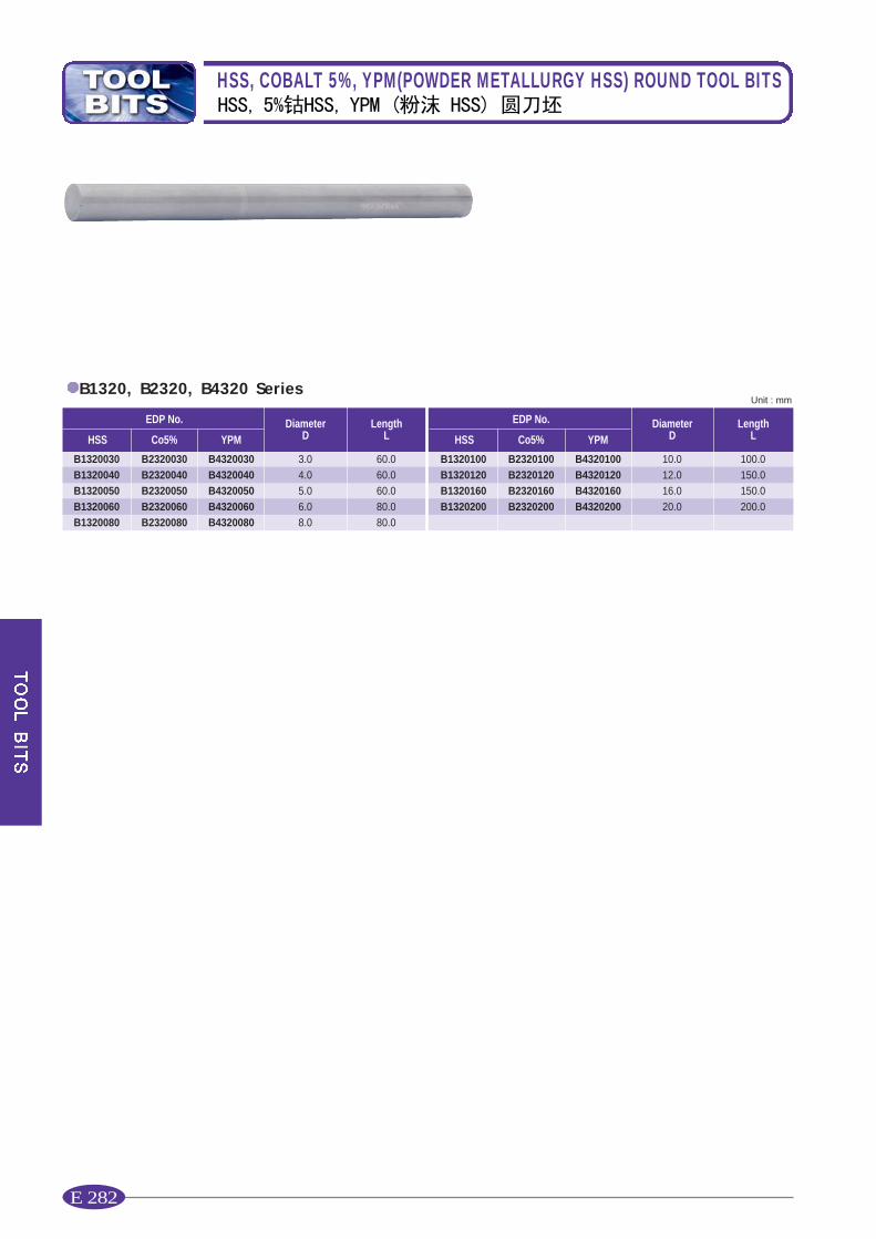
HSS, COBALT 5%, YPM(POWDER METALLURGY HSS) ROUND TOOL BITS
E 282
EDP No. DiameterD
LengthLHSS Co5% YPM
B1320030B1320040B1320050B1320060B1320080
B2320030B2320040B2320050B2320060B2320080
B4320030B4320040B4320050B4320060B4320080
3.04.05.06.08.0
60.060.060.080.080.0
Unit : mmB1320, B2320, B4320 Series
EDP No. DiameterD
LengthLHSS Co5% YPM
B1320100B1320120B1320160B1320200
B2320100B2320120B2320160B2320200
B4320100B4320120B4320160B4320200
10.012.016.020.0
100.0150.0150.0200.0
E 283
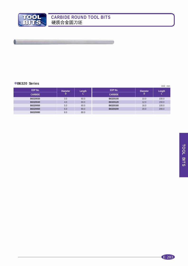
CARBIDE ROUND TOOL BITS
EDP No. DiameterD
LengthLCARBIDE
B6320030B6320040B6320050B6320060B6320080
3.04.05.06.08.0
60.060.060.080.080.0
Unit : mmB6320 Series
EDP No. DiameterD
LengthLCARBIDE
B6320100B6320120B6320160B6320200
10.012.016.020.0
100.0150.0100.0200.0

E 285
TECHNICAL DATA
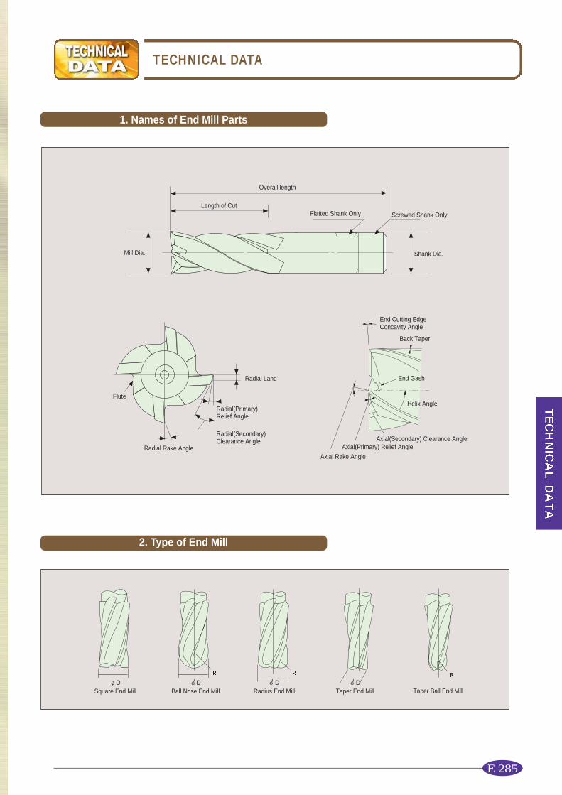
Overall length
Flute
Radial Rake Angle
DSquare End Mill
DBall Nose End Mill
DRadius End Mill
DTaper End Mill Taper Ball End Mill
Radial Land
Radial(Primary)Relief Angle
End Cutting EdgeConcavity Angle
Back Taper
End Gash
Helix Angle
Axial(Secondary) Clearance AngleAxial(Primary) Relief Angle
Axial Rake Angle
Radial(Secondary)Clearance Angle
Screwed Shank Only
Shank Dia.Mill Dia.
Length of CutFlatted Shank Only
1. Names of End Mill Parts
2. Type of End Mill

E 286
TECHNICAL DATA
Feed is usually measured in milimeters per minute. It is the product of feed per tooth times revolution per minute times the number ofteeth in the cutter. Due to variation in cutter sizes, numbers of teeth and revolutions per minute, all feed rates should be calculated fromfeed per tooth.Feed per tooth is the basis of all feed rates per minute, whether the cutters are large or small, fine or coarse tooth, and are run at high orlow peripheral speed. Because feed per tooth affects chip thickness. It is a very important factor in cutter life.Highest possible feed per tooth will usually give longer cutter life between grinds and greater production per grind. Excessive feeds mayover load the cutter teeth and cause breakage or chipping of the cutting edges. The following factors should be kept in mind when usingthe recommended starting feed per tooth.
Speed, feed and depth of cut are the most important factors to consider forbest results in milling. Improper feeds and speeds often cause lowproduction, poor work quality and damage to the cutter.This section covers the basic principles of speed and feed selection formilling cutters and end mills.It will serve as a guide in setting-up new milling jobs.
REVOLUTION
DEPTH OF CUT FEED
INTERRELATIONSHIP OF THREE FACTORS
In milling, SPEED is measured in peripheral feet perminute.(revolution per minute times cutter circumference in feet)This is frequently referred to as �peripheral speed� �cutting speed� or�surface speed�.
Revolutions per Minute N =V : Cutting Speed(m/min)D : Diameter of Tool(mm)N : Revolution per minute(rev/min)
: 3.1416They will have to be tempered to suit the conditons ON THE JOB. For example:
Hard materialsTough materialsAbrasive materialsHeavy cutsMinimum tool wearMaximum cutter life
1000VD
Use Lower Speed Ranges For
Softer materialsBetter finishesSmaller diameter cuttersLight cutsFrail work pieces or set-upsHand feed operationsMaximum production ratesNon-metallics
Use Higher Speed Ranges For
3. SPEEDS
4. FEEDS
E 287
TECHNICAL DATA
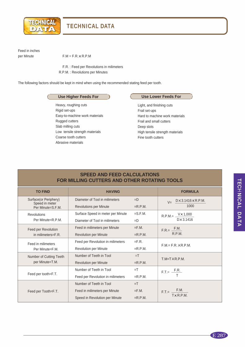
Heavy, roughing cutsRigid set-upsEasy-to-machine work materialsRugged cuttersSlab milling cutsLow tensile strength materialsCoarse tooth cuttersAbrasive materials
Light, and finishing cutsFrail set-upsHard to machine work materialsFrail and small cuttersDeep slotsHigh tensile strength materialsFine tooth cutters
Feed in inches per Minute F.M = F.R. R.P.M
F.R. : Feed per Revolutions in milimetersR.P.M. : Revolutions per Minutes
The following factors should be kept in mind when using the recommended stating feed per tooth.
SPEED AND FEED CALCULATIONSFOR MILLING CUTTERS AND OTHER ROTATING TOOLS
TO FIND FORMULAHAVING
Surface(or Periphery)Speed in meterPer Minute=S.F.M.
RevolutionsPer Minute=R.P.M.
Feed per Revolutionin milimeters=F.R.
Feed in milimetersPer Minute=F.M.
Number of Cutting Teethper Minute=T.M.
Feed per tooth=F.T.
Feed per Tooth=F.T.
V= D 3.1416 R.P.M.1000
R.P.M.=
F.R.=
F.M.= F.R. R.P.M.
T.M=T R.P.M.
F.M.R.P.M.
F.T.= F.R.T
F.T.= F.M.T R.P.M.
Use Higher Feeds For Use Lower Feeds For
Diameter of Tool in milimeters =D
Revolutions per Minute =R.P.M.
Surface Speed in meter per Minute =S.F.M.
Diameter of Tool in milimeters =D
Feed in milimeters per Minute =F.M.
Revolution per Minute =R.P.M.
Feed per Revolution in milimeters =F.R.
Revolution per Minute =R.P.M.
Number of Teeth in Tool =T
Revolution per Minute =R.P.M.
Number of Teeth in Tool =T
Feed per Revolution in milimeters =R.P.M.
Number of Teeth in Tool =T
Feed in milimeters per Minute =F.M.
Speed in Revolution per Minute =R.P.M.
V 1,000D 3.1416

E 288
TECHNICAL DATA
When the product finish become worse, the cutting edge must get dulled, chips become smallerand the cutting sound gets louder. In such cases, a end mill must be resharpened. The followingare the damages of end mills when the resharpening is required.
Cutters should be sharpened as soons as the wear land(Fig. 2.) reaches a predetermined width.This width should permit sharpening without excessive loss of tool life. It may vary from a fewthousandth to 1/16 inch, depending on the type of cutter and the finish required on the product.This method is used on production runs where uneven amounts of stock is removed or where thematerial varies in machinability. It is also used on small quantity product lots.
Fig. 1. Damages of Cutting Edge
Fig. 2. Wear Land
Fig. 3. Three Types of Primary Relief
The geometry of relief angle in an end mill consist of three methods as shown in Fig.3 concave, flat, and eccentric. Recently,most end mills have the eccentric relief(eccenrtic sharpening). In this method, since the relief is formed an eccentric are surfacein cylindrical grinding method, the roughness of the finished surface of the relief improves and the strength of cutting edgeincrease at the same time.(Fig.4) As a result, the tool life is improved.
Eccentric FlatConcave
(a)Wear onPrimary Relief
(b)Wear onCutting Face
(c)Chipping
1) RESHARPENING PRIMARY LAND
6.SHARPEN AT PREDETERMINED WEAR LAND
7. RESHARPENING PERIPHERAL CUTTING EDGE
5. CASE OF RESHARPENING

E 289
TECHNICAL DATA
Eccentric relief is produced with a plain wheel positioned with its axis parallel or at a slight angle with the cutter axis.The degree of relief is varied by changing the angle of wheel inclination.
Table 1. RECOMMENDED RELIEF ON
The actual at the radial relief angle is normally kept within the range shown but may be varied to suit
the cutter material, the work material and the operating conditions.
*Angle is calculated from the basic mean at the radical angle.
Fig. 4. Toothing of Eccentric Relief Angle
Wheel Head Swing
Wheel Formed
=Relief Angle=Helix Angle=Form of Swing Angle
Formula:tan( ) =tan( ) tan( )
Section A-A
A
A
Mill Diameter
(mm)
�3.06.0
12.025.040.050.0
Min0.1000.0900.1000.0950.0850.085
Max.0.1300.1250.1350.1400.1250.125
�0.400.500.650.800.800.80
*Angle4 243 182 462 152 012 01
*Angle9 257 055 464 154 334 33
*Angle26 2820 2517 2314 1612 4812 48
*Angle16 0212 0810 158 217 297 29
*Angle252525252525
Eccentric relief indicator drop for
relief Angles shown
CheckingDistance 15�
Helix30�
Helix60�
Helix
Radial Relief
Angles( 1)
ClearanceAngles( 2)
Wheel Angles(Deg.)
2) ANGLE OF WHEEL INCLINATION
E 290
TECHNICAL DATA
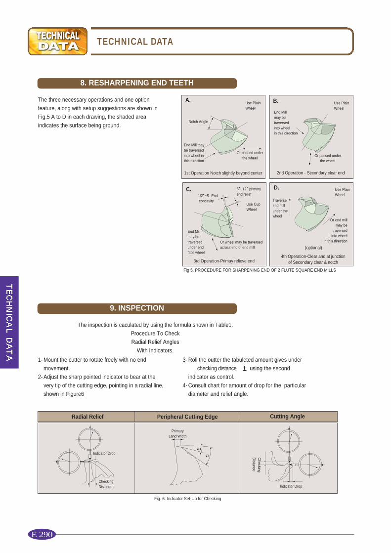
The three necessary operations and one optionfeature, along with setup suggestions are shown inFig.5 A to D in each drawing, the shaded areaindicates the surface being ground.
Fig 5. PROCEDURE FOR SHARPENING END OF 2 FLUTE SQUARE END MILLS
1- Mount the cutter to rotate freely with no endmovement.
2- Adjust the sharp pointed indicator to bear at thevery tip of the cutting edge, pointing in a radial line,shown in Figure6
3- Roll the outter the tabuleted amount gives under�� checking distance � using the secondindicator as control.
4- Consult chart for amount of drop for the particulardiameter and relief angle.
The inspection is caculated by using the formula shown in Table1.Procedure To CheckRadial Relief Angles
With Indicators.
A.
Notch Angle
1st Operation Notch slightly beyond center
End Mill may be traversed into wheel in this direction
Use PlainWheel
Use CupWheel
Or passed underthe wheel
C.1/2 ~5 Endconcavity
3rd Operation-Primay relieve end
5 ~12 primary end relief
Or wheel may be traversedacross end of end mill
Use PlainWheel
D.
4th Operation-Clear and at junction of Secondary clear & notch
Traverseend millunder thewheel
(optional)
B.
2nd Operation - Secondary clear end
End Mill may be traversed into wheel in this direction
Use PlainWheel
Or passed underthe wheel
Fig. 6. Indicator Set-Up for Checking
Radial Relief Cutting AnglePeripheral Cutting Edge
Indicator Drop
CheckingDistance Indicator Drop
CheckingDistance
PrimaryLand Width
1
2
End Mill may be traversed under end face wheel
Or end mill may be
traversedinto wheel
in this direction
8. RESHARPENING END TEETH
9. INSPECTION

E 291