Too Hot To Test
32
Too Hot To Test February 9 - 11, 2021 www.meptec.org
Transcript of Too Hot To Test

Too Hot To TestFebruary 9 - 11, 2021
www.meptec.org

February 10, 2021
Page 1Company Confidential
Jerry Tustaniwskyj
Thermal Control Challenges of High Power DUTs during Test
February 10, 2021
Director of Technology
Pick and Place Test Handler Group
February 10, 2021
Page 2Company Confidential
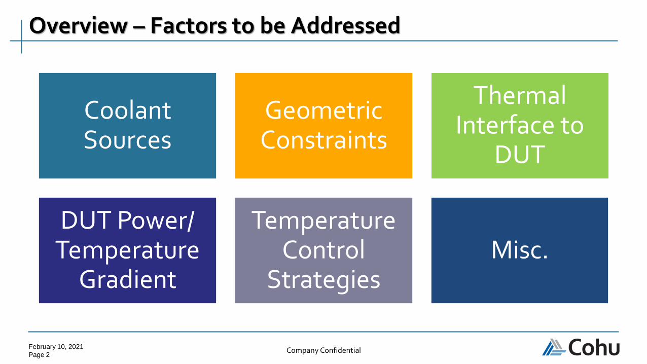
Overview – Factors to be Addressed
Coolant Sources
Geometric Constraints
Thermal Interface to
DUT
DUT Power/ Temperature
Gradient
Temperature Control
StrategiesMisc.
February 10, 2021
Page 3Company Confidential
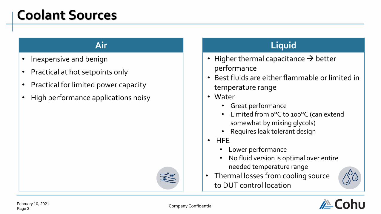
Air Liquid
• Inexpensive and benign
• Practical at hot setpoints only
• Practical for limited power capacity
• High performance applications noisy
• Higher thermal capacitance → better performance
• Best fluids are either flammable or limited in temperature range
• Water• Great performance• Limited from 0°C to 100°C (can extend
somewhat by mixing glycols)• Requires leak tolerant design
• HFE• Lower performance• No fluid version is optimal over entire
needed temperature range
• Thermal losses from cooling source to DUT control location
Coolant Sources

February 10, 2021
Page 4Company Confidential
LN2 Refrigeration Water
• Can be used to extremely
low temperatures
• Low thermal capacity,
consumption costly, and
safety concerns
• Resistance from customers
due to various reasons
• High thermal capacity
• Most effective with
evaporator at test site (not
through secondary
medium)
• Routing supply and return
lines complex
• Complexity and cost
increase significantly below
-40℃
• Multi-stage
• Oil return
• At high temperature
setpoints
• Great performance,
benign material
Phase Change

February 10, 2021
Page 5Company Confidential
Geometric Constraints - Flatness
Large Device Area
• Usually implies lower power density → easier to control
• DUT not flat• Larger thermal gaps
• Poorer control• Convex curvature is typical
• Larger thermal gap • less risk to damage bare die edges
• Sometimes can take advantage of DUT flexibility to “flatten”• Significant performance improvement• Small risk of permanent “damage” to DUT
• Many device and package styles• Requires custom thermal unit designs

February 10, 2021
Page 6Company Confidential
Geometric Constraints
Multichip Applications
• Single high-power device, multiple low power
• Contact surface on devices may not be coplanar
• High power device
• Needs tight temperature control
• All other devices
• Temperature control not as critical
• Prevent exceeding maximum temperature
• Optimize TU to control high power device
• Control low power devices with compliant TIM https://research.nvidia.com/publication/2017-06_MCM-GPU%3A-Multi-Chip-Module-GPUs
Source: NVIDIA MCM-GPU: Multi-Chip-Module GPUs for Continued Performance Scalability. June 26, 2017

February 10, 2021
Page 7Company Confidential
Geometric Constraints
Multichip Applications
• Multiple high-power devices, multiple low power
• Requires that contact surfaces for high power chips be coplanar
• If not:
• Multiple thermal units or control zones
• Technically feasible but costly
• High performance TIM
• Increasing requests to test multichip bare die
• No lid → lower thermal resistance path (a plus)
• Non coplanar → higher thermal resistance path (a minus)
https://research.nvidia.com/publication/2017-06_MCM-GPU%3A-Multi-Chip-Module-GPUs
Source: NVIDIA MCM-GPU: Multi-Chip-Module GPUs for Continued Performance Scalability. June 26, 2017
February 10, 2021
Page 8Company Confidential
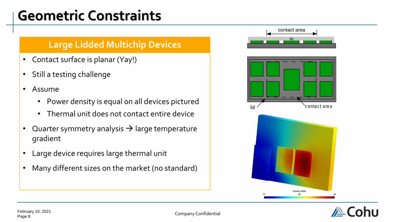
Geometric Constraints
Large Lidded Multichip Devices
• Contact surface is planar (Yay!)
• Still a testing challenge
• Assume
• Power density is equal on all devices pictured
• Thermal unit does not contact entire device
• Quarter symmetry analysis → large temperature gradient
• Large device requires large thermal unit
• Many different sizes on the market (no standard)
lid contact area
February 10, 2021
Page 9Company Confidential
Thermal Interface Materials (TIM)
❑ Requirements
• Low thermal resistance
• Highly compliant
• Reusable to many cycles
• Repeatable performance
• No residue or easily cleaned
• Easily refurbished
Thermal Interface to DUT

February 10, 2021
Page 10Company Confidential
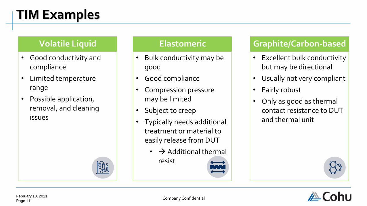
TIM Examples
Helium Malleable Metal Liquid Metal Alloy
• Inert
• Substantially better than a dry interface
• High consumption cost
• Global shortage
• Usually indium
• Good conductivity
• Subject to oxidation (unless Au)
• Creep over time
• Limited life
• Indium melts at ~150℃
• Excellent conductivity and compliance
• Oxidation
• Needs containment mechanism
• Limited temperature range
• May attack other metals (gallium)
February 10, 2021
Page 11Company Confidential
TIM Examples
Volatile Liquid Elastomeric Graphite/Carbon-based
• Good conductivity and compliance
• Limited temperature range
• Possible application, removal, and cleaning issues
• Bulk conductivity may be good
• Good compliance
• Compression pressure may be limited
• Subject to creep
• Typically needs additional treatment or material to easily release from DUT
• → Additional thermal resist
• Excellent bulk conductivity but may be directional
• Usually not very compliant
• Fairly robust
• Only as good as thermal contact resistance to DUT and thermal unit
February 10, 2021
Page 12Company Confidential
❑ In high power applications, major thermal resistance is between DUT and thermal unit
❑ Currently TIM when used is limited to a particular type of application
❑ Market for TIM used in test is small → limited supplier competition
Practical Good Performing TIM is a Critical Need!
Thermal Interface to DUT

February 10, 2021
Page 13Company Confidential
❑ Need procedure to test TIM performance in manufacturing test environment
❑ Typical method is steady state
● Well proven direct method
● Not an option if DUT thermal sensor is not available
● Applying known amount of power not trivial
● For lidded devices, lid to DUT thermal resistance variation may be greater than resolution needed for measuring the resistance of the TIM between the lid and heater
Manufacturing Test Environment
Thermal Interface to DUT

February 10, 2021
Page 14Company Confidential
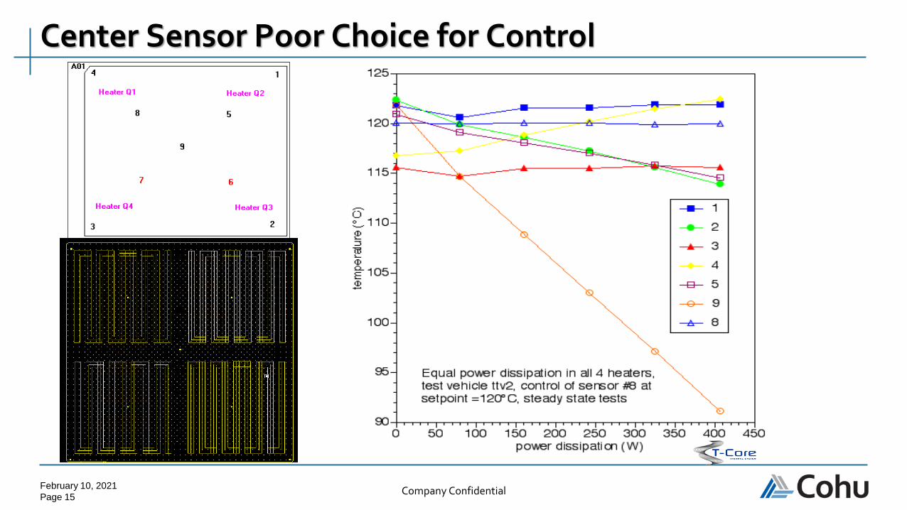
❑ For high power devices one must minimize thermal resistance from the thermal unit to the DUT, θDUT to TU
❑ When θDUT to TU approaches the DUT in plane resistance θDUT in plane or becomes less → DUT can develop significant temperature gradients
❑ Temperature gradients proportional to power dissipated
❑ Important to understand gradient
● Location of temperature sensor important
● One application controlled DUT at sensor location well
➢ Gradient caused solder balls to melt
❑ See example on next slide
● Center sensor poor choice for control
Temperature Gradient
DUT Power/ Temperature
Gradient
February 10, 2021
Page 15Company Confidential
Center Sensor Poor Choice for Control
February 10, 2021
Page 16Company Confidential
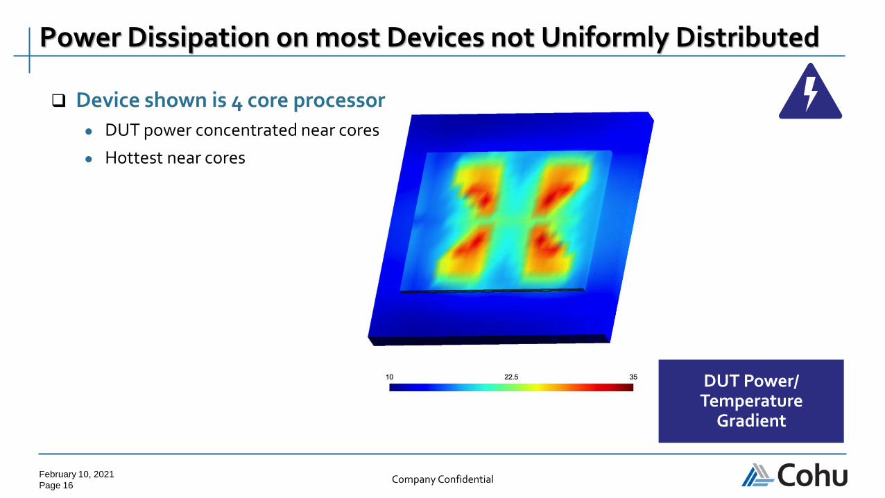
Power Dissipation on most Devices not Uniformly Distributed
DUT Power/ Temperature
Gradient
❑ Device shown is 4 core processor
● DUT power concentrated near cores
● Hottest near cores
February 10, 2021
Page 17Company Confidential
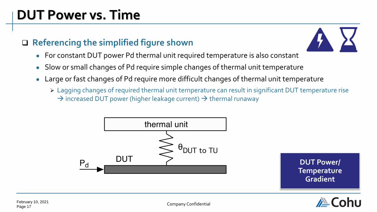
❑ Referencing the simplified figure shown
● For constant DUT power Pd thermal unit required temperature is also constant
● Slow or small changes of Pd require simple changes of thermal unit temperature
● Large or fast changes of Pd require more difficult changes of thermal unit temperature
➢ Lagging changes of required thermal unit temperature can result in significant DUT temperature rise → increased DUT power (higher leakage current) → thermal runaway
DUT Power vs. Time
DUT Power/ Temperature
Gradient

February 10, 2021
Page 18Company Confidential
❑ DUT power change magnitude more important than absolute power magnitude
● Burn-in power dissipation fairly constant → easy to control
● Functional test & SLT power varies → harder to control
● Figures below show two DUT power dissipation profiles
Importance of DUT Power Change Magnitude
0
100
200
300
400
500
600
700
0 50 100 150 200 250 300 350
po
wer
dis
sip
atio
n (
W)
time (s)
0
100
200
300
400
500
600
0 5 10 15 20 25 30 35
pw
er d
issi
pat
ion
(W
)
time (s)

February 10, 2021
Page 19Company Confidential
❑ HTF – control temperature of thermal unit
● Constant temperature of thermal unit
➢ DUT temperature = ( Pd * θDUT to TU ) + temperature of thermal unit
➢ May be acceptable if θDUT to TU is small : very good TIM!
● Change temperature of thermal unit based on anticipated power profile (open loop)
➢ Can’t use for non-constant power profiles (example: test with branching)
❑ HTF-PF - control temperature of thermal unit as a function of measured DUT power
● Called power following mode
● Fast dynamic control to get DUT temperature to desired set point temperature
● Sensitive to varying θDUT to TU
❑ Dynamic-PF - control temperature of thermal unit as a function of measured DUT power changes
● Dynamic power following
● Used with in conjunction with other control modes
Temperature Control Modes
Temperature Control Strategies
February 10, 2021
Page 20Company Confidential
❑ Control with DUT temperature sensor(s) present
● Typically diode or RTD on chip
● Theoretically more accurate and more stable
● Sensor output varies with manufacturing tolerances
➢ In-situ calibration with heater eliminates error
➢ Use saturation current cancellation technique
● Sensor location may not be optimal
➢ Non uniform power dissipation
➢ Large temperature gradients across chip
● Digital sensors beginning to appear (must be provided at fast rate)
● Common feedback from tester (not useable)
➢ Access available between subtests only
➢ No feedback without DUT power
● Strategies exist to use multiple sensor combinations
➢ Multichip modules may change sensors when powering different chips
Direct Temperature Feedback (DTF)
Temperature Control Strategies

February 10, 2021
Page 21Company Confidential
❑ Liquid cooled application, DUT temperature Td vs. DUT power Pd
Direct Temperature Feedback (DTF)
Temperature Control Strategies
February 10, 2021
Page 22Company Confidential
❑ Some devices do not allow device or power feedback
● Power feedback may only be partial
❑ Calculate DUT Temperature based on thermal head dynamics only
● Multiple sensors in thermal unit
❑ Not as robust as PF
❑ Requires low θDUT to TU → (excellent TIM!)
● Cannot extrapolate too far
❑ Contains dynamic term
Extrapolated Temperature Feedback (ETF)
Temperature Control Strategies
February 10, 2021
Page 23Company Confidential
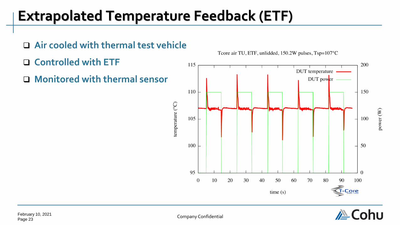
Extrapolated Temperature Feedback (ETF)
❑ Air cooled with thermal test vehicle
❑ Controlled with ETF
❑ Monitored with thermal sensor

February 10, 2021
Page 24Company Confidential
❑ Fortunately, power dissipation is typically much lower at cold than hot
❑ Larger difference between setpoint and cold source temperatures allows high heat transfer rates
❑ -40℃ often considered a practical limit
❑ As cold source temperatures decrease, complexity and costs go up exponentially
● Multi-stage compressor
● LN2
● Condensation control
❑ Secondary paths to ambient
● Helps control at hot
● Adds additional burden at cold
Much Easier Temperature Control at Hot Setpoints vs Cold

February 10, 2021
Page 25Company Confidential
❑ Absolute power not the best measure of temperature control difficulty
● Dominant factors:
➢ DUT power dissipation density
➢ Magnitude of DUT power dissipation changes during test
➢ Test temperature setpoint
➢ DUT package resistance
➢ Device geometry
❑ Application requirement vary greatly
❑ Initial requirements for application often erroneous
● Sometimes to stringent and sometimes too lax
❑ New temperature control candidates (such mobile or automotive applications)
● Newest devices dissipate significant amount of power
● New territory for these test engineers
Other comments

February 10, 2021
Page 26Company Confidential
DANKE
GRAZIE
MAHALODANKEJE
XIE XIE
EF
HA
RIS
TO
FA
LE
MIN
DE
RIT
PALDIES
KIITOS
MERCI
SPASIBO
HVALA
DA
NK
U
Gamsahabnida
NG
IYA
BO
NG
A
OBRIGADO
GR
AT
IAS
TIB
I
TERIMA KASIH
AS
AN
TE
SH
UK
RA
N
TO
DA
DO JEH
DEKUJI
SHUKRIYA
Khob-kunKöszönöm
Go raibh maith agaibh Cảm ơn
Tusen takk
Dhanyavaad
Grazzi

Thank you sponsors!

A global leader in the ATE industry with a WW installed base of over 30,000 systems
Our nanotechnology products support leading-edge
semiconductor processes at the 1Xnm node
Our diverse workforceincludes 5,500 employees
from 50 countries
Eco-friendly policies emphasize reduction of
our carbon footprint
2018 Global Technology Leaderby Thomson Reuters
60+Innovating in the measurement arena
for 60+ years A VLSIresearch 10 BEST supplier
for 32 consecutive years


COPYRIGHT NOTICEThis presentation in this publication was presented at Too Hot to Test (February 9-11, 2021). The content reflects the opinion of the author(s) and their respective companies. The inclusion of presentations in this publication does not constitute an endorsement by MEPTEC or the sponsors.
There is no copyright protection claimed by this publication. However, each presentation is the work of the authors and their respective companies and may contain copyrighted material. As such, it is strongly encouraged that any use reflect proper acknowledgement to the appropriate source. Any questions regarding the use of any materials presented should be directed to the author(s) or their companies.
www.meptec.org