Tomography - CIME | EPFL · PDF fileTEM Tilt-Series Tomography in Life Science ... tomo...
19
MSE-635 STEM-Tomography 2014 Tomography Introduction to Tomography TEM Tilt-Series Tomography in Life Science STEM Tomography in Materials Science MSE-635 STEM-Tomography 2014 2 Introduction to Tomography Introduction to Tomography • Tomography is imaging by sections or sectioning. A device used in tomography is called a tomograph, while the image produced is a tomogram. • The method is used in medicine, archaeology, biology, geophysics, oceanography, materials science, astrophysics and other sciences. • In most cases it is based on the mathematical procedure called tomographic reconstruction. • The word "tomography" is derived from the Greek tomos (slice) and graphein (to write). Wickipedia
Transcript of Tomography - CIME | EPFL · PDF fileTEM Tilt-Series Tomography in Life Science ... tomo...

MSE-635 STEM-Tomography 2014
Tomography
Introduction to Tomography
TEM Tilt-Series Tomography in Life Science
STEM Tomography in Materials Science
MSE-635 STEM-Tomography 2014 2
Introduction to TomographyIntroduction to Tomography
• Tomography is imaging by sections or sectioning. A device used in tomography is called a tomograph, while the image produced is a tomogram.
• The method is used in medicine, archaeology, biology, geophysics, oceanography, materials science, astrophysics and other sciences.
• In most cases it is based on the mathematical procedure called tomographic reconstruction.
• The word "tomography" is derived from the Greektomos (slice) and graphein (to write).
Wickipedia

MSE-635 STEM-Tomography 2014 3
Introduction to TomographyIntroduction to Tomography
• Tomography is a method in which a 3-D structure is reconstructed from a series of 2-D projections (images) acquired at successive tilts (Radon 1917).
• First developed for use in medical imaging (1963, Nobel Prize for Medicine in 1979) using X-rays, ultrasound and magnetic resonance (e.g. ‘cat-scans’)..
• Found further application in geology, astronomy, materials science, etc…
P. Midgley, tomo workshop in Berlin
MSE-635 STEM-Tomography 2014 4
Introduction to TomographyIntroduction to Tomography
Recording
• Series of 2D images• Destructive: serial
sectioning, FIB• Non-destructive:
X-rays, TEM
Reconstruction and « viewing »
• Registration (alignment of images)
• Back-projection, reconstruct(tilt-series)
• Tomogram• Segmentation (image
processing), extraction of the desired information

MSE-635 STEM-Tomography 2014 5
3D imaging in medicine3D imaging in medicine
• Non-invasive methods are preferred!
• The disadvantage of conventional X-radiographs is its inability to discriminate between organs of close absorptivity or overlapping organs in the viewing direction.
• X-ray computed tomography overcomes that limitation:
• X-radiographs are made in many different directions and combined mathematically to to reconstruct cross-sectional maps.
• reconstruction tomography or computer assisted tomography.
MSE-635 STEM-Tomography 2014 6
TomographTomograph

MSE-635 STEM-Tomography 2014 7
Radon 1917Radon 1917
Ber. Sächs. Akad. Wiss. Leipzig, Math. Phys. Kl. 69, 262 (1917)
English translation in: Deans, S.R. (1983) The Radon transform and its applications. John Wiley & Sons, NY)
MSE-635 STEM-Tomography 2014 8
Radon TransformRadon Transform
MSE-635 STEM-Tomography 2014 9
Radon TransformRadon Transform
MSE-635 STEM-Tomography 2014 10
Radon TransformRadon Transform
MSE-635 STEM-Tomography 2014 11
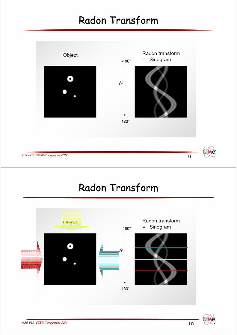
Back projectionBack projection
Projectionrecording
Back projectionreconstructing
MSE-635 STEM-Tomography 2014 12
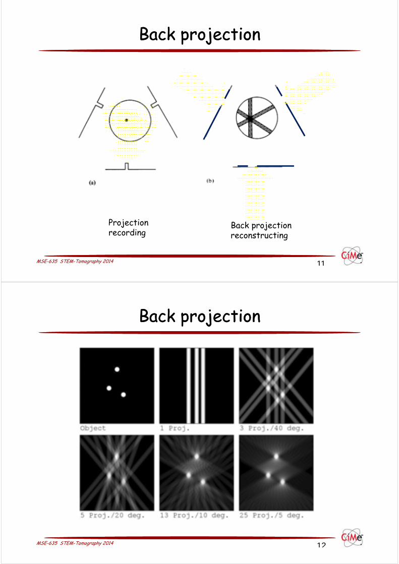
Back projectionBack projection
MSE-635 STEM-Tomography 2014 13
back projectionback projection
MSE-635 STEM-Tomography 2014 14
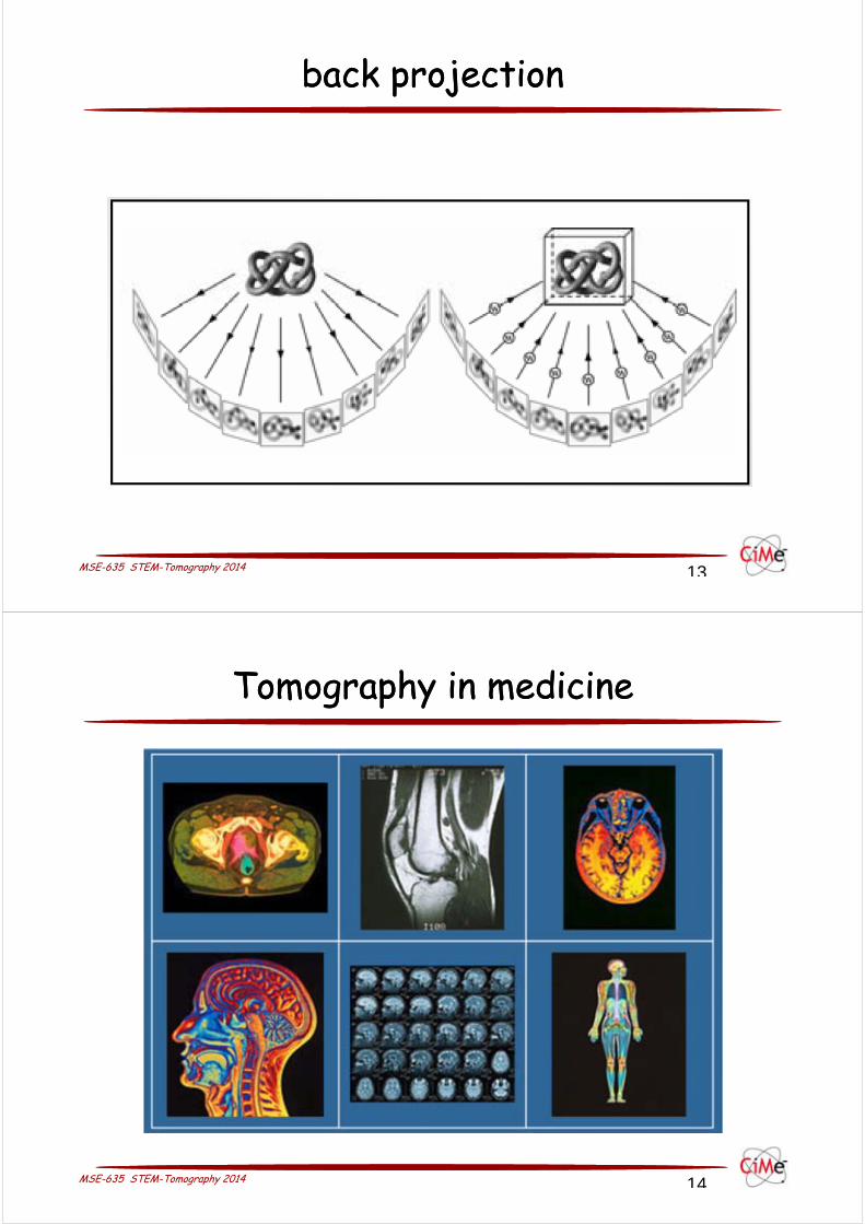
Tomography in medicineTomography in medicine

MSE-635 STEM-Tomography 2014 15
3D imaging in materials science3D imaging in materials science
360degree X-ray tomographyMilan FelberbaumSTI-IMX-LSMX
Cylinder of an Al-Cu Alloy
MSE-635 STEM-Tomography 2014 16
3D imaging in materials science3D imaging in materials science
Tomogram

MSE-635 STEM-Tomography 2014 17
3D imaging in materials science3D imaging in materials science
Reconstructed pore
MSE-635 STEM-Tomography 2014 18
Tomography with electronsTomography with electrons
Element(specific weight)
4-Be1.84 g/cm3
13-Al2.7 g/cm3
29-Cu8.93 g/cm3
82-Pb11.3 g/cm3
X-raysCu-Kα λ=1.54 ÅMo-Kα λ=0.71 Å
16 mm83 mm
0.35 mm 3.3 mm
0.10 mm0.10 mm
0.017 mm 0.034 mm
Neutrons λ≈1.08 Å 89 m 6 m 0.26 m 14 m
Électronsλ=0.037 Å à 100 kV λ=0.020 Å à 300 kV
39 µm 42 µm~330 µm
11 µm 0.6 µm
Stopping range for electrons (99% absorbed)

MSE-635 STEM-Tomography 2014 19
Bio-EM, TomographyBio-EM, Tomography
MSE-635 STEM-Tomography 2014 20
Tilt series, -60 … +60 degree tiltTilt series, -60 … +60 degree tilt

MSE-635 STEM-Tomography 2014 21
TomogramTomogram
MSE-635 STEM-Tomography 2014 22
Tomo workflowTomo workflow

MSE-635 STEM-Tomography 2014 23
resolutionresolution
MSE-635 STEM-Tomography 2014 24
geometrical limit, the missing wedgegeometrical limit, the missing wedge

MSE-635 STEM-Tomography 2014 25
Missing wedgeMissing wedge
MSE-635 STEM-Tomography 2014 26
Weighted back projection WBPWeighted back projection WBP
Lim
ited
num
ber
of p
roje
ctio
ns
Lim
ited
tilt

MSE-635 STEM-Tomography 2014 27
• projection requirement: monotonically varying function of a physical property: mass-thickness dominant in biological samples !
Si-Ge multiple quantum well structure
projection requirementprojection requirement
MSE-635 STEM-Tomography 2014 28
Tomography in Electron MicroscopyTomography in Electron Microscopy
Fro
m P
. Mid
gley

MSE-635 STEM-Tomography 2014 29
Tomography with HAADF (z-contrast)Tomography with HAADF (z-contrast)
nanoparticle bimetallic catalystssupported on mesoporous silica
Dogan Ozkaya,Paul Midgley;Catalysis Letters 60 (1999) 113–120
STEM HAADF: heterogeneous catalystcomposed of Pd6Ru6 nanoparticles (~ 1 nm)on mesoporous silica support withmesopores of ~ 3 nm diameter.
Pd6Ru6 nanoparticlesanchored to the wall
of mesopore
MSE-635 STEM-Tomography 2014
Emad Oveisi (CIME): STEM DF Tomography of Dislocations
STEM‐ADF tilt series (‐35/+35°) of Mo pillar with [155] compression axis
Mo Pillar
[155]
[211] [‐111]
‐100
011
01‐1
[‐10 1 1]
‐111
0‐11211
01‐1

MSE-635 STEM-Tomography 2014
High tilt range required to acquire a tilt series(up to +/‐70 degree)Increasing the effective thickness with tilt (2 times thicker at 60 degree!)No uniform focus: Dynamic focus package is required
Misalignment between the tilt axis and diffraction axis; May change the excitation error during tilt series acquisition and results in inconsistent images
Changes of diffraction contrast during tilting; e.g. close to zone axes
3D reconstruction is not always straightforward; e.g. missing wedge effect, complications due to surface artifacts, etc.
Problems Associated with Tomography
MSE-635 STEM-Tomography 2014
3D Reconstruction
Developing an algorithm for 3D Reconstruction of Dislocations from TEM images
A collaboration with Computer Vision Laboratory at EPFL
Algorithm for 3D observation of Dislocations
Dr. A. LetouzeyE. Oveisi
Prof. C. Hebert Prof. P. Fua
CVLAB
Dr. G. Lucas
Dr. M. Cantoni
Microscopy

MSE-635 STEM-Tomography 2014
Algorithm for 3D observation of Dislocations
α=8°ß=1.1°
α=9°ß=1.2°
α=10°ß=1.2°
α=11°ß=1.3°
Using state of the art curvilinear structures detectionalgorithm, the dislocation segments are extracted semi‐automatically in ADF‐STEM images.
These 2D representations of dislocations are thenautomatically matched between images.
3D estimation of the dislocation structure is performedfrom these segments by taking into account the cameracalibration and tilt angle for each image.
Benmansour, F. et al., “Tubular Geodesics using Oriented Flux: An ITK Implementation”, Insight Journal (2013).
Türetken, E. et al., “Semi‐Automated Reconstruction of Curvilinear Structures in Noisy 2D images and 3D image stacks”, EPFL Technical Report (2013).
MSE-635 STEM-Tomography 2014
Algorithm for 3D observation of Dislocations
3D visualization of dislocations

MSE-635 STEM-Tomography 2014
Second example: Dislocations in GaN
3D reconstruction using SIRT algorithm
STEM‐ADF tilt series (‐25/+25°) of GaN with [1‐100] foil direction
Reconstruction using SIRT algorithm
MSE-635 STEM-Tomography 2014
Quentin Jeangros, SOFCQuentin Jeangros, SOFC

MSE-635 STEM-Tomography 2014