Tomographic velocity analysis and wave-equation depth...
13
Tomographic velocity analysis and wave-equation depth migration in an overthrust terrain: A case study from the Tuha Basin, China Bin Lyu 1 , Qin Su 2 , and Kurt J. Marfurt 1 Abstract Although the structures associated with overthrust terrains form important targets in many basins, accurately imaging remains challenging. Steep dips and strong lateral velocity variations associated with these complex structures require prestack depth migration instead of simpler time migration. The associated rough topogra- phy, coupled with older, more indurated, and thus high-velocity rocks near or outcropping at the surface often lead to seismic data that suffer from severe statics problems, strong head waves, and backscattered energy from the shallow section, giving rise to a low signal-to-noise ratio that increases the difficulties in building an accurate velocity model for subsequent depth migration. We applied a multidomain cascaded noise attenuation workflow to suppress much of the linear noise. Strong lateral velocity variations occur not only at depth but near the surface as well, distorting the reflections and degrading all deeper images. Conventional elevation corrections followed by refraction statics methods fail in these areas due to poor data quality and the absence of a con- tinuous refracting surface. Although a seismically derived tomographic solution provides an improved image, constraining the solution to the near-surface depth-domain interval velocities measured along the surface out- crop data provides further improvement. Although a one-way wave-equation migration algorithm accounts for the strong lateral velocity variations and complicated structures at depth, modifying the algorithm to account for lateral variation in illumination caused by the irregular topography significantly improves the image, preserving the subsurface amplitude variations. We believe that our step-by-step workflow of addressing the data quality, velocity model building, and seismic imaging developed for the Tuha Basin of China can be applied to other overthrust plays in other parts of the world. Introduction Although the structures associated with overthrust terrains form important targets in many basins, accurate seismic imaging remains challenging. There are often serious lateral velocity variations in overthrust belts, which lead to ray bending, resulting in time-migrated seismic images that are poorly focused images and mis- positioned reflectors and diffracting edges. Depth migra- tion is required to image complex overthrust structures with strong lateral velocity variations. Unfortunately, the imaging problems are not confined to the deeper struc- tures. Rough topography and outcropped older, high- velocity rocks in overthrust belts (Alfonso and Guevara, 2004) often lead to seismic data contaminated by head- waves and coherent backscattered noise resulting in a low signal-to-noise ratio (S/N) and serious statics prob- lems, which complicate the velocity model building proc- ess critical to accurate depth migration. Alfonso (2001) identifies three major challenges in overthrust imaging: topography and its correction, the lower S/N associated with structure outcropping on the surface, and complex subsurface structures. Other authors have addressed the rough topography and change in elevation encountered in overthrust belt imaging. Reshef (1991), Gray and Marfurt (1995), and Shragge (2005) find that depth migration directly from topography provided more accurate images compared with those computed from a flat datum after static cor- rections. However, the velocity model building difficulty remains, with a key challenge being how to integrate the near-surface velocity model computed from refracted waves with the deeper velocity model computed from reflected waves. Static correction plus migration from a floating datum provides a practical, but only partial, solution to this difficult problem. Yilmaz (2001) summa- rizes several static correction solutions, including field statics, refraction statics (Schneider and Kuo, 1985; Ta- ner et al., 1998), and tomostatics (Zhu et al., 1992, 1998; Bell et al., 1994; Osypov, 1998). Accurate refraction stat- ics computation requires continuous refractors and good 1 The University of Oklahoma, ConocoPhillips School of Geology and Geophysics, Norman, Oklahoma, USA. E-mail: [email protected]; kmarfurt@ ou.edu. 2 Petrochina Research Institute of Petroleum Exploration & Development-Northwest, Lanzhou, Gansu, China. E-mail: [email protected]. Manuscript received by the Editor 13 March 2017; revised manuscript received 19 July 2017; published ahead of production 19 September 2017; published online 14 November 2017. This paper appears in Interpretation, Vol. 6, No. 1 (February 2018); p. T1–T13, 13 FIGS. http://dx.doi.org/10.1190/INT-2017-0053.1. © 2018 Society of Exploration Geophysicists and American Association of Petroleum Geologists. All rights reserved. t Technical papers Interpretation / February 2018 T1 Interpretation / February 2018 T1 Downloaded 02/12/18 to 129.15.66.178. Redistribution subject to SEG license or copyright; see Terms of Use at http://library.seg.org/
Transcript of Tomographic velocity analysis and wave-equation depth...

Tomographic velocity analysis and wave-equation depth migrationin an overthrust terrain: A case study from the Tuha Basin, China
Bin Lyu1, Qin Su2, and Kurt J. Marfurt1
Abstract
Although the structures associated with overthrust terrains form important targets in many basins, accuratelyimaging remains challenging. Steep dips and strong lateral velocity variations associated with these complexstructures require prestack depth migration instead of simpler time migration. The associated rough topogra-phy, coupled with older, more indurated, and thus high-velocity rocks near or outcropping at the surface oftenlead to seismic data that suffer from severe statics problems, strong head waves, and backscattered energy fromthe shallow section, giving rise to a low signal-to-noise ratio that increases the difficulties in building an accuratevelocity model for subsequent depth migration. We applied a multidomain cascaded noise attenuation workflowto suppress much of the linear noise. Strong lateral velocity variations occur not only at depth but near thesurface as well, distorting the reflections and degrading all deeper images. Conventional elevation correctionsfollowed by refraction statics methods fail in these areas due to poor data quality and the absence of a con-tinuous refracting surface. Although a seismically derived tomographic solution provides an improved image,constraining the solution to the near-surface depth-domain interval velocities measured along the surface out-crop data provides further improvement. Although a one-way wave-equation migration algorithm accounts forthe strong lateral velocity variations and complicated structures at depth, modifying the algorithm to account forlateral variation in illumination caused by the irregular topography significantly improves the image, preservingthe subsurface amplitude variations. We believe that our step-by-step workflow of addressing the data quality,velocity model building, and seismic imaging developed for the Tuha Basin of China can be applied to otheroverthrust plays in other parts of the world.
IntroductionAlthough the structures associated with overthrust
terrains form important targets in many basins, accurateseismic imaging remains challenging. There are oftenserious lateral velocity variations in overthrust belts,which lead to ray bending, resulting in time-migratedseismic images that are poorly focused images and mis-positioned reflectors and diffracting edges. Depth migra-tion is required to image complex overthrust structureswith strong lateral velocity variations. Unfortunately, theimaging problems are not confined to the deeper struc-tures. Rough topography and outcropped older, high-velocity rocks in overthrust belts (Alfonso and Guevara,2004) often lead to seismic data contaminated by head-waves and coherent backscattered noise resulting in alow signal-to-noise ratio (S/N) and serious statics prob-lems, which complicate the velocitymodel building proc-ess critical to accurate depth migration. Alfonso (2001)identifies three major challenges in overthrust imaging:topography and its correction, the lower S/N associated
with structure outcropping on the surface, and complexsubsurface structures.
Other authors have addressed the rough topographyand change in elevation encountered in overthrust beltimaging. Reshef (1991), Gray and Marfurt (1995), andShragge (2005) find that depth migration directly fromtopography provided more accurate images comparedwith those computed from a flat datum after static cor-rections. However, the velocity model building difficultyremains, with a key challenge being how to integrate thenear-surface velocity model computed from refractedwaves with the deeper velocity model computed fromreflected waves. Static correction plus migration froma floating datum provides a practical, but only partial,solution to this difficult problem. Yilmaz (2001) summa-rizes several static correction solutions, including fieldstatics, refraction statics (Schneider and Kuo, 1985; Ta-ner et al., 1998), and tomostatics (Zhu et al., 1992, 1998;Bell et al., 1994; Osypov, 1998). Accurate refraction stat-ics computation requires continuous refractors and good
1The University of Oklahoma, ConocoPhillips School of Geology and Geophysics, Norman, Oklahoma, USA. E-mail: [email protected]; [email protected].
2Petrochina Research Institute of Petroleum Exploration & Development-Northwest, Lanzhou, Gansu, China. E-mail: [email protected] received by the Editor 13 March 2017; revised manuscript received 19 July 2017; published ahead of production 19 September 2017;
published online 14 November 2017. This paper appears in Interpretation, Vol. 6, No. 1 (February 2018); p. T1–T13, 13 FIGS.http://dx.doi.org/10.1190/INT-2017-0053.1. © 2018 Society of Exploration Geophysicists and American Association of Petroleum Geologists. All rights reserved.
t
Technical papers
Interpretation / February 2018 T1Interpretation / February 2018 T1
Dow
nloa
ded
02/1
2/18
to 1
29.1
5.66
.178
. Red
istr
ibut
ion
subj
ect t
o SE
G li
cens
e or
cop
yrig
ht; s
ee T
erm
s of
Use
at h
ttp://
libra
ry.s
eg.o
rg/
data, but it often fails when the data are poor or when therefracting horizons are discontinuous. Overthrust beltsexhibit different types of topography, with a weatheringzone occurring at lower elevations and outcrops athigher elevations, with no continuous refractor runningacross the entire survey. Such a near-surface problemcannot be solved well with only one static correctionmethod.
Wang et al. (2012) identify several types of noisecommon to overthrust belts. Older and more induratedrocks outcrops give rise to high-amplitude headwaves,backscattered energy, and other linear noise, whichoverprints the reflections of interest. Such noise makesvelocity model building much more difficult becausethe linear noise masks the reflections in common-imagegathers and gives rise to semblance anomalies that mayintroduce incorrect velocity picks.
Ritchie et al. (2005) note the significant structural dis-tortion due to severe thrusting or compression in over-thrust belts. The structures in these areas are often verycomplicated and give rise to serious lateral velocity var-iations. Compared with lower cost Kirchhoff migrationand higher cost reverse time migration (RTM), one-waywave-equation migration (Claerbout, 1971; Stoffa et al.,1990; Ristow and Ruhl, 1994) provides a practical solu-
tion to overthrust imaging, providing the multipathingbenefits of a wave-equation method but at a reduced costand somewhat reduced sensitivity to velocity errors thanRTM. Although Jiao et al. (2004) apply this technique tosynthetics and Shragge (2005) to field data, one-waywave-equation solutions face challenges in accuratelyaccounting for topography and high velocities near thesurface overlying slower velocities at depth, thereby fil-tering out shorter wavelength components representingsteeper dips to make the algorithm stable.
Constructing an accurate velocity model is a key toaccurate depth imaging in an overthrust belt. For theareas with relatively simple structures and high-S/Ndata, layer-based coherency inversion (Yilmaz, 2001),or simple conversion of stacking velocities (Dix, 1955)can provide an initial interval velocity model. After con-structing the first pass of (approximately flattened) mi-grated gathers, one can use tomography to update thevelocity model (Etgen, 1988; Stork, 1992). However,these methods often fail where rocks outcrop at the sur-face and where the S/N is low. In this case, geologic in-formation needs to be incorporated as well to build amore accurate depth-domain velocity model.
We begin our paper by building a synthetic waveequation model to better evaluate the quality of the seis-mic images from the prestack time- and depth-migrationmethods. We then introduce the depth-imaging work-flow to be used in the overthrust belt. Next, we indicatethe benefit of tomography in addressing statics issuesassociated with near-surface or outcrop high-velocityrocks. We address the S/N through a multidomain noiseattenuation workflow. We then apply an amplitude-pre-served one-way depthmigration that compensates for lat-eral variation in wave illumination. Finally, we integrateadditional velocity information from geologic outcropsto constrain our depth-domain velocity model, therebyimproving our images. We conclude with summary com-ments and recommendations for further analysis.
Time imaging or depth imaging?Although laterally variable from image point to im-
age point, the velocity model for time migration at agiven image point is either constant or a simple gradientof the form v ¼ v0 þ kz, such that there is no ray kink-ing. In contrast, the velocity model for depth migrationattempts to approximate the true layer-by-layer intervalvelocities with ray bending and kinking at each abruptchange in the velocity-depth model (Gray et al., 2001).In time migration, the imaging velocity model oftenbegins with the root-mean-square (rms) velocity com-puted from unmigrated CMP gathers, which is thenscaled to obtain the best focusing at every output loca-tion (Gray et al., 2001). Because there are no lateralvelocity variations to focus the energy at a given imagepoint, there is no need for explicit ray tracing, such thattime migration is much faster than depth migration. Ifthere are significant lateral velocity variations that giverise to ray bending, time migration not only laterally mis-positions a given dipping seismic event, but it may also
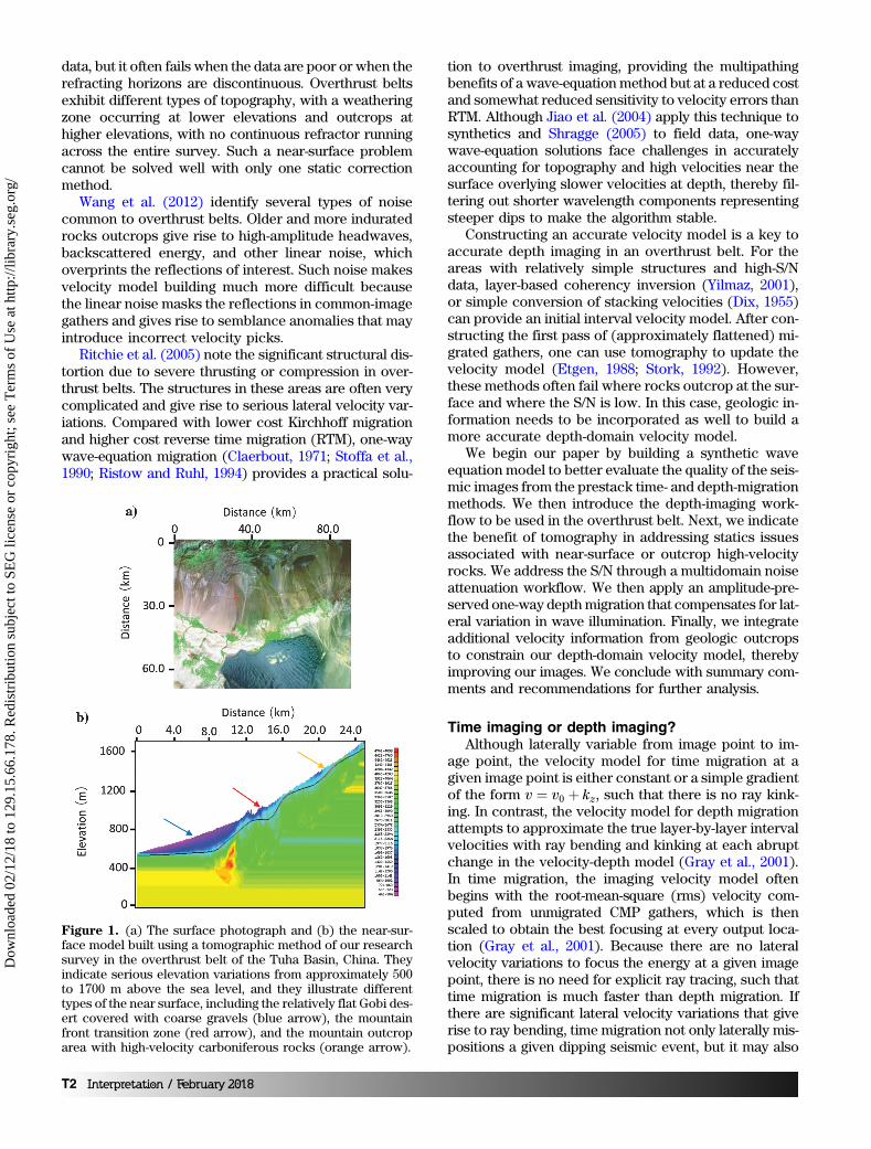
Figure 1. (a) The surface photograph and (b) the near-sur-face model built using a tomographic method of our researchsurvey in the overthrust belt of the Tuha Basin, China. Theyindicate serious elevation variations from approximately 500to 1700 m above the sea level, and they illustrate differenttypes of the near surface, including the relatively flat Gobi des-ert covered with coarse gravels (blue arrow), the mountainfront transition zone (red arrow), and the mountain outcroparea with high-velocity carboniferous rocks (orange arrow).
T2 Interpretation / February 2018
Dow
nloa
ded
02/1
2/18
to 1
29.1
5.66
.178
. Red
istr
ibut
ion
subj
ect t
o SE
G li
cens
e or
cop
yrig
ht; s
ee T
erm
s of
Use
at h
ttp://
libra
ry.s
eg.o
rg/

separate or overlap adjoining parts of what should be acontinuous reflector.
The velocity model used in depth migration is asmoothed representation of the true interval velocity,where for Kirchhoff migration, the smoothness is on theorder of a wavelength (Gray et al., 2001), but it can beless for the one-way wave equation and RTM algo-rithms. All three of these implementations (ray-based,one-way wave-equation, or hyperbolic two-way waveequation) algorithms accurately bend the rays at eachlocation in the subsurface where the velocity changes,such that depth migration can image complicated sub-surface structures much more accurately than time mi-gration can.
In our study, we perform the numerical tests on aland survey with overthrust structures of the Tuha Ba-sin. The survey exhibits complicated subsurface struc-tures and rugged topography. Figure 1a shows thesurface photograph that covers our survey, which indi-cates very complex near-surface conditions. Figure 1bshows the near-surface model built using a tomographicmethod, which indicates serious elevation variationsfrom approximately 500 to 1700 m above sea level.Figure 1a and 1b also illustrates different types of thenear surface, including the relatively flat Gobi desertcovered with coarse gravels (blue arrow), the mountainfront transition zone (red arrow), and themountain outcrop areawith high-velocitycarboniferous rocks (orange arrow).
Although some pitfalls of time migra-tion, such as velocity pull up/push down(e.g., Fagin, 1996) are well-known to in-terpreters working on overthrust terrains,we reveal these phenomena by construct-ing the model shown in Figure 2b basedon the depth-domain structural inter-pretation (Figure 2a) of a typical line inthe overthrust belt shown in Figure 1.There are a shallow overthrust structureand some underlying faults in the model.We then generate a suite of common-shot synthetics using a 2D finite-differ-ence scalar wave-equation algorithm. Thetime-processing steps prior to migrationare similar to those applied to the fielddata. Figure 2c and 2d shows the result-ing prestack time- and depth-migrated im-ages. Note the improved fidelity of thedepth-migrated image compared with thetrue model. Faults are accurately imagedto their correct location in depth migra-tion, but they are distorted and misposi-tioned by time migration. There arestrong fault shadow effects on the deep-est two reflectors (yellow arrows) in theprestack time-migration image, whichare caused by the rapidly varying lateralvelocity contrast across the dippingfaults. These reflections are nonhyper-
bolic around the faults, resulting in weak time-migratedimages. It is difficult to image these dipping fault zoneswith prestack timemigration (Figure 2c), due to its inabil-ity to handle lateral velocity variations. The fault-planereflection is also mispositioned with prestack time migra-tion (blue arrows). In contrast, prestack depth-migrationimages these fault zones much better (Figure 2d). Thereare fewer migration artifacts in depth imaging, with thepull-up artifacts removed. Multiples are more coherent,but they are easier to identify as being multiples on theprestack time-migrated volume, indicated by the red ar-rows in Figure 2c. On the depth-migrated data, the multi-ples are weaker, but they are no longer periodic, and theymay be misidentified as primaries on the prestack depth-migrated data volume (red arrow in Figure 2d).
The primary processing steps of the workflow areshown in Figure 3. Other steps, such as geometry def-inition, first-break picking, muting, and velocity pickingalso affect the imaging quality. There are four key stepsfor depth imaging in the overthrust belt: static correc-tions, noise attenuation, the prestack depth migrationalgorithm, and depth-domain velocity model building.Each will be discussed in detail in the following sub-sections.
Figure 2. A synthetic model built from the image of the Tuha Basin to quantifyany limits in imaging the overthrust structures. (a) Depth-domain structural in-terpretation of a typical line of our research survey. (b) Velocity-depth modelused to generate acoustic wave equation synthetic shot gathers using a finite-difference algorithm. Resulting images from (c) prestack time migration and(d) prestack depth migration. Note the strong fault shadow effects on the deep-est two reflectors (yellow arrows) on the prestack time migration. Prestackdepth migration could image these fault zones much better. The fault-plane re-flection is also mispositioned with prestack time migration (blue arrows). Thereare fewer migration artifacts in depth imaging, and the pull-up pitfall is also re-moved in depth imaging. In contrast, the multiples are more coherent, but theyare easier to identify as being multiples on the prestack time-migrated volume.Although the multiples are weaker, they may be misidentified as being structureson the prestack depth-migrated data volume (red arrows).
Interpretation / February 2018 T3
Dow
nloa
ded
02/1
2/18
to 1
29.1
5.66
.178
. Red
istr
ibut
ion
subj
ect t
o SE
G li
cens
e or
cop
yrig
ht; s
ee T
erm
s of
Use
at h
ttp://
libra
ry.s
eg.o
rg/

Computing the near-surface velocity modelProperly accounting for elevation and weathering
zone effects is critical for land processing (Yilmaz, 2001),and it is more challenging in areas with rough topogra-phy, such as in overthrust terrains. The Tuha Basinexpresses variable topography, including flat plains anddesert, the mountain front, and the mountains them-selves. In most land surveys, the seismic data are re-corded by geophones deployed on the surface of alow-velocity weathering zone. Energy impinging the baseof the weathering zone at shallow angles is refracted to-ward the normal, which for relatively flat topography andweathering zones, toward the vertical, such that theweathering zone correction can be approximated by avertical (static) shift of the seismic trace. In the case ofrough topography, the surface and the base of the weath-ering zone may not be flat. In some cases, such as in theTuha Basin overthrust belt, there is no weathering zoneat all, but rather the folded rocks outcrop at the surface.
In this case, there is no bending of raypaths toward thevertical because they approach the surface. Taner et al.(1974) show that correcting these measurements to aflat datum requires a “dynamic” rather than a “static” cor-rection, whereby each reflection event needs to be cor-rected to the data by its angle of incidence back to thedatum along the raypath, rather than vertically. Reshef(1991), Gray and Marfurt (1995), and Shragge (2005)show that migration directly from topography implicitlycomputes such a dynamic correction, providing signifi-cantly more accurate images than the migration of datapreviously corrected to a flat datum using static cor-rections.
Although migration from topography has been avail-able for decades, estimating an accurate velocity inthe low-fold shallow section is still difficult in the TuhaBasin survey, refraction statics velocity analysis basedon smooth, continuous refractors fails. Furthermore,the velocity field estimated from shallow refractionsand that estimated from deeper reflections have differ-ent scales, making their integration into a unified veloc-ity-depth model difficult.
Rough topography can be considered to have low-and high-frequency components. The floating datum rep-resents the low-frequency component, which could alsobe considered to be a smoothed version of topography.For the Tuha Basin overthrust data, we use a two-stepcorrection: First, we correct the high-frequency compo-nent to a floating data, followed by migration from thefloating datum. By this, the inaccurate vertical correctionto a flat datum is minimized, whereas the data can beregularized to a grid, in which the one-way wave-equa-tion solutions can operate.
Yilmaz (2001) summarizes several different staticcorrection methods to correct the high-frequency com-ponent of topography, including field statics, refractionstatics (Schneider and Kuo, 1985; Taner et al., 1998),and tomostatics (Zhu et al., 1992; Bell et al., 1994; Osy-pov, 1998). Refraction statics works well for continuousrefractors and good-quality data, but it may fail in thepresence of discontinuous refractors and poor-qual-ity data.
The Tuha Basin overthrust belt is represented by sig-nificant lateral variations in the near-surface structures.In our research area, the near-surface changes from theGobi Desert through a mountain front transition zone,followed by the mountain outcrop area (Figure 1b). TheGobi Desert is relatively flat with small elevation varia-tions. In the mountain front transition zone, the eleva-tion variations become larger, but there is still a stablerefraction layer. The mountain outcrop area exhibitsserious lateral variations, and there are no stable refrac-tion layers.
Given the heterogeneity, no single static correctiontechnique works for the entire line. We illustrate our hy-brid static correction workflow using a representativeline drawn from the survey shown in Figure 4. Three dif-ferent static correction methods, including field statics,refraction statics, and tomostatics, are used for numeri-
Figure 3. The seismic processing workflow in the overthrustbelt indicate the four key steps for seismic imaging in the over-thrust belt, including statics correction, noise attenuation,prestack depth-migration algorithm, and depth-domain veloc-ity model building.
T4 Interpretation / February 2018
Dow
nloa
ded
02/1
2/18
to 1
29.1
5.66
.178
. Red
istr
ibut
ion
subj
ect t
o SE
G li
cens
e or
cop
yrig
ht; s
ee T
erm
s of
Use
at h
ttp://
libra
ry.s
eg.o
rg/

cal tests. Figure 4a, 4d, and 4g shows the imaging resultsin the Gobi desert area after static correction with thesethree different methods. In this area, the topographicvariation is relatively small and there are abundant mi-crologging and shallow refraction data in our survey, re-sulting in an accurate image using the conventional fieldstatic correction method (Figure 4a).
The comparative results for the mountain front tran-sition belt are indicated in Figure 4b, 4e, and 4h. Thereare stable refraction layers (Figure 1b) in this area andthe data quality is relatively high, which satisfy the re-quirement of the refraction method. The resulting imageusing refraction statics (Figure 4e) is better than thoseusing the other two methods (Figure 4b and 4h).
Figure 4c, 4f, and 4i shows the three results in themountain area with outcropped structures. Refractionlayers are absent, and the data quality is relatively poor.In this area, the refraction method fails to produce agood image (Figure 4f). In contrast, a tomographic sol-ution provides a significantly improved image (Figure 4i)over the two other methods.
Because tomographic statics provides a more con-tinuous shallow reflector (yellow arrow) and higher res-olution deeper reflector (orange arrow), refractionstatics provides a more continuous reflector at depthfor the mountain front example (red arrow), and fieldstatics provides more continuous reflectors in the GobiDesert example (blue arrow), we construct a hybridmethod that uses each static correction where it worksbest. We integrate the three solutions using cokriging in-terpolation to obtain an optimum staticcorrection spanning the different typesof topography.
Multidomain seismic noiseattenuation
Wang et al. (2012) report that land sur-veys acquired over overthrust structuressuch as those of the Tuha Basin are con-taminated by multiple types of noise, in-cluding backscattered ground roll andhigh-velocity shallow refractions. TheS/N is exacerbated when older, moreindurated rocks outcrop, giving rise tohigh-velocity, poorly attenuated groundroll, and high-amplitude head waves thatexhibit similar velocities to the verticallytraveling reflections. If aliased, suchnoise overprints subsequent depth imag-ing with artifacts, masking reflectionsand diffractions of interest (Marfurt andDuquet, 1999). When stronger than thereflections, the noise renders velocityanalysis more difficult and prone to eventmispicks, resulting in an inaccuratevelocity-depth model.
For the Tuha Basin survey discussedhere, noise could not be adequately sup-pressed in either the common-midpoint
or common-shot domain. For this reason, we follow theworkflow described by Vermeer (1991) that suggestscascaded filtering, first in the common-shot domain(which allows suppression of noise radiating away fromthe shot) followed by the common-receiver domain(which allows suppression radiating toward the receiv-ers). The latter noise trains include not just remnants ofthe previously suppressed shot to receiver ground rolland headwaves, but also backscattered energy fromsurface topography and irregular weathering zones.
Figure 5a shows a representative common-shotgather, in which strong linear noise masks the underlyingsignal. This noise leaks through the stack array indicatedby the yellow arrows in Figure 5e. In our research, thelinear noise is suppressed with an f -k filtering method(Yilmaz, 1987; Zhou and Greenhalgh, 1994). The linearevent function u in the t-x domain can be expressed as
uðx; tÞ ¼ sðtÞ � δðt − x tanðαÞ þ bÞ; (1)
where sðtÞ is a band-limited wavelet, b is the intercept ofthe linear event on t-axis, and α is the angle between thelinear event and x-axis. We transform the input seismicdata uðx; tÞ from the t-x domain to the f -k domain:
Uðk;ωÞ ¼ SðωÞ expðiωbÞδðk − ω tanðαÞÞ¼ SðωÞ expðiωbÞδðω − k cosðαÞÞ; (2)
where Uðk;ωÞ and SðωÞ are the Fourier transform ofuðx; tÞ and sðtÞ. The linear noise will be suppressed
Figure 4. The effect of alternative statics solutions on the final depth-migratedimages for the overthrust belt, Gobi Desert, and mountain front field data exam-ples. Tomographic statics (i) provides a more continuous shallow reflector (yel-low arrow) and higher resolution deeper reflector (orange arrow) than does(f) refraction statics or (c) field statics for the overthrust belt. (e) Refractionstatics provides a more continuous reflector at depth for the mountain front ex-ample (red arrow) than does (h) tomographic statics or (b) field statics. In con-trast, (a) field statics provides more continuous reflectors in the Gobi Desertexample (blue arrow) than does (d) refraction statics or (g) tomographic statics.
Interpretation / February 2018 T5
Dow
nloa
ded
02/1
2/18
to 1
29.1
5.66
.178
. Red
istr
ibut
ion
subj
ect t
o SE
G li
cens
e or
cop
yrig
ht; s
ee T
erm
s of
Use
at h
ttp://
libra
ry.s
eg.o
rg/

according to their dips in the f -k domain. Figure 5bshows the same shot gather after linear noise attenuationusing the f -k filter. Although there is little noise on theresulting gather, after stack the linear noise reappearsindicated by orange arrows in Figure 5f. Resorting thef -k filtered common-shot gathers to common-receivergathers shows that significant linear noise remains (Fig-ure 5c). Application of a second pass of f -k filtering in thecommon-receiver domain suppresses this noise compo-nent (Figure 5d). Two passes of f -k filtering, first in thecommon-shot domain and then in common-receiver do-main, results in the stacked section shown in Figure 5g,in which one sees that the cascaded filter significantlyreduces the noise in the stack, allowing the reflectorsto show through.
Figure 6 shows how multistep linear noise attenua-tion works. There are several families of linear noiseevents, each with a different velocity seen on the rawcommon-shot gather (Figure 6a). The linear noise withlow and high velocities exhibit different amplitudes. Inprinciple, if one can identify all noise events, one cansuppress them simultaneously in the f -k domain. Inpractice, this is difficult, with the high-amplitude noisemasking the low-amplitude noise. Therefore, we applyan f -k filter to suppress the stronger low-velocity linearnoise indicated by the yellow arrows (Figure 6b) first.Next, we applied a second f -k filter to suppress thehigher velocity noise indicated by the blue arrows (Fig-ure 6c). Although the high-velocity linear events areeffectively suppressed, aliased components of the low-velocity events, including ground roll (red arrows), haveleaked through the filter. These remnant “shingled”events indicated by the green arrow exhibit a high appar-ent velocity and will be migrated as “signal” into the finalimage, damaging the overall S/N and interpretability ofthe section.
Wave-equation depth migration with illuminationcompensation
Etgen et al. (2009) divide depth migration into ray-based and wave-equation-based methods. Kirchhoffdepth migration (Schneider, 1978; Bleistein, 1987) is themost popular ray-based method, and it still plays an im-portant role in seismic imaging and migration velocitymodel building. Ray theory, and therefore Kirchhoffdepth migration, is based on a high-frequency approxi-mation, in which the seismic wavelength is much shorterthan the scale of velocity changes. One can either sumevents in depth along diffraction traveltime curves ordistribute events along deformed ellipsoids to generatean output image. Because Kirchhoff depth migration isbased on a high-frequency, asymptotic solution of waveequation, it does not accurately account for low-fre-quency phenomena such as geometric scattering anddispersion, caustics, and tunneling in the downgoing andupcoming raypaths. A larger limitation is due to imple-mentation rather than theory. For reasons of algorithmiccomplexity, most software allows only a single raypath,and hence computes only one traveltime, to represent
Figure 5. The results of multidimensional suppression of lin-ear noise in the overthrust example. A representative common-shot gather (a) before and (b) after linear noise attenuation.(c) The rejected linear noise reappears when sorting the previ-ously filtered data into the common-receiver gather. (d) Thesame common-receiver gather shown in (c) after a second passof linear noise attenuation on common-receiver gather. Stackedimages of (e) the original unfiltered data, (f) after linear noisesuppression only in the common-shot domain, and (g) afterlinear noise suppression in the common-shot and common-receiver domain. Note that the linear noise in both directionsleaks through the stack array (yellow arrows). Although itis suppressed, linear noise still leaks through after filteringcommon-shot gathers (orange arrow). Sequential filtering ofcommon-shot gathers followed by common-receiver gathers sig-nificantly reduces the noise in the stack shown in (g).
T6 Interpretation / February 2018
Dow
nloa
ded
02/1
2/18
to 1
29.1
5.66
.178
. Red
istr
ibut
ion
subj
ect t
o SE
G li
cens
e or
cop
yrig
ht; s
ee T
erm
s of
Use
at h
ttp://
libra
ry.s
eg.o
rg/

the path from a surface source or receiver to the subsur-face image point. Nevertheless, Kirchhoff depth migra-tion has several benefits. First, compared with wave-equation methods, the computation cost of Kirchhoffdepth migration is less, comprising precomputation ofa suite of traveltime tables, which can be generated eitherby a simple ray-shooting method, wavefront extrapola-tion, or finite-difference solutions of the eikonal equation,followed by summation of the data along the two-waytraveltime curves. Second, Kirchhoff depth migrationhas great flexibility. One can migrate directly from topog-raphy and limit the output to a subset number of laterallyor vertically targeted subset of the earth. This lattercapability is critical for migration velocity model building,in which one wishes to iterate only those parts of themodel that need velocity updating. Although the abilityto image sources and receivers where they are deployedis an advantage, it is also a disadvantage if the processornaively ignores operator aliasing resulting in artifactsoverprinting reflectors of interest (Gray et al., 2001).
In contrast, wave-equation depth-migration algo-rithms implicitly include multipathing between any sur-
face location and the image point of interest. Imagingthrough caustics and through more rugose interfacesrequires no extra software; rather, wave phenomenaare implicitly accounted for. Wave-equation solutionsrequire the data to be resampled on a regular grid, typ-ically with constant “receiver” spacing, requiring premi-gration data sampling and interpolation. This extralayer of complexity forces the processor to deal directlywith the seismic aliasing problem that may be over-looked when using the more flexible Kirchhoff depth-migration algorithm.
Wave-equation migration includes one- and two-waymethods. The two-way RTM method (Hémon, 1978;Baysal et al., 1983; McMechan, 1983; Whitmore, 1983)is based on the full two-way wave-equation solution,rather than on an asymptotic solution, which leads tohigher imaging precision compared with other migra-tion methods. However, it is much more time consum-ing, requires greater computer memory, and exhibitsgreater sensitivity to velocity errors compared withother depth-migration methods (Shan et al., 2008). Incontrast, the computationally more efficient one-way
Figure 6. Multistep linear noise attenuation for the overthrust belt example. (a) A representative common-shot gather exhibitinghigh-velocity noise (blue arrows), low-velocity noise (yellow arrows), and ground roll (red arrows). The same gather after linearnoise suppression of the (b) low-velocity linear events and (c) high-velocity linear events. Although the high-velocity linear eventsare effectively suppressed, aliased components of the lower velocity events, including ground roll, have leaked through the filter.The shallow apparent dips (green arrow) of these events will be migrated as signal into the final image, damaging the overall S/Nand interpretability of the section.
Figure 7. Comparison of different depth-migration methods on the overthrust synthetic data of Figure 2. (a) Kirchhoff depthmigration, (b) conventional one-way wave-equation depth migration, and (c) amplitude-preserved one-way wave-equation depthmigration. Low-frequency artifacts creep into the Kirchhoff depth-migrated image indicated by yellow arrows, but they are largelysuppressed in the one-way wave-equation image. The underlying reflectors have poor images due to the overlying high-velocitystructures in the Kirchhoff migration, but they are effectively improved by the one-way wave-equation migration indicated by thered arrow. The amplitude-preserving algorithm more accurately represents the correct amplitude, especially for the deep reflec-tors indicated by the green arrow.
Interpretation / February 2018 T7
Dow
nloa
ded
02/1
2/18
to 1
29.1
5.66
.178
. Red
istr
ibut
ion
subj
ect t
o SE
G li
cens
e or
cop
yrig
ht; s
ee T
erm
s of
Use
at h
ttp://
libra
ry.s
eg.o
rg/

wave-equation depth-migration method (Claerbout,1971; Stoffa et al., 1990; Ristow and Ruhl, 1994) has theadvantages of multipathing and imaging through caus-tics of a wave-equation solution, but at a cost thatallows for multiple iterations to determine the finalvelocity. In one-way wave equation depth migration, thefull wavefield is divided into a downgoing wavefieldand an upgoing wavefield. These two wavefields areextrapolated downward in depth rather than forward
and backward in time as in RTM, thereby reducing thecomputer storage requirements to the solution at thecurrent and next depth level. The accuracy of the one-way wave equation depth migration falls between thatof Kirchhoff depth migration and RTM. The one-waywave equation accounts for multiple paths, so long asthey are going in the direction of wavefield extrapola-tion, and it exhibits a lower sensitivity to velocity errorsthan does RTM.
The key challenges of wave-equationdepth migration on land data includedata regularization, amplitude preserva-tion, and velocitymodel building. Seismicdata from land surveys sometimes arenot well-sampled in different domains,with shot spacing often coarser thanreceiver group spacing. Prestack seismicgathers often exhibit “holes” due to sur-face “obstacles,”which add additional ar-tifacts to the subsurface image. In ourresearch, seismic data regularization iscarefully handled before migration in thef -x domain (Spitz, 1991). In this paper,we mainly focus on amplitude preserva-tion and depth-domain velocity modelbuilding.
Older, more indurated rocks outcrop-ping at or near the surface in overthrustterrains may have significantly highervelocities than the underlying strata.Unless they have flat interfaces, wavespropagating through these zones may bestrongly refracted away from the deepertarget, leading to irregular subsurface il-lumination, giving rise to lateral changesin amplitude. After correction for spheri-cal spreading and surface consistentamplitude corrections, we follow Zhanget al. (2005) and add amplitude recoveryterms to the one-way wave-equationdepth-migration algorithm that com-pensate for the lateral variation of illumi-nation in depth. Figure 7 shows the com-parison of different depth-migration
Figure 9. Comparison of different depth-migration methods on the field data with overthrust structures. (a) Kirchhoff depthmigration, (b) conventional one-way wave equation depth migration, and (c) amplitude-preserved one-way wave-equation depthmigration. The underlying faults are better imaged by the one-way wave-equation depth migration (red circle). The amplitude-preserving algorithm further compensates the imaging energy of the underlying reflectors.
Figure 8. The prestack depth migration workflow in the overthrust belt, includ-ing the tomographic velocity updating procedure. Note that a large migrationaperture is needed to image the steeply dipping reflectors and faults in the over-thrust belt.
T8 Interpretation / February 2018
Dow
nloa
ded
02/1
2/18
to 1
29.1
5.66
.178
. Red
istr
ibut
ion
subj
ect t
o SE
G li
cens
e or
cop
yrig
ht; s
ee T
erm
s of
Use
at h
ttp://
libra
ry.s
eg.o
rg/

methods on the synthetic data previously shown in Fig-ure 2. Low-frequency artifacts creep into the Kirchhoffdepth-migrated image indicated by yellow arrows in Fig-ure 7a, but they are largely suppressed in the one-waywave-equation image (Figure 7b). The underlying reflec-tors are poorly imaged due to the overlying high-velocitystructures in the Kirchhoff migration (Figure 7a), butthey are well-imaged by the one-way wave-equation mi-gration, indicated by the red arrow (Figure 7b). The am-plitude-preserving algorithm (Figure 7c) more accuratelyrepresents the correct amplitude, especially for the deepreflectors indicated by the green arrow.
Figure 8 shows the prestack depth-migration work-flow in the overthrust belt, including the tomographicvelocity updating procedure. The migration apertureplays an important role in depth migration, especiallyfor structures with steeply dipping reflectors and faults,
such as overthrust structures. A much larger migrationaperture is needed to image steep reflectors than flat re-flectors. The larger migration aperture makes prestackdepth migration more time consuming. The migrationaperture (14 km) used in the survey shown in Figure 8is much larger than the maximum source-receiver offsetof 5.5 km, to image the steeply dipping structures.Figure 9 compares images from three different prestackdepth migration methods, including Kirchhoff (Fig-ure 9a), one-way wave equation (Figure 9b), and ampli-tude-preserved one-way wave equation (Figure 9c). Theunderlying faults are better imaged by the one-waywave-equation migration (Figure 9b and 9c) indicated by thered circle and arrow. The amplitude-preserving algo-rithm further compensates the imaging energy of thedeep reflectors.
Depth-domain velocity model buildingGray et al. (2001) report that if the velocity is correct
and gives rise to ray bending, depth migration providessuperior images than does time migration. In contrast, ifthe velocity model is inaccurate, timemigration may pro-vide a more focused (though laterally mispositioned)subsurface image.
Figure 10. A comparison of alternative depth-domain velocitymodel building methods as measured by computing semblancescans across the migration gathers. For accurately migrateddata, the gathers should be flat, showing amisalignment of zero.In contrast, areas that are overcorrected will have negativeresidual moveout, whereas those that are undercorrected willhave positive residual moveout. Residual moveout computedfrom seismic images migrated using (a) Yilmaz’s coherent eventconversion result and (b) before and (c) after tomographicresidual velocity correction.
Figure 11. Comparison of common-image gathers located atlateral distance 14.0 km of Figure 9 (a) before and (b) aftertomography. Note that the reflections behave upward withresiduals before tomography, and they are aligned aftertomography.
Interpretation / February 2018 T9
Dow
nloa
ded
02/1
2/18
to 1
29.1
5.66
.178
. Red
istr
ibut
ion
subj
ect t
o SE
G li
cens
e or
cop
yrig
ht; s
ee T
erm
s of
Use
at h
ttp://
libra
ry.s
eg.o
rg/

For the Tuha Basin survey, the shallowest componentof the velocity model uses the previously described cok-riging static correction to a floating datum. The reflectionevents are then used to construct the velocity model be-low the floating datum.
For the areas of the survey with relatively simplestructures, no outcrops, and a high S/N, an initial modelbased on layer-based coherency inversion (Yilmaz, 2001)works well. This initial model is then updated using thetomography of the migrated gathers, iterating until theresidual moveout approaches zero (i.e., the events are“flat”). The tomographic velocity updating workflow isincluded in Figure 8. In this study, we use a layer-basedtomography method. Figure 10 shows the results of thisworkflow from the Gobi Desert area of the Tuha Basinsurvey. The shallower part of Figure 10a shows the in-terpretation of a prestack time-migrated result, exhibit-ing relatively simple structures and high data quality.The deeper part of Figure 10a was computed using co-herency inversion, focusing the area interpreted by thelight-blue horizon. This workflow provides a good initialvelocity model with few artifacts. Figure 10b showsthe residual about the light-blue layer horizon beforetomography. After three iterations using the tomographymethod, the residual is better focused, converging to-ward zero, which is shown in Figure 10c. In Figure 11, weshow the depth-domain common-image gathers located
at x ¼ 14.0 km in Figure 9. The reflections are overcor-rected on the common-image gather without tomogra-phy, and there are obvious vertical residuals (Figure 11a).After tomography iterations, the reflections are alignedalong the offset axis on the common-image gather andthe vertical residuals are almost zero (Figure 11b).
There are plenty of faults and steeply dipping reflec-tors in our research survey, as shown in the represen-tative seismic line in Figure 2. The underlying structuresare important exploration targets in the Tuha Basin.However, the imaging of these structures is difficultdue to the overlying outcropped rocks with very highvelocities. Depth-domain interval velocity model build-ing is critical for the imaging of these structures. Due tothe complexity in these areas, the workflow for velocitymodel building in Figure 8 fails. The deeper part of Fig-ure 12a shows the coherency inversion result of onelayer in the overlying outcropped area. It is chaotic,making it difficult to pick accurate initial velocities.The simpler conversion of rms stacking velocities to in-terval velocities also fails. If the initial velocity model istoo far from the correct velocity, the tomographicvelocity updating workflow also fails.
Coherency inversion indicates three candidate veloc-ity ranges. The lowest range is tightly clustered at ap-proximately 2000 m/s. We consider this velocity to beunreasonably low for the older rocks in the Tuha Basin.
Figure 12a shows the velocity modelbuilt with the middle range of velocities,without any geologic constraints. How-ever, Figure 12b shows that the corre-sponding depth migration is of poorquality with crossing events, even afterseveral iterations of tomography. Theoverlying outcropped rocks were mea-sured directly and found to exhibit a veryhigh velocity of approximately 5000 m∕s.Based on this outcrop analysis, wechoose the highest range of velocitiesto be the initial velocity model. After sev-eral tomographic iterations (Figure 12c),we obtain an improved, better focusedsubsurface image (Figure 12d). The blackarrows indicate better illuminated, shal-low, steeply dipping reflectors. The greenarrow indicates a suite of previouslypoorly illuminated horizontal reflectors.The blue arrow shows that the shallowhigh-velocity part of the model signifi-cantly changes the depth and structuralorientation of the deeper anticlinal target.
With the workflow presented in thispaper, we evaluate the prestack depth-migration result in our research survey.Figure 13 shows the comparison of pre-stack time and depth migration. The pre-stack time-migration image (Figure 13a)is displayed in time, and the prestackdepth-migration image (Figure 13b) is
Figure 12. The importance of adding geologic constraints in building the veloc-ity depth model for the overthrust example. (a) Velocity-depth model and (b) cor-responding seismic image built using the seismic data alone. Seismically derivedvelocities are more accurate for intermediate depths, where the fold (more ac-curately, the number of illuminating raypaths) is high. Considering the geologicsettings of this area, the overlying outcropped rocks behave very high velocity.The range of velocities that we choose is too low, and it makes the initial velocitymodel far from the correct one, so it is difficult for the tomography algorithm toconverge. Incorporating this geologic information into the (c) update velocitydepth model generates (d) an improved, better focused subsurface image.The black arrows indicate better illuminated shallow steeply dipping reflectors,the green arrow shows a suite of previously poorly illuminated horizontal reflec-tors, and the blue arrow shows that the higher shallow velocity significantlychanges the depth and structural orientation of the deeper anticlinal target.
T10 Interpretation / February 2018
Dow
nloa
ded
02/1
2/18
to 1
29.1
5.66
.178
. Red
istr
ibut
ion
subj
ect t
o SE
G li
cens
e or
cop
yrig
ht; s
ee T
erm
s of
Use
at h
ttp://
libra
ry.s
eg.o
rg/

displayed in depth. Note the superior quality of thedepth-migrated result (Figure 13b) compared with thetime-migrated result (Figure 13a). Specifically, depth mi-gration better images the faults and the steeply dippingstrata more clearly than does time migration. There arealso fewer migration artifacts (unfocused ellipses) in thedepth imaging result. When examining differences inthe strata underneath the overthrust structure, the timemigration shows them dipping up to the right due to thevelocity pull-up pitfall, whereas the depth migrationshows them dipping down to the right. This velocity pull-up pitfall is common in time imaging beneath high-veloc-ity overlying structures.
ConclusionImaging overthrust geologic structures is difficult for
several reasons. First, overthrust terrains exhibit high
lateral variations in velocity, requiring depth migration,and in turn an accurate velocity-depth model. Second,this lateral variation in geology occurs near the surfaceas well as at depth; the shallow section is often poorlyilluminated, potentially resulting in erroneous estimatesof the shallow velocity, thereby degrading all deeper im-ages. In our example, we found that incorporating out-crop measurements provided a more accurate velocity-depth model and better subsurface images. Third, be-cause older, more indurated rocks may lie near the sur-face, the seismic data may be contaminated by high-amplitude headwaves and other linear noise. Cascadedlinear noise attenuation performed first on common-shot and then on common-receiver gathers effectivelysuppresses much of this noise, but it leaves aliasedlow-velocity components in the filtered images. Thesealiased components have shallow apparent dip and willoverprint the subsequent migrated image. Overthrustterrains can exhibit rugose topography. We find that to-mographic statics solutions provide significantly im-proved images over simple elevation corrections andconventional refraction statics solutions in the moun-tain area. Finally, tomographic velocity updating pro-vides improved images over simpler residual velocityanalysis techniques. The numerical tests on the syn-thetic overthrust model data and the field data in theTuha Basin indicate that this paper’s method could pro-vide high-quality seismic images for the overthruststructures.
In summary, there is no simple solution to imagingoverthrust geology. Appropriate modification and sig-nificant care at each step of the processing and imagingworkflow to account for these particularly challengingimaging problem is necessary.
AcknowledgmentsThe authors would like to thank the sponsors of the
Attribute-Assisted Seismic Processing and Interpreta-tion (AASPI) consortium at the University of Oklahoma.We thank PetroChina Research Institute of PetroleumExploration & Development-Northwest (NWGI) for per-mission to publish these results and for their commer-cial licenses of Paradigm’s GeoDepth and WesternGecoOmega processing softwares. We also thank the threereviewers whose comments helped to improve andclarify this paper.
ReferencesAlfonso, H., 2001, Seismic imaging and analysis over
Colombian foothills: ACIPET.Alfonso, H., and S. Guevara, 2004, Imaging over complex
structures-Colombian Andes Case: 74th Annual Interna-tional Meeting, SEG, Expanded Abstracts, 486–489.
Baysal, E., D. D. Kosloff, and J. W. C. Sherwood, 1983, Re-verse-time migration: Geophysics, 48, 1514–1524, doi:10.1190/1.1441434.
Bell, M. L., R. Lara, and W. C. Gray, 1994, Application ofturning-ray tomography to the offshore Mississippi
Figure 13. Comparison between prestack (a) time and(b) depth migration of the land survey with overthrust struc-tures. Note the superior quality of the depth-migrated imagecompared with the time-migrated result. Specifically, the depthmigration better images the faults and the steep dipping stratamore clearly than timemigration. There are also fewermigrationartifacts (unfocused ellipses) in the depth imaging result. By ex-amining differences in the strata underneath the overthruststructure, the timemigration shows them dipping up to the right,whereas the depth migration shows them dipping down to theright, to avoid the velocity pull-up pitfall in time migration.
Interpretation / February 2018 T11
Dow
nloa
ded
02/1
2/18
to 1
29.1
5.66
.178
. Red
istr
ibut
ion
subj
ect t
o SE
G li
cens
e or
cop
yrig
ht; s
ee T
erm
s of
Use
at h
ttp://
libra
ry.s
eg.o
rg/

delta: 64th Annual International Meeting, SEG, Ex-panded Abstracts, 1509–1512.
Bleistein, N., 1987, On the imaging of reflectors in theearth: Geophysics, 52, 931–942, doi: 10.1190/1.1442363.
Claerbout, J., 1971, Toward a unified theory of reflectormapping: Geophysics, 36, 467–481, doi: 10.1190/1.1440185.
Dix, C. H., 1955, Seismic velocities from surface measure-ments: Geophysics, 20, 68–86, doi: 10.1190/1.1438126.
Etgen, J., 1988, Velocity analysis using prestack depth mi-gration: Linear theory: 58th Annual International Meet-ing, SEG, Expanded Abstracts, 909–912.
Etgen, J., S. H. Gray, and Y. Zhang, 2009, An overview ofdepth imaging in exploration geophysics: Geophysics,74, no. 6, WCA5–WCA17, doi: 10.1190/1.3223188.
Fagin, S., 1996, The fault shadow problem: Its nature andelimination: The Leading Edge, 15, 1005–1013, doi: 10.1190/1.1437403.
Gray, S. H., J. Etgen, J. Dellinger, and D. Whitmore, 2001,Seismic migration problems and solutions: Geophysics,66, 1622–1640, doi: 10.1190/1.1487107.
Gray, S. H., and K. J. Marfurt, 1995, Migration from topog-raphy: Improving the near-surface image: CanadianJournal of Exploration Geophysics, 31, 18–24.
Hémon, C., 1978, Equations d’onde et modèles: Geophysi-cal Prospecting, 26, 790–821.
Jiao, J., S. Trickett, and B. Link, 2004, Wave-equationmigration of land data: CSEG National Convention,Extended Abstracts, 1–2.
Marfurt, K. J., and B. Duquet, 1999, Mapping prestackdepth migrated coherent signal and noise events backto the original time gathers using Fermat’s principle:Geophysics, 64, 934–941, doi: 10.1190/1.1444601.
McMechan, G. A., 1983, Migration by extrapolation of time-dependent boundary values: Geophysical Prospecting,31, 413–420, doi: 10.1111/j.1365-2478.1983.tb01060.x.
Osypov, K., 1998, A comparative study between 3-D diving-wave tomography and head-wave refraction methods:68th Annual International Meeting, SEG, ExpandedAbstracts, 1222–1225.
Reshef, M., 1991, Depth migration from irregular surfaceswith depth extrapolation methods: Geophysics, 56,119–122, doi: 10.1190/1.1442947.
Ristow, D., and T. Ruhl, 1994, Fourier finite-differencemigra-tion: Geophysics, 59, 1882–1893, doi: 10.1190/1.1443575.
Ritchie, W., M. Popovici, M. Fleidner, and C. Saxon, 2005,Challenges and opportunities in pre-stack depth imag-ing of legacy seismic data: An overthrust belt casestudy: 75th Annual International Meeting, SEG, Ex-panded Abstracts, 400–404.
Schneider, W. A., 1978, Integral formulation for migrationin two and three dimensions: Geophysics, 43, 49–76,doi: 10.1190/1.1440828.
Schneider, W. A., and S. Kuo, 1985, Refraction modeling forstatic corrections: 55th Annual International Meeting,SEG, Expanded Abstracts, 295–299.
Shan, G., L. Zhang, Y. Wang, T. Nemeth, and W. Liu, 2008,Velocity sensitivity of reverse-time migration: 78th An-nual International Meeting, SEG, Expanded Abstracts,2321–2325.
Shragge, J., 2005, Wave equation migration from topogra-phy: Imaging Husky: Stanford Exploration Project, Re-port 123, 49–56.
Spitz, S., 1991, Seismic trace interpolation in the f-x do-main: Geophysics, 56, 785–794, doi: 10.1190/1.1443096.
Stoffa, P. L., J. T. Fokkema, R. M. de Luna Freire, and W. P.Kessinger, 1990, Split-step Fourier migration: Geophys-ics, 55, 410–421, doi: 10.1190/1.1442850.
Stork, C., 1992, Reflection tomography in the postmigrateddomain: Geophysics, 57, 680–692, doi: 10.1190/1.1443282.
Taner, M. T., F. Koehler, and K. A. Alhilali, 1974, Estimationin correction of near-surface time anomaly: Geophysics,39, 441–463, doi: 10.1190/1.1440441.
Taner, M. T., D. E. Wagner, E. Baysal, and L. Lu, 1998, Aunified method for 2-D and 3-D refraction statics: Geo-physics, 63, 260–274, doi: 10.1190/1.1444320.
Vermeer, G., 1991, Symmetric sampling: The Leading Edge,10, 21–27, doi: 10.1190/1.1436788.
Wang, X., Y. Wang, X. Wang, W. Liu, Q. Su, B. Lyu, and Y.Tian, 2012, Methods and application for relative fidelityprocessing of seismic data (in Chinese): PetroleumIndustry Express.
Whitmore, D. N., 1983, Iterative depth imaging by backtime propagation: 53rd Annual International Meeting,SEG, Expanded Abstracts, 382–386.
Yilmaz, O., 1987, Seismic data processing: SEG.Yilmaz, O., 2001, Seismic data analysis: SEG.Zhang, Y., G. Zhang, and N. Bleistein, 2005, Theory of true
amplitude one-way wave equations and true amplitudecommon-shot migration: Geophysics, 70, no. 4, E1–E10,doi: 10.1190/1.1988182.
Zhou, B., and S. A. Greenhalgh, 1994, Wave-equationextrapolation-based multiple attenuation: 2-D filteringin the f-k domain: Geophysics, 59, 1377–1391, doi: 10.1190/1.1443696.
Zhu, X., B. G. Angstman, and D. P. Sixta, 1998, Overthrustimaging with tomo-datuming: Geophysics, 63, 25–38,doi: 10.1190/1.1444319.
Zhu, X., D. P. Sixta, and B. G. Angstman, 1992, Tomostatics:Turning-ray tomography + static correction: The Lead-ing Edge, 11, 15–23, doi: 10.1190/1.1436864.
Bin Lyu received a B.S. (2003) and anM.S. (2006) in exploration geophysicsfrom the China University of Petro-leum. He is pursuing a Ph.D. ingeophysics from the University ofOklahoma as a member of the AASPIConsortium. From 2006 to 2015, heserved as a geophysicist in the Petro-china Research Institute of Petroleum
T12 Interpretation / February 2018
Dow
nloa
ded
02/1
2/18
to 1
29.1
5.66
.178
. Red
istr
ibut
ion
subj
ect t
o SE
G li
cens
e or
cop
yrig
ht; s
ee T
erm
s of
Use
at h
ttp://
libra
ry.s
eg.o
rg/

Exploration and Development-Northwest. His research in-terests include seismic processing, seismic migration, mi-gration velocity analysis, and seismic attributes.
Qin Su received a bachelor’s degree (1999) from Jian-ghan Petroleum University. After graduation, he joinedPetroChina Research Institute of Petroleum Explorationand Development-Northwest (NWGI) and served as a geo-physicist. His research interests include seismic process-ing and prestack migration.
Kurt J. Marfurt received a Ph.D.(1978) in applied geophysics at Co-lumbia University’s Henry KrumbSchool of Mines in New York. Hejoined The University of Oklahoma in2007, where he serves as the Frankand Henrietta Schultz Professor ofGeophysics within the ConocoPhillipsSchool of Geology and Geophysics.
He worked for 18 years in a wide range of research proj-ects at Amoco’s Tulsa Research Center, after which hejoined the University of Houston for eight years as a pro-fessor of geophysics and the director of the Allied Geo-physics Lab. He teaches short courses on attributes forSEG and AAPG and serves as editor of Interpretation.His research includes prestack imaging, velocity analysisand inversion, 5D seismic data interpolation, computer-as-sisted pattern recognition of geologic features on 3D seis-mic data, and interpreter-driven seismic processing. Hisresearch interests include seismic signal analysis, 3D seis-mic attributes, seismic velocity analysis, subsurface imag-ing, and multicomponent data analysis.
Interpretation / February 2018 T13
Dow
nloa
ded
02/1
2/18
to 1
29.1
5.66
.178
. Red
istr
ibut
ion
subj
ect t
o SE
G li
cens
e or
cop
yrig
ht; s
ee T
erm
s of
Use
at h
ttp://
libra
ry.s
eg.o
rg/