
Together ® UML Modeling with Together Architect 2006 Cemo Timucin, Borland Finland Oy.
56
Together ® UML Modeling with Together Architect 2006 Cemo Timucin, Borland Finland Oy
-
date post
18-Dec-2015 -
Category
Documents
-
view
225 -
download
1
Transcript of Together ® UML Modeling with Together Architect 2006 Cemo Timucin, Borland Finland Oy.

Together®
UML Modeling with Together Architect 2006
Cemo Timucin, Borland Finland Oy
Agenda
This training will help you to understand: What the Together® products are Why should you model? How the Together® products work
A brief introduction to UML Additional Topics, time permitting
Together general features Together project types, inside Eclipse Together advanced features
Product Demo

What is Together®?

What is Together®?
For individuals, Together® provides model-centric productivity tools for analysts, architects, and developers.
For development teams, Together® enables visibility across roles, control over quality, and the ability to change quickly (agility).
For enterprises, Together® is the foundation for model-centric enterprise architectures such as SOA and MDA.

What is Together®?
UML™ Modeling with LiveSource™
Visualization with accuracy
Documentation Generation Automated and always up-to-date
Design Pattern Support Promote reuse and improve quality
QA Audits & Metrics Improve quality and maintainability

Why should you model?

Software code vs. model
7 Java files940 lines of code
OR
One diagram

Value of modeling
A picture is worth a thousand lines of code

Model <-> Code: The fantasy
Model fileVersion X
source fileVersion Y
CodeModel
Forward engineer
Reverse engineer

Model <-> Code: The hard way
Model fileVersion X
source fileVersion Y
CodeModel
Forward engineer source fileVersion X
Manage conflicts?Replace lost data?
Reverse engineerModel fileVersion Y
Manage conflicts?Replace lost data?
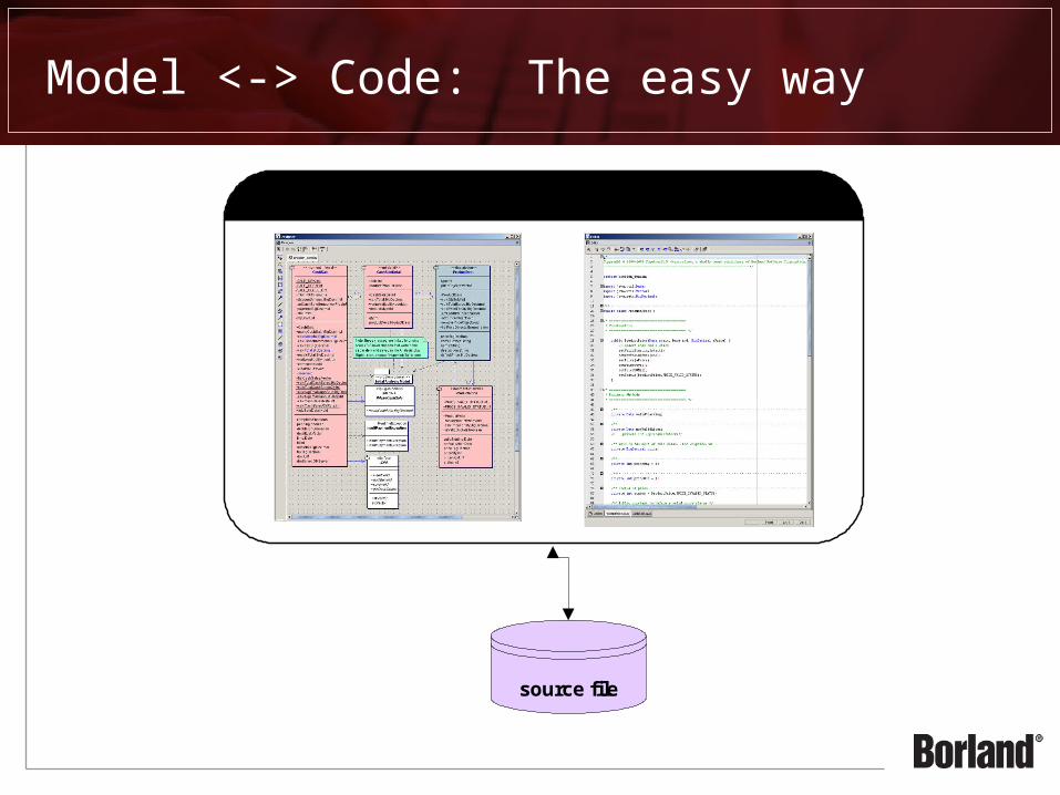
Model <-> Code: The easy way
Model and Code
source file

Why does an Analyst model?
Document agreement on what the Business wants to accomplish Remove ambiguity Enable the “Big Picture” view of the Business
In combination with plain text Large volume of requirements difficult to consume as a whole Modeling provides constructs to help organize ideas Visualization helps clarify complex ideas Standards bring focus to key abstractions
In contrast to ad-hoc diagrams Standards facilitate precise communication Common language for all members of the team

Analysis

Why does an Architect model?
Design Overall Application Architecture
Mapping design to requirements
Effectively develop and communicate design
Documenting design and architecture
Ensure quality of design Provide architectural views
Leverage Reuse Established frameworks Existing libraries Design patterns
Engineer a Produceable System Can be built with
development constraints Business: time and money People: knowledge and skill
sets Process: quality and
predictability Technology: tools and
existing systems Can withstand changes
over time New features or changing
requirements Updated IT infrastructure

Design

Why does a Developer model?
Implementation Options Explore options Need strong refactoring
support Improve design without
changing functionality
Code reviews are time consuming and inefficient
Adherence to corporate or industry best-practices
Code can be maintained, modified, and reused
Document the System Large code bases are
difficult to understand Understand dependencies Understand interfaces
So we can start parallel development by just knowing the contract for a component

Implementation

How do the Together® products work?

A Brief Introduction to UML
Use Case Diagrams Who cares about what?
Activity Diagrams How is it done?
Class Diagrams What are the pieces?
Interaction Diagrams What interactions need to
happen?

Use Case Diagram
“Who cares about what?”
What value will the user derive from the system?
What kinds of users need to interact with the
system?
What major capabilities of the system can be
reused?

Activity Diagrams
“How is it done?”
What is the flow of activities in the
system?
What activities will the system perform?
What “artifacts” might the system
generate?

Class Diagram
“What are the pieces?”
What are the major concepts the system will
need to understand?
How are those concepts related to other
concepts?

Sequence Diagram
“What interactions need to happen?”
What responsibilities do the parts have?
How will the parts accomplish their responsibilities
through interactions with other parts?

Other UML Diagrams
UML helps capture key aspects of a system from multiple viewpoints.
StructuralView
ImplementationView
BehavioralView
EnvironmentView
User View
Activity DiagramsSequence DiagramsCollaboration DiagramsState Machine DiagramsInteraction Overview Diagrams
Composite Structure DiagramPackage DiagramsObject DiagramsClass Diagrams
Component Diagrams
Deployment Diagrams
Use Case Diagrams

UML™ Modeling with LiveSource™
Together® LiveSource™ technology: UML™ Class diagrams are a live rendition of the underlying
source code Model to Code. Code to Model. Always in sync.
IncrementalIncrementalCodeCode
GeneratorGenerator
TogetherTogether®®
ParsingParsingEngineEngine
LiveSource™

Together® Documentation Generation
Model and code always in sync +
Documentation generated from model =
Documentation always accurate and up-to-date!
Together® generates: HTML RTF TXT PDF
Custom template designer
Post for team daily

Together® Design Pattern Support
Reuse existing, trusted solutions Gang of Four (GoF) patterns Sun Java™ Center J2EE™ patterns Your own custom patterns!

Quality Assurance
Audits and metrics help automate the assessment of software design and implementation quality.
Audits Enforce coding standards Detect deviation from established best-practices Streamline code reviews
Metrics Quantitative OO design analysis Improve maintainability Guide refactoring

Additional Topics

What’s New in Together 2006
Deep integration with Eclipse 3.1 (perspectives, activatable capabilities, leveraging Eclipse project natures, etc)
Model-Centricity (model is a tangible, usable artifact, not just a collection of diagrams)Diagramming usability improvements (layouts, rulers and guides, alignment, match
width/heightModel Driven Architecture support (UML 2.0, OCL 2.0, QVT, XMI 2.0)Business Process modeling support (BPMN, generate BPEL)Data Modeling support (ER diagramming, transformations)UML 2.0 modelingModel Audits and Metrics (defined in OCL)UML Profiles and profile definition projects supportNew patterns and pattern definition projects supportMDL and MDX import; XMI 2.0 model interchangeNew requirements integration with CaliberRM and RequisiteProGeneration of template-based documentationLiveSource™ (simultaneous round-trip engineering) with Java 5

General Modeling Features
Usability ImprovementsLaser Sighting
• visual indication of element alignment – edges or centersMultiple Layout Algorithms
• Hierarchical, Tree, Orthogonal, Spring Embedder, Together• Permits layout of contained elements
Automated Element Resizing and Aligning• Align (Left | Center | Right | Top | Middle | Bottom)• Match Width or Height• Order Links
Ctrl-Click “model” lets you rapidly create multiple elementsModel Bookmarks

Extensive Search Capabilities
Search:
Model
Model using OCL
Files
Java
CaliberRM
StarTeam
Search output:
Multiple Result Sets
Saves history

Documentation Template Designer
Feature-rich documentationtemplate designer
Functionally equivalentto Together ControlCenterexcept now:
Supports all models:UML Design (1.4 and 2.0),UML LiveSource™, BP, Data
Embed OCL queries

Multiple Project Types
Eclipse paradigm is essentially lots of little projects
(as opposed to former ControlCenter/Architect 1.x which only opened a single project at a time)

Business Process Modeling Project
Only one diagram type: business process diagram
Real-time model validation features Invalid elements drawn in red on diagram Auto-fix element Validate against BPMN spec or for
export to BPEL4WS

Data Modeling Project
Only one diagram type: Entity Relationship (ER)
but available in both logical and physical and can benotated using IE or IDEF1X
Automated transformations between logical and physical
Generate SQL or DDL
Target servers: Generic SQL, IBM DB2 8, InterBase 7, JDataStore 7, MS Access, MS SQL Server 2000, mySQL 4, Oracle 9, Sybase AS Anywhere 8, Sybase AS Enterprise 12

Java Modeling Project
UML 1.4 project with LiveSource™ class diagrams
Use Case, Activity, State, Sequence, Collaboration, Component, Deployment, Class diagrams
Generate Sequence diagramsDesign PatternsPattern RecognitionCode Audits and MetricsAdd Linked

Java Modeling projects from Java projects
Simply add Java Modeling project nature to an existing Java project (does not create a new project)

MDA Transformation Project
Eclipse plug-in project with QVT Builder
Three transformation types:QVT TransformationQVT LibraryModel to Text Transformation
optionally using JET (Java Emitter Templates)
Can be developed interactively – fully-featured code editing, debugger, compiling
Run from workspace, deploy as compiled transformation or automate via Ant script

Pattern Definition Project
Java modeling project with a UML Profile to support pattern definition, development and deployment
Three ways to create these:
Can be created from scratch – File New… Project…
Created from selected elements in a model select elements, Export to Pattern Definition Project
Generated from a deployed pattern in the Pattery Registry view Choose Edit Definition from pattern’s context menu

Profile Definition Project
Java modeling project with a UML Profile to visually model UML Profile definitions
Create custom stereotypes, tagged values, palette entries (custom icons on the diagram palette) and viewmapping (such as custom colors and icons)
Can also include shortcuts to metaclasses as well as model profile constraints in OCL
After applying a profile to a model, one can validate the model against the profile’s constraints

UML 1.4 Project
Design project containing UML 1.4 diagrams: use case, activity, class, sequence, collaboration, state, component and deployment
Provides model audits and metrics, exposes metamodel, can be used in model-to-model and model-to-text transformations
Important note: UML 1.4 metamodel is provided as is, and no improvement are planned for future releases.

UML 2.0 from 1.4 Project
Automate conversion of UML 1.4 design projects to UML 2.0
Sleeper feature? This wizard does an excellent job mapping from UML 1.4 constructs to UML 2.0. Many other competitor products struggle with this.

UML 2.0 Project
Design project containing UML 2.0 diagrams: activity, class, component, communication, composite structure, deployment, sequence and statemachine
Provides model audits and metrics, exposes metamodel, can be used in model-to-model and model-to-text transformations

Together Project Summary
Multiple projects exist in a common workspace shared between roles
roles see a “logical view” of workspace (e.g., only applicable project types)
accessible and referenceable cross-project shortcuts are only possible for Classes and Interfaces.
This will be fixed in a Q4 05 service pack
generated documentation can include all projects in the workspace

Together Advanced Features

Model Audits and Metrics
New in Together 2006!Expressed in OCL; easy to write, customize and deploy across
teamsReap enormous benefits by improving quality as early as possibleModel Audits provide design inspections for model elements
Pulled from David Frankel, Scott Ambler, Robert Martin and others
Best practices for design elements
Model Metrics provide measurements of models Version 1.0, rather simple for now. Expect this feature to grow!
Model Audits and Metrics combine to provide an accurate assessment of how “complete” your model is. This has historically been a very difficult thing to determine.

Model Audits - Sample
“Black Hole” State
OCL Audit Definition

Code Audits and Metrics
Mature API to inspect and measure Java modeling projectsAutomate low-level parsing for potential errors, coding
standards, design flaws and adherence to Java best practicesAccurately measure object-oriented attributes such as coupling,
cohesion, encapsulation and inheritanceImprove quality of projects – developers can include audits in
their workflow, project leads can measure the whole projectAssess the quality of code contributed by remote teams, inherited
components or as an aid to maintenance effortsAutomate reporting using command-line – include in daily builds

Code Quality Assurance
Audits Java Auto-Correct API
Metrics Java API Kiviat View
Reporting GUI and command-line driven

Design Patterns

What is the Value of Design Patterns?
Design Patterns provide common, sometimes even industry standard, design solutions to everyday problems
Improve communication through abstraction Describing a solution in aggregate is less complex than
describing all the details about how it works e.g., “I’m using a Visitor to assess the inventory…” vs. “we have
a provided a common interface for all objects in the inventory so we can later use a common access method to parse the contents within the inventory…”

What is the Value of Design Patterns in Together?
Together bundles the most-common design patterns Gang of Four (GoF) J2EE Design Patterns
Together lets you model and deploy your own patterns Wrap your internal best practices and design solutions as
repeatable, reusable patterns
Together can discover pattern usage in existing source code Leverage the benefits of visualizing pattern usage to better
understand reverse engineered code

Using Design Patterns
Interactive chooser dialog
Browse available patterns
View pattern description
Set pattern parameters

Using Design Patterns - visualization
Collaboration bubble can reduce visual complexity
Lets you view the pattern as a whole

Product Demo