TO STUDY THE CHARACTERISTICS OF...
74
TO STUDY THE CHARACTERISTICS OF ELECTROENCEPHALOGRAM (EEG) AND ITS ASSOCIATED ARTIFACTS (SATU KAJIAN TENTANG CIRI ELECTROENSEFALOGRAM (EEG) DAN ARTEFAK YANG BERKAITAN) NORANI HAMZAH SALWANI MOHD. DAUD SALMIAH BASIR Jabatan Kejuruteraan Elektrik Kolej Sains dan Teknologi Universiti Teknologi Malaysia VOT 75035 RESEARCH VOTE NO: 75035 2006
Transcript of TO STUDY THE CHARACTERISTICS OF...

TO STUDY THE CHARACTERISTICS OF ELECTROENCEPHALOGRAM (EEG) AND ITS
ASSOCIATED ARTIFACTS
(SATU KAJIAN TENTANG CIRI ELECTROENSEFALOGRAM (EEG) DAN
ARTEFAK YANG BERKAITAN)
NORANI HAMZAH SALWANI MOHD. DAUD
SALMIAH BASIR
Jabatan Kejuruteraan Elektrik Kolej Sains dan Teknologi
Universiti Teknologi Malaysia
VOT 75035
RESEARCH VOTE NO: 75035
2006

ii
To those whom had contributed to this works. May Allah bless all of us.

iii
ACKNOWLEDGEMENTS We would like to thank our neurologist colleagues in few hospitals for their information on EEG and the precautions to be taken during recording sessions. We are also indebted to Universiti Teknologi Malaysia (UTM) for the provision of this fundamental research funding from Ministry of Higher Education. Our special thanks to the Librarian in Perpustakaan Sultanah Zanariah UTM for their commitment in obtaining the related literatures for our research works. Last but not least to all of my friends that are not possible to be listed here, whom had supported and encouraged us, may Allah bless all of you.
iv
ABSTRACT
TO STUDY THE CHARACTERISTICS OF ELECTROENCEPHALOGRAM (EEG) AND ITS ASSOCIATED ARTIFACTS
Electroencephalogram (EEG) measures brain function by analyzing the scalp electrical activity generated by brain structures. Local current flows are produced when brain cells (neurons) are activated. However, only electrical activity generated by large populations of neurons concurrently active can be recorded on the head surface. The small electrical signals detected by the scalp electrodes are amplified thousands of times, then displayed on paper or stored to computer memory.
EEG like all biomedical signals is very susceptible to a variety of large signal contamination which reduces its clinical usefulness. Many researches had discovered that EEG signals are noisy and non-stationary. These EEG signals are contaminated by artifacts due to blinking, eyeball movements and muscle movements. However the main contamination is due to ocular artifacts elicited by blinking and eyeball movements.
This research proposed a novel approach of adopting lifting wavelet transform (LWT) to eliminate ocular artifacts. Three basic steps involved were to transform the EEG, hard thresholding the wavelet coefficients and the corrected EEG was obtained by inverse transform these threshold coefficients. It is of paramount important to select a suitable wavelet and threshold value to accomplish this task. Thus, to select a wavelet for artifact removal in electroencephalogram using this method, relative wavelet energies were determined before and after thresholding. Relative wavelet energy (RWE) gives information about the relative energy associated with different frequency bands and can be considered as a time-scale density. RWE can be used as a tool to detect and characterize a specific phenomenon in time and frequency planes. This study concluded that cdf4.4 outperformed db4 and haar wavelets by removing the artifacts at the correct times and frequency bands.
(Keywords: EEG, lifting wavelet transform, ocular artifacts, relative wavelet energy)
Key researchers :
Pn. Norani Hamzah Assoc. Prof. Salwani Mohd. Daud
Pn. Salmiah Basir
E-mail : [email protected] Tel. No. : 03-26154662 Vote No. : 75035
v
ABSTRAK
SATU KAJIAN TENTANG CIRI ELECTROENSEFALOGRAM (EEG) DAN ARTEFAK YANG BERKAITAN
Electroensefalogram (EEG) mengukur fungsi otak dengan menganalisis aktiviti
elektrik yang dihasilkan oleh struktur otak. Arus setempat yang mengalir dihasilkan oleh sel otak yang aktif. Bagaimanapun, hanya aktiviti elektrik yang dijana oleh populasi neuron yang besar boleh direkodkan dari permukaan kepala. Isyarat elektrik yang kecil dikesan oleh elektrod scalp dikuatkan beberapa ribu kali ganda, kemudian dipaparkan atau distorkan ke dalam memori computer.
EEG sebagaimana isyarat biomedikal yang lain sangat lemah kepada isyarat hangar yang lain yang boleh mengurangkan kegunaan klinikal. Ramai penyelidik telah mendapati yang isyarat EEG adalah terlalu hingar dan tidak diam. Isyarat EEG dicemari oleh artefak yang terhasil daripada kelipan matan, pergerakan bebola mata dan pergerakan otot. Namun demikian hingar utama adalah daripada artefak okular.
Penyelidikan ini mencadangkan satu pendekatan baru untuk mengenepikan artefak okular dengan menggunakan penukaran wavelet meningkat. (LWT). Tiga langkah asas yang terlibat dalam LWT ialah penukaran isyarat EEG, penghad aras koefisyen wavelet dan EEG yang bersih didapati dengan menukar semula koefisyen yang sudah dibersihkan daripada hingar. Penggunaan wavelet dan had aras yang sesuai adalah sangat penting. Jadi tenaga wavelet relatif (RWE) dikira sebelum dan selepas pendekatan ini untuk menentukan wavelet yang sesuai. RWE memberi maklumat tentang tenaga relatif yang berkaitan dengan setiap jalur frekuensi yang berlainan dan boleh dianggap seperti density skala-masa. RWE boleh dijadikan sebagai alat untuk mengesan dan membentuk satu fenomena yang spesifik dalam plane masa dan frekuensi. Kajian ini merumuskan cdf4.4 adalah leih baik daripada wavelet db4 dan haar untuk mengenepikan artefak okular pada jalur masa dan frekuensi yang tepat. (Katakunci: EEG, penukaran wavelet angkat lifting, artefak okular, tenaga wavelet relatif)
Penyelidik utama :
Pn. Norani Hamzah Prof. Madya Salwani Mohd. Daud
Pn. Salmiah Basir
E-mail : [email protected] Tel. No. : 03-26154662 Vote No. : 75035

vi
TABLE OF CONTENTS
CHAPTER TITLE PAGE
DEDICATION ii
ACKNOWLEDGEMENTS iii
ABSTRACT iv
ABSTRAK v
TABLE OF CONTENTS vi
LIST OF FIGURES viii
LIST OF SYMBOLS x
LIST OF ABBREVIATIONS xi
LIST OF APPENDICES xii
1 INTRODUCTION 1
1.1 Introduction 1
1.2 Objectives of the Study 2
1.3 Main Contributions 3
1.4 Outline of Thesis 4
2 LITERATURE REVIEW 5
2.1 Introduction 5
2.2 Previous Works on OA Elimination 6
3 ALGORITHM AND METHODOLOGY 7
3.1 Introduction 7
3.2 Wavelet Denoising 10
3.3 Relative Wavelet Energy 11
3.4 Methodology 12
3.4.1 Determine the Threshold 12

vii
3.4.2 EEG Recordings 13
4 RESULTS AND DISCUSSIONS 15
4.1 Experimental Results 15
4.2 Discussions 26
5 CONCLUSIONS AND FUTURE WORKS 27
5.1 Conclusions 27
5.2 Future Works 27
REFERENCES 28
Appendix 30

viii
LIST OF FIGURES
FIGURE NO. TITLE PAGE
2.1 10-20 electrode placement 5
(F: Frontal, C: Central, T: temporal, P: Parietal and O: Occipital. The letters are accompanied with numbers by odd number at the left side of the head and even number at the right side of the head)
3.1 One step forward lifting operation 8 3.2 Inverse lifting step 8 3.3 Wavelets (a) Haar, (b) cdf4.4 and (c) db4 10 3.4 Mindset 24 13 3.5 A subject wore electrode cap during 14
recording session 4.1 Ocular artifacts at most affected channels in 16
FP1, FP2, F7 and F8
4.2 Corrections made for every frequency bands 17 for segment 1 for every frequency band using Haar wavelet
4.3 Corrections made for every frequency bands 18
for segment 1 for every frequency band using cdf4.4 wavelet
4.4 Corrections made for every frequency bands 19 for segment 1 for every frequency band using db4 wavelet
4.5 Relative wavelet energy, RWE for channel 20
FP1 for all frequency bands obtained using Haar wavelet

ix
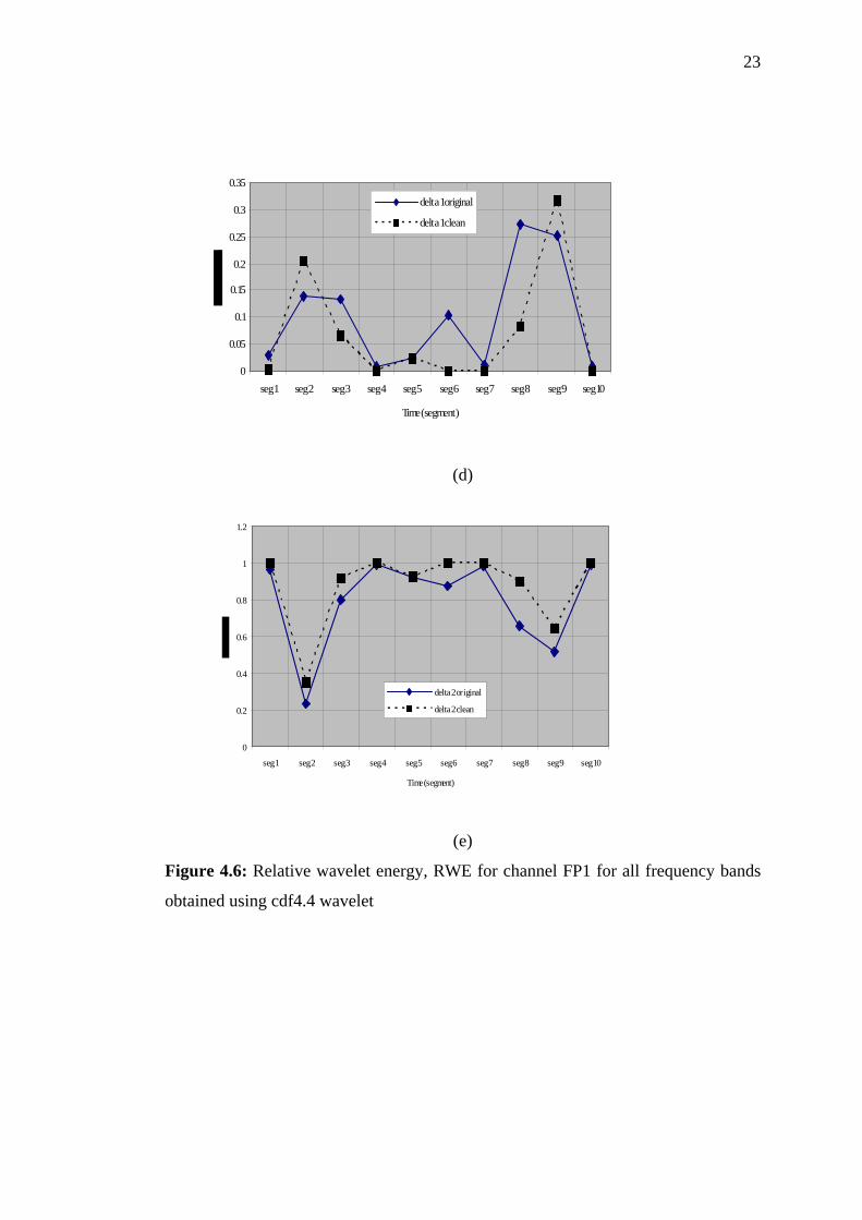
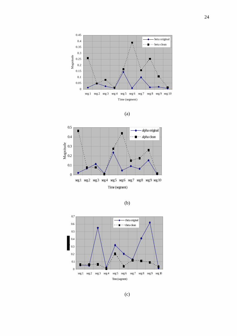
4.6 Relative wavelet energy, RWE for channel 23
FP1 for all frequency bands obtained using cdf4.4 wavelet
4.7 Relative wavelet energy, RWE for channel 25
FP1 for all frequency bands obtained using db4 wavelet

x
LIST OF SYMBOLS
1+ja - approximation coefficients
1+jd - detail coefficients
),( gh - analysis filters
)~,~( gh - synthesis filters
jT - threshold
)(kD j - wavelet coefficients
ijE - energy at each time segment
ijp - relative wavelet energy
FP1 - EEG recording channel FP2 - EEG recording channel F7 - EEG recording channel F8 - EEG recording channel

xi
LIST OF ABBREVIATIONS
EEG - electroencephalogram EOG - electrooculogram OA - ocular artifact PCA - principal component analysis ICA - independent component analysis USA - United States of America WT - wavelet transform MRA - multiresolution analysis RWE - relative wavelet energy

xii
LIST OF APPENDICES
APPENDIX TITLE PAGE
A Mindset 24 – Specifications 30
CHAPTER 1
INTRODUCTION 1.1 Introduction
Electroencephalogram (EEG) measures brain function by analyzing the scalp
electrical activity generated by brain structures. Local current flows are produced
when brain cells (neurons) are activated. However, only electrical activity generated
by large populations of neurons concurrently active can be recorded on the head
surface. The small electrical signals detected by the scalp electrodes are amplified
thousands of times, then displayed on paper or stored to computer memory.
EEG like all biomedical signals is very susceptible to a variety of large signal
contamination which reduces its clinical usefulness. Many researches had
discovered that EEG signals are noisy and non-stationary. It is very important to
ensure a true EEG signal is generated from the brain, however this is not possible as
there exist artifacts that suppresses the EEG signals. These artifacts are generated by
non-neural sources like muscle movements, heart beat, eye movements and
perspiration [1]-[6]. However EEG is dominantly affected by eye movement such as
blinking and eyeball movements [1]-[6]. These movements elicit voltage potential
known as electrooculogram (EOG) that spread across the scalp and contaminate the
EEG and is referred as ocular artifact (OA) [1]-[6].
Wavelet transform has emerged as one of the superior technique in analyzing
non-stationary signals like EEG. Its capability in transforming a time domain signal
into time and frequency localization helps to understand more the behavior of a

2
signal. For instance, the occurrence of OA in the EEG signal can be clearly
recognized when this signal is decomposed into few levels with different scales.
LWT is known as second generation wavelets that do not shift and translate as in the
first classical multiresolution-based wavelets. LWT had simplified the computation
mechanism and it is suitable for real-time applications [8]–[11].
1.2 Objectives of the Study
An investigation of OA removal using Lifting Wavelet Transform (LWT)
since wavelet transform do not rely on visual inspection and reference EOG channel
[7] will be implemented in this research. Wavelet denoising technique introduced by
Donoho and Johnstone [11]-[13] has been employed in this study. To get a
satisfactory result of OA removal, it is of paramount important to use a suitable
wavelet and threshold value. A tool namely relative wavelet energy, RWE to
compare the effectiveness of the wavelets was adopted in this thesis. RWE is
considered as time-scale density that can be used to detect a specific phenomenon in
time and frequency planes [14]-[15].
(i) To record EEG signals from the scalp.
(ii) To analyze the properties of the EEG and its associated artifacts using
MATLAB.
(iii) To compare effectiveness of few wavelets in eliminating the ocular
artifacts.
1.3 Main Contributions
There are three main contributions of the thesis. First, some recorded data
samples of EEG signals from few subjects are stored for future investigations.
Second, it can be concluded that cdf4.4 outperformed db4 and haar wavelets in
removing the artifacts at correct times and frequency bands. Third, the study show
3
the effectiveness of adopting lifting wavelet transform with the threshold determined
in the study.
1.4 Outline of Thesis
This thesis is organized in five chapters. Chapter 2 starts with some
background on electroencephalogram and explanations on some common artifacts
that exist together with EEG. Previous research works on ocular artifacts are also
discussed.
Chapter 3 discusses the methodology used for the study and explanation on
wavelet transform is presented here. Chapter 4 presents the analysis on the
experimental results obtained. Finally, Chapter 5 concludes the research works with
suggestions on some future works that can be improved.
CHAPTER 2
LITERATURE REVIEW 2.1 Introduction
Ocular artifact is due to voltage potentials elicited when the eye blinks and
moves (round, horizontal and vertical movements). Cornea in human eye is having a
positive charge while retina with negative charge [1]-[6] produces a potential
difference of about 100mV between them [1], [3]. Thus eye movements and
blinking can easily generate the voltage potential known as EOG. Consequently, this
EOG spread across the scalp to contaminate the neural potentials, EEG. Many
researchers had reported that ocular activity occur in low frequency bands, below 5
Hz [1]-[2], but in the same study made by the researchers [2], suggested that
although largest effect is in delta and theta band, there is also some considerable OA
effect in alpha and beta bands. Hence there is a basis of not ignoring the upper
frequency band; in alpha and beta bands when analysis on OA is done [1]-[2].
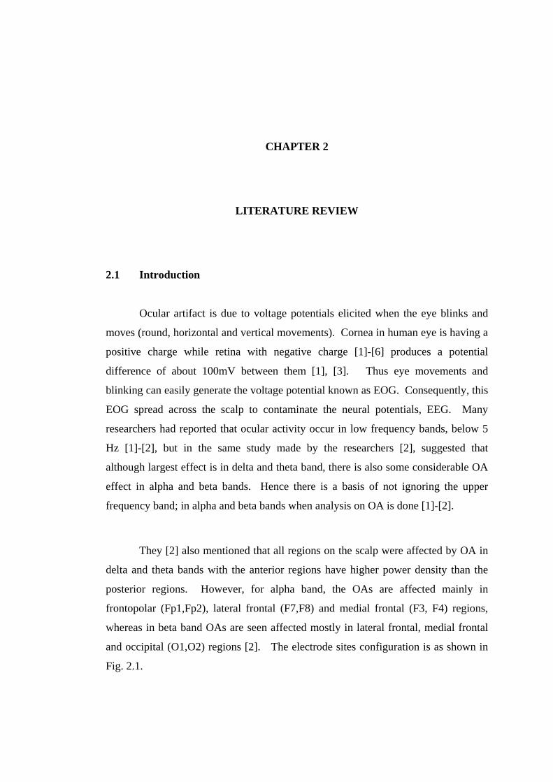
They [2] also mentioned that all regions on the scalp were affected by OA in
delta and theta bands with the anterior regions have higher power density than the
posterior regions. However, for alpha band, the OAs are affected mainly in
frontopolar (Fp1,Fp2), lateral frontal (F7,F8) and medial frontal (F3, F4) regions,
whereas in beta band OAs are seen affected mostly in lateral frontal, medial frontal
and occipital (O1,O2) regions [2]. The electrode sites configuration is as shown in
Fig. 2.1.

5
Blinking generates spike-like shapes [1]-[6] with their peaks can reach up to
800 uV and occur in a very short period, 200 – 400 ms [2]. Eye movements produce
square-like waves with smaller magnitude and longer duration [1]-[6].
It has been accepted clinically that eyeball make a momentary upward
rotation when the eyelid blink, hence the potential change produced is augmented by
the effect of eyelid movement [1], [3], [5]-[6]. Evinger et al [3] had reported that a
slight downward rotation of the eyes also accompanied by blinks. This finding allow
researchers to eliminate OAs in the EEG by considering only one threshold value for
a frequency band as proposed in this study.
Fig. 2.1 Electrode Placement (top view)
(F: Frontal, C: Central, T: temporal, P : Parietal and O: Occipital. The
letters are accompanied with numbers by odd number at the left side of
the head and even number at the right side of the head)

6
2.2 Previous Works on OA Elimination
There are two general methods of removing the artifact. The simplest method
is to reject epochs contaminated with OA. The method is fast and easy to implement
but it is not practical to be adopted for real-time application. It also results loss of
important data if these contaminated epochs are rejected. Thus this approach is
unlikely to be a good choice since blinking and eye movements are involuntary
movement that can occur very frequent.
The second approach is using some complex algorithm of OA removal to
obtain corrected EEG [39]-[41]. Some of the techniques used for OA removal or
EEG correction are regression, adaptive filtering, principal component analysis
(PCA) and independent component analysis (ICA) [44]. Adaptive filtering requires a
reference electrooculogram channel to remove the artifact, but a pure EOG signal
that contains only ocular artifact is impossible to obtain [44]. ICA is not automated
since it requires visual inspection to select their independent components for
correction [45] and it was noted by Wallstrom et al. [44] that ICA correction
distorted power for a frequency range between 5 Hz – 20 Hz. PCA cannot
completely separate OAs from the EEG signals especially when they have
comparable amplitudes [45]. Hence, there is still a major challenge in developing a
technique to a successful removal of OAs from EEG recordings. This thesis will
present an approach to remove ocular artifacts with the adoption of lifting wavelet
transform.

CHAPTER 3
ALGORITHM AND METHODOLOGY 3.1 Introduction
Lifting scheme was introduced by Sweldens in 1995 had simplified the
mechanism in constructing wavelets and this approach becomes more practical to be
realized for real-time applications [8]–[11]. The scheme does not require the
information in Fourier transform because the wavelet transform can be implemented
in spatial or time domain [8]-[11]. The basic steps in lifting operations [8]-[11] are:
(i) Split: The original signal of length n where n = 2j is separated into two disjoint
sets of even and odd samples.
(ii) Predict: The predict step replaces the odd element with this difference as in
Eqn.(1) and can be considered as high frequency or detail components.
Therefore the predict step can be viewed as high-pass filter. This is done by the
following equation:
])[(][][1 nxPnxnd eoj −=− (3.1)
where P is the predict operator.
3) Update: This step replaces the even element with an approximation that is the
signal becomes smoother compare to the previous scale. Hence this operation is
viewed as low-pass filtering since the smoother signal contains fewer high
frequency components. The update equation is as follows:
])[(][][ 11 ndUnxna jej −− += (3.2)
where U is the update operator.
4) Normalization: The approximation and details coefficients must be normalized in
the final step of the transformation.

8
The lifting step is depicted in Figure 3.1 for the decomposition or analysis of the
forward wavelet transform. The update and predict stages can become a pair but
sometimes they may not be together in a lifting step.
Split P U][
][na
nx
j
1−ja
1−jd
even elements
odd elements
Figure 3.1: One step forward lifting operation
To obtain the signal back, the operations can be undone by just reversing them and
change the signs as shown in Fig. 3. The operation is working backwards from the
forward lifting operation.
MergePU][
][na
nx
j
1−ja
1−jdodd elements
even elements
Figure 3.2: Inverse lifting step
In the inverse step, the update step is followed by predict step and finally the odd and
even components are merged which interleaves the odd and even elements back into
one data stream. The equation for the inverse lifting steps are given by:
])[(][][ 11 ndUnanx jje −− −= (3.3)
])[(][][ 10 nxPndnx ej += − (3.4)

9
If more steps are required, they can be added singly. The first generation
wavelets can be converted into lifting steps by factoring its h-coefficients as shown
in many texts [8]-[11]. Few wavelets used in this study had be factorized into lifting
steps and their lifting coefficients are as follow:
1) Haar
‘p’ : -1 and ‘u’: 0.5,
normalization: [1.414, 0.707].
2) Cohen,Daubechies,Feauveau, cdf4.4
‘u’: [-0.25 -0.25]
‘p’: [-1 -1]
‘u’: [-0.039 0.226 0.226 -0.039]
normalization: [2.828, 0.3535]
3) Daubechies, db4
'p': [ -0.322]
'u': [ -1.117 -0.300]
'p': [ -0.018 0.117]
'u': [2.131 0.636]
'p': [-0.469 0.140 -0.024]
normalization: [0.734, 1.362]
(Note: ‘p’ is predict and ‘u’ is update)
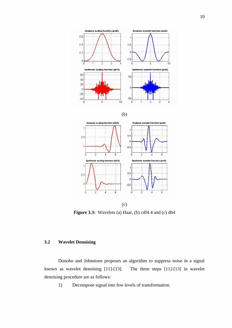
These wavelets are shown in Figure 3.3(a)-(c) for analysis and synthesis
transformation.
(a)
10
(b)
(c)
Figure 3.3: Wavelets (a) Haar, (b) cdf4.4 and (c) db4
3.2 Wavelet Denoising
Donoho and Johnstone proposes an algorithm to suppress noise in a signal
known as wavelet denoising [11]-[13]. The three steps [11]-[13] in wavelet
denoising procedure are as follows:
1) Decompose signal into few levels of transformation.
11
2) Apply a threshold function to the detail coefficients by comparing
with a threshold value, i.e. coefficients greater than the threshold will
be eliminated (set to zero).
3) The corrected signal is obtained by inverse transformed of the
threshold coefficients.
An adaptive wavelet denoising was employed since the threshold value was
determined separately for every level of decomposition. The threshold was based
upon the statistical properties of the wavelet coefficients; mean and standard
deviation values.
3.3 Relative Wavelet Energy
It is inherently difficult to evaluate the successful of OA correction using
different type of wavelets. Croft and Barry [4] had reported that since there is no
correlation between EOG and uncontaminated EEG, then correlation between low
EOG and corrected EEG can be used as a criterion to assess the effectiveness of the
method used, but it is still not a refined measure of validation. They [4] also
suggested the most useful form of validation is corrected EEG should be reasonably
visualized. Thus we use a tool, relative wavelet energy to assist us to choose an
effective wavelet in our technique. RWE gives information about relative energy
with associated frequency bands and can detect the degree of similarity between
segments of a signal [14]-[15]. For this study we determine relative energies for
every band before and after thresholding to compare the similarities and
effectiveness of each wavelet used to remove the artifacts. RWE is defined as
follows:
tot
j
EE
RWE = (3.5)
with the energy of the detail signal at each resolution level, j is
∑=
=J
jjj kDE
1
2)( (3.6)
12
and the total energy for all levels is given by:
∑∑∑ ==j
jj k
jtot EkDE2
)( (3.7)
3.4 Methodology
3.4.1 Determine the Threshold
The EEG signals from Fp1, Fp2, F7 and F8 channels were decomposed to
seven levels of interest that can be considered as beta, alpha, theta and delta
frequency bands. According to Nyquist criterion, the maximum frequency in a
signal is half of the sampling frequency (in this case, Fs= 256 Hz), thus the beta band
occupies in 16 – 32 Hz, alpha band in 8 – 16 Hz, theta band in 4 – 8 Hz, delta 1 band
in 2 - 4 Hz, and delta 2 band associates with 0 – 2 Hz of frequency ranges after the
decomposition.
A clean signal (no presence of blinking and eye movements) from the same
channel of another recording trial was used to determine the threshold. The signal
was decomposed for every one second epoch, hence we obtained 10 segments since
the EEG signals were recorded for ten seconds. There were ten segments with
different values of mean and standard deviation for bands 3 to 7. Finally the
threshold for each band, k of concern was determined by taking the mean and
standard deviation of maximum absolute value, Mk of detail coefficients from all
segments:
)(*2)( kkk MstdMmeanT += (3.8)
The threshold chosen must remove the OAs at the correct times and frequency bands
of the particular signal.

13
3.4.2 EEG Recordings
The EEG was recorded according to this controlled environment. Subject
was seated comfortably on a recliner chair in a dim, acoustic laboratory with air-
condition switched off, and scalp electrodes according to standard 10-20
configuration (Figure 2.1) from Electro-Cap International, Inc. connected to two
electrically linked mastoids at A1 and A2. All electrode impedances were measured
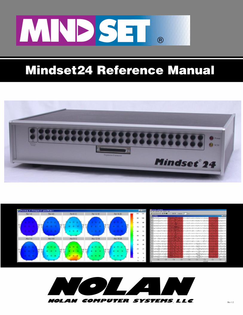
below 1 kΩ and they were connected to Mindset 24 as shown in Figure 3.4 for EEG
acquisition. The subject was asked to perform a mental task with eyes opened and
were repeated for five times. During the recording, the subject was asked to focus
his/her eyes on the computer monitor and follow the instructions given by a stimulus
program. Data was sampled at 256 Hz and the recording was done for 10 seconds
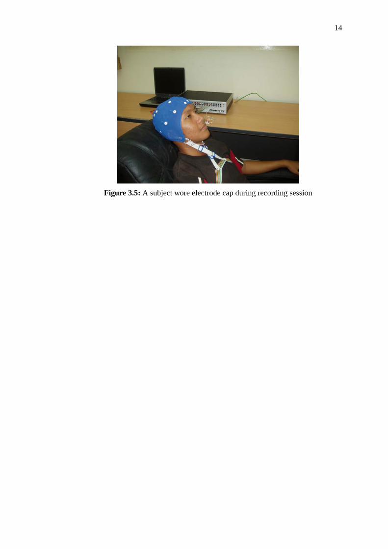
for the task, thus there were 2560 data samples for the channel. Figure 3.5 shows
one of the subject during EEG recording sessions.
Figure 3.4: Mindset 24
14
Figure 3.5: A subject wore electrode cap during recording session

CHAPTER 4
RESULTS AND DISCUSSIONS 4.1 Experimental Results
From Figure 4.1, there were OAs exist in the signals for few selected
channels for all segments except segment 5 can be considered free of all artifacts.
The waveforms shown in Figure 4.1 are from channels FP1, FP2, F7 and F8 which
are considered the most affected channels by OAs.
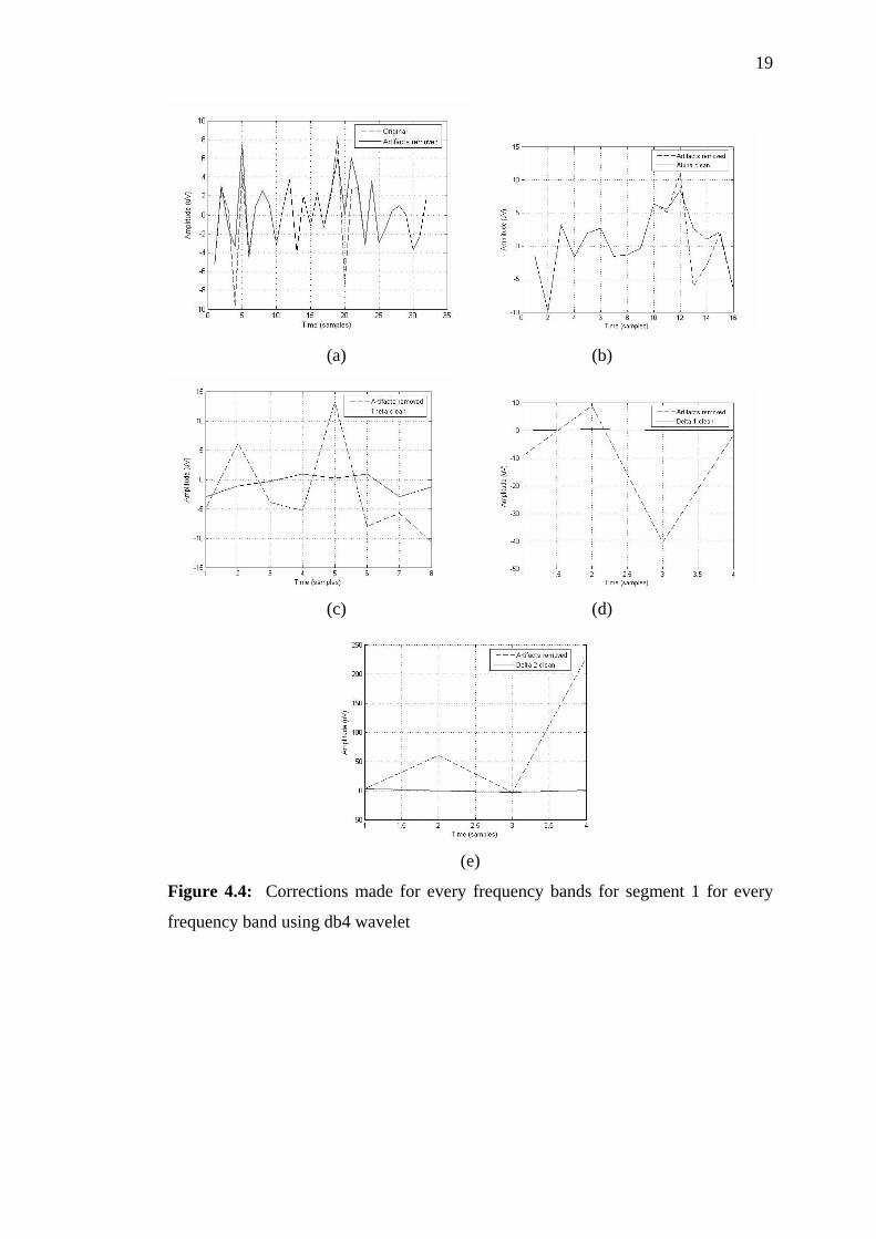
Then Figures 4.2 to 4.4 illustrate waveforms before and after threshold for
each type of wavelet used for segment 1 (0 to 1 second). These figures depict the
thresholding occurred in the segment for channel FP1. It can be concluded that the
waveforms appear reasonable and corrections had been made at the right frequency
band and space localization for all wavelets since blinking and eye movement
present in this segment. It can be seen that most contamination was in delta and theta
ranges, with some of OA effect in alpha and beta bands for FP1 channel. These
results were consistent with the findings reported by the Hagemann and Neumann
[2].
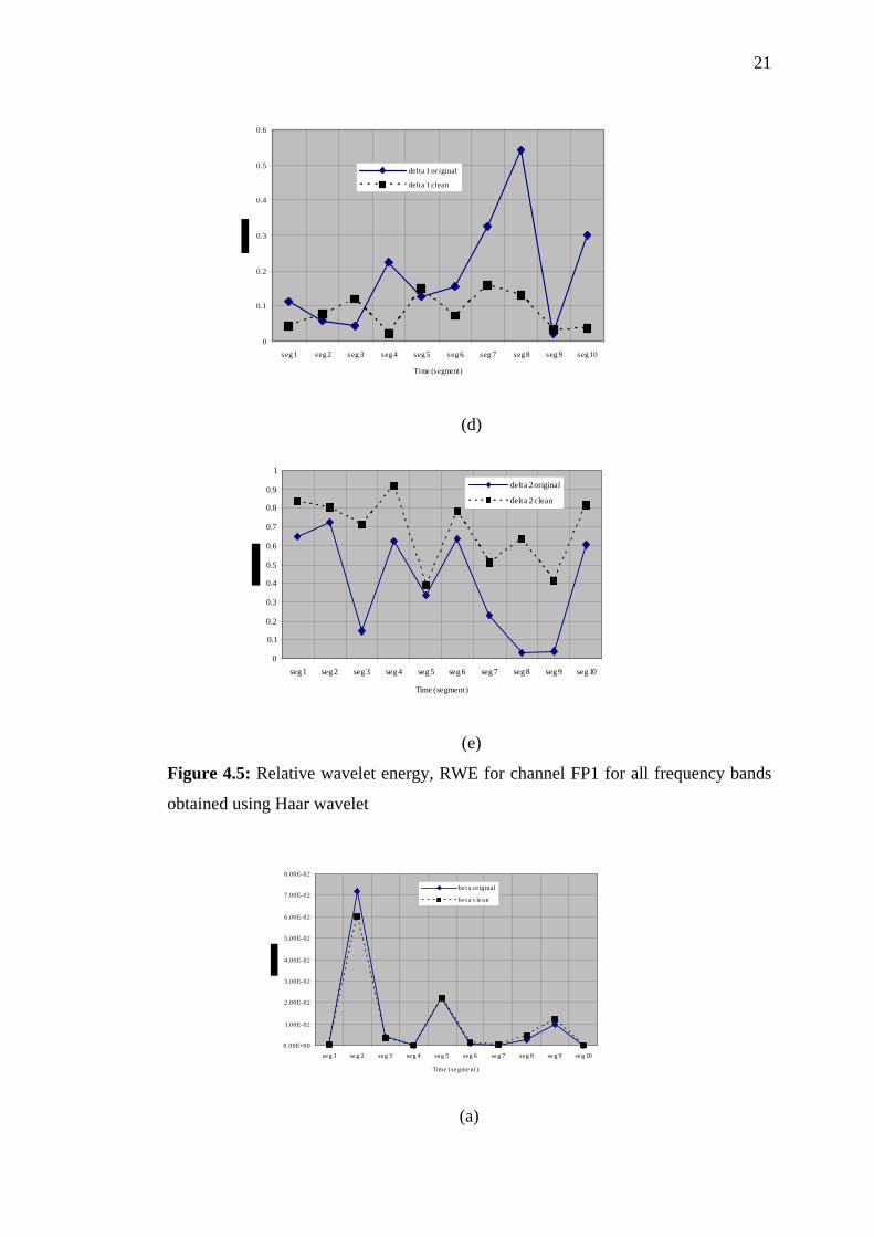
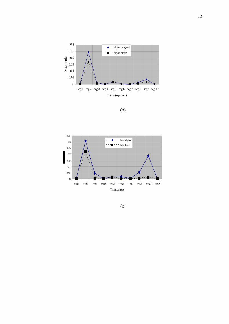
From Figures 4.5 to 4.7 the graphical outputs of relative wavelet energy,
RWE versus all ten segments of the same signal are presented. However when
looking at the relative wavelet energy, it appears that the values when Haar wavelet
in Figure 4.5 and db4 wavelet in Figure 4.7 had wrongly corrected the signal in
segment 5 which was not contaminated. The RWE values before and after

16
thresholding were different contrary to the RWE value produced remain constant
when cdf4.4 was used as shown in Figure 4.6. For all segments in all frequency
bands, cdf4.4 had thresholded the signal correctly compared to other wavelets.
Figure 4.1: Ocular artifacts at most affected channels in FP1, FP2, F7 and F8

17
(a) (b)
(c) (d)
(e)
Figure 4.2: Corrections made for every frequency bands for segment 1 for every
frequency band using Haar wavelet

18
(a) (b)
(c) (d)
(e)
Figure 4.3: Corrections made for every frequency bands for segment 1 for every
frequency band using cdf4.4 wavelet
19
(a) (b)
(c) (d)
(e)
Figure 4.4: Corrections made for every frequency bands for segment 1 for every
frequency band using db4 wavelet

20
0
0 .0 5
0 .1
0 .15
0 .2
0 .2 5
seg 1 s eg 2 s eg 3 s eg 4 seg 5 s eg 6 seg 7 seg 8 s eg 9 s eg 10
Time (s eg ment )
b eta o rig inalb eta clean
(a)
0
0.05
0.1
0.15
0.2
0.25
0.3
seg 1 seg 2 seg 3 seg 4 seg 5 seg 6 seg 7 seg 8 seg 9 seg 10
Time (segment)
alpha original
alpha clean
(b)
0
0.1
0.2
0.3
0.4
0.5
0.6
0.7
0.8
seg 1 seg 2 seg 3 seg 4 seg 5 seg 6 seg 7 seg 8 seg 9 seg 10
Time (segment)
theta original
theta clean
(c)
21
0
0.1
0.2
0.3
0.4
0.5
0.6
seg 1 seg 2 seg 3 seg 4 seg 5 seg 6 seg 7 seg 8 seg 9 seg 10
Time (segment)
delta 1 or iginal
delta 1 clean
(d)
0
0.1
0.2
0.3
0.4
0.5
0.6
0.7
0.8
0.9
1
seg 1 seg 2 seg 3 seg 4 seg 5 seg 6 seg 7 seg 8 seg 9 seg 10
Time (segment)
delta 2 original
delta 2 clean
(e)
Figure 4.5: Relative wavelet energy, RWE for channel FP1 for all frequency bands
obtained using Haar wavelet
0.00E+00
1.00E-02
2.00E-02
3.00E-02
4.00E-02
5.00E-02
6.00E-02
7.00E-02
8.00E-02
se g 1 se g 2 seg 3 seg 4 seg 5 seg 6 se g 7 seg 8 se g 9 seg 10
Time (se gment )
be t a origina l
be t a c le an
(a)
22
0
0.05
0.1
0.15
0.2
0.25
0.3
seg 1 seg 2 seg 3 seg 4 seg 5 seg 6 seg 7 seg 8 seg 9 seg 10
Time (segment)
Mag
nitu
de
alpha original
alpha clean
(b)
0
0.05
0.1
0.15
0.2
0.25
0.3
0.35
seg 1 seg 2 seg 3 seg 4 seg 5 seg 6 seg 7 seg 8 seg 9 seg 10
Time (segment)
theta original
theta clean
(c)
23
0
0.05
0.1
0.15
0.2
0.25
0.3
0.35
seg 1 seg 2 seg 3 seg 4 seg 5 seg 6 seg 7 seg 8 seg 9 seg 10
Time (segment)
delta 1 original
delta 1 clean
(d)
0
0.2
0.4
0.6
0.8
1
1.2
seg 1 seg 2 seg 3 seg 4 seg 5 seg 6 seg 7 seg 8 seg 9 seg 10
Time (segment)
delta 2 original
delta 2 clean
(e)
Figure 4.6: Relative wavelet energy, RWE for channel FP1 for all frequency bands
obtained using cdf4.4 wavelet
24
0
0.05
0.1
0.15
0.2
0.25
0.3
0.35
0.4
0.45
seg 1 seg 2 seg 3 seg 4 seg 5 seg 6 seg 7 seg 8 seg 9 seg 10
Time (segment)
Mag
nitu
de
beta original
beta clean
(a)
0
0.1
0.2
0.3
0.4
0.5
seg 1 seg 2 seg 3 seg 4 seg 5 seg 6 seg 7 seg 8 seg 9 seg 10
Time (segment)
Mag
nitu
de
alpha original
alpha clean
(b)
0
0.1
0.2
0.3
0.4
0.5
0.6
0.7
seg 1 seg 2 seg 3 seg 4 seg 5 seg 6 seg 7 seg 8 seg 9 seg 10
Time (segment)
theta originaltheta clean
(c)

25
0
0.1
0.2
0.3
0.4
0.5
0.6
seg 1 seg 2 seg 3 seg 4 seg 5 seg 6 seg 7 seg 8 seg 9 seg 10
Time (segment)
delta 1 originaldelta 1 clean
(d)
00.10.20.30.40.50.60.70.80.9
1
seg 1 seg 2 seg 3 seg 4 seg 5 seg 6 seg 7 seg 8 seg 9 seg 10
Time (segment)
Mag
nitu
de
delta 2 original
delta 2 clean
(e)
Figure 4.7: Relative wavelet energy, RWE for channel FP1 for all frequency bands
obtained using db4 wavelet

26
4.2 Discussions
From the experiments done, it can be concluded that cdf4.4 wavelet can be
used in LWT for OAs correction for this application. When comparing the lifting
operations involve in these wavelets, haar and db4 wavelets start their lifting scheme
by predicting the odd element unlike cdf4.4 wavelet, it starts with updating the even
elements, probably this help to detect the artifacts present furthermore, the shape of
the cdf4.4 wavelet as shown in Figure 3.4(b) resembles the artifact of interest.

CHAPTER 5
CONCLUSIONS AND FUTURE WORKS 5.1 Conclusions
This research work had successfully investigated the effectiveness of
adopting lifting wavelet transform in eliminating the ocular artifacts. The study had
shown that LWT with cdf4.4 wavelet had performed very well in removing these
artifacts. The main objective of eliminating the artifacts at the correct time segment
had been achieved by this method with the threshold used. Relative wavelet energy
is a useful tool in evaluating the effectiveness of selecting a wavelet and threshold in
this application.
5.2 Future Works
Future works will investigate the use of this technique using some fine tuning
threshold values that will be used in eliminating the ocular artifacts. The lifting
wavelet transform should be modified to an undecimated lifting wavelet transform to
prevent the shift variant properties present in the existing technique. Some
alterations in the algorithm is required to improve the situation.

28
REFERENCES
1. Kiloh, L.G., McComas A. J. and Osselton J.W. Artifacts from Subject. In
Clinical Electroencephalography. 3rd ed. London: Butterworth & Co. 47-50;
1972.
2. Hagemann, D. and Naumann, E. The Effects of Ocular Artifacts on
(lateralized) Broadband Power in the EEG. Clinical Neurophysiols., 2001.
112: 215 - 231.
3. Evinger, C., Show, M.D., Peck, C.K., Manning K.A. and Baker, R. Blinking
and Associated Eye Movements in Humans, Guinea Pigs and Rabbits.
Journal of Neurophysiology, 1984. 52(2).
4. Croft, R.J. and Barry, R.J. Removal of Ocular Artefact from the EEG: A
Review. Clinical Neurophysiols., 2000. 30: 5 -19.
5. Klaus, R., Das, V.E., Wohlgemth, W., Zivotofsky, A.Z. and Leigh, R.J.
Properties of Horizontal Saccades Accompanied by Blinks. Journal of
Neurophysiol, 1998. 79: 2895–2902.
6. Bour, L.J., Aramideh, M. and Ongerboer De Visser, B.W.
Neurophysiological Aspects Eye and Eyelid Movements During Blinking in
Humans. Journal of Neurophysiology, 2000. 83(1): 166-176.
7. Zikov, T., Bibian, S., Dumont, G. A. and Huzmezan, M. A Wavelet Based
Denoising Technique for Ocular Artefact Correction of the
Electroencephalogram. Procs. of 24th Int. Conf. of IEEE EMBS, October
2002, Huston, Texas: IEEE. 2002. 98-105.
8. Daubechies, I. and Sweldens, W. Factoring wavelets into lifting steps.
Journal Fourier and Applications, 1998. 4(3): 247–269.
9. Sweldens, W. and Schroder, P. Building your own Wavelets at Home.
Wavelets in Computer Graphics, ACM Siggraph Course Notes, 1996. 15-87.
10. Sweldens, W. The Lifting Scheme: A Construction of Second Generation
Wavelets. SIAM Journal in Math. Analysis, 1998. 29(2): 511-546.
11. Jensen, A. and la Cour-Harbo. A. Ripples in Mathematics: Discrete Wavelet
Transform. Germany: Springer-Verlag, 2001.
12. Donoho, D.L. Denoising via Soft Thresholding. IEEE Trans. Information
Theory, 1995. 41: 613–627.

29
13. Donoho, D.L. and Johnstone, I.M. Adapting to Unknown Smoothness via
Wavelet Shrinkage. J. Amer. Stat. Assoc., 1995. 90(432): 1200-1224.
14. Rosso, O.A. and Figliola, A. Order/disorder in Brain Electrical Activity. Rev.
Mex. Fis, 2004. 50(2): 149-155.
15. Rosso, O.A., Blanco, S., Yordanova, J., Kolev, V., Figliola, A., Schurmann,
M. and Basar, E. Wavelet Entropy: A New Tool for Analysis of Short
Duration Brain Electrical Signals. J. of Neuroscience Methods, 2001. 105:
65-75.

30
APPENDIX
Mindset 24
Mindset24 Reference Manual
Rev 1.2. ..,

i
Hardware Reference ManualMindset24
Release 1.0
. ..,

ii
Copyright and Trademark Notice
Copyright © 2003 by Nolan Computer Systems, L.L.C. (NCS). All rights reserved. No part of thispublication may be reproduced, stored in a retrieval system, or transmitted in any form or by any means,electronic, mechanical, photocopying, recording, or otherwise, without the prior written permission ofNCS. The information contained herein is designed only for use with the Mindset24 EEG System. NCSis not responsible for any use of this information as applied to other products.
Mindset is a trademark of Nolan Computer Systems, L.L.C. MS-DOS, Microsoft and Windows aretrademarks (or registered trademarks) of Microsoft Corporation. Other product names used herein arefor identification purposes only and may be trademarks of their respective holders.
FCC Compliance Statement for Use Within the United States
The Mindset24 generates and uses radio frequency energy and may cause interference to radio andtelevision reception. It has been type tested and found to comply with the limits for a Class Bcomputing device in accordance with the specifications for Subpart J of Part 15 of the FCC rules. Thesespecifications provide reasonable protections against interference in a residential installation. However,there is no guarantee that interference of the Mindset24 will not occur in a particular installation. Toensure compliance of the Mindset24 to FCC rules, a shielded interface cable must be used between theMindset24 and the computer. If the Mindset24 causes interference to radio or television reception,which can be determined by turning the Mindset24 on and off, the user can try to correct the interferenceby one or more of the following means:
1. Reorient the receiving antenna.2. Reorient the Mindset24's position with respect to the receiver.3. Plug the Mindset24 into a different power outlet so that it and the receiver are on differentbranch circuits.
If necessary, consult the dealer or an experienced radio/television technician for additional suggestions.The user may find the following booklet helpful: “How to Identify and Resolve Radio-TV InterferenceProblems”. It is available from the U. S. Government Printing Office, Washington, D.C. 20402, stocknumber 004-000-00345-4.
Printed in the United States, Revision 1.0.All information contained herein is subject to change without notice.

iii
DO NOT PROCEED BEFORE READING
NCS assumes no liability for any direct, indirect, incidental or consequential damages resultingfrom the use of this product.
Mindset24 is not yet FDA approved. No statement contained in this document and no informationprovided by Nolan Computer Systems, L.L.C. (NCS) should be construed as a claim or representationthat this product is intended for use in the diagnosis, cure, mitigation, treatment or prevention of diseaseor any other condition. The Mindset24 hardware meets all of the FDA safety requirments forconnecting such hardware to patients, including optical isolation from line voltages.
Exercise extreme care in handling all connections to human subjects, including electrodes and groundingstraps. Follow all guidelines provided by the manufacturer of your electrode system. If you are unsureabout any connection to a human subject, stop and seek proper guidance.
Mindset24 conforms to its operational and design specifications only if operated and maintained inaccordance with provided instructions. Do not use this product if you suspect malfunction or observeany wear or damage.
Backup all of your data before installing any new hardware, software or peripheral device. Afterinstallation, routinely backup all data. NCS is not responsible for lost or damaged data.
Turn off and unplug Mindset before cleaning. See “Cleaning Mindset24” for more information. Do notspill liquid on Mindset24. Do not, under any circumstances, allow liquid to touch the input jacks orexpansion connector.
Do not open the Mindset24 enclosure. There are no user serviceable parts. Opening the Mindset24enclosure will void your warranty and may expose you to hazardous electrical potentials.
Do not operate the Mindset24 in any of the following circumstances:•
•
•
•
•
in an ungrounded power outlet.
in a power outlet shared with heavy-load equipment such as photocopiers, air-conditioners,laser printers or large computer monitors.
if any liquid has entered the enclosure or is in close proximity to the power or interface cables.
during an electrical storm. Whenever there is lightning in the area, disconnect Mindset24’spower cable from the power outlet.
in direct sunlight or in any environment where the enclosure could become heated beyond90˚ F. This will impair proper cooling and may cause permanent damage to Mindset24.

iv
How To Use This Manual
This manual addresses the installation and proper use of the Mindset24. You must refer elsewhere forgeneral EEG information and for guidance in EEG analysis.
The following symbols are used to draw your attention to information that is particularly important:
Critical information. Do not proceed before reading.
Important advisory information.
Information pertaining to electrical and electric shock issues.
General advisory information.
Please read all sections thoroughly before attempting to use this product.
v
Table of Contents
Chapter 1: Getting Started ................................................................................................................ 1Contents of the Mindset package and system requirements.
Chapter 2: Hardware Installation ...................................................................................................... 2Configuring and connecting the Mindset24 to your computer.Configuring electrode connections.
Chapter 3: Achieving Good Recordings ......................................................................................... 12Using Mindset to obtain good EEG data.Minimizing artifact data contamination.
Appendix I ...................................................................................................................................... 16Technical support and product service information.Contacting Nolan Computer Systems, L.L.C.
Appendix II ..................................................................................................................................... 18Cleaning Mindset24.
Appendix III ................................................................................................................................... 19Mindset24 specifications.
Appendix IV ................................................................................................................................... 22Using an Electro-Cap with Mindset24.
Appendix V .................................................................................................................................... 25Additional SCSI Issues.

1
System Requirements
To use the Mindset hardware, your computer must have:
1. A Pentium class or compatible CPU. For optimum realtime performance, a 133MHz Pentium(or faster) is recommended.
2. Windows 95 or later..
3. At least 8 megabytes of RAM.
4. At least 20 megabytes of available hard drive space.
5. At least a VGA class video adapter (an accelerated graphics adapter greatly enhancesrealtime neuromapping screen performance).
6. A fully Windows compliant SCSI adapter and cable.
Some SCSI adapters on the market do not provide optimal performance in realtimedata acquisition. For the best results, contact your distributor or refer to theenclosed document “SCSI Solutions” for a list of SCSI adapters that are knownto perform well with Mindset.
Chapter 1: Getting Started
Contents of the Mindset Shipping Carton
Your Mindset24 comes packaged in a sturdy shipping carton. If possible, retain this carton and allpacking materials. If service becomes necessary, Mindset should be returned in the original carton.Inspect the carton for evidence of shipping damage or mishandling. If you discover such evidence,notify your carrier and distributor from whom you purchased Mindset.
Verify that the following items are included in the carton. If any items are missing, contact thedistributor from whom you purchased Mindset.
1. Mindset24 device2. 2 Linked-Ear to B Inputs Referential Montage Selectors, 19 and 24 channels (aka “Montage
Selectors”)3. Power Supply4. Power Cable5. SCSI Terminator6. CD-ROM Disc containing the Mindset software7. Warranty Registration Card.
Please register your Mindset24 so that we may keep you up-to-date about the latest product improve-ments, expansion options and special offers.

2
Chapter 2: Hardware Installation
Installing the Mindset24 Hardware
The following illustrations identify the main features of the Mindset24 hardware.
1. Power Light
2. SCSI Sampling Light
5. Expansion Connector
3. CircuitReferenceGround
Feature Description
1. Power Light Indicates when the Mindset instrument is on.
2. SCSI Sampling Light Indicates when Mindset is sampling and sending datato your computer.
3. Circuit Reference Ground Used for calibration and expansion options. Not usedfor general EEG analysis.
4. EEG Input Channels 24 differential EEG channels marked 1- 24. “a” and“b” represent the differential inputs for each channel.
5. Expansion Connector Used to attach the included montage selectors.
4. EEG Input Channels
Figure 2.1 - Mindset Front View
Expansion Connector
Power
SCSI1b 2b 3b 4b 5b 6b 7b 8b 9b 10b 11b 12b 13b 14b 15b 16b
1a 2a 3a 4a 5a 6a 7a 8a 9a 10a 11a 12a 13a 14a 15a 16a
ReferenceGround
Mindset24
17b 18b 19b 20b 21b 22b 23b 24b
17a 18a 19a 20a 21a 22a 23a 24a

3
3. SCSI Connectors 2. DC Power Connector
Feature Description
1. Power Switch Turns Mindset off and on.
2. DC Power Connector Jack for connection to the DC power supply.
Never connect any other power supply or other device to this connector. Doing so will voidyour warranty and may result in serious injury or equipment damage.
3. SCSI Connectors Connects Mindset to your computer and possibly toother devices in the SCSI chain.
4. SCSI Termination & ID DIP style switches used to set Mindset’s SCSI IDnumber and to select termination power.
1. Power Switch
4. SCSI Termination & ID
Figure 2.2 - Mindset Rear View
4
Expansion Connector
Power
SCSI1b 2b 3b 4b 5b 6b 7b 8b 9b 10b 11b 12b 13b 14b 15b 16b
1a 2a 3a 4a 5a 6a 7a 8a 9a 10a 11a 12a 13a 14a 15a 16a
ReferenceGround
Mindset24
17b 18b 19b 20b 21b 22b 23b 24b
17a 18a 19a 20a 21a 22a 23a 24a
AC Outlet
DC PowerSupply
DC Jack SCSI Cable
Computer with SCSI Adapter
Montage Selector
Example Cap Electrode Inputs
Ear Inputs
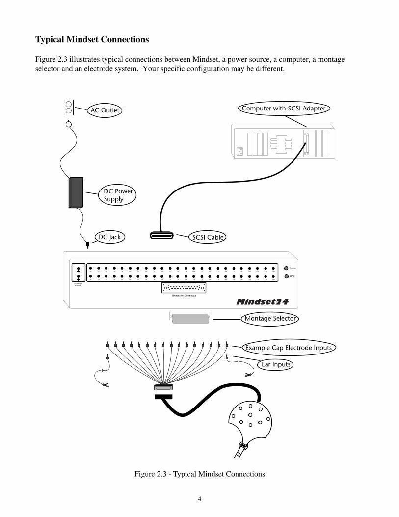
Typical Mindset Connections
Figure 2.3 illustrates typical connections between Mindset, a power source, a computer, a montageselector and an electrode system. Your specific configuration may be different.
Figure 2.3 - Typical Mindset Connections

5
Connecting Mindset to Your Computer
Step 1 - Position the Mindset24Find a level, flat, solid surface on which to place your unit. Place the unit away from sources of 60 Hzelectrical noise such as computer monitors, power supplies and florescent lighting to reduce the risk of60Hz contamination in your EEG data.
Step 2 - Connect the Power CablePower off all of your computer equipment and Mindset.
Turn off power to Mindset, to your computer and to all devices on the SCSI chain beforemaking any modifications to the SCSI bus.
Connect the power supply to the back of Mindset as previously illustrated. Plug the power supply’sthree-prong power plug into an appropriately grounded power receptacle, preferably with surge andspike protection.
Never operate Mindset in an ungrounded power outlet or in a power outlet shared with heavy-load equipment such as photocopiers, fans, air-conditioners, laser printers, or large computermonitors.
Step 3 - Connect the SCSI CableConnect the SCSI cable to your computer's SCSI port. Then connect the remaining 50-pin end to theback of Mindset in either the top or bottom 50-pin connector. These two connectors are functionallyidentical and the open connector can be used for adding more SCSI devices or for termination (more ontermination below).
Mindset amplifies EEG signals up to 32,000 times, so it is very sensitive to electrical noise.One potential source of noise is your computer’s SCSI bus. SCSI adapters (particularlyPCMCIA notebook SCSI adapters) and other SCSI devices may be a source of noise. Pleaserefer to Chapter 3: Achieving Good Recordings for more details.
SCSI devices are physically connected together by cables in a daisy chain. When we refer to first or lastdevices, we refer to the physical location of the device within the daisy chain rather than the SCSIidentification number (ID) of the device.
Figure 2.4 - SCSI Daisy Chain
Computer Middle Device Mindset24
Terminator
6
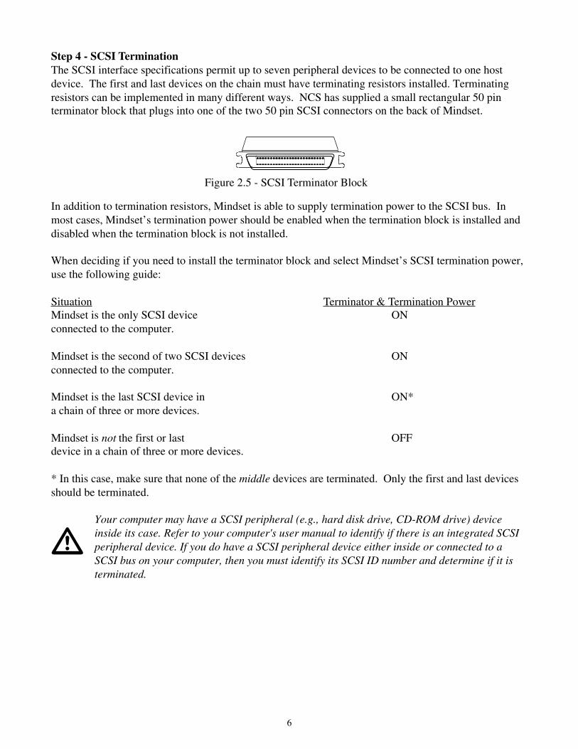
Step 4 - SCSI TerminationThe SCSI interface specifications permit up to seven peripheral devices to be connected to one hostdevice. The first and last devices on the chain must have terminating resistors installed. Terminatingresistors can be implemented in many different ways. NCS has supplied a small rectangular 50 pinterminator block that plugs into one of the two 50 pin SCSI connectors on the back of Mindset.
In addition to termination resistors, Mindset is able to supply termination power to the SCSI bus. Inmost cases, Mindset’s termination power should be enabled when the termination block is installed anddisabled when the termination block is not installed.
When deciding if you need to install the terminator block and select Mindset’s SCSI termination power,use the following guide:
Situation Terminator & Termination PowerMindset is the only SCSI device ONconnected to the computer.
Mindset is the second of two SCSI devices ONconnected to the computer.
Mindset is the last SCSI device in ON*a chain of three or more devices.
Mindset is not the first or last OFFdevice in a chain of three or more devices.
* In this case, make sure that none of the middle devices are terminated. Only the first and last devicesshould be terminated.
Your computer may have a SCSI peripheral (e.g., hard disk drive, CD-ROM drive) deviceinside its case. Refer to your computer's user manual to identify if there is an integrated SCSIperipheral device. If you do have a SCSI peripheral device either inside or connected to aSCSI bus on your computer, then you must identify its SCSI ID number and determine if it isterminated.
Figure 2.5 - SCSI Terminator Block
7
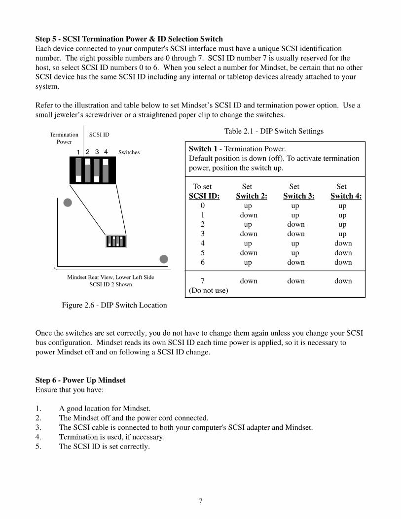
Step 5 - SCSI Termination Power & ID Selection SwitchEach device connected to your computer's SCSI interface must have a unique SCSI identificationnumber. The eight possible numbers are 0 through 7. SCSI ID number 7 is usually reserved for thehost, so select SCSI ID numbers 0 to 6. When you select a number for Mindset, be certain that no otherSCSI device has the same SCSI ID including any internal or tabletop devices already attached to yoursystem.
Refer to the illustration and table below to set Mindset’s SCSI ID and termination power option. Use asmall jeweler’s screwdriver or a straightened paper clip to change the switches.
Switch 1 - Termination Power.Default position is down (off). To activate terminationpower, position the switch up.
To set Set Set SetSCSI ID: Switch 2: Switch 3: Switch 4: 0 up up up 1 down up up 2 up down up 3 down down up 4 up up down 5 down up down 6 up down down
7 down down down(Do not use)
Mindset Rear View, Lower Left SideSCSI ID 2 Shown
Once the switches are set correctly, you do not have to change them again unless you change your SCSIbus configuration. Mindset reads its own SCSI ID each time power is applied, so it is necessary topower Mindset off and on following a SCSI ID change.
Step 6 - Power Up MindsetEnsure that you have:
1. A good location for Mindset.2. The Mindset off and the power cord connected.3. The SCSI cable is connected to both your computer's SCSI adapter and Mindset.4. Termination is used, if necessary.5. The SCSI ID is set correctly.
TerminationPower
SCSI ID Table 2.1 - DIP Switch Settings
Figure 2.6 - DIP Switch Location
1 2 3 4 Switches
8
Turn on Mindset’s power. Mindset's power switch is on the rear left side of the enclosure. The redpower light should come on and the yellow SCSI light should flash briefly.
It is a good idea to turn on all of the external SCSI devices before switching on your computer.
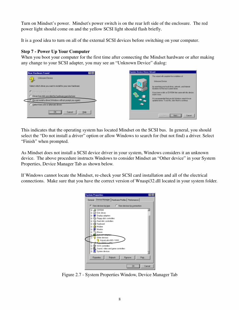
Step 7 - Power Up Your ComputerWhen you boot your computer for the first time after connecting the Mindset hardware or after makingany change to your SCSI adapter, you may see an “Unknown Device” dialog:
This indicates that the operating system has located Mindset on the SCSI bus. In general, you shouldselect the “Do not install a driver” option or allow Windows to search for (but not find) a driver. Select“Finish” when prompted.
As Mindset does not install a SCSI device driver in your system, Windows considers it an unknowndevice. The above procedure instructs Windows to consider Mindset an “Other device” in your SystemProperties, Device Manager Tab as shown below.
If Windows cannot locate the Mindset, re-check your SCSI card installation and all of the electricalconnections. Make sure that you have the correct version of Wnaspi32.dll located in your system folder.
Figure 2.7 - System Properties Window, Device Manager Tab

9
Electrode Configuration
Mindset is designed to accommodate any electrode system that has input leads which terminate in 1.5mm touch-proof safety connectors. If your input leads terminate in 2 mm tip plugs, adapters areavailable from most electrode system manufacturers and resellers who carry EEG supplies.
NCS accepts no liability for hazards which might arise from improper use of your electrodesystem. Exercise extreme care in handling all connections to human subjects, includingelectrodes and grounding straps. Follow all guidelines provided by the manufacturer of yourelectrode system. If you are unsure about any connection to a human subject, stop and seekproper guidance. Do not attempt to defeat any safety measures which may be integral to yourelectrode system. Do not construe the instructions in this manual to suggest practices thatmay allow any part of the electrode assembly to come into contact with a source of dangerouselectrical potential while a subject is connected.
Connection between EEG leads and ear clip leads to Mindset is accomplished through the front panel, asshown below:
Figure 2.8 - Mindset24 Front Panel, Electrode Input Section
All 24 Mindset EEG channel amplifiers have an “a” and “b” input. These are differential inputs. Eachchannel amplifies the difference between signals applied to its “a” and “b” inputs to create the finaldifferential signal which is digitized and sent to your computer. In this way, a signal common to bothinputs is rejected (e.g., ambient 60 Hz).
Please consult another source for general information on EEG systems design, common-moderejection and other general aspects of EEG signal amplification.
Expansion Connector
1b 2b 3b 4b 5b 6b 7b 8b 9b 10b 11b 12b 13b 14b 15b 16b
1a 2a 3a 4a 5a 6a 7a 8a 9a 10a 11a 12a 13a 14a 15a 16a
17b 18b 19b 20b 21b 22b 23b 24b
17a 18a 19a 20a 21a 22a 23a 24a

10
The international 10-20 standard for electrode placement is illustrated in Figure 2.9.
Figure 2.9 - International 10-20 Standard
If channel 1a is connected to Fp1 and channel 1b is connected to Fp2, the signal sent to your computeron channel 1 would be the difference between Fp1 and Fp2. This is represented in EEG nomenclature asCh 1 = Fp1-Fp2.
One standard configuration (or montage) for EEG neuromapping is known as linked-ear referential.This is Mindset’s default neuromapping montage. In a linked-ear referential montage, all channels’ “b”inputs are connected to ear clip positions A1+A2. This is accomplished by connecting one of theincluded montage selectors to the expansion connector on the Mindset front panel. Doing so ties eachchannel’s “b” inputs together. By inserting the input jacks from your electrode system’s ear clip leadsinto any two “b” inputs, you tie every channel’s “b” input to A1+A2.
If your electrode system utilizes mastoid references, simply connect the input jacks from thoseleads into any two “b” inputs when the montage selector is in place.
If you are using an Electro-Cap with Mindset, refer to Appendix IV for additional information.
Fp2
F8
A2
T4
T6
O2
P4
C4
F4
Cz
Fz
Pz
A1
T3
T5
O1
P3
C3
F3
Fp1
F7
Gnd

11
Channel “a” input “b” input
The default neuromapping connection between Mindset’s input channels and the 10-20 standardelectrode positions is as follows:
This default connection table is provided for convenience only. Mindset24 has 24 channels, so whenusing the 10-20 standard, 5 of Mindset’s channels are unconnected. You may chose to connect any ofthe 10-20 electrode positions to any Mindset input channel. If you differ from this default, however, youmust instruct the Mindset software that you have done so (this is covered in the software referencemanual).
Mindset does not provide an accessible point to connect to earth ground. If you intend to use yourelectrode system’s grounding point, you have to connect this lead to earth ground. Remember to followall guidelines provided by the manufacturer of your electrode system. If you are unsure about anyconnection to a human subject stop and seek proper guidance. See Chapter 3: Achieving GoodRecordings for additional information on human subject earth grounding.
Never connect a human subject to an earth ground unless you are absolutely certain that theconnection point is at earth ground potential! If you do connect a human subject to earthground, through whatever means, you must assure that the subject does not come in contactwith any source of electrical potential. Failure to comply with these warnings can expose thehuman subject to harmful and even fatal electrical current!
Electrode Impedance Checking
The electrode impedance should be minimized in accordance with instructions provided with yourspecific electrode system. Use of an electrode impedance meter ensures that each electrode is makingproper contact with the subject’s skin.
Table 2.2 - Standard 10-20 Electrode Positions
12345678910111213141516171819
Fp1Fp2F7F3FzF4F8T3C3CzC4T4T5P3PzP4T6O1O2
A1+A2A1+A2A1+A2A1+A2A1+A2A1+A2A1+A2A1+A2A1+A2A1+A2A1+A2A1+A2A1+A2A1+A2A1+A2A1+A2A1+A2A1+A2A1+A2

12
Chapter 3: Achieving Good Recordings
You must refer to other sources for general EEG information, description of proper EEG recordingtechniques, and for detailed discussion of EEG artifacts. A general knowledge of EEG is essential toobtaining valid data. Please read the Electrode Configuration paragraphs of Chapter 2 before attemptingEEG recording.
Techniques to Obtain the Best EEG Recordings with Mindset
Follow these steps to obtain the best EEG recordings when using Mindset:
1. Assure proper electrode impedance values for your electrode system.
2. Restrict movement of the subject while recording. Using a rolled towel to support thesubject’s neck will minimize head movement.
3. Watch the maximum amplitude of the input signal. If the amplitude exceeds 120 microvolts (uV)peak-to-peak, the amplifiers will saturate and the resultant data is clipped and invalid as shown in Figure3.1.
If you need to extend Mindset’s amplitude range, contact your distributor about the customgain ranges.
Figure 3.1 - Amplifier Saturation
13
Minimizing Artifact Data Contamination
EEG data must be free of artifacts for meaningful analysis to be possible. It is vitally important that youtake careful steps to minimize artifacts before recording.
This section of the manual addresses specific steps which may be taken to reduce or eliminate commonsources of artifacts when using Mindset. Each type of artifact described below may occur in one, agroup, or all of the Mindset channels.
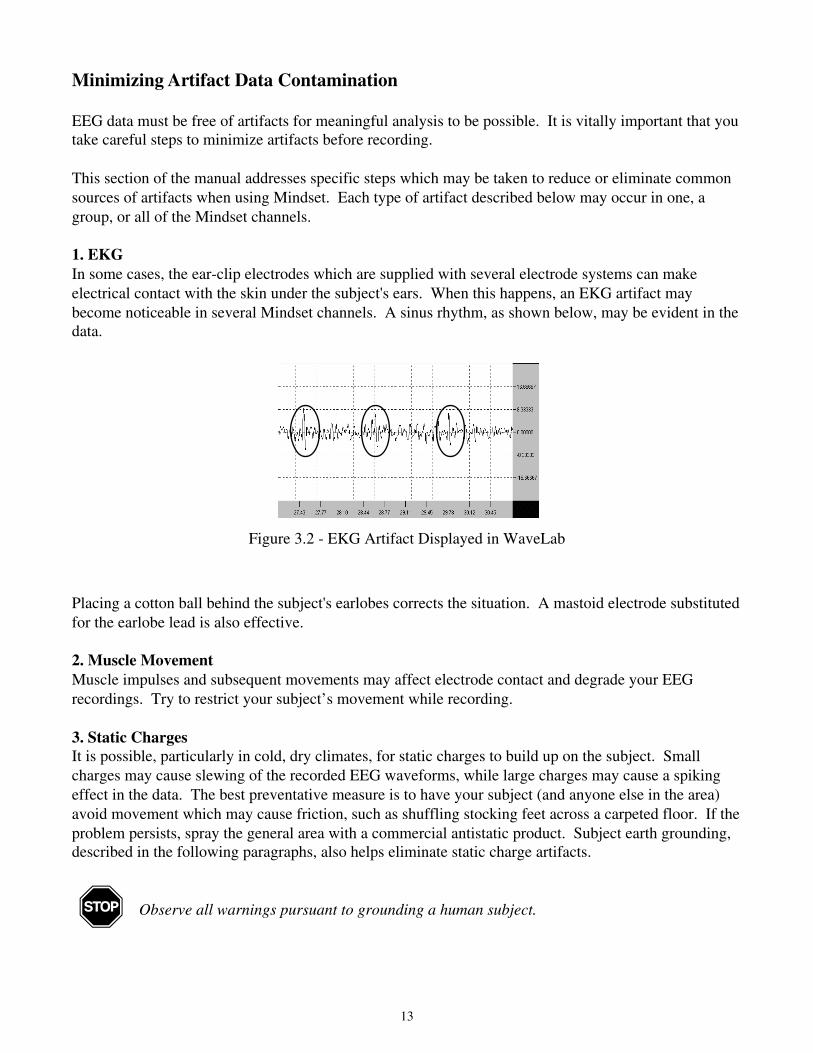
1. EKGIn some cases, the ear-clip electrodes which are supplied with several electrode systems can makeelectrical contact with the skin under the subject's ears. When this happens, an EKG artifact maybecome noticeable in several Mindset channels. A sinus rhythm, as shown below, may be evident in thedata.
Placing a cotton ball behind the subject's earlobes corrects the situation. A mastoid electrode substitutedfor the earlobe lead is also effective.
2. Muscle MovementMuscle impulses and subsequent movements may affect electrode contact and degrade your EEGrecordings. Try to restrict your subject’s movement while recording.
3. Static ChargesIt is possible, particularly in cold, dry climates, for static charges to build up on the subject. Smallcharges may cause slewing of the recorded EEG waveforms, while large charges may cause a spikingeffect in the data. The best preventative measure is to have your subject (and anyone else in the area)avoid movement which may cause friction, such as shuffling stocking feet across a carpeted floor. If theproblem persists, spray the general area with a commercial antistatic product. Subject earth grounding,described in the following paragraphs, also helps eliminate static charge artifacts.
Observe all warnings pursuant to grounding a human subject.
Figure 3.2 - EKG Artifact Displayed in WaveLab
14
Electrical Noise Considerations
Since Mindset amplifies EEG signals up to 32,000 times, it is very sensitive to electrical noise. Whilecareful design measures were taken to isolate Mindset from ambient noise, it is possible in extremecircumstances that electrical noise may contaminate the EEG data. In almost every case, making minorchanges in your SCSI configuration, reorienting Mindset’s power supply connection to AC, orconnecting your subject to a solid earth ground should remedy the contamination.
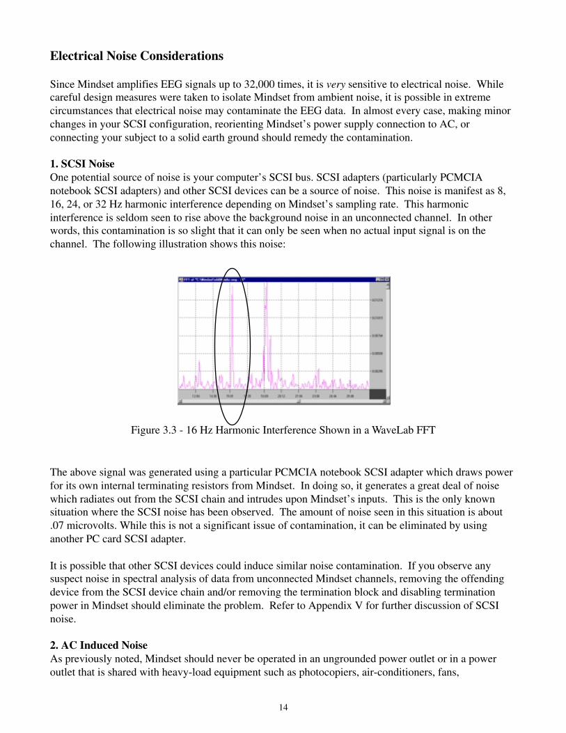
1. SCSI NoiseOne potential source of noise is your computer’s SCSI bus. SCSI adapters (particularly PCMCIAnotebook SCSI adapters) and other SCSI devices can be a source of noise. This noise is manifest as 8,16, 24, or 32 Hz harmonic interference depending on Mindset’s sampling rate. This harmonicinterference is seldom seen to rise above the background noise in an unconnected channel. In otherwords, this contamination is so slight that it can only be seen when no actual input signal is on thechannel. The following illustration shows this noise:
The above signal was generated using a particular PCMCIA notebook SCSI adapter which draws powerfor its own internal terminating resistors from Mindset. In doing so, it generates a great deal of noisewhich radiates out from the SCSI chain and intrudes upon Mindset’s inputs. This is the only knownsituation where the SCSI noise has been observed. The amount of noise seen in this situation is about.07 microvolts. While this is not a significant issue of contamination, it can be eliminated by usinganother PC card SCSI adapter.
It is possible that other SCSI devices could induce similar noise contamination. If you observe anysuspect noise in spectral analysis of data from unconnected Mindset channels, removing the offendingdevice from the SCSI device chain and/or removing the termination block and disabling terminationpower in Mindset should eliminate the problem. Refer to Appendix V for further discussion of SCSInoise.
2. AC Induced NoiseAs previously noted, Mindset should never be operated in an ungrounded power outlet or in a poweroutlet that is shared with heavy-load equipment such as photocopiers, air-conditioners, fans,
Figure 3.3 - 16 Hz Harmonic Interference Shown in a WaveLab FFT

15
laser printers, or large computer monitors. Such devices can cause glitches in a building’s entire powerdistribution system and affect EEG data even if Mindset is not sharing a power outlet with them.Filtered power strips (line filters) with surge and spike protection can help prevent these transientglitches from appearing in your data. If you detect consistent spiking glitches in the waveform datafrom Mindset, it may be necessary to connect Mindset’s power supply to another leg of your building’smain power transformer. However, this measure is rarely called for.
3. Subject Earth Ground - 50 or 60 Hz Induced NoiseIn environments with high levels of 60 Hz (or 50 Hz) electrical noise emanating from florescent lightingfixtures, laboratory equipment, computer equipment, or other noisy equipment, the levels of 60 Hzriding on your subject’s body may exceed Mindset’s high levels of 60 Hz filtration. Figure 3.4illustrates 60 Hz contamination in a Mindset channel.
Figure 3.4 - 60Hz Noise Shown in a WaveLab FFT
In this situation, it may become necessary to connect your subject to earth ground using an appropriategrounding strap or grounding point provided by your electrode system. This should bleed off the 60 Hznoise.
Mindset does not provide an accessible point to connect to earth ground. If you intend to useyour electrode system’s grounding point, you have to connect this lead to earth ground.Remember to follow all guidelines provided by the manufacturer of your electrode system. Ifyou are unsure about any connection to a human subject, stop and seek proper guidance.
Never connect a human subject to an earth ground unless you are absolutely certain that theconnection point is at earth ground potential! If you do connect a human subject to earthground, through whatever means, you must assure that the subject does not come in contactwith any source of electrical potential. Failure to comply with these warnings can expose thehuman subject to harmful and even fatal electrical current!

16
Appendix I - Support and Service
Customer SupportThe best source of Mindset support is your distributor. Technical questions and issues may also be e-mailed to [email protected]. Please consult this manual before calling for technicalsupport.
Developer SupportNCS is committed to supporting developers and end-users who wish to add functionality or createcustom applications for Mindset. Please contact Wayne Nolan, Nolan Computer Systems, L.L.C. [email protected] for more information.
Product ServiceShould your Mindset24 require service, contact [email protected] for returnauthorization.
Electrode systems are warranted through their original manufacturer. Contact your electrode systemmanufacturer with any questions or service requirements specific to their products.
Mindset is warranted to be free from defects which effect proper operation for aperiod of one year from the date of sale. Units returned for in-warranty servicemust be accompanied by a copy of the bill-of-sale. Please refer to the Mindset24Limited Hardware Warranty (on page 17) for more information.

17
MINDSET LIMITED HARDWARE WARRANTY
Nolan Computer Systems, L.L.C. (NCS) warrants the MINDSET hardware against defects in material or workmanship asfollows:
1. Labor: For a period of one (1) year from the original date of purchase from NCS or its distributors, NCS will repair defectsin MINDSET at no charge or pay the labor charges to any NCS authorized service facility. After this 1 year period, you mustpay for all labor charges.
2. Parts: For a period of one (1) year from the original date of purchase from NCS or its distributor, NCS will supply, at nocharge, new or rebuilt replacement parts (at its discretion) in exchange for defective parts of MINDSET. Any replacementparts will be warranted for the remainder of the original warranty period or ninety (90) days from installation by NCS’sauthorized service facility, whichever is longer. All exchanged parts replaced under this warranty will become the property ofNCS.
This warranty extends only to the original purchaser. It is not transferable to anyone who subsequently purchases aMINDSET from you.
Proof of purchase in the form of a copy of the bill-of-sale (which is evidence that MINDSET is within the warranty period)must be presented to obtain warranty service.
Be sure to remove all features, parts, options, alterations, and attachments not under warranty prior to returning MINDSET toNCS. NCS is not liable for any loss or damage to these items.
This Limited Warranty does not cover any consumable items supplied with MINDSET, cosmetic damages, damage or loss toany software programs, data, or removable storage media, or damage due to:
1. acts of nature, accident, misuse, abuse, negligence, commercial use or modifications of MINDSET2. improper operation or maintenance of MINDSET3. connection to improper voltage supply4. attempted repair by any party other than an NCS authorized service facility.
This Limited Warranty does not apply when the malfunction results from the use of MINDSET in conjunction with accesso-ries, products, or ancillary or peripheral equipment, or where it is determined by NCS that there is no fault with MINDSETitself.
This Limited Warranty is invalid if the factory applied serial number has been altered or removed from MINDSET.
REPAIR OR REPLACEMENT AS PROVIDED UNDER THIS WARRANTY IS THE EXCLUSIVE REMEDY OF THECONSUMER. NCS SHALL NOT BE LIABLE FOR ANY INCIDENTAL OR CONSEQUENTIAL DAMAGES FORBREACH OF ANY EXPRESS OR IMPLIED WARRANTY, BREACH OF CONTRACT NEGLIGENCE, STRICT LIABIL-ITY OR ANY OTHER LEGAL THEORY RELATED TO MINDSET. SUCH DAMAGES INCLUDE, BUT ARE NOTLIMITED TO, LOSS OF PROFITS, LOSS OF REVENUE, LOSS OF DATA, LOSS OF USE OF MINDSET OR ANYASSOCIATED EQUIPMENT, DOWN TIME AND PURCHASER’S TIME. EXCEPT TO THE EXTENT PROHIBITED BYAPPLICABLE LAW, ANY IMPLIED WARRANTY OF MERCHANTABILITY OR FITNESS FOR A PARTICULARPURPOSE ON MINDSET IS LIMITED IN DURATION TO THE DURATION OF THIS WARRANTY.
Some states do not allow the exclusion or limitation of incidental or consequential damages, or allow limitations on how longan implied warranty lasts, so the above limitations or exclusions may not apply to you. This warranty gives you specific legalrights and you may have other rights which vary from state to state.

18
Appendix II - Cleaning Mindset
Turn off and unplug Mindset before cleaning.Do not spill liquid on Mindset. Do not under any circumstances allow liquid to touch theinput jacks or the expansion connector.
The Mindset24 enclosure should be cleaned with a water-dampened cloth only.
If any evidence of corrosion is evident in the front input jacks or expansion connector, they may becleaned only with a commercial electronic contact cleaner. Follow the guidelines provided with thecommercial product.

19
Appendix III - Mindset24 Specifications
Specifications are typical and are subject to change without notice.
1. Channels24 differential input channels (48 input jacks)90 dB amplifier gain, 60dB signal to noise ratio
2. Resolution16 bit analog to digital converter64 to 512 samples/second/channel
3. FiltrationTwo fourth-order Sallen-Key active filters, 48 dB roll-off per octave1.5 Hz - 34 Hz frequency pass band @ -3 dB (0.9 Hz - 38 Hz @ -6 dB)
4. Common Mode Rejection120 dB maximum, 87 dB typical in pass band
5. Input Range0 - 120 microvolts (µV) peak-to-peak
6. ElectrodesStandard electrode inputs (compatible with Electro-Cap and e-Net)
7. Montage Reference ConfigurationUser selectable through expansion connectorLinked-Ear to B-Inputs Referential montage selectors supplied
1.5 Hz 34 Hz
Pass Band

20
Two SCSI (Standard Centronics-type connectors)
8. Expansion Connector Pinout
9. Interface to Computer
24b
23b
22b
21b
20b
19b
18b
17b
16b
15b
14b
13b
12b
nc
nc
nc
11b
nc
10b
nc
9b
nc
nc
nc
nc
nc
7b
8b
5b
6b
3b
4b
1b
2b
Mindset Expansion Connector Pinout, Front View. Female DB-37Pin # 1 on Mindset Connector
Denotes Mindset Channel 22, Input b
Pin # 37 on Mindset Connector
nc

21
10. Opto-Isolation2500 volts RMS
11. Total Harmonic Distortion-87 dB.01% opto-isolator servo linearity
12. CalibrationFactory calibrated*, automatic and user calibration via software(*optional calibration certificate available)
13. PowerInput Voltage: 90 - 264 VACAC Input Frequency: 47 - 63 HzSwitching Frequency: 50,000 Hz (typical)Power Consumption: 15 watts
14. Operational Temperature32º F - 90º F, do not operate in direct sunlight
15. Dimensions and Weight13” deep, 17” wide, 3.9” highMain unit - 8 pounds, external power supply - 8.3 ounces
22
Appendix IV - Electro-Cap Users
NCS accepts no liability for hazards which might arise from improper use of your electrodesystem. Exercise extreme care in handling all connections to human subjects, includingelectrodes and grounding straps. Follow all guidelines provided by the manufacturer of yourelectrode system. If you are unsure about any connection to a human subject, stop and seekproper guidance. Do not attempt to defeat any safety measures which may be integral to yourelectrode system. Do not construe the instructions in this manual to suggest practices that mayallow any part of the electrode assembly to come into contact with a source of dangerouselectrical potential while a human subject is connected.
Additional Information for Electro-Cap Procedures
Complete all steps as specified in the Electro-Cap manual for attaching the body harness, attaching thecap, and preparing the electrode sites. Refer to the following illustrations as an aid in connecting theElectro-Cap to the Mindset.
Your Electro-Cap Electrode Board Adapter wires may need to be separated two inches furtherin order for all pins to reach the Mindset24 input jacks without tension. Separate the wirescarefully and evenly. The wires should never, under any circumstances, be separated all theway back to the connector.

23
Green - R
ed
Green - W
hite
Gray - R
ed
Yellow
- Red
Yellow
- White
Gray - W
hite
Violet - R
ed
Orange - R
ed
Red - W
hite
Blue - W
hite
Brow
n - Red
Brow
n - White
Orange - W
hite
Violet - W
hite
Blue - R
ed
Red - R
ed
Ear C
lip Lead
Ear C
lip Lead
Mindset Standard Neuromapping Montage Wiring, 19 Channels
Electrode Site:
Electrode BoardAdapter Wire:
Electrode BoardAdapter Tip:
A1 or 2* A2 or 1*
Fp2
F8
A2
T4
T6
O2
P4
C4
F4
Cz
Fz
Pz
A1
T3
T5
O1
P3
C3
F3
Fp1
F7
Gnd
Electro-Cap Pinout
White Wire RedTip Color Tip
Fp1 Brown Fp2F3 Red F4C3 Orange C4P3 Yellow P4O1 Green O2F7 Blue F8T3 Violet T4T5 Gray T6Gnd White CzFz Black Pz
Expansion Connector
1b 2b 3b 4b 5b 6b 7b 8b 9b 10b 11b 12b 13b 14b 15b 16b
1a 2a 3a 4a 5a 6a 7a 8a 9a 10a 11a 12a 13a 14a 15a 16a
17b 18b 19b 20b 21b 22b 23b 24b
17a 18a 19a 20a 21a 22a 23a 24a
Fp1 Fp2 F7 F3 Fz F4 F8 T3 C3 Cz C4 T4 T5 P3 Pz P4 T6 O1 O2
Black - W
hite
White - R
ed
Black - R
ed
Montage Selector
Linked Ear B Inputs
If your cap has additional electrodes for additional channels, you may use them in Mindset24 channels20 - 24 in any order you wish. Simply set the channel labels in the software (refer to the Mindset24Software Reference Manual) to correspond to the electrode locations.
* With the Linked-Ear to B Inputs montage selector in place, the A1 and A2 reference leads may be inserted into any of the channel “b”inputs. The montage selector shorts each of the channels “b” inputs together. If a 19 channel montage selector is used, only channel 1 to 19“b” inputs are shorted together. This keeps unused channels 20 to 24 quiet when performing a standard 10-20 montage.

24
Subject Earth GroundMindset does not provide an accessible point to connect to earth ground. If you intend to use yourElectro-Cap's grounding point (Gnd), you must connect this lead to earth ground.
Never connect a human subject to an earth ground unless you are absolutely certain that theconnection point is at earth ground potential! If you are unsure about any connection to ahuman subject, stop and seek proper guidance. If you do connect a human subject to earthground, through whatever means, you must assure that the subject does not come in contactwith any source of electrical potential. Failure to comply with these warnings can expose thehuman subject to harmful and even fatal electrical current!
See Chapter 3: Achieving Good Recordings for additional information the on topic of earth grounding.
Impedance CheckingThe electrode impedance should be minimized in accordance with instructions provided with yourspecific electrode system. Use of an electrode impedance meter ensures that each electrode is makingproper contact with the patient’s skin.
EKG ArtifactIn some cases, the supplied ear-clip electrodes can make electrical contact with the skin under thesubject's ears. When this happens, an EKG artifact may become noticeable in several Mindset channels.Placing a cotton ball behind the patient’s earlobes after applying the Electro-Cap should correct thesituation.

25
Appendix V - Additional SCSI Issues
Background
A SCSI bus is a resistor terminated, high current bus. The termination resistors (or block) do two things:
• help match the characteristic impedence of the SCSI bus wires to the input circuitry,thus preventing the signals from reflecting and ringing.
• termination power is applied through the resistors to pull the voltage on the wires upto at least 2.8 volts.
A high (2.8 to 5.0) voltage on the bus wires represents the inactive or zero state. A signal is drivenactive by driving the voltage to below 0.7 volts.
Without termination power, all of the wires on the bus would remain at zero volts and no communicationwould be possible. Without termination resistors, signals on the bus are not at their proper voltages andcan cause ringing and unreliable operation. Therefore, both termination power and termination resistorsare necessary. Most SCSI devices are designed to provide termination power, including Mindset.
Unfortunately, high current on the SCSI bus leads to strong magnetic fields being generated. Thesemagnetic fields in turn create voltages in wires that they cross. Mindset’s amplifiers are very sensitiveand can pick up these minute signals. The goal is to minimize these signals.
Noise Intrusion
Depending upon several factors (such as; sample rate, SCSI bus termination, SCSI bus configuration,etc.) it is possible for SCSI bus noise to intrude upon EEG data. This noise usually shows up as aspurious 2, 4, 8, 16 or 32 Hz signal. This is because MindMeld may be transferring data from theMindset hardware at these frequencies and the SCSI bus has heavy activity.
The noise is best seen by taking a minute or two of data without any connections to Mindset’s frontpanel. If you observe such noise, try setting the SCSI block size to a smaller value (refer to theMindset24 Software Reference Manual for instructions). This forces MindMeld to access Mindset at ahigher rate because the same amount of data will be transferred each second. The objective is to makethis access rate higher than 32 Hz, moving it out of Mindset’s passband.
For example, assume you are sampling at 256 sps and the SCSI block transfer size is set to 768 bytes.Every second there are 12,288 bytes of data transferred across the SCSI bus:
256 samples/second x 2 bytes/sample x 24 channels = 12,288 bytes/second.
Since MindMeld grabs these data in 768 byte blocks (the SCSI block size), the access frequency fromMindMeld to Mindset is 12,288 / 768 = 16 accesses per second. Under some circumstances this mayshow up as a spurious 16 Hz signal in the EEG data.

26
Mindset is the only device on the SCSI bus and:
• The host computer is providing termination power, Mindset’s termination power is off and termination block removed.
• The host computer is providing termination power, Mindset’s termination block is in place.
• Mindset’s termination power is on, Mindset’s termination block is removed.
• Mindset’s termination power is on, Mindset’s termination block is in place.
Mindset is one of several SCSI devices connect to the bus and:
• The host computer is providing termination power, Mindset’s termination power is off and termination block is removed.
• The host computer is providing termination power, Mindset’s termination block is in place.
• Mindset’s termination power is on, Mindset’s termination block is removed.
• Mindset’s termination power is on, Mindset’s termination block is in place.
More Quiet
More Noisy
In most cases, if Mindset is the only device on the SCSI bus and the host computer is providing termina-tion power, Mindset runs fine with its own termination power and termination block off. This configura-tion results in the least amount of noise intrusion.
For power conservation, some laptop computer SCSI cards do not provide termination power. Refer tothe manual provided with your SCSI card. If possible, turn on the SCSI card’s termination power andturn Mindset’s off. If your card does not provide termination power, you must turn on Mindset’s. Youmay have to experiment with various configurations to obtain the quietest and most reliable operation.
In this example, if you were to reset the block size to 384 bytes, the access rate would be forced todouble to 32 accesses per second, thus moving the undesired signal to the upper end of the passband.
With some SCSI cards the noise is more pronounced. In general, if a SCSI card draws its terminationpower from Mindset, the noise is more likely to show up. It is always best to use Mindset as the onlydevice on the SCSI bus chain. The SCSI card in your PC should be supplying the termination power. Ifthis is the case, you can turn Mindset’s termination power off and remove the termination block.
Below is a list of possible SCSI configurations. They are listed in order, from most quiet to most noisy.
Table E.1 - SCSI Configurations vs Noise Levels