LINCOLNassets.lincolnelectric.com/assets/EU/OperatorManuals/IM...them to prevent the welding sparks...
32
LINCOLN ELECTRIC R OPERATING MANUAL OF THE WELDING SEMI-AUTOMATIC Compact 185 EN ISO 9001 CERT CERT TUV TUV ..
Transcript of LINCOLNassets.lincolnelectric.com/assets/EU/OperatorManuals/IM...them to prevent the welding sparks...

LINCOLNELECTRIC
R
OPERATING MANUAL OF THE WELDING SEMI-AUTOMATIC
Compact 185EN ISO 9001
CERTCERTTUVTUV..

BESTER S.A. ul. Jana III Sobieskiego 19A, 58-260 Bielawa, Poland
and has been designed in conformance with the following norms:und in Übereinstimmung mit den nachstehenden Normen hergestellt wurde:i ¿e zosta³o zaprojektowane zgodnie z wymaganiami nastêpuj¹cych norm:
73/23/CEE, 93/68/CEE, 89/366/CEE, 92/31/CEE
conforms to the following directives:dan folgenden Bestimmungen entspricht:
spe³nia nastêpuj¹ce wytyczne:
Compact 185 s/n
Declares that the welding machine:Erklärt, daß die Bauart der Maschine:
Deklaruje, ¿e spawalnicze Ÿród³o energii:
Thank You
Declaration of confirmityKonformitätserklärungDeklaracja zgodnoœci
BESTER S.A.
EN 50199, EN 60974-1
for selecting a QUALITY product by Lincoln Electric.We want you to take pride in operating thisLincoln Electric Co. product Compact 185 as muchpride as we have in briging this product to you!
Pawe³ LipiñskiOperational Director
Table of Contents
Safety
Features
4
10
11
12
13
14
16
16
16
17
19
18
20
15
21
22
21
23
30
29
24
25
32
General Information and Warning
Front Panel of the Compact 185
Rear Panel of the Compact 185
Trouble Shooting Guide
Preparation for Welding Works
Environmental Conditions
Information about the Producer
Connecting Shielding Gas
Inserting Electrode Wire and Braking Torque Adjustment
Technical Data
Care and maintenance
Storage and Transportation
Static Characteristics of the Compact 185
Spot Welding
Defects of Welding Seams
Plugging Compact 185 in
Installation of the Compact 185
Spare Parts List
Notes
Assembly of the Drive Roll of the Feeding Unit
Welding Parameters
Page 3

Safety
Warning!
Protect yourself and others from possible serious injury or death.
Keep children away. Pacemaker wearers should consult with
- In addition to the normal safety precautions, if welding must be per-
their doctor before operating.
Pay attention in handling the pieces being worked on, use ade-
quate tools to avoid burns can be caused by the overheating of
the piece during the operation of welding and/or cutting.
Be sure that all installation, maintenance, and repair procedures
are performed only by qualified individuals.
ELECTRIC SHOCK can ki l l
- The electrode and work /or ground/ circuits are electrically "hot" when the
welder is on. Do not touch these "hot" parts with your bare skin or wet
clothing. Wear dry, hole-free gloves to insulate hands.
- Insulate yourself from work and ground using dry insulation. Make sure
the insulation is large enough to cover your full area of physical contact
with work and ground.
formed under electrically hazardous conditions /in damp locations or
while wearing wet clothing; on metal structures such as floors, gra-
tings or scaffolds; when in cramped positions such as sitting, knee-
ling or lying, if there is a high risk of unavoidable or accidental contact
with the workpiece or ground/ use the following equipment:
* Semiautomatic DC Constant Voltage Wire/ Welder
* DC Manual /Stick/ Welder
* AC Welder with Reduced Voltage Control
- In semiautomatic or automatic wire welding, the electrode, electrode reel,
welding head, nozzle or semiautomatic welding gun are also electrical "hot".
- Always be sure the work cable makes a good electrical connection with
the metal being welded. The connection should be as close as possible
to the area being welded.
Page 4

ARC RAYS can burn
FUMES AND GASES can be dangerous
- Ground the work or metal to be welded to a good electrical /earth/ ground.
- Maintain the electrode holder, work clamp, welding cable and welding ma-
chine in good, safe operating condition. Replace damaged insulation.
- Never dip the electrode in water for cooling.
- Never simultaneously touch electrically "hot" parts of electrode holders
connected to two welders because voltage between the two can be the
total of the open circuit voltage of both welders.
- When working above floor level, use a safety belt to protect yourself from
a fall should you get a shock.
- Use a shield with the proper filter and cover plates to protect your eyes
from sparks and the rays of the arc when welding or observing open arc
welding. Headshield and filter lens should conform to ANSI Z87. I stan-
dards.
- Use suitable clothing made from durable flame-resistant material to pro-
tect your skin and that of your helpers from the arc rays.
- Protect other nearby personnel with suitable non-flammable screening
and/or warn them to watch the arc nor expose themselves to the arc rays
or to hot spatter or metal.
- Welding may produce fumes and gases hazardous to health. Avoid brea-
thing these fumes and gases. When welding, keep your head out of the
fume. Use enough ventilation and/or exhaust at the arc to keep fumes
and gases away from the breathing zone. When welding with electrodes
which require special ventilation such as stainless or hard facing or on
lead or cadmium plated steel and other metals or caotings which produce
highly toxic fumes, keep exposure as low as possible and below TLV
Page 5

WELDING SPARKS can cause f i re or explosion
/Threshold Limit Values/ using local exhaust or mechanical ventilation.
In confined spaces or in some circumstance, outdoors, a respirator may
be required. Additional precautions are also required when welding on
galvanized steel.
- Do not weld in locations near chlorinated hydrocabron vapors coming from
degreasing, cleaning or spraying operations. The heat and rays of the arc
can react with solvent vapors to form phosogne, a highly toxic gas, and
other irritating products.
- Shielding gases used for arc welding can displace air and cause injury or
death. Always use enough ventilation, especially in confined areas, to in-
sure breathing air is safe.
- Read and understand the manufacturer's instructions for this equipment
and the consumables to be used, including the material safety data sheet
and follow your employer's safety practices.
- Remove fire hazards from the welding area. If this is not possible, cover
them to prevent the welding sparks from starting a fire. Remember that
welding sparks and hot materials from welding can easily go through
small cracks and openings to adjacent areas. Avoid welding near hydraulic
lines. Have a fire extinguisher readily available.
- Where compressed gases are to be used at the job site, special precau-
tions should be used to prevent hazardous situations.
- When not welding, make certain no part of the electrode circuit is touch-
ing the work or ground. Accidental contact can cause overheating and
create a fire hazard.
- Do not heat, cut or weld tanks, drums or containers until the proper steps
have been taken to insure that such procedures will not cause flammable
or toxic vapors from substances inside.
Page 6

CYLINDER may explode i f damaged
They can cause an explosion even though they have been "cleaned".
For information purchase "Recommended Safe Practices for the Prepa-
ration for Welding and Cuttig of Containers and Piping That Have Held
Hazardous Substances", AWS F4.1 from the American Welding Society.
- Vent hollow castings or containers before heating, cutting or welding.
They may explode.
- Sparks and spatter are thrown from the welding arc. Wear oil free prote-
ctive garments such as leather gloves, heavy shirt, cuffless trousers, high
shoes and a cap over your hair. Wear ear plugs when welding out of po-
sition or in confined places. Always wear safety glasses with side shields
when in a welding area.
- Connect the work cable to the work as close to the welding area as pra-
ctical. Work cables connected to the building framework or other locations
away from the welding area increase the possibility of the welding current
passing through lifting chains, crane cables or other alternate circuits.
This can create fire hazards or overheat lifting chains or cables until they
fail.
- Use only compressed gas cylinders containing the correct shielding gas
for the process used and properly operating regulators designed for the
gas and pressure used. All hoses, fittings, etc. should be suitable for the
application and maintained in good condition.
- Always keep cylinders in an upright position securely chained to an under-
carriage or fixed support.
- Cylinders should be located:
* Away from areas where they may be struck or subjected to physical
damage.
* A safe distance from arc welding or cutting operations and any other
source of heat, sparks, or flame.
Page 7

FOR ELECTRICALLY powered equipment
- Never allow the electrode, electrode holder or any other electrically "hot"
parts to touch a cylinder.
- Keep your head and face away from the cylinder valve outlet when open-
ing the cylinder valve.
- Valve protection caps should always be in place and hand tight except
when the cylinder is in use or connected for use.
- Turn off input power using the disconnect switch at the fuse box before
working on the equipment.
- Install equipment in accordance with the U.S.National Electrical Code,
all local codes and the manufacturer's recommendations.
- Ground the equipment in accordance with the U.S. National Electrical
Code and the manufacturer's recommendations.
- Do not add the fuel near an open flame welding arc or when the engine
is running. Stop the engine and allow it to cool before refueling to prevent
spilled fuel from vaporizing on contact with hot engine parts and igniting.
Do not spill fuel when filling tank. If fuel is spilled, wipe it up and do not
start engine until fumes have been eliminated.
- Keep all equipment safety guards, covers and devices in position and in good
repair. Keep hands, hair, clothing and tools away from V-belts, gears, fans
and all other moving parts when starting, operating or repairing equipment.
Page 8

ELECTRIC AND MAGNETIC FIELDS may be dangerous
- In some cases it may be necessary to remove safety guards to perform
required maintenance. Remove guards only when necessary and repla-
ce them when the maintenace requiring their removal is complete. Always
use the greatest care when working near moving parts.
- Do not put your hands near the engine fan. Do not attempt to override
- To prevent accidentally starting gasoline engines while turning the engi-
ne or welding generator during maintenance work, disconnect the spark
the governor or idler by pushing on the throttle control rods while the
engine is running.
plug wires, distributor cap or magneto wire as appropriate.
- To avoid scalding, do not remove the radiator pressure cap when the
engine is hot.
- Electric current flowing through any conductor causes localized Electric
and Magnetic Fields /EMF/. Welding current creates EMF fields around
welding cables and welding machines.
- EMF fields may interfere with some pacemakers, and welders having
- Exposure to EMF fields in welding may have other health affects which
- To minimize exposure to EMF fields all welders should:
a pacemaker should consult their physician before welding.
are now not know.
* Route the electrode and work cables together .
* Do not place your body between the electrode and work cables.
* Never coil the electrode lead around your body.
* Connect the work cable to the workpiece as close as possible.
* Do not work next to welding power source.
Page 9

General Information and Warning
- Do not install, operate or repair this equipment without reading this
Manual and the safety precautions contained throughout. Save this
Manual and keep it handy for reference.
- Disconnect mains of the welding semi-automatic machine after finishing
work or before a longer break.
ration of using safety and they may expose users to electric shock.
use changes its features and deterioration of technical data.
- Do not make any own modifications of the Compact 185. It may ca-
user's fault causes loss guarantee rights.
- Any adaptations of this machine are prohibited and they cause not
only loss of the guarantee rights but they may be a cause of deterio-
- Any damage of the Compact 185 caused by improper use or through
- It is prohibited switching the semi-automatic machine on at short
ciruit of the welding cables.
- Acceptable range of ambient temperature is from - 10 to + 40 C.
- Acceptable humidity is up to 90 % at t = 20 C.
- Producer reserves the right to change specifications without pre-
vious notice.
Page 10
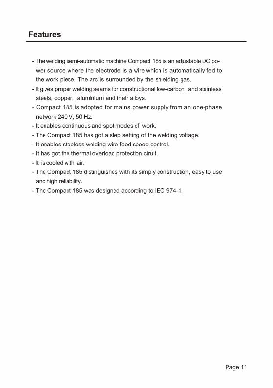
Features
- The welding semi-automatic machine Compact 185 is an adjustable DC po-
wer source where the electrode is a wire which is automatically fed to
the work piece. The arc is surrounded by the shielding gas.
network 240 V, 50 Hz.
- The Compact 185 has got a step setting of the welding voltage.
steels, copper, aluminium and their alloys.
- It enables continuous and spot modes of work.
- It gives proper welding seams for constructional low-carbon and stainless
- It is cooled with air.
- The Compact 185 distinguishes with its simply construction, easy to use
- The Compact 185 was designed according to IEC 974-1.
and high reliability.
- It enables stepless welding wire feed speed control.
- Compact 185 is adopted for mains power supply from an one-phase
- It has got the thermal overload protection ciruit.
Page 11

Rated Mains Voltage 240 V AC , 50 Hz
Power Consumption at Duty Cycle 15%
Input Current at Duty Cycle 15%
at Duty Cycle 15 % at Duty Cycle 60 % at Duty Cycle 100 %
Welding Current / Apparent Working Voltage:
Open Circuit Voltage
Welding Current Range
6.2 kVA
+7%-10%
26 A
180A / 23V100A / 19V70A / 17.5V
21 - 37 V
35 - 180 A
Electrode Wire Feed Speed
Electrode Wire Diameter
1 - 14 m/min
0.6 - 1.0 mm
Weight /without Cables/
Degree of Protection
Insulation Class
Dimensions /WxHXD/
IP21
H
60 kg
420x650x800 mm
Power Factor cos at Rated Load
Number of Welding Voltage Steps
0.93
6
3 m
2 m
4 m
Technical Data
Basic Equipment:- Ground Cable with the Work Clamp
- Shielding Gas Hose
- Mains Cable without the Plug
- welding torch with the welding cable
Page 12

01
354
26
COMPACT 185
LINCOLNELECTRIC
R
CES
V
1
2
3 5
64
6
4
5
3
Warning! It is not allowed changing the welding voltage
range during welding process!
ground welding cable
2
1
"Euro" socket for connecting the welding torch
knob of the electrode wire feed speed control
thermal protection idicator
power supply indicator
Front Panel of the Compact 185
selector: switch power supply off / change of the welding vol-
tage range
12
3
4
56
78
9
10
11
Page 13

ZAK£ADY URZ¥DZEÑ TECHNOLOGICZNYCHUL.JANA III SOBIESKIEGO 19a 58-260 BIELAWA
Typ: Compact 185 No:
LINCOLNELECTRIC
R
1
2
3
4
mains cable
bracket for the shielding cylinder
hose for gas supply
shelf for the shelding gas cylinder
3
4
1
- protect the shielding gas cylinder against overturn with the chain
Caution!
- do not put too a big gas cylinder on the shelf - it may cause overturn
of the welding machine
Rear Panel of the Compact 185
2
Page 14

Is/A
/
Us/
V/ w
eld
ing
vo
ltag
e
we
ldin
gcu
rre
nt
Static Characteristics of the Compact 185
20
60
1
00
140
180
40 36 32 28 24 20 16 14
thic
kne
ss o
f w
eld
ing
ma
teria
l
0,7
mm
1
.0 m
m 1
.5 m
m 2
.0 m
m 3
.0 m
m
5 46 3 12
1,2,
3,4,
5,6
- p
ositi
on
s o
f th
e w
eld
ing
vo
ltag
e s
ele
cto
r
Us=
14 +
0,0
5Is
Page 15

Insert ing Electrode Wire
For inserting of electrode wire you should:
- Open the cover of the machine so the hub assembly and the wire drive
Installation of the Compact 185
Connect ing Shielding Gas
For connecting shielding gas you should:
- Prepare the gas cylinder and protect it against to an overturn or other risk.
- Take off the hub cap of safety valve of the shielding gas cylinder and open
it for a moment for remove potential impurities.
- Install the reducer valve on the gas cylinder and secure vertical position
for the tube of the rotameter.
- Connect the shielding gas hose of the welding machine to the reducer val-
ve by means of a clamping band.
- The valve of the reducer should be opened constantly only before be-
gining welding process.
Plugging the Compact 185 in
- The welding machine Compact 185 is adopted for mains power supply
from an one-phase network 240 V, 50 Hz. It should be protected by
20 A delay fuse.
- Mains socket should have the protected terminal against electric shock.
- Before plugging the welding machine in you should make sure whether
it is switched off.
- Installation and mains outlet socket should be made and protected
according to appropriate rules.
unit are accessible.
- Mount the wire spool on the hub assembly in such a way that, by drag-
ging outer extermity of wire, the spool runs round clockwise; make sure
that the refrence injecting on hub assembly goes into the fitting hole.
Page 16

Feeder Motor
Idle Roll
Idle Roll LeverAssembly
Guide Tube
Drive Roll
AdjustmentNut
- Check if the drive roll bears stamped on the outer side the diameter
corresponding to the wire used. Otherwise, unscrew the screw holding
the roll and turn it or replace it.
- Every roll is provided with two grooves fitted for feedering of wire with
different diameters. Special rolls are avaiable for cored and aluminim
wires.
- Realse by the suitable lever the pressure roll turning on the ball bearing
and lift it.
- Put the wire inside the fitting inlet guide and let it out through the torch
adapter.
- Lower the lever regulating the pressure by the adjustment nut.
The best thing is to keep the right pressure as it avoids by roll slipping.
- An excessive pressure causes wire distortion, entanglements at the
protection entry and tear of the feeding motor.
- Too low pressure may cause welding irregularities.
- Connect the torch to the torch adapter and make sure the wire runs
correctly inside the liner of the torch cable.
- Take off the gass guide from the torch extremity and unscrew the con-
tact tip.
- Take the wire come forward as far as it comes out of the torch.
Page 17
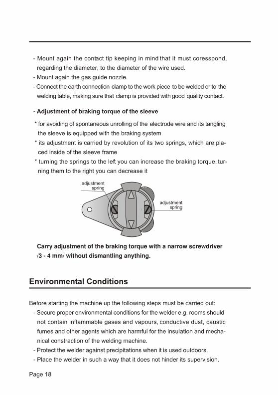
- Mount again the contact tip keeping in mind that it must coresspond,
regarding the diameter, to the diameter of the wire used.
- Mount again the gas guide nozzle.
- Connect the earth connection clamp to the work piece to be welded or to the
welding table, making sure that clamp is provided with good quality contact.
Environmental Conditions
Before starting the machine up the following steps must be carried out:
Carry adjustment of the braking torque with a narrow screwdriver
- Secure proper environmental conditions for the welder e.g. rooms should
not contain inflammable gases and vapours, conductive dust, caustic
fumes and other agents which are harmful for the insulation and mecha-
nical constraction of the welding machine.
- Protect the welder against precipitations when it is used outdoors.
- Place the welder in such a way that it does not hinder its supervision.
the sleeve is equipped with the braking system
* for avoiding of spontaneous unrolling of the electrode wire and its tangling
* its adjustment is carried by revolution of its two springs, which are pla-
* turning the springs to the left you can increase the braking torque, tur-
ced inside of the sleeve frame
ning them to the right you can decrease it
- Adjustment of braking torque of the sleeve
adjustmentspring
adjustmentspring
/3 - 4 mm/ without dismantling anything.
Page 18

Preparation for Welding Works
- Connect the return welding cable to the welding piece by means of the
clamp.
- Connect the shielding gas cylinder to the gas input through thereducer.
- Connect the mains cable of the welding machine to the mains socket of
an one-phase network 240V, 50Hz.
- Switch the machine on by means of the selector - the power sup-0
1
354
26
01
354
26
ply indicator lights.
- Insert the electrode wire.
- Choose suitable settings of welding parameters according to the select-
ing mode and thickness of welding elements.
- Select the range of the welding voltage by means of the selectr .
- Adjust the welding current by means of the knob of the electrode wire
feed speed control .
- Obeying the appropriate rules you can begin to weld.
12
3
4
56
78
9
10
11
served as well as when the smell of burnt insulation is noticed and
of the machine must be stopped and detailed survay or in case of
- In case an excessive overheating is stated or smoke or fire is ob-
an excesive trembling, vibrations or noise take place the operation
necessity a test of technical state must be carried out.
- Too high humidity may lead to the deterioration of the state of insu-
protected against overheating by means of the temperature limiter.
- In case of mechanical damage e.g. after a fall of the welder from
- The same refers to a situation when interlocking of current circuit or
a considerable hight follow as above.
a voltage on the cabinet is stated.
lation of the machine and can create electric shock hazard.
- During the operation some of internal parts of the welder get hot. Their
if the contacts get very hot it is a sign that their condition is bad.
- Too high temperture should not occure in connection contacts and
temperature can reach up to 100 C - it is normal and the machine is
Page 19
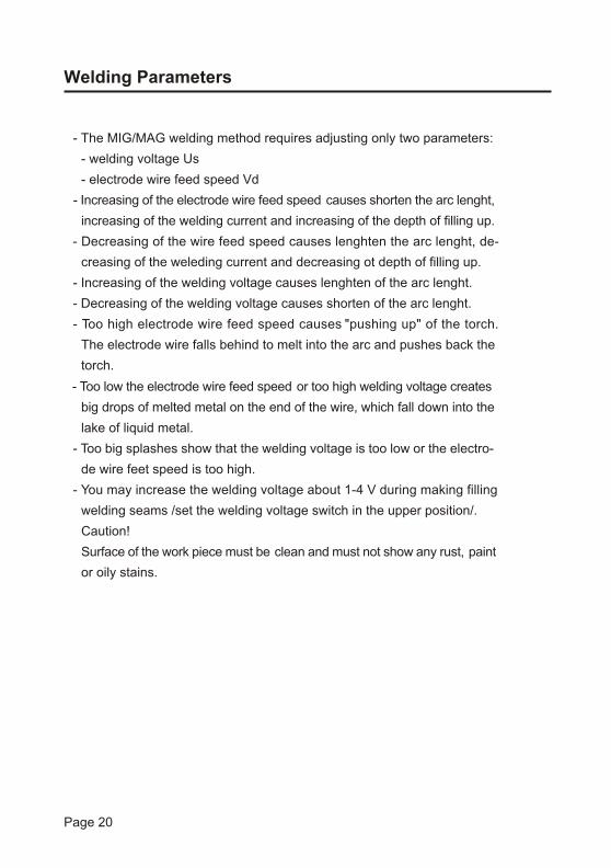
- Too low the electrode wire feed speed or too high welding voltage creates
big drops of melted metal on the end of the wire, which fall down into the
lake of liquid metal.
- Too big splashes show that the welding voltage is too low or the electro-
de wire feet speed is too high.
- You may increase the welding voltage about 1-4 V during making filling
welding seams /set the welding voltage switch in the upper position/.
Caution!
Surface of the work piece must be clean and must not show any rust, paint
or oily stains.
Welding Parameters
- The MIG/MAG welding method requires adjusting only two parameters:
- welding voltage Us
- electrode wire feed speed Vd
- Increasing of the electrode wire feed speed causes shorten the arc lenght,
increasing of the welding current and increasing of the depth of filling up.
- Decreasing of the wire feed speed causes lenghten the arc lenght, de-
creasing of the weleding current and decreasing ot depth of filling up.
- Increasing of the welding voltage causes lenghten of the arc lenght.
- Decreasing of the welding voltage causes shorten of the arc lenght.
- Too high electrode wire feed speed causes "pushing up" of the torch.
The electrode wire falls behind to melt into the arc and pushes back the
torch.
Page 20

Storage and Transportation
- The welding machine should be stored in close rooms featering temperatu-
res ranging from -10 C to +40 C and relative humidity up to 80 %.
- The room should be free of caustic, conducting dust and other environ-
mental agents.
- It is recommended to store welders in their packagings.
- Transportation inside the factory can be carried out by using own chassies
of the machine provided the roads are rather smooth and at low speed up
to 5 km/h, optionally a crane or an overhead trevelling crane can be used.
- For transportation on longer distances the welder should be packed in
the way protecting it against mechanical damages.
- For transportation any means of transport can be used.
- During the transport welding machines should be placed along the moving
direction and protected against rolling or moving as well as against preci-
pitations.
Spot Welding
The welding machine Compact 185 can use to spot welding. The spot wel-
ding process is recommended to join thin elements e.g. sheet metal.
For this you must replace the nozzle with a special one, which is equipped
with pins. Those pins enable to tighten joining elements and free flow of the
shielding gas.
- Set the welding parameters as above.
- Quality of the welding seams depend on the welding time.
- Too long the welding time may cause smelting of the material.
- Too short the welding time may cause no connection.
Recommendation:
Page 21

Care and Maintenance
Routine maintenance
- general rules of personal and fire protection referring to welding opera-
Warning!
nce and service!
Mains of the welding rectifier must be unplugged during maintena-
Only qulified personnel should perform maintenance and service!
- check the state of all connections - they must be change if necessary
and wash a refill of the welding torch with petroleum spirits
- check and straighten all of screw connections
- after each repair perform proper measurements of using safety
Periodic maintenance
tions must be observed
- check condition of insulation and connections of the current cables,
- remove the metal spatters from the gas nozzle of the welding torch - they
- check state of the welding torch - it must be cleaned if necessary
- in case when any metal fillings of the electrode wire are noticed it is ne-
- before installing a new reel of the electrode wire it is necessary to un-
- grease the gas nozzle of the welding torch with an antisplashing agent
welding torch and power supply cable
may cause disturbances in the shield of the lake of liquid metal
- check condition and work of the cooling fan - ventilator slots cannot be
cessary to check whether the pressure of the driving roll is proper to the
wire diameter and decrease it properly
screw the gas nozzle and the contact tip and to clean the shield runner
using compressed air - it should prevent from electrode wire blocking
blocked
- if any damage appears you should give the welder back to the service
- dust all parts and the cabinet of the welding machine very methodically
Page 22

Lack of the electrode
wire feeding /motor
does not work/
Work clamp is too weakly fasten Fasten the clamp properly
Shield runner of the electrode
wire is contaminated
Clean the shield runner of the
electrode wire
Groove of the roll is not com-
patible to the wire diameter
Use the roll with the groove
according to the wire diameter
Electrode wire is blocked into
the contact tip
Unblock the electrode wire in-
to the contact tip
Irregular feed of the
electrode wire
Arc does not start
Too long or irregular
arc
Too short arc
After switching on
the idicator lamp
does not light
Motor is damaged
Contact tip is damaged
Lack proper contact of the
work clamp
Welding voltage is too high
Welding voltage is too low
Lack of supply voltage
Damaged switch
Damaged idicator lamp
Wire feeding speed is too low
Wire feeding speed is too high
The machine should be given
to the service back
Change the contact tip for
the new one
Straighten contact of the work
clamp
Decrease the welding voltage
Increase the welding voltage
Connect supply voltage
Change the switch
Change the bulb
Increase the wire feed speed
Increase the wire feed speed
The control circuit US-45S
is damaged
Groove of roll is dirty, dama-
ged or it is not compatible to
the wire diameter
Clean the groove of the roll
or change it according to the
wire diameter
Fault Cause Remedy
Trouble Shooting Guide
Page 23
The machine should be given
to the service back
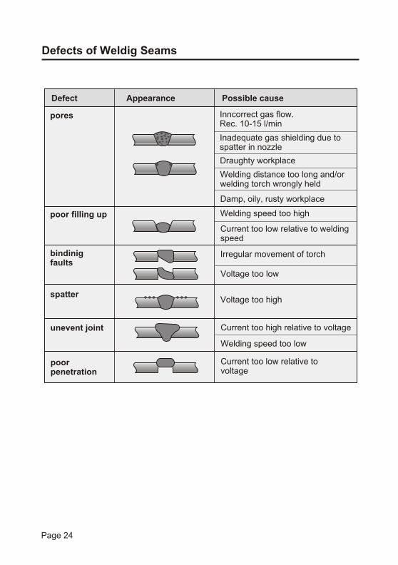
Inncorrect gas flow.Rec. 10-15 l/min
Inadequate gas shielding due tospatter in nozzle
Draughty workplace
Welding distance too long and/orwelding torch wrongly held
Welding speed too high
Voltage too high
Current too low relative tovoltage
Irregular movement of torch
Current too low relative to weldingspeed
Welding speed too low
Current too high relative to voltage
Voltage too low
Damp, oily, rusty workplace
poor filling up
spatter
unevent joint
poorpenetration
bindinigfaults
pores
Defect Appearance Possible cause
Defects of Weldig Seams
Page 24

01
354
26
COMPACT 185
LINCOLNELECTRIC
R
CES
V
12
3
4
56
78
9
10
11
5
4
6
&
2
7
8
*
4
1
3
Spare Parts List
Page 25
}
31
2627
35
30
_{
33
28
37
34
38
36
32
ZAK£ADY URZ¥DZEÑ TECHNOLOGICZNYCHUL.JANA III SOBIESKIEGO 19a 58-260 BIELAWA
Typ: Compact 185 No:
LINCOLNELECTRIC
R
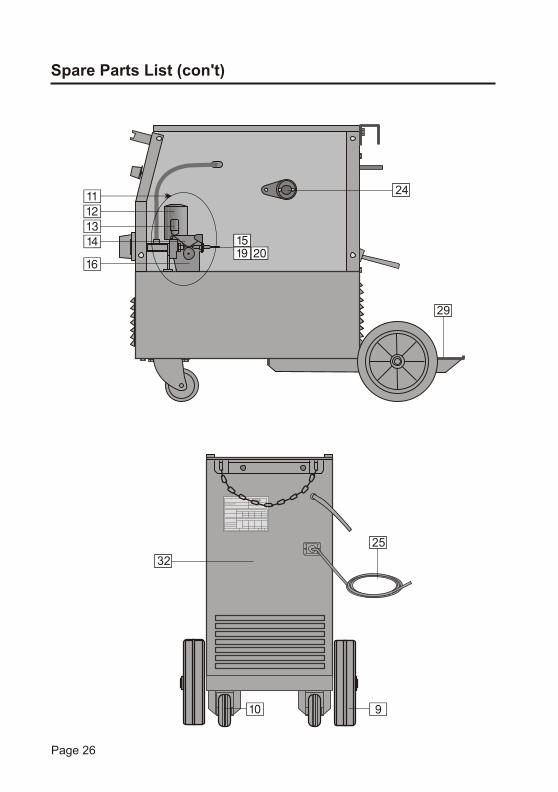
Spare Parts List (con't)
90
Page 26
25
(%
24!
@
#
$
^)
29

26
27
28
23
21
24
25
1
P162KC 10kA20%KCF1 6x16
Index
1
1158-113-005R
C-3891-001-1R
D-5578-094-2R
C-2985-005-5R
1158-910-025R
1361-599-364R
U0.8-1.0-1.2-1.6
V 0.6-0.8-1.0-1.2
BP10115-1
BP10084-1
0972-423-004RELRA 5536, 230V
1111-722-045R
B-6713-009-1R
SCP80 1029-660-080-R
1029-660-200R
0873-100-092RMEZAXIAL 3141
1115-212-211R
1115-212-206R
CI 16 220-230 V
CB-NC
LS3N1 with yellow diode 0917-421-043R
0917-421-041R
1115-260-053R£K15/5.8718
LS3P1
C-4244-330-1R
D-4639-030-1R
C-4244-329-1R
ring19a
20
20a
mains cable
potentiometer
knob
1
1
1
16
1 main transformer T 1
2rectifying set V
induktor L
switch S1
1
1
1
3
lamp H1 1
4
5
7
6
8
lamp H2
contactor K
auxiliary contact block
fan motor M1
1
1
1
1
Spare Parts List (con't) - CODE NO 1095, K NO K10314-1
9
10
11
12
13
14
15
17
18
19
wheel
turning wheel
feeding unit
motor
gas valve
active roll V
active roll U/Al/
EURO socket
sleeve
2
2
1
1
1
1
1
1
1
Pos. Description Type Qty
Page 27
1115-769-087RCZOT AO2/96-103temperature sensor 1
1
0918-432-076R
1361-599-397R
C-2774-081-1R
D-4732-003-1R
D-2535-012-1R
inlet guide
fixing arm
pressure arm
feed plate
control ciruit
1
1
1
1
Fi200
US-45S
11361-599-646Rring
22 D-1829-066-1Routlet guide 1
1361-599-708REuro cover 1
D-5578-049-2Rreturn cable

Page 28
Index
B-7639-377-1R
C-2722-080-1/08R
D-3721-325-1/08R
C-2774-087-1/08R
D-2721-965-1R
2719-107-234R
C-2773-084-1/08R
C-2721-884-2/33R
D-3721-326-1/08R
D-2721-966-1R
D-3721-319-1/08R29 lower shelf 1
31left side panel with label
rear panel
side panel
1
1
1
32
top panel 1
33
34
35
36
side panel with label
label
base
1
1
1
Spare Parts List (con't) - CODE NO 1095, K NO K10314-1
37
38
39
divider panel
shelf
harness
1
1
1
Pos. Description Type Qty
2719-107-234Rlabel 1
D-3721-343-1R30 front panel with label, S 1
Page 29
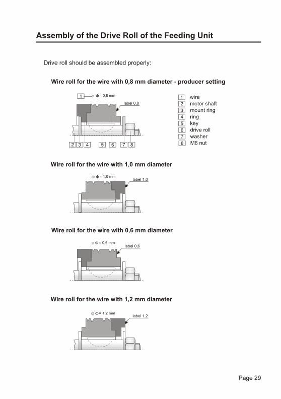
Assembly of the Drive Roll of the Feeding Unit
11
4
4
2
2
5
5
7
7
3
3
6
6 88
Wire roll for the wire with 0,8 mm diameter - producer setting
Wire roll for the wire with 1,0 mm diameter
Wire roll for the wire with 0,6 mm diameter
Wire roll for the wire with 1,2 mm diameter
label 0,8
label 1,0
label 0,6
label 1,2
wire
ring
motor shaft
key
washer
mount ring
drive roll
M6 nut
= 0,8 mm
= 1,0 mm
= 1,2 mm
= 0,6 mm
Drive roll should be assembled properly:

Notes
Page 30

I-207-327-1Rev.1 12.2008
producer

I-207-327-1Rev.1 12.2008
producer