To: Holders of the Geometric Design Guide for Canadian ... · PDF fileTo: Holders of the...
37
To: Holders of the Geometric Design Guide for Canadian Roads (1999) From: Transportation Association of Canada Subject: June 2014 Errata to the Geometric Design Guide for Canadian Roads The following pages contain minor corrections to the Geometric Design Guide for Canadian Roads. Both the front and back of the revised page have been supplied so that you can print them 2-sided and replace the existing pages within the manual. Only the page with the June 2014 date contains information that has been changed. If you have any questions please do not hesitate to contact the TAC secretariat.
Transcript of To: Holders of the Geometric Design Guide for Canadian ... · PDF fileTo: Holders of the...

To: Holders of the Geometric Design Guide for Canadian Roads (1999) From: Transportation Association of Canada Subject: June 2014 Errata to the Geometric Design Guide for Canadian Roads The following pages contain minor corrections to the Geometric Design Guide for Canadian Roads. Both the front and back of the revised page have been supplied so that you can print them 2-sided and replace the existing pages within the manual. Only the page with the June 2014 date contains information that has been changed. If you have any questions please do not hesitate to contact the TAC secretariat.

Geometric Design Guide for Canadian Roads
Page 2.2.12.5June 2014
Figure 2.2.12.2 Staging of a New Four-Lane Undivided Arterial Street
method Bmethod A
RO
WR
OW
RO
W
RO
W
RO
W
curb
curb
sid
ewal
k
sid
ewal
k
(exi
stin
g)
(exi
stin
g)
(exi
stin
g)
RO
W
RO
W
RO
W
sid
ewal
kstage I
stage II
dra
inag
e d
itch
sho
uld
er
tem
po
rary
cu
rb o
r sh
ou
lder
C L

Page 2.2.12.6 September 1999
Cross Section Elements
Geometric Design Guide for Canadian Roads
Page 2.3.1.5December 2009
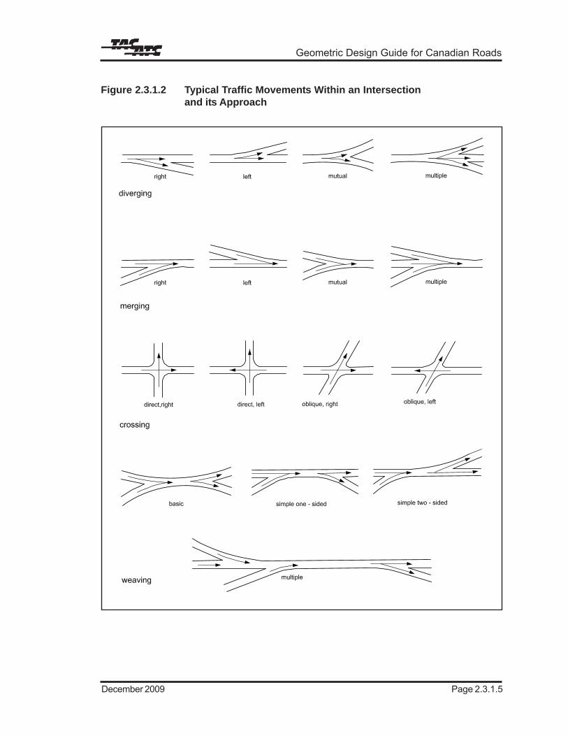
Figure 2.3.1.2 Typical Traffic Movements Within an Intersectionand its Approach
123456789123456789123456789
12345678901234123456789012341234567890123412345678901234123456
123456
Intersections
Page 2.3.1.6 June 2014
Diverging and merging may be to the right, tothe left, mutual or multiple.
Crossings are termed “direct” if the angle ofintersection is between 70° and 110° (right-angled intersection) or “oblique” if the intersectionangle is less than 70° or greater than 110° (obliqueintersection).
Weaving consists of the crossing of trafficstreams moving in the same direction. It isaccomplished by a merging manoeuvrefollowed by a diverging manoeuvre. Weavingsections may be considered to be simple ormultiple with a further subdivision into one-sidedor two-sided weaving.
Conflicts
Every rural and urban at-grade intersection hasconflict areas. One of the main objectives ofintersection design is to minimize the severityof potential conflicts between all intersectionmanoeuvres.
A traffic conflict occurs whenever the pathsfollowed by vehicles diverge, merge or cross.
The number of traffic conflicts at intersectionsdepends on:
• the number of one-way or two-wayapproaches to the intersection
• the number of lanes at each approach
• signal control
• traffic volumes
• the percentage of right or left turns
As an example, Figure 2.3.1.31,6 shows conflictpoints for a T-intersection (three-legged) and across-intersection (four-legged). With theaddition of a single intersection leg, the numberof conflict points increases from 9 to 32. Thedifference in collision rates at three- and four-legged intersections is also illustrated onFigure 2.3.1.3. It is shown that as traffic volumeincreases, the role the increased number ofconflict points at a four-legged intersection playsin collision rate, becomes more significant.6 The
designer should be cautioned, however, that thenumber of conflict points for offset, or split T-intersection arrangements, as shown in Figures2.3.1.1 and 2.3.2.1, would not be 18 (2 x 9);instead the number of conflict points for this typeof intersection configuration (two T-intersections) would likely be larger than at asingle cross-intersection with 32 conflict points.
The conflict areas are divided into twocategories:
• major conflict areas where head-on, right-angle or rear-end collisions may occur
• minor conflict areas where sideswipecollisions may take place
Illustrations of traffic conflict areas are shownin Figure 2.3.1.4.1 It should be noted that the90o T- and cross-intersections have thesmallest conflict areas in comparison to theskewed cross-intersection and the multi-leggedintersection which have the largest.
Channelized intersections with auxiliary lanesfurther reduce the conflict area size and thenumber of vehicles passing through the sameintersection point by separating trafficmovements into definite paths of travel usingpavement markings and islands. For furtherinformation on channelized intersections, seeSection 2.3.6.
In urban environments especially, conflicts canalso occur between vehicles and pedestrians,and vehicles and bicyclists. Vehicles typicallyconflict with pedestrian crossing manoeuvres.Vehicles can conflict with any bicyclemanoeuvre. The 90° T- and cross-intersectionsare the most straightforward intersections forpedestrian and bicycle manoeuvres,channelization may increase vehicle/pedestrianconflicts as pedestrians attempt to cross theturning roadway.
Prohibited Turns
Prohibited turns can be discouraged by designingtight or extended curb returns which make itdifficult to achieve these turns. Channelizationis also used to restrict or prevent prohibited,undesirable or wrong-way movements. In

Geometric Design Guide for Canadian Roads
June 2014 Page 2.3.1.11
and limitations. When a design is incompatiblewith the attributes of a driver, the chances fordriver error increases. Inefficient operation andcollisions are often a result.3
In general, traffic volume is the most significantcontributor to intersection collisions. Typically,as traffic volumes increase, conflicts increase,and therefore the number of collisions increase.5
Severity of collisions varies only slightly amongrural, suburban and urban intersections; thepercent of severe collisions is approximately 5%higher for rural intersections.5
Other elements related to intersection collisionrates include geometric layout and trafficcontrol.3 As previously noted, traffic controlmeasures are not addressed in this document.The relationship of specific geometric elementsand safety is described below:
Type of Intersection
In rural settings, four-legged intersectionstypically have higher collision rates thanT-intersections (three-legged) for stop andsignal controls.7
In urban settings, very little difference in collisionrates between four-legged and T-intersectionswas found for low volume intersections(Average Daily Traffic under 20 000); however,for larger volumes, the four-legged intersectionwas found to have the higher collision rate.8
Sight Distance
In both an urban and a rural setting,studies have shown that the collision rate atmost intersections will generally decrease whensight obstructions are removed, and sightdistance increased.3
Channelization
In a rural environment, it was found that left-turn lanes would reduce the potential of passingcollisions.9
In an urban setting, it was found that multi-vehicle collisions decrease when lane “dividers”(raised reflectors, painted lines, barriers or
medians) are used; however the use of left-turnlanes was not considered effective as a collisioncountermeasure but was considered effective asa means of increasing capacity.8
Cross Section
Safety considerations for cross sectionelements, such as lane width, are addressedin Chapter 2.2.
2.3.1.7 Intersection SpacingConsiderations
Both rural road and urban road network spacingis often predicated on the location of the originalroad allowances prior to urban development.The systems of survey employed in the layoutof original road allowances vary from region toregion across Canada. As rural areas urbanize,the development of major roads generallyoccurs along these original road allowances,and consequently road networks vary fromregion to region. As examples, the land surveysystem in Ontario has created a basic spacingbetween major roads of 2.0 km, whereas theland survey system in the prairie provinces hasresulted in a 1.6 km grid.
As development occurs, this spacing is oftenreduced. In areas of commercial or mixed usedevelopment, the traffic generated byemployment and retail shopping may result ina reduced arterial spacing. In downtown areas,this spacing could be reduced further asdetermined by the traffic needs and thecharacteristics of the road network.
The spacing of intersections along a road inboth an urban and rural setting has a largeimpact on the operation, level of service, andcapacity of the roadway. Ideally, intersectionspacing along a road should be selected basedon function, traffic volume and otherconsiderations so that roads with the highestfunction will have the least number (greatestspacing) of intersections (the relationship ofroad classification and the preferred functionalhierarchy of circulation is described inChapter 1.3 of this Guide). However, it is oftennot always possible to provide ideal intersection

Intersections
Page 2.3.1.12 December 2009
spacing, especially in an urban setting. As such,the following should be considered:
Arterials
Along signalized arterial roads, it is desirableto provide spacing between signalizedintersections consistent with the desired trafficprogression speed and signal cycle lengths. Byspacing the intersections uniformly based onknown or assumed running speeds andappropriate cycle lengths, signal progressionin both directions can be achieved. Progressionallows platoons of vehicles to travel throughsuccessive intersections without stopping. Fora progression speed of about 50 km/h and acycle length of 60 s, the corresponding desiredspacing between signalized intersections isapproximately 400 m. As speeds increase theoptimal intersection spacing increasesproportionately. Further information on thespacing of signalized intersections is providedin the Subsection 2.3.1.7.
A typical minimum intersection spacing alongarterial roadways is 200 m, generally onlyapplicable in areas of intense existingdevelopment or restrictive physical controlswhere feasible alternatives do not exist. The200 m spacing allows for minimum lengths ofback to back storage for left turning vehicles atthe adjacent intersections.
The close spacing does not permit signalprogression and therefore, it is normallypreferable not to signalize the intersection thatinterferes with progression along a majorarterial. Intersection spacing at or near the200 m minimum is normally only acceptablealong minor arterials, where optimizing trafficmobility is not as important as along majorarterials.
Where intersection spacing along an arterialdoes not permit an adequate level of trafficservice, a number of alternatives can beconsidered to improve traffic flow. Theseinclude: conversion from two-way to one-wayoperation, the implementation of culs-de-sac forminor connecting roads, and the introductionof channelization to restrict turning movementsat selected intersections to right turns only.
On divided arterial roads, a right-in, right-outintersection without a median opening may bepermitted at a minimum distance of 100 m froman adjacent all-directional intersection. Thedistance is measured between the closestedges of pavement of the adjacent intersectingroads.
In retrofit situations, the desired spacing ofintersections along an arterial is sometimescompromised in consideration of other designcontrols, such as, the nature of existing adjacentdevelopment and the associated access needs.
Collectors
The typical minimum spacing between adjacentintersections along a collector road is 60 m.
Locals
Along local roads, the minimum spacingbetween four-legged intersections is normally60 m. Where the adjacent intersections arethree-legged a minimum spacing of 40 m isacceptable.
Cross Roadway Intersection Spacing Adjacentto Interchanges
The upper half of Figure 2.3.1.6 indicates theintersection spacing along an arterial crossingroad approaching a diamond interchange. Thesuggested minimum distance between acollector road and the nearest ramp, asmeasured along the arterial cross road, is200 m (dimension A
c on Figure 2.3.1.6). In the
case of an arterial/arterial cross roadintersection, this minimum offset distance fromthe ramp is normally increased to 400 m(dimension A
a on Figure 2.3.1.6). The same
dimensions apply to arterial cross roadsapproaching parclo-type interchanges as shownon the lower half of Figure 2.3.1.6.
Ramp Intersection Spacing at Interchanges
The upper half of Figure 2.3.1.6, as well asFigure 2.3.1.7, illustrate the suggested andminimum intersection spacing and laneconfigurations on the cross road at a typicaldiamond interchange. The two differentchannelization treatments illustrate the following

Geometric Design Guide for Canadian Roads
September 1999 Page 2.3.2.1
2.3.2 ALIGNMENT
2.3.2.1 Design Speed
The following is a discussion of design speedas it pertains to intersections. Chapter 1.2presents discussion on roadway design speed.
Rural
In a rural environment, the design speed of themajor roadway is used for the main intersectionapproaches to determine taper lengths,deceleration and acceleration lengths, and othergeometric features specific to traffic on themajor roadway.
Design speed is typically not reduced at ruralintersections where drivers are accustomed tolong periods of uninterrupted travel. Inattentivedrivers should be alerted to the fact that anintersection is ahead and should have enoughtime to react accordingly by providing adequatedeceleration and acceleration lengths, etc. forthe design speed.
Urban
In general, it is desirable to maintain the designspeed of a roadway as it passes through anintersection, particularly for a roadway wherethe traffic has or may have the right of waythrough the intersection. Examples of thissituation are:
• an intersection controlled by traffic signalsor which may be controlled by signals inthe future
• a major road crossing a minor road wherethe minor roadway has a stop or yieldcontrol, and the major roadway is notcontrolled
• an uncontrolled intersection
For an urban roadway controlled by a yield signat an intersection, approach speeds in the orderof 25 km/h are common. A suitable designspeed for such an approach roadway within thezone of the intersection would be 35 km/h.
Where traffic on a minor roadway is, and willlikely always be, controlled by a stop sign at anintersection, the design speed of the minorroadway can be reduced through theintersection area. As a basic requirement, it isimportant to provide sufficient sight distance forthe design vehicle to safely depart from thestopped position and make the desiredmanoeuvre through the intersection.
If a design speed equal to or greater than theexisting posted speed cannot be achievedthrough an intersection, changes to the postedspeed, the implementation of speed advisorysigning or similar treatment should beconsidered. Sound judgement is called for inselecting the design elements that meet theexpectations of the driver.
2.3.2.2 Horizontal Alignment
Intersections are ideally located on tangentsections. Location of intersections on curves isnot desirable due to decreased visibility,increased conflict potential for vehicles crossingthe major roadway, and complications withroadway superelevation and pavementwidening on curves. Intersections on curves arediscussed further in Subsection 2.3.2.5.
It is desirable that intersecting roads meet at,or nearly at, right angles.
The benefits of a 90° angle of an intersectionare:
• reduced size of conflict area (seeFigure 2.3.1.4)
• improved driver visibility
• more favourable condition for drivers tojudge the relative position and relativespeed of an approaching vehicle and todecide when to enter or cross the majorroad
• reduced length of time of a crossingmanoeuvre
• general decrease in severity of collisions(collisions occurring at an impact angle of

Intersections
June 2014Page 2.3.2.2
90° are generally less severe than thoseoccurring at angles of greater than 90°)1
While crossing at 90° is preferable in mostcases, it is occasionally necessary and evenadvantageous to skew the crossing (forexample, to favour a heavier turningmovement). However, angles less than 70°andgreater than 110° are typically not desirable. Forexample, at a skewed T-intersection with anangle less than 70° certain undesirableconditions exist because of the flat angle ofentry. Vehicles which do stop are standing in aposition that affords poor visibility for the driverto judge the speed and the distance ofapproaching vehicles on the major roadway.Also, for a skew right, vehicles leaving the majorroadway to enter the minor roadway with a rightturn are encouraged to do so at high speedsand for a skew left, drivers tend to cut the cornerat higher speeds, thereby travelling in theopposing lane for a considerable distance andcreating a safety concern.1
Particular consideration should be given tomaintaining an angle of skew within 10° of rightangle (i.e. between 80° and 100°), when any ofthe following conditions exist:
• two minor roadways with design hourvolume (DHV) greater than 200 v/h (on bothroadways) intersect
• minor roadway with DHV greaterthan 200 v/h intersecting with a major road
• two major roads intersect
• either of the intersecting roadways hasmore than two basic lanes
• sight distance is at a minimum
• design speed on either intersectingroadway for through traffic is greater than80 km/h1
In the case of existing roads that intersectbetween 70° and 80° (or 110° and 100°) withno collision or performance concerns, arealignment to 80° (or 100°) may not be costeffective.
The practice of realigning roads intersecting atacute angles in the manner shown inFigure 2.3.2.1 (A and B) is beneficial. Ideally,the curves used to realign the roads would avoida decrease in operating speed along therealigned roadway. The practice of constructingshort radii horizontal curves on minor roadwayapproaches to achieve right-angle intersectionsmay be acceptable but not necessarily desirablein the urban and rural settings. These curvesresult in increased lane infringements becausemotorists tend to drive flatter curves byencroaching on a portion of the opposite lane.Also, the traffic control devices at theintersection may be obscured resulting in theneed for the installation of advanced warningsigning.11
It should be noted that although examples Cand D on Figure 2.3.2.1 provide poor networkcontinuity, both examples may be acceptablealternatives. If implemented, suitable physicalbarriers or other obstructions should be placedacross the former right of way of the minor road.These visual obstructions are desirable to alertthe driver on the minor road that the road isrealigned and is no longer on continuous tangentthrough the intersection. Assuming a four-laneundivided arterial road, the splitT-intersection arrangement, example C (offset-right), introduces back-to-back left turns on themajor roadway, which are generally undesirableunless left-turn auxiliary lanes can be provided.This layout, however, has the advantage ofrequiring the driver, wishing to cross the majorroad, to select a gap in only the trafficapproaching from the left, and then make aconventional right turn followed by a left-handmerge manoeuvre to reach the left-turn auxiliarylane. However, if no left-turn lane is provided,vehicles travelling along the minor roadway mayhold up traffic while waiting for a gap to turn left.With example D (offset-left), the turns introducedon the major roadway by the minor roadwaycrossing manoeuvres are right turns only, whichminimize the impact on through traffic on themajor roadway. However, the driver attemptingto cross on the minor roadway is required toselect coincidental gaps in the traffic streamsfrom both directions on the major roadway.Moreover, the driver is required to makeright-hand merge manoeuvres on the major

Geometric Design Guide for Canadian Roads
September 1999 Page 2.3.2.3
Figure 2.3.2.1 Examples of Realignment of Intersections
roadway

Intersections
June 2014Page 2.3.2.4
roadway which may be more hazardous. Inconclusion, either example C or D may beacceptable solutions in urban areas. The trafficconditions and opportunity to incorporateauxiliary lanes are important considerations inassessing the merits of each. Where significantthrough volumes exist or are expected alongthe minor roadway crossing the major roadway,the split T-intersection realignments, examplesC and D, are generally considered lessdesirable than the types of realignments shownas examples A and B on Figure 2.3.2.1.
Where the major road is curving and a minorroad constitutes an extension of one tangent,realigning the minor road is advantageous, asshown on example E of Figure 2.3.2.1, to guidetraffic onto the main roadway and improve thevisibility at the point of intersection. This practicemay have the disadvantage of adversesuperelevation for turning vehicles and mayrequire further study when curves have highsuperelevation slopes and when the approachroadway has adverse grades and a sightdistance restriction due to the grade line.11
A suggested tangent length ‘L’ of 20 m or greateron the minor road is shown on all examples onFigure 2.3.2.1. The designer should ensure thatthe tangent length is long enough to provideadequate sight distance and to adjust the minorroadway cross-slope from the curve to theintersection.
For a realigned road, the original roadwaypavement should be removed and appropriatelandscaping used to eliminate visual distractionsfor drivers and to minimize potential for thedriver to perceive that the roadway continuesstraight.
In developed areas realignments of this naturemay not be feasible due to the constraints ofexisting buildings or high property values. Ifexcessive collision rates are experienced andgeometric changes are not feasible, it may beadvantageous to restrict or eliminate the morehazardous turns. As a result, otherimprovements at adjacent intersections may beneeded to suitably accommodate the alteredtravel patterns. Signalizing the intersection mayalso be considered. However, possible adverse
effects, such as delays on the major roadwayshould be taken into account.
2.3.2.3 Vertical Alignment andCross-Slope
Cross-Slope:Major/Minor RoadwayIntersection
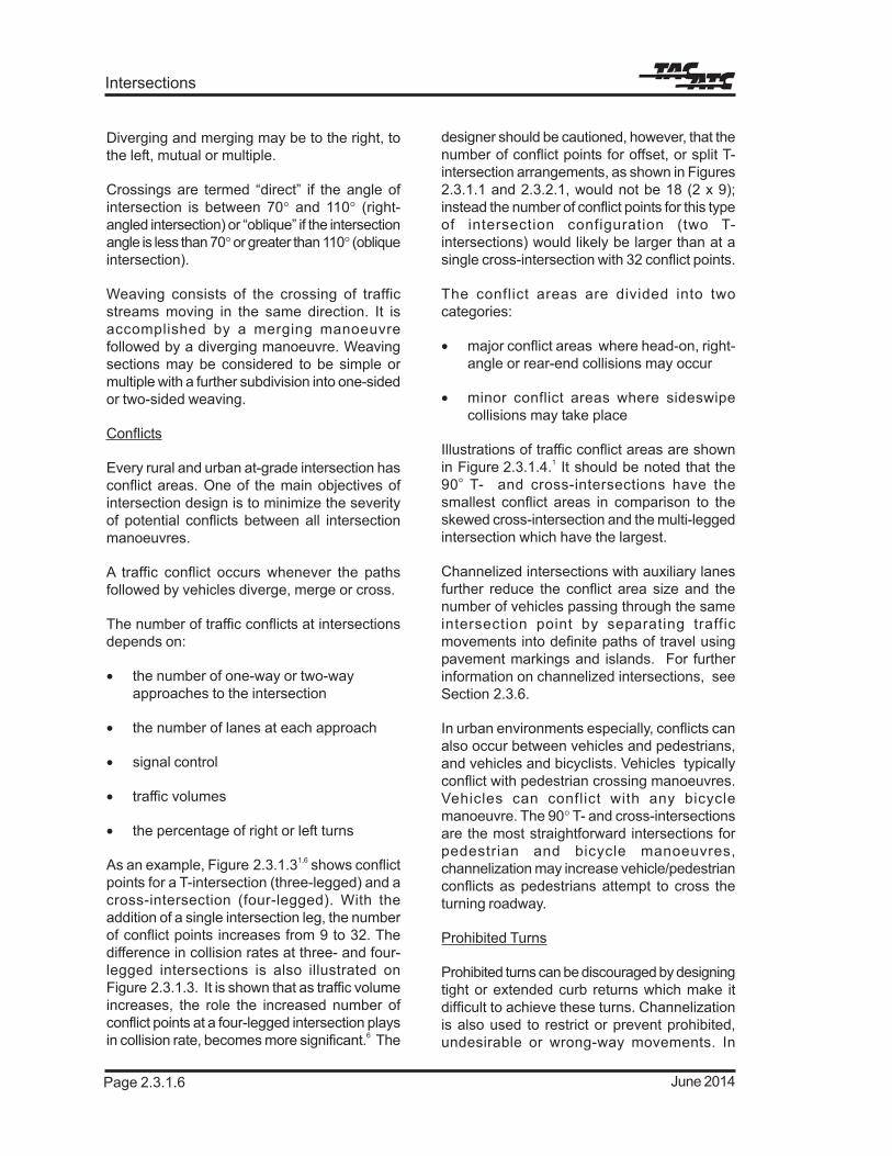
Profiles at intersections are designed inconsideration of the expected operatingconditions including speed, major traffic flowsand sight distance. The profiles of the majorroadway at a major/minor roadway intersectionare normally not adjusted significantly to matchthose of the minor cross roadway. It is normallythe gradient on the intersecting minor roadwaythat is adjusted through the introduction ofsuitable grades and vertical curves prior to theintersection, as shown on Figure 2.3.2.2, insuch a way as not to reduce the sight distances.In certain conditions, however, reducing thenormal cross-slope (typically 2%, seeChapter 2.1) on the major roadway to about 1%may assist in smoothing the profile of the minorroadway as it crosses the major roadway.Cross-slopes can be adjusted to 0.5% to 3.0%without affecting the efficient operation of trafficalong the major roadway in order to enhancethe smooth movement of minor roadway trafficthrough the intersection. Cross-slopes less than0.5% are avoided due to potential drainageproblems. In other conditions, removing thenormal crown of the major roadway and usingthe normal cross-slope rate continuously acrossthe pavement may better match the verticalalignment of the minor roadway. Theseconcepts are illustrated on Figures 2.3.2.2,2.3.2.31 and 2.3.2.41. Changes from cross-slopeto cross-slope should be as gradual and smoothas possible (see Chapter 2.1).
Cross-Slope: Major Road/Major Roadway (ortwo roadways of equal classification)
Where two major roadways (or two roadwaysof equal classification) intersect, the profiles ofeach are often adjusted in an approximatelyequal manner through the intersection area.Thus the cross-slopes of both major roadwayscan be adjusted to a minimum of 0.5% toprovide an equally smooth ride along each

Geometric Design Guide for Canadian Roads
Page 2.3.6.5June 2014
2.3.6.5 Traffic Islands
General
An island is a defined area between traffic lanesfor control of vehicle movements in intersectionareas or for pedestrian refuge. Islands may beraised areas or may be painted. In rural areasthe two most desirable and commonly usedtreatments are the raised island with mountablecurbs and the painted island. In urban areasbarrier curbs are used to protect pedestriansand to reduce the risk of vehicles striking poles,etc.
Delineation and approach end treatment iscritical to good channelization design. Islanddelineation can be divided into the followingtypes:
Curbed Islands
This type can be applied universally andprovides the most positive traffic delineation.Mountable curbs should be used in most cases.In rural areas where curbs are not common,this treatment is often limited to islands of smallto intermediate size. Pedestrian refuge islandsare usually protected with barrier curb.
Painted Islands
This type of island is generally designed inurban or suburban areas where speeds are lowand space is limited. Application of this type ofisland may be considered in rural areas inadvance of raised median island, wheremaintenance and snow removal make curbsundesirable, and where high approach speeds(urban or rural) make a curb a potential hazard.However, snow accumulation can obliteratepavement markings.
Non-Paved Areas Formed by PavementEdges
This type of island is usually used for largerislands at rural intersections where there issufficient space and/or where added expenseof curbs may not be warranted or may pose atraffic hazard. This island type may besupplemented by delineators on posts, other
guide posts, a mounded earth treatment orappropriate landscaping.
Temporary Island Installations
This type is usually constructed of asphaltcurbing, precast bumper curbing or sand bags1.Such islands would typically be used inconstruction work zones.
Islands are grouped into three functionalclasses which are illustrated on Figures 2.3.6.21,2.3.6.31 and 2.3.6.41 and are described below:
Directional
Directional islands control and direct trafficmovements. They guide the driver into theproper channel for the intended route.Directional islands are of many shapes andsizes, depending upon conditions anddimensions. A common form is one of triangularshape to separate right-turning traffic fromthrough traffic.
Divisional
Divisional islands, also called raised medianislands, are introduced at intersections, usuallyon approach legs, to separate streams of traffictravelling in the same or opposite direction.These islands are particularly advantageous incontrolling left turns at skewed intersections andat locations where separate channels areprovided for right-turning traffic.
Two types of divisional islands are commonlyused:
• opposing divisional islands (for T-intersections)
• offset divisional islands (for cross-intersections)
These islands are shown on Figures 2.3.6.51
and 2.3.6.6.1
Where the roadway is on a tangent, reverse curvealignment is necessary to introduce dividingislands. In rural areas where speeds are high,reversals in alignment should have radii of atleast 2000 m. A median on an approach leg may

Intersections
September 1999Page 2.3.6.6
Figure 2.3.6.2 Directional Islands1

Geometric Design Guide for Canadian Roads
Page 2.3.6.9June 2014
be regarded as a divisional island in the vicinityof the intersection.
Refuge
Refuge or pedestrian islands are typicallyconstructed of barrier curb and are used toprotect and aid pedestrians crossing a roadwayor loading and unloading transit riders. Incongested areas, refuge islands also expeditevehicular traffic flow by permitting vehicles toproceed without waiting for pedestrians to crossthe entire roadway.
In studying the need for refuge islands,consideration is given to width of pavement,proximity of traffic signals, right- and left-turningmovements at intersections, sight distances andany other factors that might have a bearing onthe proposed installation. No refuge or loadingisland should be placed where it will beseparated by fewer than two traffic lanes froman adjacent curb, edge of pavement or otherisland.
When designing an island the designer shouldconsider that its location and configuration mayresult in a hazard to the travelling public. It isundesirable to introduce curbed islands in thecentre of a high-speed road as they areconsidered hazardous objects. However,depending on the cross section of the roadway,it often becomes necessary, at signalizedintersections, to place signal poles and islandsin the medians; in these cases barrier curbsshould be used.
Shape
Directional islands are typically triangular inshape and are positioned within the intersectionin consideration of the tracking requirementsof the turning vehicles. The dimensions andexact shape of directional islands are a functionof:
• the corner radii and associated tapers
• the angle of the intersection
• the design vehicle turning path
Divisional islands are normally elongated inshape with edges parallel to the opposingadjacent travel lanes. Divisional islands areoften configured to provide a protected left-turnlane at an intersection approach.
Refuge islands for pedestrians vary in relationto the pedestrian volumes and needs, the widthof the crosswalks, the intersection layout anddesign constraints such as available right ofway.
Size
Islands are usually sufficiently large tocommand attention. The smallest island that isnormally considered is one that has an area of6 m2. Larger islands are required toaccommodate requirements such aswheelchair ramps. Where pedestrian refuge isrequired, a minimum island size of 10 m2 ispreferred to accommodate the curb-cuts andramps as well as pedestrian storage. Island sizegreater than the minimum are advantageousfor clearly defining the desired travel paths, forthe effective placement of traffic signs, trafficcontrol poles and utilities and for pedestrianrefuge and ramps.
Divisional islands introduced at ruralintersections on high-speed roads arepreferably at least 30 m long. Divisional islandsin urban areas are preferably not less than 1.5 mwide and 4 m long.
Where short islands are unavoidable they arepreceded by visibly roughened pavement,raised bars or markings. When situated in thevicinity of a high point in the roadway profile orat or near the beginning of a horizontal curve,the approach end of the island should beextended so as to be clearly visible toapproaching drivers.
Approach End Treatment
Where there are no curbs on the throughroadway approaching an island, the minimumoffset to the edge of a curbed island (i.e. raisedisland) is 0.5 to 1.0 m.
Where the approach roadway has a mountablecurb, a similar curb on the curbed island could

Intersections
September 1999Page 2.3.6.10
be located at the edge of the through lane wherethere is sufficient length of curbed island toeffect a gradual taper from the nose offset. Non-mountable curbs should be offset from thethrough travelled way edge, regardless of thesize of the curbed island, to avoid a sense oflateral restriction to drivers.11
These details are illustrated in Figures 2.3.6.7and 2.3.6.8.
The approach end of an island is designed tobe conspicuous to approaching drivers andshould be clear of vehicle paths, physically andvisually, so that drivers will not veer away from
the island. The approach nose is always offsetwith respect to the island edge. Where feasible,the total nose offset should be 1.0 to 2.0 m fromthe normal edge of the through pavement and0.5 to 1.0 m from the pavement edge of aturning roadway. This is also achieved by agradual widening of the auxiliary lane pavement.
Where the shoulder is carried through theintersection, the island may be placed at theouter shoulder’s edge. Where speeds are highand the island is preceded by an auxiliary lane,it is desirable to offset the nose of large islands0.5 to 1.0 m outside the shoulder’s edge.
Geometric Design Guide for Canadian Roads
Page 2.3.7.5September 1999
Figure 2.3.7.2 Yield Taper at Channelized Intersection, Major Roadway toMinor Roadway1

Cross Section Elements
Page 2.3.7.6 June 2014
Figure 2.3.7.3 Lane Drop, Dual Lane Right-Turning Roadway
1234567123456712345671234567123456712345671234567123456712345671234567123456712345671234567123456712345671234567123456712345671234567123456712345671234567123456712345671234567
a. p
aral
lel d
esig
n (p
refe
rred
)
121212121212121212
111
12121212
1111
1111
12121212
12345671234567123456712345671234567123456712345671234567123456712345671234567123456712345671234567123456712345671234567123456712345671234567123456712345671234567123456712345671234567123456712345671234567
b. ta
pere
d de
sign
(sui
tabl
e fo
r hig
h sp
eed
turn
ing
road
way
s w
ith g
ood
sigh
t dis
tanc
e)

Geometric Design Guide for Canadian Roads
Page 2.3.8.7June 2014
during unsaturated flow conditions. Additionalstorage length must be provided for larger designvehicles.
The minimum storage length that should beprovided is 15 m (see Safety Warrants,Subsection 2.3.8.2).
The Runout Lane
The runout lane terminates the bypass lane onthe far side of the intersection. The width of theparallel section of the runout lane is the sameas that of the bypass lane. The taper lengthvaries with the design speed and is the sameas that applied to the acceleration lane (seeChapter 2.4). The runout lane is shown onFigures 2.3.8.2 and 2.3.8.3.
Left-Turn Lanes on Both Approaches
Two types of left-turn lane designs areapplicable:
• opposing left-turn lanes, seeFigure 2.3.8.51 (a)
• adjacent left-turn lanes, seeFigure 2.3.8.51 (b)
a) Opposing left-turn lanes
The opposing left-turn lanes design is adesirable treatment for new construction ofunsignalized intersections in rural areas. Thisconfiguration reduces the probability of head-on collisions as this configuration has theadvantage of enabling drivers makingsimultaneous left turns to see past each other’svehicle and therefore, this design contributesto the ease and safety of left-turn movements.Visibility of approaching vehicles, however, canbe reduced with larger vehicles in the left-turnlane. This treatment could also be applied tourban intersections where left-turn lanes arerequired.
b) Adjacent left-turn lanes
The provision of adjacent left-turn lanes is notgenerally recommended due to the potential
for collisions caused by visibility problems forleft-turning vehicles. Visibility problems resultfrom the presence of vehicles in adjacent left-turn lanes.
Adjacent left-turn lanes can be designed wherethe intersection is located on or at the base of asteep down grade. The provision of anunobstructed runout lane can help a driver avoidconflicts in adverse weather conditions whenencroachment in the opposing left-turn lane maybe a safety concern.1
Partially Shadowed and Shadowed Turn Lanes
Figure 2.3.8.6 provides examples of minimumdesigns for flared intersections providing a left-turn area for four-lane roadways in rural areas. Inthese examples, the approach/departure and baytapers are combined. This type of layout is oftenreferred to as a partially-shadowed turn lane. Inthis design, deceleration of the turning vehiclesis typically initiated while the vehicle is within orpartially within the through lane. The turn lanearea is not as well defined or protected as is aleft-turn lane with a painted bay taper and/or anintroduced median. Overhead signing may bedesirable.
Figure 2.3.8.7 illustrates a left-turn lane with apainted approach and bay taper median area.The raised divisional island shown is optional but,where space permits, is desirable to assist indelineating the through and turn lanes. This typeof design is commonly known as a shadowedturn lane. The design parameters defined inTables 2.3.8.1 and 2.3.8.2 should be used todefine the geometry of a shadowed left-turn lane.
Introducing Raised Median
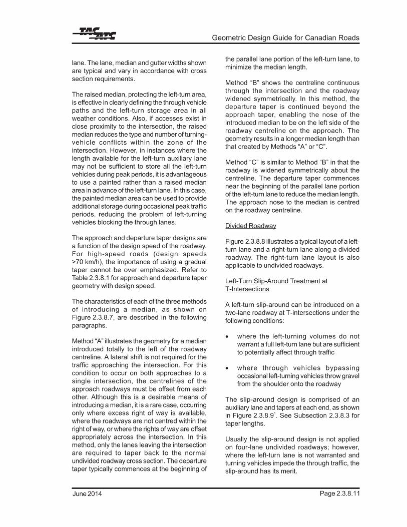
The ideal manner of widening the roadway tointroduce a median is to widen gradually overthe length of a large radius on a main linehorizontal curve. However, since mostintersections occur on tangent alignments, it isoften necessary to use other methods, three ofwhich are illustrated on Figure 2.3.8.7. TheFigure illustrates the geometry of the approachdeparture tapers needed to introduce a raisedmedian and provide a protected left-turn auxiliary

Intersections
September 1999Page 2.3.8.8
Figure 2.3.8.5 Left-Turn Lanes in Two Directions1
Geometric Design Guide for Canadian Roads
Page 2.3.8.11June 2014
lane. The lane, median and gutter widths shownare typical and vary in accordance with crosssection requirements.
The raised median, protecting the left-turn area,is effective in clearly defining the through vehiclepaths and the left-turn storage area in allweather conditions. Also, if accesses exist inclose proximity to the intersection, the raisedmedian reduces the type and number of turning-vehicle conflicts within the zone of theintersection. However, in instances where thelength available for the left-turn auxiliary lanemay not be sufficient to store all the left-turnvehicles during peak periods, it is advantageousto use a painted rather than a raised medianarea in advance of the left-turn lane. In this case,the painted median area can be used to provideadditional storage during occasional peak trafficperiods, reducing the problem of left-turningvehicles blocking the through lanes.
The approach and departure taper designs area function of the design speed of the roadway.For high-speed roads (design speeds>70 km/h), the importance of using a gradualtaper cannot be over emphasized. Refer toTable 2.3.8.1 for approach and departure tapergeometry with design speed.
The characteristics of each of the three methodsof introducing a median, as shown onFigure 2.3.8.7, are described in the followingparagraphs.
Method “A” illustrates the geometry for a medianintroduced totally to the left of the roadwaycentreline. A lateral shift is not required for thetraffic approaching the intersection. For thiscondition to occur on both approaches to asingle intersection, the centrelines of theapproach roadways must be offset from eachother. Although this is a desirable means ofintroducing a median, it is a rare case, occurringonly where excess right of way is available,where the roadways are not centred within theright of way, or where the rights of way are offsetappropriately across the intersection. In thismethod, only the lanes leaving the intersectionare required to taper back to the normalundivided roadway cross section. The departuretaper typically commences at the beginning of
the parallel lane portion of the left-turn lane, tominimize the median length.
Method “B” shows the centreline continuousthrough the intersection and the roadwaywidened symmetrically. In this method, thedeparture taper is continued beyond theapproach taper, enabling the nose of theintroduced median to be on the left side of theroadway centreline on the approach. Thegeometry results in a longer median length thanthat created by Methods “A” or “C”.
Method “C” is similar to Method “B” in that theroadway is widened symmetrically about thecentreline. The departure taper commencesnear the beginning of the parallel lane portionof the left-turn lane to reduce the median length.The approach nose to the median is centredon the roadway centreline.
Divided Roadway
Figure 2.3.8.8 illustrates a typical layout of a left-turn lane and a right-turn lane along a dividedroadway. The right-turn lane layout is alsoapplicable to undivided roadways.
Left-Turn Slip-Around Treatment atT-Intersections
A left-turn slip-around can be introduced on atwo-lane roadway at T-intersections under thefollowing conditions:
• where the left-turning volumes do notwarrant a full left-turn lane but are sufficientto potentially affect through traffic
• where through vehicles bypassingoccasional left-turning vehicles throw gravelfrom the shoulder onto the roadway
The slip-around design is comprised of anauxiliary lane and tapers at each end, as shownin Figure 2.3.8.91. See Subsection 2.3.8.3 fortaper lengths.
Usually the slip-around design is not appliedon four-lane undivided roadways; however,where the left-turn lane is not warranted andturning vehicles impede the through traffic, theslip-around has its merit.

Intersections
September 1999Page 2.3.8.12
Figure 2.3.8.8 Turning Lane Design, Raised Median
Geometric Design Guide for Canadian Roads
Page 2.3.9.1December 2009
2.3.9 TRANSITIONBETWEENFOUR-LANEROADWAY ANDTWO-LANEROADWAY ATINTERSECTIONS
2.3.9.1 Undivided Roadways
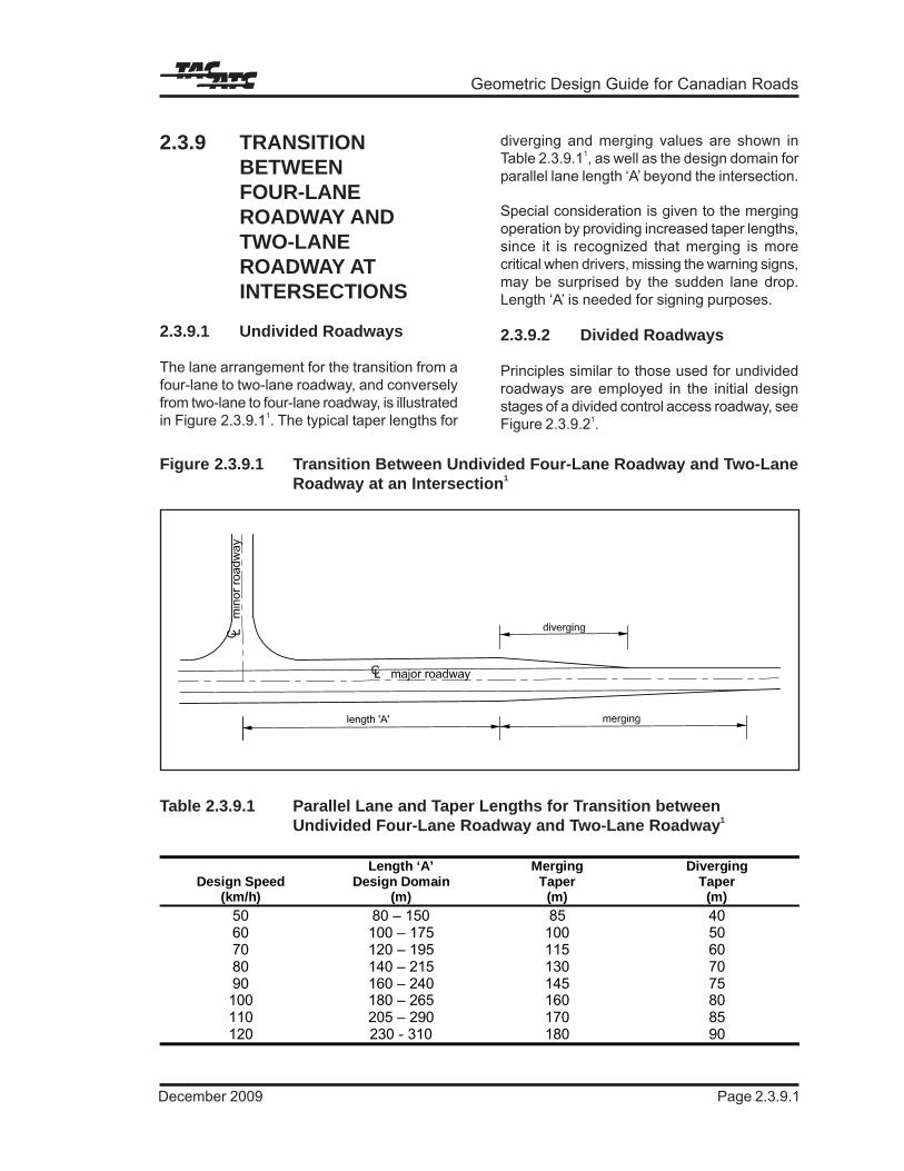
The lane arrangement for the transition from afour-lane to two-lane roadway, and converselyfrom two-lane to four-lane roadway, is illustratedin Figure 2.3.9.11. The typical taper lengths for
diverging and merging values are shown inTable 2.3.9.11, as well as the design domain forparallel lane length ‘A’ beyond the intersection.
Special consideration is given to the mergingoperation by providing increased taper lengths,since it is recognized that merging is morecritical when drivers, missing the warning signs,may be surprised by the sudden lane drop.Length ‘A’ is needed for signing purposes.
2.3.9.2 Divided Roadways
Principles similar to those used for undividedroadways are employed in the initial designstages of a divided control access roadway, seeFigure 2.3.9.21.
Length ‘A’ Merging DivergingDesign Speed
(km/h)Design Domain
(m)Taper
(m)Taper
(m)50 80 – 150 85 4060 100 – 175 100 5070 120 – 195 115 6080 140 – 215 130 7090 160 – 240 145 75100 180 – 265 160 80110 205 – 290 170 85120 230 - 310 180 90
Table 2.3.9.1 Parallel Lane and Taper Lengths for Transition betweenUndivided Four-Lane Roadway and Two-Lane Roadway1
Figure 2.3.9.1 Transition Between Undivided Four-Lane Roadway and Two-LaneRoadway at an Intersection1

Intersections
Page 2.3.9.2 June 2012
1212121212121212121212
End
of r
ight
turn
trea
tmen
t
base
d on
acc
eler
atio
n ne
eds
mer
ging
Figure 2.3.9.2 Transition between Four-Lane Divided and Two-Lane Roadway Merge1

Geometric Design Guide for Canadian Roads
Page 2.4.6.13June 2014
taper form, La, is measured from the end of theramp curve to the point at which the auxiliarylane is 3.5 m wide. Acceleration lengths, La, aremeasured from the end of the ramp controllingcurve. Measurement of Lt and La is illustratedin Figure 2.4.6.1.
The length of an entrance terminal is based onthree factors in combination as discussed inSubsection 2.4.6.2. They are:
• merging with the through traffic
• control speed of the ramp proper
• manner of acceleration
The merging speed with the through traffic isassumed to be the range of operating speedsused in Chapter 1.2.
The control speed of the ramp proper at theupstream of the entrance terminal is included inthe range of ramp design speeds in Table 2.4.6.1.The speed change lane lengths correspondingto the ramp control speeds, which are governedby the design speed of the turning roadwaycurve, are shown in Table 2.4.6.5.
The manner of acceleration assumes an increaseof speed based on the acceleration of passengercars tested in the U.S.3,14
Where acceleration lanes are on grades steeperthan 3%, the length shown in Table 2.4.6.5 shouldbe adjusted by the appropriate grade factor inTable 2.4.6.3.
The length of an entrance terminal also dependson the relative volumes of through and enteringtraffic. Longer entrance terminals (i.e. the highervalues of the design domain in Table 2.4.6.5) aredesirable on higher volume roads to enableentering traffic to merge with through traffic safelyand conveniently.
Trucks and buses require longer accelerationlanes than passenger cars. Where a substantialnumber of large vehicles entering the road isexpected, longer acceleration lanes areappropriate.
Research has shown that safety can beincreased on acceleration lanes with increasedlength, especially for high speed facilities.
Where the entrance terminals occur on a crestcurve, sight distances to the lane drop may beaffected, longer acceleration lanes will then berequired as discussed later in the ‘SightDistance’ Subsection.
Entrance Ramp Transition Curve Criteria
In entrance ramp design, a spiral is introducedin the vicinity of the bullnose between the rampcontrolling curve and the entrance curve or taperto effect a smooth transition. Acceleration startsat the beginning of the spiral, and usuallycontinues beyond the spiral on the rampterminal section. The radius of the spiralincreases so as to accommodate the increasingspeed of the vehicle accelerating. The spiralparameter needs to be small enough to providea sufficiently rapid rate of increase in radius tomatch the acceleration of the vehicle. On theother hand the spiral parameter needs to besufficiently large to ensure that the comfort,superelevation and aesthetic criteria are met.The spiral parameter, can be selected from therange given in Table 2.4.6.6.
Table 2.4.6.6 Spiral Parameter forEntrance RampTransition Curves
Sight Distance at Entrance Terminals
At entrance terminals, the driver is looking fora gap in the traffic in the adjacent lanes in orderto effect a lane change and merge. A drivertherefore has to look back to find an appropriategap. This view is best provided by maintainingthe vertical alignment of the ramp in the vicinity
Ramp ControllingCurve Speed
(km/h)
Design Domain ofSpiral Parameter
(m)4050607080
50-8065-13085-140
110-280125-360

Interchanges
Page 2.4.6.14 September 1999
of the nose at elevations similar to, or above,those of the through road. If the ramp issignificantly lower, the driver might have somedifficulty effecting a safe merge. If the ramp ishigher, the driver normally has good visibilityunless the view is obscured by a traffic barrieror other visual obstruction.
A driver begins accelerating from the rampcontrolling circular curve some distance beforethe nose, usually in the vicinity of the beginningof the spiral curve. At this point, the driver looksfor a gap in the stream of traffic in the adjacentlane. The line of sight is taken to be at 120o
from the direction of travel and the object to beseen is taken to be in the centre of the adjacentlane, 1.0 m above the pavement surface. Thisis illustrated in Figure 2.4.6.4.
To allow the driver to make a mergingmanoeuvre safely, ideally he requires a view ofthe entire speed change lane at the nose asillustrated on Figure 2.4.6.4. The driver may nothave this view if the speed change lane occurson a crest curve, in which case the verticalalignment should be adjusted so as to shift thecrest curve away from the speed change lane.If this is not feasible, either the speed changelane should be lengthened or the crest curveshould be flattened to provide, preferably,decision sight distance to the end of the taperas discussed in Chapter 1.2.
2.4.6.5 Ramp Terminal Spacing
Successive ramp terminals on freeways/expressways or within an interchange arespaced to allow drivers to make decisions insufficient time to make safe manoeuvres.
In the case of successive exits, the distance isbased on the provision of adequate signing. Inthe case of successive entrances, the length isbased on the merging manoeuvre lengthrequired for the first entrance.
An entrance followed by an exit terminal createsa weaving condition, and is discussed inChapter 2.1.
The distance between an exit followed by anentrance needs to be sufficient to allow a vehicle
on a through lane to prepare for the merge aheadafter passing the exit nose.
Figure 2.4.6.5 shows the minimum values forramp terminal spacing based on design speeds.Additional distances may be required to ensuresigning requirements are met.
2.4.6.6 Safety and DesignOverview
The fundamental principle of an interchange isthe movement of vehicles through theinterchange in the safest, most efficient mannerpossible. The ability of an interchange toaccommodate drivers in this manner is closelyrelated to the efficiency with which theinformation is provided to the driver and withthe degree to which driver expectancy is met atthe interchange.
Interchanges present the motorist with acomplex set of decisions that require quickevaluation and action. Designers can reducedrivers’ stress at interchanges by keeping thealignment simple and direct, maintaining designconsistency, providing sight distances greaterthan the minimum stopping sight distances, andusing above minimum design criteria for othergeometric elements.
Collisions on ramps and connecting roadsgenerally increase with traffic volume and withdecreasing curve radius.7 It also appears thatupgrade exit ramps have lower collision ratesand thus it is preferable, from a safety viewpoint, for the connecting road to pass over thefreeway or higher speed road. The use ofcollector lanes for high volume interchangesenhance safety, especially where loop rampsare used7. The use of a collector introduces anintermediate-speed facility between the freewayand the off-ramp thereby encouraging speedslow-down prior to entering the off-ramp.
One of the key issues related to interchangedesign involves heavy truck incidents atinterchanges. In general, tight radius curveson ramps and short speed change lanes causeproblems with heavy trucks. Truck incidentson interchange ramps generally involve loss ofcontrol leading to rollover or jack-knife. Recent

Geometric Design Guide for Canadian Roads
Page 2.4.8.1September 1999
2.4.8 TYPICALINTERCHANGEDESIGN FEATURES
Examples of typical designs for ramp terminals,both tapered and parallel, for exits andentrances, are shown in Figures 2.4.8.1 to 2.4.8.7,followed by examples of at-grade intersectionsof ramps with crossing arterial roads for variousinterchange types in Figures 2.4.8.8 to 2.4.8.12.
These designs should be regarded as typicalrather than “standard”, and are for the guidanceof the designer. Rigid adherence to thesedesigns may produce unsatisfactory operationin some cases. Dimensions are typical andvariations are required to suit local conditionsof alignment, grade, profile, traffic volume, trafficmix and local physical and environmentalfeatures. Additional detailing may also berequired.

Interchanges
Page 2.4.8.2 June 2014
Figure 2.4.8.1 Typical Design Exit Terminal Parallel Single Lane
R

Geometric Design Guide for Canadian Roads
Page 2.4.8.7June 2014
Figure 2.4.8.6 Typical Design Entrance Terminal Parallel Two Lane
circ
ular
R
clas
s

Interchanges
Page 2.4.8.8 June 2014
Figure 2.4.8.7 Typical Design Entrance Terminal Tapered Single and Two LaneN
otes
:Fo
r a
two-
lane
ent
ranc
e, th
e pa
ralle
l ent
ranc
e te
rmin
al tr
eatm
ent
is p
refe
rred
-se
e fig
ure
2.4.
8.6)
.Fi
gure
not
inte
nded
to b
e us
ed fo
r lin
e pa
intin
g pu
rpos
es.
Geometric Design Guide for Canadian Roads
Page 3.1.3.1June 2014
3.1.3 THE CLEAR ZONECONCEPT
3.1.3.1 Overview
A highway design with a forgiving roadsiderecognizes that drivers do occasionally run offthe road and that serious collisions will bereduced if a reasonable recovery zone, free ofobstacles, is provided. If the obstacles cannotbe removed from the recovery zone, they needdevices to protect vehicles that might collidewith them. This practice has been embodied ina concept which is known as the Clear Zone,and it represents the minimum recovery areawhich should be provided for a given designsituation.
The knowledge gained during more than twodecades of experience with the forgivinghighway concept, and, specifically, the clear
zone, now enables engineers to estimate theirsafety impact more precisely. This experienceforms the basis for the types of collisionprediction models discussed earlier.
3.1.3.2 Elements of the Clear Zone
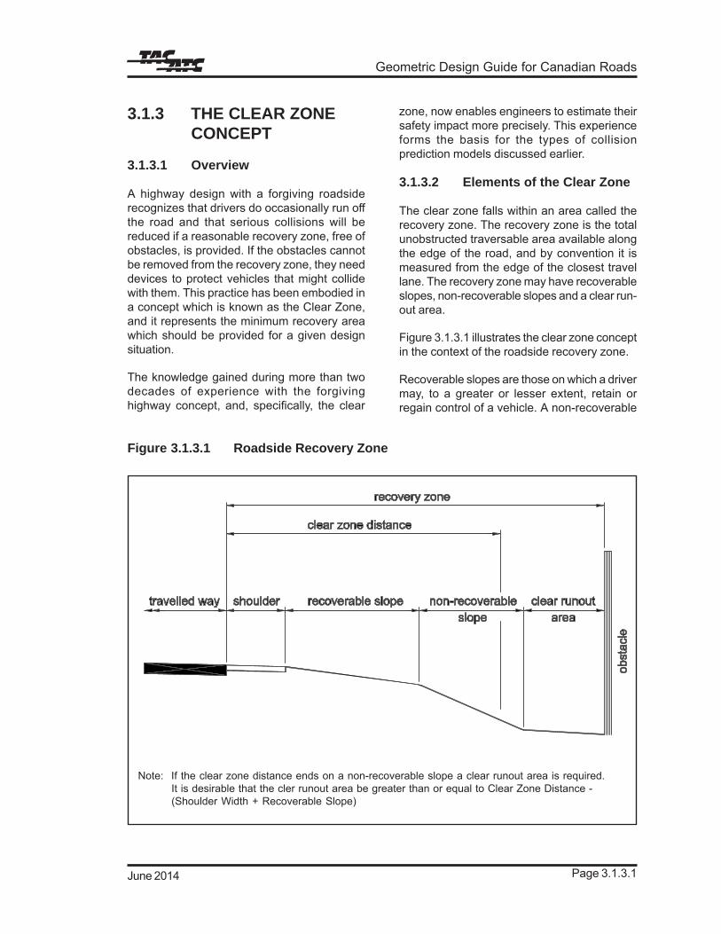
The clear zone falls within an area called therecovery zone. The recovery zone is the totalunobstructed traversable area available alongthe edge of the road, and by convention it ismeasured from the edge of the closest travellane. The recovery zone may have recoverableslopes, non-recoverable slopes and a clear run-out area.
Figure 3.1.3.1 illustrates the clear zone conceptin the context of the roadside recovery zone.
Recoverable slopes are those on which a drivermay, to a greater or lesser extent, retain orregain control of a vehicle. A non-recoverable
Figure 3.1.3.1 Roadside Recovery Zone
Note: If the clear zone distance ends on a non-recoverable slope a clear runout area is required.It is desirable that the cler runout area be greater than or equal to Clear Zone Distance -(Shoulder Width + Recoverable Slope)

Roadside Safety
September 1999Page 3.1.3.2
slope may be traversable, but a vehicle willcontinue to the bottom. A clear runout area islocated at the toe of a non-recoverable slope,and is available for safe use by an errant vehicle.There is also provision for a smooth transitionbetween slopes to allow for the safe passageof vehicles.
The clear zone is the total, fixed-object-free areaavailable to the errant vehicle. The designdomain for the clear zone width has been foundto depend on traffic volume and speed, roadgeometry, embankment height, side slope andenvironmental conditions such as snow, ice,and fog. The wider the clear zone, the less thefrequency and severity of collisions with fixedobjects. However, there is a point beyond whichany further expenditure to move or protect thefixed objects is not warranted because themarginal risk reduction is too small.
3.1.3.3 Factors Influencing theClear Zone Design Domain
When originally introduced, the clear zoneconcept dictated a single value and was basedon limited observations taken from a researchfacility context. The concept was formallyintroduced in the 1974 version of the AASHTOreport entitled Highway Design and OperationalPractices Related to Highway Safety where theauthors noted:
”...for adequate safety, it is desirable to providean unencumbered roadside recovery area thatis as wide as practical on a specific highwaysection. Studies have indicated that on high-speed highways, a width of 9 metres or morefrom the edge of the travelled way permits about80 percent of the vehicles leaving a roadwayout of control to recover…” 7
The last portion of this statement requiresemphasis. Provision of the recommended clearzone does not guarantee that all vehicles willnot encroach further than the recommendedclear zone distance. Quite the contrary, the clearzone principle embodies the explicit fact thatsome substantial portion of the vehicles whichencroach will go beyond the clear zone itself,as illustrated in Figure 3.1.3.2.
Early after its introduction, it became apparentthat a single value of 9.0 m for the clear zonedistance was not always appropriate. Steeperembankment slopes tended to increase vehicleencroachment distances. Conversely, on low-volume or low-speed facilities, the 9.0 mdistance was excessive and could seldom bejustified. As a result, as the concept evolved,design practice moved to a variable clear zonedistance definition and a better understandingof the wide range of factors which influence thelimits of its design domain was gained.
In this Guide, the concepts reflected in the 1996AASHTO Roadside Design Guide have beenretained. Where sound, factual research wasavailable, the application of the concepts hasbeen modified to better conform to Canadianconditions and practice as appropriate. In thiscontext, the clear zone design domain reflectsthe influence of:
• design speed
• traffic volumes
• the presence of cut or fill slopes
• the steepness of slopes
• horizontal curve adjustments
Although a clear and unambiguous guide toappropriate limits to, and adjustments for, thedesign domain of the clear zone is provided inSubsection 3.1.3.4 of this chapter, designersmust recognize the limitations of the underlyingwork which provides the basis for this definition.In discussing the set of curves it uses to defineits variable clear zone recommendations,AASHTO provides a thoughtful caution todesigners:
“…the numbers obtained from these curvesrepresent a reasonable measure of the degreeof safety suggested for a particular roadside;but they are neither absolute nor precise. Insome cases, it is reasonable to leave a fixedobject within the clear zone; in other instances,an object beyond the clear zone distance mayrequire removal or shielding. Use of anappropriate clear zone distance amounts to a

Geometric Design Guide for Canadian Roads
Page 3.3.4.3December 2009
agency normally has specific clearancerequirements which are to be honoured. In manycases, it is desirable to relocate the overheadutility underground to avoid the conflict, whileimproving the aesthetics of the street right ofway.
With respect to street lights, it is desirable toexamine the blocking effect of the future maturetree canopies on the illumination levels intendedfor the roadway and the pedestrian areas.Strategic spacing, consideration of tree canopyform, and pruning of trees relative to theluminaries is often sufficient to avoid significantproblems for the roadway illumination. It isdesirable to position trees midway betweenstreetlight poles and to prune the lower branchesso that unobstructed light reaches a point aminimum of 1.8 m above the mid-span pointsas illustrated on Figure 3.3.4.1.4 It is alsodesirable to select trees with thin, permeablecanopies to reduce the needs of pruning.Separate pedestrian style lighting may berequired to provide the levels of illuminancenecessary for the safety and security of thepedestrian area.
For the climatic conditions in most Canadianurban centres, it is important not to provide adense tree cover adjacent to pedestrian areas.The warmth provided by the sun is generallybeneficial for pedestrian comfort in temperateclimates. The strategic placement of deciduoustrees is effective in providing shade protectionduring hot summer afternoons while allowingthe sun to provide warmth during winter months.
Tree spacing and location are dependent on avariety of factors including:
• desired visual affect
• species of tree
• physical constraints, such as utilities,lighting, and underground structures
• vehicle/vehicle and vehicle/pedestrian sightline requirements
Each streetscaping project is normallyassessed on the basis of the existing conditionsand constraints toward identifying the mosteffective planting plan.
Tree grates are normally provided for trees plantedwithin a hard surfaced pedestrian area. Their usemaximizes the available pedestrian travel spacewhile allowing proper gas exchange at the air/soil contact zone. Tree grates are typicallymanufactured using durable concrete or cast-ironmaterials. It is important to provide surfacedrainage away from the tree trunk to assist inminimizing the intrusion of roadway salt and otherharmful materials into the soil and root system.Raised curbs around each tree pit may beeffective in limiting salt intrusion but are morerestrictive to pedestrian travel than grates whichare flush with adjacent sidewalks. Tree or othergrates not flush with the sidewalk or withopenings greater than 13 mm in diameter maypose a hazard for persons with reduced mobility,and are normally located laterally beyond theline of travel and clear sidewalk width.
Appropriate vegetation can be selected for useon embankment and cut slopes to effectivelycreate soft aesthetics, reduce maintenance andincrease slope stability.
3.3.4.3 Vehicular TrafficConsiderations
The location and configuration of vegetation aredetermined so as to maintain the sight linesrequired at street intersections and otherpedestrian crossing areas. Sight distancerequirements are discussed in Chapter 2.3 -Intersections. Shrubs less than 1.0 m in heightand trees with canopies providing at least 2.4 mof vertical clearance may be considered withinan intersection sight triangle. Hedges, highshrubs and coniferous trees which block sightlines are avoided in these critical areas.Generally, it is desirable to eliminate, or at leastrestrict, the type and amount of vegetation withinthe critical sight triangles at intersection areasto maintain pedestrian and vehicular safety.
The locations of traffic signs, particularlyregulatory and warning signs, and traffic signalsare normally co-ordinated with the planting layout.Vegetation at locations that may block the driver’sview of traffic signs and signals are avoided.
When creating a tree planting plan, consultationwith the adjacent property owners and business
Streetscaping
Page 3.3.4.4 June 2014
operators is desirable. It may be desirable notto block important or interesting buildings fromthe view of the passing vehicular traffic. Certainbuildings may be equally or more important tothe visual quality and character of the street thanplanted vegetation.
Trees with trunk diameters greater than 150 mmat maturity are considered fixed objects. Groupsof small trees or shrubs closely spaced mayhave the same effect as a single large tree.Therefore, for larger trees and tree groups, it isadvisable to locate trees in accordance with theclear zone guidelines, based on design speed,from the edge of the travel lane (existing orfuture) to the tree trunk, as outlined in Chapter3.1. Permitted locations for trees are often amatter of local policy, but it is generally desirableto avoid having large trees in close proximity ofvehicular travel lanes, such as within boulevardsless than 2.0 m and medians less than 4.5 m inwidth. When parking is provided along an urbanstreet where streetscaping is employed, theparking area generally provides a suitable bufferbetween the traffic lanes and the boulevardtrees and other fixed objects, and therefore thecurb to fixed object dimension is less critical.
A minimum setback of 750 mm from the curbface to the tree trunk face is generally desirablein all cases. This provides a suitable minimumclearance for passengers to open a vehicle doorand exit/enter reasonably unimpeded, reducesthe frequency of splashed salt and other harmfulmaterials onto the tree trunk and minimizes theintrusion of root growth into the road subgrade.
3.3.4.4 Roadside Treatments
The selection of the most appropriate roadsidearea treatments is influenced by a number offactors including:
• the total curb to property line (roadside)width available
• the clear sidewalk width required toaccommodate the anticipated pedestriancharacteristics and volumes
• the nature and characteristics of theadjacent land use
• the volume, speed and type of vehiculartraffic along the adjacent roadway
• the location of overhead and undergroundutilities
Generally, four options are available to thedesigner as illustrated in Figure 3.3.4.2.5 Eachlandscaping project is assessed on its individualcharacteristics. It may be advantageous oncertain projects to implement combinations ofoptions to suit varying land uses, vehicular trafficand parking conditions, and the physicalconstraints; combination of options may bemore visually stimulating in making themotorists more aware of the drivingenvironment and thus enhancing safety. Wherea change is made from one option to another, itis important to design the pedestrian routetransitions to be obvious and unobstructed.
A description and typical application of the fouroptions are outlined by the following:
Option A – Boulevard and Border VerticalFeatures
This treatment is particularly beneficial wherewide expanses of paved areas exist on eitherside of the roadside. An example is a pedestrianarea between a multi-lane road and a parkingarea for a regional shopping centre. The verticalfeatures and the created enclosure effectivelybuffer the pedestrian from both the busy roadand the adjacent land use. To provide anappropriate pedestrian scale, the ratio ofpedestrian area width to height of the verticalfeatures is normally in the range of 1:1 to 1:2.
Option B – Border Vertical Features Only
With this option, a buffer is introduced onlybetween the pedestrian area and the adjacentdevelopment and therefore provides a physicalseparation between the pedestrian area and theadjacent land uses. Common applications arealong off-street parking areas and adjacent toindustrial land uses, where large and unsightlyareas are visible to the pedestrian. Theaesthetics of residential land uses may also beimproved by this style of treatment. Thisarrangement may also be the only feasible option

Geometric Design Guide for Canadian Roads
Page 3.3.4.5September 1999
Figure 3.3.4.2 Roadside Streetscaping Alternatives5

Streetscaping
Page 3.3.4.6 June 2014
where overhead utility lines exist along theroadway curb and the width of the roadsideprecludes Option C. If there is a high level ofmovement between a roadway parking laneand the pedestrian area, or where futureroadway widening is planned, Option B maybe advantageous. This option also provides thebest visibility, between the vehicle driver andthe pedestrian, where pedestrians are expectedto cross the roadway.
Option C – Vertical Features Centre ofRoadside
The most common use of this concept is alonga street with relatively tall buildings and busycommercial activity at street level. The verticalfeatures help to scale down the adjacentbuildings to the pedestrian level. The centrefeatures create separate pedestrian areasalong the adjacent commercial space and alongthe curb. This treatment is beneficial whereon-street parking to sidewalk activity level isexpected to be high, and can be used effectivelywhere future roadway widening is planned. Theminimum total roadside width is normally 6.0m for this option to be functional.
Option D – Boulevard Vertical Features Only
This option is generally used where there is aneed to buffer the pedestrian area from a busyroadway. The adjacent land use is typically suchthat a continuous exposure from the pedestrianarea is desirable or at least not objectionable.Examples of such land uses are continuousretail spaces with display windows or aninteresting park space or recreational activityarea. The vertical features adjacent to theroadway are normally positioned in accordancewith the clear zone guidelines provided inChapter 3.1.
In commercial areas, it is common practice forthe entire roadside width to be hard surfaced,from the curb to the right-of-way limit, and oftenbeyond, where buildings are set back from theproperty line. Narrow grass strips in commercialareas are costly to maintain and are subject todamage from sand and salt intrusion, snowremoval, and pedestrian and bicycle traffic.
A number of different materials, includingconcrete, impressed concrete, asphalt, concretepavers, brick, stone, and asphalt pavers, canbe used effectively to hard surface the boulevardand border areas. For a streetscaped roadside,it is generally preferable to use plain materials,such as concrete or asphalt, for the boulevardand border areas. Decorative materials, such asconcrete pavers and brick, are most effectivelyused to delineate the edge of pedestrian area orwithin the pedestrian area to provide routecontinuity and to enhance the pleasure of, andinterest in, walking along the street.
3.3.4.5 Median and OuterSeparation Treatments
Narrow medians and outer separations, 2.0 mor less in width, are normally hard surfaced dueto the difficulty in maintaining narrow strips ofgrass. Concrete or asphalt materials aretypically used to surface the narrow median orouter separation areas. The use of decorativematerials, such as concrete pavers, stone orbrick, for median and outer separation areas isgenerally of less benefit as compared toroadside treatments. Pedestrians areappreciative of the decorative detail andtherefore, if funds are limited, it is usually morecost-effective to use these materials in thepedestrian areas rather than the median andouter separation areas. However, decorativemedians and outer separations are of visualbenefit to passing motor vehicle occupants,cyclists and adjacent property owners andbusinesses.
For medians and outer separationsapproximately 2.0 m to 4.5 m in width, grass istypically the most common surface treatment.Where these cross section elements are widerthan 4.5 m, the use of shrubs and trees,together with grass, are common landscapetreatments. In the vicinity of intersections orpedestrian crossings, it is important to keep thesight triangles free of obstructions. Low shrubs,less than 1.0 m in height, and trees with highcanopies, providing more than 2.4 m of verticalclearance, can often be used withoutsignificantly interfering with sight lines. Potentialproblems with street lights should be avoidedas discussed in Subsection 3.3.4.2.

Geometric Design Guide for Canadian Roads
Page 3.4.5.1December 2009
3.4.5 ALIGNMENTELEMENTS
The alignment elements in the followingparagraphs are generally applicable to bikepaths. Other classifications of bikeways aredesigned for motor vehicle traffic and thosestandards are adequate for bicycles, with theexception of stopping sight distance. Stoppingsight distance is greater for bicycles than motorvehicles, particularly in the case of steepdowngrades, and should be considered in thedesignation of bike lanes and bike routes.
3.4.5.1 General Approach
As for any transportation facility, there is aresponsibility to generate a collision free design.The standards and practices for bikeways thatfollow are intended to assist designers to meetthis responsibility. However, the bicycle is adistinct vehicle which is often used in locationsof substandard geometrics. In such cases,providing suitable warning signs along bikewaysis a significant consideration in maintainingsafety.
3.4.5.2 Design Vehicles
The suggested dimensions of a bicycle to beused in the design of bikeways are:
• length, 1.75 m
• width at pedals, 400 mm
• height to lowest pedal position, 100 mm
• width at handlebars, 800 mm
• height to handlebars, 1.25 m
• height to top of seated riders, 2.0 m
Desirable bikeway widths for design are asfollows:
• one-way, 1.20 m to 1.60 m
• two-way, 2.20 m to 2.60 m
3.4.5.3 Design Speed
The speed at which a cyclist travels is dependenton several factors, including the type andcondition of the bicycle, the purpose of the trip,the condition and location of the path, the speedand direction of the wind, and the physicalcondition of the cyclist. Paved bike paths aredesigned for a selected speed that is at leastas high as the preferred speed of the fastercyclists. In general, a minimum design speedof 30 km/h is used; however, when thedowngrade exceeds 4%, or if strong tailwindsprevail, a design speed of 50 km/h is advisable.
On unpaved paths, where cyclists tend to ridemore slowly, a lower design speed of 25 km/hcan be used or where the grades or theprevailing winds dictate, a higher design speedof 40 km/h can be used. Since bicycles have ahigher tendency to skid on unpaved surfaces,horizontal curvature design should take intoaccount lower coefficients of friction.
3.4.5.4 Stopping Sight Distance
Minimum stopping sight distance for bicyclesis the distance required to bring a bicycle to acontrolled full stop. It is a function of the cyclists’perception and brake reaction time, the initialspeed of the bicycle, the coefficient of frictionbetween the tires and the bikeway surface andthe braking capability of the bicycle. Thestopping sight distance is given by theexpression:
(3.4.1)
Where: SSD = stopping sight distance (m)
V = design speed (km/h)
f = coefficient of friction
G = grade (% up grade is positiveand down grade is negative)
The expression is based on a perception-reactiontime of 2.5 s. Table 3.4.5.1 illustrates minimumstopping sight distance for a range of speedsfrom 10 to 50 km/h and grades up to 12%. For
)100/gf(255VV694.0SSD
2
++=

Bikeways
Page 3.4.5.2 June 2014
two-way facilities, the values for the descendingdirection control the design. Coefficient of friction(f) is taken to be 0.25 for paved surfaces, which
accounts for the poor wet weather brakingcharacteristics of many bicycles.2
Table 3.4.5.1 Minimum Stopping Sight Distance for Bicycles(Paved Surface, Wet Conditions)
3.4.5.5 Horizontal Alignment
Radius and Superelevation
The minimum radius of a circular curve for abikeway is a function of bicycle speed,superelevation, and coefficient of friction. Thesevariables are related by the expression:
(3.4.2)
Where: R = radius (m)
V = design speed (km/h)
e = superelevation (m/m)
f = coefficient of lateral friction
This relationship is used to determine theminimum design radius for given designspeeds. For most applications and conditions,the superelevation rate will range from aminimum of 0.02 to 0.05 m/m. The coefficientof lateral friction used for design of pavedbikeways varies from 0.3 at 25 km/h to 0.22 at50 km/h. For the design of unpaved surfaces,lateral friction factors are reduced to 50% ofthose of paved surfaces. Table 3.4.5.2 givescoefficient of lateral friction and minimum radiusfor a range of design speeds based onsuperelevation rates of 0.02 and 0.05 m/m.
Where curve radii less than those inTable 3.4.5.2 are used, or superelevation isunavailable, warning signs in advance of thecurve are appropriate.
Lateral Clearance on Horizontal Curves
Lateral clearance to obstructions on the insideof horizontal curves is based on the need to
)fe(127VR
2
+=
Minimum Stopping Sight Distance (m)Design Speed (km/h)Grade
(%) 10 15 20 25 30 35 40 45 50121086420-2-4-6-8-10-12
888888999991010
13131313131414141515161617
18181919192020212122232426
-242525262627282930323436
--
3232333435363839424448
---
40414244454750535361
----
495153555861657076
-----
6163666973688492
------
7477818692100110
Notes: For the purposes of measuring stopping sight distance the height of eye is normally taken to be1.37 m and the height of object zero, to provide for impediments to bicycles at pavement level,such as potholes.For selection of design speed, refer to Subsection 3.4.5.3.