To Draft or Not to Draft. Sections and Elevations …...To Draft or Not to Draft. Sections and...
8
December 2-5, 2003 ◊ MGM Grand Hotel Las Vegas To Draft or Not to Draft. Sections and Elevations with Autodesk Architectural Desktop Troy Mifsud Code BD43-3 Autodesk® Architectural Desktop 2004 has greatly improved the tools to help you create sections and elevations for your buildings. In this class, we'll review the process and weigh the pros and cons of generating your sections and elevations from a model. About the Speaker: Troy has many years of experience as a CAD manager and architectural designer on healthcare and education projects. He was a former architectural application engineer for a major Autodesk® reseller in Boston, where he implemented Autodesk® Architectural Desktop, developed CAD standards, and trained and supported architectural staff for numerous clients. Troy specializes in implementation and standardization of AutoCAD® and Architectural Desktop. He earned a Bachelor of Architectural Technology Degree from Ryerson University in Toronto. [email protected]
Transcript of To Draft or Not to Draft. Sections and Elevations …...To Draft or Not to Draft. Sections and...
December 2-5, 2003 ◊ MGM Grand Hotel Las Vegas
To Draft or Not to Draft.
Sections and Elevations with Autodesk Architectural Desktop Troy Mifsud
Code BD43-3
Autodesk® Architectural Desktop 2004 has greatly improved the tools to help you create sections and elevations for your buildings. In this class, we'll review the process and weigh the pros and cons of generating your sections and elevations from a model.
About the Speaker:
Troy has many years of experience as a CAD manager and architectural designer on healthcare and education projects. He was a former architectural application engineer for a major Autodesk® reseller in Boston, where he implemented Autodesk® Architectural Desktop, developed CAD standards, and trained and supported architectural staff for numerous clients. Troy specializes in implementation and standardization of AutoCAD® and Architectural Desktop. He earned a Bachelor of Architectural Technology Degree from Ryerson University in Toronto.

To Draft or Not to Draft. Sections & Elevations with ADT 2004.
2
GOAL OF THIS SESSION The goal of this work shop is to help you evaluate if creating sections and elevations from your model is appropriate for your office and to show you how you to set up section and elevation styles. TOOLS DISCUSSED
Switching views and shading Hidden Line Projections 2D Section/Elevation Objects Materials WAYS TO CREATE ELEVATIONS/SECTIONS
There are essentially 3 ways to create elevations/sections from your building model.
Method 1 –Live Views of 3D model. Simply use view toolbar to switch from one viewpoint to another. Use shade toolbar to change to hidden line view of model. For sections there is a special method view called a live section view.
Method 2 – Hidden Line Projections – Once you are looking at the elevation in the 3D view you can extract a 2D line drawing. You can then colorize the elevation with solid fill and gradient hatches. Advantage is this is easy to do. Disadvantage is that linework may require significant cleanup and any time the model changes you must recreate the 2D elevation.
Method 3 – Create a Section/Elevation Object which is a 2D drawing which is linked to the model. Advantages over Method 2 are if model changes you can simply refresh the elevation and you can create section/elevation styles which contain rules to help you control the lineweights.
To Draft or Not to Draft. Sections and Elevations with ADT 2004.
3
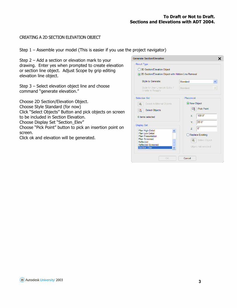
CREATING A 2D SECTION ELEVATION OBJECT
Step 1 – Assemble your model (This is easier if you use the project navigator) Step 2 – Add a section or elevation mark to your drawing. Enter yes when prompted to create elevation or section line object. Adjust Scope by grip editing elevation line object. Step 3 – Select elevation object line and choose command “generate elevation.” Choose 2D Section/Elevation Object. Choose Style Standard (for now) Click “Select Objects” Button and pick objects on screen to be included in Section Elevation. Choose Display Set “Section_Elev” Choose “Pick Point” button to pick an insertion point on screen. Click ok and elevation will be generated.

To Draft or Not to Draft. Sections & Elevations with ADT 2004.
4
Understanding Section/Elevation Object
The Elevation/Section object that we just created is certainly not suitable for construction documentation at this stage, but by making adjustment to the style, or creating new styles we can achieve the results we are looking for.
The Defining Line, Outer Shrinkwrap and Inner Shrinkwrap are only displayed in Section views as they occur at the cut line. Hidden – move objects that you want to display as hidden lines to this component (ie. Door swings and lines of foundation wall below grade) Erased – this component is typically turned off (it is turned on in the sketch above for illustration purposes). Moving lines to this component typically has the same effect as erasing the lines. Subdivisions 1-10 – represent color ranges and therefore lineweight ranges. This is typically used for elevations to allow you to have thinner lines on surfaces in the distance. For more information about the “By Material” check box see page 7. DESIGN RULES
Design Rules allow you to control color and lineweight of all objects in your elevation. By establishing design rules you can avoid the tedious task of editing linework. Basically, you establish a rule which says if the color of the object in the 3D model is “xxxx” then change it to a specified component in the elevation object.

To Draft or Not to Draft. Sections and Elevations with ADT 2004.
5
DRAWING ADDITIONAL LINEWORK There are two ways to create all the additional linework which would be required for a construction document quality elevation or section. You can draw additional lines over top the elevation/section object or you can continue to build your model. While it may be easier and quicker to draw over top the first time I feel that it is possible to be more productive if you continue to “model” the building. If you choose to draft the elevation any changes to the design will you require to redraft the additional linework. If you model the changes any change will be integrated immediately. In addition, if you take advantage of “styles” in your drawing it may actually be quicker to model your building than draw it. DRAWING, MERGING AND EDITING LINEWORK When you draw additional linework you have the option of merging the linework into the 2D elevation. You also have the ability to change which component any line resides on. I think you are better off drawing lines on an appropriate layer rather than merging for several reasons; Any changes to the model affecting the areas where you’ve merged lines will probably not be reapplied appropriately. Any changes to the model affecting the areas where you’ve editing lines will probably not be reapplied appropriately It is easier to edit the linework if it is not merged. To access the commands select the elevation/section object, right click go to the linework section and choose edit or merge. If you choose edit any surface/section hatch will temporarily disappear while editing. They will reappear when you exit edit-in-place editing mode. Note: Be sure to remember to save the edits by exiting out of edit-in-place mode. To exit from edit in place mode select any line which is part of the elevation, right click and go to edit-in-place and choose either save or discard changes. MODELING VS. DRAFTING While generating a simple elevation from a simple model and adding linework overtop may be an easy way to generate elevations/sections, I think you can be more productive if you continue to model your building in more detail. Of course, the better you are at modeling with architectural desktop, the better your elevations/sections and the more productive you will be. With that said I don’t think you have to be a guru with ADT to get good results. If you understand how to make changes styles you make quick global changes you will be able to explore design alternatives quickly. If your staff can master walls, doors, windows styles you will be able to get good results. If your staff can master curtain walls, window assemblies and roofs you will do well. If you master using massing elements for modeling other complex geometry you will do great!

To Draft or Not to Draft. Sections & Elevations with ADT 2004.
6
MATERIALS
Materials allow you to add surface and section hatches to your elevations/sections. Materials can also allow you to control the linework and hatches in plan but I prefer to only use materials for sections and elevations. Plan Linework/Hatch – These are the lines and hatch for components in the plan view (ie wall components, door and window frames). I prefer not to use plan hatch and plan linework as I had already established standards in the previous release and don’t see benefits to changing. 2D Section/Elevation Linework – Even though the name says section/elevation linework this really only affects the color of linework in the elevations. 3D Body – This is the color of lines of component in 3d View. This color will only be visible if you apply a material to an object and specify that the material is controlling the appearance of the object. Design Rules reference this color. Surface/Section Hatches – This controls the color, layer, linetype, hatch pattern for hatches in 3d live section and 2d sections. Sectioned Boundary – This is the boundary of the components in the live section view. Sectioned Body – The is the portion of the building which is cut away by the live section view. WHO’S THE BOSS – MATERIALS OR STYLES? When you create any style, whether it be a 2d elevation/section style, wall style or door style you get to choose which settings govern. By selecting the “By Material” checkbox you are saying that the settings established in the material are controlling the appearance of the object. Refer to the graphic on page 4 for elevation/section style. The settings in their indicate that the color of the hatches displayed in the end result are the colors as specified in the material.

To Draft or Not to Draft. Sections and Elevations with ADT 2004.
7
CREATING AN ELEVATION STYLE FOR CONSTRUCTION DOCUMENTS
Step 1 – Learn what controls the color of each object in the elevation. When you generate the Section/Elevation you select the Display Set to use. Always choose “Section_Elev”. This means you are using the view of the object identified in the “Section_Elev” Representation Set to control the color of the object.
The “Section_Elev” representation set uses the model view of all objects… except for doors, windows and structural members where it uses the “elevation” view for those objects.
Step 2 – Create the new 2D Section Elevation Style – Go to the Style manager and create a new style called “Elevation-CD”
To Draft or Not to Draft. Sections & Elevations with ADT 2004.
8
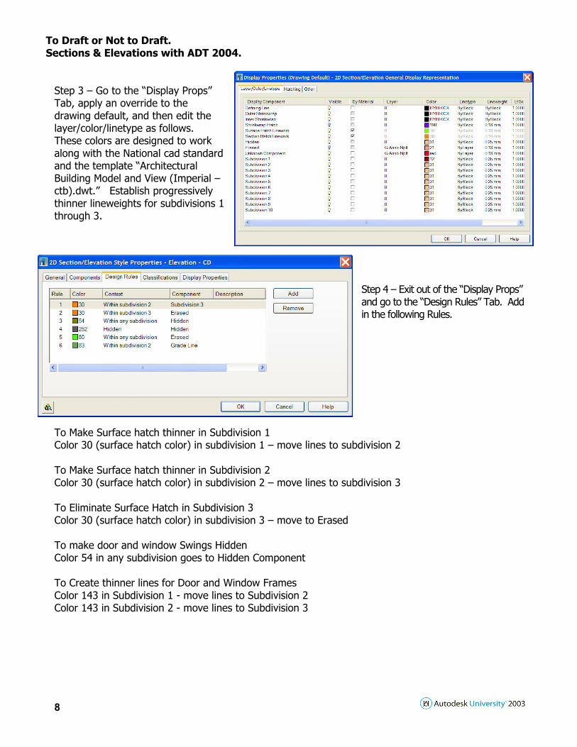
Step 3 – Go to the “Display Props” Tab, apply an override to the drawing default, and then edit the layer/color/linetype as follows. These colors are designed to work along with the National cad standard and the template “Architectural Building Model and View (Imperial – ctb).dwt.” Establish progressively thinner lineweights for subdivisions 1 through 3.
Step 4 – Exit out of the “Display Props” and go to the “Design Rules” Tab. Add in the following Rules.
To Make Surface hatch thinner in Subdivision 1 Color 30 (surface hatch color) in subdivision 1 – move lines to subdivision 2 To Make Surface hatch thinner in Subdivision 2 Color 30 (surface hatch color) in subdivision 2 – move lines to subdivision 3 To Eliminate Surface Hatch in Subdivision 3 Color 30 (surface hatch color) in subdivision 3 – move to Erased To make door and window Swings Hidden Color 54 in any subdivision goes to Hidden Component To Create thinner lines for Door and Window Frames Color 143 in Subdivision 1 - move lines to Subdivision 2 Color 143 in Subdivision 2 - move lines to Subdivision 3