TO - Defense Technical Information Center RETRACTABLE HOOK-CABLE SUPPORT SYSTEM Final, 15-20 January...
51
UNCLASSIFIED AD NUMBER AD922523 NEW LIMITATION CHANGE TO Approved for public release, distribution unlimited FROM Distribution authorized to U.S. Gov't. agencies only; Administrative/Operational Use; 27 AUG 1974. Other requests shall be referred to Naval Air Test Facility, Lakehurst, NJ 08733. AUTHORITY NATF ltr, 23 Jun 1976 THIS PAGE IS UNCLASSIFIED
Transcript of TO - Defense Technical Information Center RETRACTABLE HOOK-CABLE SUPPORT SYSTEM Final, 15-20 January...

UNCLASSIFIED
AD NUMBER
AD922523
NEW LIMITATION CHANGE
TOApproved for public release, distributionunlimited
FROMDistribution authorized to U.S. Gov't.agencies only; Administrative/OperationalUse; 27 AUG 1974. Other requests shall bereferred to Naval Air Test Facility,Lakehurst, NJ 08733.
AUTHORITY
NATF ltr, 23 Jun 1976
THIS PAGE IS UNCLASSIFIED

THIS REPORT HAS BEEN DELIMITED
AND CLEARED FOR PUBLIC RELEASE
UNDER DOD DIRECTIVE 5200,20 AND
NO RESTRICTIONS ARE IMPOSED UPON /-
ITS USE AND DISCLOSURE, :
DISTRIBUTION STATEMENT A
APPROVED FOR PUBLIC RELEASE;
DISTRIBUTION UNLIMITED$
TI,
Laehrvie Jersey -
-BAK-1-4~ ~~~~~~,~ RETATB- HO-CESPOTSSE
CODWAHR ET A NtA'AAK
Lokaust Newhusf NewJese 073
Wald Rpotfo erar Watrog 20 4anu
Decotry ibusion, nineerin DoUS.oeprtment
OfieNaval Air Test Facility, ae
Nava ava Ai ngnir v tein tePhLaerst, Pa. Je9ey1873
4

BestAvailable
Copy

4, ,
- ~~Prepared-'by: %/4 qe. (
-- R a &d6mar Wdsta116
Rev~wed y:kead ecoveryDivision
-~ ;pproved by:t * *K'acz -
-Superintendent I rEngineering,
J, -
-
LI
- - .- <.- i -- ',_,x - '-. - .
#4
IJNGLIASS 11- 1 E1)S URITY CLASSIFICATION OF THI
- PAGE (When Date Entered)
READ INSTRUCTIONSREPORT DOCUMENTATION PAGE BEFORE COMPLETING FORM
I. REPORT NUMBER 2. GOVT ACCESSION NO. 3. RECIPIENT'S CATALOG NUMBER
NATF-EN-1132 ___ ___ ___
) 4. TITLE (and Subtitle) 5. TYPE OF REPORT & PERIOD COVERED
BAK-14 RETRACTABLE HOOK-CABLE SUPPORT SYSTEM Final, 15-20 January 1974COLD-WEATHER TESTS AT GALENA, ALASKA1z'. 6. PERFO)RMING ORG. REPORT NUMBER
7. AUTHOR(e) 8. CONTRACTOR GRANT NUMBER(e)
Waldemar Wastallo
9 PERFORMING ORGANIZATION NAME AND ADDRESS 10. PROGRAM ELEMEt:T. PROJECT. TASKAREA & WORK UNIT NUMBERS
Naval Air Test Facility (4210) (98, 0068, 001, 00)Naval Air Station NAVAIRENGCEN Project OrderLakehurst. N.J. 08733 4-4027
S •II. CONTROLLING OFFICE NAME AND ADDRESS 12. REPORT DATE
Commanding Officer 27 August 1974Naval Air Engineering Center 13. NUMBER OF PAGES
Philadelphia, Pa. 19112 44-14 MONITORING AGENCY NAME & ADDRESS(If different from Controllln OfIce) 15. SECURITY CLASS. (of Clhi 'iAort)
J +UNCLASSIFIED
I++} SCHEDULE+. ,JOCE i 5.D ASSI FICATION/13OWNGRADIN G
16. DISTRIBUTION STATEMENT (of this Report)f Distribution limited to U.S. Government agencies only; proprietary informa-
tion; 28 January 1974. Other requests for this document must be referredSto Commanding Officer, Naval Air Test Facility, Lakehurst, N.J. 08733
ATTN: Code 4000
A 17. DISTRIBUTION STATEMENT (of the abstract entered In Block 20, If different from Report)
.S 18. SUPPLEMENTARY NOTES
EY. WORDS (Continue on reverse. side I necesary and Identify by block nmber)BAK-14 COLD-WEATHER TESTS 47 i'1?4
BAK-14 RETRACTABLE HOOK-CABLE SUPPORT SYSTEM -- " -.-:, ,,
HOOK-CABLE SUPPORTS V 1 ,-- iSHOREBASED AIRCRAFT ARRESTING GEAR/SYSTEM 'i2U
20. ABSTRACT (Continue on revete side If necessary aid Identify by block numb.r)
+'q +'The BAK-14 retractable hook-cable support system was designed for ut. e with air-craft arresting systems on Air Force/Civil joint-use airfields. In the raised
position, the BAK-14 supports the aircraft arresting-hook cable above the run-way surface for engagement of arresting-hook-equipped aircraft; in the lowered
I-position, the runway surface is clear and the BAK-14 offers no interference tothe operation of lightweight civil aircraft. These tests were conducted to
Continued on next page.'I /,, FORM-
DD I JAN 73 1473 EDITION OF I NOV 65 IS OBSOLETE UNC..SSIFIEDS/N 0102-014-6601 I nDtEneeSIN 102-14-601 1SECURITY CLASSIFICATION OF TNIS PAGE (Whien Data Entered)
A--
== - - " -

11NCTATFTEn -.,LCURITY CLASSIFICATION OF THIS PAGEO4ien Dat Cnieed)
Z- BLOCK 20 CONTINUED
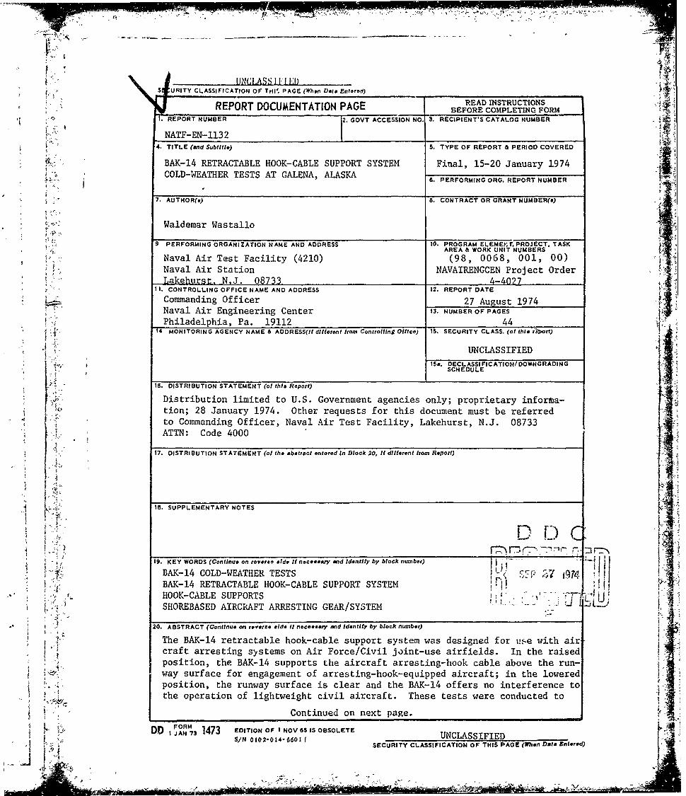
determine the effects of natural low-temperature conditions on the functionaland dynamic operation of the BAK-14. The areas of special interest were theability of the support block to withstand aircraft main-gear trample andarresting-hook impact, and the ability of the system to cycle 100 times.Tramples and arrestments were conducted with the F-4E aircraft under -150 Fto -24* F ambient temperature conditions. The system sustained negligibledamage from the aircraft tramples, but was inoperable as a result of thecumulative damage caused by the six arrestments. Under the low ambient tern-peratures, the supports were not pliable. All 14 blocks of the system werepartially to fully separated from their bases. Support-block latch mecha-nisms were damaged. The 100-cycle test was completed under -33* F to -360 Fambient temperatures. During this test, several support latch mechanisms mal-functioned and required adjustment. Test results indicated that the BAK-14is not suitable for operation at low ambient temperatures.
-'
if ai
Li:4~.-
-:f - ,
..... ~ ~~~~SECURITY CLA SFCATION OF THIS PAGE(hen D==,AEnterd) r' J
........ .... .. LASSIFIED_
MI
NATF-EN-1132
TABLE OF CONTENTS
SECTION SUBJ.1ECT PAGE
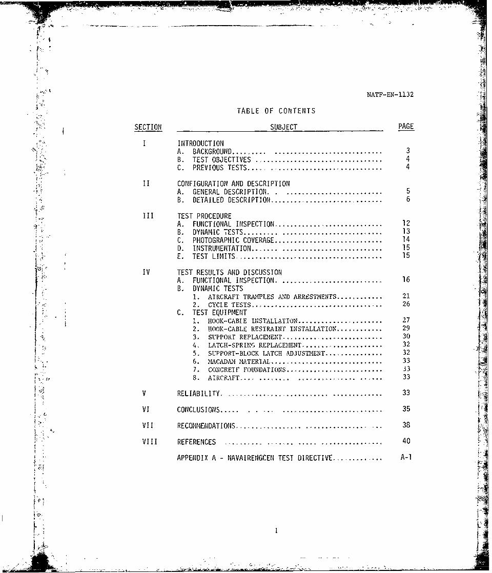
I INTRODUCTIONA. BACKGROUND.... .... ............................ 3B. TEST OBJECTIVES ................................. 4C. PREVIOUS TESTS.... .............................. 4
ii CONFIGURATION AND DESCRIPTIONA. GENERAL DESCRIPTION. ............................ 5B. DETAILED DESCRIPTION......... ............ ....... 6
III TEST PROCEDUREA. FUNCTIONAL INSPECTION............................ 12B. DYNAMIC TESTS ...... .. .......................... 13C. PHOTOGRAPHIC COVERAGE............................ 14D. INSTRUMENTATION....... .......................... 15
E. TEST LIMITS........ ............................. 15
A. FUNCTIONAL INSPECTION ........................... 16 Ti.1B. DYNAMIC TESTS
1. AIRCRAFT TRA14PLES AND ARREIMTENTS ............... 212. CYCLE TESTS ..................................... 26
C. TEST EQUIPMENT1.HOOK-CABLE INSTALL.ATION ......................... 27 i
2. HOO0K-CABLE RESTRAINT INSTALLATION ............... 293. SUPPORr REPLACEMEN.............. ................ 30
4. LATCH-SPRING REPLACEIIENT. ... .................. 325. SUPPORT-BLOCK LATCH ADJUSTMENT..................326. -1ACkDtN MATERIAL ................................ 337. CONCRETE FOUNDATIONS ............... ............ 338. AIRCRAFT. ... .............................. 3
V RELIABILITY ........................... ............. 33
2VI CONCLUSIONS....... ............................. 35
VII RECOMMENDATIONS ................. ................ ... 38
Vill REFERENCES............. ........... ............ ... 40
APPENDIX A -NAVAIRENGOEN TEST DIRECTIVE.... ..... ..... A-i 1- a
_X'
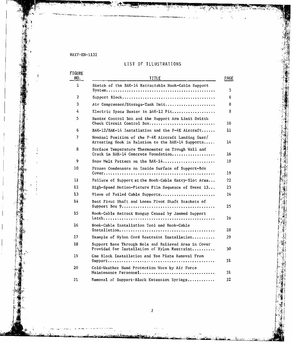
NATF-EN-I132 <A'LIST OF ILLUSTRATIONS
~~FIGURE-'FENO. TITLE PAGE
Sc1 Sketch of the BAK-14 Retractable Hook-Cable SupportSystem ................................................ 5
2 Support Block ......................................... 6
3 Air Compressor/Storage-Tank Unit ....................... 8
4 Electric Space Heater in BAK-12 Pit .................... 8 45 Heater Control Box and the Support Arm Limit Switch
Check Circuit Control Box ............................. 10
6 BAK-12/BAK-14 Installation and the F-4E Aircraft ...... 11
7 Nominal Position of the F-4E Aircraft Landing Gear/ Arresting Hook in Relation to the BAK-14 Supports..... 14
8 Surface Temperature Thermometer on Trough Wall and jtzCrack in BAK-14 Concrete Foundation ................... 16
9 Snow Melt Pattern on the BAK-14 ....................... 19 j10 Frozen Condensate on Inside Surface of Support-Box
Cover ................................................. 19
11 Failure of Support at the Hook-Cable Entry-Slot Area... 22
i 12 High-Speed Motion-Picture Film Sequence of Event 13... 2313 Views of Failed Cable Supports ........................ 24
14 Bent Pivot Shaft and Loose Pivot Shaft Brackets of
Support Box 9 ......................................... 25.J_ 15 Hook-Cable Retract Hangup Caused by Jammed Support
Latch ............................. .......... .......... 26
16 Hook-Cable Installation Tool and Hook-CableInstallation .......................... .......... ...... 28
17 Example of Nylon Cord Restraint Installation .......... 29
18 Support Base Through Hole and Relieved Area in Cover1Provided for Installation of Nylon Restraint .......... 30
19 Cam Block Installation and Toe Plate Removal From-4- . Support .......... ................... ................. 31 -
20 Cold-Weather Hand Protection Worn by Air ForceMaintenance Personnel ............................ ..... 31
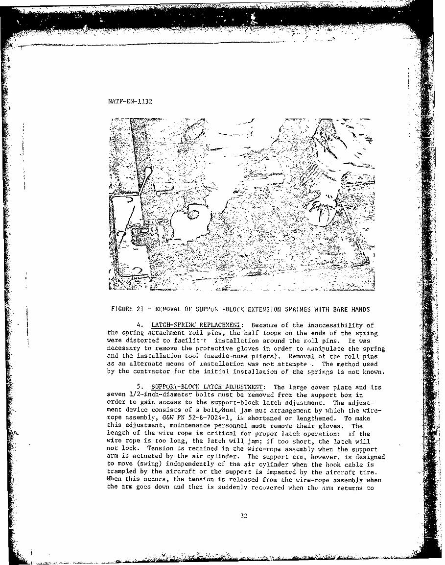
21 Removal of Support-Block Extension Springs ............ 32
2j -
NATF-lMN-I 1132
I INTRODUCTION
A. BACKGROUND
1. The BAK-14 retractable hook-cable oupport system is designedtor uti, with aircraft arrenting tiyatems to satisfy the requirements of'iilitary and civil airc'.aft operations (in Air Force/Civil joint-use air-field runwaiys. The uystem Is capable of raising the arresting-systemhook cable above the runway surface for the engagement of hook-equippedaircraft, and of lowering the hook cable below the runway surfaceto pre-vent interference and damage during rollover of lightweight aircraft(rollover iv dof.ino, n,,y tr.vcr,, lnwcrod/'ctractad hook cable).
2. This test program was conducted to determine the effects ofnatural low-temperature conditions on the functional and dynamic opera-tion of the IIAK-14 retractable hook-cable support system. It was neces-Nary to obtain this information in order to evaluate the suitability ofthe system for eventual operational use in Alaska.
3. The Air Force/Civil joint-use airfield at Galena, Alaska, wasHeclated by the Air Force for the initial installation and test of theIIAK-14 in that State. The Galena airfield test-site location was selectedbecause of the local requirement for the oystem and the low-temperatureclimatic conditions which are typical. in Alaska and necessary for thetests. The Air Force contractor installed the BAK-14 at Galena in Sep-tember 1973. Air Force arresting-system personnel maintained the systemon inactive status until. the start of these tests.
4. The test program was conducted for the Air Force by the Navytett team in accordance with reference (a) on the main runway of the Stateof Alaska Airport, Galena, Alaska, from 15 to 20 January 1974. It con-sinted of two parts as follows:
a. A functional .nspection to assure the system wasready for teut.
b. A dynamic test, using the BAK-12 aircraft arresting sys-tem, which consisted of F-4E aircraft tramples and arreatments, and 100consecutive cyclen of the BAK-1.4 1ystem (trampio Is defined as to traversea rained and tonsionod hook cable).
5. Because of' the limited time available, no attempt was made toconduct these teste under specific temperature or weather conditions fordata purposes. The weather conditions existing at Galena during the pe-riod scheduled for the tests were accepted. The results of these testsare presented in this report.
Ret: (n7 NAVAIRSYSCOM mug 022118Z Jnn 1974: Cold Weather Testing ofJBAK-14 Galena Alaska
-NATF- EN- I Is2
B. TEST OBJECTIVES: The areai of fieeif.ic Intarent and for evaJlia-tion of the BAK-1.4 under Iow-temperature condi.tionij were ao follows:
I. The ability of the uupport blockH to withotand trampling ;)ythe aircraft main gear and impact with the aircraft arresting hook.
2. rhe ability of the tyntem to cycle 100 times.
3. The timc required to raise and lower the system.
4. Posnilble problems involved with installing the hook ci;ble Inthe aupport blockv; tying the hook cable to the support blocks; replacingthe support blocks; and adjusting the support-block latches.
C. PREVIOUS TESTS
1. The test and evaluatLon of several retractable hook-cables1iport systems, including the BAK-14 retractable hook-cable supportprototype (Thurston-Erlandsen Corporation hook-cable support assembly)design and the early BAK-14 retractable hook-cable support system designs,is described in references (b) and (c) respectively.
2. Reference (d) describes the extent of the development effortwhich preceded the reference (e) tests In which the Air Force acceptancerequirement for the BAK-.14 of 76 conqecutfvo successful engagements wasre a azed.
R ef: (b) NAVAIRTESTFAC Report No. NATl'-EI-108 of 31 Aug 1964: EvaIia-tion of Retractable Pendant Supports for the Federal Aviatiu;iAgency
(c) Air Force Systems Command, Aeronautica' . Systems Division, Tech-nical Report No. ASD-TR-69-9 of Aug 1969: BAK-14/F32 Retract-able Cablc Support System
(d) Air Force Systems Command, Air Force Plight Test Center, Tech-nical Report No. FTC-TR-72-41 of Mar 1973: Testing of theBAK-14 Retractable Cable Support System
(e) NNVAIRTESTFAC Report No. NATF-EN-1128 of 22 Jan 1974t Evalua-tion of the BAK-14 Retractable Ilook-Cable Support System
'4

NATF-EN-1132 ,"
II CONFIGURATION AND DESCRIPTION E
A. GENERAL DESCRIPTION ,
1. The BAK-14 hook-cable support system consists of rubber blockswhich support and restrain the hook cable of the aircraft arresting systemapproximately 3 inches above the surface of the runway. 41,
covred2. Each support block is mounted oil a support arm contained in a
covered metal box inserted in the runway. A steel trough is provided in therunway to accept the hook cable. Retraction of the support arm moves the
support block down into the metal box and Lihe hook cable into the metalbox/stecl trough. Thus, a flush runway surface is obtained when the sys-tem is lowered.
3. Retraction of the hook cable is accomplished by means of a 4pressurized pneumatic system. The hook cable is raised when the systemair pressure is vented allowing the spring-loaded support arms to rise.The appropriate switching circuits are provided so that the airfield -j
T " tower and the BAK-14 operating personnel on the runway may control theposition of the hook cable in the up or down position. TA
4. When installed on a 150-foot-wide runway, the system includes14 support blocks, 14 support boxes, 13 inter-trough sections, and 2 end-trough sections. The bupporL blocks are located on 8-foot centers, with7 supports on each side of the runway centerline. Thus, the system sup-ports a hook-cable nominal length of 112 feet of the 153-foot-long cable I -on the 150-foot-wide runway that is available for ON- and OFF-CENTERarrestments.
5. The BAK-14 retractable hook-cable support system at Galena is IVinstalled at the existing Air Force BAK-12 emergency runway aircraft ar-resting-syster installation. The arresting system is located 2,360 feetfrom the approach erd of runway heading 2500 on the 6,300-by-150-foot
-- macadam-surfacpd main runway. The support system is offset one foot to-he right of the runway .enterline as shown in Figure 1 below.
3'
14J/l" 12 11 10 9 4 6/5 '1
HX C fl'ZT % st-h C' -CABLE M PT
POX BOT O. TP WU£ FIOJDATIO
IDIRECTIONd
AF-FAOACtiFIGURE I- SKETCH OF THE BAK-14 RETRACTABLE ROOK-CABLE SUPPORT SYSTEM
5
c~A
NATF-EN-1132
B. DETAILED DESCRIPTION
-Xit 1. SUPPORT BLOCK, G&W
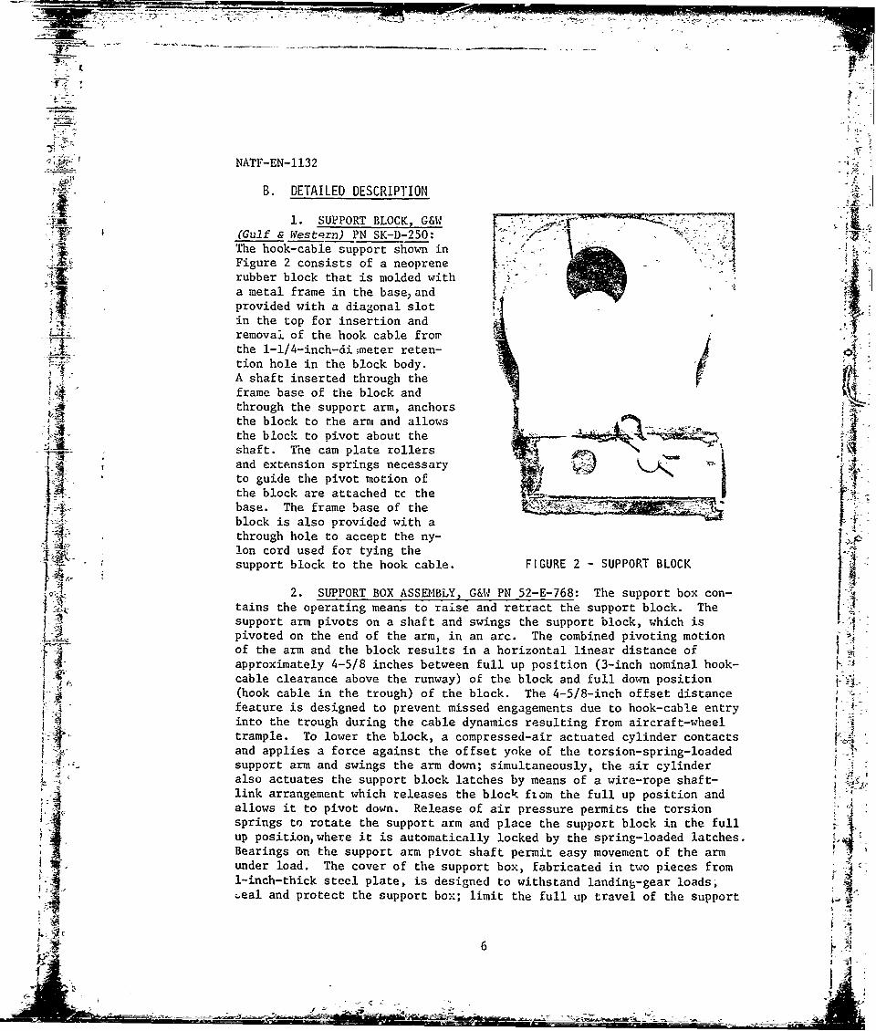
I (Gulf & Western) PN SK-D-250:The hook-cable support shown inFigure 2 consists of a neoprene '"2 4rubber block that is molded witha metal frame in the base andprovided with a diagonal slotin the top for insertion and
L/i~ removal of the hook cable from-E the 1-1/4-inch-di ;meter reten-
tion hole in the block body.A shaft inserted through the
4 frame base of the block andthrough the support arm, anchorsthe block to the arm and allows4 the block to pivot about the
. shaft. The cam plate rollersand extension springs necessary£3 'to guide the pivot motion ofthe block are attached tc the F!
-' base. The frame base of theKblock is also provided with a - - --- "-'
through hole to accept the ny-lon cord used for tying the
support block to the hook cable. FIGURE 2 - SUPPORT BLOCK 4
2. SUPPORT BOX ASSF-IBLY, G&W PN 52-E-768: The support box con-tains the operating means to raise and retract the support block. The
support arm pivots on a shaft and swings the support block, which ispivoted on the end of the arm, in an arc. The combined pivoting motionof the arm and the block results in a horizontal linear distance ofapproximately 4-5/8 inches between full up position (3-inch nominal hook- ;Jcable clearance above the runway) of the block and full down position(hook cable in the trough) of the block. The 4-5/8-inch offset distance
,"A feature is designed to prevent missed engagements due to hook-cable entryinto the trough during the cable dynamics resulting from aircraft-wheeltrample. To lower the block, a compressed-air actuated cylinder contactsand applies a force against the offset yoke of the torsion-spring-loaded
4,; support arm and swings the arm down; simultaneously, the air cylinderalso actuates the support block latches by means of a wire-rope shaft-link arrangement which releases the block from the full up position andallows it to pivot down. Release of air pressure permits the torsionsprings to rotate the support arm and place the support block in the full
up position, where it is automatically locked by the spring-loaded latches.Bearings on the support arm pivot shaft permit easy movement of the armunder load. The cover of the support box, fabricated in two pieces from
;eal and protect the support box; limit the full up travel of the support
j9_ 6

NATF-EN-1132
arm; and serve as a cam surface for the support block cam plate rollersused to guide the pivot motion of the support block. Up and down bumpersare provided to minimize shock from oscillations of the support arm whichresult when the raised hook cable is trampled by the aircraft wheel.
a. Also contained within the support box is an electricaljunction box, sealed aith watertight gaskets, which serves the up/downindicating switches and such electrical elements and th=rnostats requiredfor heater operatnon
b, A heated drain is prcvided in the bottom of the supportbox to avoid the accumulation of water. A screen prevents undesirableitems from entering the drainage system- The support-box drain openingis connected to the cross-runway drain which discharges into a heatedstorage tank that is periodically emptied.
M 3. HOOK-CABLE TROUGH, G&W PN 52-D-2616: The steel trough pro-vides a protective recess in the runway surface for retraction of thehook cable. It also provides a space for routing the air supply line
-4 , and heater elements beneath the trough cover on which the retracted hook
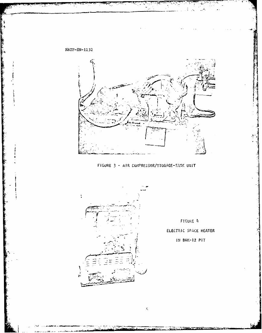
cable rests. The trough is located 900 to the runway centerline and isaligned with the tape payo-it side of the BAK-12 arresting-system decksheaves. Individual trough sections are installed between the supportboxes and in a 24-foot series arrangement to each runway edge called theend trough.V 4. PNEUM TC SYSTEM: Compressed air ior the pneumatic systemis supplied by means cf an electric-motor-driven compressor/storage-tankunit (shown in Figure 3 cn the following page) This unit is located inthe BAK-12 aircraft arrestment energy-absorber zir on the north side ofthe runway. The a.r temperature within the pit is maintained at approx-imately 65' F by means of eleccric space heaters of the rype shown inFigure 4 on the following page. To prevent the accumulation of excessive
moisture, the compressed-air stcrage tank of the unit is periodically
blown down and drained. The cut-in/cut-out type pressure regulator ofthe unit (and system) was adjusted to start and stop the compressor atair pressures of 110 and 125 ps; respectively. This type of system wasinstalled instead 'f the alternate high-pressure air 5torage bottle sys-tem specified in reference (f) be-ause it prc;ides a continuous air supplyfor the BAK-14 and eliminates the air-bcttle handling, charging, andsupply problem.
Ref: (f) Research and Development Center, Gulf & Western IndustrialProducts Company: P-3986, Manual for Operation, Maintenance &Installation of BAK-14 Hook Cable Support System; P-3987, Parts
& Drawing Lists
7
VN
. .. .. __ - iI I
NATF-EN- 1132
FIGURES 4.
V fyi
IN NA1 PI
N7 7 ., -
-5 +- .- , - <"'.=e - + + L+ ',I
S:- - - +-- - + '" -- I +
. .. .-+ " .'; + -- + > + < - ; .
-" + - ...42
IiI
-U,-..
_ -ELECTRIC SPACE HEATER
-+ I, +p iII 8AK-12 PIT
i - I :
% -i: II
NATF-EN-1132
a. The hook cable is lowered when the 3-way solenoid valve(shown in upper right corner of Figure 3, previous page) is energized,allowing compressed air to enter the 5/8-inch-diameter line to the aircylinders in the support boxes. The cylinders apply a force to the off-
{ .set yoke of the spring-loaded support arms and lower the hook cable intothe trough. The hook cable will remain down as long as the air cylindersare sufficiently pressurized. 7
b, The hook cable is raised when the 3-way solenoid valve isde-energized or the electric power fails. In either case, the 3-way sole-noid valve shuts off the air supply, and in conjunction with the quick-exhaust valve located in the near-side hand hole at the runway edge, ventsthe compressed air to the atmosphere. In the event of the loss of eithera-r pressure or electrical power, the torsion springs automatically raisethe support- and hook cable; thus the system is fail-safe in the up posi-tion.
. Manual operation of the system is possible by means ofthe manual override feature of the 3-way solenoid valve. In the event ofan electric power failure, this feature may be used to operate the system.
5. ELECTRICAL CONTROL SYSTEM: The BAK-14 controls operate on115-volt alternating current, single phase, 60 Hertz power supply. Themaster control is located in the Galena airfield tower and the portablecontrol at the BAK-12 aircraft arrestment energy-absorber pit on thenorth side of the runway. Either control may be used to operate thesystem. The control cables are shielded to prevent malfunctions causedby stray current and interference fields. All control-panel lights havethe push-to-test feature.
a. Only the tower master control is provided with a selectorswitch by which the tower or the portable control may be activated forcontrol of the system. The master control also has a red light to indi-cate the portable control is activated, a switch to raise and lower thehook cable, and lights to indicate the hook cable is up or down.
b. The portable control is installed on the end of ashielded extension cable which is grounded through the disconnect fittingin the BAK-12 pit, These features allow the BAK-14 operator to control(with tower permission) and observe the system operation at the runwayedge or to remove the portable control from the system with no effect ontower control. The portable control has a green light to indicate itsactivation by the tower, a switch to raise and lower the hook cable, andlights to indicate the hook cable is up or down.
c. The raise and retract functions of both controls aremonitored by mercury-type limit switches installed on each support arm to
4' indicate whether the arm is up or down. The switches are in series withthe system UP/DOWN position indicator light circuit, so failure in any oDL
99
7I
NATF-EN-1132
support box will prevent the hook-cable position light on the control
from lighting. Such failure can be either mechanical or electrical, or Aa switch malfunction. To avoid checking a multitude of possibilities on
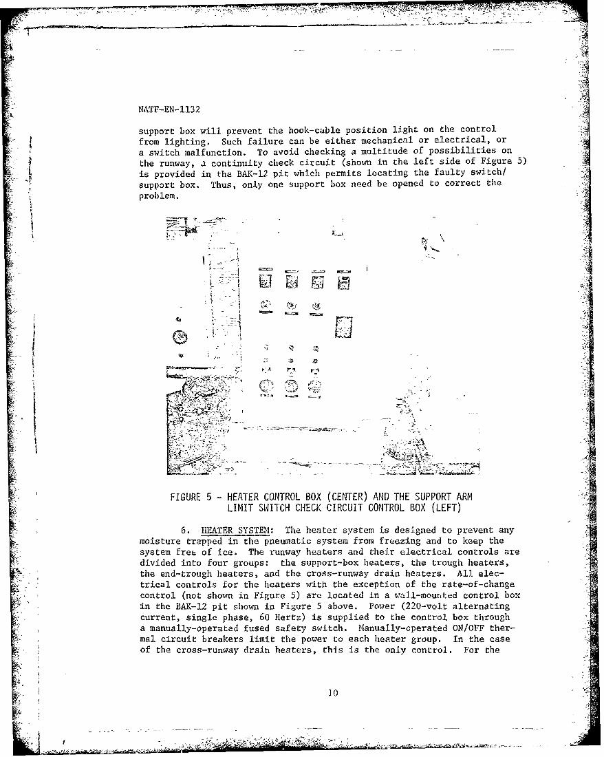
L the runway, a continuity check circuit (shown in the left side of Figure 5)
is provided in the BAK-12 pit which permits locating the faulty switch/
support box. Thus, only one support box need be opened to correct theproblem.
L LIMIT SWITCH CHECK CIRCUIT CONTROL BOX (LEFT)
" 6. HEATER SYSTEM: The heater system is designed to prevent any
moisture trapped in the pneumatic system from freezing and to keep the -
system free of ice. The runway heaters and their electrical controls are /'; . ,divided into four groups: the support-box heaters, the trough heaters,
',-. -the end-trough heaters, and the cross-runway drain heaters. All elec-
•trical controls for the heaters with the exception of the rate-of-change" control (not shown in Figure 5) are located in a wall-mounted control box '' "in the BAK-12 pit shown in Figure 5 above. Power (220-volt alternating
:i current, single phase, 60 Hertz) is supplied to the control box through .~a manually-operated fused safety switch. Manually-cperated ON/OFF ther- -i
~~mal circuit breakers limit the power to each heater group. In the case --tof the cross-runway drain heaters, this is the only control. For the•0
f

NATF-EN-1132
three remaining heater groups, power is adjusted by means of manual rheo-
stats and regulated by thermostats: a rheostat for each group is located
on the panel, and a thermostat for each group is located in the support
box, the trough, and the end trough nearest the BAK-12 pit. In addition,
each heater group is provided with a rate-of-change control (located above
the heater control box) to adapt the heating rate to the seasonal chlanges
in temperature.
a. The heater elements are the mineral-insulated, metallic-
sheathed t',pe with potted leads attached to a cold section. The box and
trough he-ters have a stainless-steel sheath, the drain heaters a copper
sheath. All heater units are capable of wet/dry service, and are acces-
sible for replacement.
b. The heater element in the support box surrounds the air
cylinder ann is in direct contact with the air supply line. The hairpin-
shaped trough heater is located on either side of the air supply line in
the space below the cover assembly of the trough. One heater is located
in each trough section between the support boxes, and two heaters are lo-
cated in each end trough. The cross-runway drain heaters extend from
hand-hole to hand-hole and protect the entire length of the drain.
c. To facilitate detection of heater malfunctions, a contin-
uity check circuit is provided on the heater control box in the IIAK-12J pit by which the faulty unit may be identified. The continuity of the
drain heaters must be checked at the junction box located in the hand
hole on the control-pit sidt of the runway.
7. BAK-12 A[RCRAFT ARRESTING SYSTEM: A photograph of the BAK-12/
BAK-14 installation and the F-4E aircraft is shown in Figure 6 below.
f
4C,,
FIGURE 6 - BAK-12/BAK-14 INSTALLATION AND THE F-4E AIRCRAFT
'I'
- - - - - - - - - -
4 NATF-EN-1I32
For this test program, the BAK-14 retractable hook-cable support system
was used in conjunction with the BAK-12 system which was configured as
follows:
a. Type installation - concrete pit, permanent installation
with runway-edge sheaves.
b. Location - 2,360 feet from the approach end of runway
heading 250.
c. Arresting-sheave span - as required for a 150-foot-wide
runway.e.d
d Hook cable - PN 512875-153, 153-foot--long by 1-1/4-inch-! ~diameter nonrotating wire rope.
-!-
8. F-4E AIRCRAFT: Pertinent data is as follows:
a. Configuration - empty fuel tanks installed on the wing
pylons.
b. Basic weight - 32,700 pounds.
c. Test weight range - 39,400 to 42,500 pounds.
d. Main-wheel span - 17 feet 11 inrhes.
IlII TEST PROCEDURE
A. FUNCTIONAL INSPECTIONvA.1. A functional inspection was initially conducted
to determine
the condition of the BAK-14 retractable book-cable support system and toI; verify its readiness for testing. To expedite the functional inspection,
the hook cable of the BAK-12 aircraft arresting system was not installed
in the BAK-14 support blocks,
2. Using reference (g) (included as Appendix A of this report)
as a working checklist, the BAK-14 heater, pneumatic, and control sys- f,
tems were functionally checked to determine if each control input pro-
duced the required response in the system.
i Ref: (g) NAVAIRENGCEN Test Directive No. MISC-337 of 8 Nov 1973: BAK-14
Cold Weather Tests at Galena AFB, Alaska I
12
_ ,~. ~ - - -.--4
--
NATF-EN-II32
B. DYNAMIC TESTS
'1 1. TRAMPLES ANDARRESTMENTS: After the functional inspection wassatisfactorily completed, the hook cable of the BAK-12 aircraft arrestingsystem was installed in the BAK-14 support blocks in preparation for F-4Eaircraft tramples and arrestments. The procedures for the dynamic testswere as follows:
a. The hook-cable supports were inspected after each test -4To , evauheas hlo okcbertntosaaiit tespprsa o
event. No attempt was made to cycle the system between events.
b. The hook cable was tied to each support block with adoubled length of 550-pound nylon cord for the initial six tramples,
°' - To evaluate the hook-cable retention capability of the supports at low
A, ambient temperatures, the nylon restraints were not installed for the 4remainder of the tests.
c. The tramples and arrestments were conducted on runway 4heading 250.'.
iii" ' d. The tramples were completed by the touch-and-go methodof cycling the aircraft,
It e. The taxi-in method of approach to the system was used to
1- complete the arrestments.
-- f. All arrestments into and high-speed tramples of che BAK-14/BAK-12 were test program event, Another BAK-12 system on the runway wasused for operational arrestment6.
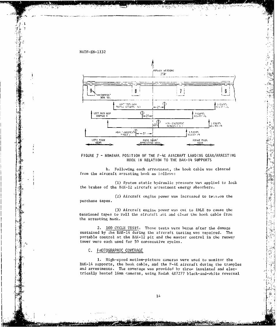
i, .g,, The thice-icot-,hile runway centerline stripe was used asan OFF-CENTER distance gu:de during :he approache; to the gear; a piece
of high-visibility red clcth tied to the hook cable at the desired OFF-CENTER distance was used as the target fcT the aircraft nosewheel. The-.desired OFF-CENTER dstanes (and nominal OFF-CENTER distances of the_:_' aircraft), irt relat~ion to the a ic-caft landing gear and the BAK-I14 support
boxes, are shown in Figure 7 on the following page a
t IV,1~
.5:
13 r5
.-5 " -
. . ..-... ... . .. . . .. . ..- -
NATF-EN--1132
AJ
;RUN AY HEADING250-
SUPPOR,BOX NO.
-' ,1
1% WI. EfEVE'.%,
LEFT MAIN GEAP 9 EVNTRAO'PLE 9 10-5 I
~, 6iW~1. & ~EVETS
LETMI FOLW iSAEtVi 3 I 3 EVETS
LF MANNOSE fdAR/ R]GtiT M-A I NGEAR .. ~PREST ING ii"K~ GEt.R
FIGURE 7 -NOMINAL. POSITION OF THE F-4E AIRCRAFT LANDING GEAR/ARRESTINGHOOK IN RELATION TO THE BAK-14 SUPPORTS
1'h. Following each arrestnheat, he hook cable was clearedI -4V~- from the aircraft arresting hook as follows:
f(1) System static hydraulic pressure wa ; applied to lock }7_ r the brakes of the BAK-12 aircraft arrestment ener-gy absorbers. -
(2) Aircraft engine power was increased to te~is~on theI{ purchase tapes.
(3) Aircraft engine power was cut to IDLE to cause thetensioned tapes to roll the aircraft att and clear the hook cable fromthe arresting hook.
2. 100 CYCLE TESTS; These tests were begun after the damagesustained by che BAK-14 during the aircraft testing was repaired. The
~~-4 portable control at the BAK-12 pit and the master control in the runwaytower were each used for 50 consecutive cycles.
C. PHOTOGRAPHIC COVERAGE
1. High-speed motion-picture cameras were used to monitor the
BAK-14 supports, the hook cable, and the F-4E aircraft during the tramples
I. trically heated 16mm cameras, using Kodak 4X7277 black-and-white reversal
fWi
ag .j
4 NATF-EN-1132
film at 200 frames per second. The cameras were located on the southside of the runway and in relation to the hook-cable battery positionas follows:
'0.
a. A fixed camera located midway between the BAK-12 aircraftarrestment energy absorber pit and the runway-edge sheave directly in linewith the hook-cable battery position.
b. A fixed camera and a hand-held pan camera on the edge ofthe runway located approximately 150 feet upstream of the hook-cable bat-tery position.
2. A winterized 35mm camera was used to take still photographsof the installation, equipment failures, and problem areas.
D. INSTRUMENTATION: The test parameters were visually observed bythe Navy test team and measured by direct indicator instruments locatedin the Galena runway control tower, the F-4E aircraft, and at the BAK-14test site. The parameters and the methods of ,ieasurement are tabulatedas follows:
Parameter Recording Methu- Location
TemperatureAmbient Thermometer Galena TowerSurface Surface-temperature thermometer BAK-14 Siteyr :. Local ambient Thermometer , ,
WindVelocity Anemometer Galena TowerDirection Wind indicator
AircraftIndicated airspeed Pitot tube instritment F-4 AircraftOFF-CTR position Direct observation BAK-14 SiteGross weight Basic weight & fuel quet t, F-4 Aircraft
indicator
Time Stopwatch BAK-14 Site
E. TEST LIMITS: The pilot of the F-4E aircraft determined theflight operating conditions, minimum landing criteria (OPNAVINST 3710.7G .(NATOPS General Flight and Operating Instructions Manual)), and safe run-way conditions. I. was at the discretion of the pilot to brake, arrest,
.- ; or take off in case of a missee engagement or equipment failure.
S--
15

NATF-EN-1132
IV TEST RESULTS AND DISCUSSION
-~A. FUNCTIONAL INSPECTION
1. HEATER SYSTEM
a. Surface temperature b-,, tere taken on the center of
the large cover of each support box an,; he wnll of the hook-cable
trough (see Figure 8) at one and two ie<- o the :ight (north) of each4
jJ,
A!" tiiaino T spotbxsi herna.Tecndtosdrn h
supr .Tesurface temperature ofve thwrogecvrre:mly ol
Ambient air temperature -2' F Chill factor -3*FSupport-box 'heater unlit -ower setting =287
Trough heater unit power setting 267IrThe results of the survey are presented on the following page.tIL
- ---

NATF-EN-1132
Temperature ( F) Temperature F)
Support Box Trough Wall Support Box Trough WalliR Box No. Cover 1 it 2 Ft Dox No. Cover 1 Ft 2 Ft
1 -10 5 28 8 -11 17 192 -12 17 30 9 - 8 16 19
-10 -12 10 -10 12 1920 24 11 -11 14 19
5 -11 20 35 12 -10 9 186 -9 18 26 13 -10 9 18
J 7 -1.0 22 18 14 -12 10 22
(1) When operating at power settings of 28% (above data)or 50% (not recorded), the heaters in the bottom of the support boxeshad little or no effect on the surface temperatures of the support-boxcovers. The maximum heater power setting (100%) produced a surface4'temperature of only 70 F at a location above che heater element adjacent
(2) At a trough heater power setting of 26%, all exeeptone wall temperature were below freezing. These temperatures were lowerthan expected because thc trough remained ice free even though the ambientair temperature was -2" T. It is believed that the temperature of theexposed trough cover assembly remained well above 320 F.
b. The end-trough wal surface temperature was sampled at7-foot intervals from the outboard support boxes (support boxes 1 and 1z"-to the end of the troigh at the edges of the runway. The results of the J
survey were as follows:
j~-4 TroughA Heater
Power 1;:3;perature (0 F) End-Trough Wall Temperature (0 F)jetting ibLent Chill Support Box 1 Support Box 14
(%) ir Factor 7 Ft 14 Ft 21 Ft 7 Ft 14 Ft 21 Ft
S 50 -16 -45 17 23 22 16 18 20
26 -2 -8 46 10 42 40 38 401
The end-trough wall temperatures show a significant difference betweenthe 50% and the 26% h'ater power settings. The data shows the lowerpower setting resulted in the higher temperature. It is believed that
this anomaly was due to a different rate-of-change control setting which_ ~ was inadvert ntly used with each heater power setting. However, both
-tts of temperature data give positive confirmation of heater operation. 2
A - 1 r1
A AtM~ W
7
A, NATF-EN-1132
c. The teinperarurs at th~e bottcm of each sup port box 1 asampled as follows:
Ambient air cemp-rai'ie -16 r~, ClM11 Eao&.r -45 FSupport box heateT powe: st-Ltirng 100%
_____________ SUPPOPI, BOX No1
1 2 3 45 6 8 8910111213 14
Terperacure (F) 84 88 97 70 68 56 ?G 5&t 50 8/ 44f 45 4~6 84
The iL-foct-long ther-mornEtars ~sepiaced nerl Ert-.:a_ in ezch support-bax covet opening on the tfoigb s-de , 4 tne raised suppcrzt bl-Ck- Thevariation I.t, the fcl'erature~ s 6-;e r the d ,fleiEnes in the prcximityof the rhermcrteter bL ;b to the l~e.rerirt -n th-E bct'e,:M oi the box.The temperatute data c' nfirms -bt -peratkr ci :he beacrers in all of theSupport bCXES.
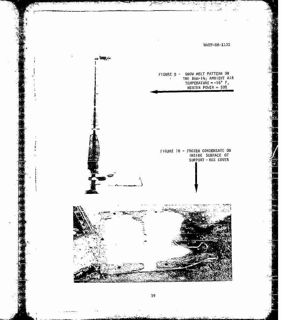
d- fig-_re 9 (see nsyt PSagE) s~c,,, the resl-Iits of a freshsnowfall on rhe BA-K-14 Thbe sncT remain._d cr. t e-nrport 'box covers butmelted &7.dicz EblkrnatE d~etx :ni-c th~e _,Drh. and az 7ud theF
p e r -t L',e " -i 6- F srd 0che 'as cc-~tn
tweea' Qpp-v'- *!cxes 2 Ld 3 7h- i-Kater _-.rdit._ar~dby the _ aia-e-rt':spportbox 3 (p _igr ph bc-a Zl- c~-g17 r~l Ctic -1in FIgUIE 9 (- Cr~ gE) T,, y dt -3%,a dar, heactejs
* ~~was notcr4:c
f Th' bcicw-rvn :f~-~c rite spport-box covers(paragrap- a rb~ di e-.-- nn~t ~ cr z+,& utd d z' th e
oc'~v2thin -the -,Lrpcr- : ' ~ cc ~r ~twhen the ;,upr ,rt-b;y: -.- - :eI S-- 1gire WI cr rhla n-;ext page.
box, tt tuch, an~d S'--rtghL~ I:af an ac,_Trp t:Aq-c~tc~le hricut r.Nda o~ hoar-t C-a trc7 par--i 7,P tine BAK-12 r-. The
b - eater nclbcx iS -hori in Fjgtre 5 cr. Cage __O The verifiratron wasUnsatI'll UCIcv, faaz OP fol±-n -szn-.
zii, th -vto tt ie y2_ I'n tu.c' -j di:* iiand/or --b red tcesr p5 itlcv indawoar-r f-Lgii spo-rcd Icb .:~tvwired (pcssiihl!y irrc-.-ranged) on'alTr~i~z ~t~z
(2) The relays actijated by tbe surrt box end the troi)ghheater operatE itest swirches wer, Cxpioa 4, n-s he l d in the
18
'it- NATF-EN-1132
I FIGURE 9- SNOW MELT PATTERN ONTHE BAK-14; AMBIENT AIRTEMPERATURE =-160 F,
HEATER POWER =50'
FIGURE 10 -FROZEN CONDENSATE ONI
INSIDE SURFACE OF'
SUPPORT -BOX COVER
1<11
NATF-EN-1132
test position. Although operating personnel attested that the end-troughrelay was also occasionally noisy, the relay operated normally during thefunctional inspection.
(3) The inoperative trough heater between support boxesI " 2 and 3 was not detected.
were h. The control-system and the heater-power-supply voltages
were verified to be 112 and 220 volts respectively.
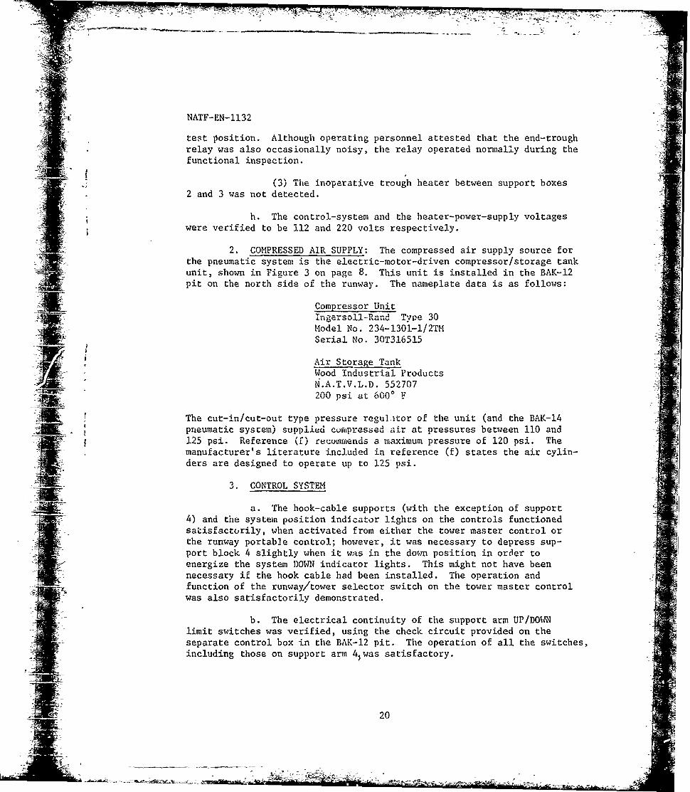
2. COMPRESSED AIR SUPPLY: The compressed air supply source forthe pneumatic system is the elEctric-motor-driven compressor/storage tankunit, shown in Figure 3 on page 8. This unit is installed in the BAK-12pit on the north side of the runway. The nameplate data is as follows:
Compressor Unit2 Inge rso 'Rand Type 30
Model No. 234-1301-1/2TMSerial No. 30T316515
Air Storage TankWood Industrial ProductsN.A.T.V.L.D. 552707200 psi at 6000 ,
The cut-in/cut-out type pressure regul-tor of the unit (and the BAK-14pneumatic system) supplied curfpressed air at pressures between 110 and125 psi. Reference (0 recuiriends a maximum pressure of 120 psi. Themanufacturer's literature included in reference (f) states the air cylin-ders are designed to operate up to 125 psi.I i 3. CONTROL SYSTEM
a. The hook-cable supports (with the exception of support4) and the system position indicator lights on the controls functionedsatisfactorily, when activated from either the tower master control orthe runway portable control; however, it was necessary to depress sup-port block 4 slightly when it was in the do-n position in order toenergize the system DOWN indicator lights. This might not have beennecessary if the hook cable had been installed. The operation andfunction of the runway/tower selector switch on the tower master controlwas also satisfactorily demonstrated.
b. The electrical continuity of the support arm UP/DOWNlimit switches was verified, using the check circuit provided on theseparate control box in the BAK-12 pit. The operation of all the switches,including those on support arm 4,was satisfactory.
Mi 20

NATF-EN-l132
t c. The time required to raise and to lower the supports (with-out the hook cable installed) was 13 and 7 seconds respectively.
. B. DYNAMIC TESTS :11. AIRCRAFT TRAIPLES AND ARRESTMENTS: These tests consisted of A
12 tramples and 6 arrestments of the F-4lE aircraft. The purpose of thesetests was to determine the effects of landing-gear trample, landing-gearimpact, hook engagement, and aircraft-hook impact on the BAK-14 hook-cablesupports. The following is a tabulation of the events conducted:
_jSjed (Kn)lndi-
F-.E Aircra-t cated Arzb- Event Weight Air- Wind Tep
Ao_. T (Lb)Approach Planned sVed (En/Dir) F Petarks _._
1 Note 1 42,500 L 60 60 61310 -24 No damage2 " 80 803 " NR Tot %/Go 100 150
4 Vote 2 41,500 . 613405 " 41,100 0 1U 4/340 -23 '-7 8 6 restraints failed--not replaced6 1,000 '/330 Wet main landionv gear hit support 9
7 41,900 Taxi 140 b/340 -lb All r,trafnti rvov~d. nosewAhec hit support 88 41,700 Touch/Co 4 309 41,200 ". 360 "
10 44,500 Taxi 100 8/36011 42,700 Touch/Go " 145 S1350 ,12 42,400 "
J13 Note 3 39,400 laxi W60. 3 2;*4 o7 jp- truaz; a. A dewntrearn sl1ots crack-I14 " 38,700 ) "0 a3 4! ilr .b & 9 lat.-h 'pring, filled; '9 latch shaft bent
4 jfli'Ir' d,taeh d15 41,700 100 9O 1-1 -is - & 4 sots chippeq; A*8 & 14 bases cracked
16 Note 4 40.700 ;/330 " !3 l chipped; -1-6, B, S 10-14 bases ,rcke17 " 39.700 " 105 '/340 " 3, 5. t, 6, & q bases severeli cracked18 100 4350 iHook it support 8; e5, 6, & 8 detaed (5 & 6 re-
nain.d on Cabl); :%S slot chipped, latch pivotshaft & anchors detached. pusherblork rotated outof a1!gn=nt
NOTES: The fo1o1ving were artrepted:1. Trample the hook cable with the left -in linding ge.r ni£r-: between supports 8 and 9.2. Trarple; impact qupport q with left main 1Uniin, geir.3. Arrestment: Engsge hook cale -eid,,ax b --. en upport; 7 and 8.4. Arrestment-: Impact support 8 with the he.4
a. Aircratt Landing-Gear Tramples
(1) The BAK-14 hook-cable support system sustained no apparentdamage other than the failure of the nylon cord restraints on supports 7 and 8. -I
The failure of the No. 7 restraint was caused by faulty installation; failureof the No. 8 restraint may have been caused by abrasion of the nylon cord Jagainst the support-box cover.
(2) Two probable impacts of the support occurred during thenine attempts as indicated by tire marks on the runway and on the support:support 9 impacted by left main landing gear of the aircraft at 120 knots
21I

NATF-EN-1132
indicated airspeed (event 6), and support 8 impacted by nosewheel of the
aircraft at 140 knots indicated airspeed (event 7). The BAK-14 hook-cablesupports sustained no apparent damage during either of these events. IObservation of high-speed motion-picture film of both events revealed thatthe aircraft tire depressed the support and the support arm into the sup-port box with minimum distortion of the support and the aircraft tire.
b. Aircraft Arrestments
(1) All attempts to engage the BAK-14 supported hock cablewere successful; no bolters occurred.
(2) The BAK-14 supports were damaged to some extent duringeach arrestment because of the detrimental effects of the low temperatureson the supports. Under normal temperatures (above freezing), the rubbersupports are pliable. During these tests, however, the extremely lowtemperatures hardened the supports to such an extent that they fracturedduring hook-cable pullout. The failures occurred in two areas on thesupports: the cable-entry slot and within the metal frame base.
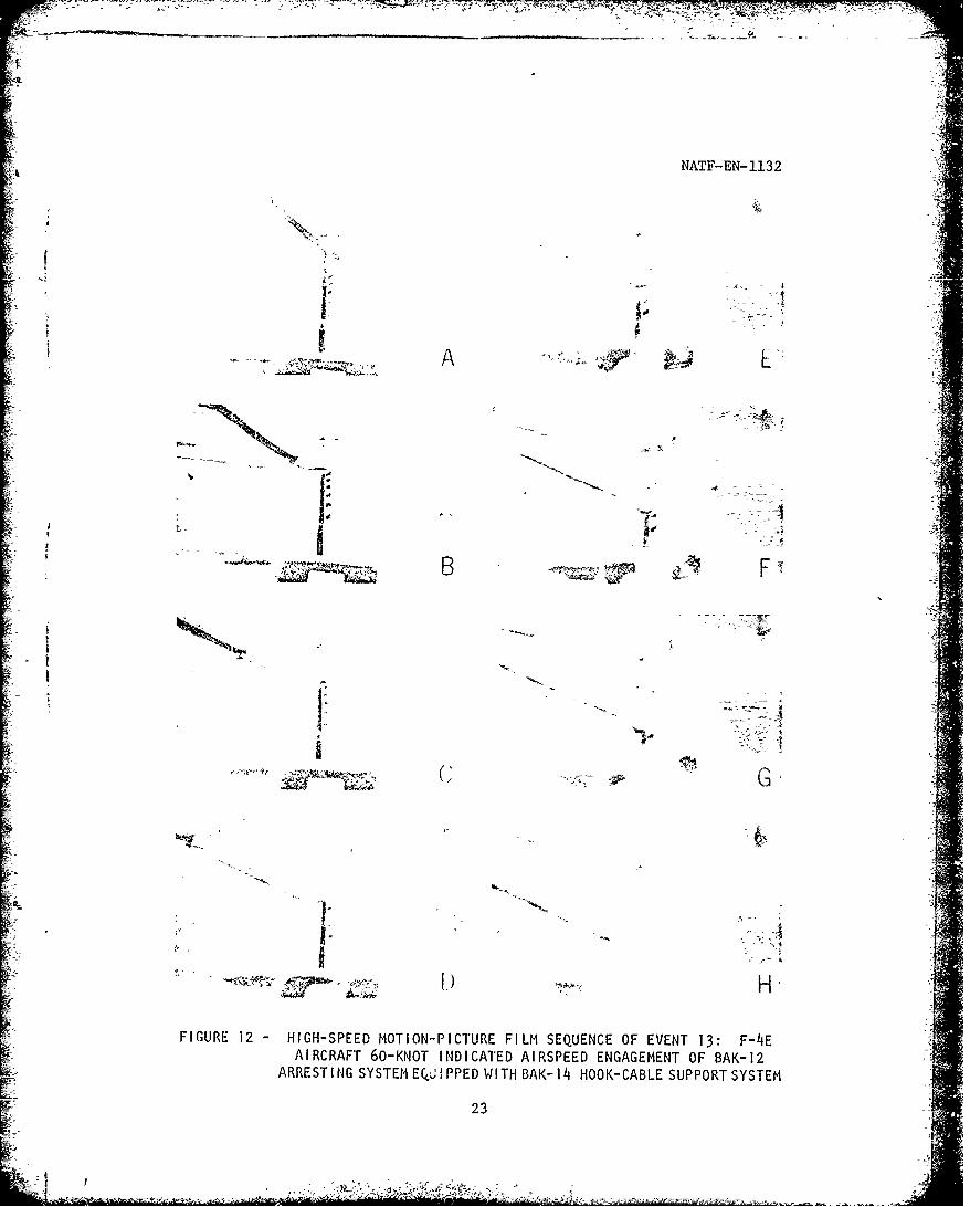
(a) The less serious was the hook-cable entry slotarea. Figure 11 shows a damaged support: chunks of rubber were rippedout, enlarging the cable entry slot. Supports 7 and 9 were damaged inthis manner during the initial engagement (event 13) at 60 knots indi-cated airspeed. A high-speed motion-picture film sequence of this eventis shown in Figure 12 on the following page.
FIGURE 11 - FAILURE OF SUPPORT AT THE HOOK-CABLE ENTRY-SLOT AREA
22
- , t y, A - c rm X ' - -- i-t, - ' .. ... .
NATF-EN-1132
1 '43
"4A
i!-4-
B _ F' : ---
F I U R 1 2 H I H S P E M T O -I R F I M S Q E C O F V T1: F= -
---
ARA ,K ID T A
! -S
Hi
i'FIGURE 12 - HIGH-SPEED MOTION-PICTURE FILM SEQUENCE OF EVENT 13: F-4Et
AIRCRAFT 60-KNOT INDICATED AIRSPEED ENGAGEMENT OF BAK-12,'
[- ARREST I NG SYSTEM EQUI PPED WITH BAK- 14 HOOK-CABLE SUPPORT SYSTEM
E' 23
-'55 ,
S ;7
4 --
71P2
NATF-EN-1132
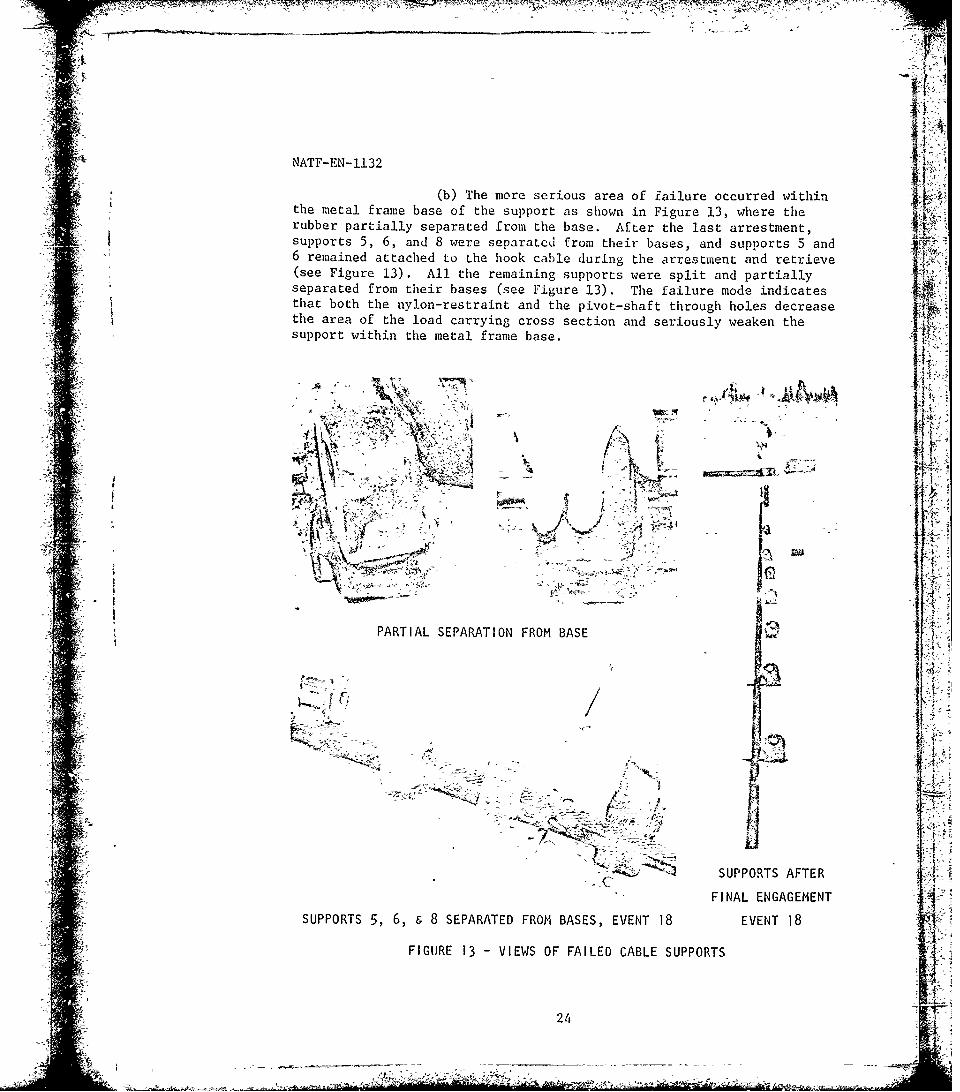
(b) The more serious area of failure occurred withinthe metal frame base of the support as shown in Figure 13, where therubber partially separated from the base. After the last arrestment,supports 5, 6, and 8 were separated from their bases, and supports 5 and6 remained attached to the hook cable during the arrestment and retrieve(see Figure 13). All the remaining supports were split and partiallyseparated from their bases (see Figure 13). The failure mode indicatesthat both the nylon-restraint and the pivot-shaft through holes decreasethe area of the load carrying cross section and seriously weaken thesupport within the metal frame base.
W "I
'Off OWN "A
PARTIL SEPRATIN FRO BAS
A, ~ -.' z4
- SUPPORTS AFTER
.... FINAL ENGAGEMENT -SUPPORTS .6, & 8 SEPARATED FROM BASES, EVENT 18 EVENT 18
: .FIGURE 13 -VIEWS OF FAILED CABLE SUPPORTS
,J4-i ~
NATF-EN-1132
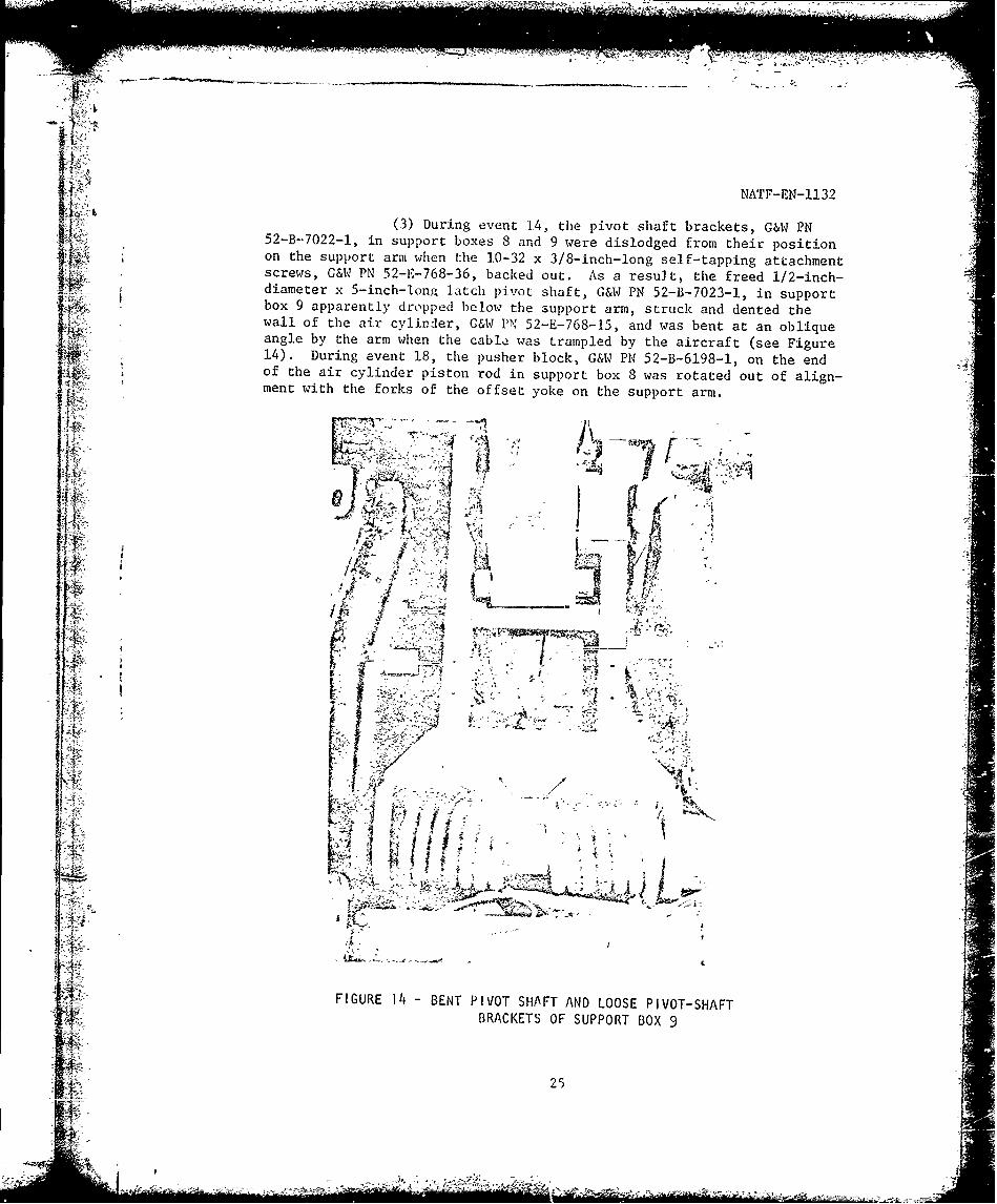
Ii' (3) During event 14, the pivot shaft brackets, G&W PN52-B-7022-l, in support boxes 8 and 9 were dislodged from their positionon the support arm when the 10-32 x 3/8-inch-long self-tapping attachmentscrews, G&W PN 52-1-768-36, backed out. As a result, the freed 1/2-inch-diameter x S-inch-long latch pivot shaft, G&W PN 52-B-7023-1, in supportbox 9 apparently dropped below the support arm, struck and dented theIi wall of the air cylinder, G&W PN 52-E-768-15, and was bent at an obliqueangle by the arm when the cable was trampled by the aircraft (see Figure14). During event 18, the pusher block, G&W PN 52-B-6198-1, on the end 4
Mt of the air cylinder piston rod in support box 8 was rotated out of align-ment with the forks of the offset yoke on the support arm.
- ti
ii It5 - .a, -w:
:!--FIGURE 14 -BENT PIVOT SHAF T AND LOOSE PIVOT-SHAFT, i: .BRACKETS
OF SUPPORT BOX 9
al 25
I /f
-'' 7- - _
NATF-EN-1132
(4) The latch extension springs, G&W PN 52-C-3247-3, insupport boxes 8 and 9 were also dislodged from their attachment pinsduring event 14. During reinstallation, it is necessary to excessivelydistort the loop end of the springs because of the poor accessibility ofthe attachment pins.
(5) Nosewheel tire marks on the runway following the lastarrestment (event 18) indicated a probable aircraft-arresting-hook impactof support 8 at an indicated airspeed of 100 knots. The validity of theevent for hook-impact evaluation is questionable because the support waspartially separated from its base as a result of the previous events. Inview of the damage incurred during normal arrestments, it would appearthat the support would be severely damaged by a direct hook impact.
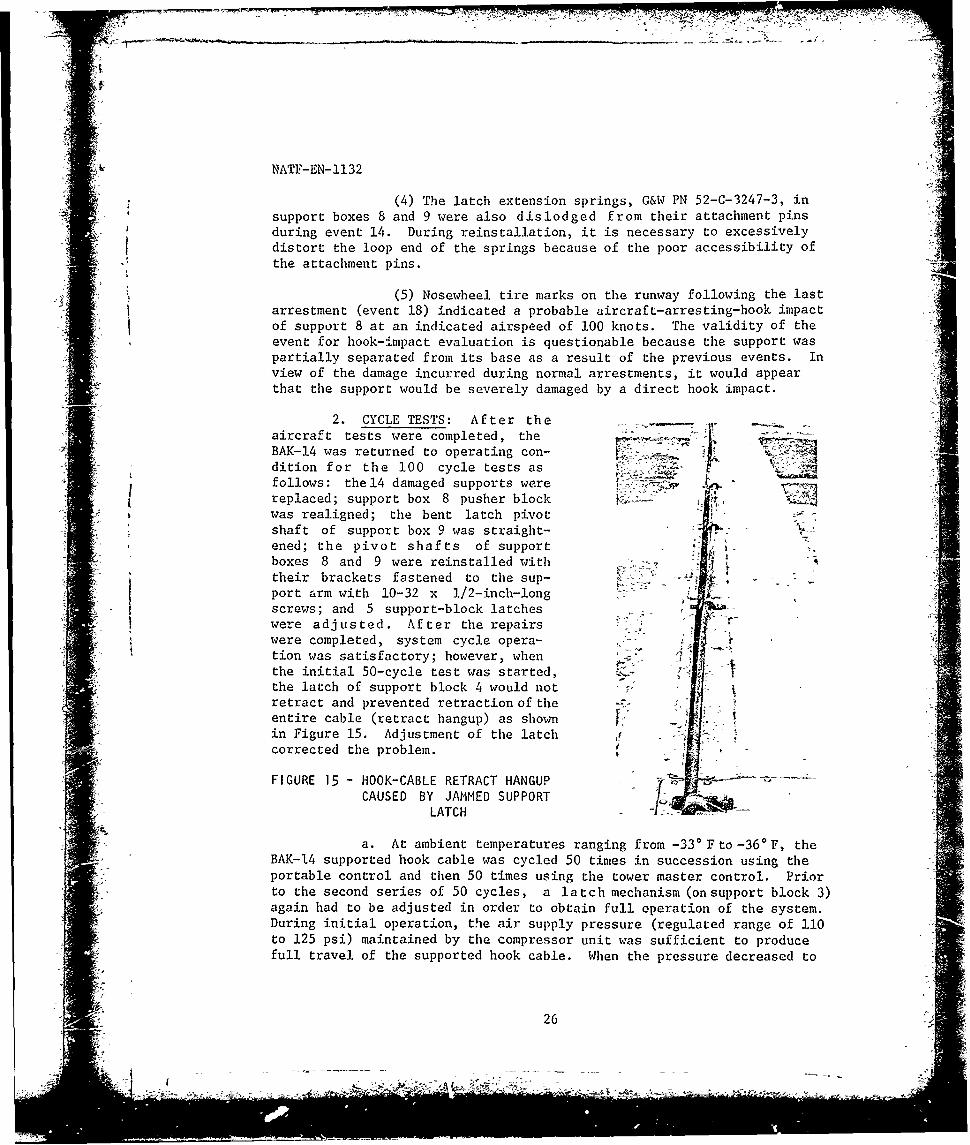
2. CYCLE TESTS: After theaircraft tests were completed, the -
BAK-14 was returned to operating con-dition for the 100 cycle tests asfollows: the14 damaged supports were .
replaced; support box 8 pusher blockwas realigned; the bent latch pivotshaft of support box 9 was straight-ened; the pivot shafts of support . ,boxes 8 and 9 were reinstalled with -
their brackets fastened to the sup-port arm with 10-32 x 1/2-inch-longscrews; and 5 support-block latcheswere adjusted. After the repairswere completed, system cycle opera-tion was satisfactory; however, when ,the initial 50-cycle test was started, 4the latch of support block 4 would notretract and prevented retraction of theentire cable (retract hangup) as shownin Figure 15. Adjustment of the latchcorrected the problem.
FIGURE 15 - HOOK-CABLE RETRACT HANGUP - --
CAUSED BY JAMMED SUPPORTLATCH -"--
a. At ambient temperatures ranging from -330 F to -36o F, theBAK-14 supported hook cable was cycled 50 times in succession using theportable control and then 50 times using the tower master control. Priorto the second series of 50 cycles, a latch mechanism (onsupport block 3)again had to be adjusted in order to obtain full operation of the system.During initial operation, the air supply pressure (regulated range of 110to 125 psi) maintained by the compressor unit was sufficient to producefull travel of the supported hook cable. When the pressure decreased to
26

NATF-EN-1132
approximately 70 psi due to the high air consumption of the continuouscycling, the hook cable would not fully retract. The compressor was thenallowed to recharge the storage tank. The Q-cling was resumed in sets
4 , of 10 cycles, with a pause between each set to allow the compressor torecharge the air storage tank.
b. The average Lime required to raise and lower the hookcable with either control was approximately 13 and 7 seconds respectively.This compares to the 15- and 8-second raise and lower cycle times of thereference (e) system prior to the installation of a quick-exhaust valve,Schrader PN 30077-9500, in the air supply line at the three-way solenoidvalve and in the hand hole at the runway edge. With these valves in-stalled, the time required to raise ti'e reference (e) system was decreasedto 5 seconds, which resulted in 13 seconds for the combined raise/lowercycle. The Air Force requirement is a maximum time of 15 seconds. Thepreload of the support-arm torsion springs may also affect system cycletime. The torsion springs of the subject system are preloaded with1.484-inch-diameter spring blocks, G&W PN 52-B-6170-2. The reference(e) torsion springs provide a greater preload because of the 2.25-inch-diameter spring blocks in each outboard box and the 1.625-inch-diameterspring blocks in the remaining boxes.
c. The hook cable DOWN indicator light on both the portableand the tower controls did not function during the cycle tests. Thecause of the malfunction is not known. It could be the result of damagecaused L7 the aircraft tests or the incorrect reinstallation of themercury switches following support-box repairs, since adequate instruc-Lions concerning installation of the switches were not available.
d. ThE hook-cable trough remained ice free during the entiretest cycle at temrporatures ranging from -33' F to -36' F.
C. TEST EQUIPMIUT
1. HOOK-CABLE INSIALLATION
a. At an ambient temperature of -2-0 F, it took five "hen,two using a 1-inch-diameter o.pt and a pry bar, 1/2 hour to install thehook cable in the retention hole ,:f the BAK-14 supp.orts. The neoprenerubber supports were extremely ha:d and stiff. Maximum manual effortwas required to open up and align the diagonal entry slot in the supporttop so the hook cable could be forced in.
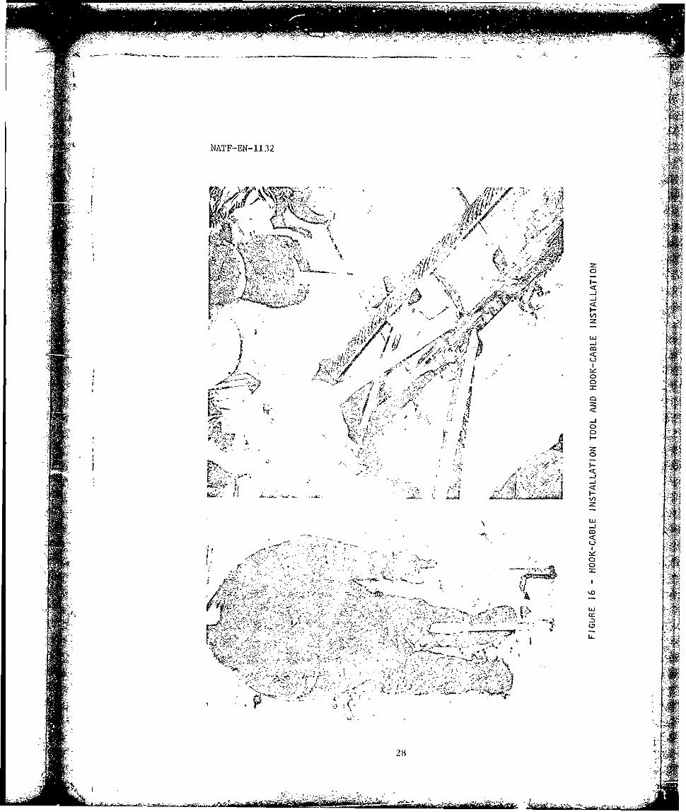
b. To facilitate installation of the hook cable in the sup-ports, the installation tool shown in Frgure 16 on the following page wasfabricated. Hook-cable installation time -.aas reduced to less than 10minutes using 4 or 5 men: 2 men used thi tool to open the entry slot,2 men used pry bars (I to align the opened slot with the hook cable andone to prevent movement of the su port arm), and 1 man to insert the cable.
121
---. ~ - -- -~---- - ---.- A---~'r-~~-t'u.- - W~ 4r~- ~
C- -fl.,~
-A -- -
A -
NAT F-EN- 1132
N-5 ~ - -
'$5- -'%vtr'i4~ \ 4; -sbA'v~\ -- A
"it C' £13- - t&-;s;;
2-i'- -~ ~ 0- (C V /1)
4 /
4 ,""' t~~$t~ f<2' ~t. - Aj- - --- Vtr" C-)'4 Lx
A, 0F ~ ~ ~%''-a ~5Y 4 it
-JVI-- ti 0 ttZa 4- - i 0- - " -
/ - I-*
0
- - zILIS2J__ Uz
-J 1~cc
-~ C-) i-s7' tp-- 0
5 C ~N&At ~ - -C-.. -~I I I-f.4 A - '0
- IttVI% -~'< ~-W ~ C? 7K> 4,~.rK t t Lid JrVt -
5 --i- -
*5
-~ -'N - - /
1. t - LI- - t~---4t~/- 'a" - -~ 44
NATF-EN-1132
It is believed that the addition of a crosspiece on each hand1le of theinstallation tool woo'1d allow it to be used to both open and twist theentry slot of the support to align it with the hook cable, therebyeliminating the need for one of the pry bars.
2. HOOK-CABLE RESTRAUINT INSTALLAr ION
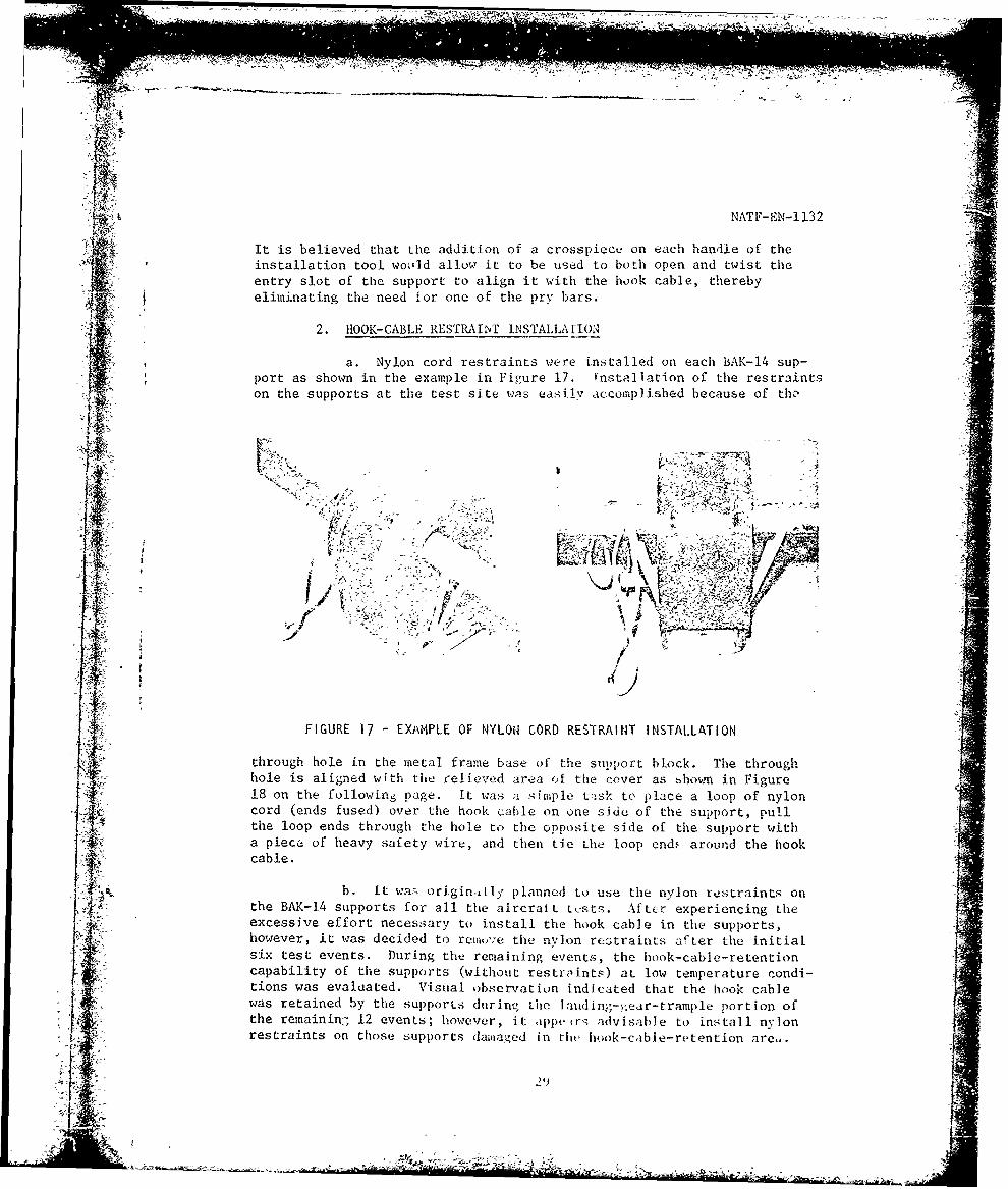
a. Nylon cord restraints were installed on each BAK-14 sup-port as shown in the example in Figure 17. tnstallation of the restraintson the supports at the test site was easily accomiplished because of th,'
VZ 4_1 4
FIGURE 17 -EXAMPLE OF NYLONl CORD RESTRAINT INSTALLATION
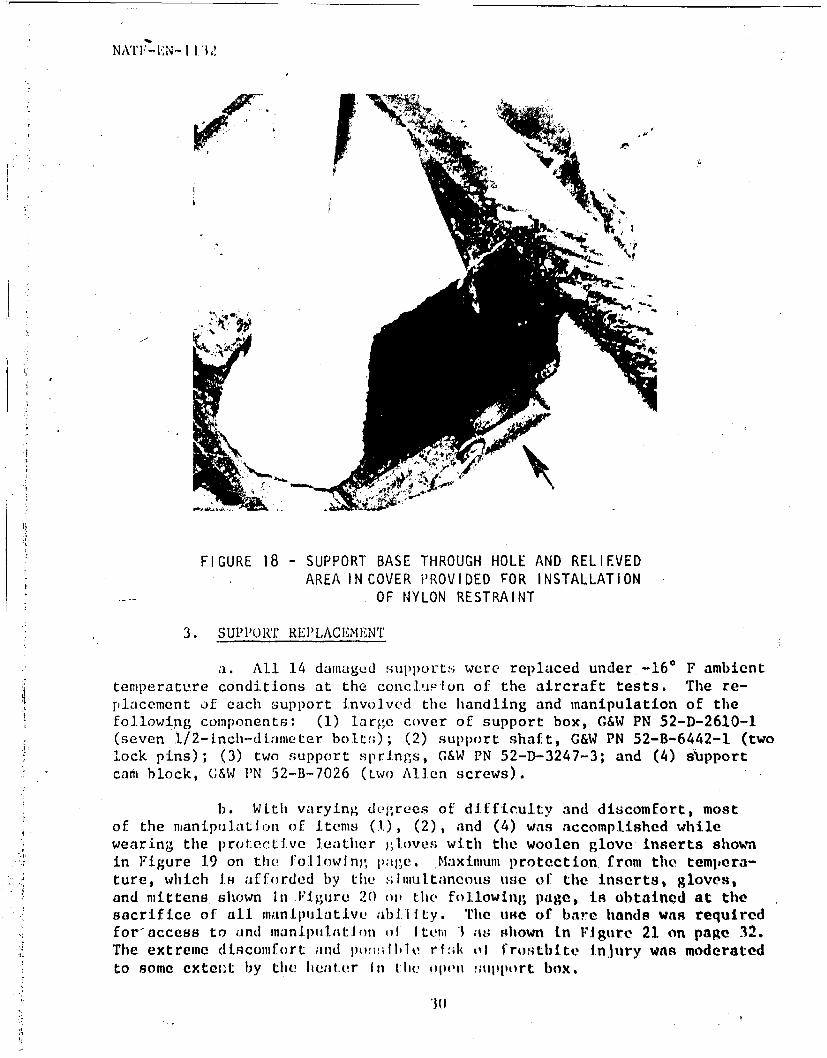
through hole in the metal frame base of the support block. The throughhole is aligned with the reliev!ed ara of the cover as bhown in Figure18 on the following page. It was asimple t-sk to place a loop of nyloncord (ends fused) over the hook cable on one side of the supp~ort, pullthe loop ends through the hole to the opposite side of the support witha pieca_ of heavy safety wire, and then tic the loop ends around the hookcable.
b. It was origin,1ly' planned to use the nylon restraints onthe BAK-14 supports for all the aircralL t t-Sts. Aftcr experiencing the
however, it was decided to remove the nylon restraints after the initialsix test events. During the remaining events, the hook-cable-retentiont capability of the supports (without restraints) at low temperature condi-tions was evaluated. Visual observation indicated that the hook cable
j was retained by the supports during the Ianding'- ,ear-trample portion ofthe reinainin- 12 events; however, it L ppe r,; advi sabl e to ins tallI nV lonrestraints on those supports damaged in thet hook-cable-retent ion are".
*~O NYLON~- RESTRAINT
3. sppOF NYLON RESTRAIN
a. All 14 damiaged supports were replaced under, -16* F ambienttemperature conditions at tile coticluz-Ion of the aircraft tests. The re-placement of each support Involved the handling and manipulation of tilefollowing components: (1) large cover of support box, G&W PN 52-D-2610-1(seven 1/2-inch-diameter bolts); (2) support shaft, G&W PN 52-B-6442-1 (twoLock pins); (3) two support springs, G&W PN 52-D-3247-3; and (4) suipport
* cari block, G&W 1'N 52-B-7026 (Lwo Alien screws).
1). WLth varying degrees of difficulty and discomfort, mostof the nianiptil.at I of Items (1,), (2), and (4) was accomplished whilewearing the protective leather gljoves with the woolen glove inserts shown
* in Figure 19 on the foll1owing page. Maximum protection, from the tempera-ture, which li4 afforded by the ,iniuttancous use of thle inserts, gloves,and mittens. shown In Figure 20) ov the following page, is obtained at the
sacifie o al inipulative abilty. Tile ufse of bare hands was requiredfor access to and manipulation of Item 1 ais shown in Figure 21 on page 32.The extreme discomifort and po~Iuerfd hlo.tieinuyWs oe.c
to sme eteutby the Iiau~iir Ini thle openi !,;jItjport box.to~~* soe(xtn

LID, FIUR 1Ar CA BLOC
INTALAIO AND
-2 AATE-AI EOA
A FIGURE 19
INSTALLATION AND
fr~.% TE AE PREMOVAL
~" c-174
va FIGURE 20
NATF-EN-1132
.1 iI v 4 -MT - Y E - ,
IJI
W--
4. LATCH-SPRING REPLACEMENT: Because of the inaccessibility of:!
1the spring attachment roll pins, the half loops on the ends of the spring" i were distorted to facilit-t installation around the roil pins. It was
- ~necessary to remove the protective gloves in order to r..anipulate the spring t~and the installation too,' (needle-nose pliers). Removal ol' the roll pins i
as an alternate means of installation was not attemptel The method used"-" by the contractor for the initial installation of the prjr,s is not known.
-5. SUPPOR' -BLTOCr LATCH iDJUSTMENT: The large cover plate and its= seven i/2-inch-diameter bolts must be removed from the support box inj. order to gain access to the support-block latch adjustment. The adjust-
:;, ment device consists of a bolt/dual jam nut arrangement by which the wire-p rope assembly, G&W PN 52-B-7024-1, is shortened or lengthened. To make~this adjustment, maintenance personnel must remove their gloves. The
I-% length of the wire rope is critical for proper latch operation: if the: wire rope is too long, the latch will jam; if too short, the latch will. not lock. Tension is retained in the wire-rope assembly when the support: arm is actuated by the air cylinder. The support arm, however, is designed' to move (swing) independently of th~e air cylinder when the hook cable is
., trampled by the aircraft or the support is impacted by the aircraft tire.- - When this occurs, the tension is released from the wire-rope assembly when-- the arm goes down and then is suddenly recovered when the arm returns to
32
-4, 2,

- . . . ..... .... ..... .... V- -.- ',-'. ..- _ . -' ' - - -- - , .. - : ° ,
NATF-EN-1132 -
the up position. It is possible that repetitive tension recovery is suf-ficient to cause the wire-rope assembly to stretch and/or pull throughthe retaining plate, G&W PN 52-B-7018. Seven latch adjustments were re-quired during the tests: five during replacement of the supports after
the aircraft tests; and one prior to each 50-cycle test.
6. MACADAM MATERIAL: The trough and the inside of the supportboxes were heavily coated with macadam material loosened from the run-way surface. It was a nuisance that hindered inspection because themacadam covered all exposed parts. Sufficient accumulation could jamthe latches or clog the drain opening in the support box.
7. CONCRETE FOUNDATIONS: Figure 8 on page 16 shows lateralcracks in the concrete foundation of the BAK-14. These cracks werevisually observed prior to conducting the tests. It is highly probable
tnat additional cracks may result from further seLtling of the foundation. - -
8. AIRCRAFT: The F-4E aircraft was not damaged during the test-ing. A routine nosewheel tire ch:-;, was necessary after the sixth testevent because of excessive tread weir.
'"A
V RELIABILITY
A. Although the confidence level is low because of the small sizeof the data sample, reliability was calculated to mathematically de-scribe the operational suitability of the BAK-14 retractable hook-cablesupport system in naturil low-temperature conditions. Reliability wasbased on actual failures which occurred during tests. The reliabilityfunction of the geometric probability distribution as recommended inreference (h) was used. The formula is:
Rg (k) (I-
where Rg (k)= The reliability at (k) cycles of any test sequence
and (h) = The estimated mean number of cycles between failures
B. When the estimated mean number of cycles between failures of thesupport latch mechanism is 51, the cyclic (raise/lower) reliability ofthe BAK-14 system is (.9 80 )k as follows (see next page):
Ref: (h) NAVAIRTESTFAC Report No. NATF-COS-3 of 22 Dec 1972: AnalyticalTechniques for Cyclical Equipment Exhibiting Reliability Growth
33
- '" --- ,
A NATF-EN-1132
k Rg (k)
(Cycles) (Reliability) iI)10 .81720 .66830 .54640 .446I,50 .364
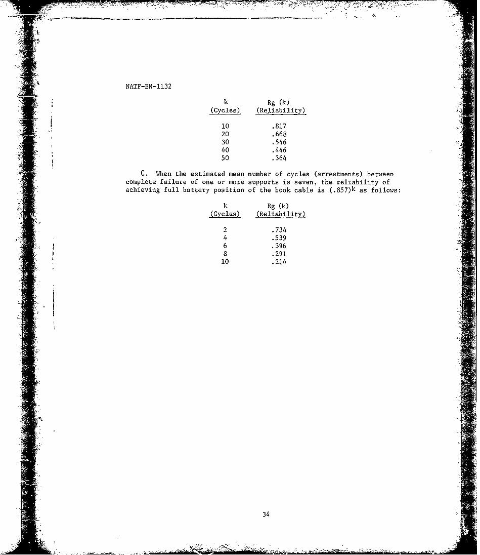
C.When the estimated mean number of cycles (arrestments) betweencomplete failure of one or more supports is seven, the reliability ofachieving full battery position of the hook cable is (.85 7)k as follows:
k Rg (k)(Cycles) (Reliability)
.7344 .5396 .3968 .29110 .214
34

7F-A '- ~ -r-- -
NATF-EN-1132
VI CONCLUSIONS
A. The BAK-14 retractable hook-cable support system is not suitablefor use in low-ambient temperature conditions because of the structuralfailure of the cold-hardened neoprene rubber of the support block, andthe related failure and high maintenance requirement of the support-blocklatch actuating mechanism during aircraft engagements. (Section IV, para-graphs Blb and C5)
B. CYCLIC PERFORMANCE
1. The cyclic ability of the BAK-14 system was unsatisfactory.(Secti on IV, Paragraph B2a)
2. The load of the tensioned hook cable had no effect on thesystem cycle time (raise 13 seconds, lower 7 seconds) because cycle timeswith and without the hook cable installed were the same. (Section IV,Paragraphs A3c and B2b)
3. The 20-second cycle (raise/lower) time of the system exceedsthe Air Force maximum time requirement by five seconds. (Section IV,Paragraph B2b)
C. Functional checkout of the BAK-14 control system was satisfactory.(Section IV, Paragraph A3)
0 . HEATER SYSTEM
1. The temperature survey confirmed that all support-box and
trough heaters were operating except the defective trough heater betweensupport boxes 2 and 3. (Section IV, Paragraph Al)
2. Operation of the cross-runway drain heaters was not confirmed.(Section IV, Paragraph Ale)
3. Visual observation during the test period indicated the troughheaters maintained the system free of ice at -36' F ambient temperatureconditions. (Section IV, Paragraph B2d)
4. The formation of moisture (frozen condensate) on the un'>.r-side of the support-box covers may contribute to the corrosion of com-ponents within the support bcx. (Section IV, Paragraph Alf)
-5. The heater continuity check circuit operate/test switches areincorrectly wired. (Section IV, Paragraph Alg)
6. The relays activated by each heater continuit o check circuitopetate/test switch are defective in the test position. t-.ection IV,Paragraph Alg)
35
mm~i.mmm m Ii m -
NATF-EN-1132
E. The BAK-14 was not damaged when trampled by the aircraft landinggear. (Section IV, Paragraph Bla)
F. SUPPORT BLOCKS
1. The sunport blocks were not damaged when the hook cable wastrampled by the aircraft main gear. (Section IV, Paragraph Bla)
2. The neoprene rubber support blocks were unsatisfactory becauseof their hardened condition at the low ambient temperatures. The loads
imposed during arrestments caused partial to complete separation of the14 Diocks from their bases. (Section IV, Paragraph Blb)
3. Although a previously damaged support separated from its baseas a result of arresting-hook impact, the arre~tment was successful.(Section IV, Paragraph Cl)
4. Installation of the hook cable in the retention hole of the Isupport block was difficult and time consumingdue to the hardened con-dition of the neoprene rubber at the low ambient temperatures. (SectionIV, Paragraph Cl)
5. The nylon-restraint and pivot-shaft through holes seriously
weaken the base of the support. (Section IV, Paragraph Blb)
- G. HOOK-CABLE RESTRAINTS
1. The ,ylon restri.ints are subject to failure. (Section IV, :Paragraph Bla)
2. Installation A' the nylon cord restraints was easily accom-:plished. (Section IV, Paragraph C2) 1
3. Although nylon cord restraints are not required at low ambient
temperatures because of tl-e increased hook-cable retention capability ofthe supports, they should be installed on those supports that are damagedin the hook-cable entry slot area. (Section IV, Paragraph C2)
H. SUPPORT-BOX ASSEI'BLY
1. The self-tapping attachment screws, G&E PN 52-E-768-36, of thepivot shaft brackets are unsatisfactory. (Section IV, Paragraph Blb(3))
2. The alignnont of the pusher block with the forks of the sup-port am offset yoke w.s no, maintained during the engagements. (SectionIV, Paragraph Blb(3))
3. The laitch ex-tn-ion springs, t;&' PN 52-C-3247-3, dislodgedduring the engagement-; an'; are unqatisfaictorv. (Section IV, Paragraph
SBlb(4))[it
- !774
NATF-EN-1132
4. At certain stages of support replacement, latch spring re-placement, and latch adjustment, maintenance personnel must remove allhand coverings in order to handle parts at very low ambient temperatures.(Section IV, Paragraphs (3', C4. and C5)
5. LaLh mechanism adjustments (1 per each 50 cycles) arenecessary because the wirc-tape stretohes and/or slips in the retainingplate, (Section IV, Paragraph C5)
6. Latch mechanism adjustments are time consuming because thelarge cover plate must be removed from the support box. (Section IV, "Paragraph C5)
7. The support-.arm mercury switches were either defective orincorrectly reinstalled fclowing aircraft tests. (Section IV, Para-graph B2c)
I. Cracks have develcped in the concrete foundation of the BAK-14.(Section IV, Figure 8 and Paragraph C7)
J., The F-4E aircraft was not damaged during the tests. (SectionIV, Paragraph C8)
37
.--------------
-.- , *

'--
4
NATF-EN-1132
VII RECOMMENDATIONS
A. SYSTEM CYCLE TIME: To improve system cycle time, install a quick- JT
exhaust ':alve in the air supply line at the three-way solenoid valvelncation.
B. HEATER SYSTEM
7 1. Replace the inoperative trough heater and the improperlywired lights of the heater check circuit.
2. Replace the noisy heater test relays with relays of an im-proved design.
3. Confirm the operation of the cross-runway drain heater.
C. SUPPORT BLOCK: As possible means to decrease the support failures -
caused by engagements at low ambient temperatures, the following are sug-gested:
1. INTERIM CORRECTION: Remove the upper portion of the hook-cable
retention area of the supports. Test the modified supports in conjunction
with nylon restraints at moderate ambient temperatures (500 F to 800 F).
2. PERMANENT CORRECTION
a. Redesign and fabricate a support block with a suitablematerial that will maintain the necessary strength and toughness over theexpected operating temperature range of the BAK-14 system.
b. Increase the load-carrying cross section within the metalframe base of the support by eliminating the two through holes and by pro-viding other means for anchoring the rylon restraint and pivoting the support.
_k
D. SUPPORT-BOX ASSEMBLY
1. Coat all metal surfaces within the support box that are sub-ject to corrosion with corrosion-resistant paint, compound, or lubricant,whichever is applicable.
2. Replace the self-tapping attachment screws, which anchor thepivot shaft brackets to the support arm, with through bolts.
3. Furnish the pusher block with a positive guide to maintain Iits rotational alignment with the forks of the support-arm offset yoke.
38 -
-" -- -n
as the primary objective. Failing this, make possible problem areas ofthe design accessible so that gloves may be worn by maintenance personnel.
; o, 5. Redesign the latch extension springs to provide increased ::A. -.. ~reliability.
:-'<6. To improve the performance of the latch-actuating mechanism,
". ::; the following are suggested: -
,% a. Interim Correction
' " (1) Improve the retaining plate anchor of the wire-rope. f -assembly and install a device to eliminate shock loading in the wire rope.
(2) Provide an access hole in the large cover of the sup-4port box to allow adjustment of tht see old rope without removing the cover.
b. Permanent Correction: Redesign the latch-actuating mechanism.(1) Improvethto eliminate the wire-rope assembly. l a r ho
-, E. Thoroughly exafhine BAK-14 concrete foundations for defects.
II
A,
39

77 7 77 7;--77,-
NATF-EN-113 2
VIII REFERENCES
(a) NAVAIRSYSCOM msg 022118Z jar 1974: Cold Weather Testing of BAK-14Galena Alaska
(b) NAVAIRTESTFAC Report No NATF-EI-108 of 31 Aug 1964: Evaluationof Retractable Pendant Supports for the Federal Aviation Agency
(c) Air Force Systems Command, Aeronautical Systems Division, Tech-nical Report No ASD-IR-69-1 of Aug 1969: BAK-14/F32 RetractableCable Support System
(d) Air Force Systems Command, Air Force rlight Test Centei, TechnicalReport No. FTC-TR-72-41 of Mar 1973. Testing of the BAK-14 Rptract-able Cable Support System
(e) NAVAIRTESTFAC Report No. NATF-E:.-ll128 of 22 Jan 1974: Evaluationof the BAK-14 Retractable Hook-Cable Support System
(f) Research and Development Center, Gulf & Western Industrial Pro-ducts Company: P-3986, Manual for Operation, Maintenance & In-stallation of BAK-14 Hck Cable Support System; P-3987, Parts &Drawing Lists
(g) NAVAIRENGGEN Test Directive No- MTSC-337 of 8 Nov 1973: BAK-14Cold Weathez Tests P!- Galena AFB. Alaska
(h) NAVAIRTESTFAC Report No NAIF-CCS-3 of 22 Dec 1972: AnalyticalTechniques for Cyclica'l Equipment Exhi~biting Reliability Growth
'40
NATF-EN-1132
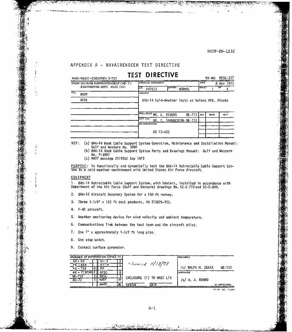
APPENDIX A -NAVAIRENGCEN TEST DIRECTIVE
TEST DIRECTIVE4 ND- NAEC-2O3O(REV 3-72) TD NO. MISC-337FROMK DIVISION SUPERINTENDENT (NE-7) PROBLEM ASSIGNMENT DATE 8 Nov 1973
ENGINEERING DEPT. NAEC (SI) .. 471 OML H
TO: NAFSUBJECT
AFSC BAK-14 Cold-Weather Tests at Galena AFB, Alaska
RO.GRMR. C. RIVERS NE-713 REV DATE INIT
UE N.MR. C. SAMfIUCHINO NE-732 _____
__________________________________AUTHORIZATION[* -
REF: (a) BAK-14 Hook Cable Support System Operation, Maintenance and Installation Manual:Gulf and Western No. 3986
(b) BAK-14 Hook Cable Support System Parts and Drawings Manual: Gulf and WesternNo. P-3987
(c) MATF message 211956Z Sep 1973
PURPOSE: To functionally and dynamically test the BAK-14 Retractable Cable Support Sys-*einTa cold weather environment with United States Air Force Aircraft.
EQUIPMENT
I. BAK-14 Retractable Cable Support System, with heaters, installed in accordance withDepartment of the Air Force (Gulf and Western) drawings No. 52-E-77Oand 52-E-900.
2. BAK-12 Aircraft Recovery System for a 150 ft runway.
3. Three 1-1/4" x 153 ft deck pendants, PM 512875-153.
4. F-4E aircraft.
5. Weather monitoring device for wind velocity and ambient temperature.
6. Connunications link between the test team and the aircraft pilot.
7. One I" x approximately 1-1/2 ft long pipe.
8. One stop watch.
9. Contact surface pyrometer.
NUMBER OF INFORMATION COPIES TO PREPARED
NE- 39__ NI-2 4A?( i/ /3 //RLP-~E -632 _ NI-4 1131JE -732 4 NF /s RLP M. ZECCA NE-732
NE -71 3PM) T AFSC 4 APPROVED
NNT-73R ENCLOSURE (1) TO NAEC LTR /sI.'.RAB
NATF X T A DATE .BY DIRECTIONi
PI ATE NO. 15306
A-1

14~~~ 777N-_T77,P F- - 777,7"5:
NATF-EN-1132
TO NO. MISC-3378 Nov 1973Sheet 2 of 4
_TEST PROCEDURE
Phase I: A prefunctional inspection is to be performed to insure that the system is readyto be tested. The following items are to be checked: 4
1. Record the "Support Box", "Trough" and "End Trough" heater power settings.
2. Record the surface temperature at each support box, and at points one and two feetfrom each support box along the trough.
3. Record the temperature in the trough at seven-foot intervals between the last sup- Mport box and the end of the trough.
4. Check that the inlet and delivery pressures of the regulator, G&W PN 52-C-3861,read 3000 PSIG and approximately 100 PSI'O. The delivery pressure should read between thered lines on the pressure gage.
Phase IT: A functional test is to be performed to determine that the system is operation-ally sound for aircraft tests. References (a) and (b) will be used for operating instruc-tions. The following tests will be required:
I. Press to test all lights oa the Tower, Runway and heater control boxes to insurethat the lights illuminate. Replace faulty bulbs.
2. Heater continuity, circuit check
(a) Turn on the heater support l3x test switch and the heater support box circuitbreaker. The support box heater test iight should illuminate. An unlit light indicatesan inoperative heater. Since the heaters were checked during Phase I when the temperaturereadings were taken, an unlit light indicates a faulty circuit.
(b) Rotate the support heater continuity selector through all the support box po- Isitions. Check the test light at each position.
(c) Return the heater support box test sv:itch to the "off" position.
NOTE: When the heater support box, trough, and end trough test switches are turned on,no heat is being provided. Therefore, these tests must be conducted as rapidly as pos-sible, and the test switches returned to the "OFF" position.
(d) Repeat the above test for *he trough and end trough heaters using their appro-priate test switches.
3. Limit Switch Continuity Check
kAV (a) Place the Tower/Runway switch located on the tower control box in the "Runway"position.
(b) Place the Up/Down switch on the runway edge control box in the "UP" position.shu tThe "UP" light should illuminate.
(c) Rotate the limit switch continuity test selector, located on the malfunctionlocator box in the tower, through all the positions. Check the "UP" light each time. Anilluminated light indicates that the limit switch is properly closed.
(d) Repeat the test with the Up/Down switch in the "Down" position.
Ai-i~k A-;2

NATF-EN-1132
TO NO. MISC-337ht 8 Nov 1973
Sheet 3 of 4
4. Tower/Runway Control Tests
(a) Place the Tower/Runway soitch in the "Tower" position.
(b) Activate the BAK-14 System. Record the time required to raise and lower thecable supports. Check that the "UP" and "Down" lights illuminate.
NOTE: It may be necessary to cycle the system once or twice to fill the system in or-j:7, der for all the supports to react at the same time.
(c) Insure that the cable supports cannot be activated from the runway edge controlbox while the Tower/Runway switch is in the "Tower" position.
(d) Place the Tower/Runway switch in the "Runway" position. The red Runway Permis-sive lights should illuminate on th tower control box, and the green Runway Control lightshould illuminate on the runway edge control box.
cable supports. Check that the "Up" and "Down" lights illuminate.
I(f) Place the Up/Down switch on the tower control box in the opposite position fromthat on the runway edge control box.
"Y_' (g) Return the Tower/Runway switch to the "Tower" position. The cable supportsshould react as directed by the tower control box. The red Runway Permissive and greenRunway Control lights are not illuminated.
Phase III - Dynamic Tests: Dynamic tests are required to evaluate the performance of theBAK-14 Retractable Cable Support System. Existing weather conditions will prevail.
1. The cable supports will be cycled 100 t1mes to verify the system reliability.Fifty of these cycles will be originated at the to,.er control box and the remainder will,
4 <'be initiated at the runway edge control box. -
2. The BAK-14 system, will be subjected to total of 12 rollovers by the main landinggear of an F-4E aircraft. The rollover tests will be as follows:
(a) One rollover with the main landing gear passing between the cable supports willbe conducted at taxi velocities of 60, 80, and 100 knots.
V (b) A total of 9 rollovers (or until 3 supports have failed) with the main landinggear impacting a support will be conducted at a taxi velocity of 100 knots.
3. The BAK-14 system will be subjected to a total of 6 ircraft hook arrestments.
~ji<i! i (a) One hook arrestment, with the hook passing between two supports, will be con-itducted at taxi velocities of 60, 80, and 100 knots.
_ (b) One support will be impacted by the hook of the F-4E aircraft at a taxi veloc-ity of 100 knots until failure or a total of 3 hook impacts.
T1-4. The aircraft Pilot will determine flight operating conditions, minimum landing cri-
- . teria (OPHIAV3710.7G) arid safe run.iay conditions. It will be the aircraft pilot's discre-tion to brake, arrest, o; take-off in case of a missed engagement or equipment failure.
:4-
FA-

-o 4
NATF-EN-1132
TD NO. MISC-3378 Nov 1973Sheet 4 of 4
5. The following inforiiation will be required for each rollover and hook arrestmen.:
(a) Aircraft indicated air speed
(b) Wind velocity and direction
(c) Ambient temperature--this will also be required during the cycle tests of thecable supports.
(d) Aircraft weight
(e) Condition of the cable supports
(f) Any difficulties encountered in placing the cable in the support blocks ortying the cable down.
6. After the above tests or after a support block has failed, the procedure for instal-ling a new support block will be evaluated.
PHOTOGRAPHIC COVERAGE
1. Still photographs will be required of any equipment failure or possible problem areas.
2. Two nigh-speed motion picture cameras will be required to cover BAK-14 components asrequested by the test director. These cameras will operate under limited light conditions,and at approximately 100 frames per second due to the weather conditions.
PARTICIPANT RESPONSIBIITIES
1. The Naval Air Test Facility will he responsible for directinj the tests, piloting theaircraft, and accident nd incident repoitirnq in accorda.,ce with reference (c).t 2. The Naval Air Engineering Center will monitor the tesfs.
3. The United States Air Forcc will be responsible for the following:
(a) Providing and maintaining the aircraft.
j ] (b) Providing billets, local climatic indoctrination, and weather clothing for USNSj ~personnel.
(c) Briefing thfe USN pilot on local area flight procedures.
(d) Operating, maintaining, and supporting the BAK-14 and BAK-12 systems.F"(e) Providing communications between the test team and the aircraft pilot.
(f) A temporary shelter near the test site for USN personnel.
1 '
-
A-4
. .. --- =:-
--Jc :$ - --- > -':+ .- - - "+' -- ,- ; "