TO - Defense Technical Information Center · THE ONE-DIMENSIONAL THEORY OF STEADY COMPRESSIBLE...
30
UNCLASSIFIED AD NUMBER CLASSIFICATION CHANGES TO: FROM: LIMITATION CHANGES TO: FROM: AUTHORITY THIS PAGE IS UNCLASSIFIED ADA801398 unclassified restricted Approved for public release; distribution is unlimited. Distribution authorized to DoD only; Administrative/Operational Use; JUL 1947. Other requests shall be referred to National Aeronautics and Space Administration, Washington, DC. Pre-dates formal DoD distribution statements. Treat as DoD only. E.O. 10501 dtd 5 Nov 1953; NASA TR Server website
-
Upload
hoangkhanh -
Category
Documents
-
view
216 -
download
2
Transcript of TO - Defense Technical Information Center · THE ONE-DIMENSIONAL THEORY OF STEADY COMPRESSIBLE...

UNCLASSIFIED
AD NUMBER
CLASSIFICATION CHANGESTO:FROM:
LIMITATION CHANGESTO:
FROM:
AUTHORITY
THIS PAGE IS UNCLASSIFIED
ADA801398
unclassified
restricted
Approved for public release; distribution isunlimited.
Distribution authorized to DoD only;Administrative/Operational Use; JUL 1947. Otherrequests shall be referred to NationalAeronautics and Space Administration,Washington, DC. Pre-dates formal DoDdistribution statements. Treat as DoD only.
E.O. 10501 dtd 5 Nov 1953; NASA TR Serverwebsite

NATIONAL ADVISORY COMMITTEE FOR AERONAUTICS
TECHNICAL NOTE
No. 1336
THE ONE-DIMENSIONAL THEORY OF STEADY COMPRESSIBLE FLUID
FLOW IN DUCTS WITH FRICTION AND HEAT ADDITION
By Bruce L. Hicks, Donald J. Montgomery and Robert H. Wasserman
Flight Propulsion Research Labortory Cleveland, Ohio
N AC A
Washington July 1947
^Ifw .;^s^

NASA Technical U
3 1176 014258017
NATIONAL ADVISORY COMMITTEE FOR AERONAUTICS
TECHNICAL NOTE NO. 1336
THE ONE-DIMENSIONAL THEORY OF STEADY COMPRESSIBLE FLUID FLOW
IN DUCTS WITH FRICTION AND HEAT ADDITION
By Bruce L. Hicks, Donald J. Montgomery, and Robert H. Wasserman
SUMMARY
Steady, diabatic (nonadiabatic), frictional, variable-area flow of a compressible fluid is treated in differential form on the basis of the one-dimensional approximation; The basic equations are first stated in terms of pressure, temperature, density, and Telocity of the fluid. Considerable simplification and unification of the equa- tions is then acbieTed by choosing the square of the local Mach num- ber as one of the variables to describe the flow.
The transformed system of equations thus obtained is first examined with regard to the existence of a solution. It is shown that, in general, a solution exists whose calculation requires know- ledge only of'the variation with position of any three of the dependent variables of the system. The direction of change of the flow variables can be obtained directly from the transformed equa- tions without integration. As examples of this application of the equations, the direction of change of the flow variables is deter- mined for two special flows.
In the particular case when the local Mach number M = 1, a special condition must be satisfied by the flow if a solution is to exist. This condition restricts the joint rate of variation of heating, friction, and area at M — 1. Further analysis indicates that when a solution exists at this point it is not necessarily unique.
Finally it is shown that the physical phenomenon of choking, which is known to occur in certain simple flow situations, is related to restrictions imposed on the variables by the fornTof the transformed equations. The phenomenon of choking is thus given a more general significance in that the transformed equations apply to a more general type of flow than has hitherto been treated.

NACA TN No. 1336
INTRODUCTION
The rational experimental development of Jet- and rocket- propulsion power plants requires adequate knowledge of the theoreti- cal mechanics of diabatic (nonadiabatic), frictional, variable-area compressible fluid flow. The differential equations describing this typo of flow are well known. (See, for example, references 1(a), 1(b), 2, 3, and 4.) Their solution in the three-dimensional case, however, \B so difficult that some simplification is necessary to permit development of the theory in a form immediately useful for technical applications.
In the present paper, such simplification is effected by gen- eralizing the familiar "one-dimensional" or hydraulic treatment of fluid flow to include the simultaneous effects of heat addition, friction, and area change upon the flow of a compressible fluid rather than by attempting to show that the one -dimensional .approx- imation follows from a simplification of the hydrodynamüc and heat- flow equations in their general three-dimensional form. The Gen- eralization leads to one-dimensional equations in differential form, which are identical with equations previously used by other inves- tigators in less general cases.
Generalized conservation equations have been derived in appen- dix A in order that a complete and logical basis for the theory may be accessible to the reader. The resulting theory is intended to serve as a foundation in differential form for calculatxon of all types of mathematically continuous (that is, shocklcss) flow of per- fect gases to which the one-dimensional approximation is applicable. Thus the theory applies directly to compressible flow in combustion chambers and also, with but slight modification, to flow in turbines and compressors (cf. reference 5) and nozzles and diffusers whenever the one-dimensional approximation is valid.
In order to obtain convenient and unified equations, the gen- eralized relations are transformed by introducing a new basic variable, the square of the local ilach number M* S. if. pressure and temperature are chosen as the additional basic variables; other relevant flow variables (for example, density, velocity, mass flow) may be expressed in terms of Mach number squared, pressure, and tem- perature. Values of M from zero to infinity are considered; the treatment is therefore applicable to-both subsonic and supersonic flow.
NACA TN Wo. 1336
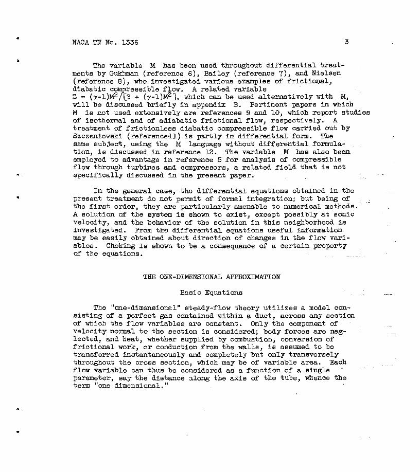
The variable M has been used throughout differential treat- ments by G-ukhman (reference 6), Bailey (reference 7); and Nielsen (reference 8), who investigated various examples of frictional, diabatic compressible flow. A related variable Z = (y-l)R2f{2. + (7-l)M2], vhich can be used alternatively with M, will be discussed briefly in appendix B. Pertinent papers in. which M is not used extensively are references 9 and 10, which report studies of isothermal and of adiabatic frictional flow, respectively. A treatment of frictionless diabatic compressible flow carried out by Szczenioweki (reference-ll) is partly in differential form. The same subject, using the M language without differential formula- tion, is discussed in reference 12. The variable M has also been employed to advantage in reference 5 for analysis of compressible flow through turbines and compressors, a related field that is not specifically discussed in the present paper.
In the general case, the differential equations obtained in the present treatment do not permit of formal integration: but being of ^ the first order, they are particularly amenable to numerical methods. A solution of the system is shown to exist, except possibly at sonic velocity, and the behavior of the solution in this neighborhood is investigated. From the differential equations useful information may be easily obtained about direction of changes in the flow vari- ables. Choking is shown to be a consequence of a certain property of the equations. . *.
THE ONE-DIMENSIONAL AFPE0XIMATI0N
Basic Equations
The "one-dimensional" steady-flow theory utilizes a model con- sisting of a perfect gas contained within a duct, across any section of which the flow variables are constant. Only the component of velocity normal to the section is considered; body forces are neg- lected, and heat, whether supplied by combustion, conversion of frictional work, or conduction from the walls, is assumed to be transferred Instantaneously and completely bi\t only transversely throughout the cross section, which may be of variable area. Each flow variable can thus be considered as a function of a single parameter, say the distance along the axis of the tube, whence the term "one dimensional."

4 NAOA TW No. 1336
The conventional variables — pressure, temperature, density, and velocity in one-dimensional flow — are connected by four rola- tions derivable from the first law of thermodynamics, the conserva- tion of mass, the second law of motion, and the thermal equation of state for a perfect gas.
The four relations are:
Conservation of energy Cp dT + VdV = dQ (1)
Conservation of mass d(pVA) = 0 (2)
Equation of motion -dp =* pYdV + pdP (3)
Equation of state d(p/RpT) =0 (4)
The specific heat at constant pressure Cp and the gas constant E do not vary in the flow. The sy&ibols p, Y, p, and T, respec- tively, stand for density, velocity, absolute static pressure, and absolute static temperature. The pipe area, which may be variable, is represented by A. Heat added per unit mass is indicated by Q, and work per unit mass done against friction by E. Consistent units are used throughout. In equations (1) through (4) each vari- able* is to be considered as a function of a single parameter, such as the distance x along the tube considered positive in the direc- tion of flowj and, of course, the meaning of each differential du is then given hy
du = u'(x)dx
Equations (1) to (3) are customarily used without explicit recoJJgnitlon of their true meaning with regard to the one-dimensional approximation. The interpretation of the quantity dF in particular is often obscure. In order to provide a logical, unified basis for the theory, equations (l) to (3) are derived in app&ndix A; spocial care is taken to keep the derivations within the framework of the one-dimensional approximation. . T
Applicability
The validity of the one-dimensional approximation depends upon the assumption of the uniformity of flow conditions across a plane normal to the direction of flow. Experience has shown that this

NACA TIT No. 1336
assumption constitutes an adequate approximation in many special cases; in particular, with subsonic turbulent flow in long pipes without separation, the .reasonably flat velocity profile permits the use of equations derived on this basis. In cases involving incomplete growth of boundary layer or where separation of flow occurs, however, there is grave doubt as to the applicability of a one- dimensional treatment. Although boundary-layer effects are somewhat amenable to calculation, the occurrence of separation is difficult or impossible to predict and the question of applicability must usually be determined by experiment or estimated by experience.
The one-dimensional approximation would not be valid if oblique shocks occur in the flow. Nor can normal shocks, if treated as flow discontinuities, be handled in the differential form of the present approximation. If, however, in equations (l) and (3), dQ and dF are considered to depend upon the derivatives of T and T and if heat and momentum transfer in the direction of flow is allowed, then the equations for continuous normal shock (reference 1(c), p. 219) can be put in the form of equations (1) to (4).
In the development and use of equations (1) to (4) verious approximations are made, such as neglecting the squares of velocity components normal to the direction of flow, replacing the square of the cosine of the half-angle by unity, and assuming the constancy of R and Cp. In this paper no attempt is made to state under what circumstances such approximations are suitable.
TRANSFORMATION OF EQUATIONS
Change of Variables
A canonical form for equations (1) to (4) is obtained by taking logarithmic derivatives and choosing as a variable the square of the local Mach number
M2= N = V2/7RT (5)
where y is the ratio of specific heats. This choice to obtain simplification of the equations is not unique; similar advantages result with other dimensionless combinations of velocity squared and a temperature. For instance, some workers have used the ratio of dynamic temperature to total •cemperature; in appendix B of the present report are presented the canonical differential equations in terms of this variable.

NACA TN No. 1336
If equations (1), (2), (3), and (4) are divided by cpT, pVA, p, and P/RPT, respectively, there result—
V2 dV dT dQ (7_D 7RT V T cpT
dY dp dA
T + — P
rs " T
V2
7 yM
dV dp + —
P =
"p~
dp —. + p
dT dp
"T* p - 0
(6)
(7)
(8)
(9)
With use of equation (5) and the expression for dV/V obtained by logarithmic differentiation of equation (5),
dV
V 2 V N T /
and, upon elimination of dp/p, there are found
1/dN dT\
" 2V¥" + "~ - (10)
(7-l)N dN
N 1 +-
(7-l)N dT dQ
CpT = de (ii)
1 dN dp 1 dT dA__
2 N TT ~ 2 ¥~" ~ T~ (12)
7N dN dp yS dT dJ
2 N ET = du (13)
where the dimensionlese quantities d9, da, and du have been introduced to simplify the following analysis.

KACA TN No. 1536 7
Solution for Logarithmic Differentials
If the determinant formed by the coefficients of &N/N, dp/p, and dT/T in equations (11), (12), and (13) is not identically zero, the equations may he solved uniquely for these, three differentials. As the determinant in question is proportional to (l-N), -which vanishes only for N = 1, the solution is obtained as follows:
dN/N = (l-N)" f(l + 7N) d9 + j*2 + (y -1)N] du + f_2 +(7-1)N] da J (14)
dp/p = (l-N)" "^- 7N de - [l +(/-1)N]- du - 7N da | (15)
dT/T = (l-N)"1 | (I-7N) d0 - (7-l)N du - (7-l)N da } (16)
It is also convenient to record the differential expressions for the density p and velocity Y:
dp/p = dp/p - dT/T = (l-N)"1 (-de - du - N da) (17)
dV/V = (dN/N + dT/T)/2 = (l-N)" (de + du + da) (18)
Application of Second Law of Thermodynamics
The first law of thermodynamics was used in the formulation of the basic equations; the second law of thermodynamics may be employed to furnish additional information. The entropy differ- ential dS for a perfect gas is given (cf. reference 13,* p. 63) by
dS/cp = dT/T - [(7-1) H\ dp/p = de + [(7-l)/7j du (19)
The second law of thermodynamics then states . .
0^ dS/cp - dQ/cpT = [(7-1) /7] du (20)
The relation, according to equation (19), that
dS/c = (de + du + da) - du/7 -da
when used with equation (20), results in the inequalities
de= dS/c = dß - du/7 - da = dß -da (21)
where dß = - de + du + da.

NACA TN No. 1336
DISCUSSION OF EQUATIONS
Remarks on Integration of Equations
Equations (14), (15), and (16) can be rewritten as
N 1+7N N 2+(7-l)N N 2+(7-l)N _ . N' = '— Qi + Li i_.pi - Li i- A' (22)
1-N c1DT 1-N ET 1-N A
P* = ___. 2_L Q,_ ___. l+(7-QN -., _P_ 2f A« (23) 1-N c T 1-N ET 1-N A
P T I-7N T (7-l)N T (7-l)N
—s- Q' - T--S T^T, • F4- -r-g • ; — A' T' = — 0' — — F'+ -—-—i-— A' (24) 1 T^N cpT * 1-N ET r - 1-N A ^ ;
where the primes indicate differentiation with respect to x. This system clearly satisfies, except at N = 1, the conditions of the fundamental existence theorem (see, for example, reference 14) when Q, F, and A are differentiable. Hence a solution exists except at sonic velocity and may "be obtained formally when possible, and by standard numerical methods otherwise, as soon as the functions Q, F, and A (or their derlvatires) are specified. More gener- ally, the system may bo solved in similar fashion for any throe of the variables N, p, T, Q, F, and A as functions of xt when the variation with x of the other three is prescribed. Also it may be noted that as all the foregoing variables are functions of one parameter, any two may be considered as functions of each other under suitable circumstances.
Direction of Change of Flow Variables
In practical as well as in theoretical work it is frequently useful to be able to determine the direction of change of flow quantities with respect to heat addition, friction, or area varia- tion without troubling to get quantitative information from inte- grated forme. Equations (14) to (18) (or (22) to (24)) permit the specification of signs of derivatives _at any particular point and also throughout certain regions of flow. Thus equation (14) shows that in subsonic flow the effect of positive 01, \i', or a', is to increase N, whereas for supersonic flow the effect is to decrease N. When the derivatives have different signs, the net effect will depend upon the algebraic sum of the separate con- tributions.

NACA TUT No. X336 9
As an example of the use of this technique, suppose heat is added to a fluid in a constant-area pipe, with negligible friction; that is, 01 ^ 0, u' =« a' = 0. It is easily seen from equa- tions (14) to (18) that for the entire range of W from zero to infinity
(1-Hf) dN/dQ ^ 0 (25)
dp/dtt = 0 (26)
(1-7N)"1 dT/dN = 0 (27)
dp/dN ~ 0 (28)
dV/dN = 0 . " -.(29)
These results are given in reference 12. By use of the chain rule for the derivative of a function of a function, the sign of the derivative of any of the flow variables with respect to any of the others may "be obtained; thus, from equations (25) and (29) it is clear that
dV dV dW > , (1"H> dQ - (1-H) dH 3Q - ° (30)
As another example, consider the flow in circular cylindrical pipes with heat addition and with friction; that is, 0' 3? 0, li' =i. 0, a' = 0. (See also related discussion in reference 8.) Equation (14) will be used to determine the direction of change of N with respect to x. If the heat addition is only through the wall,, which is at temperature Tw, the heat added per unit mass of fluid in passing a distance dx along the tube is given by
pVA dQ = h (Tw-T) («D dx) (31)
where D is the tube diameter, and h the local surface-to-fluid coefficient of heat transfer, in heat units transferred per unit temperature difference, per unit area. (Cf. equation (2), refer- ence 15, p. 135.) In conjunction with equation (11), equation (31) leads to
d0 _ _*g _ h [(Tv/T)- l] jtD dx _4h C(Tg/T) - l] dx
CpT cp pVitD2/4 c pVD

10 NACA TN No. 1336
The expression for frictional work done Is assumed to be give*1 (cf. reference 15, p. 119, equation (8)} by
dF = fV2 dx
2(D/4) (33)
where f Is the Panning friction factor. From equations (13) and (33) it follows that
dF 2f?N dx /.IAS
If Reynolds' analogy is valid, h may be replaced by c« pYf/2 (reference 15, p. 162, equation (1)), whence equation (if) becomes
dN/dx = [N/(1-N)] ' (I+7N) [(Tv/T) - l] + [2+ (7-l)N.I 7N \_2ffa (35)
This equation may be used to determine the direction of change of N with x, and hence of other flow quantities, for various ranges of N and of Tw/T. For values of (TW/T) «1 (maximum rate of cooling), dN/dx is positive for values of
1 > N > j-7 +J~y{5y"^T) 1 /Z7(7-l) =0.58
for 7 = 1.4; that is, the effecte of friction in increasing tho Mach number overbalance the effects of the cold-walls in lowering it if 1 >M = vN> 0.76 for 7 = 1.4. If N> 1 then (dN/dx) < 0, and acceleration of frictional, supersonic flow by connective cooling appears to be impossible. Acceleration of frictionless supersonic flow by cooling should, however, be possible (refer- ence 12).
Behavior of Solution at Sonic Velocity
The differential equations (14) to (18) must be examined as to behavior at the singular point N = 1. In order that the logarithmic differentials may be defined at this point, it is neces- sary that dß = de + du + da vanish suitably at N = 1; that is,
dß =.d6 + du+dcx = 0 at N = 1 (36)
because each logarithmic differential is proportional to dß/(l-N) there. If dß ¥ 0 upstream of the end of the duct, N can equal

NACA TN No. 1336 11
1 only at the end of the duct. This situation ie illustrated "by the "choked" converging nozzle and by the frictional diahatic flow, which is treated in the previous section. Equation (36) is formally satisfied at the end of a duct where de, du, and da may be considered to vanish for all values of 3U.
Between the ends of a duct, however, dß must always vanish where N = 1. This condition shows that at N = 1 arbitrary varia- tions of dö, d|jL, and da are not possible. A specific illustra- tion is the ideal nozzle in which d© = &\i = 0; according to equa- tion (36), da is then restricted to the value 0, which means that the area has a stationary value at N = 1. This is the well- known result that sonic velocity can be attained only in the throat of an ideal nozzle in shockless flow. A quite similar treatment applies for the cases where d6 and du are the quantities to be investigated. (See pertinent material in references 5 to 12.) Condition (36), which was. necessitated "by the presence of the deter- minant (l-lT)/2 in equations (14) to (18) is thus seen to provide a unification of the treatment of the flow behavior in the neighborhood of sonic velocity.
Combination of the second law of thermodynamics with equa- tion (36) also yields limitations on the behavior of the flow at N = 1. According to equations (21) and (36), at sonic velocity
de ^ dS/cp ^ - da = dA/A (37)
These results may be stated in words to the effect that in converg- ing or constant-area channels at N = 1, neither the heat term do = dQ/cpT nor the entropy term ds/cp can be positive. In jdiverging channels these two terms may be either positive or neg- tative. If either de or du. is everywhere 0, relation (21) yields more detailed results. For example, if de 3F 0, then at N = 1, by equations (36) and (20)
djj. = -da
= [7/(7-1)] as/cp £ 0 (de = 0, N = 1)
Continuous flow with friction and without heat addition at sonic velocity cannot therefore occur in a converging channel (refer- ence 7).

12 NACA TN Mo. 1336
A more complete treatment of the behavior of the flow when N = 1. "between the ends of the duct is obtained by considering second-order terms. As N approaches unity, equation (14), which may be written
N'/N = 4(1+7N)0' + Of(7-l)N] u' + [2+(7-l)N] a' |/(l-N)
(where the prime indicates differentiation with respect to x.), takes the form o/O. For the evaluation of this limit, L'Hopital's rule gives after some calculation
V = [e0'N0' + (1+7) ßo"3 /(-No')
where subscript o denotes value of function at N = 1. The eolu- is
N0' = -0o'/2 ±/<0o'/2)2 - (l+7)ß0" (38)
tion for N0' is
The double-valuedness of the derivative at N = 1 wilL have impor- tant consequences in that a unique solution of the equations may not be obtained when N = 1 along the flow path. In general, it will be possible to continue the solution from N = 1 along either of two paths, depending on the choice of sign. In certain 'cases, depending on the signs of $0' and ß0", one sign will correspond to continuation into subsonic flow, the other into supersonic; otherwise the two choices will correspond to different continuations into flow of the same character. This result means that specifica- tion of initial conditions and of variation of de, du, and da alone is not suffioe*|I,nt to insure a unique solution if N becomes unity along the flow. In the event that the radicand is zero, it is possible that only one solution is obtained; or it may happen that some higher derivative is double-valued with resulting ambiguity of— solution. The analysis for this case is somewhat involved and will not be continued here.
It is interesting to note that a less general problem of the same nature has been presented by Lorenz (reference 16) and Prandtl and Proell (reference 17). Some of this work is possibly more accessible in reference 18.
The Phenomenon of Choking
The general equations (ll), (12), and (13) impose restrictions on the relations between the flow variables and the heat, friction, and area variation. When these restrictions take the form of upper

NACA TN No. 1336 13
or lower limits on mass flow, the associated phenomena are termed "choking" processes. As an example, it is well known that the ideal nozzle has for given subsonic entry conditions a maximum mass flow beyond which the discharge cannot be increased no matter how much the exit pressure is lowered. Another case is "thermal choking," wherein the entrance Mach number and hence mass flow in diabetic, frictionless, constant-area flow is limited for given heat addition despite indefinite reductions in outlet pressure (reference 12).
The nature of choking may be studied with the help of equa- tion (22), which was derived simply from the basic equations. It will be shown that unless heat, friction, and area variation are such that (l-N) times the right-hand side of equation (22) changes from positive to negative as x increases, the Mach number in the tube cannot become greater than 1 if the entrance velocity is subsonic and cannot become less than 1 if the entrance velocity is supersonic, provided that the flow variables remain continuous.
For convenience, designate by Y the factor (l-N) times the right-hand side of equation (22). The quantity Y is seen to con- sist of a sum of terms in Q', F', and -A' multiplied by func- tions of N that are always positive. (in the event that only one of the terms Q', F', and -A' is not 0, Y becomes merely the derivative of the heat added, the frictional work, or the area, multiplied by a simple function of the flow variables; then posi- tive Y corresponds to the case of heat addition, friction, or a converging duct.)
Suppose first that Y is always negative. Then if the flow at the entrance section x-^ is subsonic, dN/dx = (l-N)Y<0, and the Mach number decreases; if the entering flow is supersonic, dN/dx = (l-N)Y >0, and the Mach number increases.
Suppose now that Y is always positive. Then, if the entering flow at X]_ is subsonic, dN/dx = (l-N)Y>0, and the Mach number increases. But N cannot increase past unity as x increases. For suppose N = 1 at x = x0 and is greater than 1 in the right- hand neighborhood of x0 (exclusive of XQ); then dN/dx is nega- tive in this neighborhood, because (l-N) is less than 0 and Y is greater than 0. Now N is equal to unity at x = XQ, is contin- uous, and has a negative derivative in the neighborhood mentioned. Hence N is less than 1 in this neighborhood, which contradicts the assumption. Therefore N cannot be greater than 1 if Y is always positive, N is continuous, and N(x^) is less than 1. In general, no continuous solution exists for values of x > x0 if Y

14 »ADA TIT No. 1336
ia always positive. This statement, and tho foregoing proof, are valid even if N'(x0) does not exist. An analogous development may bo made for H(x^) greater than 1 with the conclusion that, with Y positive and N continuous, N cannot bo less than 1.
If Y changes from positive to negative at x = XQ, however, the value of N may cross unity at that point, but if Y is ini- tially negative, N goes away from unity as previously shown and can only turn toward unity if Y changes from negative to positive; this change must be made at some value of N other than 1. After Y has changed to positive, the situation reduces to the case that Y is always positive, with tho N where Y changes sign now taken as the entrance N.
It has been shown that up to same fixed point in tho tube, which can bo either the exit or the point at which Y changes from positive to negative, N and therefore the Mach number do not become greater than 1 if tho entering velocity is subsonic nor Ices than 1 if tho entering velocity ia supersonic. Furthermore, if Y is positive up to the point at which N is limited, the derivative of N before this point is always positive if tho entoring flow is subsonic and is always negative if the entering flow is supersonic. Thus, for positive Y and subsonic entrance velocity the ontranco N cannot exceed some limiting value less than 1 determined by the particular Q, F, -A variation, for N is alwajs increasing from its initial jsaluo and cannot exceod 1; and, by analogous con- siderations for positive Y and supersonic entrance velocity, N cannot be less than some limiting value greater than 1. This limitation is essentially tho choking phenomenon.
The spocific form this limitation takes is not easily stated in the general case, bocause the choice of which factors are to.be held constant and of which variablos are to be considered limited determines the particular form of the restrictions. Numerical results for some-particular cases are given in reference 12, amon£ others, to illustrate' the nature of possible results. It is felt that additional special cases should be investigated before a thorough study of the general case is attempted.
Flight Propulsion Research Laboratory, . National Advisory Committee for Aeronautics
Cleveland, Ohio, February 24, 194?.

HACA TN No. 1336 15
APPENDIX A
DERIVATIONS OP TB3EE BASIC EQUATIONS
Conservation of Energy
The first lav of thermodynamics applies to energy changes between two states of a system enclosed within a surface» Let the system (fig. 1) he the gas of mass Am that is contained in the
x = 0
Figure 1
initial state within the tube walls and the sections at x^_ and i, and in the final state within the tube walls and the sections at £j_ and £2; xl* z2> ani £l ^re arbitrary, ana |2 is determined by the condition that the mass between x^ and £ -^ equal the mass between x2 and f; 2. When m(x) is defined as the
total mass of gas contained within the duct between the sections x = 0 and x = x, the definition of Am becomes
Am=m(x2) - m(x1) =JH(I2) - m^) (33)
Let U(x) denote the internal (thermal) energy per unit mass of fluid, p(x) the static pressure, V(x) the gas velocity,

16 NACA TN No. 1336
A(x) the cross-sectional area of the. duct, each.-taken at the .sec- tion, xj and Q(x) the heat (In mechanical-energy unite) added from walls or by combustion^- to a unit mass of the fluid during its passage from x = 0 to x = x. Then the first law of thermodynamics says for steady flow that
(U +i V2)dm - ('U-+i V2) m(tx) ^ 2 > JmCxL) V 2 '
dm =
'm(il) Q dm pA dx
*2
Q dm
(40)
As A dx = (l/p) dm, where p(x) is the density of the gas, equa- tion (40) becomes
rm^2> /i ? \ fmUi> / i ? (u + I V2 - Q + p/p) dm = (u +i V2
Jm(x2) V 2 y Jm(xx) V 2
when the limits of integration are changed.
Q +• v/p) dm
(41)
Provided that the integrand is continuous (which requirement excludes shock), the expression on the right-hand side of equa- tion (41) may be written, by the theorem of the mean for integrals:
[mÜi) - m(xL)] f(mi*)
where f (raj*) indicates the value of the integrand at some m = m-L*,
m(x1)<mi*<m(li). The integral on the left-hand side yields a
similar result, with subscript 1 replaced by subscript 2, whence, by virtue of equation (39)
f(m1*) = f(m2*); m(xx) < ntj* < m^), m(x2) < m2* <. m(g2) (42)
-Actually the heat liberated by combustion might be oonsiderod as part of internal energy; or the external surroundings might be considered to include the fuel; or the first law might be genera- lized to include heat sources. The treatment given here is con- venient but must be understood to require some justification on one of the bases mentioned. .. -.

NACA TN No. 1336 17
As £•]_—>x-j_, \ 2—>x2> "t^i6 equation becomes
f^x-^] = ffiCxg)] (43)
but x^ and Zg are arbitrary. HenCe f is a constant, and
^(u + l^-Q + p/S) =0
or, since d(U + p/p) = dH, where H is the enthalpy per unit mass
dQ = dH + VdV (44)
For a perfect gas, dH = o 331, -whence the energy equation is finally
dQ = c dT + VdV (45)
Conservation of Mass
The conservation of mass, in the form useful here, states that in steady flow the mass entering a closed surface during any time interval At is equal to the mass leaving during the interval At. Let the closed surface consist of the sections at arbitrary \ -j_ and Xg (fig« 1) a;nd the portions of the duct_between these sections and let At be the time required for the mass m( £,) - m(x,) to enter
the surface while mass ^(lo) ~ m(x%) flows out. The value of x-^
is arbitrary, whereas £ 2 is fixed by the conditions on the time
interval. Upon definition of t(x) as the time required for a fluid particle to travel from origin a: = 0 to x = x, At may be defined by
AtSt(t:) - t(xx) = t(|2) - t(Xg) (46)
The law of conservation of mass sayB that
^1 fh (47)
Upon change of variable, this equation becomes

18 . NACA TW No. 1336
-t(ea> pA g dt _ / 2 pA g dt (48)
as before, "by the theorem, of the mean for integrals and. condi- tion (46) the integrand must be constant, whence
d(pVA) = 0 (49)
Equation- of Motion
The vector form of the second lav of motion for continuous media states that the integral of the density of surface forces oyer a closed surface is equal to the integral of the density times the particle derivative of the velocity over the volume enclosed by the surface, (See, for example, reference IS.) For the mass of gas contained within the sections at x-^ an^- ^2 (f^-6* ^) an(^ "kke walls of the duct, the horizontal component of the equation of motion becomes
p(x1) A(3C1) - p(xg) A(xg) + P2 R dx =| 2 p^Adx (50)
J*l Jxl
where E(x) dx is the force exerted on the gas by the portion of the duct between x and x + dx. For steady flow, the integral on the right-hand side may be transformed as follows:
2 p § A dx . P p gf| A dx . pVA f f dx - PVA [Yt*.,)-^)] >1 >1 (51)
It follows from equations (50) and (51) that the equation of motion may be written in differential form as
pdA + Adp + pVAdV = Rdx (52)
Wow Rdx may be resolved into two constituent parts, the horizontal components of the tangential friction drag and of the normal pressure reaction. If the half-angle of the duct is denoted by 0(x), the wall surface by a(x), and the tangential frictional

NACA TW No. 1336 IS
drag per unit area "by T (x), from figure 2 it is clear that
Figure 2
and that
hence
E dx =5 -(T da) cos 0 + (p da) sin 0
da = dA/sin 0
R dx = -(T &O) COS 0 + p dA (53)
It is possible to use equation (53) directly without further analysis if the friction factor is related to T by the equation
T = fpV^/2. In many engineering treatments, however, f is defined in terms of the "energy loss due to friction." In order to mate this concept of energy loss more precise and to make possible derivation of a rigorous connection between T and energy loss define F(x) as the work done by unit mass of the fluid against friction in moving from the origin to position x. The work done in moving the entire mass of fluid between Xi

20 NACA TW No. 1336
and £1 to the region between x2 and_._$2 (fig- 3) vill "be com- puted in terms of the original variables "T and a and in terns
Figure 3
of the new variables 3f and m. If the two quantities are equated and suitably transformed, a relation will be obtained between dF and TdO.
Let x^, 12_> anä Xg te chosen arbitrarily, and let \~ be determined by the condition that the total mass Am between
e2. Let xl be an an(3- 11 equal the total mass between Xg and
arbitrary point between x-|_ an^ £ l* Et"£ -*-et xb ^6 äeternined by the condition that m(xa) - m(xj_) = m^x^) - m(x2)» In particular, if. *a =
Ll> then = x. 2' if -e i> then e Thus it
is säen that, as x rune from x-^ to ^^ ^h r^lB from Xg to
In order to determine the work done in te:ms of the variables T and a, the procedure is to move thin sections from their original positions, given in each case by xa, to their final positions x^, to find the work done by each of them, and then to add up the work done for all the sections.
HACA IN No- 1336 21
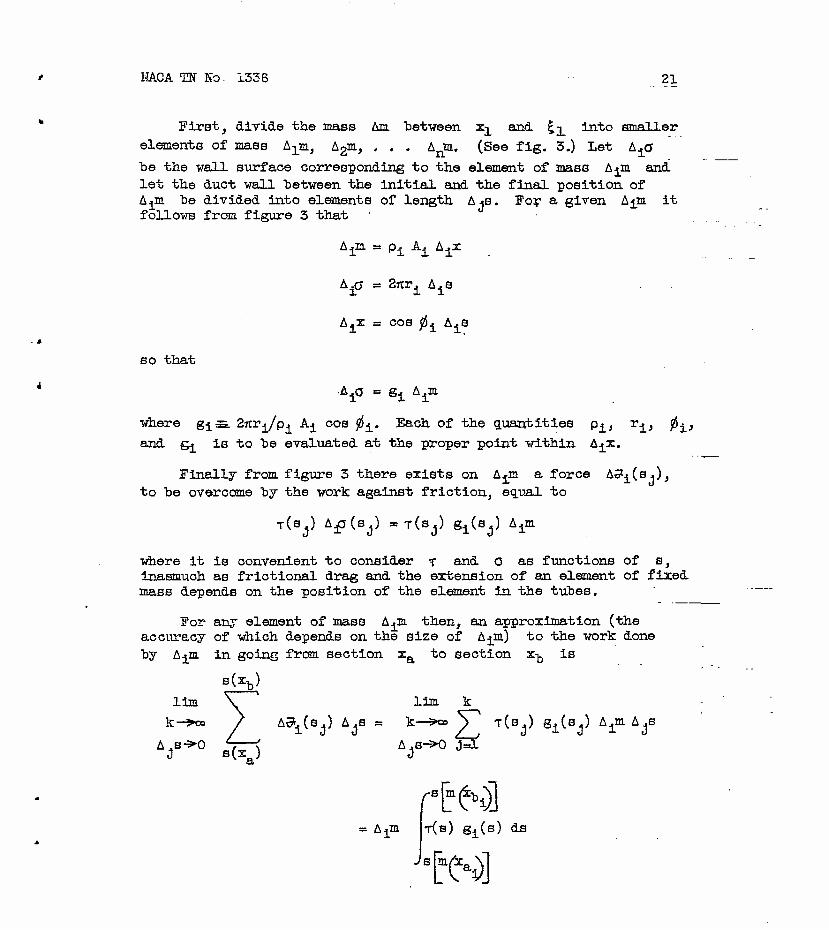
First} divide the mass Am between x± and £-j_ Into smaller
elements of mass A^m, A2m, . . . Anm. (See fig. 3.) Let A±a
be the wall surface corresponding to the element of mass A^m and let the duct wall "between the initial and the final position of Ajia he divided into elements of length A^s. For a given Aim it follows from figure 3 that
A±n = p± A± A±x
A.<y = 2nr. A.s i i i
Aji = cos fij_ A^s
so that
•A±a = g± A±m
where g±s. Zitr^/ß. A^_ cos 0^. Each of the quantities p^_, r^} fi^}
and g^ is to he evaluated at the proper point within AjX.
Finally from figure 3 there exists on A^m a force AS^CsO, to he overcome by the work against friction, equal to
T(SJ) A^J(S^) =T(SJ) gi(Sj) A±m
where it is convenient to consider T and o as functions of s, inasmuch as frictional drag and the extension of an element of fixed mass depends on the position of the element in the tubes.
For any element of mass A^m then, an approximation (the accuracy of which depends on the size of A^m) to the work done by A^m in going from section xa to section x-^ is
s(xb)
11m V lim k
k-»w y A^±(s,) AjS = k—9» ^> T(S ) SiCSj) A±m AjB
A^s-^-O 4—\ A,s-3K) j3? 3 s(x ) «3 a
= A^m T(S) g^(s) ds
Js [ts>]

NACA TN No. 1336
It follows that the corresponding, approximation to the vork done by the entire mass Am is
Bl ' * n
1=1
T(B) gi(s) ds
-/s[m(xai)]
Wim
and, as- the approximation "becomes more and more accurate as the largest Aim becomes smaller and smaller, the expression for the work, done against friction when the entire mass between x^ and £-j_
is transported to the position between x2 and £2 becomes
s[mK3 T(B) B±(B) ds
[m(^i3
mill) f^(^)l )f Aim = I J T(S) g(s) ds dm
m(xi) ^s[m(xa}]
The limit--of the double sum may be: written as an iterated Integral as follows:
*(!]_) / s[m(xb)]
fmUi) Js[m(xa)] Tg ds dm (54)
It is clear that the work done against friction when the entire mass is moved as previously described is equal also to
lim
A^m—->0
AjF—SO ?? A jF A jia = m«!) p[m(xb)]
'm(xi) ^F[m(xa}] /m(Xl) ^F[m(xa)]
(55)
'dF de
whence it follows, since the intervals for both integrations are arbitrary, that
dF ds
Tg . (56)
KACA TN No. 133 fi 25
and
a* - J 2*r \ IM ,_, / 2«r \ / da\ ^=rlpAaos gi/l^rj
then
(Tda) COB # = cos2 4 PA dF (57)
Because, fpr the small angles usually under consideration, cos2 0
is very nearly unity (for a half angle of 6°, cos2 $ = 0,989), the retention of this factor except for particularly precise work would not seem justifiable. Hence equation (53) may he written
E dx = -pA dF + p.dA (58)
The differential equation of motion is finally
-dp = pVdY + pdF . . (59)
The connection between dF and the differential loss in stagnation pressure (-dp^) can, with the help of equations (14)
and (15), be expressed in the form
"dPt dF yNde
Pt ET [2 + (7-l)lfl (BO)
Thus except for the limiting case of incompressible flew^ (-dp^)
and dF cannot be used interchangeably in defining the friction factor even for the adiabatic case where de = Q.

24 NACA TN No. 1336
APPENDIX B
THE Z LANGUAGE
In the place of N = v /7RT the equations may be formulated in terms of Z, defined through
Z = (V2/2cp)/(T +^/2c ) • («D
The numerator is the so-called dynamic temperature, the denominator is the total temperature. Z and N are related "by
Z = [(r-l)N]/[2f(7-l)N]
N = 2Z/(7-l) (1-Z)
(62)
(63)
This replacement represents a one-to-one transformation of N into Z in the range 0 to infinity for N, 0 to 1 for Z.
In order to illustrate the form that some of the earlier equa- tions take under this transformation, equations (14), (15), and (16) are written in terms of Z,
dZ
"z~ Tl-Z
i-/Z£r\zl 2 1 + i~:Uz de + (l-Z) du + (1-Z) dat (64)
j
dp
T -rv , y /- — zde- \ 7-1
i+z d)j.
7-1 Z dal
^—l)Z
(65)
dT
T /7+A
/1-Z yZ\
} 2 7-I' d© - Z du - Z da (66)

NACA TN No. 1336 25
REFERENCES
1. (a) Munk, Max M*: Pressure. Vol. I of Aerodynamic Theory, div. C, ch. II, sec, 1, W. F. Durand, ed., Julius Springer (Berlin), 1935, p. 237.
(b) Prandtl, L.: Stokes1 Theorem for Stresses, Vol. Ill of Aerodynamic Theory, div. G, sec. 6, pp. 47-49.
(c) Taylor, G. I., and Maccoll, J. W.: Conditions Within a Shock Wave. Vol. HI of Aerodynamic Theory, div. H, ch. I, sec. 6, pp. 218-222.
2. Eckart, Carl: The Thermodynamics of Irreversible Processes. I. The Simple Fluid. Phys. Rev., vol. 58, no. 3, 2d eer., Aug. 1, 1940, pp. 267-269.
3. Busemann, A.: Gas Dynamics. Part I. Theory and Concepts. R.T.P. Trans. No, 2207, Ministry of Aircraft Prod. (British). (From Handbuch dei* Experimentalphysik (Wien - Barms), Bd. 4, Teil I, 1931, pp. 343-369.)
4. Tazsonyi, Andrew: On Rotational Gas Flows, Quarterly Appl. Math., vol. Ill, no. 1, April 1945, pp. 29-37-
5. Sorg, K. W.: Supersonic Flow in Turbines and Compressors. R.A.S. Jour., vol. XLvT, no. 375, March 1942, pp. 64-85. (From Forschung., vol. 10, no. 6, Nov.-Dec. 1939, pp. 270-285.)
6. Gukhman, A. A.: On the Theory of Limiting Conditions in a Moving Gas. Jour. Tech. Phys. (C.S.S.R.), vol. 9, no. 5, 1939, pp. 411-423.
7. Bailey, Neil P.: The Thermodynamics of Air at High Velocities. Jour. Aero. Sei., vol. 11, no. 3, July 1944, pp. 227-238.
8. Nielsen, Jack N.: Compressibility Effects on Heat Transfer and i * a Pressure Drop in Smooth Cylindrical Tubes. NACA ARR No. L4C16, v^t i^ 1944. \,'
9. Binder, R. C: Limiting Isothermal Flow in Pipes. A.S.M.E. Trans., vol. 66, April 1944, pp. 221-223.
10. Keenan, Joseph H., and Neumann, Ernest P.: Friction in Pipes at Supersonic and Subsonic Velocities. NACA TN No. 963, 1945.

26 NACA TN No. 1336
11. Szczeniowski, B.: Plow of Gas through a Tube of Constant Cross- Section vith Heat Exchange through the Tube Walls. Canadian Jour. Res., vol. 23, sec. A, no. 1, Jan. 1945, pp. 1-11.
12. Hicks, Bruce L.: " Addition of Heat to a Compressible Fluid in Motion. NACA ACE Mo. E5A29, 1945.
13. Epstein, Paul S.: Testbook of Thermodynamics, John Wiley & Sons, Inc.,. 1937.
14. Bieberhach, Ludwig: Theorie der Dlfferentialgleiohugen. Pt. I, ch. II, sec. 3, Julius Springer (Berlin), 3d ed., 1930, pp. 34-35.
15. McAdams, William H.: Heat Transmission. McGraw-Hill Book Co., Inc., 2d ed., 1942.
11 11
16. Lorenz, H.: Die stationäre Strömung von Gasen durch Rohre mit veränderlichem Querschnitt. Phys. Zeitschr., Jahrg. 4, Nr. 12, März 15, 1903, pp. 333-337.
17« Prandtl, and Proeil, R.: Beiträge zur Theorie der DampfStrömung durch Düsen. TOI Zeitschr., Bd. 48, Nr. 10, März 5, 1904, pp. 348-350.
18. Stodola, A.: Steam and Gas Turhines. Vol. I. McGraw-Hill Book Co., Ine, 1927, pp. 98-101.
19. Craig, Homer Vincent: Vector and Tensor Analysis. McGraw-Hill Book Co., Inc., 1943, pp. 355-356.

I TITLE: The One-Dimensional Theory of Steady Compressible Fluid Flow in Ducts with
Friction and Heat Addition AUTHOR(S): Hicks, Bruce L.; MontgomeryJ D. and others ORIGIN, .TINS GENCV: National AdvUnrv CnmmittPP for AprpnaiiHrs, Washing• n r
ßTO- Rma
OOIO. AOtNCr NO.
TN-1336
July'47 DOC ClAll
llni-lagc
COUNTOT
II.S
PAOa iiunr Anora -2B I rilag-rg
ABSTRACT:
Steady, adiabatic, frlctional, variable-area flow of a compresstble fluid Is treated In differential form on the basis of one-dtmenslonal approximation. Basic equations are ftrst stated in terms of pressure, density, temperature, and veloctty of the fluid. Simplification and unification are then achieved by choosing the square of the local Mach number as one of the variables to descrtbe the flow. The direction of change of the flow variables can be obtatned directly from the transformed equations without Integration, as shown by two examples.
DISTRIBUTION: Request copies of this report only from Originating Ajencv DIVISION: Aerodynamics (2) SECTION: internal Flow (4) ATI SHEET NO.:R.a.4.26
SUBJECT HEADINGS: Flow through ducts (41200); Flow, One-dimensional compressible (406CC)
I- Air Matoriol Command
U.S. Air Forca AIQ TECHNICAL INDEX Wfi"ht-. oMor»on Air force Ba*a
Dayton, Ohi»

Previously catalogcd.under No: Translation No:
Subject Division:
Aerodynamics Section: