TOaxial compressor exit to the centrifugal compressor inlet. The axial compressor has the following...
38
UNCLASSIFIED AD NUMBER CLASSIFICATION CHANGES TO: FROM: LIMITATION CHANGES TO: FROM: AUTHORITY THIS PAGE IS UNCLASSIFIED AD506812 UNCLASSIFIED CONFIDENTIAL Approved for public release; distribution is unlimited. Distribution authorized to DoD only; Administrative/Operational Use; DEC 1969. Other requests shall be referred to U.S. Army Aviation Materiel Laboratories, Fort Eustis, VA 23604. USAAMRDL Notice dtd 21 May 1973; USAAMRDL Notice dtd 21 May 1973
Transcript of TOaxial compressor exit to the centrifugal compressor inlet. The axial compressor has the following...

UNCLASSIFIED
AD NUMBER
CLASSIFICATION CHANGESTO:FROM:
LIMITATION CHANGESTO:
FROM:
AUTHORITY
THIS PAGE IS UNCLASSIFIED
AD506812
UNCLASSIFIED
CONFIDENTIAL
Approved for public release; distribution isunlimited.
Distribution authorized to DoD only;Administrative/Operational Use; DEC 1969. Otherrequests shall be referred to U.S. ArmyAviation Materiel Laboratories, Fort Eustis, VA23604.
USAAMRDL Notice dtd 21 May 1973; USAAMRDLNotice dtd 21 May 1973
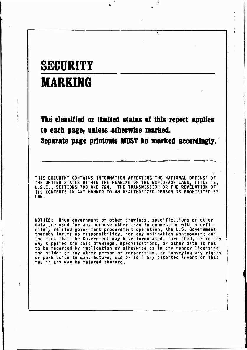
SECURITY MARKING
The classified or limited status of this report applies to each pager unless -otherwise marked. Separate page printouts MUST be marked accordingly.
THIS DOCUMENT CONTAINS INFORMATION AFFECTING THE NATIONAL DEFENSE OF THE UNITED STATES WITHIN THE MEANING OF THE ESPIONAGE LAWS, TITLE 18, U.S.C., SECTIONS 793 AND 794. THE TRANSMISSIOf OR THE REVELATION OF ITS CONTENTS IN ANY MANNER TO AN UNAUTHORIZED PERSON IS PROHIBITED BY LAW.
NOTICE: When government or data are used for any purpos nitely related government pr thereby incurs no responsibi the fact that the Government way supplied the said drawin to be regarded by implicatio the holder or any other pers or permission to manufacture may in any way be related th
other drawings, specifications or other e other than in connection with a defi- ocurement operation, the U.S. Government lity, nor any obligation whatsoever; and may have formulated, furnished, or in any
gs, specifications, or other data is not n or otherwise as in any manner licensing on or corporation, or conveying any rights , use or sell any patented invention that ereto.

-J
GO CD ©
Q ^■3
CONFIDENTIAL u
USAAVLABS TECHNICAL REPORT 69-10A
ADVANCEMENT OF SMALL GAS TORDINE COMPONENT TECHNOLOGY,
ADVANCED SMALL AXIAL COMPRESSOR (U)
VOLUME I - ADDENDUM ANALYSIS AND DESIGN
James V. Davis
December 1969
U. S. ARMY AVIATION MATERIEL LABORATORIES FORT EUSTIS, VIRGINIA
CONTRACT DA 44-T77-AMC-296(T)
CONTINENTAL AVIATION AND ENGINEERING CORPORATION
DETROIT, MICHIGAN
\tt Mltlttum l*i -.• . unty t-Kj-nr. i It.is dm ttllMTJ .1 'I -mi I I.-' im ' Piit-ini.- UK- Poi.arlm.-nl -.1 !).■;.-
.i.j.M- >v*\ .,: US AI-II.V Aviati n. i .rt I ubtis. V'irait.i.i .: U>'>1
l.aburi'i.ri.
|" GBOUP 4 j Downgraded at 3 year inlvrvatt. I d«claiiiFi«d after 12 ytari
i .,[ U.fens.' .»i I tit- llnii-d St.u. . willun i'i.- ii.u . ' thf I-■-inuiMi;- [,aw i ill" [* USX - Hi-» 7*H And 7*H. It- lr,n , ,i..n ur the jtn-n ill il-. i tmtei I -. ir. my •:I.UIIHT I., -in
CONFIDENTIAL c°py*^-44_coPies

~4
DISCLAIMERS
The findings in this report are not to be construed as an official Depart- ment of the Army position unless so designated by other authorized documents.
When Government drawings, specifications, or other data are used for any purpose other than in connection with a definitely related Government procurement operation, the United States Government thereby incurs no responsibility nor any obligation whatsoever; and the fact that the Govern- ment may have formulated, furnished, or in any way supplied the said drawings, specifications, or other data is not to be regarded by impli- cation or otherwise as in any manner licensing the holder or any other person or corporation, or conveying any rights or permission, to manu- facture, use, or sell any patented invention that may in any way be related thereto.
DISPOSITION INSTRUCTIONS
When this report is no longer needed, Department of the Army organi- zations will destroy it in accordance with the procedures given in AR 380-5.

CONFIDENTIAL
DEPARTMENT OF THE ARM* U. S ARMY AVIATION MATERIEL LABORATORIES
FORT EUSTIS. VIRGINIA 23604
(U) The research described herein, which was conducted by Continental Aviation and Engineering Corporation, was performed under U. S. Army Contract DA Mt-177-AMC-296(T) The work was performed under the technical management of Mr. David B. Cale, Propulsion Division, U.S. Army Aviation Materiel Laboratories.
(U) Appropriate technical personnel of this Command have reviewed this report and concur with the conclusions contained herein.
(U) The findings and recommendations outlined herein were considered in planning the subsequent phases of the program.
(U) This document is the classified addendum to USAAVLABS Technical Report 69-lOA.
CONFIDENTIAL Page ' °f 35 Pas"

CONFIDENTIAL Task 1G16ZZ03D14413
Contract DA 44- 177-AMC-Z96(T) USAAVLABS Technical Report 69-10A
December 1969
ADVANCEMENT OF SMALL GAS TURBINE COMPONENT TECHNOLOGY,
ADVANCED SMALL AXIAL COMPRESSOR (U)
VOLUME I - ADDENDUM ANALYSIS AND DESIGN
Continental Report No. 1033
By
James V. Davis
GROUP - 4 Downgraded at 3 ytar inttrvalt;
d«clattifi«d aft«r 12 y«ari.
Trtii document conto mt information off «cling Hie Nelionol Dfftntt of th« United Stitt* within ffi« mooning of rit# Et»io#cfe Low, Tille 18 USC, actions 793 and 794. Iti Isanuniition or the revelation of its contents in arj mountJ to an wwutno-iied perion if prohibited by law.
Prepared By-
Continental Aviation and Engineering Corporation Detroit, Michigan
for
U.S. ARMY AVIATION MATERIEL LABORATORIES FORT EUSTIS, VIRGINIA
In addition to security requirements which apply to tl.ia document and must be met, each transmittal outside the Department of Dei'enae must have prior approval of US Army Aviation Materiel Laboratunoi Fort Fuslis, Virginia ZJ604.
CONFIDENTIAL Page L of 35 Pages

n^ 1
(U) SUMMARY
A complete two-stage aerodynamic axial compressor design was prepared using the optimum axial compressor characteristics obtained from a preliminary design study of a family of advanced axial compres- sors capable of being matched with the USAAVLABS advanced centrifugal technology. Fully variable part span inlet guide vanes were designed to ensure axial-centrifugal operation capability from 50 to 100 percent of engine speed. Two transition ducts, which differed primarily in length, were designed to provide an efficient aerodynamic flow path from the axial compressor exit to the centrifugal compressor inlet.
The axial compressor has the following aerodynamic design point performance goals:
Airflow = 5 lb /sec Pressure ratio = 3.0:1 Adiabatic efficiency - 83 percent Inlet hub tip ratio = 0.494 First rotor tip speed = 1410 ft/sec
in Page 3 of 35 Pages
'

(U) FOREWORD
This report,prepared by Continental Aviation and Engineering Corporation, presents Phase I of a three-phase small axial compressor program for the advancement of small gas turbine component technology.
The program was sponsored by the United States Army Aviation Materiel Laboratories under Contract DA 44-177 -AMC-296(T), Task 1G162203 D14413.
Phase I presents a study of a family of advanced axial compres- sors. It is reported as Volume I with an addendum under a separate cover. The addendum is the analysis and design.
Phases II and III are presented in Volume II. Phase II presents the axial compressor fabrication and test. Phase III presents the axial compressor redesign, fabrication, and test.
v Page 4 of 35 Pages

F —
(U) TABLE OF CONTENTS
Page
SUMMARY iii
FOREWORD v
LIST OF ILLUSTRATIONS viii
LIST OF TABLES ix
COMPRESSOR AERODYNAMIC DESIGN 1
Design Procedure 1 Design Performance 2 Flow Path 7 Velocity Triangles 8 Blade and Vane Geometry 8 Variable Inlet Guide Vanes 15 Transition Ducts 19 Estimated Performance 19
DISTRIBUTION ^
VI1 Page 5 of 35 Pages
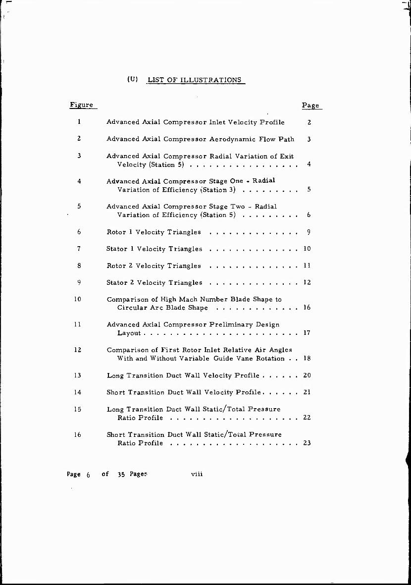
(U) LIST OF ILLUSTRATIONS
Figure Page
1 Advanced Axial Compressor Inlet Velocity Profile 2
2 Advanced Axial Compressor Aerodynamic Flow Path 3
3 Advanced Axial Compressor Radial Variation of Exit Velocity (Station 5) 4
4 Advanced Axial Compressor Stage One - Radial Variation of Efficiency (Station 3) 5
5 Advanced Axial Compressor Stage Two - Radial Variation of Efficiency (Station 5) 6
6 Rotor 1 Velocity Triangles 9
7 Stator 1 Velocity Triangles 10
8 Rotor 2 Velocity Triangles 11
9 Stator 2 Velocity Triangles 12
10 Comparison of High Mach Number Blade Shape to Circular Arc Blade Shape 16
11 Advanced Axial Compressor Preliminary Design Layout 17
12 Comparison of First Rotor Inlet Relative Air Angles With and Without Variable Guide Vane Rotation . . 18
13 Long Transition Duct Wall Velocity Profile 20
14 Short Transition Duct Wall Velocity Profile 21
15 Long Transition Duct Wall Static/Total Pressure Ratio Profile 22
16 Short Transition Duct Wall Static/Total Pressure Ratio Profile 23
Page 6 °f 35 Pager viii
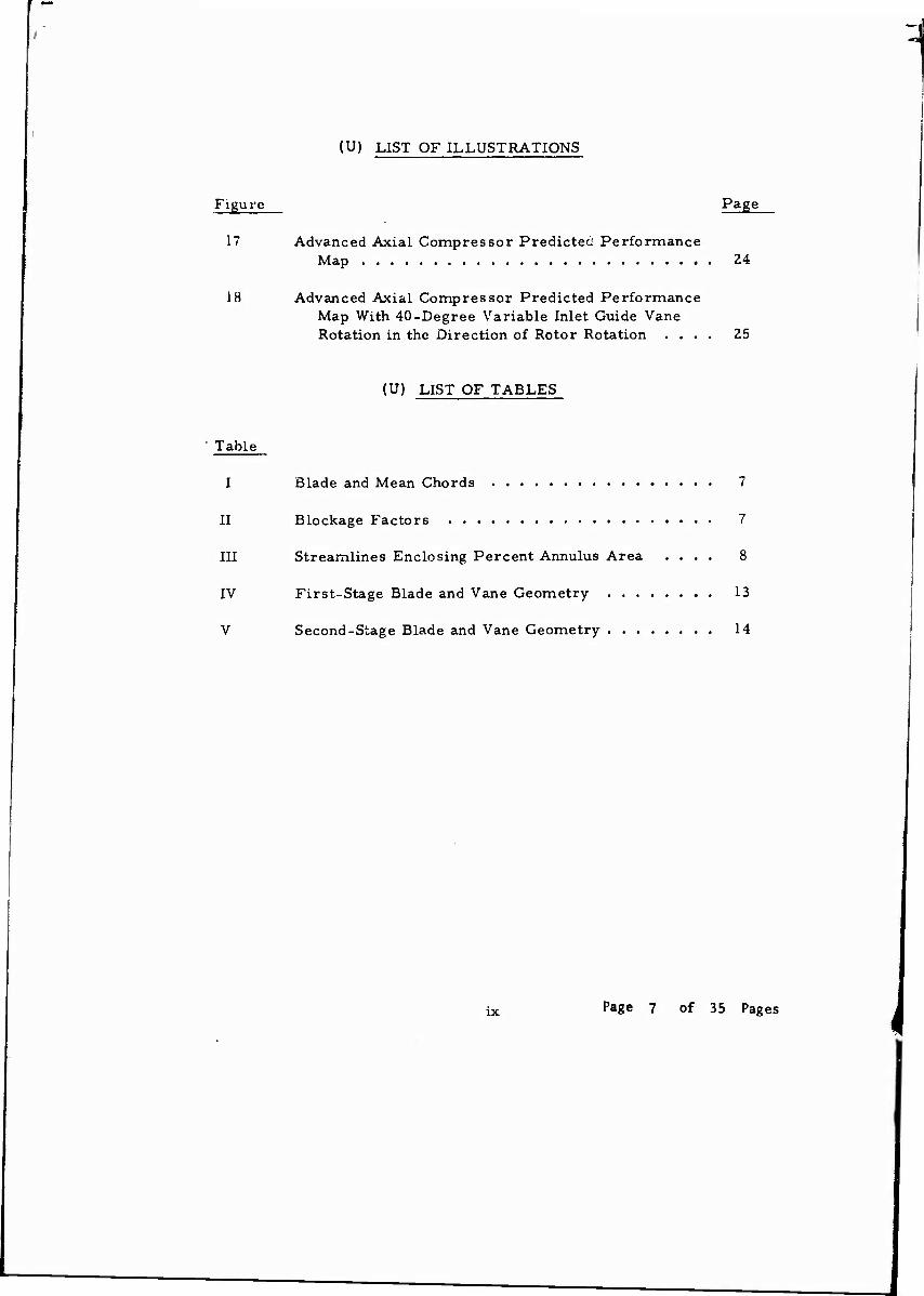
(U) LIST OF ILLUSTRATIONS
Figure
17
18
Page
Advanced Axial Compressor Predicted Performance Map
Advanced Axial Compressor Predicted Performance Map With 40-Degree Variable Inlet Guide Vane Rotation in the Direction of Rotor Rotation . . .
24
25
(U) LIST OF TABLES
Table
I
II
III
IV
V
Blade and Mean Chords 7
Blockage Factors 7
Streamlines Enclosing Percent Annulus Area .... 8
First-Stage Blade and Vane Geometry 13
Second-Stage Blade and Vane Geometry 14
IX Page 7 of 35 Pages
CONFIDENTIAL (C) COMPRESSOR AERODYNAMIC DESIGN (U)
(C) DESIGN PROCEDURE (U)
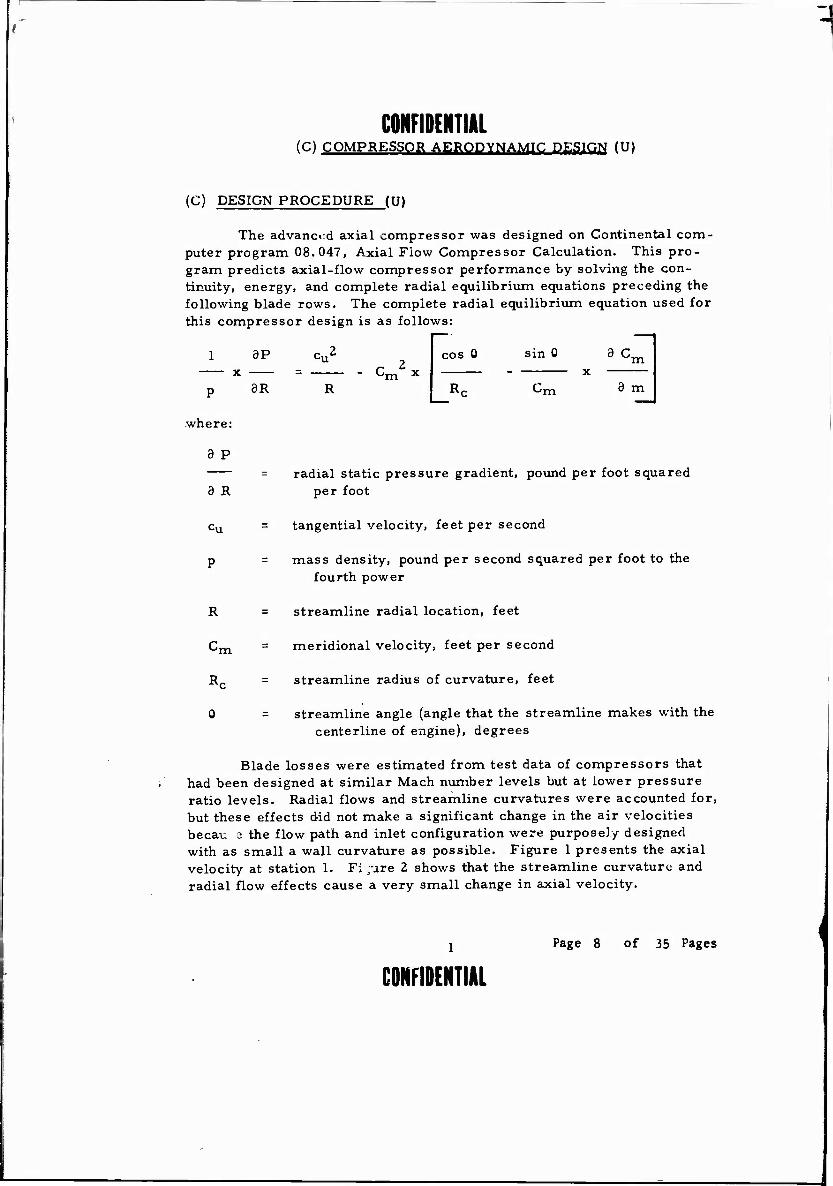
The advanced axial compressor was designed on Continental com- puter program 08.047, Axial Flow Compressor Calculation. This pro- gram predicts axial-flow compressor performance by solving the con- tinuity, energy, and complete radial equilibrium equations preceding the following blade rows. The complete radial equilibrium equation used for this compressor design is as follows:
P
where:
9 P
1 3P cu2
3R R x — -. - Cm
2 x cos 0 sin 0 9 Cm
Rc Cm 9 m
= radial static pressure gradient, pound per foot squared 3 R per foot
-u = tangential velocity, feet per second
p = mass density, pound per second squared per foot to the fourth power
R = streamline radial location, feet
Cm = meridional velocity, feet per second
Rc = streamline radius of curvature, feet
0 = streamline angle (angle that the streamline makes with the centerline of engine), degrees
Blade losses were estimated from test data of compressors that had been designed at similar Mach number levels but at lower pressure ratio levels. Radial flows and streamline curvatures were accounted for, but these effects did not make a significant change in the air velocities becau 3 the flow path and inlet configuration were purposely designed with as small a wall curvature as possible. Figure 1 presents the axial velocity at station 1. F; /ire 2 shows that the streamline curvature and radial flow effects cause a very small change in axial velocity.
Y Page 8 of 35 Pages
CONFIDENTIAL

CONFIDENTIAL 680
H
8660 j w >
<
H W 3 z
620
600
Three-Dimensional Solution (Streamline Curvature and Radial Flow Effects)
V- ^
Two-Dimensional Solution
0.5 0.6 0.7 0.8 0.9 1.0
RADIUS RATIO - R/RTIp
Figure 1. (C) Advanced Axial Compressor Inlet Velocity Profile. (U)
(C) DESIGN PERFORMANCE (U)
(U) The design performance of the axial compressor quoted at the end of the transition duct is .listed below. A 1-percent transition duct total pressure loss was assumed.
Overall pressure ratio Overall efficiency First-Stage pressure ratio Second-Stage pressxire ratio First-Stage efficiency Second-Stage efficiency First rotor tip speed
3.0:1 82.3 percent 1.825:1 1.660:1 85.5 percent 82.9 percent 1415 feet per second
(The slight increase in tip speed over that of the cursory design reflects an additional optimization of tip speed with rotor diffusion. )
Paae 9 of 35 Pages
CONFIDENTIAL

CONFIDENTIAL
1.34" Radius
Station
1.735"
2.09" 1.92"
2.175"
2 3
-Lit—L 5 I
Airflow = 5 Lb/Sec Pressure Ratio = 3. 0:1 Efficiency = 82. 3 Percent Airflow/Annulus Area = 40. 96 Lb/Sec/Ft* Airflow/Frontal Area = 30. 98 Lb/Sec /Ft4
Inlet Hub/Tip Ratio = 0. 494
"igure 2. (C) Advanced Axial Compressor Aerodynamic Flow Path. (U)
Page 10 of 35 Pages
CONFIDENTIAL

CONFIDENTIAL (C) The pressure ratio split between the two stages balances the rote diffusion. Because of the increase in temperature after the first st . the second-stage pressure ratio must be reduced to prevent ex- c ioive rotor diffusion.
(C) A constant radial pressure ratio distribution was used to main- tain a low radial gradient of axial velocity throughout the axial compres- sor and into the centrifugal compressor inducer. A representative axial velocity gradient is shown in Figure 3. A low axial velocity gradient tends to spread the compressor work over the entire blade span rather than to concentrate the work in one area. Thus, the stage matching problems are minimized.
(U) The radial gradient of efficiency shown in Figures 4 and 5 reflects the relatively high shock losses at the tip region of the rotors. These losses have been minimized, however, by using a high Mach number rotor blade section that efficiently converts the kinetic energy of the air stream to static pressure.
H 630 U o u >
S 620
X <
X w as 610 O to « W
0,
o u
600 0.80 0.85 0.90 0.95
RADIUS RATIO - R/RTIp
1.0
Figure 3. (C) Advanced Axial Compressor Radial Variation of Exit Velocity (Station 5). (U)
Page 11 of "5 Pages 4
CONFIDENTIAL

CONFIDENTIAL
7 T ~[_
7 ~Xt
[V I
o 00 00 00 00 00 00
ADM3IDLJJ3 DIIV9VKIV 3NO 3DVXS
y c 0
W in 0 O*
c d 0 •H
It
H-l
•iH
H os
a) >
o _| o> OS •rH
o i ■a a]
0 OS M H i
< 1)
in 00
OS C 0
O t-i V 00
a (fl < w OS M
0 to
o tn ao 0) • u O
£ 0 U
in d D
O*
"0 ro
0 c c .2 era _j_t
<! S
u
Page 12 of 35 Pages
CONFIDENTIAL

CONFIDENTIAL
o e V
W
o 0>
00 00 00 00
rg 00
o 00
c 0
■iH •!-> in
hi
d >
0, ifl i—1 •r-i
H ■v
o PS PS
<y öS 0 o 1 *
0 H
in V H 00
< n)
PS W in 00 W i*
Ö 0 © i-i en
Q to
< 4) (-1
PS
0 o U 00
d
ed A
xia
l 5).
(
U)
ID ° a a .2 (4 +J
O
Ad
v
(Sta
ADN3IDI333 DIXV9VIQV OAVX 3DVIS u
Page 13 of 35 Pages
CONFIDENTIAL
in 0) u 60

CONFIDENTIAL (C) FLOW PATH (U)
(U) The axial compressor flow path is shown in Figure 2. This flow path embodies aspect ratio (blade height divided by the mean radius chord length) and ramp angle optimizations. In addition, aerodynamic blockage factors (flow area divided by the actual or physical area) have been included.
(C) Continental's axial compressor experience has shown that exces- sively low aspect blading produces high losses, and that excessively high aspect ratio blading limits flow range. The axial compressor aspect ratios, which have been optimized for efficiency and flow range, and the number of blades and the mean chords are listed in Table I.
(C) TABLE I (U) ■ BLADE AND MEAN CHORDS (U)
Blade Aspect Row Ratio Mean Chord Number of Blades
1.83 in. 15 0.55 in. 47 0.75 in. 41 0.57 in. 53
(C) Blockage factors, which account for the wall boundary layers, follow in Table II. These values were obtained from test data on similar, but lower pressure ratio level, transonic axial compressors. The axial station locations are indicated in Figure 2.
(C) TABLE II (U) BLOCKAGE FACTORS (U)
Axial Station Blockage Factor
1 0.99 2 0.98 3 0.97 4 0.97 5 0.97
Rotor 1 0.646 Stator 1 1.623 Rotor 2 0.953 Stator 2 1.031
7 Page 14 of 35 Pages
CONFIDENTIAL

(U) It should be noted that the optimum axial compressor is about 0.47 inch longer than that of the cursory design. This is because the cursory design aspect ratios were assumed to be 1. 0 .
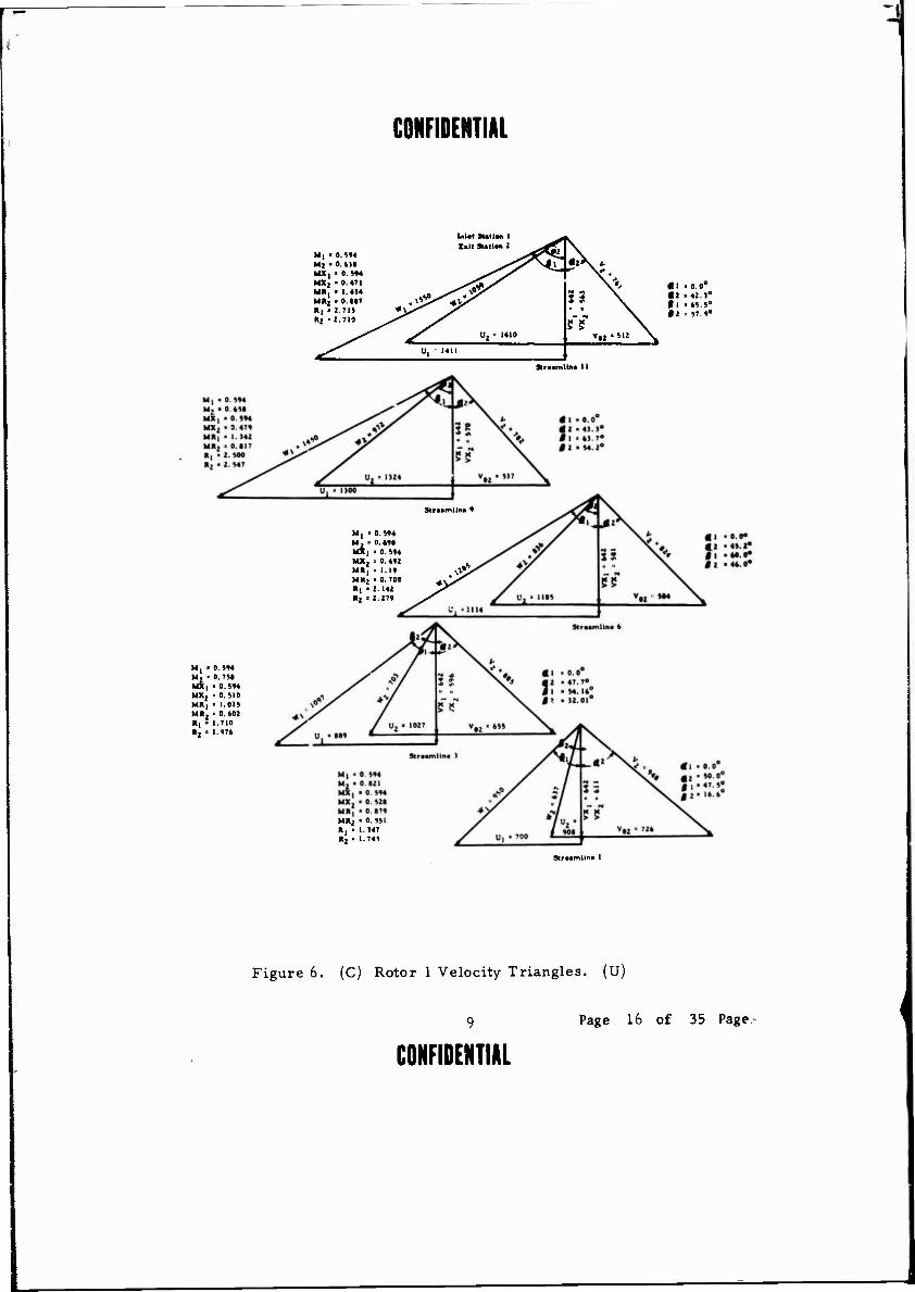
(C) VELOCITY TRIANGLES (U)
(U) The velocity triangles, which completely define the aerodynamics of the compressor, are shown in Figures 6 through 9.
(U) Each figure presents the inlet and exit velocity triangles for the respective blade row. In addition, Mach numbers, air angles, and radii are listed. Five velocity triangles are shown for each blade row. These triangles are located at selected streamlines that enclose the percent an- nulus area as shown in Table III.
(U) TABLE in STREAMLINES ENCLOSING PERCENT ANNULUS AREA
Streamline Percent Annulus Area
11 100 9 80 6 50 3 20 1 0
Thus, for example, streamline 11 is at the aerodynamic blade tip, streamline 6 is located at the mean area location, and streamline 1 is at the aerodynamic blade hub.
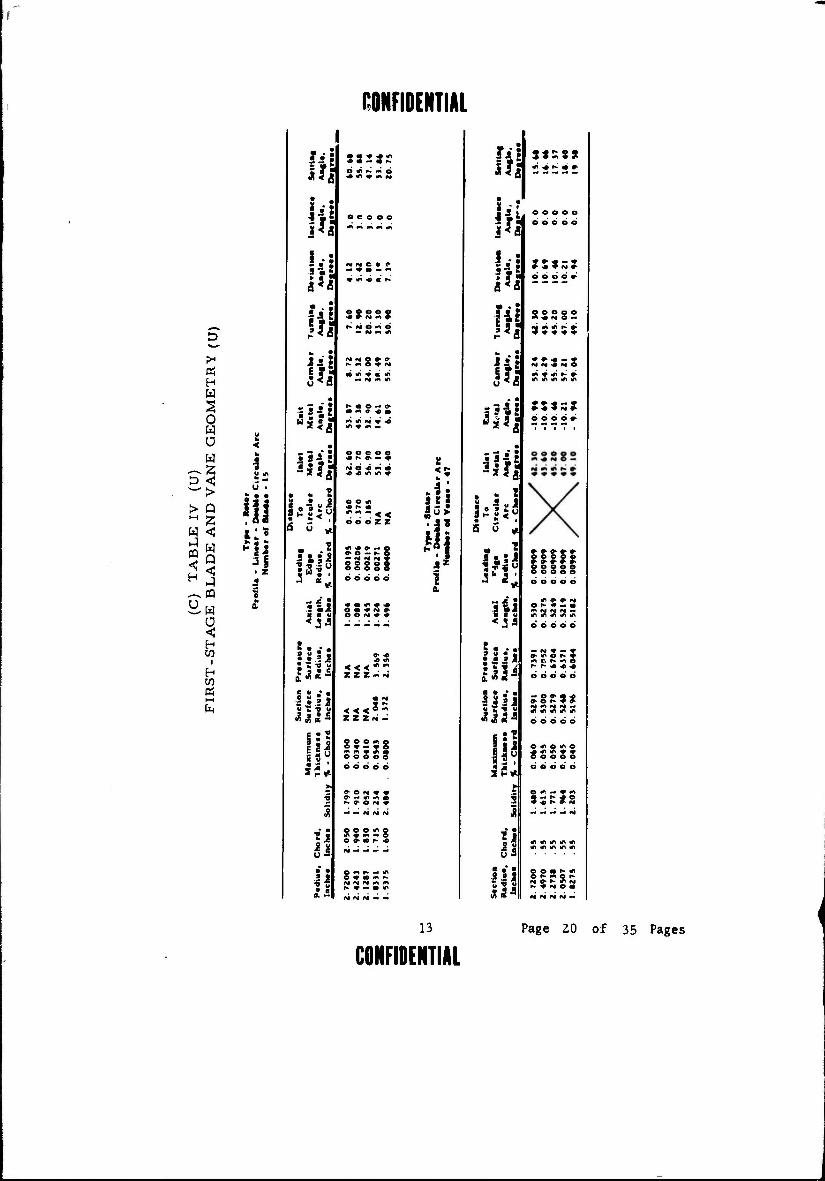
(U) BLADE AND VANE GEOMETRY
The blade and vane geometry parameters listed in Tables IV and V completely define the geometric profiles of each blade row.
Circular arc vane profiles were selected for the stators because of their relatively high subsonic Mach number and air turning angle re- quirements. Circular arc blade profiles were also selected for the second rotor because the relative Mach numbers entering this blade row are low enough to allow the use of this profile and still maintain high efficiencies.
Page 15 of 35 Pages 8
r — -j
CONFIDENTIAL
litlat Suit an 1 E»ll Sutton 2
M, ■ 0. 544 Ml ■ 0. 41» V^| •iX v *. MX | ■ 0. 544 V* MXj ■ 0 471 MR. ■ 1.414 ^^ V MR] ■ 0. M7 «fr 3 i »1 • 1.711 t> Zs M a
Rj ■ 2.710
Uj. 1410 55
VH • 511 \
"l 1411
«1 -0.0° «2 -42 1° I 1 ■ .5. 4° $1 -- 57.4°
■kraamlin« 11
9tr*amllnt 4
M, ■ 0.544 M , < 0. /><>§ MX, ■ 0.544 MX2 ■ 0.442 MR, > 1. 14 S*> MK2 « 0. 70« R| > 2. 142
+\r
Rj > 2.274
M , ■ 0. 544 M, > 0.75» MX | > 0. 544 MXj = 0.510 MR, ■ 1.015 MR, ' 0. «02 R, • 1.710 R, = 1.476
MR2 ■ 0. 55 R, ■ 1.147 R2 " 1.745
Strtamlln« 1
Figure 6. (C) Rotor 1 Velocity Triangles. (U)
Page 16 of 35 Page
CONFIDENTIAL

"1
CONFIDENTIAL
Intel Station i Emit Station )
M2 • 0.6)8 M. ■ 0. Ml M*2 . 0.471 MX, « 0. 5)) R2 = 2.710 Rj » 2.70«
M2 ' 0. 653 Mj = 0. 5)3 MX2 » 0.47) MX) ' 0.555 R2 = 2. 547 R, = 2.572
Streamline 9
M2 = 0.758 M) « 0. 53) MXj - 0.510 MX, = 0. 535 R! = 1.976 R, - 2.110
«2- 42.5° A 3 = 0. 0°
«12= 43.3° a )= o.o°
Mj = 0. 535 MX2 = 0.492 MX, " 0.53)
R) 279 352 «* = 45.2°
0 5 = 0.0°
«2= 47.7 «)= 0.0°
M2 ■ 0.821 Mj = 0. 5)3 MX2 = 0. 528 MXj = 0. 5)) Rl = 1.745
83 Streamline 6
Streamline 1
Figure 7. (C) Stator 1 Velocity Triangles. (U)
Page 17 of 35 Pages 10
CONFIDENTIAL 1

-I
Ü8KFI0ENTIAL
Inlot Station 3
M, .«.SI! Exit Station 4
M; • 0. »»0 MX| • 0. »13 ^s3c*i* &K MX] » 0.436 MR, > 1.2(3 MRt • 0. SOT Ri • 2. 70» Rj • I. HI «N
r Oj . 1410
IS ■ »
55 vM.»j. \
U, • I40t
• I >o.o"
ii ■*>♦; tl' »7,3
V Straamlln« 11
Mt • 0. »11 /Kßl »o». < » 2 • 0. «02 V ( MX, ■ 0 »11
SS*?I \> MX2 » ',.440 MR, > 1.211 .*£" s<+/
X MRj • 0.764 R, • 2. »71 Rz • 2. otIO
<y^ *"x M It
55 °2' 1352 V«2 ' "7 X
».■ 111«
tl'0.0° 12* 41.1s
|l"«4.1° »2 ■ M. »°
Stroamlino 9
M{ >0.«2S MX, « 0. »11 MXj • 0.447
Straamlln« 3 M, * 0. »11 MI* 0.477 MX, • 0. »11 MX MR,
• 0. 462 ' 0. W4
MR, = 0. »«4
*1' l.*12
*2' J.0W
St r «am Hi» 1
Figure 8. (C) Rotor 2 Velocity Triangles. (U)
11 Page 18 of 35 Pages
CONFIDENTIAL

-J
CONFIDENTIAL
SlMor 2 Valeclty TriM|l*4
Inl.t St.tlo« 4 E«it SUtl» 5
"1
»2-
0.S90 0.449 > 0.4)4 ■ 0.4*9 2.710 2.712
Mj • 0.M1 M, > 0.470 MX, • 0.440 MX, • 0.470 R| .2.400 R, -2. »IS
StrnunllM 9
Mj « 0.470 MX2 • 0. 447 MX, • 0.4?0 n, ■ 2.424 R, • 2.462
ti\ .0.470 MX, ■ 0.4J5 MX, .0.470 R. it. til R, .2.2«
n 1 M
1*1 •»
£2
"*» \y
X* A
v02 • 40]
v„.o WnunllM >
M| «0.477 M, • 0.471 MX; • 0.442 MX, i 0.471 R| • 2. 099 Rj «2. 10)
l|. 42.4* 1). 0.0s
Stratmltn« 11
• 2 - 41.1" 41). 0.0°
•2. 4S.0 I ) . 0.0"
*t<2 X.
n *•
V » m
V.2 ■ »44 >^
i° | v„ • 0
> 2 • 44. )" I) • 0.0°
Straamlin« 4
»2« 47.0" • 3-0.0°
Slraunlln* I
Figure 9. (C) Stator 2 Velocity Triangles. (U)
Page 19 of 35 Pages 12
CONFIDENTIAL
CONFIDENTIAL
« H W
o w Ü w
~> Q 2 < W Q <
CQ
•W Ü < H W
i
H
s • • 14 !i
• z
0
* •
l-il 7 • •
sail
3« * ■# «n • — • r-
e ** *»■' M e
NNC» f — * «e — *■*
* * •* * •*
©coo© -* *■ «M -. #
r- *t b *■« b
N w» O •> * f* <n O «# i
i» 2 H
k h .3 8
la s *
■ • • 9
Saw
t. •"in 8 ?««
I'll
s Jl i s u -
ü
o o * * r- «■
o o o 2 Z
IN N f
o e o e e
J • <n * * O • *# M »■ o e ry * *
ZZZ^N
< < <°~ 2 Z 2 M -
o o o *n © o * - • 5 ** ■* * tr ■ o © o o o öd d do
»■ — «r ( f* » O i
O O O m © »n «f **i — ©
O «■« i*- — »n © ♦ « m r~ fs* N «s* ft »n r» * — * *
fli *!
1 a
lii
? f!
Mid
S u
§ 8 s a
B • ■ .
IB I
B • •
3«S$»
e e e © o o o o © o
'-» = ' e e b ö »
e © o Q e o © ' *4 © .
M m «ft f. #.
NNSNO
©bob*
£ £ £ £ ,
o o o o o
o o o o ©
— fSi * - * <r *r» © ?- * m G r» m o r- p* * * -*
bdbeb
— ©*>•* ^ o r* # fr M « N «I —
d do do
o * o * © «f> «ft * *
o © © o deded
O M — * m
© o • r» tn o r» m o f- IM «■* r- «r Ni r* ♦ Ml o m
13
CONFIDENTIAL Page 20 of 35 Pages

CONFIDENTIAL
1
W
tq < H
U
« H W
O w Ü w
< >
< w a 5 m w ü < H w
i
0.
O Ü w
kg
Sä E "Si IM i. ■
£ ?H «3^|
« * rf» * M N N ir <Ar
a' * o * <* rf» i/t + **
O *» O *» O
•A * I
O rt r- « (T
Ha I H *> 1- — " ' 3 < £ I **»•>■
12!
1 c «I ■a
hit s « « i
H 0 u
* • J 9 «Si • ail •fl" £ w * i
.8
o o o o o
o o o o o
rsi <T .
S3:
ir ^ rt IT oo 0* N h- m o
o o o e»5 66606
00066
b yn
US
ill
8 m in « o — M m m
OS"3! N N N N N
2 ? -
*■»<
5 as^
- = •;
ji ij 1131
«a*
xs
r» © * * «y * O *» — |> ■> «
31 m X
000
Page 21 of 35 Pages 14
CONFIDENTIAL
1
The relative Mach numbers entering the first rotor, however, are high enough to cause high losses if circular arc profiles are used for this blade row. Therefore, a high Mach number section was used to provide as high a stage efficiency as possible consistent with the high pressure ratio requirement. This section limits the flow expansion on the suction surface to reduce passage shock losses. A comparison of this section with a circular arc section is shown on Figure 10.
(U) VARIABLE INLET GUIDf VANES
The variable inlet guide vanes are designed to provide sufficient flow turning to ensure adequate flow range on the combined axial-centrif- ugal unit at part power. These vanes, which are shown on Figure 11, are cantilevered from the tip and extend to 50 percent of the blade span. A chordal taper ratio is provided to match the rotor inlet relative angles spanwise.
The advantages of 50 percent span vanes over full span vanes are:
Mechanical simplicity.
Cleaner aerodynamic flow path (no hub variable inlet guide vane shaft protrusion or clearance space as the guide vanes are rotated).
Less weight.
The minor disadvantage of the part span vanes is that the first rotor design inlet air angles cannot be exactly matched spanwise. Figure 12 shows that the maximum rotor inlet air angle difference with guide vane rotation occurs at the hub and is less than 5 degrees in magnitude. This difference would be less with full span vanes. However, no incidence angle problems will exist at the hub since the low inlet relative Mach num- bers at this station will allow incidence angle variations of this magnitude without occurrence of severe losses.
In addition, Continental's test experience has shown th; * when full span variable guide vanes are severed 50 percent from the hub no signifi- cant change in overall compressor performance is noticed.
15 Page 22 of 35 Pages ,

Inlet Flow Direction
Wave
Circular Arc Blade Shape
Expansion Wavee (Region of Increaaing Mach Number)
Inlat Flow Direction
Figure 10. (U) Comparison of High Mach Number Blade Shape to Circu- lar Arc Blade Shape.
Page J3 of 35 Pages 16

3 0 >•
-1 B so
III u
Q t» u n) C
a
a, 0 w
1)
s o u
3 « u S
>
<
v u
ac
17 Page 24 of 35 Pages

1
w J Ü z < K < H W
z w
<
W « 05 0 H 0 «
1.25 1.50 1.75 2.00 2.25
RADIUS-INCHES
2.50 2.75
Figure 12. (U) Comparison of First Rotor Inlet Relative Air Angles With and Without Variable Guide Vane Rotation.
Page 25 of 35 Pages 18
j
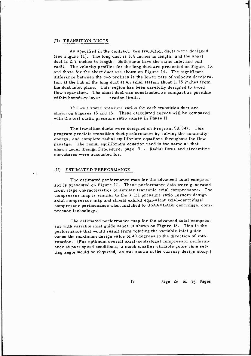
(U) TRANSITION DUCTS
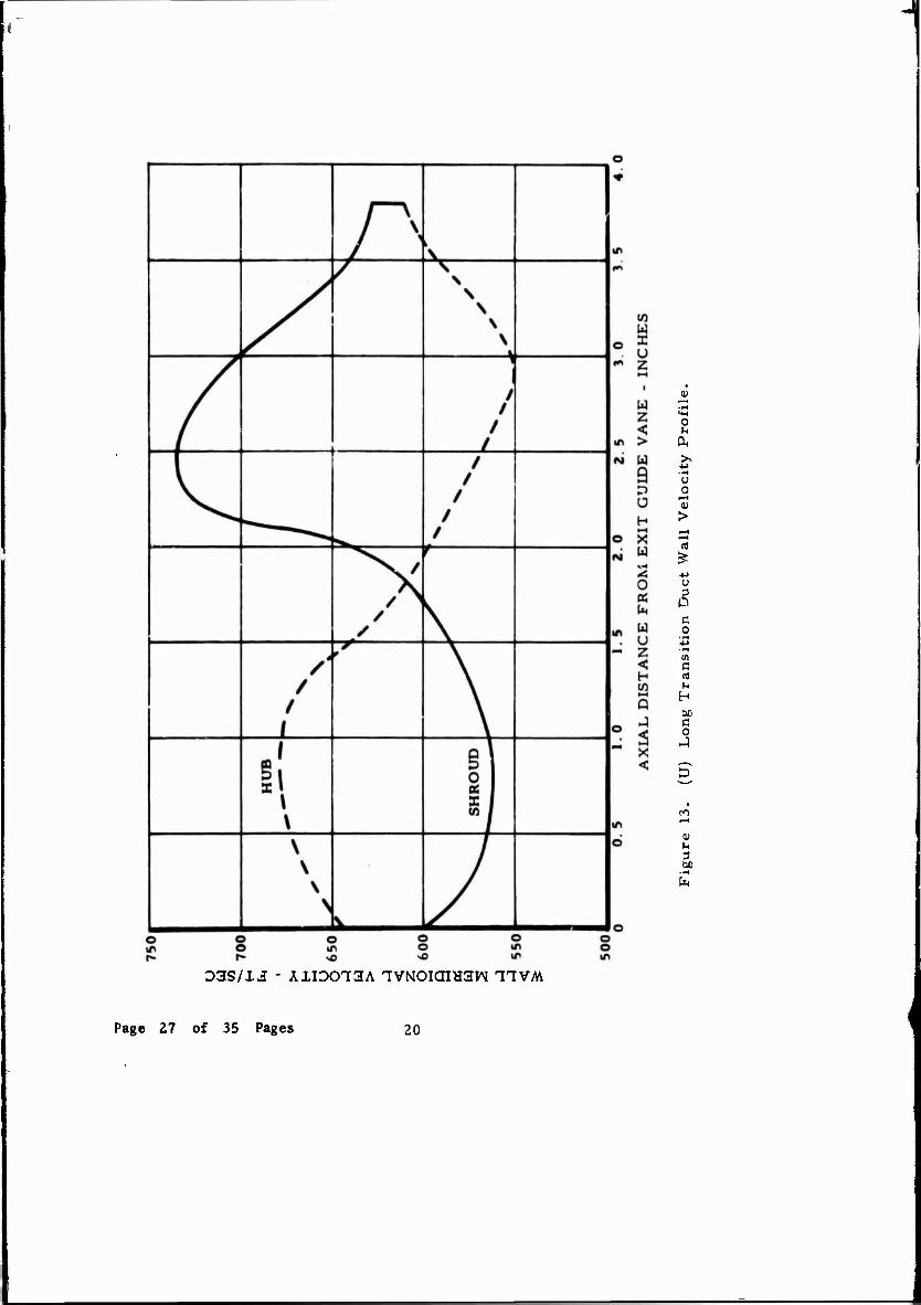
As specified in the contract, two transition ducts were designed (see Figure 11). The long duct is 3.8 inches in length, and the short duct is 2. 7 inches in length. Both ducts have the same inlet and exit radii. The velocity profiles for the long duct are presented on Figure 13, and those for the short duct are shown on Figure 14. The significant difference between the two profiles is the lower rate of velocity decelera- tion at the hub of the long duct at an axial station about 1.75 inches from the duct inlet plane. This region has been carefully designed to avoid flow separation. Tho short duct was constructed as compact as possible within boundary layer oration limits.
Thü waii static pressure ratios for each transition duct are shown on Figures 15 and 16. These calculated curves will be compared with the test static pressure ratio values in Phase II.
The transition ducts were designed on Program 08.047. This program predicts transition duct performance by solving the continuity, energy, and complete radial equilibrium equations throughout the flow passage. The radial equilibrium equation used is the same as that shown under Design Procedure, page '1 . Radial flows and streamline curvatures were accounted for.
(U) ESTIMATED PERFORMANCE
The estimated performance map for the advanced axial compres- sor is presented on Figure 17. These performance data were generated from stage characteristics of similar transonic axial compressors. The compressor map is similar to the 3. 1:1 pressure ratio cursory design axial compressor map and should exhibit equivalent axial-centrifugal compressor performance when matched to USAAVLABS centrifugal com- pressor technology.
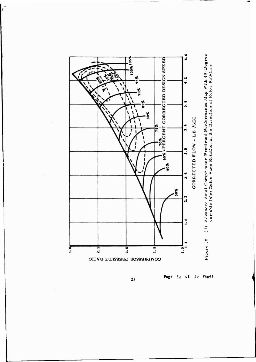
The estimated performance map for the advanced axial compres- sor with variable inlet guide vanes is shown on Figure 18. This is the performance that would result from rotating the variable inlet guide vanes the maximum design value of 40 degrees in the direction of rotOi rotation. (For optimum overall axial-centrifugal compressor perform- ance at part speed conditions, a much smaller variable guide vane set- ting angle would be required, as was shown in the cursory design study.)
19 Page 26 of 35 Pages
o u
u o
f—I 0)
>
& c o
c n)
H M
O
0)
3,
D3S/I3 - ÄIIDOT3A TVNOIOIHSW TTVM
Page 27 of 35 Pages 20

1
750
U W en
H
H >-i
Ü o A W > A < Z o
«
700
650
600
550
500 0.5 10 1.5 2.0 2.5
AXIAL DISTANCE FROM EXIT GUIDE VANE - INCHES
3.0
Figure 14. (U) Short Transition Duct Wall Velocity Profile.
21 Page 28 of 35 Pages

w
U 0 Z in i—i 0, o ■ 0
ro w • H ■w
z < > 0)
u 3
m 9 D 0)
f>j U H _, l-H
X 3 w 0
H o 2
0 ■H
N 05 in -p
W w f—(
u rt
in
2 < -p
u M tf) d
Q Q
J S
0
X to o <
u H M C 0 A
in D o
o
in ■—1
u
o o OIXVH 3«nSS3Hd 'IVXOX X37NI iDna NOIXISNVHX/DIXVXS TIVM
Page 29 of 35 Pages 22

/ /
t t
1
\ \
\ \
p CQ |
x/ /
/ • JC
b ao
o
0 i*
(X w 0 W X u « z 0) HH »H
1 3 M u in
< >
1)
04 f—(
w 2 9 0
H Ü u
-rH
H 4J
u 1—t <—* s 03
0 £ « •u u. U
3 w Q u e z 0
< 4-1
H en W5 ß i—(
Q J H 3 4->
X 0
< CD
1) I* 3
OIXVH 3HnSS3Hd TVXOX XS^I xona MoixisNVHx/Dixvxs IIVM
23 Page 30 of 35 Pages

a ed 2 4) 0 C nj
s JH 0
I« u
u w
0
TJ 0)
a j
■M u i -o * 1)
0 J OH u, >-. Q 0 U m
U U
u a s
0 0 U U
T3 0) Ü C m >
<
u
so
OIIVH 3HnSS3Hd HOSS3HdWO0
Page 31 of 35 Pages 24
>o 0) 1!
IM
40-D
egr
ota
tio
n.
man
ce M
ap W
ith
ctio
n o
f R
oto
r R
U !-. 11 u C u
<*-4 .r-l
* w l»>
ffl
■ cted
P
in t
he
£ ^ 0 O 0 sy .ü
l*>
In , 0 Q S* U m o H 01 £
>o U "i a
«vj 0$ £ w
OS o 2 0 ü 5 U ^ ü
(M
CO jj
3 t IM 1-H
I* > M
-a nj 00 < >
30
0)
OLLVH 3HflSS3Hd HOSSSHdWOD
25 Page 32 of 35 Pages

UNCLASSIFIED Stcunty Clsssificsuo»
DOCUMENT CONTROL DATA -RID ■*jgR th» mvtmll nmmrt !• clmtmlllrndj
» ORtOlNATINC ACT'VITV fCRRWMI A»sWj
Continental Aviation and Engineering Corporation 12700 Kcrcheval Ave. Detroit. Michigan 48215
läiTi
CONFIDENTIAL
> «l»0«T TITLC
ADVANCEMENT OF SMALL GAS TURBINE, COMPONENT TECHNOLOGY ADVANCED SMALL AXIAL COMPRESSOR (U)
*■ OISCRIRTIVI MOT«» mrpm «/ rip in a—1 imth—m dmtmt)
• AUT«O»(»I (Flrml nmm: mlddim Inllltl. IUIMMJ
James V. Davis
• MPMI DAT£
December 1969 te. CONTRACT OK GRANT NO.
DA 44-177-AMC-296 (T) 6. «OJtCT NO.
1G162203 D14413
?*. TOTAL HO- OF PACK*
32 76- NO. O' MCF1
USAAVLABS Technical Report 69-10A
6. OTMI« «ifoni noil) fXnr •*•» «aam awr awr *• —mlmtd gilt npttl)
Continental Report No. 1033
10. DISTRIBUTION ITATIUCNT
In addition to security requirements which apply to this document and must be met, each transmittal outside the Department of Defense must have prior approval of US Army Aviation Materiel Laboratories, Fort Eustis, Virginia 23604. II. SUPPLEMENTARY NOTES
Volume I Addendum Analysis and Design
I». ABSTRACT
12- SPONSORING MILITARY ACTIVITY
U.S. Army Aviation Materiel Laboratories, Fort Eustis, Virginia
(U) A complete two-stage aerodynamic axial compressor design capable of being matched with the USAAVLABS advanced centrifugal technology was prepared. Fully variable part span inlet guide vanes were designed. Two transition ducts were also designed to provide an efficient aerodynamic flow path from the axial compressor exit to the centrifugal compressor inlet.
yy i MOv ••14 to oaMi.«T( von «Mtv u»«. UNCLASSIFIED Security Classification
I Page 34 of 35 Pages
Uksiljh
".
■•ihtl it -■' UNCLASSIFIED
Sactmty Clarification
Axial Compressor Design Component Technology Small Gas Turbine
Page 35 of 35 Pages