TNC 620 | User’s manual for cycle programming | NC...
546
TNC 620 User’s Manual for Cycle Programming NC Software 817600-05 817601-05 817605-05 English (en) 10/2017
Transcript of TNC 620 | User’s manual for cycle programming | NC...

TNC 620User’s Manual for Cycle Programming
NC Software817600-05817601-05817605-05
English (en)10/2017


Fundamentals

Fundamentals | About this manual
4 HEIDENHAIN | TNC 620 | User’s manual for cycle programming | 10/2017
About this manual
Safety precautions
Comply with all safety precautions indicated in this document andin your machine tool builder's documentation!Precautionary statements warn of hazards in handling softwareand devices and provide information on their prevention. They areclassified by hazard severity and divided into the following groups:
DANGERDanger indicates hazards for persons. If you do not follow theavoidance instructions, the hazard will result in death or severeinjury.
WARNINGWarning indicates hazards for persons. If you do not follow theavoidance instructions, the hazard could result in death orserious injury.
CAUTIONCaution indicates hazards for persons. If you do not follow theavoidance instructions, the hazard could result in minor ormoderate injury.
NOTICENotice indicates danger to material or data. If you do not followthe avoidance instructions, the hazard could result in thingsother than personal injury, such as property damage.
Sequence of information in precautionary statements
All precautionary statements comprise the following four sections:Signal word indicating the hazard severityType and source of hazardConsequences of ignoring the hazard, e.g.: "There is danger ofcollision during subsequent machining operations"Escape – Hazard prevention measures

Fundamentals | About this manual
HEIDENHAIN | TNC 620 | User’s manual for cycle programming | 10/2017 5
Informational notes
Observe the informational notes provided in these instructions toensure reliable and efficient operation of the software.In these instructions, you will find the following informationalnotes:
The information symbol indicates a tip.A tip provides additional or supplementary information.
This symbol prompts you to follow the safetyprecautions of your machine tool builder. This symbolalso indicates machine-dependent functions. Possiblehazards for the operator and the machine are describedin the machine manual.
The book symbol represents a cross reference toexternal documentation, e.g. the documentation of yourmachine tool builder or other supplier.
Would you like any changes, or have you found any errors?
We are continuously striving to improve our documentation for you.Please help us by sending your requests to the following e-mailaddress:[email protected]
Fundamentals | TNC model, software and features
6 HEIDENHAIN | TNC 620 | User’s manual for cycle programming | 10/2017
TNC model, software and featuresThis manual describes functions and features provided by TNCs asof the following NC software numbers.
TNC model NC software number
TNC 620 817600-05
TNC 620 E 817601-05
TNC 620 Programming station 817605-05
The suffix E indicates the export version of the TNC. The exportversion of the TNC has the following limitations:
Simultaneous linear movement in up to 4 axesThe machine tool builder adapts the usable features of the TNC tohis machine by setting machine parameters. Some of the functionsdescribed in this manual may therefore not be among the featuresprovided by the TNC on your machine tool.TNC functions that may not be available on your machine include:
Tool measurement with the TTPlease contact your machine tool builder to become familiar withthe features of your machine.Many machine manufacturers, as well as HEIDENHAIN, offerprogramming courses for the TNCs. We recommend these coursesas an effective way of improving your programming skill andsharing information and ideas with other TNC users.
Operating instructions:
All TNC functions not connected to the cycles aredescribed in the TNC 620 User’s Manual. Please contactHEIDENHAIN if you require a copy of this User'sManual.ID of User's Manual for conversational programming:1096883-xx.ID of User’s Manual for DIN/ISO programming:892909-xx1096887-xx.

Fundamentals | TNC model, software and features
HEIDENHAIN | TNC 620 | User’s manual for cycle programming | 10/2017 7
Software optionsThe TNC 620 features various software options that can be enabled by your machine tool builder. Each option is tobe enabled separately and contains the following respective functions:
Additional Axis (option 0 and option 1)
Additional axis Additional control loops 1 and 2
Advanced Function Set 1 (option 8)
Expanded functions Group 1 Machining with rotary tables
Cylindrical contours as if in two axesFeed rate in distance per minute
Coordinate conversions:
Tilting the working plane
Advanced Function Set 2 (option 9)
Expanded functions Group 2
Export license required3-D machining:
Motion control with minimum jerk3-D tool compensation through surface-normal vectorsUsing the electronic handwheel to change the angle ofthe swivel head during program run without affecting theposition of the tool center point (tool tip or center of sphere)(TCPM = Tool Center Point Management)Keeping the tool normal to the contourTool radius compensation perpendicular to traversing direction andtool direction
Interpolation:
Linear in 5 axes
Touch Probe Functions (option 17)
Touch probe cycles:
Compensation of tool misalignment in automatic modePresetting in the Manual operation mode of operationPresetting in automatic modeAutomatically measuring workpiecesTools can be measured automatically
Touch probe functions
HEIDENHAIN DNC (option 18)
Communication with external PC applications over COM component
Advanced Programming Features (option 19)
Expanded programming functions FK free contour programming:
Programming in HEIDENHAIN conversational format with graphicsupport for workpiece drawings not dimensioned for NC

Fundamentals | TNC model, software and features
8 HEIDENHAIN | TNC 620 | User’s manual for cycle programming | 10/2017
Advanced Programming Features (option 19)
Fixed cycles:
Peck drilling, reaming, boring, counterboring, centering (cycles 201 to205, 208, 240, 241)Milling of internal and external threads (cycles 262 to 265, 267)Finishing of rectangular and circular pockets and studs (cycles 212 to215, 251 to 257)Clearing level and oblique surfaces (cycles 230 to 233)Straight slots and circular slots (cycles 210, 211, 253, 254)Linear and circular point patterns (cycles 220, 221)Contour train, contour pocket—also with contour-parallel machining,trochoidal slot (cycles 20 to 25, 275)Engraving (cycle 225)OEM cycles (special cycles developed by the machine tool builder)can be integrated
Advanced Graphic Features (option 20)
Expanded graphic functions Program-verification graphics, program-run graphics
Plan viewProjection in three planes3-D view
Advanced Function Set 3 (option 21)
Expanded functions Group 3 Tool compensation:
M120: Radius-compensated contour look-ahead for up to 99 blocks
3-D machining:
M118: Superimpose handwheel positioning during program run
Pallet Management (option 22)
Pallet management Processing workpieces in any sequence
Display Step (option 23)
Display step Input resolution:
Linear axes down to 0.01 µmRotary axes to 0.00001°
CAD Import (option 42)
CAD import Support for DXF, STEP and IGESAdoption of contours and point patternsSimple and convenient specification of presetsSelecting graphical features of contour sections from conversationalprograms
KinematicsOpt (option 48)
Optimizing the machine kinematics Backup/restore active kinematicsTest active kinematicsOptimize active kinematics

Fundamentals | TNC model, software and features
HEIDENHAIN | TNC 620 | User’s manual for cycle programming | 10/2017 9
Extended Tool Management (option 93)
Extended tool management Python-based
Remote Desktop Manager (option 133)
Remote operation of externalcomputer units
Windows on a separate computer unitIncorporated in the control's interface
Cross Talk Compensation – CTC (option 141)
Compensation of axis couplings Determination of dynamically caused position deviation through axisaccelerationCompensation of the TCP (Tool Center Point)
Position Adaptive Control – PAC (option 142)
Adaptive position control Changing of the control parameters depending on the position of theaxes in the working spaceChanging of the control parameters depending on the speed oracceleration of an axis
Load Adaptive Control – LAC (option 143)
Adaptive load control Automatic determination of workpiece weight and frictional forcesChanging of control parameters depending on the actual mass of theworkpiece
Active Chatter Control – ACC (option 145)
Active chatter control Fully automatic function for chatter control during machining
Active Vibration Damping – AVD (option 46)
Active vibration damping Damping of machine oscillations to improve the workpiece surface
Batch Process Manager (option 154)
Batch process manager Planning of production orders

Fundamentals | TNC model, software and features
10 HEIDENHAIN | TNC 620 | User’s manual for cycle programming | 10/2017
Feature Content Level (upgrade functions)Along with software options, significant further improvements ofthe TNC software are managed via the Feature Content Level (FCL)upgrade functions. Functions subject to the FCL are not availablesimply by updating the software on your TNC.
All upgrade functions are available to you withoutsurcharge when you receive a new machine.
Upgrade functions are identified in the manual with FCL n, where nindicates the sequential number of the feature content level.You can purchase a code number in order to permanently enablethe FCL functions. For more information, contact your machine toolbuilder or HEIDENHAIN.
Intended place of operationThe TNC complies with the limits for a Class A device inaccordance with the specifications in EN 55022, and is intended foruse primarily in industrially-zoned areas.
Legal informationThis product uses open source software. Further information isavailable on the control under
Programming operating modeMOD functionLicense Info softkey

Fundamentals | Optional parameters
HEIDENHAIN | TNC 620 | User’s manual for cycle programming | 10/2017 11
Optional parametersThe comprehensive cycle package is continuously furtherdeveloped by HEIDENHAIN. Every new software version thusmay also introduce new Q parameters for cycles. These new Qparameters are optional parameters, which were not all availablein some older software versions. Within a cycle, they are alwaysprovided at the end of the cycle definition. The section "New andchanged cycle functions of software 81760x-05" gives you anoverview of the optional Q parameters that have been added inthis software version. You can decide for yourself whether youwould like to define optional Q parameters or delete them withthe NO ENT key. You can also adopt the default value. If you haveaccidentally deleted an optional Q parameter or if you would liketo extend cycles in your existing programs after a software update,you can include optional Q parameters in cycles when needed. Thefollowing steps describe how this is done:To insert optional Q parameters in existing programs:
Call the cycle definitionPress the right arrow key until the new Q parameters aredisplayedApply the default value or enter a valueTo transfer the new Q parameter, exit the menu by pressingthe right arrow key once again or by pressing ENDIf you do not wish to apply the new Q parameter, press theNO ENT key
Compatibility
The majority of part programs created on older HEIDENHAINcontouring controls (TNC 150 B and higher) can be executed withthis new software version of the TNC 620. Even if new, optionalparameters ("Optional parameters") have been added to existingcycles, you can normally continue running your programs as usual.This is achieved by using the stored default value. The other wayround, if a program created with a new software version is to berun on an older control, you can delete the respective optionalQ parameters from the cycle definition with the NO ENT key.In this way you can ensure that the program will be downwardcompatible. If NC blocks contain invalid elements, the TNC willmark them as ERROR blocks when the file is opened.

Fundamentals | New cycle functions of software 81760x-01
12 HEIDENHAIN | TNC 620 | User’s manual for cycle programming | 10/2017
New cycle functions of software 81760x-01The character set of the fixed cycle 225 Engraving wasexpanded by more characters and the diameter sign see"ENGRAVING (Cycle 225, DIN/ISO: G225)", Page 317New machining cycle 275 Trochoidal milling see "TROCHOIDALSLOT (Cycle 275, DIN/ISO: G275, software option 19)",Page 240New machining cycle 233 Face milling see "FACE MILLING(Cycle 233, DIN/ISO: G233, software option 19)", Page 186In Cycle 205 Universal Pecking you can now use parameterQ208 to define a feed rate for retraction see "Cycle parameters",Page 92In the thread milling cycles 26x an approaching feed rate wasintroduced see "Cycle parameters", Page 130The parameter Q305 NUMBER IN TABLE was added to Cycle404 see "Cycle parameters", Page 362In the drilling cycles 200, 203 and 205 the parameter Q395DEPTH REFERENCE was introduced in order to evaluate the TANGLE see "Cycle parameters", Page 92Cycle 241 SINGLE-LIP DEEP HOLE DRILLING was expandedby several input parameters see "SINGLE-LIP DEEP-HOLEDRILLING (Cycle 241, DIN/ISO: G241, software option 19)",Page 101The probing cycle 4 MEASURING IN 3-D was introduced see"MEASURING IN 3-D (Cycle 4, software option 17)", Page 473
Fundamentals | New and changed cycle functions of software 81760x-02
HEIDENHAIN | TNC 620 | User’s manual for cycle programming | 10/2017 13
New and changed cycle functions of software81760x-02
New Load Adaptive Control (LAC) cycle for the load-dependentadaptation of control parameters (software option 143), see"ASCERTAIN THE LOAD (Cycle 239, DIN/ISO: G239, softwareoption 143)", Page 328Cycle 270: CONTOUR TRAIN DATA was added to the cyclepackage (software option 19), see "CONTOUR TRAIN DATA(Cycle 270, DIN/ISO: G270, software option 19)", Page 238Cycle 39 CYLINDER SURFACE (software option 1) Contour wasadded to the cycle package, see "CYLINDER SURFACE (Cycle39, DIN/ISO: G139, software option 1)", Page 263The character set of the fixed cycle 225 Engraving wasexpanded by the CE, ß and @ characters and the system time,see "ENGRAVING (Cycle 225, DIN/ISO: G225)", Page 317Cycles 252 to 254 (software option 19)were expanded by theoptional parameter Q439, see "Cycle parameters", Page 160Cycle 22 (software option 19) was expanded by the optionalparameters Q401 and Q404, see "ROUGHING (Cycle 22, DIN/ISO: G122, software option 19)", Page 220Cycle 484 (software option 17) was expanded by the optionalparameter Q536, see "Calibrating the wireless TT 449 (Cycle484, DIN/ISO: G484, Option 17)", Page 530

Fundamentals | New and changed cycle functions of software 81760x-03
14 HEIDENHAIN | TNC 620 | User’s manual for cycle programming | 10/2017
New and changed cycle functions of software81760x-03
New Cycle 258 POLYGON STUD, (software option 19)see"POLYGON STUD (Cycle 258, DIN/ISO: G258, software option19)", Page 181Cycle 247 PRESETTING: The number of the preset can beselected from the preset table, see "PRESETTING (Cycle 247,DIN/ISO: G247)", Page 291Cycles 200 and 203: The behavior of the dwell time at top wasmodified, see "UNIVERSAL DRILLING (Cycle 203, DIN/ISO:G203, software option 19)", Page 80Cycle 205 performs deburring on the coordinate surface, see"UNIVERSAL PECKING (Cycle 205, DIN/ISO: G205, softwareoption 19)", Page 90For SL cycles, M110 is now taken into account for arcscompensated on the inside of the arc if M110 is active duringmachining, see "SL Cycles", Page 208

Fundamentals | New and changed cycle functions of software 81760x-04
HEIDENHAIN | TNC 620 | User’s manual for cycle programming | 10/2017 15
New and changed cycle functions of software81760x-04
In the protocol of the KinematicsOpt cycles 451 and 452 theposition of the measured rotary axes can be output beforeand after optimization. see "MEASURE KINEMATICS (Cycle451, DIN/ISO: G451, option)", Page 496, see "PRESETCOMPENSATION (Cycle 452, DIN/ISO: G452, option)",Page 510Cycle 225 has been expanded by parameters Q516, Q367,and Q574. This makes it possible to define a preset for therespective text position, as well as to scale the text lengthand character height. The pre-positioning for engraving on acircular path has changed, see "ENGRAVING (Cycle 225, DIN/ISO: G225)", Page 317In Cycles 481 to 483, parameter Q340 was expanded withthe input option "2". This makes it possible to check the toolwithout changing the tool table, see "Measuring tool length(Cycle 31 or 481, DIN/ISO: G481, Option 17)", Page 532, see"Measuring tool radius (Cycle 32 or 482, DIN/ISO: G482, Option17)", Page 534, see "Measuring tool length and radius (Cycle33 or 483, DIN/ISO: G483, Option 17)", Page 536Cycle 251 has been expanded by parameter Q439. In addition,the strategy for finishing was revised, see "RECTANGULARPOCKET (Cycle 251, DIN/ISO: G251, software option 19)",Page 151In Cycle 252, the strategy for finishing was revised, see"CIRCULAR POCKET (Cycle 252, DIN/ISO: G252, softwareoption 19)", Page 156Cycle 275 has been expanded by parameters Q369 and Q439,see "TROCHOIDAL SLOT (Cycle 275, DIN/ISO: G275, softwareoption 19)", Page 240

Fundamentals | New and changed cycle functions of software 81760x-05
16 HEIDENHAIN | TNC 620 | User’s manual for cycle programming | 10/2017
New and changed cycle functions of software81760x-05
New Cycle 441 FAST PROBING. You can use this cycle toglobally specify various touch probe parameters (e.g. thepositioning feed rate) for all subsequently used touch probecycles. see "FAST PROBING (Cycle 441, DIN/ISO G441,software option 17)", Page 487New Cycle 276 3-D Contour Train see "THREE-D CONT. TRAIN(Cycle 276, DIN/ISO: G276, software option 19)", Page 233Enhancement of the contour train: Cycle 25 with machining ofresidual material, the cycle was expanded with the followingparameters: Q18, Q446, Q447, Q448 see "CONTOUR TRAIN(Cycle 25, DIN/ISO: G125, software option 19)", Page 229Cycles 256 RECTANGULAR STUD and 257 CIRCULAR STUDhave been expanded to include parameters Q215, Q385, Q369and Q386. see "RECTANGULAR STUD (Cycle 256, DIN/ISO:G256, software option 19)", Page 172, see "CIRCULAR STUD(Cycle 257, DIN/ISO: G257, software option 19)", Page 177Cycle 239 can ascertain the current load of the machineaxes with the control function LAC. Cycle 239 can now alsomodify the maximum axis acceleration. Cycle 239 supportsthe determination of the load on synchronized axes. see"ASCERTAIN THE LOAD (Cycle 239, DIN/ISO: G239, softwareoption 143)", Page 328Cycles 205 and 241: The feed rate behavior was modified. see"SINGLE-LIP DEEP-HOLE DRILLING (Cycle 241, DIN/ISO: G241,software option 19)", Page 101, see "UNIVERSAL PECKING(Cycle 205, DIN/ISO: G205, software option 19)", Page 90Detail changes with Cycle 233: Monitors length of the cuttingedge (LCUTS) with finishing operations, when roughing withthe milling strategy between 0 to 3, the surface in the millingdirection is increased by the value from Q357 (provided that nolimitation is set in this direction) see "FACE MILLING (Cycle 233,DIN/ISO: G233, software option 19)", Page 186CONTOUR DEF can be programmed in DIN/ISOThe technically obsolete cycles 1, 2, 3, 4, 5, 17, 212, 213, 214,215, 210, 211, 230, 231 subordinated in "old cycles" can nolonger be inserted via the editor. These cycles can however stillbe modified and executed.The tool touch probe cycles 480, 481, 482 can be hidden see"Setting machine parameters", Page 524Cycle 225 Engraving can engrave the current counter readingwith a new syntax see "Engraving the counter reading",Page 322New column SERIAL in the touch-probe table see "touch probedata", Page 341
Contents
HEIDENHAIN | TNC 620 | User’s manual for cycle programming | 10/2017 17
Contents
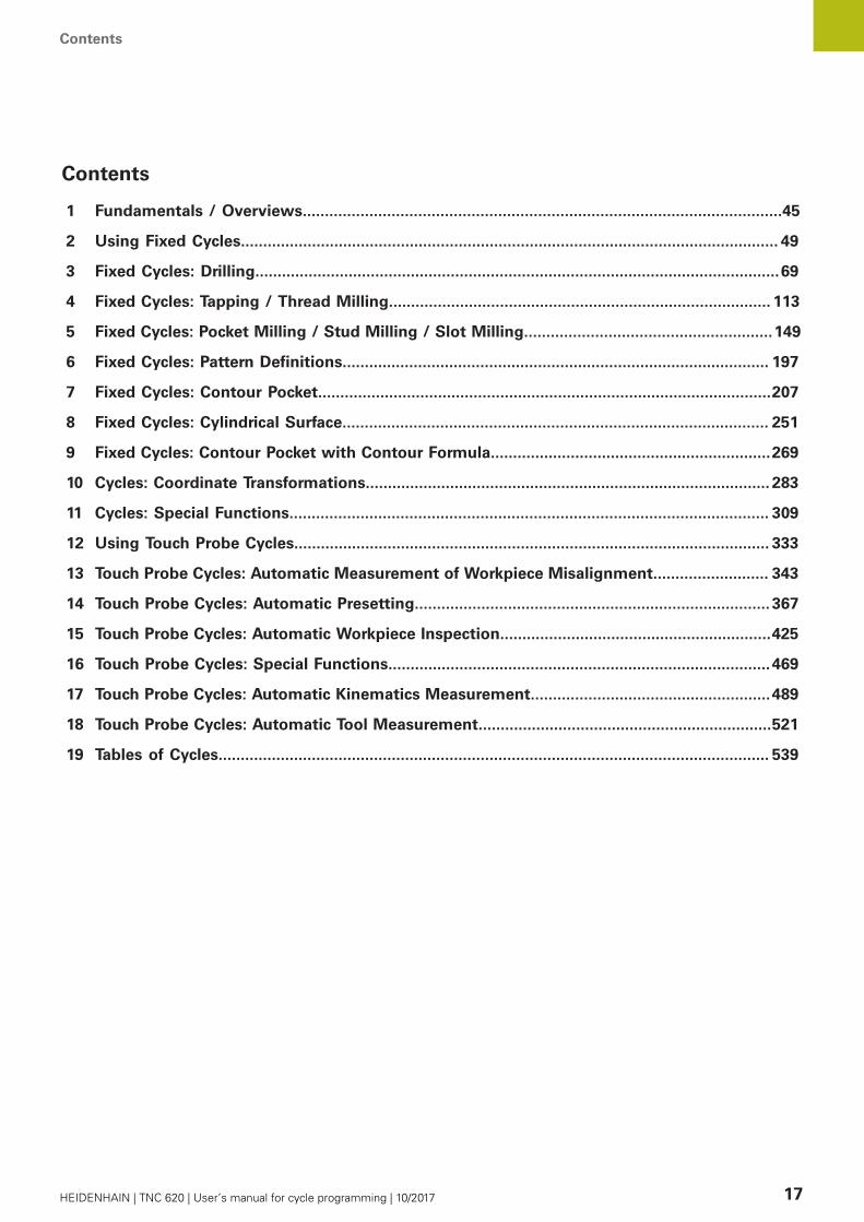
1 Fundamentals / Overviews............................................................................................................45
2 Using Fixed Cycles......................................................................................................................... 49
3 Fixed Cycles: Drilling......................................................................................................................69
4 Fixed Cycles: Tapping / Thread Milling...................................................................................... 113
5 Fixed Cycles: Pocket Milling / Stud Milling / Slot Milling........................................................149
6 Fixed Cycles: Pattern Definitions................................................................................................ 197
7 Fixed Cycles: Contour Pocket......................................................................................................207
8 Fixed Cycles: Cylindrical Surface................................................................................................ 251
9 Fixed Cycles: Contour Pocket with Contour Formula...............................................................269
10 Cycles: Coordinate Transformations........................................................................................... 283
11 Cycles: Special Functions............................................................................................................ 309
12 Using Touch Probe Cycles........................................................................................................... 333
13 Touch Probe Cycles: Automatic Measurement of Workpiece Misalignment.......................... 343
14 Touch Probe Cycles: Automatic Presetting................................................................................ 367
15 Touch Probe Cycles: Automatic Workpiece Inspection.............................................................425
16 Touch Probe Cycles: Special Functions......................................................................................469
17 Touch Probe Cycles: Automatic Kinematics Measurement......................................................489
18 Touch Probe Cycles: Automatic Tool Measurement..................................................................521
19 Tables of Cycles............................................................................................................................ 539

Contents
18 HEIDENHAIN | TNC 620 | User’s manual for cycle programming | 10/2017

Contents
HEIDENHAIN | TNC 620 | User’s manual for cycle programming | 10/2017 19
1 Fundamentals / Overviews............................................................................................................45
1.1 Introduction...........................................................................................................................................46
1.2 Available Cycle Groups........................................................................................................................47
Overview of fixed cycles....................................................................................................................... 47Overview of touch probe cycles............................................................................................................48

Contents
20 HEIDENHAIN | TNC 620 | User’s manual for cycle programming | 10/2017
2 Using Fixed Cycles......................................................................................................................... 49
2.1 Working with fixed cycles...................................................................................................................50
Machine-specific cycles (software option19)......................................................................................... 50Defining a cycle using soft keys............................................................................................................51Defining a cycle using the GOTO function............................................................................................ 51Calling a cycle........................................................................................................................................ 52
2.2 Program defaults for cycles................................................................................................................ 54
Overview................................................................................................................................................ 54Entering GLOBAL DEF...........................................................................................................................54Using GLOBAL DEF information........................................................................................................... 55Global data valid everywhere.................................................................................................................56Global data for drilling operations.......................................................................................................... 56Global data for milling operations with pocket cycles 25x.................................................................... 56Global data for milling operations with contour cycles..........................................................................56Global data for positioning behavior...................................................................................................... 57Global data for probing functions.......................................................................................................... 57
2.3 PATTERN DEF pattern definition........................................................................................................ 58
Application.............................................................................................................................................. 58Entering PATTERN DEF......................................................................................................................... 59Using PATTERN DEF..............................................................................................................................59Defining individual machining positions.................................................................................................60Defining a single row.............................................................................................................................60Defining a single pattern........................................................................................................................61Defining individual frames......................................................................................................................62Defining a full circle............................................................................................................................... 63Defining a pitch circle............................................................................................................................ 64
2.4 Point tables...........................................................................................................................................65
Application.............................................................................................................................................. 65Creating a point table............................................................................................................................ 65Hiding single points from the machining process................................................................................. 66Selecting a point table in the program.................................................................................................. 66Calling a cycle in connection with point tables..................................................................................... 67

Contents
HEIDENHAIN | TNC 620 | User’s manual for cycle programming | 10/2017 21
3 Fixed Cycles: Drilling......................................................................................................................69
3.1 Fundamentals....................................................................................................................................... 70
Overview................................................................................................................................................ 70
3.2 CENTERING (Cycle 240, DIN/ISO: G240, software option 19)......................................................... 71
Cycle run................................................................................................................................................ 71Please note while programming:...........................................................................................................71Cycle parameters................................................................................................................................... 72
3.3 DRILLING (Cycle 200)...........................................................................................................................73
Cycle run................................................................................................................................................ 73Please note while programming:...........................................................................................................73Cycle parameters................................................................................................................................... 74
3.4 REAMING (Cycle 201, DIN/ISO: G201, software option 19)............................................................. 75
Cycle run................................................................................................................................................ 75Please note while programming:...........................................................................................................75Cycle parameters................................................................................................................................... 76
3.5 BORING (Cycle 202, DIN/ISO: G202, software option 19)................................................................77
Cycle run................................................................................................................................................ 77Please note while programming:...........................................................................................................78Cycle parameters................................................................................................................................... 79
3.6 UNIVERSAL DRILLING (Cycle 203, DIN/ISO: G203, software option 19)........................................80
Cycle run................................................................................................................................................ 80Please note while programming:...........................................................................................................83Cycle parameters................................................................................................................................... 84
3.7 BACK BORING (Cycle 204, DIN/ISO: G204, software option 19).....................................................86
Cycle run................................................................................................................................................ 86Please note while programming:...........................................................................................................87Cycle parameters................................................................................................................................... 88
3.8 UNIVERSAL PECKING (Cycle 205, DIN/ISO: G205, software option 19).........................................90
Cycle run................................................................................................................................................ 90Please note while programming:...........................................................................................................91Cycle parameters................................................................................................................................... 92Position behavior when working with Q379..........................................................................................94
3.9 BORE MILLING (Cycle 208, software option 19)...............................................................................98
Cycle run................................................................................................................................................ 98Please note while programming:...........................................................................................................99Cycle parameters................................................................................................................................. 100

Contents
22 HEIDENHAIN | TNC 620 | User’s manual for cycle programming | 10/2017
3.10 SINGLE-LIP DEEP-HOLE DRILLING (Cycle 241, DIN/ISO: G241, software option 19)...................101
Cycle run.............................................................................................................................................. 101Please note while programming:.........................................................................................................102Cycle parameters................................................................................................................................. 103Position behavior when working with Q379........................................................................................105
3.11 Programming Examples.................................................................................................................... 109
Example: Drilling cycles....................................................................................................................... 109Example: Using drilling cycles in connection with PATTERN DEF.......................................................110

Contents
HEIDENHAIN | TNC 620 | User’s manual for cycle programming | 10/2017 23
4 Fixed Cycles: Tapping / Thread Milling...................................................................................... 113
4.1 Fundamentals..................................................................................................................................... 114
Overview.............................................................................................................................................. 114
4.2 TAPPING with a floating tap holder (Cycle 206, DIN/ISO: G206)..................................................115
Cycle run.............................................................................................................................................. 115Please note while programming:.........................................................................................................116Cycle parameters................................................................................................................................. 117
4.3 RIGID TAPPING without a floating tap holder (Cycle 207, DIN/ISO: G207).................................. 118
Cycle run.............................................................................................................................................. 118Please note while programming:.........................................................................................................119Cycle parameters................................................................................................................................. 120Retracting after a program interruption............................................................................................... 121
4.4 TAPPING WITH CHIP BREAKING (Cycle 209, DIN/ISO: G209, software option 19)......................122
Cycle run.............................................................................................................................................. 122Please note while programming:.........................................................................................................123Cycle parameters................................................................................................................................. 124
4.5 Fundamentals of Thread Milling...................................................................................................... 126
Prerequisites.........................................................................................................................................126
4.6 THREAD MILLING (Cycle 262, DIN/ISO: G262, software option 19)..............................................128
Cycle run.............................................................................................................................................. 128Please note while programming:.........................................................................................................129Cycle parameters................................................................................................................................. 130
4.7 THREAD MILLING/COUNTERSINKING (Cycle 263, DIN/ISO: G263, software option 19)............131
Cycle run.............................................................................................................................................. 131Please note while programming:.........................................................................................................132Cycle parameters................................................................................................................................. 133
4.8 THREAD DRILLING/MILLING (Cycle 264, DIN/ISO: G264, software option 19)............................135
Cycle run.............................................................................................................................................. 135Please note while programming:.........................................................................................................136Cycle parameters................................................................................................................................. 137
4.9 HELICAL THREAD DRILLING/MILLING (Cycle 265, DIN/ISO: G265, software option 19)............ 139
Cycle run.............................................................................................................................................. 139Please note while programming:.........................................................................................................140Cycle parameters................................................................................................................................. 141
4.10 OUTSIDE THREAD MILLING (Cycle 267, DIN/ISO: G267, software option 19).............................. 143
Cycle run.............................................................................................................................................. 143
Contents
24 HEIDENHAIN | TNC 620 | User’s manual for cycle programming | 10/2017
Please note while programming:.........................................................................................................144Cycle parameters................................................................................................................................. 145
4.11 Programming Examples.................................................................................................................... 147
Example: Thread milling.......................................................................................................................147
Contents
HEIDENHAIN | TNC 620 | User’s manual for cycle programming | 10/2017 25
5 Fixed Cycles: Pocket Milling / Stud Milling / Slot Milling........................................................149
5.1 Fundamentals..................................................................................................................................... 150
Overview.............................................................................................................................................. 150
5.2 RECTANGULAR POCKET (Cycle 251, DIN/ISO: G251, software option 19).................................. 151
Cycle run.............................................................................................................................................. 151Please note while programming:.........................................................................................................152Cycle parameters................................................................................................................................. 154
5.3 CIRCULAR POCKET (Cycle 252, DIN/ISO: G252, software option 19)...........................................156
Cycle run.............................................................................................................................................. 156Please note while programming:.........................................................................................................158Cycle parameters................................................................................................................................. 160
5.4 SLOT MILLING (Cycle 253, DIN/ISO: G253), Software Option 19..................................................162
Cycle run.............................................................................................................................................. 162Please note while programming:.........................................................................................................163Cycle parameters................................................................................................................................. 164
5.5 CIRCULAR SLOT (Cycle 254, DIN/ISO: G254, software option 19)................................................166
Cycle run.............................................................................................................................................. 166Please note while programming:.........................................................................................................167Cycle parameters................................................................................................................................. 169
5.6 RECTANGULAR STUD (Cycle 256, DIN/ISO: G256, software option 19)...................................... 172
Cycle run.............................................................................................................................................. 172Please note while programming:.........................................................................................................173Cycle parameters................................................................................................................................. 174
5.7 CIRCULAR STUD (Cycle 257, DIN/ISO: G257, software option 19)................................................ 177
Cycle run.............................................................................................................................................. 177Please note while programming:.........................................................................................................178Cycle parameters................................................................................................................................. 179
5.8 POLYGON STUD (Cycle 258, DIN/ISO: G258, software option 19)................................................181
Cycle run.............................................................................................................................................. 181Please note while programming:.........................................................................................................182Cycle parameters................................................................................................................................. 184
5.9 FACE MILLING (Cycle 233, DIN/ISO: G233, software option 19)................................................... 186
Cycle run.............................................................................................................................................. 186Please note while programming:.........................................................................................................190Cycle parameters................................................................................................................................. 191
5.10 Programming Examples.................................................................................................................... 194
Example: Milling pockets, studs and slots.......................................................................................... 194
Contents
26 HEIDENHAIN | TNC 620 | User’s manual for cycle programming | 10/2017
6 Fixed Cycles: Pattern Definitions................................................................................................ 197
6.1 Fundamentals..................................................................................................................................... 198
Overview.............................................................................................................................................. 198
6.2 POLAR PATTERN (Cycle 220, DIN/ISO: G220, software option 19)............................................... 199
Cycle run.............................................................................................................................................. 199Please note while programming:.........................................................................................................199Cycle parameters................................................................................................................................. 200
6.3 LINEAR PATTERN (Cycle 221, DIN/ISO: G221, software option 19).............................................. 202
Cycle run.............................................................................................................................................. 202Please note while programming:.........................................................................................................202Cycle parameters................................................................................................................................. 203
6.4 Programming Examples.................................................................................................................... 204
Example: Polar hole patterns............................................................................................................... 204
Contents
HEIDENHAIN | TNC 620 | User’s manual for cycle programming | 10/2017 27
7 Fixed Cycles: Contour Pocket......................................................................................................207
7.1 SL Cycles.............................................................................................................................................208
Fundamentals....................................................................................................................................... 208Overview.............................................................................................................................................. 210
7.2 CONTOUR (Cycle 14, DIN/ISO: G37)................................................................................................211
Please note while programming:.........................................................................................................211Cycle parameters................................................................................................................................. 211
7.3 Superimposed contours.................................................................................................................... 212
Fundamentals....................................................................................................................................... 212Subprograms: overlapping pockets...................................................................................................... 212Area of inclusion.................................................................................................................................. 213Area of exclusion................................................................................................................................. 214Area of intersection............................................................................................................................. 215
7.4 CONTOUR DATA (Cycle 20, DIN/ISO: G120, software option 19)..................................................216
Please note while programming:.........................................................................................................216Cycle parameters................................................................................................................................. 217
7.5 PILOT DRILLING (Cycle 21, DIN/ISO: G121, software option 19).................................................. 218
Cycle run.............................................................................................................................................. 218Please note while programming:.........................................................................................................219Cycle parameters................................................................................................................................. 219
7.6 ROUGHING (Cycle 22, DIN/ISO: G122, software option 19).......................................................... 220
Cycle run.............................................................................................................................................. 220Please note while programming:.........................................................................................................221Cycle parameters................................................................................................................................. 222
7.7 FLOOR FINISHING (Cycle 23, DIN/ISO: G123, software option 19)...............................................224
Cycle run.............................................................................................................................................. 224Please note while programming:.........................................................................................................225Cycle parameters................................................................................................................................. 225
7.8 SIDE FINISHING (Cycle 24, DIN/ISO: G124, software option 19).................................................. 226
Cycle run.............................................................................................................................................. 226Please note while programming:.........................................................................................................227Cycle parameters................................................................................................................................. 228
7.9 CONTOUR TRAIN (Cycle 25, DIN/ISO: G125, software option 19)................................................229
Cycle run.............................................................................................................................................. 229Please note while programming:.........................................................................................................230Cycle parameters................................................................................................................................. 231

Contents
28 HEIDENHAIN | TNC 620 | User’s manual for cycle programming | 10/2017
7.10 THREE-D CONT. TRAIN (Cycle 276, DIN/ISO: G276, software option 19)..................................... 233
Cycle run.............................................................................................................................................. 233Please note while programming:.........................................................................................................234Cycle parameters................................................................................................................................. 236
7.11 CONTOUR TRAIN DATA (Cycle 270, DIN/ISO: G270, software option 19).................................... 238
Please note while programming:.........................................................................................................238Cycle parameters................................................................................................................................. 239
7.12 TROCHOIDAL SLOT (Cycle 275, DIN/ISO: G275, software option 19)...........................................240
Cycle run.............................................................................................................................................. 240Please note while programming:.........................................................................................................242Cycle parameters................................................................................................................................. 243
7.13 Programming Examples.................................................................................................................... 245
Example: Roughing-out and fine-roughing a pocket............................................................................ 245Example: Pilot drilling, roughing-out and finishing overlapping contours.............................................247Example: Contour train........................................................................................................................ 249

Contents
HEIDENHAIN | TNC 620 | User’s manual for cycle programming | 10/2017 29
8 Fixed Cycles: Cylindrical Surface................................................................................................ 251
8.1 Fundamentals..................................................................................................................................... 252
Overview of cylindrical surface cycles.................................................................................................252
8.2 CYLINDER SURFACE (Cycle 27, DIN/ISO: G127, software option 1).............................................. 253
Cycle run.............................................................................................................................................. 253Please note while programming:.........................................................................................................254Cycle parameters................................................................................................................................. 255
8.3 CYLINDER SURFACE Slot milling (Cycle 28, DIN/ISO: G128, software option 1)........................ 256
Cycle run.............................................................................................................................................. 256Please note while programming:.........................................................................................................257Cycle parameters................................................................................................................................. 259
8.4 CYLINDER SURFACE Ridge milling (Cycle 29, DIN/ISO: G129, software option 1)......................260
Cycle run.............................................................................................................................................. 260Please note while programming:.........................................................................................................261Cycle parameters................................................................................................................................. 262
8.5 CYLINDER SURFACE (Cycle 39, DIN/ISO: G139, software option 1).............................................263
Cycle run.............................................................................................................................................. 263Please note while programming:.........................................................................................................264Cycle parameters................................................................................................................................. 265
8.6 Programming Examples.................................................................................................................... 266
Example: Cylinder surface with Cycle 27............................................................................................ 266Example: Cylinder surface with Cycle 28............................................................................................ 268

Contents
30 HEIDENHAIN | TNC 620 | User’s manual for cycle programming | 10/2017
9 Fixed Cycles: Contour Pocket with Contour Formula...............................................................269
9.1 SL cycles with complex contour formula........................................................................................270
Fundamentals....................................................................................................................................... 270Selecting a program with contour definitions......................................................................................272Defining contour descriptions.............................................................................................................. 272Entering a complex contour formula................................................................................................... 273Superimposed contours....................................................................................................................... 274Contour machining with SL Cycles......................................................................................................276Example: Roughing and finishing superimposed contours with the contour formula..........................277
9.2 SL cycles with simple contour formula...........................................................................................280
Fundamentals....................................................................................................................................... 280Entering a simple contour formula...................................................................................................... 282Contour machining with SL Cycles......................................................................................................282

Contents
HEIDENHAIN | TNC 620 | User’s manual for cycle programming | 10/2017 31
10 Cycles: Coordinate Transformations........................................................................................... 283
10.1 Fundamentals..................................................................................................................................... 284
Overview.............................................................................................................................................. 284Effectiveness of coordinate transformations....................................................................................... 284
10.2 DATUM SHIFT (Cycle 7, DIN/ISO: G54)............................................................................................ 285
Effect.................................................................................................................................................... 285Cycle parameters................................................................................................................................. 285Please note while programming..........................................................................................................285
10.3 DATUM SHIFT with datum tables (Cycle 7, DIN/ISO: G53)............................................................ 286
Effect.................................................................................................................................................... 286Please note while programming:.........................................................................................................287Cycle parameters................................................................................................................................. 287Selecting a datum table in the part program.......................................................................................288Editing the datum table in the Programming mode of operation........................................................ 288Configuring a datum table................................................................................................................... 290Leaving a datum table......................................................................................................................... 290Status displays..................................................................................................................................... 290
10.4 PRESETTING (Cycle 247, DIN/ISO: G247)........................................................................................ 291
Effect.................................................................................................................................................... 291Please note before programming:....................................................................................................... 291Cycle parameters................................................................................................................................. 291Status displays..................................................................................................................................... 291
10.5 MIRRORING (Cycle 8, DIN/ISO: G28)............................................................................................... 292
Effect.................................................................................................................................................... 292Please note while programming:.........................................................................................................293Cycle parameters................................................................................................................................. 293
10.6 ROTATION (Cycle 10, DIN/ISO: G73)................................................................................................ 294
Effect.................................................................................................................................................... 294Please note while programming:.........................................................................................................295Cycle parameters................................................................................................................................. 295
10.7 SCALING (Cycle 11, DIN/ISO: G72................................................................................................... 296
Effect.................................................................................................................................................... 296Cycle parameters................................................................................................................................. 296
10.8 AXIS-SPECIFIC SCALING (Cycle 26).................................................................................................297
Effect.................................................................................................................................................... 297Please note while programming:.........................................................................................................297Cycle parameters................................................................................................................................. 298

Contents
32 HEIDENHAIN | TNC 620 | User’s manual for cycle programming | 10/2017
10.9 WORKING PLANE (Cycle 19, DIN/ISO: G80, software option 1)....................................................299
Effect.................................................................................................................................................... 299Please note while programming:.........................................................................................................300Cycle parameters................................................................................................................................. 301Resetting.............................................................................................................................................. 301Positioning the axes of rotation...........................................................................................................302Position display in a tilted system....................................................................................................... 303Monitoring of the working space........................................................................................................ 303Positioning in a tilted coordinate system.............................................................................................304Combining coordinate transformation cycles.......................................................................................304Procedure for working with Cycle 19 WORKING PLANE.................................................................... 305
10.10 Programming Examples.................................................................................................................... 306
Example: Coordinate transformation cycles........................................................................................ 306

Contents
HEIDENHAIN | TNC 620 | User’s manual for cycle programming | 10/2017 33
11 Cycles: Special Functions............................................................................................................ 309
11.1 Fundamentals..................................................................................................................................... 310
Overview.............................................................................................................................................. 310
11.2 DWELL TIME (Cycle 9, DIN/ISO: G04)..............................................................................................311
Function................................................................................................................................................ 311Cycle parameters................................................................................................................................. 311
11.3 PROGRAM CALL (Cycle 12, DIN/ISO: G39)......................................................................................312
Cycle function.......................................................................................................................................312Please note while programming:.........................................................................................................312Cycle parameters................................................................................................................................. 312
11.4 SPINDLE ORIENTATION (Cycle 13, DIN/ISO: G36)..........................................................................313
Cycle function.......................................................................................................................................313Please note while programming:.........................................................................................................313Cycle parameters................................................................................................................................. 313
11.5 TOLERANCE (Cycle 32, DIN/ISO: G62).............................................................................................314
Cycle function.......................................................................................................................................314Influences of the geometry definition in the CAM system.................................................................314Please note while programming:.........................................................................................................315Cycle parameters................................................................................................................................. 316
11.6 ENGRAVING (Cycle 225, DIN/ISO: G225).........................................................................................317
Cycle run.............................................................................................................................................. 317Please note while programming:.........................................................................................................317Cycle parameters................................................................................................................................. 318Allowed engraving characters.............................................................................................................. 320Characters that cannot be printed....................................................................................................... 320Engraving system variables..................................................................................................................321Engraving the counter reading.............................................................................................................322
11.7 FACE MILLING (Cycle 232, DIN/ISO: G232, software option 19)................................................... 323
Cycle run.............................................................................................................................................. 323Please note while programming:.........................................................................................................325Cycle parameters................................................................................................................................. 326
11.8 ASCERTAIN THE LOAD (Cycle 239, DIN/ISO: G239, software option 143)................................... 328
Cycle run.............................................................................................................................................. 328Please note while programming:.........................................................................................................329Cycle parameters................................................................................................................................. 329
11.9 THREAD CUTTING (Cycle 18, DIN/ISO: G18, software option 19).................................................330
Cycle run.............................................................................................................................................. 330

Contents
34 HEIDENHAIN | TNC 620 | User’s manual for cycle programming | 10/2017
Please note while programming:.........................................................................................................330Cycle parameters................................................................................................................................. 331
Contents
HEIDENHAIN | TNC 620 | User’s manual for cycle programming | 10/2017 35
12 Using Touch Probe Cycles........................................................................................................... 333
12.1 General information about touch probe cycles.............................................................................. 334
Method of function.............................................................................................................................. 334Consideration of a basic rotation in the Manual Operation mode.......................................................335Touch probe cycles in the Manual Operation and Electronic Handwheel operating modes................ 335Touch probe cycles for automatic operation........................................................................................335
12.2 Before You Start Working with Touch Probe Cycles...................................................................... 337
Maximum traverse to touch point: DIST in touch probe table.............................................................337Set-up clearance to touch point: SET_UP in touch probe table...........................................................337Orient the infrared touch probe to the programmed probe direction: TRACK in touch probe table..... 337Touch trigger probe, probing feed rate: F in touch probe table........................................................... 338Touch trigger probe, rapid traverse for positioning: FMAX.................................................................. 338Touch trigger probe, rapid traverse for positioning: F_PREPOS in touch probe table.......................... 338Executing touch probe cycles.............................................................................................................. 339
12.3 Touch probe table.............................................................................................................................. 340
General information..............................................................................................................................340Editing touch probe tables...................................................................................................................340touch probe data..................................................................................................................................341

Contents
36 HEIDENHAIN | TNC 620 | User’s manual for cycle programming | 10/2017
13 Touch Probe Cycles: Automatic Measurement of Workpiece Misalignment.......................... 343
13.1 Fundamentals..................................................................................................................................... 344
Overview.............................................................................................................................................. 344Characteristics common to all touch probe cycles for measuring workpiece misalignment................346
13.2 BASIC ROTATION (Cycle 400, DIN/ISO: G400, software option 17).............................................. 347
Cycle run.............................................................................................................................................. 347Please note while programming:.........................................................................................................347Cycle parameters................................................................................................................................. 348
13.3 BASIC ROTATION over two holes (Cycle 401, DIN/ISO: G401, software option 17)..................... 350
Cycle run.............................................................................................................................................. 350Please note while programming:.........................................................................................................351Cycle parameters................................................................................................................................. 352
13.4 BASIC ROTATION over two studs (Cycle 402, DIN/ISO: G402, software option 17).................... 354
Cycle run.............................................................................................................................................. 354Please note while programming:.........................................................................................................355Cycle parameters................................................................................................................................. 356
13.5 BASIC ROTATION compensation via rotary axis (Cycle 403, DIN/ISO: G403, software option17).........................................................................................................................................................358
Cycle run.............................................................................................................................................. 358Please note while programming:.........................................................................................................359Cycle parameters................................................................................................................................. 360
13.6 SET BASIC ROTATION (Cycle 404, DIN/ISO: G404, software option 17).......................................362
Cycle run.............................................................................................................................................. 362Cycle parameters................................................................................................................................. 362
13.7 Compensating workpiece misalignment by rotating the C axis (Cycle 405, DIN/ISO: G405,software option 17)............................................................................................................................363
Cycle run.............................................................................................................................................. 363Please note while programming:.........................................................................................................364Cycle parameters................................................................................................................................. 365
13.8 Example: Determining a basic rotation from two holes................................................................366

Contents
HEIDENHAIN | TNC 620 | User’s manual for cycle programming | 10/2017 37
14 Touch Probe Cycles: Automatic Presetting................................................................................ 367
14.1 Fundamentals..................................................................................................................................... 368
Overview.............................................................................................................................................. 368Characteristics common to all touch probe cycles for presetting........................................................370
14.2 SLOT CENTER PRESET (Cycle 408, DIN/ISO: G408, software option 17)......................................372
Cycle run.............................................................................................................................................. 372Please note while programming:.........................................................................................................373Cycle parameters................................................................................................................................. 374
14.3 RIDGE CENTER PRESET (Cycle 409, DIN/ISO: G409, software option 17)....................................376
Cycle run.............................................................................................................................................. 376Please note while programming:.........................................................................................................377Cycle parameters................................................................................................................................. 378
14.4 PRESET FROM INSIDE OF RECTANGLE (Cycle 410, DIN/ISO: G410, software option 17)........... 380
Cycle run.............................................................................................................................................. 380Please note while programming:.........................................................................................................381Cycle parameters................................................................................................................................. 382
14.5 PRESET FROM OUTSIDE OF RECTANGLE (Cycle 411, DIN/ISO: G411, software option 17)........384
Cycle run.............................................................................................................................................. 384Please note while programming:.........................................................................................................385Cycle parameters................................................................................................................................. 386
14.6 PRESET FROM INSIDE OF CIRCLE (Cycle 412, DIN/ISO: G412, software option 17)................... 388
Cycle run.............................................................................................................................................. 388Please note while programming:.........................................................................................................389Cycle parameters................................................................................................................................. 390
14.7 PRESET FROM OUTSIDE OF CIRCLE (Cycle 413, DIN/ISO: G413, software option 17)............... 393
Cycle run.............................................................................................................................................. 393Please note while programming:.........................................................................................................394Cycle parameters................................................................................................................................. 395
14.8 PRESET FROM OUTSIDE OF CORNER (Cycle 414, DIN/ISO: G414, software option 17).............398
Cycle run.............................................................................................................................................. 398Please note while programming:.........................................................................................................399Cycle parameters................................................................................................................................. 400
14.9 PRESET FROM INSIDE OF CORNER (Cycle 415, DIN/ISO: G415, software option 17).................403
Cycle run.............................................................................................................................................. 403Please note while programming:.........................................................................................................404Cycle parameters................................................................................................................................. 405

Contents
38 HEIDENHAIN | TNC 620 | User’s manual for cycle programming | 10/2017
14.10 PRESET CIRCLE CENTER (Cycle 416, DIN/ISO: G416, software option 17).................................. 408
Cycle run.............................................................................................................................................. 408Please note while programming:.........................................................................................................409Cycle parameters................................................................................................................................. 410
14.11 PRESET IN TOUCH PROBE AXIS (Cycle 417, DIN/ISO: G417, software option 17)....................... 412
Cycle run.............................................................................................................................................. 412Please note while programming:.........................................................................................................412Cycle parameters................................................................................................................................. 413
14.12 PRESET AT CENTER OF 4 HOLES (Cycle 418, DIN/ISO: G418, software option 17).....................414
Cycle run.............................................................................................................................................. 414Please note while programming:.........................................................................................................415Cycle parameters................................................................................................................................. 416
14.13 PRESET IN ONE AXIS (Cycle 419, DIN/ISO: G419, software option 17)....................................... 418
Cycle run.............................................................................................................................................. 418Please note while programming:.........................................................................................................418Cycle parameters................................................................................................................................. 419
14.14 Example: Presetting in center of a circular segment and on top surface of workpiece.............. 421
14.15 Example: Presetting on top surface of workpiece and in center of a bolt hole circle..................422

Contents
HEIDENHAIN | TNC 620 | User’s manual for cycle programming | 10/2017 39
15 Touch Probe Cycles: Automatic Workpiece Inspection.............................................................425
15.1 Fundamentals..................................................................................................................................... 426
Overview.............................................................................................................................................. 426Recording the results of measurement...............................................................................................427Measurement results in Q parameters............................................................................................... 429Classification of results........................................................................................................................429Tolerance monitoring............................................................................................................................429Tool monitoring.....................................................................................................................................430Reference system for measurement results....................................................................................... 431
15.2 REFERENCE PLANE (Cycle 0, DIN/ISO: G55, software option 17)................................................ 432
Cycle run.............................................................................................................................................. 432Please note while programming:.........................................................................................................432Cycle parameters................................................................................................................................. 432
15.3 POLAR PRESET (Cycle 1, software option 17)................................................................................ 433
Cycle run.............................................................................................................................................. 433Please note while programming:.........................................................................................................433Cycle parameters................................................................................................................................. 433
15.4 MEASURE ANGLE (Cycle 420, DIN/ISO: G420, software option 17).............................................434
Cycle run.............................................................................................................................................. 434Please note while programming:.........................................................................................................434Cycle parameters................................................................................................................................. 435
15.5 MEASURE HOLE (Cycle 421, DIN/ISO: G421, software option 17)................................................437
Cycle run.............................................................................................................................................. 437Please note while programming:.........................................................................................................437Cycle parameters................................................................................................................................. 438
15.6 MEASURE HOLE OUTSIDE (Cycle 422, DIN/ISO: G422, software option 17)...............................441
Cycle run.............................................................................................................................................. 441Please note while programming:.........................................................................................................441Cycle parameters................................................................................................................................. 442
15.7 MEASURE RECTANGLE INSIDE (Cycle 423, DIN/ISO: G423, software option 17)....................... 445
Cycle run.............................................................................................................................................. 445Please note while programming:.........................................................................................................445Cycle parameters................................................................................................................................. 446
15.8 MEASURE RECTANGLE OUTSIDE (Cycle 424, DIN/ISO: G424, software option 17)....................448
Cycle run.............................................................................................................................................. 448Please note while programming:.........................................................................................................448Cycle parameters................................................................................................................................. 449

Contents
40 HEIDENHAIN | TNC 620 | User’s manual for cycle programming | 10/2017
15.9 MEASURE INSIDE WIDTH (Cycle 425, DIN/ISO: G425, software option 17)................................ 451
Cycle run.............................................................................................................................................. 451Please note while programming:.........................................................................................................451Cycle parameters................................................................................................................................. 452
15.10 MEASURE RIDGE WIDTH (Cycle 426, DIN/ISO: G426, software option 17)................................. 454
Cycle run.............................................................................................................................................. 454Please note while programming:.........................................................................................................454Cycle parameters................................................................................................................................. 455
15.11 MEASURE COORDINATE (Cycle 427, DIN/ISO: G427, software option 17)................................... 457
Cycle run.............................................................................................................................................. 457Please note while programming:.........................................................................................................457Cycle parameters................................................................................................................................. 458
15.12 MEASURE BOLT HOLE CIRCLE (Cycle 430, DIN/ISO: G430, software option 17).........................460
Cycle run.............................................................................................................................................. 460Please note while programming:.........................................................................................................461Cycle parameters................................................................................................................................. 461
15.13 MEASURE PLANE (Cycle 431, DIN/ISO: G431, software option 17)............................................. 463
Cycle run.............................................................................................................................................. 463Please note while programming:.........................................................................................................464Cycle parameters................................................................................................................................. 464
15.14 Programming Examples.................................................................................................................... 466
Example: Measuring and reworking a rectangular stud...................................................................... 466Example: Measuring a rectangular pocket and recording the results..................................................468
Contents
HEIDENHAIN | TNC 620 | User’s manual for cycle programming | 10/2017 41
16 Touch Probe Cycles: Special Functions......................................................................................469
16.1 Fundamentals..................................................................................................................................... 470
Overview.............................................................................................................................................. 470
16.2 MEASURE (Cycle 3, software option 17).........................................................................................471
Cycle run.............................................................................................................................................. 471Please note while programming:.........................................................................................................471Cycle parameters................................................................................................................................. 472
16.3 MEASURING IN 3-D (Cycle 4, software option 17).........................................................................473
Cycle run.............................................................................................................................................. 473Please note while programming:.........................................................................................................473Cycle parameters................................................................................................................................. 474
16.4 Calibrating a touch trigger probe.....................................................................................................475
16.5 Displaying calibration values............................................................................................................ 476
16.6 CALIBRATE TS (Cycle 460, DIN/ISO: G460, software option 17)................................................... 477
16.7 CALIBRATE TS LENGTH (Cycle 461, DIN/ISO: G461, software option 17)....................................481
16.8 CALIBRATE TS RADIUS INSIDE (Cycle 462, DIN/ISO: G462, software option 17)........................483
16.9 CALIBRATE TS RADIUS OUTSIDE (Cycle 463, DIN/ISO: G463, software option 17)....................485
16.10 FAST PROBING (Cycle 441, DIN/ISO G441, software option 17)...................................................487
Cycle run.............................................................................................................................................. 487Please note while programming:.........................................................................................................487Cycle parameters................................................................................................................................. 488

Contents
42 HEIDENHAIN | TNC 620 | User’s manual for cycle programming | 10/2017
17 Touch Probe Cycles: Automatic Kinematics Measurement......................................................489
17.1 Kinematics measurement with TS touch probes (KinematicsOpt option)...................................490
Fundamentals....................................................................................................................................... 490Overview.............................................................................................................................................. 490
17.2 Prerequisites........................................................................................................................................491
Please note while programming:.........................................................................................................492
17.3 SAVE KINEMATICS (Cycle 450, DIN/ISO: G450, option).................................................................493
Cycle run.............................................................................................................................................. 493Please note while programming:.........................................................................................................493Cycle parameters................................................................................................................................. 494Logging function.................................................................................................................................. 494Notes on data management................................................................................................................495
17.4 MEASURE KINEMATICS (Cycle 451, DIN/ISO: G451, option)........................................................ 496
Cycle run.............................................................................................................................................. 496Positioning direction............................................................................................................................. 498Machines with Hirth-coupled axes.......................................................................................................499Choice of number of measuring points...............................................................................................500Choice of the calibration sphere position on the machine table......................................................... 501Notes on the accuracy.........................................................................................................................501Notes on various calibration methods................................................................................................. 502Backlash................................................................................................................................................503Please note while programming:.........................................................................................................504Cycle parameters................................................................................................................................. 505Various modes (Q406)......................................................................................................................... 508Logging function.................................................................................................................................. 509
17.5 PRESET COMPENSATION (Cycle 452, DIN/ISO: G452, option)..................................................... 510
Cycle run.............................................................................................................................................. 510Please note while programming:.........................................................................................................512Cycle parameters................................................................................................................................. 513Adjustment of interchangeable heads................................................................................................. 515Drift compensation...............................................................................................................................517Logging function.................................................................................................................................. 519

Contents
HEIDENHAIN | TNC 620 | User’s manual for cycle programming | 10/2017 43
18 Touch Probe Cycles: Automatic Tool Measurement..................................................................521
18.1 Fundamentals..................................................................................................................................... 522
Overview.............................................................................................................................................. 522Differences between Cycles 31 to 33 and Cycles 481 to 483............................................................ 523Setting machine parameters................................................................................................................ 524Entries in the tool table TOOL.T..........................................................................................................526
18.2 Calibrating the TT (Cycle 30 or 480, DIN/ISO: G480 option 17).................................................... 528
Cycle run.............................................................................................................................................. 528Please note while programming:.........................................................................................................529Cycle parameters................................................................................................................................. 529
18.3 Calibrating the wireless TT 449 (Cycle 484, DIN/ISO: G484, Option 17).......................................530
Fundamentals....................................................................................................................................... 530Cycle run.............................................................................................................................................. 530Please note while programming:.........................................................................................................531Cycle parameters................................................................................................................................. 531
18.4 Measuring tool length (Cycle 31 or 481, DIN/ISO: G481, Option 17)............................................532
Cycle run.............................................................................................................................................. 532Please note while programming:.........................................................................................................533Cycle parameters................................................................................................................................. 533
18.5 Measuring tool radius (Cycle 32 or 482, DIN/ISO: G482, Option 17)............................................ 534
Cycle run.............................................................................................................................................. 534Please note while programming:.........................................................................................................534Cycle parameters................................................................................................................................. 535
18.6 Measuring tool length and radius (Cycle 33 or 483, DIN/ISO: G483, Option 17)......................... 536
Cycle run.............................................................................................................................................. 536Please note while programming:.........................................................................................................536Cycle parameters................................................................................................................................. 537

Contents
44 HEIDENHAIN | TNC 620 | User’s manual for cycle programming | 10/2017
19 Tables of Cycles............................................................................................................................ 539
19.1 Overview............................................................................................................................................. 540
Fixed cycles..........................................................................................................................................540Touch probe cycles...............................................................................................................................542

1Fundamentals /
Overviews
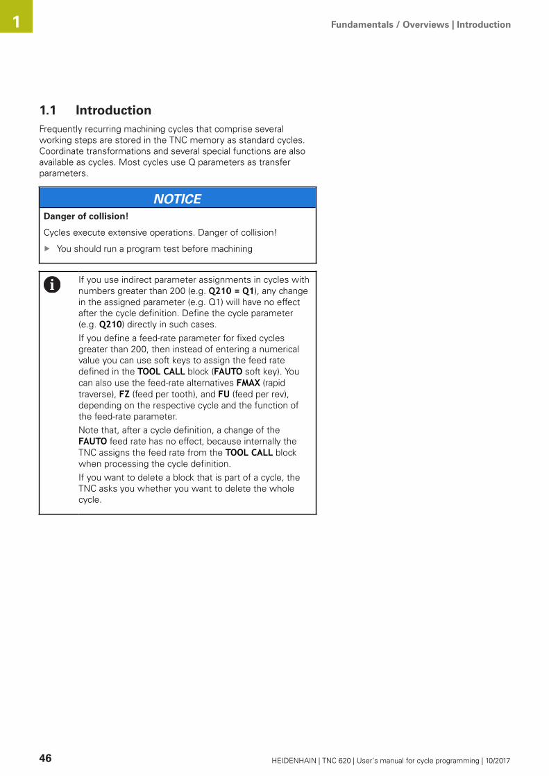
Fundamentals / Overviews | Introduction 1
46 HEIDENHAIN | TNC 620 | User’s manual for cycle programming | 10/2017
1.1 IntroductionFrequently recurring machining cycles that comprise severalworking steps are stored in the TNC memory as standard cycles.Coordinate transformations and several special functions are alsoavailable as cycles. Most cycles use Q parameters as transferparameters.
NOTICEDanger of collision!
Cycles execute extensive operations. Danger of collision!
You should run a program test before machining
If you use indirect parameter assignments in cycles withnumbers greater than 200 (e.g. Q210 = Q1), any changein the assigned parameter (e.g. Q1) will have no effectafter the cycle definition. Define the cycle parameter(e.g. Q210) directly in such cases.If you define a feed-rate parameter for fixed cyclesgreater than 200, then instead of entering a numericalvalue you can use soft keys to assign the feed ratedefined in the TOOL CALL block (FAUTO soft key). Youcan also use the feed-rate alternatives FMAX (rapidtraverse), FZ (feed per tooth), and FU (feed per rev),depending on the respective cycle and the function ofthe feed-rate parameter.Note that, after a cycle definition, a change of theFAUTO feed rate has no effect, because internally theTNC assigns the feed rate from the TOOL CALL blockwhen processing the cycle definition.If you want to delete a block that is part of a cycle, theTNC asks you whether you want to delete the wholecycle.
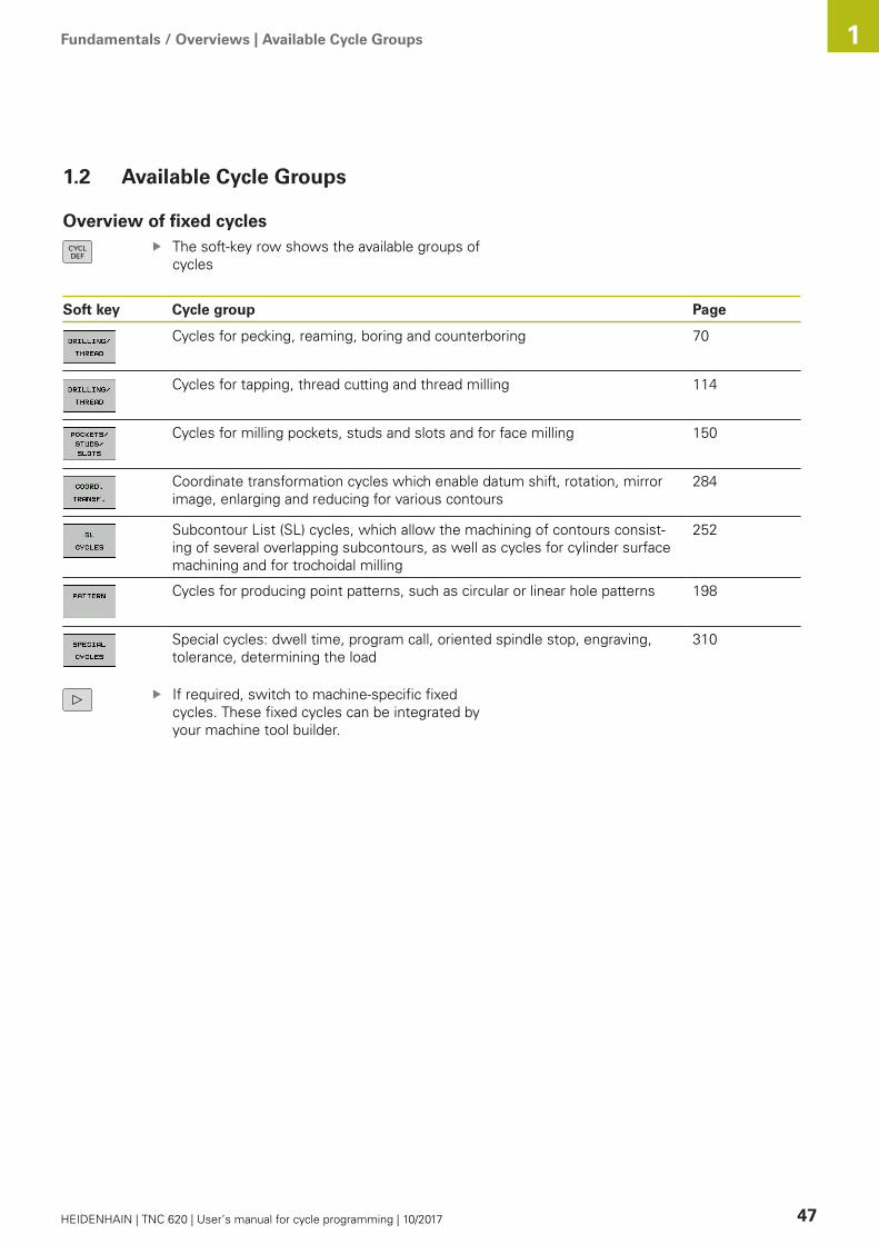
Fundamentals / Overviews | Available Cycle Groups 1
HEIDENHAIN | TNC 620 | User’s manual for cycle programming | 10/2017 47
1.2 Available Cycle Groups
Overview of fixed cyclesThe soft-key row shows the available groups ofcycles
Soft key Cycle group Page
Cycles for pecking, reaming, boring and counterboring 70
Cycles for tapping, thread cutting and thread milling 114
Cycles for milling pockets, studs and slots and for face milling 150
Coordinate transformation cycles which enable datum shift, rotation, mirrorimage, enlarging and reducing for various contours
284
Subcontour List (SL) cycles, which allow the machining of contours consist-ing of several overlapping subcontours, as well as cycles for cylinder surfacemachining and for trochoidal milling
252
Cycles for producing point patterns, such as circular or linear hole patterns 198
Special cycles: dwell time, program call, oriented spindle stop, engraving,tolerance, determining the load
310
If required, switch to machine-specific fixedcycles. These fixed cycles can be integrated byyour machine tool builder.

Fundamentals / Overviews | Available Cycle Groups 1
48 HEIDENHAIN | TNC 620 | User’s manual for cycle programming | 10/2017
Overview of touch probe cyclesThe soft-key row shows the available groups ofcycles
Soft key Cycle group Page
Cycles for automatic measurement and compensation of workpiecemisalignment
344
Cycles for automatic workpiece presetting 368
Cycles for automatic workpiece inspection 426
Special cycles 470
Touch probe calibration 477
Cycles for automatic kinematics measurement 344
Cycles for automatic tool measurement (enabled by the machine toolbuilder)
522
If required, switch to machine-specific touchprobe cycles. These touch probe cycles can beintegrated by your machine tool builder.

2Using Fixed Cycles

Using Fixed Cycles | Working with fixed cycles 2
50 HEIDENHAIN | TNC 620 | User’s manual for cycle programming | 10/2017
2.1 Working with fixed cycles
Machine-specific cycles (software option19)In addition to the HEIDENHAIN cycles, many machine tool buildersoffer their own cycles in the TNC. These cycles are available in aseparate cycle-number range:
Cycles 300 to 399 Machine-specific cycles that are to be defined through theCYCLE DEF keyCycles 500 to 599 Machine-specific touch probe cycles that are to be definedthrough the TOUCH PROBE key
Refer to your machine manual for a description of thespecific function.
Sometimes machine-specific cycles use transfer parameters thatHEIDENHAIN already uses in standard cycles. For parallel use ofDEF active cycles (cycles that the TNC is automatically runningduring cycle definition) and CALL active cycles (cycles that youneed to call up to run).Further information: "Calling a cycle", Page 52Adhere to the following procedure in order to avoid problemsregarding the overwriting of transfer parameters that are usedmore than once:
As a rule, always program DEF-active cycles before CALL-activecyclesIf you do want to program a DEF-active cycle between thedefinition and call of a CALL-active cycle, do it only if there is nocommon use of specific transfer parameters

Using Fixed Cycles | Working with fixed cycles 2
HEIDENHAIN | TNC 620 | User’s manual for cycle programming | 10/2017 51
Defining a cycle using soft keysThe soft-key row shows the available groups ofcycles
Press the soft key for the desired group ofcycles, for example DRILLING for the drillingcycles
Select the cycle, e.g. THREAD MILLING. The TNCinitiates the programming dialog and asks for allrequired input values. At the same time a graphicof the input parameters is displayed in the rightscreen window. The parameter that is asked forin the dialog prompt is highlighted.Enter all parameters requested by the TNC andconclude each entry with the ENT keyThe TNC ends the dialog when all required datahas been entered
Defining a cycle using the GOTO functionThe soft-key row shows the available groups ofcycles
The TNC shows an overview of cycles in a pop-up windowChoose the desired cycle with the arrow keys, orEnter the cycle number and confirm it with theENT key. The TNC then initiates the cycle dialogas described above
Example NC blocks
7 CYCL DEF 200 DRILLING
Q200=2 ;SET-UP CLEARANCE
Q201=3 ;DEPTH
Q206=150 ;FEED RATE FOR PLNGNG
Q202=5 ;PLUNGING DEPTH
Q210=0 ;DWELL TIME AT TOP
Q203=+0 ;SURFACE COORDINATE
Q204=50 ;2ND SET-UP CLEARANCE
Q211=0.25 ;DWELL TIME AT DEPTH
Q395=0 ;DEPTH REFERENCE
Using Fixed Cycles | Working with fixed cycles 2
52 HEIDENHAIN | TNC 620 | User’s manual for cycle programming | 10/2017
Calling a cycle
Requirements
The following data must always be programmed beforea cycle call:
BLK FORM for graphic display (needed only for testgraphics)Tool callDirection of spindle rotation (M functions M3/M4)Cycle definition (CYCL DEF)
For some cycles, additional prerequisites must beobserved. They are detailed in the descriptions for eachcycle.
The following cycles become effective automatically as soon asthey are defined in the part program. These cycles cannot andmust not be called:
Cycle 220 for point patterns on circles and Cycle 221 for pointpatterns on linesSL Cycle 14 CONTOURSL Cycle 20 CONTOUR DATACycle 32 TOLERANCECoordinate transformation cyclesCycle 9 DWELL TIMEAll touch probe cycles
You can call all other cycles with the functions described as follows.
Calling a cycle with CYCL CALL
The CYCL CALL function calls the most recently defined fixedcycle once. The starting point of the cycle is the position that wasprogrammed last before the CYCL CALL block.
To program the cycle call, press the CYCL CALLkeyPress the CYCL CALL M soft key to enter a cyclecallIf necessary, enter the miscellaneous function M(for example M3 to switch the spindle on), or endthe dialog by pressing the END key
Calling a cycle with CYCL CALL PAT
The CYCL CALL PAT function calls the most recently definedmachining cycle at all positions that you defined in a PATTERN DEFpattern definition or in a points table.Further information: "PATTERN DEF pattern definition",Page 58Further information: "Point tables", Page 65

Using Fixed Cycles | Working with fixed cycles 2
HEIDENHAIN | TNC 620 | User’s manual for cycle programming | 10/2017 53
Calling a cycle with CYCL CALL POS
The CYCL CALL POS function calls the most recently defined fixedcycle once. The starting point of the cycle is the position that youdefined in the CYCL CALL POS block.Using positioning logic the TNC moves to the position defined inthe CYCL CALL POS block.
If the tool’s current position in the tool axis is greater than thetop surface of the workpiece (Q203), the TNC moves the tool tothe programmed position first in the machining plane and thenin the tool axis.If the tool’s current position in the tool axis is below the topsurface of the workpiece (Q203), the TNC moves the tool tothe programmed position first in the tool axis to the clearanceheight and then in the working plane to the programmedposition.
Three coordinate axes must always be programmed inthe CYCL CALL POS block. With the coordinate in thetool axis you can easily change the starting position. Itserves as an additional datum shift.The feed rate most recently defined in the CYCL CALLPOS block applies only for traverse to the start positionprogrammed in this block.Using positioning logic the TNC moves to the positiondefined in the CYCL CALL POS block:If you use CYCL CALL POS to call a cycle in which a startposition is defined (for example Cycle 212), then theposition defined in the cycle serves as an additional shiftof the position defined in the CYCL CALL POS block. Youshould therefore always define the start position to beset in the cycle as 0.
Cycle call with M99/M89
The M99 function, which is active only in the block in which itis programmed, calls the last defined fixed cycle once. You canprogram M99 at the end of a positioning block. The TNC moves tothis position and then calls the last defined fixed cycle.If the TNC is to run the cycle automatically after every positioningblock, program the first cycle call with M89.To cancel the effect of M89, program:
M99 in the positioning block in which you move to the laststarting point, orUse CYCL DEF to define a new fixed cycle

Using Fixed Cycles | Program defaults for cycles 2
54 HEIDENHAIN | TNC 620 | User’s manual for cycle programming | 10/2017
2.2 Program defaults for cycles
OverviewAll Cycles 20 to 25, as well as all of those with numbers 200 orhigher, always use identical cycle parameters, such as the set-upclearance Q200, which you must enter for each cycle definition.The GLOBAL DEF function gives you the possibility of definingthese cycle parameters at the beginning of the program, so thatthey are effective globally for all machining cycles used in theprogram. In the respective machining cycle you then simply link tothe value defined at the beginning of the program.The following GLOBAL DEF functions are available:
Soft key Machining patterns Page
GLOBAL DEF COMMON Definition of generally valid cycleparameters
56
GLOBAL DEF DRILLING Definition of specific drilling cycleparameters
56
GLOBAL DEF POCKET MILLINGDefinition of specific pocket-millingcycle parameters
56
GLOBAL DEF CONTOUR MILLING Definition of specific contour millingcycle parameters
56
GLOBAL DEF POSITIONING Definition of the positioning behaviorfor CYCL CALL PAT
57
GLOBAL DEF PROBING Definition of specific touch probecycle parameters
57
Entering GLOBAL DEFMode of operation: Press the Programming key
Press the SPEC FCT key to select the specialfunctions
Select the functions for program defaults
Press the GLOBAL DEF soft key
Select the desired GLOBAL DEF function, e.g. bypressing the GLOBAL DEF GENERAL soft keyEnter the required definitions, and confirm eachentry with the ENT key

Using Fixed Cycles | Program defaults for cycles 2
HEIDENHAIN | TNC 620 | User’s manual for cycle programming | 10/2017 55
Using GLOBAL DEF informationIf you entered the respective GLOBAL DEF functions at the startof the program, you can reference these globally valid values whendefining any machining cycle.Proceed as follows:
Operating mode: Press the Programming key
Select machining cycles: Press the CYCLE DEFkey
Select the desired cycle group, e.g. drillingcycles
Select the desired cycle, e.g. drillingIf there is a global parameter for this the TNCdisplays the SET STANDARD VALUES soft key
Press the SET STANDARD VALUES soft key:The TNC inputs the word PREDEF in the cycledefinition. You have now created a link to thecorresponding GLOBAL DEF parameter that youdefined at the beginning of the program
NOTICEDanger of collision!
If you modify the program settings later with GLOBAL DEF themodifications are effective on the complete machining program.As a consequence the machining sequence can significantlydiffer.
Use GLOBAL DEF intentionally and run a program test beforemachiningIf a fixed value is entered in machining cycles, GLOBAL DEFdoes not modify this value
Using Fixed Cycles | Program defaults for cycles 2
56 HEIDENHAIN | TNC 620 | User’s manual for cycle programming | 10/2017
Global data valid everywhereSafety clearance: Distance between tool tip and workpiecesurface for automated approach of the cycle start position in thetool axis2nd set-up clearance: Position to which the TNC positions thetool at the end of a machining step. The next machining positionis approached at this height in the machining planeF positioning: Feed rate at which the TNC traverses the toolwithin a cycleF retraction: Feed rate at which the TNC retracts the tool.
The parameters are valid for all fixed cycles withnumbers greater than 2xx.
Global data for drilling operationsRetraction rate for chip breaking: Value by which the TNCretracts the tool during chip breakingDwell time at depth: Time in seconds that the tool remains atthe hole bottomDwell time at top: Time in seconds that the tool remains at theset-up clearance
The parameters apply to the drilling, tapping and threadmilling cycles 200 to 209, 240, 241 and 262 to 267.
Global data for milling operations with pocket cycles25x
Overlap factor: The tool radius multiplied by the overlap factorequals the lateral stepoverClimb or up-cut: Select the type of millingPlunging type: Plunge into the material helically, in areciprocating motion, or vertically
The parameters apply to milling cycles 251 to 257.
Global data for milling operations with contour cyclesSet-up clearance: Distance between tool face and workpiecesurface for automated approach of the cycle start position in thetool axisClearance height: Absolute height at which the tool cannotcollide with the workpiece (for intermediate positioning andretraction at the end of the cycle)Overlap factor: The tool radius multiplied by the overlap factorequals the lateral stepoverClimb or up-cut: Select the type of milling
The parameters apply to SL cycles 20, 22, 23, 24 and25.
Using Fixed Cycles | Program defaults for cycles 2
HEIDENHAIN | TNC 620 | User’s manual for cycle programming | 10/2017 57
Global data for positioning behaviorPositioning behavior: Retraction in the tool axis at the end ofthe machining step: Return to the 2nd set-up clearance or to theposition at the beginning of the unit
The parameters apply to each fixed cycle that you callwith the CYCL CALL PAT function.
Global data for probing functionsSet-up clearance: Distance between stylus and workpiecesurface for automated approach of the probing positionClearance height: The coordinate in the touch probe axis towhich the TNC traverses the touch probe between measuringpoints, if the Move to clearance height option is activatedMove to clearance height: Select whether the TNC movesthe touch probe to the set-up clearance or clearance heightbetween the measuring points
The parameters apply to all touch probe cyclesnumbered 4xx.
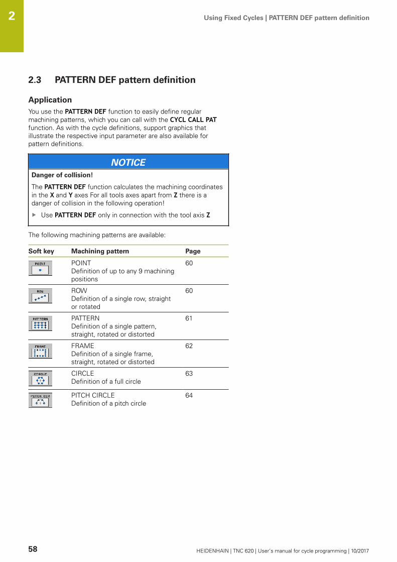
Using Fixed Cycles | PATTERN DEF pattern definition 2
58 HEIDENHAIN | TNC 620 | User’s manual for cycle programming | 10/2017
2.3 PATTERN DEF pattern definition
ApplicationYou use the PATTERN DEF function to easily define regularmachining patterns, which you can call with the CYCL CALL PATfunction. As with the cycle definitions, support graphics thatillustrate the respective input parameter are also available forpattern definitions.
NOTICEDanger of collision!
The PATTERN DEF function calculates the machining coordinatesin the X and Y axes For all tools axes apart from Z there is adanger of collision in the following operation!
Use PATTERN DEF only in connection with the tool axis Z
The following machining patterns are available:
Soft key Machining pattern Page
POINT Definition of up to any 9 machiningpositions
60
ROW Definition of a single row, straightor rotated
60
PATTERN Definition of a single pattern,straight, rotated or distorted
61
FRAME Definition of a single frame,straight, rotated or distorted
62
CIRCLE Definition of a full circle
63
PITCH CIRCLE Definition of a pitch circle
64

Using Fixed Cycles | PATTERN DEF pattern definition 2
HEIDENHAIN | TNC 620 | User’s manual for cycle programming | 10/2017 59
Entering PATTERN DEFMode of operation: Press the Programming key
Press the SPEC FCT key to select the specialfunctions
Select the functions for contour and pointmachining
Press the PATTERN DEF soft key
Select the desired machining pattern, e.g. pressthe "single row" soft keyEnter the required definitions, and confirm eachentry with the ENT key
Using PATTERN DEFAs soon as you have entered a pattern definition, you can call itwith the CYCL CALL PAT function.Further information: "Calling a cycle", Page 52The TNC then performs the most recently defined machining cycleon the machining pattern you defined.
A machining pattern remains active until you define anew one, or select a point table with the SEL PATTERNfunction.The TNC retracts the tool to the clearance heightbetween the starting points. Depending on which isgreater, the TNC uses either the spindle axis coordinatefrom the cycle call or the value from cycle parameterQ204 as the clearance height.Before CYCL CALL PAT you can use the functionGLOBAL DEF 125 (located in SPEC FCT/programdefaults) with Q352=1. Then the TNC always retractsthe tool between the holes to the 2nd set-up clearancethat was defined in the cycle.

Using Fixed Cycles | PATTERN DEF pattern definition 2
60 HEIDENHAIN | TNC 620 | User’s manual for cycle programming | 10/2017
Defining individual machining positions
You can enter up to 9 machining positions. Confirm eachentry with the ENT key.POS1 must be programmed with absolute coordinates.POS2 to POS9 can be programmed as absolute and/orincremental values.If you have defined a Workpiece surface in Z not equal to0, then this value is effective in addition to the workpiecesurface Q203 that you defined in the machining cycle.
POS1: X coord. of machining position (absolute):Enter X coordinatePOS1: Y coord. of machining position (absolute):Enter Y coordinatePOS1: Coordinate of workpiece surface(absolute): Enter Z coordinate at which machiningis to beginPOS2: X coord. of machining position (absoluteor incremental): Enter X coordinatePOS2: Y coord. of machining position (absoluteor incremental): Enter Y coordinatePOS2: Coordinate of workpiece surface(absolute or incremental): Enter Z coordinate
NC blocks
10 L Z+100 R0 FMAX
11 PATTERN DEF POS1 (X+25 Y+33.5 Z+0) POS2 (X+15 IY+6.5 Z+0)
Defining a single row
If you have defined a Workpiece surface in Z not equal to0, then this value is effective in addition to the workpiecesurface Q203 that you defined in the machining cycle.
Starting point in X (absolute): Coordinate of thestarting point of the row in the X axisStarting point in Y(absolute): Coordinate of thestarting point of the row in the Y axisSpacing of machining positions (incremental):Spacing of machining positions. You can enter apositive or negative valueNumber of operations: Total number of machiningpositionsRot. position of entire pattern (absolute): Angleof rotation around the entered starting point.Reference axis: Reference axis of the activemachining plane (e.g. X for tool axis Z). You canenter a positive or negative valueCoordinate of workpiece surface (absolute):Enter Z coordinate at which machining is to begin
NC blocks
10 L Z+100 R0 FMAX
11 PATTERN DEF ROW1 (X+25 Y+33.5 D+8 NUM5 ROT+0 Z+0)

Using Fixed Cycles | PATTERN DEF pattern definition 2
HEIDENHAIN | TNC 620 | User’s manual for cycle programming | 10/2017 61
Defining a single pattern
If you have defined a Workpiece surface in Z not equal to0, then this value is effective in addition to the workpiecesurface Q203 that you defined in the machining cycle.The Rotary pos. ref. ax. and Rotary pos. minor ax.parameters are added to a previously performed Rot.position of entire pattern.
Starting point in X (absolute): Coordinate of thestarting point of the pattern in the X axisStarting point in Y (absolute): Coordinate of thestarting point of the pattern in the Y axisSpacing of machining positions X (incremental):Distance in X direction between the machiningpositions. You can enter a positive or negativevalueSpacing of machining positions Y (incremental):Distance in Y direction between the machiningpositions. You can enter a positive or negativevalueNumber of columns: Total number of columns inthe patternNumber of rows: Total number of rows in thepatternRot. position of entire pattern (absolute): Angleof rotation by which the entire pattern is rotatedaround the entered starting point. Reference axis:Reference axis of the active machining plane(e.g. X for tool axis Z). You can enter a positive ornegative valueRotary pos. ref. ax.: Angle of rotation aroundwhich only the reference axis of the machiningplane is distorted with respect to the enteredstarting point. You can enter a positive or negativevalue.Rotary pos. minor ax.: Angle of rotation aroundwhich only the minor axis of the machining planeis distorted with respect to the entered startingpoint. You can enter a positive or negative value.Coordinate of workpiece surface (absolute):Enter Z coordinate at which machining is to begin
NC blocks
10 L Z+100 R0 FMAX
11 PATTERN DEF PAT1 (X+25 Y+33,5DX+8 DY+10 NUMX5 NUMY4 ROT+0ROTX+0 ROTY+0 Z+0)

Using Fixed Cycles | PATTERN DEF pattern definition 2
62 HEIDENHAIN | TNC 620 | User’s manual for cycle programming | 10/2017
Defining individual frames
If you have defined a Workpiece surface in Z not equal to0, then this value is effective in addition to the workpiecesurface Q203 that you defined in the machining cycle.The Rotary pos. ref. ax. and Rotary pos. minor ax.parameters are added to a previously performed Rot.position of entire pattern.
Starting point in X (absolute): Coordinate of thestarting point of the frame in the X axisStarting point in Y(absolute): Coordinate of thestarting point of the frame in the Y axisSpacing of machining positions X (incremental):Distance in X direction between the machiningpositions. You can enter a positive or negativevalueSpacing of machining positions Y (incremental):Distance in Y direction between the machiningpositions. You can enter a positive or negativevalueNumber of columns: Total number of columns inthe patternNumber of rows: Total number of rows in thepatternRot. position of entire pattern (absolute): Angleof rotation by which the entire pattern is rotatedaround the entered starting point. Reference axis:Reference axis of the active machining plane(e.g. X for tool axis Z). You can enter a positive ornegative valueRotary pos. ref. ax.: Angle of rotation aroundwhich only the reference axis of the machiningplane is distorted with respect to the enteredstarting point. You can enter a positive or negativevalue.Rotary pos. minor ax.: Angle of rotation aroundwhich only the minor axis of the machining planeis distorted with respect to the entered startingpoint. You can enter a positive or negative value.Coordinate of workpiece surface (absolute):Enter Z coordinate at which machining is to begin
NC blocks
10 L Z+100 R0 FMAX
11 PATTERN DEF FRAME1 (X+25 Y+33,5 DX+8 DY+10 NUMX5NUMY4 ROT+0 ROTX+0 ROTY+0 Z+0)

Using Fixed Cycles | PATTERN DEF pattern definition 2
HEIDENHAIN | TNC 620 | User’s manual for cycle programming | 10/2017 63
Defining a full circle
If you have defined a Workpiece surface in Z not equal to0, then this value is effective in addition to the workpiecesurface Q203 that you defined in the machining cycle.
Bolt-hole circle center X (absolute): Coordinate ofthe center point of the circle in the X axisBolt-hole circle center Y (absolute): Coordinateof the center point of the circle in the Y axisBolt-hole circle diameter: Diameter of the bolthole circleStarting angle: Polar angle of the first machiningposition. Reference axis: Reference axis of theactive machining plane (e.g. X for tool axis Z). Youcan enter a positive or negative valueNumber of operations: Total number of machiningpositions on the circleCoordinate of workpiece surface (absolute):Enter Z coordinate at which machining is to begin
NC blocks
10 L Z+100 R0 FMAX
11 PATTERN DEF CIRC1 (X+25 Y+33 D80 START+45 NUM8 Z+0)

Using Fixed Cycles | PATTERN DEF pattern definition 2
64 HEIDENHAIN | TNC 620 | User’s manual for cycle programming | 10/2017
Defining a pitch circle
If you have defined a Workpiece surface in Z not equal to0, then this value is effective in addition to the workpiecesurface Q203 that you defined in the machining cycle.
Bolt-hole circle center X (absolute): Coordinate ofthe center point of the circle in the X axisBolt-hole circle center Y (absolute): Coordinateof the center point of the circle in the Y axisBolt-hole circle diameter: Diameter of the bolthole circleStarting angle: Polar angle of the first machiningposition. Reference axis: Reference axis of theactive machining plane (e.g. X for tool axis Z). Youcan enter a positive or negative valueStepping angle/Stopping angle: Incremental polarangle between two machining positions. You canenter a positive or negative value. As an alternativeyou can enter the end angle (switch via soft key).Number of operations: Total number of machiningpositions on the circleCoordinate of workpiece surface (absolute):Enter Z coordinate at which machining is to begin
NC blocks
10 L Z+100 R0 FMAX
11 PATTERN DEF PITCHCIRC1 (X+25 Y+33 D80 START+45 STEP30NUM8 Z+0)
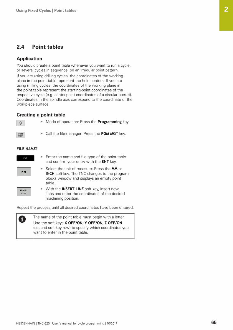
Using Fixed Cycles | Point tables 2
HEIDENHAIN | TNC 620 | User’s manual for cycle programming | 10/2017 65
2.4 Point tables
ApplicationYou should create a point table whenever you want to run a cycle,or several cycles in sequence, on an irregular point pattern.If you are using drilling cycles, the coordinates of the workingplane in the point table represent the hole centers. If you areusing milling cycles, the coordinates of the working plane inthe point table represent the starting-point coordinates of therespective cycle (e.g. center-point coordinates of a circular pocket).Coordinates in the spindle axis correspond to the coordinate of theworkpiece surface.
Creating a point tableMode of operation: Press the Programming key
Call the file manager: Press the PGM MGT key.
FILE NAME?
Enter the name and file type of the point tableand confirm your entry with the ENT key.
Select the unit of measure: Press the MM orINCH soft key. The TNC changes to the programblocks window and displays an empty pointtable.With the INSERT LINE soft key, insert newlines and enter the coordinates of the desiredmachining position.
Repeat the process until all desired coordinates have been entered.
The name of the point table must begin with a letter.Use the soft keys X OFF/ON, Y OFF/ON, Z OFF/ON(second soft-key row) to specify which coordinates youwant to enter in the point table.

Using Fixed Cycles | Point tables 2
66 HEIDENHAIN | TNC 620 | User’s manual for cycle programming | 10/2017
Hiding single points from the machining processIn the FADE column of the point table you can specify if the definedpoint is to be hidden during the machining process.
In the table, select the point to be hidden
Select the FADE column
Activate hiding, or
NOENT
Deactivate hiding
Selecting a point table in the programIn the Programming mode of operation, select the program forwhich you want to activate the point table:
Press the PGM CALL key to call the function forselecting the point table
Press the POINT TABLE soft key
Enter the name of the point table and confirm your entry with theEND key. If the point table is not stored in the same directory as theNC program, you must enter the complete path.
Example NC block
7 SEL PATTERN "TNC:\DIRKT5\NUST35.PNT"
Using Fixed Cycles | Point tables 2
HEIDENHAIN | TNC 620 | User’s manual for cycle programming | 10/2017 67
Calling a cycle in connection with point tables
With CYCL CALL PAT the TNC runs the point table thatyou last defined (even if you defined the point table in aprogram that was nested with CALL PGM).
If you want the TNC to call the last defined fixed cycle at the pointsdefined in a point table, then program the cycle call with CYCLECALL PAT:
To program the cycle call, press the CYCL CALLkeyPress the CYCL CALL PAT soft key to call a pointtableEnter the feed rate at which the TNC is to movefrom point to point (if you make no entry theTNC will move at the last programmed feed rate;FMAX is not valid)If required, enter a miscellaneous function M,then confirm with the END key
The TNC retracts the tool to the clearance height between thestarting points. Depending on which is greater, the TNC uses eitherthe spindle axis coordinate from the cycle call or the value fromcycle parameter Q204 as the clearance height.Before CYCL CALL PAT you can use the function GLOBAL DEF 125(located in SPEC FCT/program defaults) with Q352=1. Then theTNC always retracts the tool between the holes to the 2nd set-upclearance that was defined in the cycle.If you want to move at reduced feed rate when pre-positioning inthe spindle axis, use the miscellaneous function M103.
Effect of the point table with SL cycles and Cycle 12
The TNC interprets the points as an additional datum shift.
Effect of the point table with Cycles 200 to 208 and 262 to 267
The TNC interprets the points of the working plane as coordinatesof the hole centers. If you want to use the coordinate defined inthe point table for the spindle axis as the starting point coordinate,you must define the workpiece surface coordinate (Q203) as 0.
Effect of the point table with Cycles 251 to 254
The TNC interprets the points of the working plane as coordinatesof the cycle starting point. If you want to use the coordinatedefined in the point table for the spindle axis as the starting pointcoordinate, you must define the workpiece surface coordinate(Q203) as 0.


3Fixed Cycles:
Drilling

Fixed Cycles: Drilling | Fundamentals 3
70 HEIDENHAIN | TNC 620 | User’s manual for cycle programming | 10/2017
3.1 Fundamentals
OverviewThe TNC offers the following cycles for all types of drillingoperations:
Soft key Cycle Page
240 CENTERINGWith automatic pre-positioning, 2ndset-up clearance, optional entry of thecentering diameter or centering depth
71
200 DRILLING With automatic pre-positioning, 2ndset-up clearance
73
201 REAMING With automatic pre-positioning, 2ndset-up clearance
75
202 BORING With automatic pre-positioning, 2ndset-up clearance
77
203 UNIVERSAL DRILLING With automatic pre-positioning, 2ndset-up clearance, chip breaking, anddecrementing
80
204 BACK BORING With automatic pre-positioning, 2ndset-up clearance
86
205 UNIVERSAL PECKINGWith automatic pre-positioning, 2ndset-up clearance, chip breaking, andadvanced stop distance
90
208 BORE MILLINGWith automatic pre-positioning, 2ndset-up clearance
98
241 SINGLE-LIP D.H.DRLNG With automatic pre-positioning todeepened starting point, shaft speedand coolant definition
101

Fixed Cycles: Drilling | CENTERING (Cycle 240, DIN/ISO: G240, software option 19) 3
HEIDENHAIN | TNC 620 | User’s manual for cycle programming | 10/2017 71
3.2 CENTERING (Cycle 240, DIN/ISO: G240,software option 19)
Cycle run1 The TNC positions the tool in the tool axis at rapid traverse
FMAX to the set-up clearance above the workpiece surface.2 The tool is centered at the programmed feed rate F to the
programmed centering diameter or centering depth.3 If defined, the tool remains at the centering depth.4 Finally, the tool path is retraced to setup clearance or—if
programmed—to the 2nd setup clearance at rapid traverseFMAX.
Please note while programming:
Program a positioning block for the starting point(hole center) in the working plane with the radiuscompensation R0The algebraic sign for the cycle parameter Q344(diameter) or Q201 (depth) determines the workingdirection. If you program the diameter or depth = 0, thecycle will not be executed.
NOTICEDanger of collision!
If you enter a positive depth with a cycle, the TNC reversescalculation of the pre-positioning. This means that the toolmoves at rapid traverse in the tool axis to set-up clearancebelow the workpiece surface!
Enter depth as negativeEnter in machine parameter displayDepthErr (No. 201003)whether the TNC should output an error message (on) or not(off) if a positive depth is entered

Fixed Cycles: Drilling | CENTERING (Cycle 240, DIN/ISO: G240, software option 19) 3
72 HEIDENHAIN | TNC 620 | User’s manual for cycle programming | 10/2017
Cycle parametersQ200 Set-up clearance? (incremental): Distancebetween tool tip and workpiece surface. Enter apositive value. Input range 0 to 99999.9999Q343 Select diameter/depth (1/0): Selectwhether centering is based on the entereddiameter or entered depth. If the TNC is to centerbased on the entered diameter, the point angle ofthe tool must be defined in the T angle column ofthe tool table TOOL.T. 0: Centering based on the entered depth 1: Centering based on the entered diameterQ201 Depth? (incremental): Distance betweenworkpiece surface and centering bottom (tipof centering taper). Only effective if Q343=0 isdefined. Input range -99999.9999 to 99999.9999Q344 Diameter of counterbore (algebraic sign):Centering diameter. Only effective if Q343=1 isdefined. Input range -99999.9999 to 99999.9999Q206 Feed rate for plunging?: Traversing speedof the tool in mm/min while centering. Input range0 to 99999.999, alternatively FAUTO, fuQ211 Dwell time at the depth?: Time in secondsthat the tool remains at the hole bottom. Inputrange 0 to 3600.0000Q203 Workpiece surface coordinate? (absolute):Coordinate of the workpiece surface. Input range-99999.9999 to 99999.9999Q204 2nd set-up clearance? (incremental):Coordinate in the spindle axis at which no collisionbetween tool and workpiece (fixtures) can occur.Input range 0 to 99999.9999
NC blocks
10 L Z+100 R0 FMAX
11 CYCL DEF 240 CENTERING
Q200=2 ;SET-UP CLEARANCE
Q343=1 ;SELECT DIA./DEPTH
Q201=+0 ;DEPTH
Q344=-9 ;DIAMETER
Q206=250 ;FEED RATE FOR PLNGNG
Q211=0.1 ;DWELL TIME AT DEPTH
Q203=+20 ;SURFACE COORDINATE
Q204=100 ;2ND SET-UP CLEARANCE
12 L X+30 Y+20 R0 FMAX M3 M99
13 L X+80 Y+50 R0 FMAX M99

Fixed Cycles: Drilling | DRILLING (Cycle 200) 3
HEIDENHAIN | TNC 620 | User’s manual for cycle programming | 10/2017 73
3.3 DRILLING (Cycle 200)
Cycle run1 The TNC positions the tool in the tool axis at rapid traverse
FMAX to set-up clearance above the workpiece surface.2 The tool drills to the first plunging depth at the programmed
feed rate F.3 The TNC returns the tool at FMAX to the set-up clearance,
dwells there (if a dwell time was entered), and then moves atFMAX to the set-up clearance above the first plunging depth.
4 The tool then drills deeper by the plunging depth at theprogrammed feed rate F.
5 The TNC repeats this process (2 to 4) until the programmeddepth is reached (the dwell time from Q211 is effective withevery infeed)
6 Finally, the tool path is retraced to setup clearance from thehole bottom or—if programmed—to the 2nd setup clearance atFMAX.
Please note while programming:
Program a positioning block for the starting point (holecenter) in the working plane with radius compensationR0The algebraic sign for the cycle parameter DEPTHdetermines the working direction. If you programDEPTH=0, the cycle will not be executed.
NOTICEDanger of collision!
If you enter a positive depth with a cycle, the TNC reversescalculation of the pre-positioning. This means that the toolmoves at rapid traverse in the tool axis to set-up clearancebelow the workpiece surface!
Enter depth as negativeEnter in machine parameter displayDepthErr (No. 201003)whether the TNC should output an error message (on) or not(off) if a positive depth is entered

Fixed Cycles: Drilling | DRILLING (Cycle 200) 3
74 HEIDENHAIN | TNC 620 | User’s manual for cycle programming | 10/2017
Cycle parametersQ200 Set-up clearance? (incremental): Distancebetween tool tip and workpiece surface. Enter apositive value. Input range 0 to 99999.9999Q201 Depth? (incremental): Distance betweenworkpiece surface and bottom of hole. Input range-99999.9999 to 99999.9999Q206 Feed rate for plunging?: Traversing speedof the tool in mm/min while drilling. Input range 0to 99999.999, alternatively FAUTO, FUQ202 Plunging depth? (incremental): Infeed percut Input range 0 to 99999.9999The depth does not have to be a multiple of theplunging depth. The TNC will go to depth in onemovement if:
the plunging depth is equal to the depththe plunging depth is greater than the depth
Q210 Dwell time at the top?: Time in secondsthat the tool remains at set-up clearance afterhaving been retracted from the hole for chipbreaking. Input range 0 to 3600.0000Q203 Workpiece surface coordinate? (absolute):Coordinate of the workpiece surface. Input range-99999.9999 to 99999.9999Q204 2nd set-up clearance? (incremental):Coordinate in the spindle axis at which no collisionbetween tool and workpiece (fixtures) can occur.Input range 0 to 99999.9999Q211 Dwell time at the depth?: Time in secondsthat the tool remains at the hole bottom. Inputrange 0 to 3600.0000Q395 Diameter as reference (0/1)?: Selectwhether the entered depth is referenced to thetool tip or the cylindrical part of the tool. If the TNCis to reference the depth to the cylindrical partof the tool, the point angle of the tool must bedefined in the T ANGLE column of the tool tableTOOL.T.0 = Depth referenced to the tool tip1 = Depth referenced to the cylindrical part of thetool
NC blocks
11 CYCL DEF 200 DRILLING
Q200=2 ;SET-UP CLEARANCE
Q201=-15 ;DEPTH
Q206=250 ;FEED RATE FOR PLNGNG
Q202=5 ;PLUNGING DEPTH
Q211=0 ;DWELL TIME AT TOP
Q203=+20 ;SURFACE COORDINATE
Q204=100 ;2ND SET-UP CLEARANCE
Q211=0.1 ;DWELL TIME AT DEPTH
Q395=0 ;DEPTH REFERENCE
12 L X+30 Y+20 FMAX M3
13 CYCL CALL
14 L X+80 Y+50 FMAX M99

Fixed Cycles: Drilling | REAMING (Cycle 201, DIN/ISO: G201, software option 19) 3
HEIDENHAIN | TNC 620 | User’s manual for cycle programming | 10/2017 75
3.4 REAMING (Cycle 201, DIN/ISO: G201,software option 19)
Cycle run1 The TNC positions the tool in the tool axis at rapid traverse
FMAX to the entered set-up clearance above the workpiecesurface.
2 The tool reams to the entered depth at the programmed feedrate F.
3 If programmed, the tool remains at the hole bottom for theentered dwell time.
4 The tool then retracts to set-up clearance at the feed rate F, andfrom there—if programmed—to the 2nd set-up clearance inFMAX.
Please note while programming:
Program a positioning block for the starting point (holecenter) in the working plane with radius compensationR0.The algebraic sign for the cycle parameter DEPTHdetermines the working direction. If you programDEPTH=0, the cycle will not be executed.
NOTICEDanger of collision!
If you enter a positive depth with a cycle, the TNC reversescalculation of the pre-positioning. This means that the toolmoves at rapid traverse in the tool axis to set-up clearancebelow the workpiece surface!
Enter depth as negativeEnter in machine parameter displayDepthErr (No. 201003)whether the TNC should output an error message (on) or not(off) if a positive depth is entered

Fixed Cycles: Drilling | REAMING (Cycle 201, DIN/ISO: G201, software option 19) 3
76 HEIDENHAIN | TNC 620 | User’s manual for cycle programming | 10/2017
Cycle parametersQ200 Set-up clearance? (incremental): Distancebetween tool tip and workpiece surface. Inputrange 0 to 99999.9999Q201 Depth? (incremental): Distance betweenworkpiece surface and bottom of hole. Input range-99999.9999 to 99999.9999Q206 Feed rate for plunging?: Traversing speedof the tool in mm/min while reaming. Input range0 to 99999.999, alternatively FAUTO, fuQ211 Dwell time at the depth?: Time in secondsthat the tool remains at the hole bottom. Inputrange 0 to 3600.0000Q208 Feed rate for retraction?: Traverse speedof tool when moving out of the hole in mm/min.If you enter Q208 = 0, the feed rate for reamingapplies. Input range 0 to 99999.999Q203 Workpiece surface coordinate? (absolute):Coordinate of the workpiece surface. Input range 0to 99999.9999Q204 2nd set-up clearance? (incremental):Coordinate in the spindle axis at which no collisionbetween tool and workpiece (fixtures) can occur.Input range 0 to 99999.9999
NC blocks
11 CYCL DEF 201 REAMING
Q200=2 ;SET-UP CLEARANCE
Q201=-15 ;DEPTH
Q206=100 ;FEED RATE FOR PLNGNG
Q211=0.5 ;DWELL TIME AT DEPTH
Q208=250 ;RETRACTION FEED RATE
Q203=+20 ;SURFACE COORDINATE
Q204=100 ;2ND SET-UP CLEARANCE
12 L X+30 Y+20 FMAX M3
13 CYCL CALL
14 L X+80 Y+50 FMAX M9
15 L Z+100 FMAX M2

Fixed Cycles: Drilling | BORING (Cycle 202, DIN/ISO: G202, software option 19) 3
HEIDENHAIN | TNC 620 | User’s manual for cycle programming | 10/2017 77
3.5 BORING (Cycle 202, DIN/ISO: G202,software option 19)
Cycle run1 The TNC positions the tool in the tool axis at rapid traverse
FMAX to set-up clearance above the workpiece surface.2 The tool drills to the programmed depth at the feed rate for
plunging.3 If programmed, the tool remains at the hole bottom for the
entered dwell time with active spindle rotation for cutting free.4 The TNC then orients the spindle to the position that is defined
in parameter Q336.5 If retraction is selected, the tool retracts in the programmed
direction by 0.2 mm (fixed value).6 The tool then retracts to set-up clearance at the retraction rate,
and from there—if programmed—to the 2nd set-up clearance atFMAX. If Q214=0 the tool point remains on the wall of the hole.
7 The TNC finally positions the tool back at the center of the hole.

Fixed Cycles: Drilling | BORING (Cycle 202, DIN/ISO: G202, software option 19) 3
78 HEIDENHAIN | TNC 620 | User’s manual for cycle programming | 10/2017
Please note while programming:
Machine and TNC must be specially prepared by themachine tool builder for use of this cycle.This cycle is effective only for machines with servo-controlled spindle.
Program a positioning block for the starting point (holecenter) in the working plane with radius compensationR0.The algebraic sign for the cycle parameter DEPTHdetermines the working direction. If you programDEPTH=0, the cycle will not be executed.After machining, the TNC positions the tool back at thestarting point of the machining plane. This way, you cancontinue positioning incrementally.If the functions M7 or M8 were active before calling thecycle, the TNC will reconstruct this previous state at theend of the cycle.
NOTICEDanger of collision!
If you enter a positive depth with a cycle, the TNC reversescalculation of the pre-positioning. This means that the toolmoves at rapid traverse in the tool axis to set-up clearancebelow the workpiece surface!
Enter depth as negativeEnter in machine parameter displayDepthErr (No. 201003)whether the TNC should output an error message (on) or not(off) if a positive depth is entered
NOTICEDanger of collision!
There is a danger of collision if you select the disengagingdirection incorrectly. Any existing mirroring in the work plane isnot taken into account for the disengaging direction. However,active transformations are considered with disengaging.
Check the position of the tool tip when you program aspindle orientation to the angle that you enter in Q336 (forexample, in the Positioning with Manual Data Input modeof operation). No transformations should be active here.Select the angle so that the tool tip is parallel to thedisengaging directionSelect the disengaging direction Q214 so that the tool movesaway from the edge of the hole
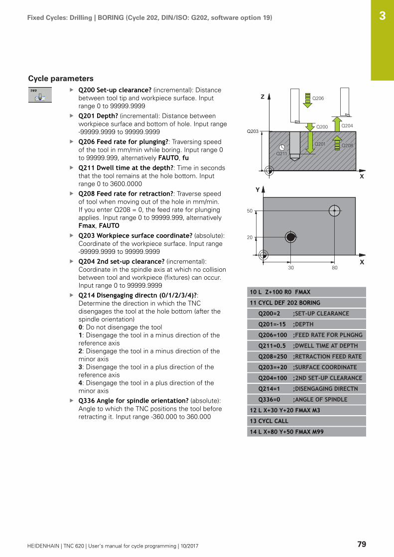
Fixed Cycles: Drilling | BORING (Cycle 202, DIN/ISO: G202, software option 19) 3
HEIDENHAIN | TNC 620 | User’s manual for cycle programming | 10/2017 79
Cycle parametersQ200 Set-up clearance? (incremental): Distancebetween tool tip and workpiece surface. Inputrange 0 to 99999.9999Q201 Depth? (incremental): Distance betweenworkpiece surface and bottom of hole. Input range-99999.9999 to 99999.9999Q206 Feed rate for plunging?: Traversing speedof the tool in mm/min while boring. Input range 0to 99999.999, alternatively FAUTO, fuQ211 Dwell time at the depth?: Time in secondsthat the tool remains at the hole bottom. Inputrange 0 to 3600.0000Q208 Feed rate for retraction?: Traverse speedof tool when moving out of the hole in mm/min.If you enter Q208 = 0, the feed rate for plungingapplies. Input range 0 to 99999.999, alternativelyFmax, FAUTOQ203 Workpiece surface coordinate? (absolute):Coordinate of the workpiece surface. Input range-99999.9999 to 99999.9999Q204 2nd set-up clearance? (incremental):Coordinate in the spindle axis at which no collisionbetween tool and workpiece (fixtures) can occur.Input range 0 to 99999.9999Q214 Disengaging directn (0/1/2/3/4)?:Determine the direction in which the TNCdisengages the tool at the hole bottom (after thespindle orientation) 0: Do not disengage the tool1: Disengage the tool in a minus direction of thereference axis2: Disengage the tool in a minus direction of theminor axis3: Disengage the tool in a plus direction of thereference axis4: Disengage the tool in a plus direction of theminor axisQ336 Angle for spindle orientation? (absolute):Angle to which the TNC positions the tool beforeretracting it. Input range -360.000 to 360.000
10 L Z+100 R0 FMAX
11 CYCL DEF 202 BORING
Q200=2 ;SET-UP CLEARANCE
Q201=-15 ;DEPTH
Q206=100 ;FEED RATE FOR PLNGNG
Q211=0.5 ;DWELL TIME AT DEPTH
Q208=250 ;RETRACTION FEED RATE
Q203=+20 ;SURFACE COORDINATE
Q204=100 ;2ND SET-UP CLEARANCE
Q214=1 ;DISENGAGING DIRECTN
Q336=0 ;ANGLE OF SPINDLE
12 L X+30 Y+20 FMAX M3
13 CYCL CALL
14 L X+80 Y+50 FMAX M99

Fixed Cycles: Drilling | UNIVERSAL DRILLING (Cycle 203, DIN/ISO: G203, software option 19) 3
80 HEIDENHAIN | TNC 620 | User’s manual for cycle programming | 10/2017
3.6 UNIVERSAL DRILLING (Cycle 203, DIN/ISO: G203, software option 19)
Cycle runBehavior without chip breaking and without decrement:
1 The TNC positions the tool in the spindle axis at rapid traverseFMAX to the programmed SET-UP CLEARANCEQ200 above theworkpiece surface
2 The tool drills at the programmed FEED RATE FORPLNGNGQ206 to the first PLUNGING DEPTHQ202
3 Then the TNC removes the tool from the hole to SET-UPCLEARANCEQ200
4 The TNC now again plunges the tool at rapid traverse into thehole and then again drills an infeed of PLUNGING DEPTHQ202FEED RATE FOR PLNGNGQ206
5 When machining without chip breakage the TNC removes thetool from the hole after each infeed with RETRACTION FEEDRATEQ208 to SET-UP CLEARANCEQ200 and remains there forthe DWELL TIME AT TOPQ210.
6 This procedure is repeated until depth Q201 is achieved.7 When depth Q201 is achieved, the TNC removes the tool with
Fmax from the hole to the 2nd set-up clearance Q204
Fixed Cycles: Drilling | UNIVERSAL DRILLING (Cycle 203, DIN/ISO: G203, software option 19) 3
HEIDENHAIN | TNC 620 | User’s manual for cycle programming | 10/2017 81
Behavior with chip breaking and without decrement:
1 The TNC positions the tool in the tool axis at rapid traverseFMAX to the entered set-up clearance above the workpiecesurface.
2 The tool drills at the programmed feed rate for plunging Q206to the first plunging depth Q202
3 The TNC then disengages the tool by the value of Retractionrate for chip breaking Q256
4 An infeed is then again machined by the value of plungingdepth Q202 at feed rate for plunging Q206
5 The TNC repeatedly infeeds until achieving the number of chipbreaks Q213 or until the hole has the desired depth Q201.If the defined number of chip breaks is achieved but the holedoes not yet have the desired depth Q201, the TNC retracts thetool from the hole at feed rate for retraction Q208 to set-upclearance Q200
6 If programmed, the TNC now waits in accordance with thedwell time at top Q210
7 Then the TNC plunges at rapid traverse into the hole to thevalue retraction rate for chip breaking Q256 above the lastinfeed depth
8 Procedure 2-7 is repeated until depth Q201 is achieved.9 When Depth Q201 is achieved, the TNC removes the tool with
Fmax from the hole to the 2nd set-up clearance Q204
Fixed Cycles: Drilling | UNIVERSAL DRILLING (Cycle 203, DIN/ISO: G203, software option 19) 3
82 HEIDENHAIN | TNC 620 | User’s manual for cycle programming | 10/2017
Behavior with chip breaking and with decrement
1 The TNC positions the tool in the spindle axis at rapid traverseFMAX to the programmed set-up clearance above the workpiecesurface
2 The tool drills at the programmed feed rate for plunging Q206to the first plunging depth Q202
3 The TNC then disengages the tool by the value of Retractionrate for chip breaking Q256
4 An infeed is then again machined by the value of plungingdepth Q202 minus decrement Q212 at feed rate for plungingQ206. The continuously declining difference from the updatedplunging depth Q202 minus decrement Q212 must neverbe less than the minimum plunging depth Q205 (example:Q202=5, Q212=1, Q213=4, Q205= 3: The first plunging depthis 5 mm, the second plunging depth is 5 - 1 = 4 mm, the thirdplunging depth is 4 - 1 = 3 mm and the fourth plunging depth isalso 3 mm)
5 The TNC repeatedly infeeds until achieving the number of chipbreaks Q213 or until the hole has the desired depth Q201.If the defined number of chip breaks is achieved but the holedoes not yet have the desired depth Q201, the TNC retracts thetool from the hole at feed rate for retraction Q208 to set-upclearance Q200
6 If programmed, the TNC now waits in accordance with thedwell time at top Q210
7 Then the TNC plunges at rapid traverse into the hole to thevalue retraction rate for chip breaking Q256 above the lastinfeed depth
8 Procedure 2-7 is repeated until depth Q201 is achieved.9 If programmed, the TNC now waits in accordance with the
dwell time at depth Q21110 When Depth Q201 is achieved and dwell time at depth Q211
has expired, the TNC removes the tool with Fmax from the holeto the 2nd set-up clearance Q204
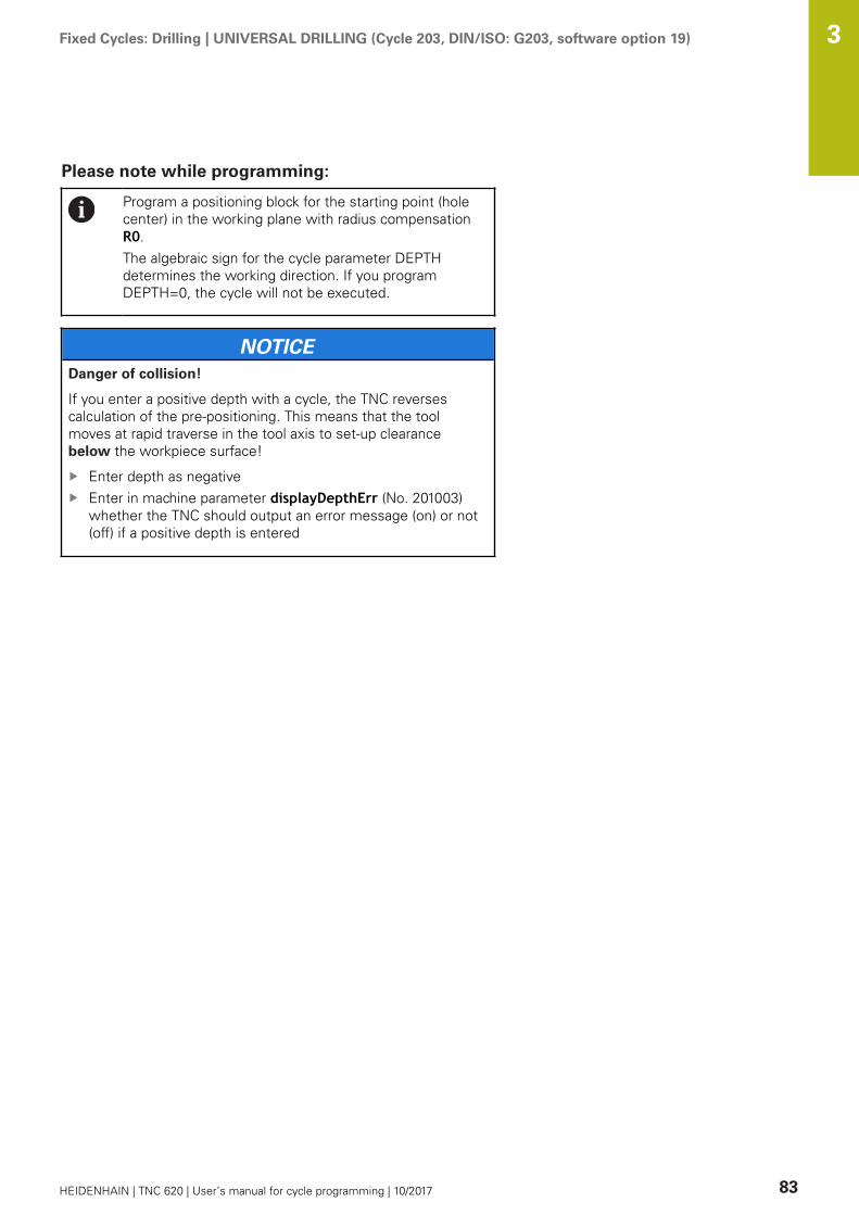
Fixed Cycles: Drilling | UNIVERSAL DRILLING (Cycle 203, DIN/ISO: G203, software option 19) 3
HEIDENHAIN | TNC 620 | User’s manual for cycle programming | 10/2017 83
Please note while programming:
Program a positioning block for the starting point (holecenter) in the working plane with radius compensationR0.The algebraic sign for the cycle parameter DEPTHdetermines the working direction. If you programDEPTH=0, the cycle will not be executed.
NOTICEDanger of collision!
If you enter a positive depth with a cycle, the TNC reversescalculation of the pre-positioning. This means that the toolmoves at rapid traverse in the tool axis to set-up clearancebelow the workpiece surface!
Enter depth as negativeEnter in machine parameter displayDepthErr (No. 201003)whether the TNC should output an error message (on) or not(off) if a positive depth is entered
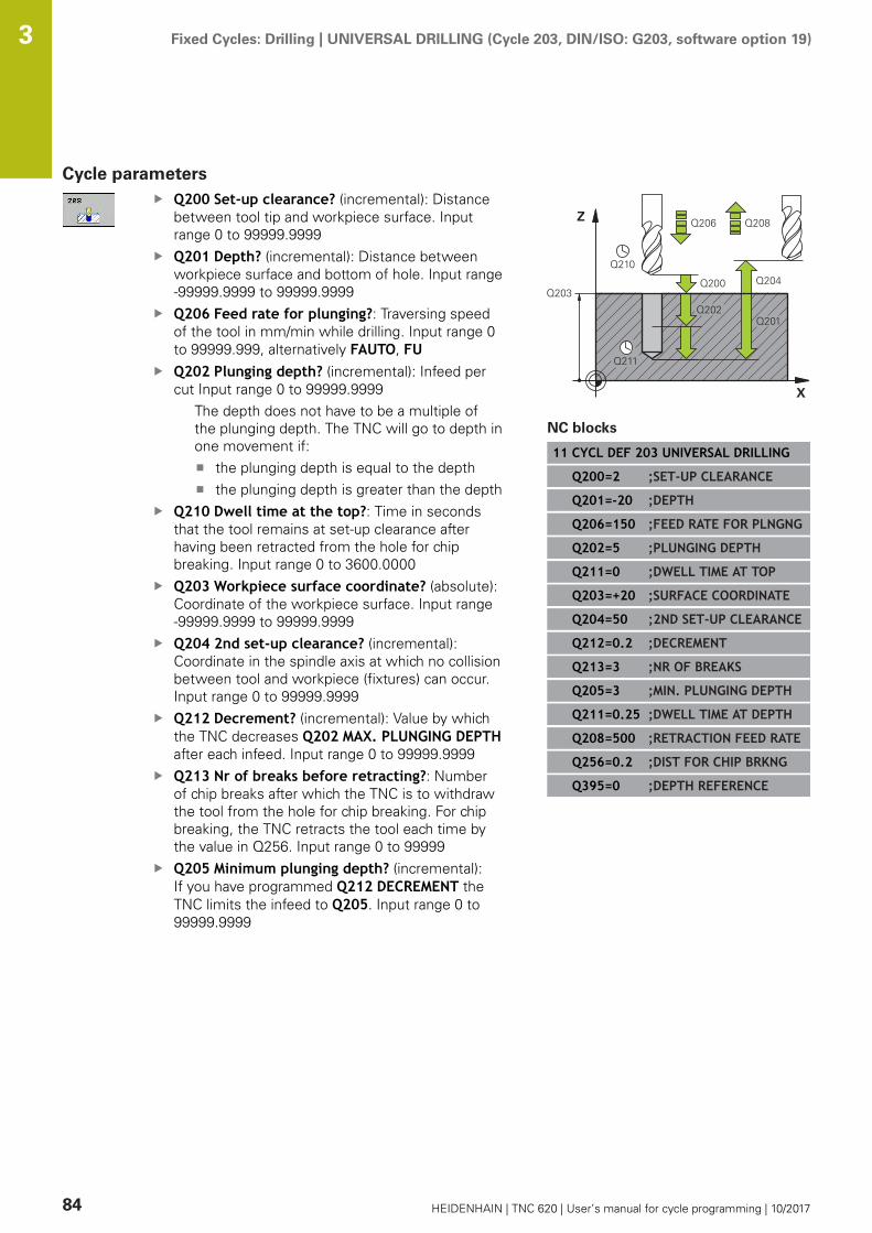
Fixed Cycles: Drilling | UNIVERSAL DRILLING (Cycle 203, DIN/ISO: G203, software option 19) 3
84 HEIDENHAIN | TNC 620 | User’s manual for cycle programming | 10/2017
Cycle parametersQ200 Set-up clearance? (incremental): Distancebetween tool tip and workpiece surface. Inputrange 0 to 99999.9999Q201 Depth? (incremental): Distance betweenworkpiece surface and bottom of hole. Input range-99999.9999 to 99999.9999Q206 Feed rate for plunging?: Traversing speedof the tool in mm/min while drilling. Input range 0to 99999.999, alternatively FAUTO, FUQ202 Plunging depth? (incremental): Infeed percut Input range 0 to 99999.9999
The depth does not have to be a multiple ofthe plunging depth. The TNC will go to depth inone movement if:
the plunging depth is equal to the depththe plunging depth is greater than the depth
Q210 Dwell time at the top?: Time in secondsthat the tool remains at set-up clearance afterhaving been retracted from the hole for chipbreaking. Input range 0 to 3600.0000Q203 Workpiece surface coordinate? (absolute):Coordinate of the workpiece surface. Input range-99999.9999 to 99999.9999Q204 2nd set-up clearance? (incremental):Coordinate in the spindle axis at which no collisionbetween tool and workpiece (fixtures) can occur.Input range 0 to 99999.9999Q212 Decrement? (incremental): Value by whichthe TNC decreases Q202 MAX. PLUNGING DEPTHafter each infeed. Input range 0 to 99999.9999Q213 Nr of breaks before retracting?: Numberof chip breaks after which the TNC is to withdrawthe tool from the hole for chip breaking. For chipbreaking, the TNC retracts the tool each time bythe value in Q256. Input range 0 to 99999Q205 Minimum plunging depth? (incremental):If you have programmed Q212 DECREMENT theTNC limits the infeed to Q205. Input range 0 to99999.9999
NC blocks
11 CYCL DEF 203 UNIVERSAL DRILLING
Q200=2 ;SET-UP CLEARANCE
Q201=-20 ;DEPTH
Q206=150 ;FEED RATE FOR PLNGNG
Q202=5 ;PLUNGING DEPTH
Q211=0 ;DWELL TIME AT TOP
Q203=+20 ;SURFACE COORDINATE
Q204=50 ;2ND SET-UP CLEARANCE
Q212=0.2 ;DECREMENT
Q213=3 ;NR OF BREAKS
Q205=3 ;MIN. PLUNGING DEPTH
Q211=0.25 ;DWELL TIME AT DEPTH
Q208=500 ;RETRACTION FEED RATE
Q256=0.2 ;DIST FOR CHIP BRKNG
Q395=0 ;DEPTH REFERENCE

Fixed Cycles: Drilling | UNIVERSAL DRILLING (Cycle 203, DIN/ISO: G203, software option 19) 3
HEIDENHAIN | TNC 620 | User’s manual for cycle programming | 10/2017 85
Q211 Dwell time at the depth?: Time in secondsthat the tool remains at the hole bottom. Inputrange 0 to 3600.0000Q208 Feed rate for retraction?: Traverse speedof tool when moving out of the hole in mm/min. Ifyou enter Q208 = 0, the TNC retracts the tool atthe feed rate Q206. Input range 0 to 99999.999,alternatively Fmax, FAUTOQ256 Retract dist. for chip breaking?(incremental): Value by which the TNC retractsthe tool during chip breaking. Input range 0.000 to99999.999Q395 Diameter as reference (0/1)?: Selectwhether the entered depth is referenced to thetool tip or the cylindrical part of the tool. If the TNCis to reference the depth to the cylindrical partof the tool, the point angle of the tool must bedefined in the T ANGLE column of the tool tableTOOL.T.0 = Depth referenced to the tool tip1 = Depth referenced to the cylindrical part of thetool
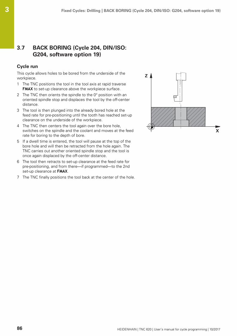
Fixed Cycles: Drilling | BACK BORING (Cycle 204, DIN/ISO: G204, software option 19) 3
86 HEIDENHAIN | TNC 620 | User’s manual for cycle programming | 10/2017
3.7 BACK BORING (Cycle 204, DIN/ISO:G204, software option 19)
Cycle runThis cycle allows holes to be bored from the underside of theworkpiece.1 The TNC positions the tool in the tool axis at rapid traverse
FMAX to set-up clearance above the workpiece surface.2 The TNC then orients the spindle to the 0° position with an
oriented spindle stop and displaces the tool by the off-centerdistance.
3 The tool is then plunged into the already bored hole at thefeed rate for pre-positioning until the tooth has reached set-upclearance on the underside of the workpiece.
4 The TNC then centers the tool again over the bore hole,switches on the spindle and the coolant and moves at the feedrate for boring to the depth of bore.
5 If a dwell time is entered, the tool will pause at the top of thebore hole and will then be retracted from the hole again. TheTNC carries out another oriented spindle stop and the tool isonce again displaced by the off-center distance.
6 The tool then retracts to set-up clearance at the feed rate forpre-positioning, and from there—if programmed—to the 2ndset-up clearance at FMAX.
7 The TNC finally positions the tool back at the center of the hole.

Fixed Cycles: Drilling | BACK BORING (Cycle 204, DIN/ISO: G204, software option 19) 3
HEIDENHAIN | TNC 620 | User’s manual for cycle programming | 10/2017 87
Please note while programming:
Machine and TNC must be specially prepared by themachine tool builder for use of this cycle.This cycle is effective only for machines with servo-controlled spindle.Special boring bars for upward cutting are required forthis cycle.
Program a positioning block for the starting point (holecenter) in the working plane with radius compensationR0.After machining, the TNC positions the tool back at thestarting point of the machining plane. This way, you cancontinue positioning incrementally.The algebraic sign for the cycle parameter depthdetermines the working direction. Note: A positive signbores in the direction of the positive spindle axis.Enter the tool length so that the underside of the boringbar is measured and not the tool tip.When calculating the starting point for boring, the TNCconsiders the tooth length of the boring bar and thethickness of the material.If the functions M7 or M8 were active before calling thecycle, the TNC will reconstruct this previous state at theend of the cycle.
NOTICEDanger of collision!
There is a danger of collision if you select the disengagingdirection incorrectly. Any existing mirroring in the work plane isnot taken into account for the disengaging direction. However,active transformations are considered with disengaging.
Check the position of the tool tip when you program aspindle orientation to the angle that you enter in Q336 (forexample, in the Positioning with Manual Data Input modeof operation). No transformations should be active here.Select the angle so that the tool tip is parallel to thedisengaging directionSelect the disengaging direction Q214 so that the tool movesaway from the edge of the hole
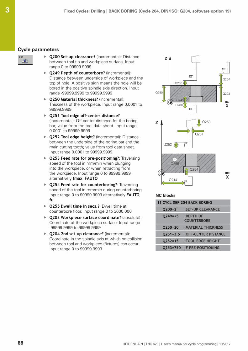
Fixed Cycles: Drilling | BACK BORING (Cycle 204, DIN/ISO: G204, software option 19) 3
88 HEIDENHAIN | TNC 620 | User’s manual for cycle programming | 10/2017
Cycle parametersQ200 Set-up clearance? (incremental): Distancebetween tool tip and workpiece surface. Inputrange 0 to 99999.9999Q249 Depth of counterbore? (incremental):Distance between underside of workpiece and thetop of hole. A positive sign means the hole will bebored in the positive spindle axis direction. Inputrange -99999.9999 to 99999.9999Q250 Material thickness? (incremental):Thickness of the workpiece. Input range 0.0001 to99999.9999Q251 Tool edge off-center distance?(incremental): Off-center distance for the boringbar; value from the tool data sheet. Input range0.0001 to 99999.9999Q252 Tool edge height? (incremental): Distancebetween the underside of the boring bar and themain cutting tooth; value from tool data sheet.Input range 0.0001 to 99999.9999Q253 Feed rate for pre-positioning?: Traversingspeed of the tool in mm/min when plunginginto the workpiece, or when retracting fromthe workpiece. Input range 0 to 99999.9999alternatively fmax, FAUTOQ254 Feed rate for counterboring?: Traversingspeed of the tool in mm/min during counterboring.Input range 0 to 99999.9999 alternatively FAUTO,fuQ255 Dwell time in secs.?: Dwell time atcounterbore floor. Input range 0 to 3600.000Q203 Workpiece surface coordinate? (absolute):Coordinate of the workpiece surface. Input range-99999.9999 to 99999.9999Q204 2nd set-up clearance? (incremental):Coordinate in the spindle axis at which no collisionbetween tool and workpiece (fixtures) can occur.Input range 0 to 99999.9999
NC blocks
11 CYCL DEF 204 BACK BORING
Q200=2 ;SET-UP CLEARANCE
Q249=+5 ;DEPTH OFCOUNTERBORE
Q250=20 ;MATERIAL THICKNESS
Q251=3.5 ;OFF-CENTER DISTANCE
Q252=15 ;TOOL EDGE HEIGHT
Q253=750 ;F PRE-POSITIONING
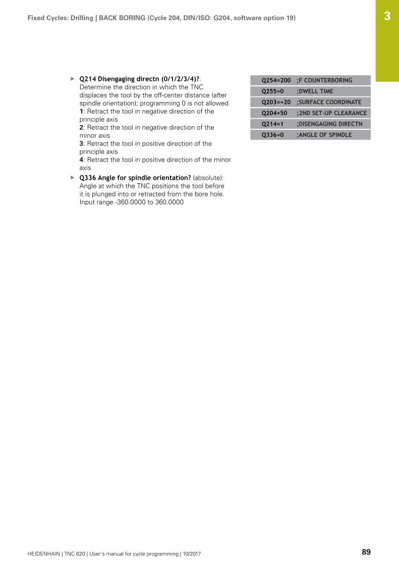
Fixed Cycles: Drilling | BACK BORING (Cycle 204, DIN/ISO: G204, software option 19) 3
HEIDENHAIN | TNC 620 | User’s manual for cycle programming | 10/2017 89
Q214 Disengaging directn (0/1/2/3/4)?:Determine the direction in which the TNCdisplaces the tool by the off-center distance (afterspindle orientation); programming 0 is not allowed1: Retract the tool in negative direction of theprinciple axis2: Retract the tool in negative direction of theminor axis3: Retract the tool in positive direction of theprinciple axis4: Retract the tool in positive direction of the minoraxisQ336 Angle for spindle orientation? (absolute):Angle at which the TNC positions the tool beforeit is plunged into or retracted from the bore hole.Input range -360.0000 to 360.0000
Q254=200 ;F COUNTERBORING
Q255=0 ;DWELL TIME
Q203=+20 ;SURFACE COORDINATE
Q204=50 ;2ND SET-UP CLEARANCE
Q214=1 ;DISENGAGING DIRECTN
Q336=0 ;ANGLE OF SPINDLE
Fixed Cycles: Drilling | UNIVERSAL PECKING (Cycle 205, DIN/ISO: G205, software option 19) 3
90 HEIDENHAIN | TNC 620 | User’s manual for cycle programming | 10/2017
3.8 UNIVERSAL PECKING (Cycle 205, DIN/ISO: G205, software option 19)
Cycle run1 The TNC positions the tool in the tool axis at rapid traverse
FMAX to the entered set-up clearance above the workpiecesurface.
2 If you enter a deepened starting point, the TNC move at thedefined positioning feed rate to the set-up clearance above thedeepened starting point.
3 The tool drills to the first plunging depth at the entered feed rateF.
4 If you have programmed chip breaking, the tool then retractsby the entered retraction value. If you are working withoutchip breaking, the tool is moved at rapid traverse to the set-upclearance, and then at FMAX to the entered starting positionabove the first plunging depth.
5 The tool then advances with another infeed at the programmedfeed rate. If programmed, the plunging depth is decreased aftereach infeed by the decrement.
6 The TNC repeats this process (2 to 4) until the programmedtotal hole depth is reached.
7 The tool remains at the hole bottom—if programmed—forthe entered dwell time to cut free, and then retracts to set-upclearance at the retraction feed rate. If programmed, the toolmoves to the 2nd set-up clearance at FMAX.
Fixed Cycles: Drilling | UNIVERSAL PECKING (Cycle 205, DIN/ISO: G205, software option 19) 3
HEIDENHAIN | TNC 620 | User’s manual for cycle programming | 10/2017 91
Please note while programming:
Program a positioning block for the starting point (holecenter) in the working plane with radius compensationR0.The algebraic sign for the cycle parameter DEPTHdetermines the working direction. If you programDEPTH=0, the cycle will not be executed.If you enter different advance stop distances for Q258and Q259, the TNC will change the advance stopdistances between the first and last plunging depths atthe same rate.If you use Q379 to enter a deepened starting point,the TNC merely changes the starting point of theinfeed movement. The TNC does not change retractingmovements; the are referenced to the coordinate of theworkpiece surface.
NOTICEDanger of collision!
If you enter a positive depth with a cycle, the TNC reversescalculation of the pre-positioning. This means that the toolmoves at rapid traverse in the tool axis to set-up clearancebelow the workpiece surface!
Enter depth as negativeEnter in machine parameter displayDepthErr (No. 201003)whether the TNC should output an error message (on) or not(off) if a positive depth is entered
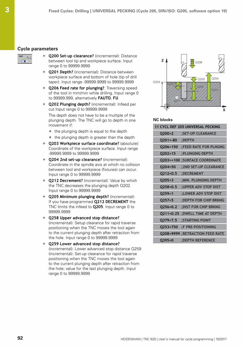
Fixed Cycles: Drilling | UNIVERSAL PECKING (Cycle 205, DIN/ISO: G205, software option 19) 3
92 HEIDENHAIN | TNC 620 | User’s manual for cycle programming | 10/2017
Cycle parametersQ200 Set-up clearance? (incremental): Distancebetween tool tip and workpiece surface. Inputrange 0 to 99999.9999Q201 Depth? (incremental): Distance betweenworkpiece surface and bottom of hole (tip of drilltaper). Input range -99999.9999 to 99999.9999Q206 Feed rate for plunging?: Traversing speedof the tool in mm/min while drilling. Input range 0to 99999.999, alternatively FAUTO, FUQ202 Plunging depth? (incremental): Infeed percut Input range 0 to 99999.9999The depth does not have to be a multiple of theplunging depth. The TNC will go to depth in onemovement if:
the plunging depth is equal to the depththe plunging depth is greater than the depth
Q203 Workpiece surface coordinate? (absolute):Coordinate of the workpiece surface. Input range-99999.9999 to 99999.9999Q204 2nd set-up clearance? (incremental):Coordinate in the spindle axis at which no collisionbetween tool and workpiece (fixtures) can occur.Input range 0 to 99999.9999Q212 Decrement? (incremental): Value by whichthe TNC decreases the plunging depth Q202.Input range 0 to 99999.9999Q205 Minimum plunging depth? (incremental):If you have programmed Q212 DECREMENT theTNC limits the infeed to Q205. Input range 0 to99999.9999Q258 Upper advanced stop distance?(incremental): Setup clearance for rapid traversepositioning when the TNC moves the tool againto the current plunging depth after retraction fromthe hole. Input range 0 to 99999.9999Q259 Lower advanced stop distance?(incremental): Lower advanced stop distance Q259(incremental): Set-up clearance for rapid traversepositioning when the TNC moves the tool againto the current plunging depth after retraction fromthe hole; value for the last plunging depth. Inputrange 0 to 99999.9999
NC blocks
11 CYCL DEF 205 UNIVERSAL PECKING
Q200=2 ;SET-UP CLEARANCE
Q201=-80 ;DEPTH
Q206=150 ;FEED RATE FOR PLNGNG
Q202=15 ;PLUNGING DEPTH
Q203=+100 ;SURFACE COORDINATE
Q204=50 ;2ND SET-UP CLEARANCE
Q212=0.5 ;DECREMENT
Q205=3 ;MIN. PLUNGING DEPTH
Q258=0.5 ;UPPER ADV STOP DIST
Q259=1 ;LOWER ADV STOP DIST
Q257=5 ;DEPTH FOR CHIP BRKNG
Q256=0.2 ;DIST FOR CHIP BRKNG
Q211=0.25 ;DWELL TIME AT DEPTH
Q379=7.5 ;STARTING POINT
Q253=750 ;F PRE-POSITIONING
Q208=9999 ;RETRACTION FEED RATE
Q395=0 ;DEPTH REFERENCE

Fixed Cycles: Drilling | UNIVERSAL PECKING (Cycle 205, DIN/ISO: G205, software option 19) 3
HEIDENHAIN | TNC 620 | User’s manual for cycle programming | 10/2017 93
Q257 Infeed depth for chip breaking?(incremental): Plunging depth after which the TNCbreaks the chip. No chip breaking if 0 is entered.Input range 0 to 99999.9999Q256 Retract dist. for chip breaking?(incremental): Value by which the TNC retractsthe tool during chip breaking. Input range 0.000 to99999.999Q211 Dwell time at the depth?: Time in secondsthat the tool remains at the hole bottom. Inputrange 0 to 3600.0000Q379 Deepened starting point? (incrementalwith respect to Q203 SURFACE COORDINATE,takes Q200 into account): Starting positionof actual drilling. The TNC moves at Q253 FPRE-POSITIONING to the value Q200 SET-UPCLEARANCE above the deepened starting point.Input range 0 to 99999.9999Q253 Feed rate for pre-positioning?: Definesthe traversing speed of the tool when returning toQ201 DEPTH after Q256 DIST FOR CHIP BRKNG.This feed rate is also in effect when the tool ispositioned to Q379 STARTING POINT (not equal0). Entry in mm/min. Input range 0 to 99999.9999alternatively fmax, FAUTOQ208 Feed rate for retraction?: Traversing speedof the tool in mm/min when retracting after themachining operation. If you enter Q208 = 0, theTNC retracts the tool at the feed rate Q206. Inputrange 0 to 99999.9999, alternatively fmax,FAUTOQ395 Diameter as reference (0/1)?: Selectwhether the entered depth is referenced to thetool tip or the cylindrical part of the tool. If the TNCis to reference the depth to the cylindrical partof the tool, the point angle of the tool must bedefined in the T ANGLE column of the tool tableTOOL.T.0 = Depth referenced to the tool tip1 = Depth referenced to the cylindrical part of thetool
Fixed Cycles: Drilling | UNIVERSAL PECKING (Cycle 205, DIN/ISO: G205, software option 19) 3
94 HEIDENHAIN | TNC 620 | User’s manual for cycle programming | 10/2017
Position behavior when working with Q379Several aspects must be observed when working with very longdrilling tools, e.g. single-lip deep hole drills or extra-long twist drills.The position at which the spindle is switched on is decisive. Withextra-long drills, tool breakage may occur if the tool is not guided.For this reason it is recommended to use the parameter STARTINGPOINT Q379. This parameter enables you to influence the positionat which the TNC activates the spindle.Start of drilling
The parameter STARTING POINT Q379 takes into account SURFACECOORDINATE Q203 and the parameter SET-UP CLEARANCE Q200.The following example demonstrates the relationship between theparameters and how the start position is calculated:STARTING POINT Q379=0
The TNC activates the spindle to SET-UP CLEARANCE Q200 viaSURFACE COORDINATE Q203.
STARTING POINT Q379>0The start of drilling is at a specific value above the deepenedstarting point Q379. This value is calculated as follows:0.2 x Q379 If the result of this calculation is greater than Q200the value is always Q200.Example:SURFACE COORDINATE Q203 =0SET-UP CLEARANCE Q200 =2STARTING POINT Q379 =2The start of drilling is calculated as follows:0.2 x Q379=0.2*2=0.4; start of drilling is 0.4 mm/inch above thedeepened starting point. Thus if the deepened starting point isat -2 the TNC initiates the drilling process at -1.6 mm.The following table shows various examples for calculating thestart of drilling:

Fixed Cycles: Drilling | UNIVERSAL PECKING (Cycle 205, DIN/ISO: G205, software option 19) 3
HEIDENHAIN | TNC 620 | User’s manual for cycle programming | 10/2017 95
Start of drilling at deepened starting point
Q200 Q379 Q203 Position at whichpre-positioning isexecuted with FMAX
Factor 0.2 * Q379 Start of drilling
2 2 0 2 0.2*2=0.4 -1.6
2 5 0 2 0.2*5=1 -4
2 10 0 2 0.2*10=2 -8
2 25 0 2 0.2*25=5 (Q200=2, 5>2, thusthe value 2 is used.)
-23
2 100 0 2 0.2*100=20 (Q200=2, 20>2,thus the value 2 is used.)
-98
5 2 0 5 0.2*2=0.4 -1.6
5 5 0 5 0.2*5=1 -4
5 10 0 5 0.2*10=2 -8
5 25 0 5 0.2*25=5 -20
5 100 0 5 0.2*100=20 (Q200=5, 20>5,thus the value 5 is used.)
-95
20 2 0 20 0.2*2=0.4 -1.6
20 5 0 20 0.2*5=1 -4
20 10 0 20 0.2*10=2 -8
20 25 0 20 0.2*25=5 -20
20 100 0 20 0.2*100=20 -80

Fixed Cycles: Drilling | UNIVERSAL PECKING (Cycle 205, DIN/ISO: G205, software option 19) 3
96 HEIDENHAIN | TNC 620 | User’s manual for cycle programming | 10/2017
Chip breaking
The point at which the TNC breaks the chip is also decisive whenworking with extra-long tools. The retraction position with chipbreaking does not have to be at the position at which drilling isstarted. A defined position for chip breakage can ensure that thedrill tool remains in the guide.STARTING POINT Q379=0
Chip breaking is performed at SET-UP CLEARANCE Q200 abovethe SURFACE COORDINATE Q203.
STARTING POINT Q379>0Chip breaking is performed at a specific value above thedeepened starting point Q379. This value is calculated asfollows: 0.8 x Q379 If the result of this calculation is greaterthan Q200 the value is always Q200.Example:SURFACE COORDINATE Q203 =0SET-UP CLEARANCEQ200 =2STARTING POINT Q379 =2The position for chip breaking is calculated as follows:0.8 x Q379=0.8*2=1.6; the position for chip breaking is 1.6 mm/inch above the deepened starting point. Thus if the deepenedstarting point is at -2 the TNC traverses for chip breaking to-0.4 mm.The following table shows various examples for calculating theposition for chip breaking (retraction position):
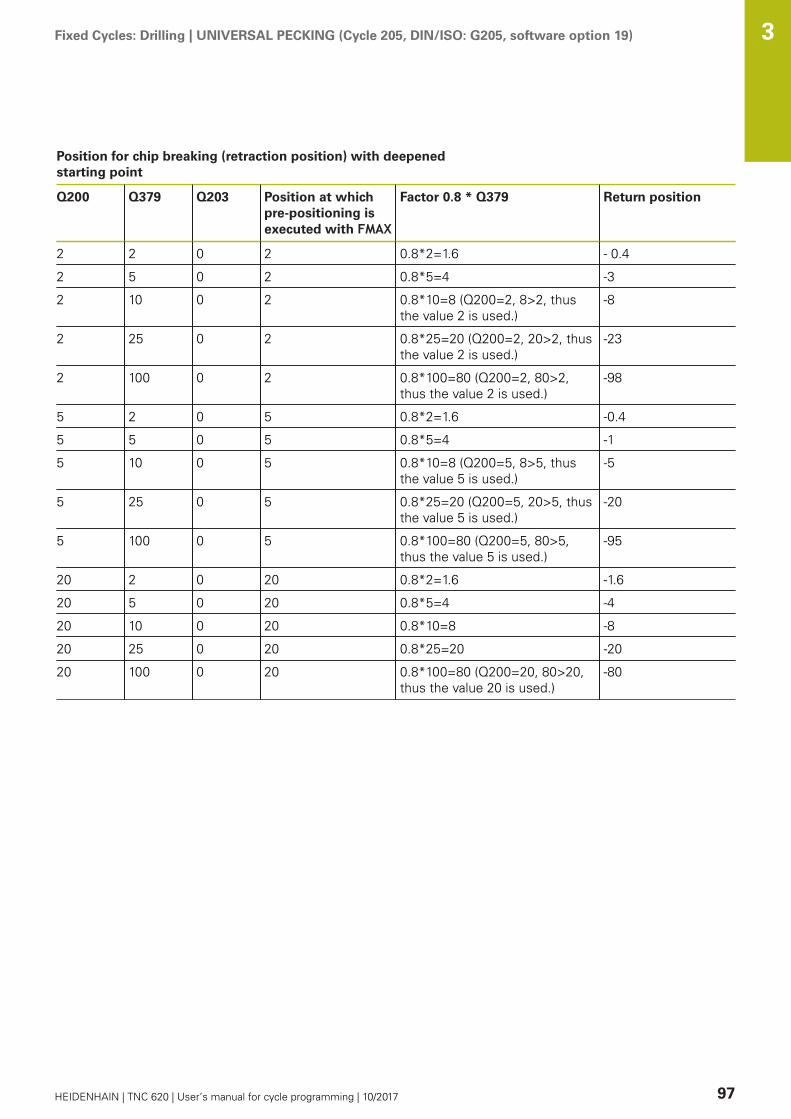
Fixed Cycles: Drilling | UNIVERSAL PECKING (Cycle 205, DIN/ISO: G205, software option 19) 3
HEIDENHAIN | TNC 620 | User’s manual for cycle programming | 10/2017 97
Position for chip breaking (retraction position) with deepenedstarting point
Q200 Q379 Q203 Position at whichpre-positioning isexecuted with FMAX
Factor 0.8 * Q379 Return position
2 2 0 2 0.8*2=1.6 - 0.4
2 5 0 2 0.8*5=4 -3
2 10 0 2 0.8*10=8 (Q200=2, 8>2, thusthe value 2 is used.)
-8
2 25 0 2 0.8*25=20 (Q200=2, 20>2, thusthe value 2 is used.)
-23
2 100 0 2 0.8*100=80 (Q200=2, 80>2,thus the value 2 is used.)
-98
5 2 0 5 0.8*2=1.6 -0.4
5 5 0 5 0.8*5=4 -1
5 10 0 5 0.8*10=8 (Q200=5, 8>5, thusthe value 5 is used.)
-5
5 25 0 5 0.8*25=20 (Q200=5, 20>5, thusthe value 5 is used.)
-20
5 100 0 5 0.8*100=80 (Q200=5, 80>5,thus the value 5 is used.)
-95
20 2 0 20 0.8*2=1.6 -1.6
20 5 0 20 0.8*5=4 -4
20 10 0 20 0.8*10=8 -8
20 25 0 20 0.8*25=20 -20
20 100 0 20 0.8*100=80 (Q200=20, 80>20,thus the value 20 is used.)
-80

Fixed Cycles: Drilling | BORE MILLING (Cycle 208, software option 19) 3
98 HEIDENHAIN | TNC 620 | User’s manual for cycle programming | 10/2017
3.9 BORE MILLING (Cycle 208, softwareoption 19)
Cycle run1 The TNC positions the tool in the tool axis at rapid traverse
FMAX to the programmed set-up clearance above the workpiecesurface and then moves the tool to the bore hole circumferenceon a rounded arc (if enough space is available).
2 The tool mills in a helix from the current position to the firstplunging depth at the programmed feed rate F.
3 When the drilling depth is reached, the TNC once againtraverses a full circle to remove the material remaining after theinitial plunge.
4 The TNC then positions the tool at the center of the hole again.5 Finally the TNC returns to the setup clearance at FMAX. If
programmed, the tool moves to the 2nd set-up clearance atFMAX.

Fixed Cycles: Drilling | BORE MILLING (Cycle 208, software option 19) 3
HEIDENHAIN | TNC 620 | User’s manual for cycle programming | 10/2017 99
Please note while programming:
Program a positioning block for the starting point (holecenter) in the working plane with radius compensationR0.The algebraic sign for the cycle parameter DEPTHdetermines the working direction. If you programDEPTH=0, the cycle will not be executed.If you have entered the bore hole diameter to be thesame as the tool diameter, the TNC will bore directly tothe entered depth without any helical interpolation.An active mirror function does not influence the type ofmilling defined in the cycle.Note that if the infeed distance is too large, the tool orthe workpiece may be damaged.To prevent the infeeds from being too large, enter themaximum plunge angle of the tool in the ANGLE columnof the tool table. The TNC then automatically calculatesthe max. infeed permitted and changes your enteredvalue accordingly.
NOTICEDanger of collision!
If you enter a positive depth with a cycle, the TNC reversescalculation of the pre-positioning. This means that the toolmoves at rapid traverse in the tool axis to set-up clearancebelow the workpiece surface!
Enter depth as negativeEnter in machine parameter displayDepthErr (No. 201003)whether the TNC should output an error message (on) or not(off) if a positive depth is entered
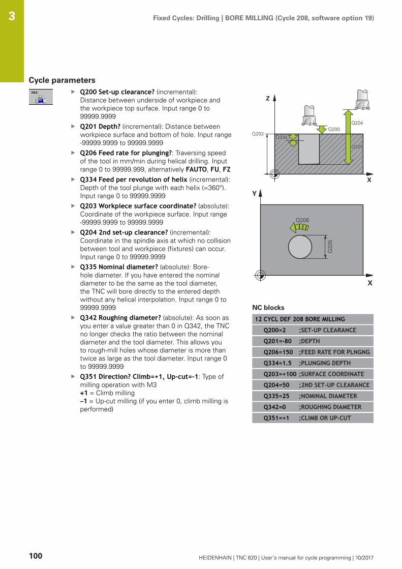
Fixed Cycles: Drilling | BORE MILLING (Cycle 208, software option 19) 3
100 HEIDENHAIN | TNC 620 | User’s manual for cycle programming | 10/2017
Cycle parametersQ200 Set-up clearance? (incremental):Distance between underside of workpiece andthe workpiece top surface. Input range 0 to99999.9999Q201 Depth? (incremental): Distance betweenworkpiece surface and bottom of hole. Input range-99999.9999 to 99999.9999Q206 Feed rate for plunging?: Traversing speedof the tool in mm/min during helical drilling. Inputrange 0 to 99999.999, alternatively FAUTO, FU, FZQ334 Feed per revolution of helix (incremental):Depth of the tool plunge with each helix (=360°).Input range 0 to 99999.9999Q203 Workpiece surface coordinate? (absolute):Coordinate of the workpiece surface. Input range-99999.9999 to 99999.9999Q204 2nd set-up clearance? (incremental):Coordinate in the spindle axis at which no collisionbetween tool and workpiece (fixtures) can occur.Input range 0 to 99999.9999Q335 Nominal diameter? (absolute): Bore-hole diameter. If you have entered the nominaldiameter to be the same as the tool diameter,the TNC will bore directly to the entered depthwithout any helical interpolation. Input range 0 to99999.9999Q342 Roughing diameter? (absolute): As soon asyou enter a value greater than 0 in Q342, the TNCno longer checks the ratio between the nominaldiameter and the tool diameter. This allows youto rough-mill holes whose diameter is more thantwice as large as the tool diameter. Input range 0to 99999.9999Q351 Direction? Climb=+1, Up-cut=-1: Type ofmilling operation with M3+1 = Climb milling–1 = Up-cut milling (if you enter 0, climb milling isperformed)
NC blocks
12 CYCL DEF 208 BORE MILLING
Q200=2 ;SET-UP CLEARANCE
Q201=-80 ;DEPTH
Q206=150 ;FEED RATE FOR PLNGNG
Q334=1.5 ;PLUNGING DEPTH
Q203=+100 ;SURFACE COORDINATE
Q204=50 ;2ND SET-UP CLEARANCE
Q335=25 ;NOMINAL DIAMETER
Q342=0 ;ROUGHING DIAMETER
Q351=+1 ;CLIMB OR UP-CUT

Fixed Cycles: Drilling | SINGLE-LIP DEEP-HOLE DRILLING (Cycle 241, DIN/ISO: G241, software option 19) 3
HEIDENHAIN | TNC 620 | User’s manual for cycle programming | 10/2017 101
3.10 SINGLE-LIP DEEP-HOLE DRILLING (Cycle241, DIN/ISO: G241, software option 19)
Cycle run1 The TNC positions the tool in the spindle axis at rapid traverse
FMAX to the programmed Safety clearance Q200 above theSURFACE COORDINATE Q203
2 Depending on the "Position behavior when working withQ379", Page 94, the TNC switches the spindle speed eitherto the Safety clearance Q200 or to a specific value above thecoordinate surface. see Page 94
3 The TNC executes the approach motion with the direction ofrotation defined in the cycle, with clockwise, counterclockwiseor stationary spindle.
4 The tool drills to the hole depth at the feed rate F, or to theplunging depth if a smaller infeed value has been entered. Theplunging depth is decreased after each infeed by the decrement.If you have entered a dwell depth, the TNC reduces the feedrate by the feed rate factor after the dwell depth has beenreached.
5 If programmed, the tool remains at the hole bottom for chipbreaking.
6 The TNC repeats this process (4 to 5) until the hole depth isreached.
7 After the TNC has reached the hole depth, it switches off thecoolant and resets the drilling speed to the value defined inQ427 ROT.SPEED INFEED/OUT.
8 The TNC positions the tool at the retraction feed rate to theretraction position. Refer to the following document for thevalue of the retraction position in your case: see Page 94
9 If programmed, the tool moves to the 2nd set-up clearance atFMAX

Fixed Cycles: Drilling | SINGLE-LIP DEEP-HOLE DRILLING (Cycle 241, DIN/ISO: G241, software option 19) 3
102 HEIDENHAIN | TNC 620 | User’s manual for cycle programming | 10/2017
Please note while programming:
Program a positioning block for the starting point (holecenter) in the working plane with radius compensationR0.The algebraic sign for the cycle parameter DEPTHdetermines the working direction. If you programDEPTH=0, the cycle will not be executed.
NOTICEDanger of collision!
If you enter a positive depth with a cycle, the TNC reversescalculation of the pre-positioning. This means that the toolmoves at rapid traverse in the tool axis to set-up clearancebelow the workpiece surface!
Enter depth as negativeEnter in machine parameter displayDepthErr (No. 201003)whether the TNC should output an error message (on) or not(off) if a positive depth is entered

Fixed Cycles: Drilling | SINGLE-LIP DEEP-HOLE DRILLING (Cycle 241, DIN/ISO: G241, software option 19) 3
HEIDENHAIN | TNC 620 | User’s manual for cycle programming | 10/2017 103
Cycle parametersQ200 Set-up clearance? (incremental): Distanceof tool tip to Q203 SURFACE COORDINATE. Inputrange 0 to 99999.9999Q201 Depth? (incremental): Distance of Q203SURFACE COORDINATE to bottom of hole. Inputrange -99999.9999 to 99999.9999Q206 Feed rate for plunging?: Traversing speedof the tool in mm/min while drilling. Input range 0to 99999.999, alternatively FAUTO, FUQ211 Dwell time at the depth?: Time in secondsthat the tool remains at the hole bottom. Inputrange 0 to 3600.0000Q203 Workpiece surface coordinate? (absolute):Distance to workpiece datum. Input range-99999.9999 to 99999.9999Q204 2nd set-up clearance? (incremental):Coordinate in the spindle axis at which no collisionbetween tool and workpiece (fixtures) can occur.Input range 0 to 99999.9999Q379 Deepened starting point? (incrementalwith respect to Q203 SURFACE COORDINATE,takes Q200 into account): Starting positionof actual drilling. The TNC moves at Q253 FPRE-POSITIONING to the value Q200 SET-UPCLEARANCE above the deepened starting point.Input range 0 to 99999.9999Q253 Feed rate for pre-positioning?: Definesthe traversing speed of the tool when returning toQ201 DEPTH after Q256 DIST FOR CHIP BRKNG.This feed rate is also in effect when the tool ispositioned to Q379 STARTING POINT (not equal0). Entry in mm/min. Input range 0 to 99999.9999alternatively fmax, FAUTOQ208 Feed rate for retraction?: Traverse speedof tool when moving out of the hole in mm/min.If you enter Q208=0, the TNC retracts the tool atQ206 FEED RATE FOR PLNGNG. Input range 0 to99999.999, alternatively Fmax, FAUTOQ426 Rot. dir. of entry/exit (3/4/5)?: Rotationalspeed at which the tool is to rotate when movinginto and retracting from the hole. Input: 3: Turn the spindle with M34: Turn the spindle with M45: Move with stationary spindle
NC blocks
11 CYCL DEF 241 SINGLE-LIPD.H.DRLNG
Q200=2 ;SET-UP CLEARANCE
Q201=-80 ;DEPTH
Q206=150 ;FEED RATE FOR PLNGNG
Q211=0.25 ;DWELL TIME AT DEPTH
Q203=+100 ;SURFACE COORDINATE
Q204=50 ;2ND SET-UP CLEARANCE
Q379=7.5 ;STARTING POINT
Q253=750 ;F PRE-POSITIONING
Q208=1000 ;RETRACTION FEED RATE
Q426=3 ;DIR. OF SPINDLE ROT.
Q427=25 ;ROT.SPEED INFEED/OUT
Q428=500 ;ROT. SPEED DRILLING
Q429=8 ;COOLANT ON
Q430=9 ;COOLANT OFF
Q435=0 ;DWELL DEPTH
Q401=100 ;FEED RATE FACTOR
Q202=9999 ;MAX. PLUNGING DEPTH
Q212=0 ;DECREMENT
Q205=0 ;MIN. PLUNGING DEPTH
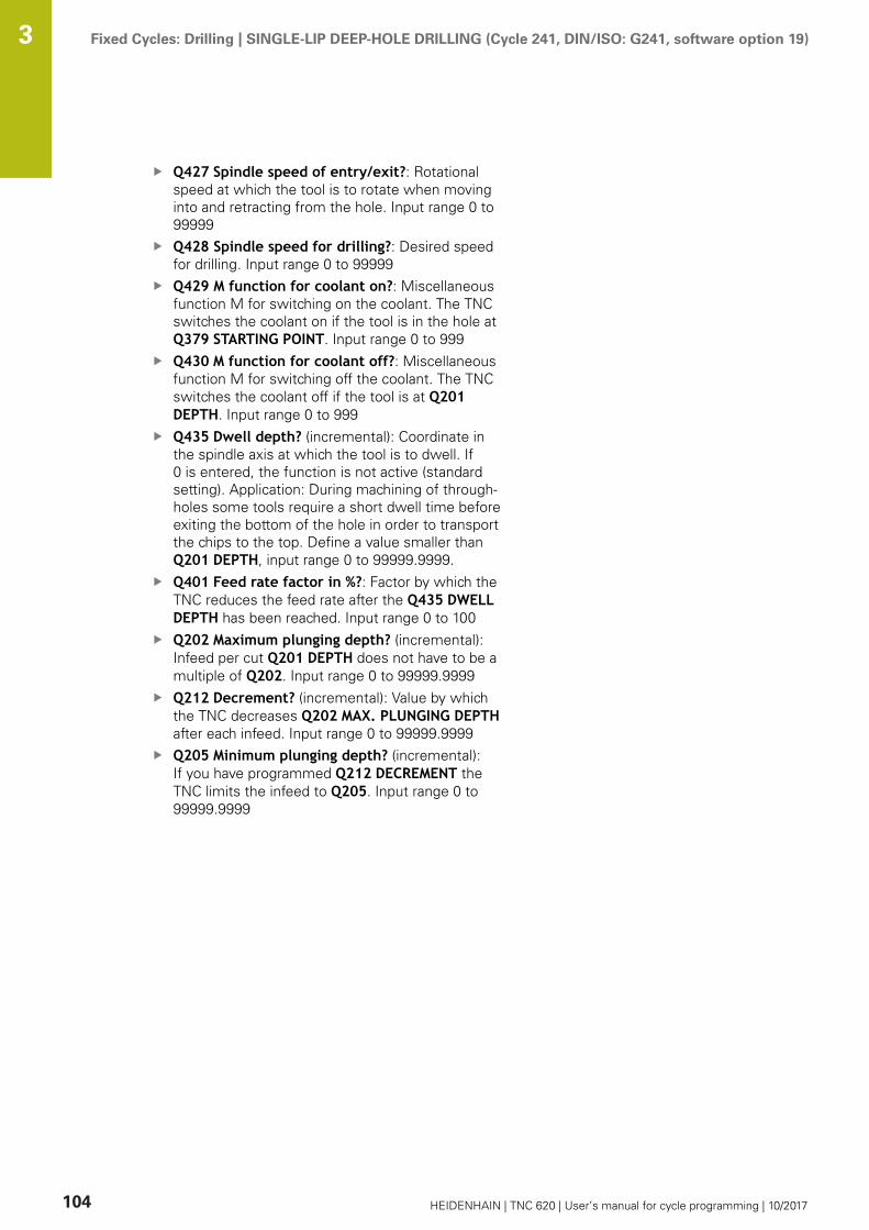
Fixed Cycles: Drilling | SINGLE-LIP DEEP-HOLE DRILLING (Cycle 241, DIN/ISO: G241, software option 19) 3
104 HEIDENHAIN | TNC 620 | User’s manual for cycle programming | 10/2017
Q427 Spindle speed of entry/exit?: Rotationalspeed at which the tool is to rotate when movinginto and retracting from the hole. Input range 0 to99999Q428 Spindle speed for drilling?: Desired speedfor drilling. Input range 0 to 99999Q429 M function for coolant on?: Miscellaneousfunction M for switching on the coolant. The TNCswitches the coolant on if the tool is in the hole atQ379 STARTING POINT. Input range 0 to 999Q430 M function for coolant off?: Miscellaneousfunction M for switching off the coolant. The TNCswitches the coolant off if the tool is at Q201DEPTH. Input range 0 to 999Q435 Dwell depth? (incremental): Coordinate inthe spindle axis at which the tool is to dwell. If0 is entered, the function is not active (standardsetting). Application: During machining of through-holes some tools require a short dwell time beforeexiting the bottom of the hole in order to transportthe chips to the top. Define a value smaller thanQ201 DEPTH, input range 0 to 99999.9999.Q401 Feed rate factor in %?: Factor by which theTNC reduces the feed rate after the Q435 DWELLDEPTH has been reached. Input range 0 to 100Q202 Maximum plunging depth? (incremental):Infeed per cut Q201 DEPTH does not have to be amultiple of Q202. Input range 0 to 99999.9999Q212 Decrement? (incremental): Value by whichthe TNC decreases Q202 MAX. PLUNGING DEPTHafter each infeed. Input range 0 to 99999.9999Q205 Minimum plunging depth? (incremental):If you have programmed Q212 DECREMENT theTNC limits the infeed to Q205. Input range 0 to99999.9999

Fixed Cycles: Drilling | SINGLE-LIP DEEP-HOLE DRILLING (Cycle 241, DIN/ISO: G241, software option 19) 3
HEIDENHAIN | TNC 620 | User’s manual for cycle programming | 10/2017 105
Position behavior when working with Q379Several aspects must be observed when working with very longdrilling tools, e.g. single-lip deep hole drills or extra-long twist drills.The position at which the spindle is switched on is decisive. Withextra-long drills, tool breakage may occur if the tool is not guided.For this reason it is recommended to use the parameter STARTINGPOINT Q379. This parameter enables you to influence the positionat which the TNC activates the spindle.Start of drilling
The parameter STARTING POINT Q379 takes into account SURFACECOORDINATE Q203 and the parameter SET-UP CLEARANCE Q200.The following example demonstrates the relationship between theparameters and how the start position is calculated:STARTING POINT Q379=0
The TNC activates the spindle to SET-UP CLEARANCE Q200 viaSURFACE COORDINATE Q203.
STARTING POINT Q379>0The start of drilling is at a specific value above the deepenedstarting point Q379. This value is calculated as follows:0.2 x Q379 If the result of this calculation is greater than Q200the value is always Q200.Example:SURFACE COORDINATE Q203 =0SET-UP CLEARANCE Q200 =2STARTING POINT Q379 =2The start of drilling is calculated as follows:0.2 x Q379=0.2*2=0.4; start of drilling is 0.4 mm/inch above thedeepened starting point. Thus if the deepened starting point isat -2 the TNC initiates the drilling process at -1.6 mm.The following table shows various examples for calculating thestart of drilling:

Fixed Cycles: Drilling | SINGLE-LIP DEEP-HOLE DRILLING (Cycle 241, DIN/ISO: G241, software option 19) 3
106 HEIDENHAIN | TNC 620 | User’s manual for cycle programming | 10/2017
Start of drilling at deepened starting point
Q200 Q379 Q203 Position at whichpre-positioning isexecuted with FMAX
Factor 0.2 * Q379 Start of drilling
2 2 0 2 0.2*2=0.4 -1.6
2 5 0 2 0.2*5=1 -4
2 10 0 2 0.2*10=2 -8
2 25 0 2 0.2*25=5 (Q200=2, 5>2, thusthe value 2 is used.)
-23
2 100 0 2 0.2*100=20 (Q200=2, 20>2,thus the value 2 is used.)
-98
5 2 0 5 0.2*2=0.4 -1.6
5 5 0 5 0.2*5=1 -4
5 10 0 5 0.2*10=2 -8
5 25 0 5 0.2*25=5 -20
5 100 0 5 0.2*100=20 (Q200=5, 20>5,thus the value 5 is used.)
-95
20 2 0 20 0.2*2=0.4 -1.6
20 5 0 20 0.2*5=1 -4
20 10 0 20 0.2*10=2 -8
20 25 0 20 0.2*25=5 -20
20 100 0 20 0.2*100=20 -80
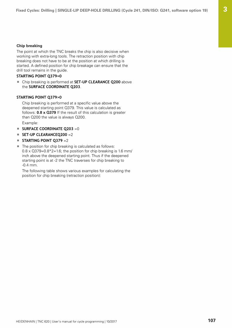
Fixed Cycles: Drilling | SINGLE-LIP DEEP-HOLE DRILLING (Cycle 241, DIN/ISO: G241, software option 19) 3
HEIDENHAIN | TNC 620 | User’s manual for cycle programming | 10/2017 107
Chip breaking
The point at which the TNC breaks the chip is also decisive whenworking with extra-long tools. The retraction position with chipbreaking does not have to be at the position at which drilling isstarted. A defined position for chip breakage can ensure that thedrill tool remains in the guide.STARTING POINT Q379=0
Chip breaking is performed at SET-UP CLEARANCE Q200 abovethe SURFACE COORDINATE Q203.
STARTING POINT Q379>0Chip breaking is performed at a specific value above thedeepened starting point Q379. This value is calculated asfollows: 0.8 x Q379 If the result of this calculation is greaterthan Q200 the value is always Q200.Example:SURFACE COORDINATE Q203 =0SET-UP CLEARANCEQ200 =2STARTING POINT Q379 =2The position for chip breaking is calculated as follows:0.8 x Q379=0.8*2=1.6; the position for chip breaking is 1.6 mm/inch above the deepened starting point. Thus if the deepenedstarting point is at -2 the TNC traverses for chip breaking to-0.4 mm.The following table shows various examples for calculating theposition for chip breaking (retraction position):
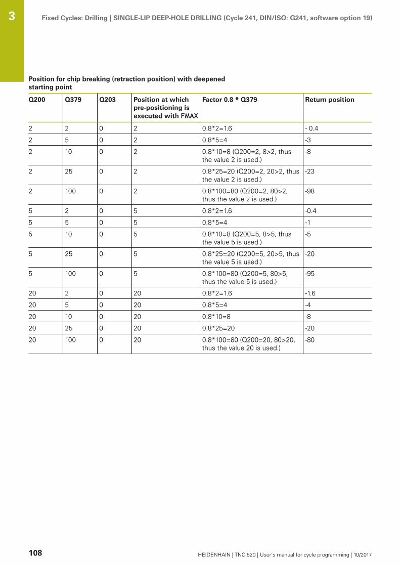
Fixed Cycles: Drilling | SINGLE-LIP DEEP-HOLE DRILLING (Cycle 241, DIN/ISO: G241, software option 19) 3
108 HEIDENHAIN | TNC 620 | User’s manual for cycle programming | 10/2017
Position for chip breaking (retraction position) with deepenedstarting point
Q200 Q379 Q203 Position at whichpre-positioning isexecuted with FMAX
Factor 0.8 * Q379 Return position
2 2 0 2 0.8*2=1.6 - 0.4
2 5 0 2 0.8*5=4 -3
2 10 0 2 0.8*10=8 (Q200=2, 8>2, thusthe value 2 is used.)
-8
2 25 0 2 0.8*25=20 (Q200=2, 20>2, thusthe value 2 is used.)
-23
2 100 0 2 0.8*100=80 (Q200=2, 80>2,thus the value 2 is used.)
-98
5 2 0 5 0.8*2=1.6 -0.4
5 5 0 5 0.8*5=4 -1
5 10 0 5 0.8*10=8 (Q200=5, 8>5, thusthe value 5 is used.)
-5
5 25 0 5 0.8*25=20 (Q200=5, 20>5, thusthe value 5 is used.)
-20
5 100 0 5 0.8*100=80 (Q200=5, 80>5,thus the value 5 is used.)
-95
20 2 0 20 0.8*2=1.6 -1.6
20 5 0 20 0.8*5=4 -4
20 10 0 20 0.8*10=8 -8
20 25 0 20 0.8*25=20 -20
20 100 0 20 0.8*100=80 (Q200=20, 80>20,thus the value 20 is used.)
-80

Fixed Cycles: Drilling | Programming Examples 3
HEIDENHAIN | TNC 620 | User’s manual for cycle programming | 10/2017 109
3.11 Programming Examples
Example: Drilling cycles
0 BEGIN PGM C200 MM
1 BLK FORM 0.1 Z X+0 Y+0 Z-20 Definition of workpiece blank
2 BLK FORM 0.2 X+100 Y+100 Z+0
3 TOOL CALL 1 Z S4500 Tool call (tool radius 3)
4 L Z+250 R0 FMAX Retract the tool
5 CYCL DEF 200 DRILLING Cycle definition
Q200=2 ;SET-UP CLEARANCE
Q201=-15 ;DEPTH
Q206=250 ;FEED RATE FOR PLNGNG
Q202=5 ;PLUNGING DEPTH
Q210=0 ;DWELL TIME AT TOP
Q203=-10 ;SURFACE COORDINATE
Q204=20 ;2ND SET-UP CLEARANCE
Q211=0.2 ;DWELL TIME AT DEPTH
Q395=0 ;DEPTH REFERENCE
6 L X+10 Y+10 R0 FMAX M3 Approach hole 1, spindle ON
7 CYCL CALL Cycle call
8 L Y+90 R0 FMAX M99 Approach hole 2, call cycle
9 L X+90 R0 FMAX M99 Approach hole 3, call cycle
10 L Y+10 R0 FMAX M99 Approach hole 4, call cycle
11 L Z+250 R0 FMAX M2 Retract the tool, end program
12 END PGM C200 MM
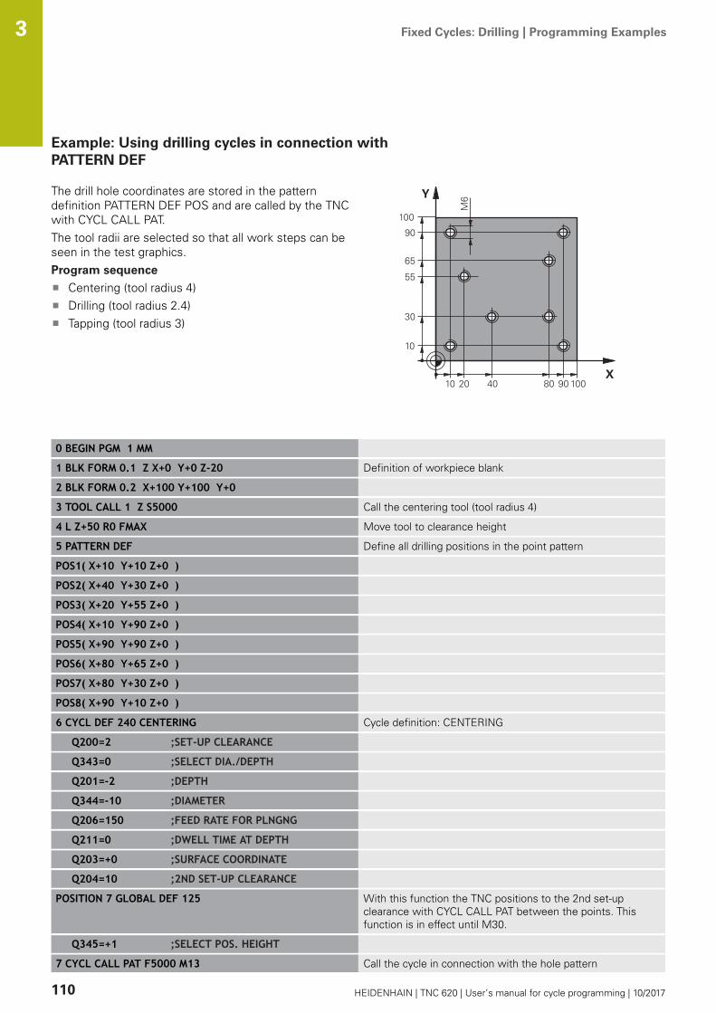
Fixed Cycles: Drilling | Programming Examples 3
110 HEIDENHAIN | TNC 620 | User’s manual for cycle programming | 10/2017
Example: Using drilling cycles in connection withPATTERN DEF
The drill hole coordinates are stored in the patterndefinition PATTERN DEF POS and are called by the TNCwith CYCL CALL PAT.The tool radii are selected so that all work steps can beseen in the test graphics.Program sequence
Centering (tool radius 4)Drilling (tool radius 2.4)Tapping (tool radius 3)
0 BEGIN PGM 1 MM
1 BLK FORM 0.1 Z X+0 Y+0 Z-20 Definition of workpiece blank
2 BLK FORM 0.2 X+100 Y+100 Y+0
3 TOOL CALL 1 Z S5000 Call the centering tool (tool radius 4)
4 L Z+50 R0 FMAX Move tool to clearance height
5 PATTERN DEF Define all drilling positions in the point pattern
POS1( X+10 Y+10 Z+0 )
POS2( X+40 Y+30 Z+0 )
POS3( X+20 Y+55 Z+0 )
POS4( X+10 Y+90 Z+0 )
POS5( X+90 Y+90 Z+0 )
POS6( X+80 Y+65 Z+0 )
POS7( X+80 Y+30 Z+0 )
POS8( X+90 Y+10 Z+0 )
6 CYCL DEF 240 CENTERING Cycle definition: CENTERING
Q200=2 ;SET-UP CLEARANCE
Q343=0 ;SELECT DIA./DEPTH
Q201=-2 ;DEPTH
Q344=-10 ;DIAMETER
Q206=150 ;FEED RATE FOR PLNGNG
Q211=0 ;DWELL TIME AT DEPTH
Q203=+0 ;SURFACE COORDINATE
Q204=10 ;2ND SET-UP CLEARANCE
POSITION 7 GLOBAL DEF 125 With this function the TNC positions to the 2nd set-upclearance with CYCL CALL PAT between the points. Thisfunction is in effect until M30.
Q345=+1 ;SELECT POS. HEIGHT
7 CYCL CALL PAT F5000 M13 Call the cycle in connection with the hole pattern
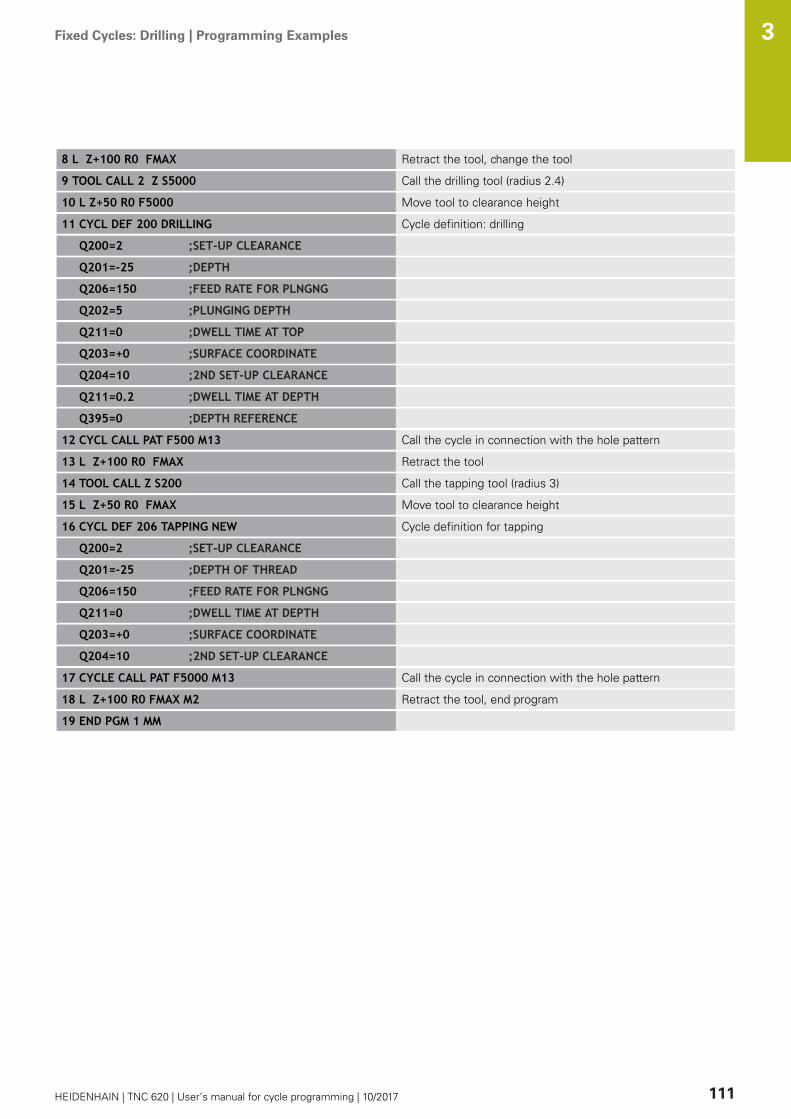
Fixed Cycles: Drilling | Programming Examples 3
HEIDENHAIN | TNC 620 | User’s manual for cycle programming | 10/2017 111
8 L Z+100 R0 FMAX Retract the tool, change the tool
9 TOOL CALL 2 Z S5000 Call the drilling tool (radius 2.4)
10 L Z+50 R0 F5000 Move tool to clearance height
11 CYCL DEF 200 DRILLING Cycle definition: drilling
Q200=2 ;SET-UP CLEARANCE
Q201=-25 ;DEPTH
Q206=150 ;FEED RATE FOR PLNGNG
Q202=5 ;PLUNGING DEPTH
Q211=0 ;DWELL TIME AT TOP
Q203=+0 ;SURFACE COORDINATE
Q204=10 ;2ND SET-UP CLEARANCE
Q211=0.2 ;DWELL TIME AT DEPTH
Q395=0 ;DEPTH REFERENCE
12 CYCL CALL PAT F500 M13 Call the cycle in connection with the hole pattern
13 L Z+100 R0 FMAX Retract the tool
14 TOOL CALL Z S200 Call the tapping tool (radius 3)
15 L Z+50 R0 FMAX Move tool to clearance height
16 CYCL DEF 206 TAPPING NEW Cycle definition for tapping
Q200=2 ;SET-UP CLEARANCE
Q201=-25 ;DEPTH OF THREAD
Q206=150 ;FEED RATE FOR PLNGNG
Q211=0 ;DWELL TIME AT DEPTH
Q203=+0 ;SURFACE COORDINATE
Q204=10 ;2ND SET-UP CLEARANCE
17 CYCLE CALL PAT F5000 M13 Call the cycle in connection with the hole pattern
18 L Z+100 R0 FMAX M2 Retract the tool, end program
19 END PGM 1 MM


4Fixed Cycles:
Tapping / ThreadMilling

Fixed Cycles: Tapping / Thread Milling | Fundamentals 4
114 HEIDENHAIN | TNC 620 | User’s manual for cycle programming | 10/2017
4.1 Fundamentals
OverviewThe TNC offers the following cycles for all types of threadingoperations:
Soft key Cycle Page
206 TAPPING NEWWith a floating tap holder, withautomatic pre-positioning,2nd set-up clearance
115
207 TAPPING NEWWithout a floating tap holder, withautomatic pre-positioning, 2nd set-upclearance
118
209 TAPPING WITH CHIP BREAKINGWithout a floating tap holder, withautomatic pre-positioning, 2nd set-upclearance, chip breaking
122
262 THREAD MILLINGCycle for milling a thread in pre-drilledmaterial
128
263 THREAD MILLING/COUNTERSINKINGCycle for milling a thread in pre-drilledmaterial and machining a countersunkchamfer
131
264 THREAD DRILLING/MILLINGCycle for drilling into solid materialwith subsequent milling of the threadwith a tool
135
265 HELICAL THREAD DRILLING/MILLINGCycle for milling the thread into solidmaterial
139
267 OUTSIDE THREAD MILLINGCycle for milling an external threadand machining a countersunk chamfer
143

Fixed Cycles: Tapping / Thread Milling | TAPPING with a floating tap holder (Cycle 206, DIN/ISO: G206) 4
HEIDENHAIN | TNC 620 | User’s manual for cycle programming | 10/2017 115
4.2 TAPPING with a floating tap holder(Cycle 206, DIN/ISO: G206)
Cycle run1 The TNC positions the tool in the tool axis at rapid traverse
FMAX to the entered set-up clearance above the workpiecesurface.
2 The tool drills to the total hole depth in one movement.3 Once the tool has reached the total hole depth, the direction of
spindle rotation is reversed and the tool is retracted to the set-up clearance at the end of the dwell time. If programmed, thetool moves to the 2nd set-up clearance at FMAX.
4 At the set-up clearance, the direction of spindle rotationreverses once again.

Fixed Cycles: Tapping / Thread Milling | TAPPING with a floating tap holder (Cycle 206, DIN/ISO: G206) 4
116 HEIDENHAIN | TNC 620 | User’s manual for cycle programming | 10/2017
Please note while programming:
Program a positioning block for the starting point (holecenter) in the working plane with radius compensationR0.The algebraic sign for the cycle parameter DEPTHdetermines the working direction. If you programDEPTH=0, the cycle will not be executed.A floating tap holder is required for tapping. It mustcompensate the tolerances between feed rate andspindle speed during the tapping process.For tapping right-hand threads activate the spindle withM3, for left-hand threads use M4.It is possible to use the feed rate potentiometer duringtapping. The machine tool builder sets the configuration(with parameter CfgThreadSpindle>sourceOverride)for this purpose. The TNC then modifies the speedaccordingly.The spindle speed potentiometer is inactive.If you enter the thread pitch of the tap in the Pitchcolumn of the tool table, the TNC compares the threadpitch from the tool table with the thread pitch definedin the cycle. The TNC displays an error message if thevalues do not match. In Cycle 206 the TNC uses theprogrammed rotational speed and the feed rate definedin the cycle to calculate the thread pitch.
NOTICEDanger of collision!
If you enter a positive depth with a cycle, the TNC reversescalculation of the pre-positioning. This means that the toolmoves at rapid traverse in the tool axis to set-up clearancebelow the workpiece surface!
Enter depth as negativeEnter in machine parameter displayDepthErr (No. 201003)whether the TNC should output an error message (on) or not(off) if a positive depth is entered

Fixed Cycles: Tapping / Thread Milling | TAPPING with a floating tap holder (Cycle 206, DIN/ISO: G206) 4
HEIDENHAIN | TNC 620 | User’s manual for cycle programming | 10/2017 117
Cycle parametersQ200 Set-up clearance? (incremental): Distancebetween tool tip and workpiece surface. Inputrange 0 to 99999.9999
Guide value: 4x pitch.Q201 Depth of thread? (incremental): Distancebetween workpiece surface and root of thread.Input range -99999.9999 to 99999.9999Q206 Feed rate for plunging?: Traversing speedof the tool during tapping. Input range 0 to99999.999 alternatively FAUTOQ211 Dwell time at the depth?: Enter a valuebetween 0 and 0.5 seconds to avoid wedgingof the tool during retraction. Input range 0 to3600.0000Q203 Workpiece surface coordinate? (absolute):Coordinate of the workpiece surface. Input range-99999.9999 to 99999.9999Q204 2nd set-up clearance? (incremental):Coordinate in the spindle axis at which no collisionbetween tool and workpiece (fixtures) can occur.Input range 0 to 99999.9999
NC blocks
25 CYCL DEF 206 TAPPING NEW
Q200=2 ;SET-UP CLEARANCE
Q201=-20 ;DEPTH OF THREAD
Q206=150 ;FEED RATE FOR PLNGNG
Q211=0.25 ;DWELL TIME AT DEPTH
Q203=+25 ;SURFACE COORDINATE
Q204=50 ;2ND SET-UP CLEARANCE
The feed rate is calculated as follows: F = S x p
F: Feed rate (mm/min)S: Spindle speed (rpm)p: Thread pitch (mm)
Retracting after a program interruption
If you interrupt program run during tapping with the machine stopbutton, the TNC will display a soft key with which you can retractthe tool.

Fixed Cycles: Tapping / Thread Milling | RIGID TAPPING without a floating tap holder (Cycle 207,DIN/ISO: G207)
4
118 HEIDENHAIN | TNC 620 | User’s manual for cycle programming | 10/2017
4.3 RIGID TAPPING without a floating tapholder (Cycle 207, DIN/ISO: G207)
Cycle runThe TNC cuts the thread without a floating tap holder in one ormore passes.1 The TNC positions the tool in the tool axis at rapid traverse
FMAX to the entered set-up clearance above the workpiecesurface.
2 The tool drills to the total hole depth in one movement.3 It then reverses the direction of spindle rotation again and the
tool is retracted to the setup clearance. If you have entered a2nd set-up clearance the TNC will move the tool with FMAXtowards it.
4 The TNC stops the spindle turning at set-up clearance.

Fixed Cycles: Tapping / Thread Milling | RIGID TAPPING without a floating tap holder (Cycle 207,DIN/ISO: G207)
4
HEIDENHAIN | TNC 620 | User’s manual for cycle programming | 10/2017 119
Please note while programming:
Machine and TNC must be specially prepared by themachine tool builder for use of this cycle.This cycle is effective only for machines with servo-controlled spindle.
Program a positioning block for the starting point (holecenter) in the working plane with radius compensationR0.The algebraic sign for the cycle parameter DEPTHdetermines the working direction. If you programDEPTH=0, the cycle will not be executed.It is possible to use the feed rate potentiometer duringtapping. The machine tool builder sets the configuration(with parameter CfgThreadSpindle>sourceOverride)for this purpose. The TNC then modifies the speedaccordingly.The spindle speed potentiometer is inactive.If you program M3 (or M4) before this cycle, thespindle rotates after the end of the cycle (at the speedprogrammed in the TOOL CALL block).If you do not program M3 (or M4) before this cycle, thespindle stands still after the end of the cycle. Then youmust restart the spindle with M3 (or M4) before thenext operation.If you enter the thread pitch of the tap in the Pitchcolumn of the tool table, the TNC compares the threadpitch from the tool table with the thread pitch definedin the cycle. The TNC displays an error message if thevalues do not match.
NOTICEDanger of collision!
If you enter a positive depth with a cycle, the TNC reversescalculation of the pre-positioning. This means that the toolmoves at rapid traverse in the tool axis to set-up clearancebelow the workpiece surface!
Enter depth as negativeEnter in machine parameter displayDepthErr (No. 201003)whether the TNC should output an error message (on) or not(off) if a positive depth is entered

Fixed Cycles: Tapping / Thread Milling | RIGID TAPPING without a floating tap holder (Cycle 207,DIN/ISO: G207)
4
120 HEIDENHAIN | TNC 620 | User’s manual for cycle programming | 10/2017
Cycle parametersQ200 Set-up clearance? (incremental): Distancebetween tool tip and workpiece surface. Inputrange 0 to 99999.9999Q201 Depth of thread? (incremental): Distancebetween workpiece surface and root of thread.Input range -99999.9999 to 99999.9999Q239 Pitch?: Pitch of the thread. The algebraicsign differentiates between right-hand and left-hand threads:+ = right-hand thread–= left-hand threadInput range -99.9999 to 99.9999Q203 Workpiece surface coordinate? (absolute):Coordinate of the workpiece surface. Input range-99999.9999 to 99999.9999Q204 2nd set-up clearance? (incremental):Coordinate in the spindle axis at which no collisionbetween tool and workpiece (fixtures) can occur.Input range 0 to 99999.9999
NC blocks
26 CYCL DEF 207 RIGID TAPPING NEW
Q200=2 ;SET-UP CLEARANCE
Q201=-20 ;DEPTH OF THREAD
Q239=+1 ;THREAD PITCH
Q203=+25 ;SURFACE COORDINATE
Q204=50 ;2ND SET-UP CLEARANCE

Fixed Cycles: Tapping / Thread Milling | RIGID TAPPING without a floating tap holder (Cycle 207,DIN/ISO: G207)
4
HEIDENHAIN | TNC 620 | User’s manual for cycle programming | 10/2017 121
Retracting after a program interruptionRetracting in the Manual Operation mode
You can interrupt the thread cutting process by pressing the NCStop key. A soft key for retracting the tool from the thread isdisplayed in the soft-key row below the screen. When you pressthis soft key and the NC Start key, the tool retracts from thehole and returns to the starting point of machining. The spindleis stopped automatically and the TNC displays a message.
Retracting in the Program Run, Single Block or Full Sequencemode
You can interrupt the thread cutting process by pressing theNC Stop key. The TNC shows the soft key MANUAL TRAVERSE.After pressing MANUAL TRAVERSE you can retract the toolin the active spindle axis. To resume machining after theinterruption, press the RESTORE POSITION soft key and NCStart. The TNC moves the tool back to the position it hadassumed before the NC Stop key was pressed.
NOTICEDanger of collision!
A danger of collision exists if you move the tool during retractionin a negative direction instead of e.g. in a positive direction.
When retracting the tool you can move it in the positive andnegative tool axis directionsBe aware of the direction in which you retract the tool fromthe hole before retracting
Fixed Cycles: Tapping / Thread Milling | TAPPING WITH CHIP BREAKING (Cycle 209, DIN/ISO: G209, softwareoption 19)
4
122 HEIDENHAIN | TNC 620 | User’s manual for cycle programming | 10/2017
4.4 TAPPING WITH CHIP BREAKING (Cycle209, DIN/ISO: G209, software option 19)
Cycle runThe TNC machines the thread in several passes until it reaches theprogrammed depth. You can define in a parameter whether the toolis to be retracted completely from the hole for chip breaking.1 The TNC positions the tool in the tool axis at rapid traverse
FMAX to the programmed set-up clearance above the workpiecesurface. There it carries out an oriented spindle stop.
2 The tool moves to the programmed infeed depth, reverses thedirection of spindle rotation and retracts by a specific distanceor completely for chip release, depending on the definition. Ifyou have defined a factor for increasing the spindle speed, theTNC retracts from the hole at the corresponding speed.
3 It then reverses the direction of spindle rotation again andadvances to the next infeed depth.
4 The TNC repeats this process (2 to 3) until the programmedthread depth is reached.
5 The tool is then retracted to set-up clearance. If programmed,the tool moves to the 2nd set-up clearance at FMAX.
6 The TNC stops the spindle turning at set-up clearance.

Fixed Cycles: Tapping / Thread Milling | TAPPING WITH CHIP BREAKING (Cycle 209, DIN/ISO: G209, softwareoption 19)
4
HEIDENHAIN | TNC 620 | User’s manual for cycle programming | 10/2017 123
Please note while programming:
Machine and TNC must be specially prepared by themachine tool builder for use of this cycle.This cycle is effective only for machines with servo-controlled spindle.
Program a positioning block for the starting point (holecenter) in the working plane with radius compensationR0.The algebraic sign for the cycle parameter "thread depth"determines the working direction.It is possible to use the feed rate potentiometer duringtapping. The machine tool builder sets the configuration(with parameter CfgThreadSpindle>sourceOverride)for this purpose. The TNC then modifies the speedaccordingly.The spindle speed potentiometer is inactive.If you defined an rpm factor for fast retraction in cycleparameter Q403, the TNC limits the speed to themaximum speed of the active gear range.If you program M3 (or M4) before this cycle, thespindle rotates after the end of the cycle (at the speedprogrammed in the TOOL CALL block).If you do not program M3 (or M4) before this cycle, thespindle stands still after the end of the cycle. Then youmust restart the spindle with M3 (or M4) before thenext operation.If you enter the thread pitch of the tap in the Pitchcolumn of the tool table, the TNC compares the threadpitch from the tool table with the thread pitch definedin the cycle. The TNC displays an error message if thevalues do not match.
NOTICEDanger of collision!
If you enter a positive depth with a cycle, the TNC reversescalculation of the pre-positioning. This means that the toolmoves at rapid traverse in the tool axis to set-up clearancebelow the workpiece surface!
Enter depth as negativeEnter in machine parameter displayDepthErr (No. 201003)whether the TNC should output an error message (on) or not(off) if a positive depth is entered
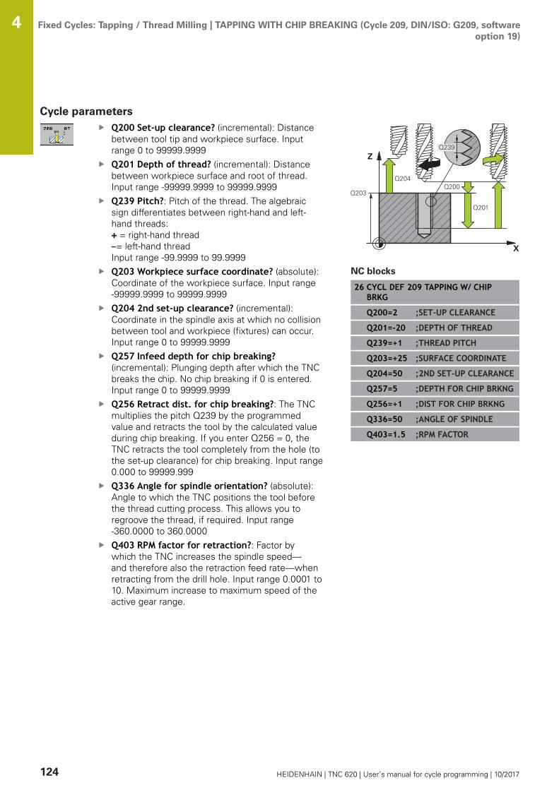
Fixed Cycles: Tapping / Thread Milling | TAPPING WITH CHIP BREAKING (Cycle 209, DIN/ISO: G209, softwareoption 19)
4
124 HEIDENHAIN | TNC 620 | User’s manual for cycle programming | 10/2017
Cycle parametersQ200 Set-up clearance? (incremental): Distancebetween tool tip and workpiece surface. Inputrange 0 to 99999.9999Q201 Depth of thread? (incremental): Distancebetween workpiece surface and root of thread.Input range -99999.9999 to 99999.9999Q239 Pitch?: Pitch of the thread. The algebraicsign differentiates between right-hand and left-hand threads:+ = right-hand thread–= left-hand threadInput range -99.9999 to 99.9999Q203 Workpiece surface coordinate? (absolute):Coordinate of the workpiece surface. Input range-99999.9999 to 99999.9999Q204 2nd set-up clearance? (incremental):Coordinate in the spindle axis at which no collisionbetween tool and workpiece (fixtures) can occur.Input range 0 to 99999.9999Q257 Infeed depth for chip breaking?(incremental): Plunging depth after which the TNCbreaks the chip. No chip breaking if 0 is entered.Input range 0 to 99999.9999Q256 Retract dist. for chip breaking?: The TNCmultiplies the pitch Q239 by the programmedvalue and retracts the tool by the calculated valueduring chip breaking. If you enter Q256 = 0, theTNC retracts the tool completely from the hole (tothe set-up clearance) for chip breaking. Input range0.000 to 99999.999Q336 Angle for spindle orientation? (absolute):Angle to which the TNC positions the tool beforethe thread cutting process. This allows you toregroove the thread, if required. Input range-360.0000 to 360.0000Q403 RPM factor for retraction?: Factor bywhich the TNC increases the spindle speed—and therefore also the retraction feed rate—whenretracting from the drill hole. Input range 0.0001 to10. Maximum increase to maximum speed of theactive gear range.
NC blocks
26 CYCL DEF 209 TAPPING W/ CHIPBRKG
Q200=2 ;SET-UP CLEARANCE
Q201=-20 ;DEPTH OF THREAD
Q239=+1 ;THREAD PITCH
Q203=+25 ;SURFACE COORDINATE
Q204=50 ;2ND SET-UP CLEARANCE
Q257=5 ;DEPTH FOR CHIP BRKNG
Q256=+1 ;DIST FOR CHIP BRKNG
Q336=50 ;ANGLE OF SPINDLE
Q403=1.5 ;RPM FACTOR
Fixed Cycles: Tapping / Thread Milling | TAPPING WITH CHIP BREAKING (Cycle 209, DIN/ISO: G209, softwareoption 19)
4
HEIDENHAIN | TNC 620 | User’s manual for cycle programming | 10/2017 125
Retracting after a program interruption
Retracting in the Manual Operation mode
You can interrupt the thread cutting process by pressing the NCStop key. A soft key for retracting the tool from the thread isdisplayed in the soft-key row below the screen. When you pressthis soft key and the NC Start key, the tool retracts from thehole and returns to the starting point of machining. The spindleis stopped automatically and the TNC displays a message.
Retracting in the Program Run, Single Block or Full Sequencemode
You can interrupt the thread cutting process by pressing theNC Stop key. The TNC shows the soft key MANUAL TRAVERSE.After pressing MANUAL TRAVERSE you can retract the toolin the active spindle axis. To resume machining after theinterruption, press the RESTORE POSITION soft key and NCStart. The TNC moves the tool back to the position it hadassumed before the NC Stop key was pressed.
NOTICEDanger of collision!
A danger of collision exists if you move the tool during retractionin a negative direction instead of e.g. in a positive direction.
When retracting the tool you can move it in the positive andnegative tool axis directionsBe aware of the direction in which you retract the tool fromthe hole before retracting
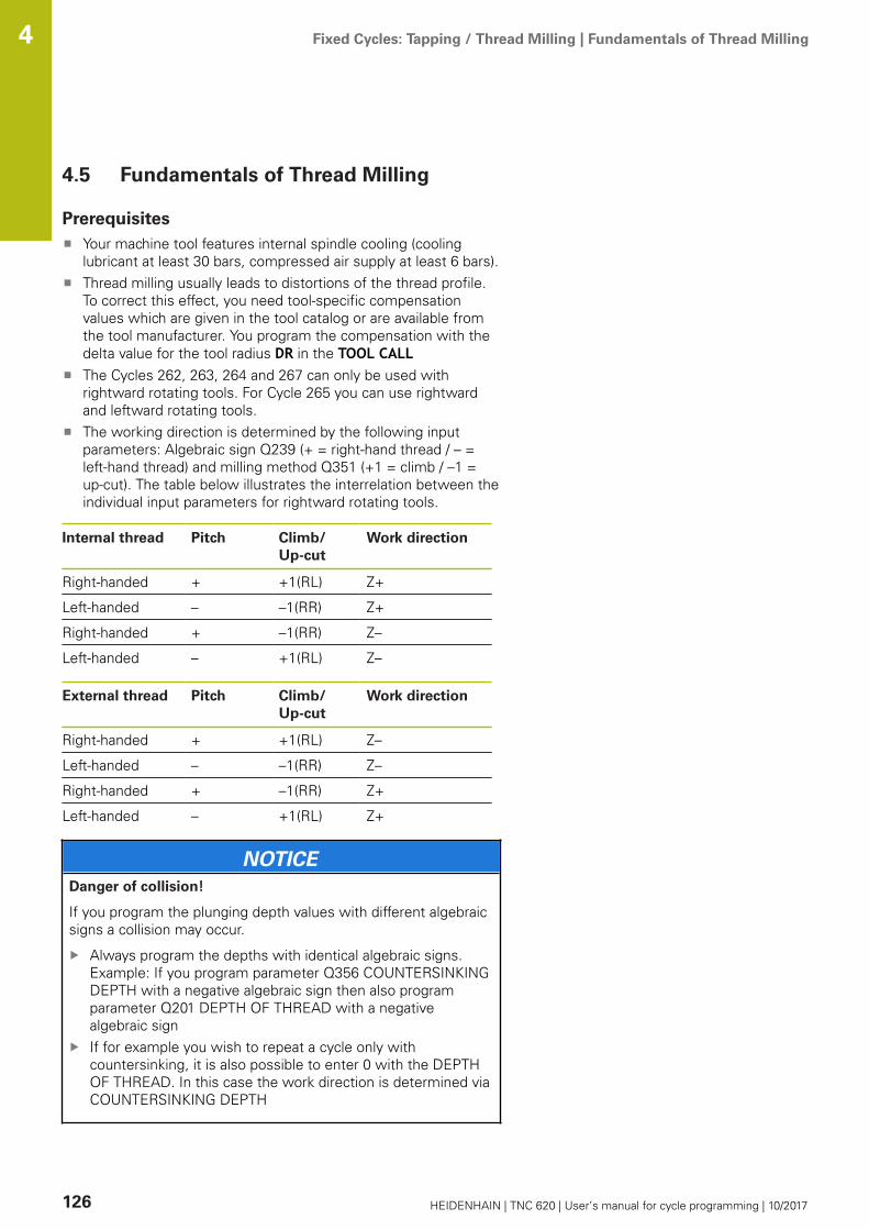
Fixed Cycles: Tapping / Thread Milling | Fundamentals of Thread Milling 4
126 HEIDENHAIN | TNC 620 | User’s manual for cycle programming | 10/2017
4.5 Fundamentals of Thread Milling
PrerequisitesYour machine tool features internal spindle cooling (coolinglubricant at least 30 bars, compressed air supply at least 6 bars).Thread milling usually leads to distortions of the thread profile.To correct this effect, you need tool-specific compensationvalues which are given in the tool catalog or are available fromthe tool manufacturer. You program the compensation with thedelta value for the tool radius DR in the TOOL CALLThe Cycles 262, 263, 264 and 267 can only be used withrightward rotating tools. For Cycle 265 you can use rightwardand leftward rotating tools.The working direction is determined by the following inputparameters: Algebraic sign Q239 (+ = right-hand thread / – =left-hand thread) and milling method Q351 (+1 = climb / –1 =up-cut). The table below illustrates the interrelation between theindividual input parameters for rightward rotating tools.
Internal thread Pitch Climb/Up-cut
Work direction
Right-handed + +1(RL) Z+
Left-handed – –1(RR) Z+
Right-handed + –1(RR) Z–
Left-handed – +1(RL) Z–
External thread Pitch Climb/Up-cut
Work direction
Right-handed + +1(RL) Z–
Left-handed – –1(RR) Z–
Right-handed + –1(RR) Z+
Left-handed – +1(RL) Z+
NOTICEDanger of collision!
If you program the plunging depth values with different algebraicsigns a collision may occur.
Always program the depths with identical algebraic signs.Example: If you program parameter Q356 COUNTERSINKINGDEPTH with a negative algebraic sign then also programparameter Q201 DEPTH OF THREAD with a negativealgebraic signIf for example you wish to repeat a cycle only withcountersinking, it is also possible to enter 0 with the DEPTHOF THREAD. In this case the work direction is determined viaCOUNTERSINKING DEPTH

Fixed Cycles: Tapping / Thread Milling | Fundamentals of Thread Milling 4
HEIDENHAIN | TNC 620 | User’s manual for cycle programming | 10/2017 127
NOTICEDanger of collision!
A collision may occur if, upon tool breakage, you retract the toolfrom the hole in the direction of the tool axis only.
Stop the program run if the tool breaksChange to Positioning with Manual Data Input mode ofoperationFirst move the tool in a linear movement towards the holecenterRetract the tool in the tool axis direction
The TNC references the programmed feed rate duringthread milling to the tool cutting edge. Since the TNC,however, always displays the feed rate relative to thepath of the tool tip, the displayed value does not matchthe programmed value.The machining direction of the thread changes if youexecute a thread milling cycle in connection with Cycle 8MIRROR IMAGE in only one axis.

Fixed Cycles: Tapping / Thread Milling | THREAD MILLING (Cycle 262, DIN/ISO: G262, software option 19) 4
128 HEIDENHAIN | TNC 620 | User’s manual for cycle programming | 10/2017
4.6 THREAD MILLING (Cycle 262, DIN/ISO:G262, software option 19)
Cycle run1 The TNC positions the tool in the tool axis at rapid traverse
FMAX to the entered set-up clearance above the workpiecesurface.
2 The tool moves at the programmed feed rate for pre-positioningto the starting plane. The starting plane is derived from thealgebraic sign of the thread pitch, the milling method (climb orup-cut milling) and the number of threads per step.
3 The tool then moves tangentially on a helical path to the threadmajor diameter. Before the helical approach, a compensatingmotion of the tool axis is carried out in order to begin at theprogrammed starting plane for the thread path.
4 Depending on the setting of the parameter for the number ofthreads, the tool mills the thread in one helical movement, inseveral offset helical movements or in one continuous helicalmovement.
5 After that the tool departs the contour tangentially and returnsto the starting point in the working plane.
6 At the end of the cycle, the TNC retracts the tool in rapidtraverse to setup clearance or, if programmed, to the 2nd setupclearance.
Fixed Cycles: Tapping / Thread Milling | THREAD MILLING (Cycle 262, DIN/ISO: G262, software option 19) 4
HEIDENHAIN | TNC 620 | User’s manual for cycle programming | 10/2017 129
Please note while programming:
Program a positioning block for the starting point (holecenter) in the working plane with radius compensationR0.The algebraic sign for the cycle parameter "thread depth"determines the working direction.If you program the thread DEPTH = 0, the cycle will notbe executed.The nominal thread diameter is approached in a semi-circle from the center. A pre-positioning movement tothe side is carried out if the pitch of the tool diameter isfour times smaller than the nominal thread diameter.Note that the TNC makes a compensation movement inthe tool axis before the approach movement. The lengthof the compensation movement is at most half of thethread pitch. Ensure sufficient space in the hole!If you change the thread depth, the TNC automaticallychanges the starting point for the helical movement.
NOTICEDanger of collision!
If you enter a positive depth with a cycle, the TNC reversescalculation of the pre-positioning. This means that the toolmoves at rapid traverse in the tool axis to set-up clearancebelow the workpiece surface!
Enter depth as negativeEnter in machine parameter displayDepthErr (No. 201003)whether the TNC should output an error message (on) or not(off) if a positive depth is entered
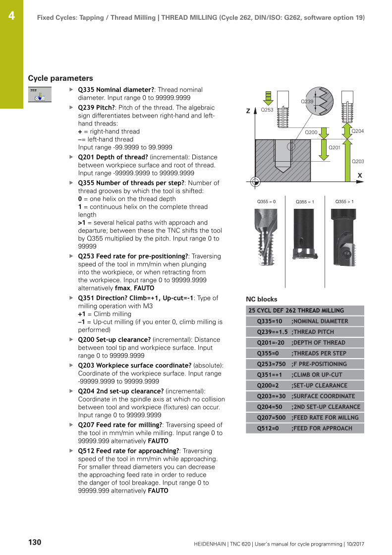
Fixed Cycles: Tapping / Thread Milling | THREAD MILLING (Cycle 262, DIN/ISO: G262, software option 19) 4
130 HEIDENHAIN | TNC 620 | User’s manual for cycle programming | 10/2017
Cycle parametersQ335 Nominal diameter?: Thread nominaldiameter. Input range 0 to 99999.9999Q239 Pitch?: Pitch of the thread. The algebraicsign differentiates between right-hand and left-hand threads:+ = right-hand thread–= left-hand threadInput range -99.9999 to 99.9999Q201 Depth of thread? (incremental): Distancebetween workpiece surface and root of thread.Input range -99999.9999 to 99999.9999Q355 Number of threads per step?: Number ofthread grooves by which the tool is shifted:0 = one helix on the thread depth 1 = continuous helix on the complete threadlength >1 = several helical paths with approach anddeparture; between these the TNC shifts the toolby Q355 multiplied by the pitch. Input range 0 to99999Q253 Feed rate for pre-positioning?: Traversingspeed of the tool in mm/min when plunginginto the workpiece, or when retracting fromthe workpiece. Input range 0 to 99999.9999alternatively fmax, FAUTOQ351 Direction? Climb=+1, Up-cut=-1: Type ofmilling operation with M3+1 = Climb milling–1 = Up-cut milling (if you enter 0, climb milling isperformed)Q200 Set-up clearance? (incremental): Distancebetween tool tip and workpiece surface. Inputrange 0 to 99999.9999Q203 Workpiece surface coordinate? (absolute):Coordinate of the workpiece surface. Input range-99999.9999 to 99999.9999Q204 2nd set-up clearance? (incremental):Coordinate in the spindle axis at which no collisionbetween tool and workpiece (fixtures) can occur.Input range 0 to 99999.9999Q207 Feed rate for milling?: Traversing speed ofthe tool in mm/min while milling. Input range 0 to99999.999 alternatively FAUTOQ512 Feed rate for approaching?: Traversingspeed of the tool in mm/min while approaching.For smaller thread diameters you can decreasethe approaching feed rate in order to reducethe danger of tool breakage. Input range 0 to99999.999 alternatively FAUTO
NC blocks
25 CYCL DEF 262 THREAD MILLING
Q335=10 ;NOMINAL DIAMETER
Q239=+1.5 ;THREAD PITCH
Q201=-20 ;DEPTH OF THREAD
Q355=0 ;THREADS PER STEP
Q253=750 ;F PRE-POSITIONING
Q351=+1 ;CLIMB OR UP-CUT
Q200=2 ;SET-UP CLEARANCE
Q203=+30 ;SURFACE COORDINATE
Q204=50 ;2ND SET-UP CLEARANCE
Q207=500 ;FEED RATE FOR MILLNG
Q512=0 ;FEED FOR APPROACH

Fixed Cycles: Tapping / Thread Milling | THREAD MILLING/COUNTERSINKING (Cycle 263, DIN/ISO: G263,software option 19)
4
HEIDENHAIN | TNC 620 | User’s manual for cycle programming | 10/2017 131
4.7 THREAD MILLING/COUNTERSINKING(Cycle 263, DIN/ISO: G263, softwareoption 19)
Cycle run1 The TNC positions the tool in the tool axis at rapid traverse
FMAX to the entered set-up clearance above the workpiecesurface.
Countersinking
2 The tool moves at the feed rate for pre-positioning to thecountersinking depth minus the set-up clearance, and then atthe feed rate for countersinking to the countersinking depth.
3 If a safety clearance to the side has been entered, the TNCimmediately positions the tool at the feed rate for pre-positioning to the countersinking depth.
4 Then, depending on the available space, the TNC makes atangential approach to the core diameter, either tangentiallyfrom the center or with a pre-positioning move to the side, andfollows a circular path.
Countersinking at front
5 The tool moves at the feed rate for pre-positioning to the sinkingdepth at front.
6 The TNC positions the tool without compensation from thecenter on a semicircle to the offset at front, and then follows acircular path at the feed rate for countersinking.
7 The tool then moves in a semicircle to the hole center.Thread milling
8 The TNC moves the tool at the programmed feed rate for pre-positioning to the starting plane for the thread. The startingplane is determined from the thread pitch and the type ofmilling (climb or up-cut).
9 Then the tool moves tangentially on a helical path to the threaddiameter and mills the thread with a 360° helical motion.
10 After that the tool departs the contour tangentially and returnsto the starting point in the working plane.
11 At the end of the cycle, the TNC retracts the tool in rapidtraverse to setup clearance or, if programmed, to the 2nd setupclearance.

Fixed Cycles: Tapping / Thread Milling | THREAD MILLING/COUNTERSINKING (Cycle 263, DIN/ISO: G263,software option 19)
4
132 HEIDENHAIN | TNC 620 | User’s manual for cycle programming | 10/2017
Please note while programming:
Program a positioning block for the starting point (holecenter) in the working plane with radius compensationR0.The algebraic sign of the cycle parameters depth ofthread, countersinking depth or sinking depth at frontdetermines the working direction. The working directionis defined in the following sequence:1. Thread depth 2. Countersinking depth3. Depth at frontIf you program a depth parameter to be 0, the TNC doesnot execute that step.If you want to countersink at front, define thecountersinking depth as 0.Program the thread depth as a value smaller than thecountersinking depth by at least one-third the threadpitch.
NOTICEDanger of collision!
If you enter a positive depth with a cycle, the TNC reversescalculation of the pre-positioning. This means that the toolmoves at rapid traverse in the tool axis to set-up clearancebelow the workpiece surface!
Enter depth as negativeEnter in machine parameter displayDepthErr (No. 201003)whether the TNC should output an error message (on) or not(off) if a positive depth is entered
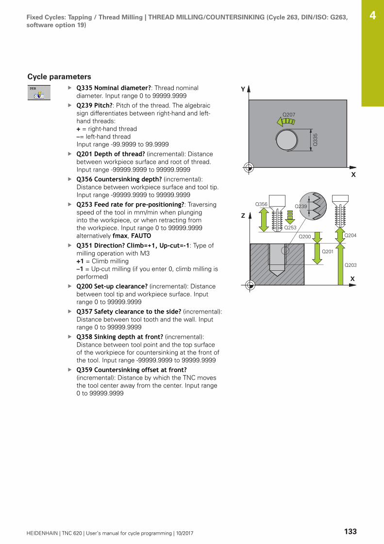
Fixed Cycles: Tapping / Thread Milling | THREAD MILLING/COUNTERSINKING (Cycle 263, DIN/ISO: G263,software option 19)
4
HEIDENHAIN | TNC 620 | User’s manual for cycle programming | 10/2017 133
Cycle parametersQ335 Nominal diameter?: Thread nominaldiameter. Input range 0 to 99999.9999Q239 Pitch?: Pitch of the thread. The algebraicsign differentiates between right-hand and left-hand threads:+ = right-hand thread–= left-hand threadInput range -99.9999 to 99.9999Q201 Depth of thread? (incremental): Distancebetween workpiece surface and root of thread.Input range -99999.9999 to 99999.9999Q356 Countersinking depth? (incremental):Distance between workpiece surface and tool tip.Input range -99999.9999 to 99999.9999Q253 Feed rate for pre-positioning?: Traversingspeed of the tool in mm/min when plunginginto the workpiece, or when retracting fromthe workpiece. Input range 0 to 99999.9999alternatively fmax, FAUTOQ351 Direction? Climb=+1, Up-cut=-1: Type ofmilling operation with M3+1 = Climb milling–1 = Up-cut milling (if you enter 0, climb milling isperformed)Q200 Set-up clearance? (incremental): Distancebetween tool tip and workpiece surface. Inputrange 0 to 99999.9999Q357 Safety clearance to the side? (incremental):Distance between tool tooth and the wall. Inputrange 0 to 99999.9999Q358 Sinking depth at front? (incremental):Distance between tool point and the top surfaceof the workpiece for countersinking at the front ofthe tool. Input range -99999.9999 to 99999.9999Q359 Countersinking offset at front?(incremental): Distance by which the TNC movesthe tool center away from the center. Input range0 to 99999.9999

Fixed Cycles: Tapping / Thread Milling | THREAD MILLING/COUNTERSINKING (Cycle 263, DIN/ISO: G263,software option 19)
4
134 HEIDENHAIN | TNC 620 | User’s manual for cycle programming | 10/2017
Q203 Workpiece surface coordinate? (absolute):Coordinate of the workpiece surface. Input range-99999.9999 to 99999.9999Q204 2nd set-up clearance? (incremental):Coordinate in the spindle axis at which no collisionbetween tool and workpiece (fixtures) can occur.Input range 0 to 99999.9999Q254 Feed rate for counterboring?: Traversingspeed of the tool in mm/min during counterboring.Input range 0 to 99999.9999 alternatively FAUTO,fuQ207 Feed rate for milling?: Traversing speed ofthe tool in mm/min while milling. Input range 0 to99999.999 alternatively FAUTOQ512 Feed rate for approaching?: Traversingspeed of the tool in mm/min while approaching.For smaller thread diameters you can decreasethe approaching feed rate in order to reducethe danger of tool breakage. Input range 0 to99999.999 alternatively FAUTO
NC blocks
25 CYCL DEF 263 THREAD MLLNG/CNTSNKG
Q335=10 ;NOMINAL DIAMETER
Q239=+1.5 ;THREAD PITCH
Q201=-16 ;DEPTH OF THREAD
Q356=-20 ;COUNTERSINKING DEPTH
Q253=750 ;F PRE-POSITIONING
Q351=+1 ;CLIMB OR UP-CUT
Q200=2 ;SET-UP CLEARANCE
Q357=0.2 ;CLEARANCE TO SIDE
Q358=+0 ;DEPTH AT FRONT
Q359=+0 ;OFFSET AT FRONT
Q203=+30 ;SURFACE COORDINATE
Q204=50 ;2ND SET-UP CLEARANCE
Q254=150 ;F COUNTERBORING
Q207=500 ;FEED RATE FOR MILLNG
Q512=0 ;FEED FOR APPROACH

Fixed Cycles: Tapping / Thread Milling | THREAD DRILLING/MILLING (Cycle 264, DIN/ISO: G264, softwareoption 19)
4
HEIDENHAIN | TNC 620 | User’s manual for cycle programming | 10/2017 135
4.8 THREAD DRILLING/MILLING (Cycle 264,DIN/ISO: G264, software option 19)
Cycle run1 The TNC positions the tool in the tool axis at rapid traverse
FMAX to the entered set-up clearance above the workpiecesurface.
Drilling
2 The tool drills to the first plunging depth at the programmedfeed rate for plunging.
3 If you have programmed chip breaking, the tool then retractsby the entered retraction value. If you are working withoutchip breaking, the tool is moved at rapid traverse to the set-upclearance, and then at FMAX to the entered starting positionabove the first plunging depth.
4 The tool then advances with another infeed at the programmedfeed rate.
5 The TNC repeats this process (2 to 4) until the programmedtotal hole depth is reached.
Countersinking at front
6 The tool moves at the feed rate for pre-positioning to the sinkingdepth at front.
7 The TNC positions the tool without compensation from thecenter on a semicircle to the offset at front, and then follows acircular path at the feed rate for countersinking.
8 The tool then moves in a semicircle to the hole center.Thread milling
9 The TNC moves the tool at the programmed feed rate for pre-positioning to the starting plane for the thread. The startingplane is determined from the thread pitch and the type ofmilling (climb or up-cut).
10 Then the tool moves tangentially on a helical path to the threaddiameter and mills the thread with a 360° helical motion.
11 After that the tool departs the contour tangentially and returnsto the starting point in the working plane.
12 At the end of the cycle, the TNC retracts the tool in rapidtraverse to setup clearance or, if programmed, to the 2nd setupclearance.
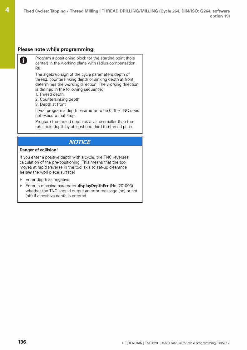
Fixed Cycles: Tapping / Thread Milling | THREAD DRILLING/MILLING (Cycle 264, DIN/ISO: G264, softwareoption 19)
4
136 HEIDENHAIN | TNC 620 | User’s manual for cycle programming | 10/2017
Please note while programming:
Program a positioning block for the starting point (holecenter) in the working plane with radius compensationR0.The algebraic sign of the cycle parameters depth ofthread, countersinking depth or sinking depth at frontdetermines the working direction. The working directionis defined in the following sequence:1. Thread depth 2. Countersinking depth3. Depth at frontIf you program a depth parameter to be 0, the TNC doesnot execute that step.Program the thread depth as a value smaller than thetotal hole depth by at least one-third the thread pitch.
NOTICEDanger of collision!
If you enter a positive depth with a cycle, the TNC reversescalculation of the pre-positioning. This means that the toolmoves at rapid traverse in the tool axis to set-up clearancebelow the workpiece surface!
Enter depth as negativeEnter in machine parameter displayDepthErr (No. 201003)whether the TNC should output an error message (on) or not(off) if a positive depth is entered
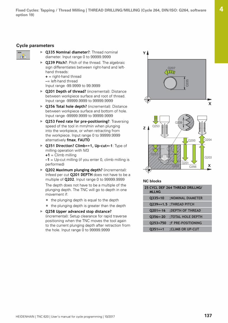
Fixed Cycles: Tapping / Thread Milling | THREAD DRILLING/MILLING (Cycle 264, DIN/ISO: G264, softwareoption 19)
4
HEIDENHAIN | TNC 620 | User’s manual for cycle programming | 10/2017 137
Cycle parametersQ335 Nominal diameter?: Thread nominaldiameter. Input range 0 to 99999.9999Q239 Pitch?: Pitch of the thread. The algebraicsign differentiates between right-hand and left-hand threads:+ = right-hand thread–= left-hand threadInput range -99.9999 to 99.9999Q201 Depth of thread? (incremental): Distancebetween workpiece surface and root of thread.Input range -99999.9999 to 99999.9999Q356 Total hole depth? (incremental): Distancebetween workpiece surface and bottom of hole.Input range -99999.9999 to 99999.9999Q253 Feed rate for pre-positioning?: Traversingspeed of the tool in mm/min when plunginginto the workpiece, or when retracting fromthe workpiece. Input range 0 to 99999.9999alternatively fmax, FAUTOQ351 Direction? Climb=+1, Up-cut=-1: Type ofmilling operation with M3+1 = Climb milling–1 = Up-cut milling (if you enter 0, climb milling isperformed)Q202 Maximum plunging depth? (incremental):Infeed per cut Q201 DEPTH does not have to be amultiple of Q202. Input range 0 to 99999.9999The depth does not have to be a multiple of theplunging depth. The TNC will go to depth in onemovement if:
the plunging depth is equal to the depththe plunging depth is greater than the depth
Q258 Upper advanced stop distance?(incremental): Setup clearance for rapid traversepositioning when the TNC moves the tool againto the current plunging depth after retraction fromthe hole. Input range 0 to 99999.9999
NC blocks
25 CYCL DEF 264 THREAD DRILLNG/MLLNG
Q335=10 ;NOMINAL DIAMETER
Q239=+1.5 ;THREAD PITCH
Q201=-16 ;DEPTH OF THREAD
Q356=-20 ;TOTAL HOLE DEPTH
Q253=750 ;F PRE-POSITIONING
Q351=+1 ;CLIMB OR UP-CUT

Fixed Cycles: Tapping / Thread Milling | THREAD DRILLING/MILLING (Cycle 264, DIN/ISO: G264, softwareoption 19)
4
138 HEIDENHAIN | TNC 620 | User’s manual for cycle programming | 10/2017
Q257 Infeed depth for chip breaking?(incremental): Plunging depth after which the TNCbreaks the chip. No chip breaking if 0 is entered.Input range 0 to 99999.9999Q256 Retract dist. for chip breaking?(incremental): Value by which the TNC retractsthe tool during chip breaking. Input range 0.000 to99999.999Q358 Sinking depth at front? (incremental):Distance between tool point and the top surfaceof the workpiece for countersinking at the front ofthe tool. Input range -99999.9999 to 99999.9999Q359 Countersinking offset at front?(incremental): Distance by which the TNC movesthe tool center away from the center. Input range0 to 99999.9999Q200 Set-up clearance? (incremental): Distancebetween tool tip and workpiece surface. Inputrange 0 to 99999.9999Q203 Workpiece surface coordinate? (absolute):Coordinate of the workpiece surface. Input range-99999.9999 to 99999.9999Q204 2nd set-up clearance? (incremental):Coordinate in the spindle axis at which no collisionbetween tool and workpiece (fixtures) can occur.Input range 0 to 99999.9999Q206 Feed rate for plunging?: Traversing speedof the tool in mm/min while plunging. Input range0 to 99999.999 alternatively FAUTO, fuQ207 Feed rate for milling?: Traversing speed ofthe tool in mm/min while milling. Input range 0 to99999.999 alternatively FAUTOQ512 Feed rate for approaching?: Traversingspeed of the tool in mm/min while approaching.For smaller thread diameters you can decreasethe approaching feed rate in order to reducethe danger of tool breakage. Input range 0 to99999.999 alternatively FAUTO
Q202=5 ;PLUNGING DEPTH
Q258=0.2 ;UPPER ADV STOP DIST
Q257=5 ;DEPTH FOR CHIP BRKNG
Q256=0.2 ;DIST FOR CHIP BRKNG
Q358=+0 ;DEPTH AT FRONT
Q359=+0 ;OFFSET AT FRONT
Q200=2 ;SET-UP CLEARANCE
Q203=+30 ;SURFACE COORDINATE
Q204=50 ;2ND SET-UP CLEARANCE
Q206=150 ;FEED RATE FOR PLNGNG
Q207=500 ;FEED RATE FOR MILLNG
Q512=0 ;FEED FOR APPROACH

Fixed Cycles: Tapping / Thread Milling | HELICAL THREAD DRILLING/MILLING (Cycle 265, DIN/ISO: G265,software option 19)
4
HEIDENHAIN | TNC 620 | User’s manual for cycle programming | 10/2017 139
4.9 HELICAL THREAD DRILLING/MILLING(Cycle 265, DIN/ISO: G265, softwareoption 19)
Cycle run1 The TNC positions the tool in the tool axis at rapid traverse
FMAX to the entered set-up clearance above the workpiecesurface.
Countersinking at front
2 If countersinking occurs before thread milling, the tool movesat the feed rate for countersinking to the sinking depth at front.If countersinking occurs after thread milling, the TNC movesthe tool to the countersinking depth at the feed rate for pre-positioning.
3 The TNC positions the tool without compensation from thecenter on a semicircle to the offset at front, and then follows acircular path at the feed rate for countersinking.
4 The tool then moves in a semicircle to the hole center.Thread milling
5 The tool moves at the programmed feed rate for pre-positioningto the starting plane for the thread.
6 The tool then approaches the thread diameter tangentially in ahelical movement.
7 The tool moves on a continuous helical downward path until itreaches the thread depth.
8 After that the tool departs the contour tangentially and returnsto the starting point in the working plane.
9 At the end of the cycle, the TNC retracts the tool in rapidtraverse to setup clearance or, if programmed, to the 2nd setupclearance.

Fixed Cycles: Tapping / Thread Milling | HELICAL THREAD DRILLING/MILLING (Cycle 265, DIN/ISO: G265,software option 19)
4
140 HEIDENHAIN | TNC 620 | User’s manual for cycle programming | 10/2017
Please note while programming:
Program a positioning block for the starting point (holecenter) in the working plane with radius compensationR0.The algebraic sign of the cycle parameters depthof thread or sinking depth at front determines theworking direction. The working direction is defined inthe following sequence:1. Thread depth2. Depth at frontIf you program a depth parameter to be 0, the TNC doesnot execute that step.If you change the thread depth, the TNC automaticallychanges the starting point for the helical movement.The type of milling (up-cut/climb) is determined by thethread (right-hand/left-hand) and the direction of toolrotation, since it is only possible to work in the directionof the tool.
NOTICEDanger of collision!
If you enter a positive depth with a cycle, the TNC reversescalculation of the pre-positioning. This means that the toolmoves at rapid traverse in the tool axis to set-up clearancebelow the workpiece surface!
Enter depth as negativeEnter in machine parameter displayDepthErr (No. 201003)whether the TNC should output an error message (on) or not(off) if a positive depth is entered

Fixed Cycles: Tapping / Thread Milling | HELICAL THREAD DRILLING/MILLING (Cycle 265, DIN/ISO: G265,software option 19)
4
HEIDENHAIN | TNC 620 | User’s manual for cycle programming | 10/2017 141
Cycle parametersQ335 Nominal diameter?: Thread nominaldiameter. Input range 0 to 99999.9999Q239 Pitch?: Pitch of the thread. The algebraicsign differentiates between right-hand and left-hand threads:+ = right-hand thread–= left-hand threadInput range -99.9999 to 99.9999Q201 Depth of thread? (incremental): Distancebetween workpiece surface and root of thread.Input range -99999.9999 to 99999.9999Q253 Feed rate for pre-positioning?: Traversingspeed of the tool in mm/min when plunginginto the workpiece, or when retracting fromthe workpiece. Input range 0 to 99999.9999alternatively fmax, FAUTOQ358 Sinking depth at front? (incremental):Distance between tool point and the top surfaceof the workpiece for countersinking at the front ofthe tool. Input range -99999.9999 to 99999.9999Q359 Countersinking offset at front?(incremental): Distance by which the TNC movesthe tool center away from the center. Input range0 to 99999.9999Q360 Countersink (before/after:0/1)? :Execution of chamfer0 = before thread milling1 = after thread millingQ200 Set-up clearance? (incremental): Distancebetween tool tip and workpiece surface. Inputrange 0 to 99999.9999Q203 Workpiece surface coordinate? (absolute):Coordinate of the workpiece surface. Input range-99999.9999 to 99999.9999

Fixed Cycles: Tapping / Thread Milling | HELICAL THREAD DRILLING/MILLING (Cycle 265, DIN/ISO: G265,software option 19)
4
142 HEIDENHAIN | TNC 620 | User’s manual for cycle programming | 10/2017
Q204 2nd set-up clearance? (incremental):Coordinate in the spindle axis at which no collisionbetween tool and workpiece (fixtures) can occur.Input range 0 to 99999.9999Q254 Feed rate for counterboring?: Traversingspeed of the tool in mm/min during counterboring.Input range 0 to 99999.9999 alternatively FAUTO,fuQ207 Feed rate for milling?: Traversing speed ofthe tool in mm/min while milling. Input range 0 to99999.999 alternatively FAUTO
NC blocks
25 CYCL DEF 265 HEL. THREAD DRLG/MLG
Q335=10 ;NOMINAL DIAMETER
Q239=+1.5 ;THREAD PITCH
Q201=-16 ;DEPTH OF THREAD
Q253=750 ;F PRE-POSITIONING
Q358=+0 ;DEPTH AT FRONT
Q359=+0 ;OFFSET AT FRONT
Q360=0 ;COUNTERSINK PROCESS
Q200=2 ;SET-UP CLEARANCE
Q203=+30 ;SURFACE COORDINATE
Q204=50 ;2ND SET-UP CLEARANCE
Q254=150 ;F COUNTERBORING
Q207=500 ;FEED RATE FOR MILLNG

Fixed Cycles: Tapping / Thread Milling | OUTSIDE THREAD MILLING (Cycle 267, DIN/ISO: G267, softwareoption 19)
4
HEIDENHAIN | TNC 620 | User’s manual for cycle programming | 10/2017 143
4.10 OUTSIDE THREAD MILLING (Cycle 267,DIN/ISO: G267, software option 19)
Cycle run1 The TNC positions the tool in the tool axis at rapid traverse
FMAX to the entered set-up clearance above the workpiecesurface.
Countersinking at front
2 The TNC moves on the reference axis of the working plane fromthe center of the stud to the starting point for countersinkingat front. The position of the starting point is determined by thethread radius, tool radius and pitch.
3 The tool moves at the feed rate for pre-positioning to the sinkingdepth at front.
4 The TNC positions the tool without compensation from thecenter on a semicircle to the offset at front, and then follows acircular path at the feed rate for countersinking.
5 The tool then moves in a semicircle to the starting point.Thread milling
6 The TNC positions the tool to the starting point if there hasbeen no previous countersinking at front. Starting point forthread milling = starting point for countersinking at front.
7 The tool moves at the programmed feed rate for pre-positioningto the starting plane. The starting plane is derived from thealgebraic sign of the thread pitch, the milling method (climb orup-cut milling) and the number of threads per step.
8 The tool then approaches the thread diameter tangentially in ahelical movement.
9 Depending on the setting of the parameter for the number ofthreads, the tool mills the thread in one helical movement, inseveral offset helical movements or in one continuous helicalmovement.
10 After that the tool departs the contour tangentially and returnsto the starting point in the working plane.
11 At the end of the cycle, the TNC retracts the tool in rapidtraverse to setup clearance or, if programmed, to the 2nd setupclearance.

Fixed Cycles: Tapping / Thread Milling | OUTSIDE THREAD MILLING (Cycle 267, DIN/ISO: G267, softwareoption 19)
4
144 HEIDENHAIN | TNC 620 | User’s manual for cycle programming | 10/2017
Please note while programming:
Program a positioning block for the starting point (studcenter) in the working plane with radius compensationR0.The offset required before countersinking at the frontshould be determined ahead of time. You must enterthe value from the center of the stud to the center ofthe tool (uncorrected value).The algebraic sign of the cycle parameters depthof thread or sinking depth at front determines theworking direction. The working direction is defined inthe following sequence:1. Thread depth2. Depth at frontIf you program a depth parameter to be 0, the TNC doesnot execute that step.The algebraic sign for the cycle parameter "thread depth"determines the working direction.
NOTICEDanger of collision!
If you enter a positive depth with a cycle, the TNC reversescalculation of the pre-positioning. This means that the toolmoves at rapid traverse in the tool axis to set-up clearancebelow the workpiece surface!
Enter depth as negativeEnter in machine parameter displayDepthErr (No. 201003)whether the TNC should output an error message (on) or not(off) if a positive depth is entered
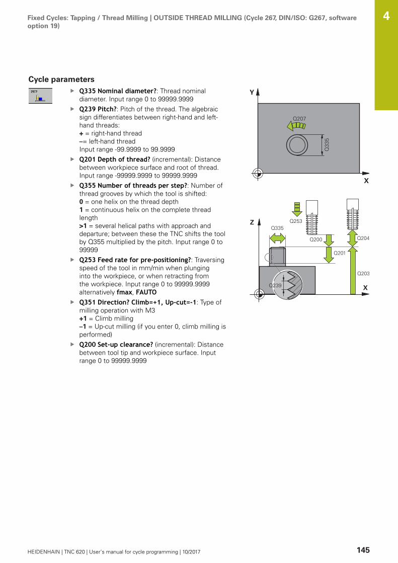
Fixed Cycles: Tapping / Thread Milling | OUTSIDE THREAD MILLING (Cycle 267, DIN/ISO: G267, softwareoption 19)
4
HEIDENHAIN | TNC 620 | User’s manual for cycle programming | 10/2017 145
Cycle parametersQ335 Nominal diameter?: Thread nominaldiameter. Input range 0 to 99999.9999Q239 Pitch?: Pitch of the thread. The algebraicsign differentiates between right-hand and left-hand threads:+ = right-hand thread–= left-hand threadInput range -99.9999 to 99.9999Q201 Depth of thread? (incremental): Distancebetween workpiece surface and root of thread.Input range -99999.9999 to 99999.9999Q355 Number of threads per step?: Number ofthread grooves by which the tool is shifted:0 = one helix on the thread depth 1 = continuous helix on the complete threadlength >1 = several helical paths with approach anddeparture; between these the TNC shifts the toolby Q355 multiplied by the pitch. Input range 0 to99999Q253 Feed rate for pre-positioning?: Traversingspeed of the tool in mm/min when plunginginto the workpiece, or when retracting fromthe workpiece. Input range 0 to 99999.9999alternatively fmax, FAUTOQ351 Direction? Climb=+1, Up-cut=-1: Type ofmilling operation with M3+1 = Climb milling–1 = Up-cut milling (if you enter 0, climb milling isperformed)Q200 Set-up clearance? (incremental): Distancebetween tool tip and workpiece surface. Inputrange 0 to 99999.9999

Fixed Cycles: Tapping / Thread Milling | OUTSIDE THREAD MILLING (Cycle 267, DIN/ISO: G267, softwareoption 19)
4
146 HEIDENHAIN | TNC 620 | User’s manual for cycle programming | 10/2017
Q358 Sinking depth at front? (incremental):Distance between tool point and the top surfaceof the workpiece for countersinking at the front ofthe tool. Input range -99999.9999 to 99999.9999Q359 Countersinking offset at front?(incremental): Distance by which the TNC movesthe tool center away from the center. Input range0 to 99999.9999Q203 Workpiece surface coordinate? (absolute):Coordinate of the workpiece surface. Input range-99999.9999 to 99999.9999Q204 2nd set-up clearance? (incremental):Coordinate in the spindle axis at which no collisionbetween tool and workpiece (fixtures) can occur.Input range 0 to 99999.9999Q254 Feed rate for counterboring?: Traversingspeed of the tool in mm/min during counterboring.Input range 0 to 99999.9999 alternatively FAUTO,fuQ207 Feed rate for milling?: Traversing speed ofthe tool in mm/min while milling. Input range 0 to99999.999 alternatively FAUTOQ512 Feed rate for approaching?: Traversingspeed of the tool in mm/min while approaching.For smaller thread diameters you can decreasethe approaching feed rate in order to reducethe danger of tool breakage. Input range 0 to99999.999 alternatively FAUTO
NC blocks
25 CYCL DEF 267 OUTSIDE THREADMLLNG
Q335=10 ;NOMINAL DIAMETER
Q239=+1.5 ;THREAD PITCH
Q201=-20 ;DEPTH OF THREAD
Q355=0 ;THREADS PER STEP
Q253=750 ;F PRE-POSITIONING
Q351=+1 ;CLIMB OR UP-CUT
Q200=2 ;SET-UP CLEARANCE
Q358=+0 ;DEPTH AT FRONT
Q359=+0 ;OFFSET AT FRONT
Q203=+30 ;SURFACE COORDINATE
Q204=50 ;2ND SET-UP CLEARANCE
Q254=150 ;F COUNTERBORING
Q207=500 ;FEED RATE FOR MILLNG
Q512=0 ;FEED FOR APPROACH
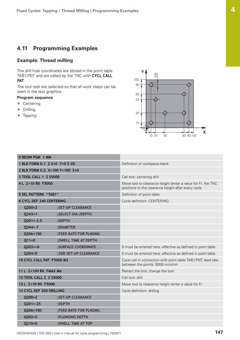
Fixed Cycles: Tapping / Thread Milling | Programming Examples 4
HEIDENHAIN | TNC 620 | User’s manual for cycle programming | 10/2017 147
4.11 Programming Examples
Example: Thread milling
The drill hole coordinates are stored in the point tableTAB1.PNT and are called by the TNC with CYCL CALLPAT.The tool radii are selected so that all work steps can beseen in the test graphics.Program sequence
CenteringDrillingTapping
0 BEGIN PGM 1 MM
1 BLK FORM 0.1 Z X+0 Y+0 Z-20 Definition of workpiece blank
2 BLK FORM 0.2 X+100 Y+100 Z+0
3 TOOL CALL 1 Z S5000 Call tool: centering drill
4 L Z+10 R0 F5000 Move tool to clearance height (enter a value for F): the TNCpositions to the clearance height after every cycle
5 SEL PATTERN “TAB1“ Definition of point table
6 CYCL DEF 240 CENTERING Cycle definition: CENTERING
Q200=2 ;SET-UP CLEARANCE
Q343=1 ;SELECT DIA./DEPTH
Q201=-3.5 ;DEPTH
Q344=-7 ;DIAMETER
Q206=150 ;FEED RATE FOR PLNGNG
Q11=0 ;DWELL TIME AT DEPTH
Q203=+0 ;SURFACE COORDINATE 0 must be entered here, effective as defined in point table
Q204=0 ;2ND SET-UP CLEARANCE 0 must be entered here, effective as defined in point table
10 CYCL CALL PAT F5000 M3 Cycle call in connection with point table TAB1.PNT, feed ratebetween the points: 5000 mm/min
11 L Z+100 R0 FMAX M6 Retract the tool, change the tool
12 TOOL CALL 2 Z S5000 Call tool: drill
13 L Z+10 R0 F5000 Move tool to clearance height (enter a value for F)
14 CYCL DEF 200 DRILLING Cycle definition: drilling
Q200=2 ;SET-UP CLEARANCE
Q201=-25 ;DEPTH
Q206=150 ;FEED RATE FOR PLNGNG
Q202=5 ;PLUNGING DEPTH
Q210=0 ;DWELL TIME AT TOP
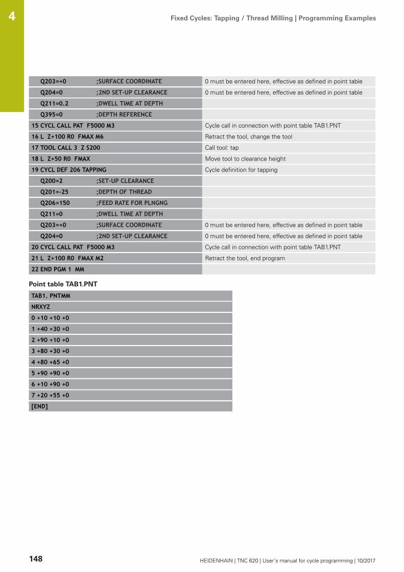
Fixed Cycles: Tapping / Thread Milling | Programming Examples 4
148 HEIDENHAIN | TNC 620 | User’s manual for cycle programming | 10/2017
Q203=+0 ;SURFACE COORDINATE 0 must be entered here, effective as defined in point table
Q204=0 ;2ND SET-UP CLEARANCE 0 must be entered here, effective as defined in point table
Q211=0.2 ;DWELL TIME AT DEPTH
Q395=0 ;DEPTH REFERENCE
15 CYCL CALL PAT F5000 M3 Cycle call in connection with point table TAB1.PNT
16 L Z+100 R0 FMAX M6 Retract the tool, change the tool
17 TOOL CALL 3 Z S200 Call tool: tap
18 L Z+50 R0 FMAX Move tool to clearance height
19 CYCL DEF 206 TAPPING Cycle definition for tapping
Q200=2 ;SET-UP CLEARANCE
Q201=-25 ;DEPTH OF THREAD
Q206=150 ;FEED RATE FOR PLNGNG
Q211=0 ;DWELL TIME AT DEPTH
Q203=+0 ;SURFACE COORDINATE 0 must be entered here, effective as defined in point table
Q204=0 ;2ND SET-UP CLEARANCE 0 must be entered here, effective as defined in point table
20 CYCL CALL PAT F5000 M3 Cycle call in connection with point table TAB1.PNT
21 L Z+100 R0 FMAX M2 Retract the tool, end program
22 END PGM 1 MM
Point table TAB1.PNT
TAB1. PNTMM
NRXYZ
0 +10 +10 +0
1 +40 +30 +0
2 +90 +10 +0
3 +80 +30 +0
4 +80 +65 +0
5 +90 +90 +0
6 +10 +90 +0
7 +20 +55 +0
[END]
5Fixed Cycles:
Pocket Milling /Stud Milling /
Slot Milling

Fixed Cycles: Pocket Milling / Stud Milling / Slot Milling | Fundamentals 5
150 HEIDENHAIN | TNC 620 | User’s manual for cycle programming | 10/2017
5.1 Fundamentals
OverviewThe TNC offers the following cycles for machining pockets, studsand slots:
Soft key Cycle Page
251 RECTANGULAR POCKET Roughing/finishing cycle withselection of machining opera-tion and helical plunging
151
252 CIRCULAR POCKET Roughing/finishing cycle withselection of machining opera-tion and helical plunging
156
253 SLOT MILLING Roughing/finishing cycle withselection of machining opera-tion and reciprocal plunging
162
254 CIRCULAR SLOT Roughing/finishing cycle withselection of machining opera-tion and reciprocal plunging
166
256 RECTANGULAR STUD Roughing/finishing cycle withstepover, if multiple passes arerequired
172
257 CIRCULAR STUD Roughing/finishing cycle withstepover, if multiple passes arerequired
177
233 FACE MILLING Machining the face with up to3 limits
186

Fixed Cycles: Pocket Milling / Stud Milling / Slot Milling | RECTANGULAR POCKET (Cycle 251, DIN/ISO:G251, software option 19)
5
HEIDENHAIN | TNC 620 | User’s manual for cycle programming | 10/2017 151
5.2 RECTANGULAR POCKET (Cycle 251,DIN/ISO: G251, software option 19)
Cycle runUse Cycle 251 RECTANGULAR POCKET to completely machinerectangular pockets. Depending on the cycle parameters, thefollowing machining alternatives are available:
Complete machining: Roughing, floor finishing, side finishingOnly roughingOnly floor finishing and side finishingOnly floor finishingOnly side finishing
Roughing
1 The tool plunges the workpiece at the pocket center andadvances to the first plunging depth. Specify the plungingstrategy with parameter Q366.
2 The TNC roughs out the pocket from the inside out, takingthe path overlap (parameter Q370) and the finishing allowance(parameters Q368 and Q369) into account.
3 At the end of the roughing operation, the TNC moves the tooltangentially away from the pocket wall, then moves by the set-up clearance above the current pecking depth and returns fromthere at rapid traverse to the pocket center.
4 This process is repeated until the programmed pocket depth isreached.
Finishing
5 If finishing allowances have been defined, the TNC plunges andthen approaches the contour. The approach movement occurson a radius in order to ensure that a gentle approach is possible.The TNC first finishes the pocket walls, in multiple infeeds if sospecified.
6 Then the TNC finishes the floor of the pocket from the insideout. The pocket floor is approached tangentially.

Fixed Cycles: Pocket Milling / Stud Milling / Slot Milling | RECTANGULAR POCKET (Cycle 251, DIN/ISO:G251, software option 19)
5
152 HEIDENHAIN | TNC 620 | User’s manual for cycle programming | 10/2017
Please note while programming:
With an inactive tool table you must always plungevertically (Q366=0) because you cannot define aplunging angle.Pre-position the tool in the machining plane to thestarting position with radius compensation R0. Noteparameter Q367 (position).The TNC automatically pre-positions the tool in the toolaxis. Observe Q204 2ND SET-UP CLEARANCE.The algebraic sign for the cycle parameter DEPTHdetermines the working direction. If you programDEPTH=0, the cycle will not be executed.At the end of the cycle, the TNC returns the tool to thestarting position.At the end of a roughing operation, the TNC positionsthe tool back to the pocket center at rapid traverse. Thetool is above the current pecking depth by the set-upclearance. Enter the set-up clearance so that the toolcannot jam because of chips.The TNC outputs an error message during helicalplunging if the internally calculated diameter of the helixis smaller than twice the tool diameter. If you are usinga center-cut tool, you can switch off this monitoringfunction via the suppressPlungeErr machine parameter(No. 201006).The TNC reduces the infeed depth to the LCUTS toollength defined in the tool table if the tool length isshorter than the Q202 infeed depth programmed in thecycle.
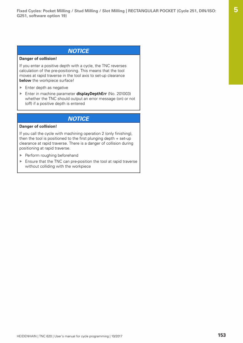
Fixed Cycles: Pocket Milling / Stud Milling / Slot Milling | RECTANGULAR POCKET (Cycle 251, DIN/ISO:G251, software option 19)
5
HEIDENHAIN | TNC 620 | User’s manual for cycle programming | 10/2017 153
NOTICEDanger of collision!
If you enter a positive depth with a cycle, the TNC reversescalculation of the pre-positioning. This means that the toolmoves at rapid traverse in the tool axis to set-up clearancebelow the workpiece surface!
Enter depth as negativeEnter in machine parameter displayDepthErr (No. 201003)whether the TNC should output an error message (on) or not(off) if a positive depth is entered
NOTICEDanger of collision!
If you call the cycle with machining operation 2 (only finishing),then the tool is positioned to the first plunging depth + set-upclearance at rapid traverse. There is a danger of collision duringpositioning at rapid traverse.
Perform roughing beforehandEnsure that the TNC can pre-position the tool at rapid traversewithout colliding with the workpiece

Fixed Cycles: Pocket Milling / Stud Milling / Slot Milling | RECTANGULAR POCKET (Cycle 251, DIN/ISO:G251, software option 19)
5
154 HEIDENHAIN | TNC 620 | User’s manual for cycle programming | 10/2017
Cycle parametersQ215 Machining operation (0/1/2)?: Definemachining operation:0: Roughing and finishing1: Only roughing2: Only finishing Side finishing and floor finishing are only machinedwhen the specific allowance (Q368, Q369) isdefinedQ218 First side length? (incremental): Pocketlength, parallel to the reference axis of the workingplane. Input range 0 to 99999.9999Q219 Second side length? (incremental): Pocketlength, parallel to the minor axis of the workingplane. Input range 0 to 99999.9999Q220 Corner radius?: Radius of the pocket corner.If you have entered 0 here, the TNC assumes thatthe corner radius is equal to the tool radius. Inputrange 0 to 99999.9999Q368 Finishing allowance for side? (incremental):Finishing allowance in the machining plane. Inputrange 0 to 99999.9999Q224 Angle of rotation? (absolute): Angle bywhich the entire machining is rotated. The centerof rotation is the position at which the tool islocated when the cycle is called. Input range-360.0000 to 360.0000Q367 Position of pocket (0/1/2/3/4)?: Position ofthe pocket in reference to the position of the toolwhen the cycle is called:0: Tool position = pocket center1: Tool position = left corner below 2: Tool position = right corner below3: Tool position = right corner top 4: Tool position = left corner topQ207 Feed rate for milling?: Traversing speed ofthe tool in mm/min while milling. Input range 0 to99999.999 alternatively FAUTO, fu, FZQ351 Direction? Climb=+1, Up-cut=-1: Type ofmilling operation with M3:+1 = Climb–1 = Up-cutPREDEF: The TNC uses the value from theGLOBAL DEF block (if you enter 0, climb milling isperformed)Q201 Depth? (incremental): Distance betweenworkpiece surface and bottom of pocket. Inputrange -99999.9999 to 99999.9999Q202 Plunging depth? (incremental): Infeed percut; enter a value greater than 0. Input range 0 to99999.9999Q369 Finishing allowance for floor?(incremental): Finishing allowance for the floor.Input range 0 to 99999.9999
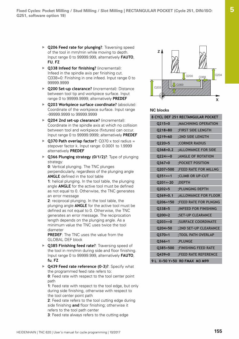
Fixed Cycles: Pocket Milling / Stud Milling / Slot Milling | RECTANGULAR POCKET (Cycle 251, DIN/ISO:G251, software option 19)
5
HEIDENHAIN | TNC 620 | User’s manual for cycle programming | 10/2017 155
Q206 Feed rate for plunging?: Traversing speedof the tool in mm/min while moving to depth.Input range 0 to 99999.999, alternatively FAUTO,FU, FZQ338 Infeed for finishing? (incremental):Infeed in the spindle axis per finishing cut.Q338=0: Finishing in one infeed. Input range 0 to99999.9999Q200 Set-up clearance? (incremental): Distancebetween tool tip and workpiece surface. Inputrange 0 to 99999.9999; alternatively PREDEFQ203 Workpiece surface coordinate? (absolute):Coordinate of the workpiece surface. Input range-99999.9999 to 99999.9999Q204 2nd set-up clearance? (incremental):Coordinate in the spindle axis at which no collisionbetween tool and workpiece (fixtures) can occur.Input range 0 to 99999.9999; alternatively PREDEFQ370 Path overlap factor?: Q370 x tool radius =stepover factor k. Input range: 0.0001 to 1.9999alternatively PREDEFQ366 Plunging strategy (0/1/2)?: Type of plungingstrategy:0: Vertical plunging. The TNC plungesperpendicularly, regardless of the plunging angleANGLE defined in the tool table1: helical plunging. In the tool table, the plungingangle ANGLE for the active tool must be definedas not equal to 0. Otherwise, the TNC generatesan error message2: reciprocal plunging. In the tool table, theplunging angle ANGLE for the active tool must bedefined as not equal to 0. Otherwise, the TNCgenerates an error message. The reciprocationlength depends on the plunging angle. As aminimum value the TNC uses twice the tooldiameterPREDEF: The TNC uses the value from theGLOBAL DEF blockQ385 Finishing feed rate?: Traversing speed ofthe tool in mm/min during side and floor finishing.Input range 0 to 99999.999, alternatively FAUTO,fu, FZQ439 Feed rate reference (0-3)?: Specify whatthe programmed feed rate refers to:0: Feed rate with respect to the tool center pointpath1: Feed rate with respect to the tool edge, but onlyduring side finishing, otherwise with respect tothe tool center point path2: Feed rate refers to the tool cutting edge duringside finishing and floor finishing; otherwise itrefers to the tool path center3: Feed rate always refers to the cutting edge
NC blocks
8 CYCL DEF 251 RECTANGULAR POCKET
Q215=0 ;MACHINING OPERATION
Q218=80 ;FIRST SIDE LENGTH
Q219=60 ;2ND SIDE LENGTH
Q220=5 ;CORNER RADIUS
Q368=0.2 ;ALLOWANCE FOR SIDE
Q224=+0 ;ANGLE OF ROTATION
Q367=0 ;POCKET POSITION
Q207=500 ;FEED RATE FOR MILLNG
Q351=+1 ;CLIMB OR UP-CUT
Q201=-20 ;DEPTH
Q202=5 ;PLUNGING DEPTH
Q369=0.1 ;ALLOWANCE FOR FLOOR
Q206=150 ;FEED RATE FOR PLNGNG
Q338=5 ;INFEED FOR FINISHING
Q200=2 ;SET-UP CLEARANCE
Q203=+0 ;SURFACE COORDINATE
Q204=50 ;2ND SET-UP CLEARANCE
Q370=1 ;TOOL PATH OVERLAP
Q366=1 ;PLUNGE
Q385=500 ;FINISHING FEED RATE
Q439=0 ;FEED RATE REFERENCE
9 L X+50 Y+50 R0 FMAX M3 M99

Fixed Cycles: Pocket Milling / Stud Milling / Slot Milling | CIRCULAR POCKET (Cycle 252, DIN/ISO: G252,software option 19)
5
156 HEIDENHAIN | TNC 620 | User’s manual for cycle programming | 10/2017
5.3 CIRCULAR POCKET (Cycle 252, DIN/ISO:G252, software option 19)
Cycle runUse Cycle 252 CIRCULAR POCKET to machine circular pockets.Depending on the cycle parameters, the following machiningalternatives are available:
Complete machining: Roughing, floor finishing, side finishingOnly roughingOnly floor finishing and side finishingOnly floor finishingOnly side finishing
Roughing
1 The TNC first moves the tool at rapid traverse to the set-upclearance Q200 above the workpiece.
2 The tool plunges to the first plunging depth at the pocket center.Specify the plunging strategy with parameter Q366.
3 The TNC roughs out the pocket from the inside out, takingthe path overlap (parameter Q370) and the finishing allowance(parameters Q368 and Q369) into account.
4 At the end of a roughing operation, the TNC moves the tooltangentially away from the pocket wall by the set-up clearanceQ200 in the working plane, then retracts the tool by Q200 atrapid traverse and returns it from there at rapid traverse to thepocket center.
5 Steps 2 to 4 are repeated until the programmed pocket depth isreached, taking the finishing allowance Q369 into account.
6 If only roughing was programmed (Q215=1) the tool movesaway from the pocket wall tangentially by the set-up clearanceQ200, then retracts at rapid traverse to the 2nd set-up clearanceQ204 in the tool axis and returns at rapid traverse to the pocketcenter

Fixed Cycles: Pocket Milling / Stud Milling / Slot Milling | CIRCULAR POCKET (Cycle 252, DIN/ISO: G252,software option 19)
5
HEIDENHAIN | TNC 620 | User’s manual for cycle programming | 10/2017 157
Finishing
1 Inasmuch as finishing allowances are defined, the TNC thenfinishes the pocket walls, in multiple infeeds if so specified.
2 The TNC positions the tool in the tool axis in front of thepocket wall, taking the finishing allowance Q368 and the set-upclearance Q200 into account.
3 The TNC clears the pocket from the inside out until the diameterQ223 is reached.
4 Then the TNC again positions the tool in the tool axis in frontof the pocket wall, taking the finishing allowance Q368 and theset-up clearance Q200 into account, and repeats the finishingprocess of the pocket wall at the next depth.
5 The TNC repeats this process until the programmed diameter isreached.
6 After machining to the diameter Q223, the TNC retracts thetool tangentially by the finishing allowance Q368 plus the set-up clearance Q200 in the working plane, then retracts at rapidtraverse to the set-up clearance Q200 in the tool axis andreturns to the pocket center.
7 Next, the TNC moves the tool in the tool axis to the depth Q201and finishes the floor of the pocket from the inside out. Thepocket floor is approached tangentially.
8 The TNC repeats this process until the depth Q201 plus Q369 isreached.
9 Finally, the tool moves away from the pocket wall tangentiallyby the set-up clearance Q200, then retracts at rapid traverse tothe set-up clearance Q200 in the tool axis and returns at rapidtraverse to the pocket center.

Fixed Cycles: Pocket Milling / Stud Milling / Slot Milling | CIRCULAR POCKET (Cycle 252, DIN/ISO: G252,software option 19)
5
158 HEIDENHAIN | TNC 620 | User’s manual for cycle programming | 10/2017
Please note while programming:
With an inactive tool table you must always plungevertically (Q366=0) because you cannot define aplunging angle.Pre-position the tool in the machining plane tothe starting position (circle center) with radiuscompensation R0.The TNC automatically pre-positions the tool in the toolaxis. Observe Q204 2ND SET-UP CLEARANCE.The algebraic sign for the cycle parameter DEPTHdetermines the working direction. If you programDEPTH=0, the cycle will not be executed.At the end of the cycle, the TNC returns the tool to thestarting position.At the end of a roughing operation, the TNC positionsthe tool back to the pocket center at rapid traverse. Thetool is above the current pecking depth by the set-upclearance. Enter the set-up clearance so that the toolcannot jam because of chips.The TNC outputs an error message during helicalplunging if the internally calculated diameter of the helixis smaller than twice the tool diameter. If you are usinga center-cut tool, you can switch off this monitoringfunction via the suppressPlungeErr machine parameter(No. 201006).The TNC reduces the infeed depth to the LCUTS toollength defined in the tool table if the tool length isshorter than the Q202 infeed depth programmed in thecycle.

Fixed Cycles: Pocket Milling / Stud Milling / Slot Milling | CIRCULAR POCKET (Cycle 252, DIN/ISO: G252,software option 19)
5
HEIDENHAIN | TNC 620 | User’s manual for cycle programming | 10/2017 159
NOTICEDanger of collision!
If you enter a positive depth with a cycle, the TNC reversescalculation of the pre-positioning. This means that the toolmoves at rapid traverse in the tool axis to set-up clearancebelow the workpiece surface!
Enter depth as negativeEnter in machine parameter displayDepthErr (No. 201003)whether the TNC should output an error message (on) or not(off) if a positive depth is entered
NOTICEDanger of collision!
If you call the cycle with machining operation 2 (only finishing),then the tool is positioned to the first plunging depth + set-upclearance at rapid traverse. There is a danger of collision duringpositioning at rapid traverse.
Perform roughing beforehandEnsure that the TNC can pre-position the tool at rapid traversewithout colliding with the workpiece

Fixed Cycles: Pocket Milling / Stud Milling / Slot Milling | CIRCULAR POCKET (Cycle 252, DIN/ISO: G252,software option 19)
5
160 HEIDENHAIN | TNC 620 | User’s manual for cycle programming | 10/2017
Cycle parametersQ215 Machining operation (0/1/2)?: Definemachining operation:0: Roughing and finishing1: Only roughing2: Only finishing Side finishing and floor finishing are only machinedwhen the specific allowance (Q368, Q369) isdefinedQ223 Circle diameter?: Diameter of the finishedpocket. Input range 0 to 99999.9999Q368 Finishing allowance for side? (incremental):Finishing allowance in the machining plane. Inputrange 0 to 99999.9999Q207 Feed rate for milling?: Traversing speed ofthe tool in mm/min while milling. Input range 0 to99999.999 alternatively FAUTO, fu, FZQ351 Direction? Climb=+1, Up-cut=-1: Type ofmilling operation with M3:+1 = Climb–1 = Up-cutPREDEF: The TNC uses the value from theGLOBAL DEF block (if you enter 0, climb milling isperformed)Q201 Depth? (incremental): Distance betweenworkpiece surface and bottom of pocket. Inputrange -99999.9999 to 99999.9999Q202 Plunging depth? (incremental): Infeed percut; enter a value greater than 0. Input range 0 to99999.9999Q369 Finishing allowance for floor?(incremental): Finishing allowance for the floor.Input range 0 to 99999.9999Q206 Feed rate for plunging?: Traversing speedof the tool in mm/min while moving to depth.Input range 0 to 99999.999, alternatively FAUTO,FU, FZ

Fixed Cycles: Pocket Milling / Stud Milling / Slot Milling | CIRCULAR POCKET (Cycle 252, DIN/ISO: G252,software option 19)
5
HEIDENHAIN | TNC 620 | User’s manual for cycle programming | 10/2017 161
Q338 Infeed for finishing? (incremental):Infeed in the spindle axis per finishing cut.Q338=0: Finishing in one infeed. Input range 0 to99999.9999Q200 Set-up clearance? (incremental): Distancebetween tool tip and workpiece surface. Inputrange 0 to 99999.9999; alternatively PREDEFQ203 Workpiece surface coordinate? (absolute):Coordinate of the workpiece surface. Input range-99999.9999 to 99999.9999Q204 2nd set-up clearance? (incremental):Coordinate in the spindle axis at which no collisionbetween tool and workpiece (fixtures) can occur.Input range 0 to 99999.9999; alternatively PREDEFQ370 Path overlap factor?: Q370 x tool radius =stepover factor k. The overlapping is consideredas maximum overlapping. The overlapping can bereduced to avoid residual material at the corners.Input range 0.1 to 1.9999; alternatively PREDEFQ366 Plunging strategy (0/1)?: Type of plungingstrategy:
0 = vertical plunging. In the tool table, theplunging angle ANGLE for the active tool mustbe defined as 0 or 90. The TNC will otherwisedisplay an error message.1 = helical plunging. In the tool table, theplunging angle ANGLE for the active tool mustbe defined as not equal to 0. The TNC willotherwise display an error message.Alternative: PREDEF
Q385 Finishing feed rate?: Traversing speed ofthe tool in mm/min during side and floor finishing.Input range 0 to 99999.999, alternatively FAUTO,fu, FZQ439 Feed rate reference (0-3)?: Specify whatthe programmed feed rate refers to:0: Feed rate with respect to the tool center pointpath1: Feed rate with respect to the tool edge, but onlyduring side finishing, otherwise with respect tothe tool center point path2: Feed rate refers to the tool cutting edge duringside finishing and floor finishing; otherwise itrefers to the tool path center3: Feed rate always refers to the cutting edge
NC blocks
8 CYCL DEF 252 CIRCULAR POCKET
Q215=0 ;MACHINING OPERATION
Q223=60 ;CIRCLE DIAMETER
Q368=0.2 ;ALLOWANCE FOR SIDE
Q207=500 ;FEED RATE FOR MILLNG
Q351=+1 ;CLIMB OR UP-CUT
Q201=-20 ;DEPTH
Q202=5 ;PLUNGING DEPTH
Q369=0.1 ;ALLOWANCE FOR FLOOR
Q206=150 ;FEED RATE FOR PLNGNG
Q338=5 ;INFEED FOR FINISHING
Q200=2 ;SET-UP CLEARANCE
Q203=+0 ;SURFACE COORDINATE
Q204=50 ;2ND SET-UP CLEARANCE
Q370=1 ;TOOL PATH OVERLAP
Q366=1 ;PLUNGE
Q385=500 ;FINISHING FEED RATE
Q439=3 ;FEED RATE REFERENCE
9 L X+50 Y+50 R0 FMAX M3 M99

Fixed Cycles: Pocket Milling / Stud Milling / Slot Milling | SLOT MILLING (Cycle 253, DIN/ISO: G253),Software Option 19
5
162 HEIDENHAIN | TNC 620 | User’s manual for cycle programming | 10/2017
5.4 SLOT MILLING (Cycle 253, DIN/ISO:G253), Software Option 19
Cycle runUse Cycle 253 to completely machine a slot. Depending on thecycle parameters, the following machining alternatives are available:
Complete machining: Roughing, floor finishing, side finishingOnly roughingOnly floor finishing and side finishingOnly floor finishingOnly side finishing
Roughing
1 Starting from the left slot arc center, the tool moves in areciprocating motion at the plunging angle defined in the tooltable to the first infeed depth. Specify the plunging strategywith parameter Q366.
2 The TNC roughs out the slot from the inside out, taking thefinishing allowances (parameter Q368) into account.
3 The TNC retracts the tool by the set-up clearance Q200. If theslot width matches the cutter diameter, the TNC retracts thetool from the slot after each infeed.
4 This process is repeated until the programmed slot depth isreached.
Finishing
5 Inasmuch as finishing allowances are defined, the TNC thenfinishes the slot walls, in multiple infeeds if so specified. Theslot side is approached tangentially in the left slot arc.
6 Then the TNC finishes the floor of the slot from the inside out.

Fixed Cycles: Pocket Milling / Stud Milling / Slot Milling | SLOT MILLING (Cycle 253, DIN/ISO: G253),Software Option 19
5
HEIDENHAIN | TNC 620 | User’s manual for cycle programming | 10/2017 163
Please note while programming:
With an inactive tool table you must always plungevertically (Q366=0) because you cannot define aplunging angle.Pre-position the tool in the machining plane to thestarting position with radius compensation R0. Noteparameter Q367 (position).The TNC automatically pre-positions the tool in the toolaxis. Observe Q204 2ND SET-UP CLEARANCE.
The algebraic sign for the cycle parameter DEPTHdetermines the working direction. If you programDEPTH=0, the cycle will not be executed.If the slot width is greater than twice the tool diameter,the TNC roughs the slot correspondingly from the insideout. You can therefore mill any slots with small tools,too.The TNC reduces the infeed depth to the LCUTS toollength defined in the tool table if the tool length isshorter than the Q202 infeed depth programmed in thecycle.
NOTICEDanger of collision!
If you enter a positive depth with a cycle, the TNC reversescalculation of the pre-positioning. This means that the toolmoves at rapid traverse in the tool axis to set-up clearancebelow the workpiece surface!
Enter depth as negativeEnter in machine parameter displayDepthErr (No. 201003)whether the TNC should output an error message (on) or not(off) if a positive depth is entered
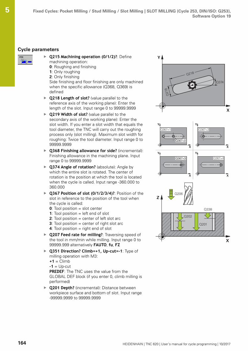
Fixed Cycles: Pocket Milling / Stud Milling / Slot Milling | SLOT MILLING (Cycle 253, DIN/ISO: G253),Software Option 19
5
164 HEIDENHAIN | TNC 620 | User’s manual for cycle programming | 10/2017
Cycle parametersQ215 Machining operation (0/1/2)?: Definemachining operation:0: Roughing and finishing1: Only roughing2: Only finishing Side finishing and floor finishing are only machinedwhen the specific allowance (Q368, Q369) isdefinedQ218 Length of slot? (value parallel to thereference axis of the working plane): Enter thelength of the slot. Input range 0 to 99999.9999Q219 Width of slot? (value parallel to thesecondary axis of the working plane): Enter theslot width. If you enter a slot width that equals thetool diameter, the TNC will carry out the roughingprocess only (slot milling). Maximum slot width forroughing: Twice the tool diameter. Input range 0 to99999.9999Q368 Finishing allowance for side? (incremental):Finishing allowance in the machining plane. Inputrange 0 to 99999.9999Q374 Angle of rotation? (absolute): Angle bywhich the entire slot is rotated. The center ofrotation is the position at which the tool is locatedwhen the cycle is called. Input range -360.000 to360.000Q367 Position of slot (0/1/2/3/4)?: Position of theslot in reference to the position of the tool whenthe cycle is called:0: Tool position = slot center1: Tool position = left end of slot2: Tool position = center of left slot arc3: Tool position = center of right slot arc4: Tool position = right end of slotQ207 Feed rate for milling?: Traversing speed ofthe tool in mm/min while milling. Input range 0 to99999.999 alternatively FAUTO, fu, FZQ351 Direction? Climb=+1, Up-cut=-1: Type ofmilling operation with M3:+1 = Climb–1 = Up-cutPREDEF: The TNC uses the value from theGLOBAL DEF block (if you enter 0, climb milling isperformed)Q201 Depth? (incremental): Distance betweenworkpiece surface and bottom of slot. Input range-99999.9999 to 99999.9999

Fixed Cycles: Pocket Milling / Stud Milling / Slot Milling | SLOT MILLING (Cycle 253, DIN/ISO: G253),Software Option 19
5
HEIDENHAIN | TNC 620 | User’s manual for cycle programming | 10/2017 165
Q202 Plunging depth? (incremental): Infeed percut; enter a value greater than 0. Input range 0 to99999.9999Q369 Finishing allowance for floor?(incremental): Finishing allowance for the floor.Input range 0 to 99999.9999Q206 Feed rate for plunging?: Traversing speedof the tool in mm/min while moving to depth.Input range 0 to 99999.999, alternatively FAUTO,FU, FZQ338 Infeed for finishing? (incremental):Infeed in the spindle axis per finishing cut.Q338=0: Finishing in one infeed. Input range 0 to99999.9999Q200 Set-up clearance? (incremental): Distancebetween tool tip and workpiece surface. Inputrange 0 to 99999.9999; alternatively PREDEFQ203 Workpiece surface coordinate? (absolute):Coordinate of the workpiece surface. Input range-99999.9999 to 99999.9999Q204 2nd set-up clearance? (incremental):Coordinate in the spindle axis at which no collisionbetween tool and workpiece (fixtures) can occur.Input range 0 to 99999.9999; alternatively PREDEFQ366 Plunging strategy (0/1/2)?: Type of plungingstrategy:
0 = vertical plunging. The plunging angle(ANGLE) in the tool table is not evaluated.1, 2 = reciprocating plunge. In the tool table,the plunging angle ANGLE for the active toolmust be defined as not equal to 0. The TNC willotherwise display an error message.Alternative: PREDEF
Q385 Finishing feed rate?: Traversing speed ofthe tool in mm/min during side and floor finishing.Input range 0 to 99999.999, alternatively FAUTO,fu, FZQ439 Feed rate reference (0-3)?: Specify whatthe programmed feed rate refers to:0: Feed rate with respect to the tool center pointpath1: Feed rate with respect to the tool edge, but onlyduring side finishing, otherwise with respect tothe tool center point path2: Feed rate refers to the tool cutting edge duringside finishing and floor finishing; otherwise itrefers to the tool path center3: Feed rate always refers to the cutting edge
NC blocks
8 CYCL DEF 253 SLOT MILLING
Q215=0 ;MACHINING OPERATION
Q218=80 ;SLOT LENGTH
Q219=12 ;SLOT WIDTH
Q368=0.2 ;ALLOWANCE FOR SIDE
Q374=+0 ;ANGLE OF ROTATION
Q367=0 ;SLOT POSITION
Q207=500 ;FEED RATE FOR MILLNG
Q351=+1 ;CLIMB OR UP-CUT
Q201=-20 ;DEPTH
Q202=5 ;PLUNGING DEPTH
Q369=0.1 ;ALLOWANCE FOR FLOOR
Q206=150 ;FEED RATE FOR PLNGNG
Q338=5 ;INFEED FOR FINISHING
Q200=2 ;SET-UP CLEARANCE
Q203=+0 ;SURFACE COORDINATE
Q204=50 ;2ND SET-UP CLEARANCE
Q366=1 ;PLUNGE
Q385=500 ;FINISHING FEED RATE
Q439=0 ;FEED RATE REFERENCE
9 L X+50 Y+50 R0 FMAX M3 M99
Fixed Cycles: Pocket Milling / Stud Milling / Slot Milling | CIRCULAR SLOT (Cycle 254, DIN/ISO: G254,software option 19)
5
166 HEIDENHAIN | TNC 620 | User’s manual for cycle programming | 10/2017
5.5 CIRCULAR SLOT (Cycle 254, DIN/ISO:G254, software option 19)
Cycle runUse Cycle 254 to completely machine a circular slot. Dependingon the cycle parameters, the following machining alternatives areavailable:
Complete machining: Roughing, floor finishing, side finishingOnly roughingOnly floor finishing and side finishingOnly floor finishingOnly side finishing
Roughing
1 The tool moves in a reciprocating motion in the slot center atthe plunging angle defined in the tool table to the first infeeddepth. Specify the plunging strategy with parameter Q366.
2 The TNC roughs out the slot from the inside out, taking thefinishing allowances (parameter Q368) into account.
3 The TNC retracts the tool by the set-up clearance Q200. If theslot width matches the cutter diameter, the TNC retracts thetool from the slot after each infeed.
4 This process is repeated until the programmed slot depth isreached.
Finishing
5 Inasmuch as finishing allowances are defined, the TNC thenfinishes the slot walls, in multiple infeeds if so specified. Theslot side is approached tangentially.
6 Then the TNC finishes the floor of the slot from the inside out.
Fixed Cycles: Pocket Milling / Stud Milling / Slot Milling | CIRCULAR SLOT (Cycle 254, DIN/ISO: G254,software option 19)
5
HEIDENHAIN | TNC 620 | User’s manual for cycle programming | 10/2017 167
Please note while programming:
With an inactive tool table you must always plungevertically (Q366=0) because you cannot define aplunging angle.Pre-position the tool in the machining plane to thestarting position with radius compensation R0. Noteparameter Q367 (position).The TNC automatically pre-positions the tool in the toolaxis. Observe Q204 2ND SET-UP CLEARANCE.The position at cycle end must not match the positionat cycle start. If you define a slot position not equal to0, then the TNC only positions the tool in the tool axisto the 2nd set-up clearance. After the cycle, program anabsolute position in all reference axes. Do not programincremental dimensions directly after the cycle. Dangerof collision!The algebraic sign for the cycle parameter DEPTHdetermines the working direction. If you programDEPTH=0, the cycle will not be executed.If the slot width is greater than twice the tool diameter,the TNC roughs the slot correspondingly from the insideout. You can therefore mill any slots with small tools,too.The slot position 0 is not allowed if you use Cycle 254Circular Slot in combination with Cycle 221.The TNC reduces the infeed depth to the LCUTS toollength defined in the tool table if the tool length isshorter than the Q202 infeed depth programmed in thecycle.
Fixed Cycles: Pocket Milling / Stud Milling / Slot Milling | CIRCULAR SLOT (Cycle 254, DIN/ISO: G254,software option 19)
5
168 HEIDENHAIN | TNC 620 | User’s manual for cycle programming | 10/2017
NOTICEDanger of collision!
If you enter a positive depth with a cycle, the TNC reversescalculation of the pre-positioning. This means that the toolmoves at rapid traverse in the tool axis to set-up clearancebelow the workpiece surface!
Enter depth as negativeEnter in machine parameter displayDepthErr (No. 201003)whether the TNC should output an error message (on) or not(off) if a positive depth is entered
NOTICEDanger of collision!
If you call the cycle with machining operation 2 (only finishing),then the tool is positioned to the first plunging depth + set-upclearance at rapid traverse. There is a danger of collision duringpositioning at rapid traverse.
Perform roughing beforehandEnsure that the TNC can pre-position the tool at rapid traversewithout colliding with the workpiece

Fixed Cycles: Pocket Milling / Stud Milling / Slot Milling | CIRCULAR SLOT (Cycle 254, DIN/ISO: G254,software option 19)
5
HEIDENHAIN | TNC 620 | User’s manual for cycle programming | 10/2017 169
Cycle parametersQ215 Machining operation (0/1/2)?: Definemachining operation:0: Roughing and finishing1: Only roughing2: Only finishing Side finishing and floor finishing are only machinedwhen the specific allowance (Q368, Q369) isdefinedQ219 Width of slot? (value parallel to thesecondary axis of the working plane): Enter theslot width. If you enter a slot width that equals thetool diameter, the TNC will carry out the roughingprocess only (slot milling). Maximum slot width forroughing: Twice the tool diameter. Input range 0 to99999.9999Q368 Finishing allowance for side? (incremental):Finishing allowance in the machining plane. Inputrange 0 to 99999.9999Q375 Pitch circle diameter?: Enter the diameterof the pitch circle. Input range 0 to 99999.9999Q367 Ref. for slot pos. (0/1/2/3)?: Position of theslot in reference to the position of the tool whenthe cycle is called:0: The tool position is not taken into account. Theslot position is determined from the entered pitchcircle center and the starting angle1: Tool position = center of left slot arc. Startingangle Q376 refers to this position. The enteredpitch circle center is not taken into account2: Tool position = center of centerline. Startingangle Q376 refers to this position. The enteredpitch circle center is not taken into account3: Tool position = center of right slot arc. Startingangle Q376 refers to this position. The enteredpitch circle center is not taken into account.Q216 Center in 1st axis? (absolute): Center ofthe stud in the reference axis of the workingplane. Only effective if Q367 = 0. Input range-99999.9999 to 99999.9999

Fixed Cycles: Pocket Milling / Stud Milling / Slot Milling | CIRCULAR SLOT (Cycle 254, DIN/ISO: G254,software option 19)
5
170 HEIDENHAIN | TNC 620 | User’s manual for cycle programming | 10/2017
Q217 Center in 2nd axis? (absolute): Centerof the stud in the minor axis of the workingplane. Only effective if Q367 = 0. Input range-99999.9999 to 99999.9999Q376 Starting angle? (absolute): Enter the polarangle of the starting point. Input range -360.000 to360.000Q248 Angular length? (incremental): Enter theangular length of the slot. Input range 0 to 360.000Q378 Intermediate stepping angle?(incremental): Angle by which the entire slot isrotated. The center of rotation is at the center ofthe pitch circle. Input range -360.000 to 360.000Q377 Number of repetitions?: Number ofmachining operations on a pitch circle. Input range1 to 99999Q207 Feed rate for milling?: Traversing speed ofthe tool in mm/min while milling. Input range 0 to99999.999 alternatively FAUTO, fu, FZQ351 Direction? Climb=+1, Up-cut=-1: Type ofmilling operation with M3:+1 = Climb–1 = Up-cutPREDEF: The TNC uses the value from theGLOBAL DEF block (if you enter 0, climb milling isperformed)Q201 Depth? (incremental): Distance betweenworkpiece surface and bottom of slot. Input range-99999.9999 to 99999.9999Q202 Plunging depth? (incremental): Infeed percut; enter a value greater than 0. Input range 0 to99999.9999Q369 Finishing allowance for floor?(incremental): Finishing allowance for the floor.Input range 0 to 99999.9999Q206 Feed rate for plunging?: Traversing speedof the tool in mm/min while moving to depth.Input range 0 to 99999.999, alternatively FAUTO,FU, FZ
NC blocks
8 CYCL DEF 254 CIRCULAR SLOT
Q215=0 ;MACHINING OPERATION
Q219=12 ;SLOT WIDTH
Q368=0.2 ;ALLOWANCE FOR SIDE
Q375=80 ;PITCH CIRCLE DIAMETR
Q367=0 ;REF. SLOT POSITION
Q216=+50 ;CENTER IN 1ST AXIS
Q217=+50 ;CENTER IN 2ND AXIS
Q376=+45 ;STARTING ANGLE
Q248=90 ;ANGULAR LENGTH
Q378=0 ;STEPPING ANGLE
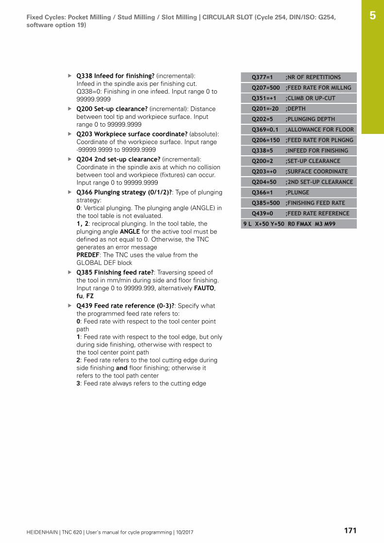
Fixed Cycles: Pocket Milling / Stud Milling / Slot Milling | CIRCULAR SLOT (Cycle 254, DIN/ISO: G254,software option 19)
5
HEIDENHAIN | TNC 620 | User’s manual for cycle programming | 10/2017 171
Q338 Infeed for finishing? (incremental):Infeed in the spindle axis per finishing cut.Q338=0: Finishing in one infeed. Input range 0 to99999.9999Q200 Set-up clearance? (incremental): Distancebetween tool tip and workpiece surface. Inputrange 0 to 99999.9999Q203 Workpiece surface coordinate? (absolute):Coordinate of the workpiece surface. Input range-99999.9999 to 99999.9999Q204 2nd set-up clearance? (incremental):Coordinate in the spindle axis at which no collisionbetween tool and workpiece (fixtures) can occur.Input range 0 to 99999.9999Q366 Plunging strategy (0/1/2)?: Type of plungingstrategy:0: Vertical plunging. The plunging angle (ANGLE) inthe tool table is not evaluated.1, 2: reciprocal plunging. In the tool table, theplunging angle ANGLE for the active tool must bedefined as not equal to 0. Otherwise, the TNCgenerates an error messagePREDEF: The TNC uses the value from theGLOBAL DEF blockQ385 Finishing feed rate?: Traversing speed ofthe tool in mm/min during side and floor finishing.Input range 0 to 99999.999, alternatively FAUTO,fu, FZQ439 Feed rate reference (0-3)?: Specify whatthe programmed feed rate refers to:0: Feed rate with respect to the tool center pointpath1: Feed rate with respect to the tool edge, but onlyduring side finishing, otherwise with respect tothe tool center point path2: Feed rate refers to the tool cutting edge duringside finishing and floor finishing; otherwise itrefers to the tool path center3: Feed rate always refers to the cutting edge
Q377=1 ;NR OF REPETITIONS
Q207=500 ;FEED RATE FOR MILLNG
Q351=+1 ;CLIMB OR UP-CUT
Q201=-20 ;DEPTH
Q202=5 ;PLUNGING DEPTH
Q369=0.1 ;ALLOWANCE FOR FLOOR
Q206=150 ;FEED RATE FOR PLNGNG
Q338=5 ;INFEED FOR FINISHING
Q200=2 ;SET-UP CLEARANCE
Q203=+0 ;SURFACE COORDINATE
Q204=50 ;2ND SET-UP CLEARANCE
Q366=1 ;PLUNGE
Q385=500 ;FINISHING FEED RATE
Q439=0 ;FEED RATE REFERENCE
9 L X+50 Y+50 R0 FMAX M3 M99
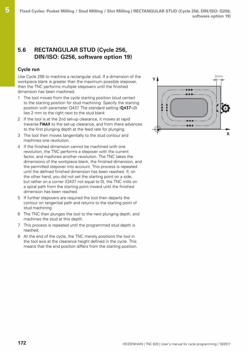
Fixed Cycles: Pocket Milling / Stud Milling / Slot Milling | RECTANGULAR STUD (Cycle 256, DIN/ISO: G256,software option 19)
5
172 HEIDENHAIN | TNC 620 | User’s manual for cycle programming | 10/2017
5.6 RECTANGULAR STUD (Cycle 256,DIN/ISO: G256, software option 19)
Cycle runUse Cycle 256 to machine a rectangular stud. If a dimension of theworkpiece blank is greater than the maximum possible stepover,then the TNC performs multiple stepovers until the finisheddimension has been machined.1 The tool moves from the cycle starting position (stud center)
to the starting position for stud machining. Specify the startingposition with parameter Q437. The standard setting (Q437=0)lies 2 mm to the right next to the stud blank
2 If the tool is at the 2nd set-up clearance, it moves at rapidtraverse FMAX to the set-up clearance, and from there advancesto the first plunging depth at the feed rate for plunging.
3 The tool then moves tangentially to the stud contour andmachines one revolution.
4 If the finished dimension cannot be machined with onerevolution, the TNC performs a stepover with the currentfactor, and machines another revolution. The TNC takes thedimensions of the workpiece blank, the finished dimension, andthe permitted stepover into account. This process is repeateduntil the defined finished dimension has been reached. If, onthe other hand, you did not set the starting point on a side,but rather on a corner (Q437 not equal to 0), the TNC mills ona spiral path from the starting point inward until the finisheddimension has been reached.
5 If further stepovers are required the tool then departs thecontour on tangential path and returns to the starting point ofstud machining
6 The TNC then plunges the tool to the next plunging depth, andmachines the stud at this depth.
7 This process is repeated until the programmed stud depth isreached.
8 At the end of the cycle, the TNC merely positions the tool inthe tool axis at the clearance height defined in the cycle. Thismeans that the end position differs from the starting position.

Fixed Cycles: Pocket Milling / Stud Milling / Slot Milling | RECTANGULAR STUD (Cycle 256, DIN/ISO: G256,software option 19)
5
HEIDENHAIN | TNC 620 | User’s manual for cycle programming | 10/2017 173
Please note while programming:
Pre-position the tool in the machining plane to thestarting position with radius compensation R0. Noteparameter Q367 (position).The TNC automatically pre-positions the tool in the toolaxis. Observe Q204 2ND SET-UP CLEARANCE.The algebraic sign for the cycle parameter DEPTHdetermines the working direction. If you programDEPTH=0, the cycle will not be executed.The TNC reduces the infeed depth to the LCUTS toollength defined in the tool table if the tool length isshorter than the Q202 infeed depth programmed in thecycle.
NOTICEDanger of collision!
If you enter a positive depth with a cycle, the TNC reversescalculation of the pre-positioning. This means that the toolmoves at rapid traverse in the tool axis to set-up clearancebelow the workpiece surface!
Enter depth as negativeEnter in machine parameter displayDepthErr (No. 201003)whether the TNC should output an error message (on) or not(off) if a positive depth is entered
NOTICEDanger of collision!
There is a danger of collision if there is insufficient room next tothe stud.
Depending on the approach position Q439, the TNC requiresroom for the approach motionLeave room next to the stud for the approach motionAt least tool diameter + 2 mmAt the end, the TNC positions the tool back to the set-up clearance, or to the 2nd set-up clearance if one wasprogrammed. This means that the end position of the toolafter the cycle differs from the starting position.
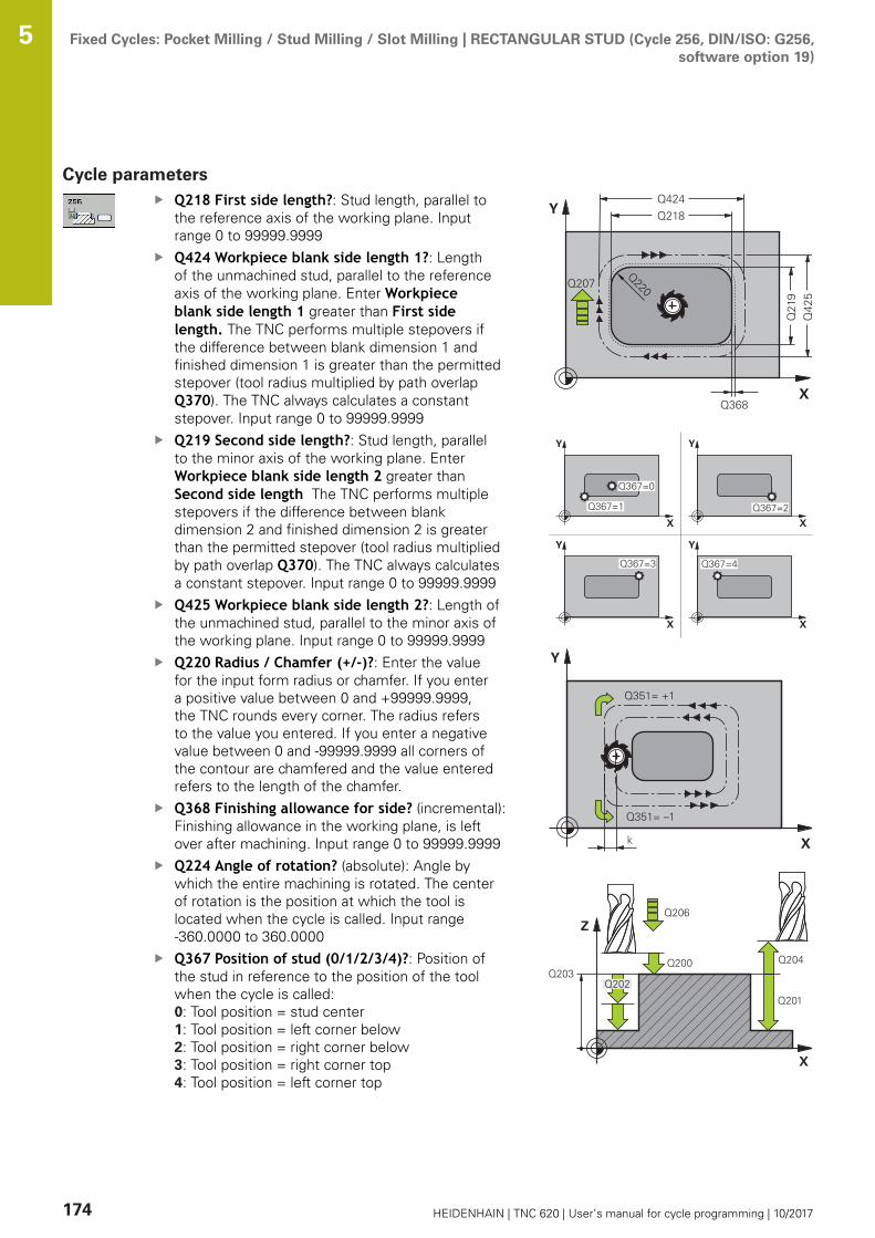
Fixed Cycles: Pocket Milling / Stud Milling / Slot Milling | RECTANGULAR STUD (Cycle 256, DIN/ISO: G256,software option 19)
5
174 HEIDENHAIN | TNC 620 | User’s manual for cycle programming | 10/2017
Cycle parametersQ218 First side length?: Stud length, parallel tothe reference axis of the working plane. Inputrange 0 to 99999.9999Q424 Workpiece blank side length 1?: Lengthof the unmachined stud, parallel to the referenceaxis of the working plane. Enter Workpieceblank side length 1 greater than First sidelength. The TNC performs multiple stepovers ifthe difference between blank dimension 1 andfinished dimension 1 is greater than the permittedstepover (tool radius multiplied by path overlapQ370). The TNC always calculates a constantstepover. Input range 0 to 99999.9999Q219 Second side length?: Stud length, parallelto the minor axis of the working plane. EnterWorkpiece blank side length 2 greater thanSecond side length The TNC performs multiplestepovers if the difference between blankdimension 2 and finished dimension 2 is greaterthan the permitted stepover (tool radius multipliedby path overlap Q370). The TNC always calculatesa constant stepover. Input range 0 to 99999.9999Q425 Workpiece blank side length 2?: Length ofthe unmachined stud, parallel to the minor axis ofthe working plane. Input range 0 to 99999.9999Q220 Radius / Chamfer (+/-)?: Enter the valuefor the input form radius or chamfer. If you entera positive value between 0 and +99999.9999,the TNC rounds every corner. The radius refersto the value you entered. If you enter a negativevalue between 0 and -99999.9999 all corners ofthe contour are chamfered and the value enteredrefers to the length of the chamfer.Q368 Finishing allowance for side? (incremental):Finishing allowance in the working plane, is leftover after machining. Input range 0 to 99999.9999Q224 Angle of rotation? (absolute): Angle bywhich the entire machining is rotated. The centerof rotation is the position at which the tool islocated when the cycle is called. Input range-360.0000 to 360.0000Q367 Position of stud (0/1/2/3/4)?: Position ofthe stud in reference to the position of the toolwhen the cycle is called:0: Tool position = stud center1: Tool position = left corner below 2: Tool position = right corner below3: Tool position = right corner top 4: Tool position = left corner top
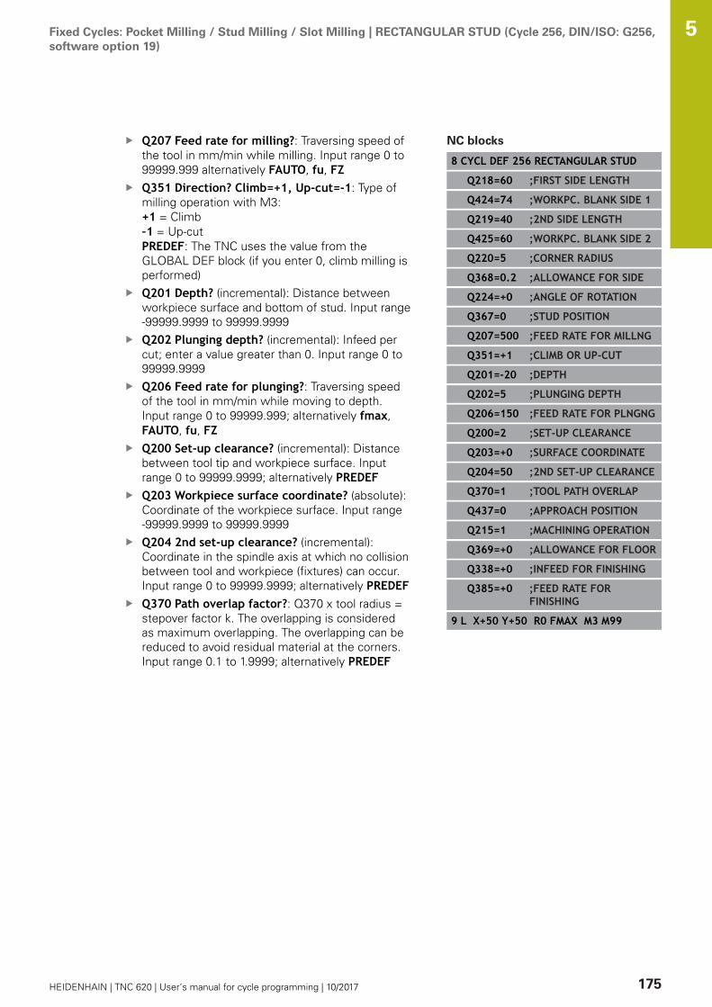
Fixed Cycles: Pocket Milling / Stud Milling / Slot Milling | RECTANGULAR STUD (Cycle 256, DIN/ISO: G256,software option 19)
5
HEIDENHAIN | TNC 620 | User’s manual for cycle programming | 10/2017 175
Q207 Feed rate for milling?: Traversing speed ofthe tool in mm/min while milling. Input range 0 to99999.999 alternatively FAUTO, fu, FZQ351 Direction? Climb=+1, Up-cut=-1: Type ofmilling operation with M3:+1 = Climb–1 = Up-cutPREDEF: The TNC uses the value from theGLOBAL DEF block (if you enter 0, climb milling isperformed)Q201 Depth? (incremental): Distance betweenworkpiece surface and bottom of stud. Input range-99999.9999 to 99999.9999Q202 Plunging depth? (incremental): Infeed percut; enter a value greater than 0. Input range 0 to99999.9999Q206 Feed rate for plunging?: Traversing speedof the tool in mm/min while moving to depth.Input range 0 to 99999.999; alternatively fmax,FAUTO, fu, FZQ200 Set-up clearance? (incremental): Distancebetween tool tip and workpiece surface. Inputrange 0 to 99999.9999; alternatively PREDEFQ203 Workpiece surface coordinate? (absolute):Coordinate of the workpiece surface. Input range-99999.9999 to 99999.9999Q204 2nd set-up clearance? (incremental):Coordinate in the spindle axis at which no collisionbetween tool and workpiece (fixtures) can occur.Input range 0 to 99999.9999; alternatively PREDEFQ370 Path overlap factor?: Q370 x tool radius =stepover factor k. The overlapping is consideredas maximum overlapping. The overlapping can bereduced to avoid residual material at the corners.Input range 0.1 to 1.9999; alternatively PREDEF
NC blocks
8 CYCL DEF 256 RECTANGULAR STUD
Q218=60 ;FIRST SIDE LENGTH
Q424=74 ;WORKPC. BLANK SIDE 1
Q219=40 ;2ND SIDE LENGTH
Q425=60 ;WORKPC. BLANK SIDE 2
Q220=5 ;CORNER RADIUS
Q368=0.2 ;ALLOWANCE FOR SIDE
Q224=+0 ;ANGLE OF ROTATION
Q367=0 ;STUD POSITION
Q207=500 ;FEED RATE FOR MILLNG
Q351=+1 ;CLIMB OR UP-CUT
Q201=-20 ;DEPTH
Q202=5 ;PLUNGING DEPTH
Q206=150 ;FEED RATE FOR PLNGNG
Q200=2 ;SET-UP CLEARANCE
Q203=+0 ;SURFACE COORDINATE
Q204=50 ;2ND SET-UP CLEARANCE
Q370=1 ;TOOL PATH OVERLAP
Q437=0 ;APPROACH POSITION
Q215=1 ;MACHINING OPERATION
Q369=+0 ;ALLOWANCE FOR FLOOR
Q338=+0 ;INFEED FOR FINISHING
Q385=+0 ;FEED RATE FORFINISHING
9 L X+50 Y+50 R0 FMAX M3 M99
Fixed Cycles: Pocket Milling / Stud Milling / Slot Milling | RECTANGULAR STUD (Cycle 256, DIN/ISO: G256,software option 19)
5
176 HEIDENHAIN | TNC 620 | User’s manual for cycle programming | 10/2017
Q437 Starting position (0...4)?: Define theapproach strategy of the tool: 0: Right of the stud (default setting)1: left corner below2: right corner below3: right corner top4: left corner top. If approach marks should be appear on the studsurface during approach with the setting Q437=0,then choose another approach position.Q215 Machining operation (0/1/2)?: Definemachining operation:0: Roughing and finishing1: Only roughing2: Only finishing Side finishing and floor finishing are only machinedwhen the specific allowance (Q368, Q369) isdefinedQ369 Finishing allowance for floor?(incremental): Finishing allowance for the floor.Input range 0 to 99999.9999Q338 Infeed for finishing? (incremental):Infeed in the spindle axis per finishing cut.Q338=0: Finishing in one infeed. Input range 0 to99999.9999Q385 Finishing feed rate?: Traversing speed ofthe tool in mm/min during side and floor finishing.Input range 0 to 99999.999, alternatively FAUTO,fu, FZ

Fixed Cycles: Pocket Milling / Stud Milling / Slot Milling | CIRCULAR STUD (Cycle 257, DIN/ISO: G257,software option 19)
5
HEIDENHAIN | TNC 620 | User’s manual for cycle programming | 10/2017 177
5.7 CIRCULAR STUD (Cycle 257, DIN/ISO:G257, software option 19)
Cycle runUse Cycle 257 to machine a circular stud. The TNC mills the circularstud with a helical infeed motion starting from the workpiece blankdiameter.1 If the tool is below the 2nd set-up clearance, the TNC retracts
the tool to the 2nd set-up clearance. 2 The tool moves from the stud center to the starting position for
stud machining. With the polar angle you specify the startingposition with respect to the stud center using parameter Q376.
3 The TNC moves the tool at rapid traverse FMAX to the set-upclearance Q200, and from there advances to the first plungingdepth at the feed rate for plunging.
4 The TNC then machines the circular stud with a helical infeedmotion, taking the path overlap into account.
5 The TNC retracts the tool from the contour by 2 mm on atangential path.
6 If more than one plunging movement is required, the toolrepeats the plunging movement at the point next to thedeparture movement.
7 This process is repeated until the programmed stud depth isreached.
8 At the end of the cycle, the tool departs on a tangential path andthen retracts in the tool axis to the 2nd set-up clearance definedin the cycle.

Fixed Cycles: Pocket Milling / Stud Milling / Slot Milling | CIRCULAR STUD (Cycle 257, DIN/ISO: G257,software option 19)
5
178 HEIDENHAIN | TNC 620 | User’s manual for cycle programming | 10/2017
Please note while programming:
Pre-position the tool in the machining plane to thestarting position (stud center) with radius compensationR0.The TNC automatically pre-positions the tool in the toolaxis. Observe Q204 2ND SET-UP CLEARANCE.The algebraic sign for the cycle parameter DEPTHdetermines the working direction. If you programDEPTH=0, the cycle will not be executed.At the end of the cycle, the TNC returns the tool to thestarting position.The TNC reduces the infeed depth to the LCUTS toollength defined in the tool table if the tool length isshorter than the Q202 infeed depth programmed in thecycle.
NOTICEDanger of collision!
If you enter a positive depth with a cycle, the TNC reversescalculation of the pre-positioning. This means that the toolmoves at rapid traverse in the tool axis to set-up clearancebelow the workpiece surface!
Enter depth as negativeEnter in machine parameter displayDepthErr (No. 201003)whether the TNC should output an error message (on) or not(off) if a positive depth is entered
NOTICEDanger of collision!
There is a danger of collision if there is insufficient room next tothe stud.
The TNC performs an approach motion with this cycleTo define the precise starting position, enter a starting angleof 0° to 360° in parameter Q376Depending on the starting angle Q376, the following amountof space must be left next to the stud: At least tool diameter+2 mmIf you use the default value -1 the TNC automaticallycalculates the starting position

Fixed Cycles: Pocket Milling / Stud Milling / Slot Milling | CIRCULAR STUD (Cycle 257, DIN/ISO: G257,software option 19)
5
HEIDENHAIN | TNC 620 | User’s manual for cycle programming | 10/2017 179
Cycle parametersQ223 Finished part diameter?: Diameter of thefinished stud. Input range 0 to 99999.9999Q222 Workpiece blank diameter?: Diameterof workpiece blank. Enter the workpiece blankdiameter greater than the finished diameter. TheTNC performs multiple stepovers if the differencebetween the workpiece blank diameter andfinished diameter is greater than the permittedstepover (tool radius multiplied by path overlapQ370). The TNC always calculates a constantstepover. Input range 0 to 99999.9999Q368 Finishing allowance for side? (incremental):Finishing allowance in the machining plane. Inputrange 0 to 99999.9999Q207 Feed rate for milling?: Traversing speed ofthe tool in mm/min while milling. Input range 0 to99999.999 alternatively FAUTO, fu, FZQ351 Direction? Climb=+1, Up-cut=-1: Type ofmilling operation with M3:+1 = Climb–1 = Up-cutPREDEF: The TNC uses the value from theGLOBAL DEF block (if you enter 0, climb milling isperformed)Q201 Depth? (incremental): Distance betweenworkpiece surface and bottom of stud. Input range-99999.9999 to 99999.9999Q202 Plunging depth? (incremental): Infeed percut; enter a value greater than 0. Input range 0 to99999.9999Q206 Feed rate for plunging?: Traversing speedof the tool in mm/min while moving to depth.Input range 0 to 99999.999; alternatively fmax,FAUTO, fu, FZQ200 Set-up clearance? (incremental): Distancebetween tool tip and workpiece surface. Inputrange 0 to 99999.9999; alternatively PREDEF

Fixed Cycles: Pocket Milling / Stud Milling / Slot Milling | CIRCULAR STUD (Cycle 257, DIN/ISO: G257,software option 19)
5
180 HEIDENHAIN | TNC 620 | User’s manual for cycle programming | 10/2017
Q203 Workpiece surface coordinate? (absolute):Coordinate of the workpiece surface. Input range-99999.9999 to 99999.9999Q204 2nd set-up clearance? (incremental):Coordinate in the spindle axis at which no collisionbetween tool and workpiece (fixtures) can occur.Input range 0 to 99999.9999; alternatively PREDEFQ370 Path overlap factor?: Q370 x tool radius =stepover factor k. Input range: 0.0001 to 1.9999alternatively PREDEFQ376 Starting angle?: Polar angle relative to thestud center from which the tool approaches thestud. Input range 0 to 359°Q215 Machining operation (0/1/2)?: Define theextent of machining:0: Roughing and finishing1: Roughing only2: Finishing onlyQ369 Finishing allowance for floor?(incremental): Finishing allowance for the floor.Input range 0 to 99999.9999Q338 Infeed for finishing? (incremental):Infeed in the spindle axis per finishing cut.Q338=0: Finishing in one infeed. Input range 0 to99999.9999Q385 Finishing feed rate?: Traversing speed ofthe tool in mm/min during side and floor finishing.Input range 0 to 99999.999, alternatively FAUTO,fu, FZ
NC blocks
8 CYCL DEF 257 CIRCULAR STUD
Q223=60 ;FINISHED PART DIA.
Q222=60 ;WORKPIECE BLANK DIA.
Q368=0.2 ;ALLOWANCE FOR SIDE
Q207=500 ;FEED RATE FOR MILLNG
Q351=+1 ;CLIMB OR UP-CUT
Q201=-20 ;DEPTH
Q202=5 ;PLUNGING DEPTH
Q206=150 ;FEED RATE FOR PLNGNG
Q200=2 ;SET-UP CLEARANCE
Q203=+0 ;SURFACE COORDINATE
Q204=50 ;2ND SET-UP CLEARANCE
Q370=1 ;TOOL PATH OVERLAP
Q376=0 ;STARTING ANGLE
Q215=+1 ;MACHINING OPERATION
Q369=0 ;ALLOWANCE FOR FLOOR
Q338=0 ;INFEED FOR FINISHING
Q385=+500 ;FINISHING FEED RATE
9 L X+50 Y+50 R0 FMAX M3 M99
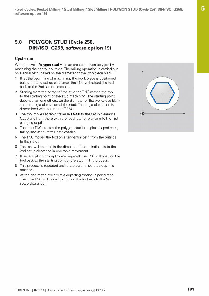
Fixed Cycles: Pocket Milling / Stud Milling / Slot Milling | POLYGON STUD (Cycle 258, DIN/ISO: G258,software option 19)
5
HEIDENHAIN | TNC 620 | User’s manual for cycle programming | 10/2017 181
5.8 POLYGON STUD (Cycle 258,DIN/ISO: G258, software option 19)
Cycle runWith the cycle Polygon stud you can create an even polygon bymachining the contour outside. The milling operation is carried outon a spiral path, based on the diameter of the workpiece blank.1 If, at the beginning of machining, the work piece is positioned
below the 2nd set-up clearance, the TNC will retract the toolback to the 2nd setup clearance.
2 Starting from the center of the stud the TNC moves the toolto the starting point of the stud machining. The starting pointdepends, among others, on the diameter of the workpiece blankand the angle of rotation of the stud. The angle of rotation isdetermined with parameter Q224.
3 The tool moves at rapid traverse FMAX to the setup clearanceQ200 and from there with the feed rate for plunging to the firstplunging depth.
4 Then the TNC creates the polygon stud in a spiral-shaped pass,taking into account the path overlap
5 The TNC moves the tool on a tangential path from the outsideto the inside
6 The tool will be lifted in the direction of the spindle axis to the2nd setup clearance in one rapid movement
7 If several plunging depths are required, the TNC will position thetool back to the starting point of the stud milling process.
8 This process is repeated until the programmed stud depth isreached.
9 At the end of the cycle first a departing motion is performed.Then the TNC will move the tool on the tool axis to the 2ndsetup clearance.

Fixed Cycles: Pocket Milling / Stud Milling / Slot Milling | POLYGON STUD (Cycle 258, DIN/ISO: G258,software option 19)
5
182 HEIDENHAIN | TNC 620 | User’s manual for cycle programming | 10/2017
Please note while programming:
Before the start of the cycle you will have to prepositionthe tool on the machining plane. In order to do so, movethe tool with radius compensation R0 to the center ofthe stud.The TNC automatically pre-positions the tool in the toolaxis. Observe Q204 2ND SET-UP CLEARANCE.The algebraic sign for the cycle parameter DEPTHdetermines the working direction. If you programDEPTH=0, the cycle will not be executed.The TNC reduces the infeed depth to the LCUTS toollength defined in the tool table if the tool length isshorter than the Q202 infeed depth programmed in thecycle.
NOTICEDanger of collision!
If you enter a positive depth with a cycle, the TNC reversescalculation of the pre-positioning. This means that the toolmoves at rapid traverse in the tool axis to set-up clearancebelow the workpiece surface!
Enter depth as negativeEnter in machine parameter displayDepthErr (No. 201003)whether the TNC should output an error message (on) or not(off) if a positive depth is entered
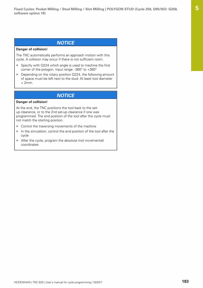
Fixed Cycles: Pocket Milling / Stud Milling / Slot Milling | POLYGON STUD (Cycle 258, DIN/ISO: G258,software option 19)
5
HEIDENHAIN | TNC 620 | User’s manual for cycle programming | 10/2017 183
NOTICEDanger of collision!
The TNC automatically performs an approach motion with thiscycle. A collision may occur if there is not sufficient room.
Specify with Q224 which angle is used to machine the firstcorner of the polygon. Input range: -360° to +360°Depending on the rotary position Q224, the following amountof space must be left next to the stud: At least tool diameter+ 2mm.
NOTICEDanger of collision!
At the end, the TNC positions the tool back to the set-up clearance, or to the 2nd set-up clearance if one wasprogrammed. The end position of the tool after the cycle mustnot match the starting position.
Control the traversing movements of the machineIn the simulation, control the end position of the tool after thecycleAfter the cycle, program the absolute (not incremental)coordinates
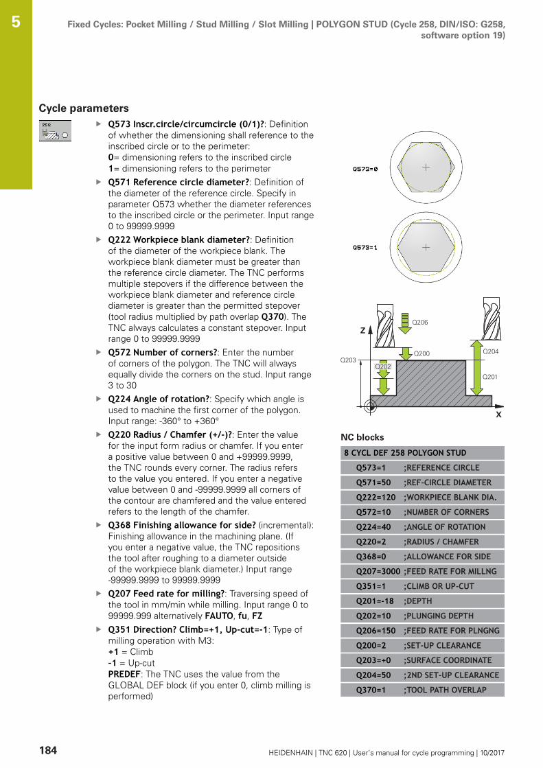
Fixed Cycles: Pocket Milling / Stud Milling / Slot Milling | POLYGON STUD (Cycle 258, DIN/ISO: G258,software option 19)
5
184 HEIDENHAIN | TNC 620 | User’s manual for cycle programming | 10/2017
Cycle parametersQ573 Inscr.circle/circumcircle (0/1)?: Definitionof whether the dimensioning shall reference to theinscribed circle or to the perimeter:0= dimensioning refers to the inscribed circle1= dimensioning refers to the perimeterQ571 Reference circle diameter?: Definition ofthe diameter of the reference circle. Specify inparameter Q573 whether the diameter referencesto the inscribed circle or the perimeter. Input range0 to 99999.9999Q222 Workpiece blank diameter?: Definitionof the diameter of the workpiece blank. Theworkpiece blank diameter must be greater thanthe reference circle diameter. The TNC performsmultiple stepovers if the difference between theworkpiece blank diameter and reference circlediameter is greater than the permitted stepover(tool radius multiplied by path overlap Q370). TheTNC always calculates a constant stepover. Inputrange 0 to 99999.9999Q572 Number of corners?: Enter the numberof corners of the polygon. The TNC will alwaysequally divide the corners on the stud. Input range3 to 30Q224 Angle of rotation?: Specify which angle isused to machine the first corner of the polygon.Input range: -360° to +360°Q220 Radius / Chamfer (+/-)?: Enter the valuefor the input form radius or chamfer. If you entera positive value between 0 and +99999.9999,the TNC rounds every corner. The radius refersto the value you entered. If you enter a negativevalue between 0 and -99999.9999 all corners ofthe contour are chamfered and the value enteredrefers to the length of the chamfer.Q368 Finishing allowance for side? (incremental):Finishing allowance in the machining plane. (Ifyou enter a negative value, the TNC repositionsthe tool after roughing to a diameter outsideof the workpiece blank diameter.) Input range-99999.9999 to 99999.9999Q207 Feed rate for milling?: Traversing speed ofthe tool in mm/min while milling. Input range 0 to99999.999 alternatively FAUTO, fu, FZQ351 Direction? Climb=+1, Up-cut=-1: Type ofmilling operation with M3:+1 = Climb–1 = Up-cutPREDEF: The TNC uses the value from theGLOBAL DEF block (if you enter 0, climb milling isperformed)
NC blocks
8 CYCL DEF 258 POLYGON STUD
Q573=1 ;REFERENCE CIRCLE
Q571=50 ;REF-CIRCLE DIAMETER
Q222=120 ;WORKPIECE BLANK DIA.
Q572=10 ;NUMBER OF CORNERS
Q224=40 ;ANGLE OF ROTATION
Q220=2 ;RADIUS / CHAMFER
Q368=0 ;ALLOWANCE FOR SIDE
Q207=3000 ;FEED RATE FOR MILLNG
Q351=1 ;CLIMB OR UP-CUT
Q201=-18 ;DEPTH
Q202=10 ;PLUNGING DEPTH
Q206=150 ;FEED RATE FOR PLNGNG
Q200=2 ;SET-UP CLEARANCE
Q203=+0 ;SURFACE COORDINATE
Q204=50 ;2ND SET-UP CLEARANCE
Q370=1 ;TOOL PATH OVERLAP
Fixed Cycles: Pocket Milling / Stud Milling / Slot Milling | POLYGON STUD (Cycle 258, DIN/ISO: G258,software option 19)
5
HEIDENHAIN | TNC 620 | User’s manual for cycle programming | 10/2017 185
Q201 Depth? (incremental): Distance betweenworkpiece surface and bottom of stud. Input range-99999.9999 to 99999.9999Q202 Plunging depth? (incremental): Infeed percut; enter a value greater than 0. Input range 0 to99999.9999Q206 Feed rate for plunging?: Traversing speedof the tool in mm/min while moving to depth.Input range 0 to 99999.999; alternatively fmax,FAUTO, fu, FZQ200 Set-up clearance? (incremental): Distancebetween tool tip and workpiece surface. Inputrange 0 to 99999.9999; alternatively PREDEFQ203 Workpiece surface coordinate? (absolute):Coordinate of the workpiece surface. Input range-99999.9999 to 99999.9999Q204 2nd set-up clearance? (incremental):Coordinate in the spindle axis at which no collisionbetween tool and workpiece (fixtures) can occur.Input range 0 to 99999.9999; alternatively PREDEFQ370 Path overlap factor?: Q370 x tool radius =stepover factor k. Input range: 0.0001 to 1.9999alternatively PREDEFQ215 Machining operation (0/1/2)?: Definemachining operation:0: Roughing and finishing1: Only roughing2: Only finishing Side finishing and floor finishing are only machinedwhen the specific allowance (Q368, Q369) isdefinedQ369 Finishing allowance for floor?(incremental): Finishing allowance for the floor.Input range 0 to 99999.9999Q338 Infeed for finishing? (incremental):Infeed in the spindle axis per finishing cut.Q338=0: Finishing in one infeed. Input range 0 to99999.9999Q385 Finishing feed rate?: Traversing speed ofthe tool in mm/min during side and floor finishing.Input range 0 to 99999.999, alternatively FAUTO,fu, FZ
Q215=0 ;MACHINING OPERATION
Q369=0 ;ALLOWANCE FOR FLOOR
Q338=0 ;INFEED FOR FINISHING
Q385=500 ;FINISHING FEED RATE
9 L X+50 Y+50 R0 FMAX M3 M99

Fixed Cycles: Pocket Milling / Stud Milling / Slot Milling | FACE MILLING (Cycle 233, DIN/ISO: G233,software option 19)
5
186 HEIDENHAIN | TNC 620 | User’s manual for cycle programming | 10/2017
5.9 FACE MILLING (Cycle 233, DIN/ISO:G233, software option 19)
Cycle runCycle 233 is used to face mill a level surface in multiple infeedswhile taking the finishing allowance into account. Additionally,you can also define side walls in the cycle which are taken intoaccount during the machining of the level surface The cycle offersyou various machining strategies:
Strategy Q389=0: Meander machining, stepover outside thesurface being machinedStrategy Q389=1: Meander machining, stepover at the edge ofthe surface being machinedStrategy Q389=2: The surface is machined line by line withovertravel; stepover when retracting at rapid traverseStrategy Q389=3: The surface is machined line by line withoutovertravel; stepover when retracting at rapid traverseStrategy Q389=4: Helical machining from the outside towardthe inside
1 From the current position, the TNC positions the tool at rapidtraverse FMAX to the starting point 1 in the working plane: Thestarting point in the working plane is offset from the edge ofthe workpiece by the tool radius and the safety clearance to theside.
2 The TNC then positions the tool at rapid traverse FMAX to theset-up clearance in the spindle axis.
3 The tool then moves in the tool axis at the feed rate for millingQ207 to the first plunging depth calculated by the TNC.
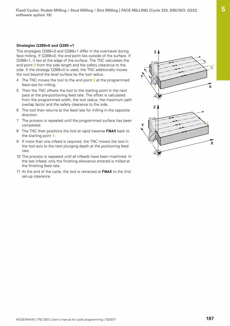
Fixed Cycles: Pocket Milling / Stud Milling / Slot Milling | FACE MILLING (Cycle 233, DIN/ISO: G233,software option 19)
5
HEIDENHAIN | TNC 620 | User’s manual for cycle programming | 10/2017 187
Strategies Q389=0 and Q389 =1
The strategies Q389=0 and Q389=1 differ in the overtravel duringface milling. If Q389=0, the end point lies outside of the surface. IfQ389=1, it lies at the edge of the surface. The TNC calculates theend point 2 from the side length and the safety clearance to theside. If the strategy Q389=0 is used, the TNC additionally movesthe tool beyond the level surface by the tool radius.4 The TNC moves the tool to the end point 2 at the programmed
feed rate for milling.5 Then the TNC offsets the tool to the starting point in the next
pass at the pre-positioning feed rate. The offset is calculatedfrom the programmed width, the tool radius, the maximum pathoverlap factor and the safety clearance to the side.
6 The tool then returns at the feed rate for milling in the oppositedirection.
7 The process is repeated until the programmed surface has beencompleted.
8 The TNC then positions the tool at rapid traverse FMAX back tothe starting point 1.
9 If more than one infeed is required, the TNC moves the tool inthe tool axis to the next plunging depth at the positioning feedrate.
10 The process is repeated until all infeeds have been machined. Inthe last infeed, only the finishing allowance entered is milled atthe finishing feed rate.
11 At the end of the cycle, the tool is retracted at FMAX to the 2ndset-up clearance.

Fixed Cycles: Pocket Milling / Stud Milling / Slot Milling | FACE MILLING (Cycle 233, DIN/ISO: G233,software option 19)
5
188 HEIDENHAIN | TNC 620 | User’s manual for cycle programming | 10/2017
Strategies Q389=2 and Q389 =3
The strategies Q389=2 and Q389=3 differ in the overtravel duringface milling. If Q389=2, the end point lies outside of the surface. IfQ389=3, it lies at the edge of the surface. The TNC calculates theend point 2 from the side length and the safety clearance to theside. If the strategy Q389=2 is used, the TNC additionally movesthe tool beyond the level surface by the tool radius.4 The tool subsequently advances to the end point 2 at the
programmed feed rate for milling.5 The TNC positions the tool in the spindle axis to the set-up
clearance over the current infeed depth, and then moves atFMAXdirectly back to the starting point in the next line. TheTNC calculates the offset from the programmed width, thetool radius, the maximum path overlap factor and the safetyclearance to the side.
6 The tool then returns to the current infeed depth and moves inthe direction of the next end point 2.
7 The multipass process is repeated until the programmedsurface has been completed. At the end of the last path, theTNC positions the tool at rapid traverse FMAX back to thestarting point 1.
8 If more than one infeed is required, the TNC moves the tool inthe tool axis to the next plunging depth at the positioning feedrate.
9 The process is repeated until all infeeds have been machined. Inthe last infeed, only the finishing allowance entered is milled atthe finishing feed rate.
10 At the end of the cycle, the tool is retracted at FMAX to the 2ndset-up clearance.
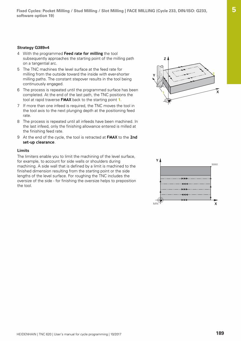
Fixed Cycles: Pocket Milling / Stud Milling / Slot Milling | FACE MILLING (Cycle 233, DIN/ISO: G233,software option 19)
5
HEIDENHAIN | TNC 620 | User’s manual for cycle programming | 10/2017 189
Strategy Q389=4
4 With the programmed Feed rate for milling the toolsubsequently approaches the starting point of the milling pathon a tangential arc.
5 The TNC machines the level surface at the feed rate formilling from the outside toward the inside with ever-shortermilling paths. The constant stepover results in the tool beingcontinuously engaged.
6 The process is repeated until the programmed surface has beencompleted. At the end of the last path, the TNC positions thetool at rapid traverse FMAX back to the starting point 1.
7 If more than one infeed is required, the TNC moves the tool inthe tool axis to the next plunging depth at the positioning feedrate.
8 The process is repeated until all infeeds have been machined. Inthe last infeed, only the finishing allowance entered is milled atthe finishing feed rate.
9 At the end of the cycle, the tool is retracted at FMAX to the 2ndset-up clearance.
Limits
The limiters enable you to limit the machining of the level surface,for example, to account for side walls or shoulders duringmachining. A side wall that is defined by a limit is machined to thefinished dimension resulting from the starting point or the sidelengths of the level surface. For roughing the TNC includes theoversize of the side - for finishing the oversize helps to prepositionthe tool.
Fixed Cycles: Pocket Milling / Stud Milling / Slot Milling | FACE MILLING (Cycle 233, DIN/ISO: G233,software option 19)
5
190 HEIDENHAIN | TNC 620 | User’s manual for cycle programming | 10/2017
Please note while programming:
Pre-position the tool in the machining plane to thestarting position with radius compensation R0. Keep inmind the machining direction.The TNC automatically pre-positions the tool in the toolaxis. Observe Q204 2ND SET-UP CLEARANCE.Enter the Q204 2ND SET-UP CLEARANCE so that nocollision with the workpiece or the fixtures can occur.If Q227 STARTNG PNT 3RD AXIS and Q386 END POINT3RD AXIS are entered as equal values, the TNC will notcarry out the cycle (depth=0 programmed).The TNC reduces the infeed depth to the LCUTS toollength defined in the tool table if the tool length isshorter than the Q202 infeed depth programmed in thecycle.If you define Q370 TOOL PATH OVERLAP >1, theprogrammed overlap factor is taken into account fromthe first machining path.Cycle 233 monitors the entry for tool length / length ofthe cutting edge LCUTS in the tool table. If the length ofthe tool or teeth is not sufficient for finishing operations,The TNC subdivides the machining into several workingsteps.
NOTICEDanger of collision!
If you enter a positive depth with a cycle, the TNC reversescalculation of the pre-positioning. This means that the toolmoves at rapid traverse in the tool axis to set-up clearancebelow the workpiece surface!
Enter depth as negativeEnter in machine parameter displayDepthErr (No. 201003)whether the TNC should output an error message (on) or not(off) if a positive depth is entered

Fixed Cycles: Pocket Milling / Stud Milling / Slot Milling | FACE MILLING (Cycle 233, DIN/ISO: G233,software option 19)
5
HEIDENHAIN | TNC 620 | User’s manual for cycle programming | 10/2017 191
Cycle parametersQ215 Machining operation (0/1/2)?: Definemachining operation:0: Roughing and finishing1: Only roughing2: Only finishing Side finishing and floor finishing are only machinedwhen the specific allowance (Q368, Q369) isdefinedQ389 Machining strategy (0-4)?: Determine howthe TNC should machine the surface:0: Meander machining, stepover at the positioningfeed rate outside the surface being machined1: Meander machining, stepover at the feedrate for milling at the edge of the surface beingmachined2: Line-by-line machining, retraction and stepoverat the positioning feed rate3: Line-by-line machining, retraction and stepoverat the edge of the surface being machined4: Helical machining, smooth approach from theoutside toward the insideQ350 Milling direction?: Axis in the machiningplane that defines the machining direction:1: Reference axis = machining direction2: Minor axis = machining directionQ218 First side length? (incremental): Length ofthe surface to be machined in the reference axisof the working plane, referenced to the startingpoint in the 1st axis. Input range -99999.9999 to99999.9999Q219 Second side length? (incremental): Lengthof the surface to be machined in the minor axisof the working plane. Use the algebraic signto specify the direction of the first transverseapproach in reference to the STARTNG PNT 2NDAXIS. Input range -99999.9999 to 99999.9999Q227 Starting point in 3rd axis? (absolute):Coordinate of the workpiece surface used to
Q21
9
Q357
Q227
Q347Q348 Q349
= 0
= -1 = +1
= -2 = +2

Fixed Cycles: Pocket Milling / Stud Milling / Slot Milling | FACE MILLING (Cycle 233, DIN/ISO: G233,software option 19)
5
192 HEIDENHAIN | TNC 620 | User’s manual for cycle programming | 10/2017
calculate the infeeds. Input range -99999.9999 to99999.9999Q386 End point in 3rd axis? (absolute):Coordinate in the spindle axis on which the surfaceis to be face-milled. Input range -99999.9999 to99999.9999Q369 Finishing allowance for floor?(incremental): Distance used for the last infeed.Input range 0 to 99999.9999Q202 Plunging depth? (incremental): Infeed percut; enter a value greater than 0. Input range 0 to99999.9999Q370 Path overlap factor?: Maximum stepoverfactor k. The TNC calculates the actual stepoverfrom the second side length (Q219) and the toolradius so that a constant stepover is used formachining. Input range: 0.1 to 1.9999.Q207 Feed rate for milling?: Traversing speed ofthe tool in mm/min while milling. Input range 0 to99999.999 alternatively FAUTO, fu, FZQ385 Finishing feed rate?: Traversing speed ofthe tool in mm/min while milling the last infeed.Input range 0 to 99999.9999, alternatively FAUTO,fu, FZQ253 Feed rate for pre-positioning?: Traversingspeed of the tool in mm/min when approachingthe starting position and when moving to the nextpass. If you are moving the tool transversely tothe material (Q389=1), the TNC moves the toolat the feed rate for milling Q207. Input range 0 to99999.9999, alternatively fmax, FAUTOQ357 Safety clearance to the side? (incremental)Parameter Q357 has an influence on the followingsituations: Approach the first plunging depth: Q357 isthe safety clearance of the tool to the side of theworkpieceRoughing with milling strategies Q389=0-3: Thesurface in Q350 MILLING DIRECTION is increasedby the value from Q357, provided that no limitationis set in this directionSide finishing: The paths are extended by Q357in Q350 MILLING DIRECTIONInput range 0 to 99999.9999
NC blocks
8 CYCL DEF 233 FACE MILLING
Q215=0 ;MACHINING OPERATION
Q389=2 ;MILLING STRATEGY
Q350=1 ;MILLING DIRECTION
Q218=120 ;FIRST SIDE LENGTH
Q219=80 ;2ND SIDE LENGTH
Q227=0 ;STARTNG PNT 3RD AXIS
Q386=-6 ;END POINT 3RD AXIS
Q369=0.2 ;ALLOWANCE FOR FLOOR
Q202=3 ;MAX. PLUNGING DEPTH
Q370=1 ;TOOL PATH OVERLAP
Q207=500 ;FEED RATE FOR MILLNG
Q385=500 ;FINISHING FEED RATE
Q253=750 ;F PRE-POSITIONING
Q357=2 ;CLEARANCE TO SIDE
Q200=2 ;SET-UP CLEARANCE
Q204=50 ;2ND SET-UP CLEARANCE
Q347=0 ;1ST LIMIT
Q348=0 ;2ND LIMIT
Q349=0 ;3RD LIMIT
Q220=2 ;CORNER RADIUS
Q368=0 ;ALLOWANCE FOR SIDE
Q338=0 ;INFEED FOR FINISHING
9 L X+0 Y+0 R0 FMAX M3 M99
Fixed Cycles: Pocket Milling / Stud Milling / Slot Milling | FACE MILLING (Cycle 233, DIN/ISO: G233,software option 19)
5
HEIDENHAIN | TNC 620 | User’s manual for cycle programming | 10/2017 193
Q200 Set-up clearance? (incremental): Distancebetween tool tip and workpiece surface. Inputrange 0 to 99999.9999; alternatively PREDEFQ204 2nd set-up clearance? (incremental):Coordinate in the spindle axis at which no collisionbetween tool and workpiece (fixtures) can occur.Input range 0 to 99999.9999; alternatively PREDEFQ347 1st limit?: Select the side of the workpiecewhere the plan surface is bordered by a side wall(not possible with helical machining). Dependingon the position of the side wall, the TNC limits themachining of the level surface to the respectivecoordinate of the starting point or to the sidelength: (not possible with helical machining):Input 0: No limitingInput -1: Limiting in negative principal axisInput +1: Limiting in positive principal axisInput -2: Limiting in negative secondary axisInput +2: Limiting in positive secondary axisQ348 2nd limit?: See Parameter 1st limit Q347Q349 3rd limit?: See Parameter 1st limit Q347Q220 Corner radius?: Radius of a corner at limits(Q347 to Q349). Input range 0 to 99999.9999Q368 Finishing allowance for side? (incremental):Finishing allowance in the machining plane. Inputrange 0 to 99999.9999Q338 Infeed for finishing? (incremental):Infeed in the spindle axis per finishing cut.Q338=0: Finishing in one infeed. Input range 0 to99999.9999
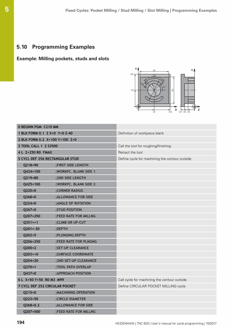
Fixed Cycles: Pocket Milling / Stud Milling / Slot Milling | Programming Examples 5
194 HEIDENHAIN | TNC 620 | User’s manual for cycle programming | 10/2017
5.10 Programming Examples
Example: Milling pockets, studs and slots
0 BEGINN PGM C210 MM
1 BLK FORM 0.1 Z X+0 Y+0 Z-40 Definition of workpiece blank
2 BLK FORM 0.2 X+100 Y+100 Z+0
3 TOOL CALL 1 Z S3500 Call the tool for roughing/finishing
4 L Z+250 R0 FMAX Retract the tool
5 CYCL DEF 256 RECTANGULAR STUD Define cycle for machining the contour outside
Q218=90 ;FIRST SIDE LENGTH
Q424=100 ;WORKPC. BLANK SIDE 1
Q219=80 ;2ND SIDE LENGTH
Q425=100 ;WORKPC. BLANK SIDE 2
Q220=0 ;CORNER RADIUS
Q368=0 ;ALLOWANCE FOR SIDE
Q224=0 ;ANGLE OF ROTATION
Q367=0 ;STUD POSITION
Q207=250 ;FEED RATE FOR MILLNG
Q351=+1 ;CLIMB OR UP-CUT
Q201=-30 ;DEPTH
Q202=5 ;PLUNGING DEPTH
Q206=250 ;FEED RATE FOR PLNGNG
Q200=2 ;SET-UP CLEARANCE
Q203=+0 ;SURFACE COORDINATE
Q204=20 ;2ND SET-UP CLEARANCE
Q370=1 ;TOOL PATH OVERLAP
Q437=0 ;APPROACH POSITION
6 L X+50 Y+50 R0 M3 M99 Call cycle for machining the contour outside
7 CYCL DEF 252 CIRCULAR POCKET Define CIRCULAR POCKET MILLING cycle
Q215=0 ;MACHINING OPERATION
Q223=50 ;CIRCLE DIAMETER
Q368=0.2 ;ALLOWANCE FOR SIDE
Q207=500 ;FEED RATE FOR MILLNG

Fixed Cycles: Pocket Milling / Stud Milling / Slot Milling | Programming Examples 5
HEIDENHAIN | TNC 620 | User’s manual for cycle programming | 10/2017 195
Q351=+1 ;CLIMB OR UP-CUT
Q201=-30 ;DEPTH
Q202=5 ;PLUNGING DEPTH
Q369=0.1 ;ALLOWANCE FOR FLOOR
Q206=150 ;FEED RATE FOR PLNGNG
Q338=5 ;INFEED FOR FINISHING
Q200=2 ;SET-UP CLEARANCE
Q203=+0 ;SURFACE COORDINATE
Q204=50 ;2ND SET-UP CLEARANCE
Q370=1 ;TOOL PATH OVERLAP
Q366=1 ;PLUNGE
Q385=750 ;FINISHING FEED RATE
Q439=0 ;FEED RATE REFERENCE
8 L X+50 Y+50 R0 FMAX M99 Call CIRCULAR POCKET MILLING cycle
9 L Z+250 R0 FMAX M6 Tool change
10 TOOL CALL 2 Z S5000 Call tool: slotting mill
11 CYCL DEF 254 CIRCULAR SLOT Define SLOT cycle
Q215=0 ;MACHINING OPERATION
Q219=8 ;SLOT WIDTH
Q368=0.2 ;ALLOWANCE FOR SIDE
Q375=70 ;PITCH CIRCLE DIAMETR
Q367=0 ;REF. SLOT POSITION No pre-positioning in X/Y required
Q216=+50 ;CENTER IN 1ST AXIS
Q217=+50 ;CENTER IN 2ND AXIS
Q376=+45 ;STARTING ANGLE
Q248=90 ;ANGULAR LENGTH
Q378=180 ;STEPPING ANGLE Starting point for second slot
Q377=2 ;NR OF REPETITIONS
Q207=500 ;FEED RATE FOR MILLNG
Q351=+1 ;CLIMB OR UP-CUT
Q201=-20 ;DEPTH
Q202=5 ;PLUNGING DEPTH
Q369=0.1 ;ALLOWANCE FOR FLOOR
Q206=150 ;FEED RATE FOR PLNGNG
Q338=5 ;INFEED FOR FINISHING
Q200=2 ;SET-UP CLEARANCE
Q203=+0 ;SURFACE COORDINATE
Q204=50 ;2ND SET-UP CLEARANCE
Q366=1 ;PLUNGE
Q385=500 ;FINISHING FEED RATE
Q439=0 ;FEED RATE REFERENCE
12 CYCL CALL FMAX M3 Call SLOT cycle
13 L Z+250 R0 FMAX M2 Retract in the tool axis, end program
Fixed Cycles: Pocket Milling / Stud Milling / Slot Milling | Programming Examples 5
196 HEIDENHAIN | TNC 620 | User’s manual for cycle programming | 10/2017
14 END PGM C210 MM

6Fixed Cycles:
Pattern Definitions
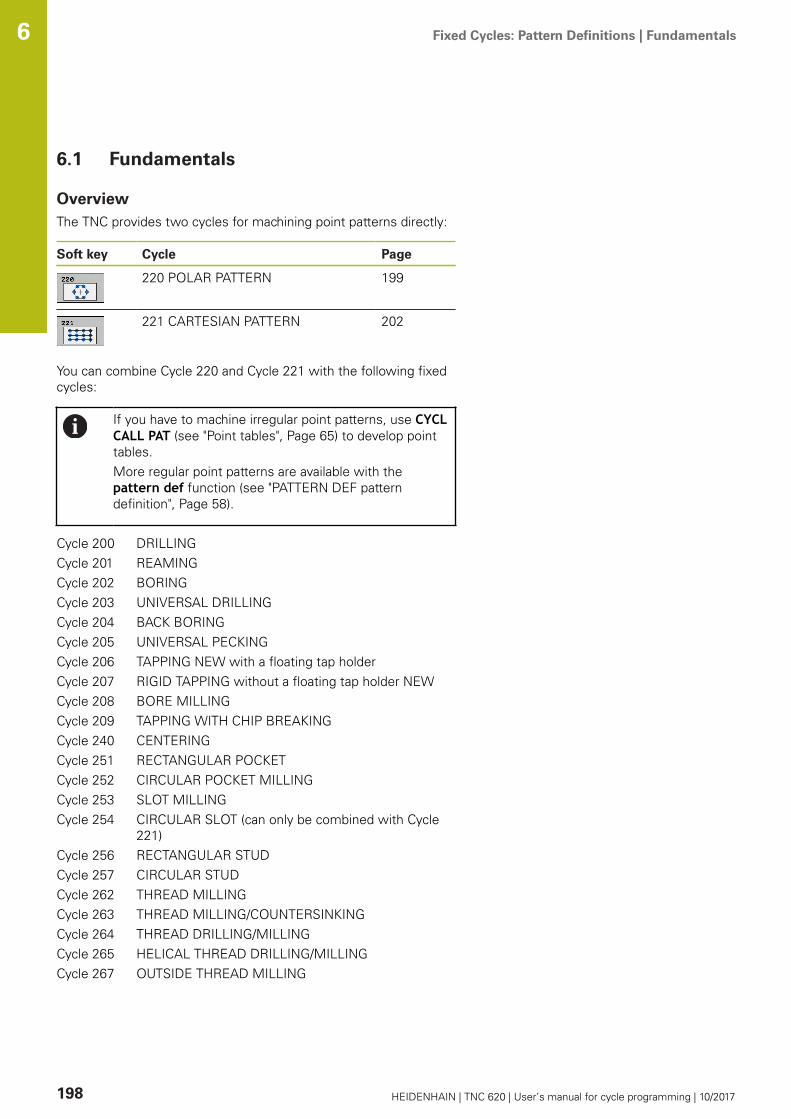
Fixed Cycles: Pattern Definitions | Fundamentals 6
198 HEIDENHAIN | TNC 620 | User’s manual for cycle programming | 10/2017
6.1 Fundamentals
OverviewThe TNC provides two cycles for machining point patterns directly:
Soft key Cycle Page
220 POLAR PATTERN 199
221 CARTESIAN PATTERN 202
You can combine Cycle 220 and Cycle 221 with the following fixedcycles:
If you have to machine irregular point patterns, use CYCLCALL PAT (see "Point tables", Page 65) to develop pointtables.More regular point patterns are available with thepattern def function (see "PATTERN DEF patterndefinition", Page 58).
Cycle 200 DRILLINGCycle 201 REAMINGCycle 202 BORINGCycle 203 UNIVERSAL DRILLINGCycle 204 BACK BORINGCycle 205 UNIVERSAL PECKINGCycle 206 TAPPING NEW with a floating tap holderCycle 207 RIGID TAPPING without a floating tap holder NEWCycle 208 BORE MILLINGCycle 209 TAPPING WITH CHIP BREAKINGCycle 240 CENTERINGCycle 251 RECTANGULAR POCKETCycle 252 CIRCULAR POCKET MILLINGCycle 253 SLOT MILLINGCycle 254 CIRCULAR SLOT (can only be combined with Cycle
221)Cycle 256 RECTANGULAR STUDCycle 257 CIRCULAR STUDCycle 262 THREAD MILLINGCycle 263 THREAD MILLING/COUNTERSINKINGCycle 264 THREAD DRILLING/MILLINGCycle 265 HELICAL THREAD DRILLING/MILLINGCycle 267 OUTSIDE THREAD MILLING
Fixed Cycles: Pattern Definitions | POLAR PATTERN (Cycle 220, DIN/ISO: G220, software option 19) 6
HEIDENHAIN | TNC 620 | User’s manual for cycle programming | 10/2017 199
6.2 POLAR PATTERN (Cycle 220, DIN/ISO:G220, software option 19)
Cycle run1 At rapid traverse, the TNC moves the tool from its current
position to the starting point for the first machining operation.Sequence:
Move to the 2nd set-up clearance (spindle axis)Approach the starting point in the spindle axis.Move to the set-up clearance above the workpiece surface(spindle axis)
2 From this position, the TNC executes the last defined fixedcycle.
3 The tool then approaches on a straight line or a circular arc thestarting point for the next machining operation. The tool stops atthe set-up clearance (or the 2nd set-up clearance).
4 This process (1 to 3) is repeated until all machining operationshave been executed.
Please note while programming:
Cycle 220 is DEF active, which means that Cycle 220automatically calls the last defined fixed cycle.If you combine Cycle 220 with one of the fixed cycles200 to 209 and 251 to 267 or with cycle 221, the set-up clearance, workpiece surface and the 2nd set-upclearance that were defined in Cycle 220 or 221 will beeffective. This applies in the program until the affectedparameters are overwritten again. Example: If in aprogram Cycle 200 is defined with Q203=0 and thena cycle 220 is programmed with Q203=-5, Q203=-5is used with the subsequent CYCL CALL and M99calls. Cycles 220 and 221 overwrite the above-specifiedparameters of the CALL-active machining cycles (withidentical input parameters in both cycles).If you run this cycle in the Single Block mode ofoperation, the control stops between the individualpoints of a point pattern.
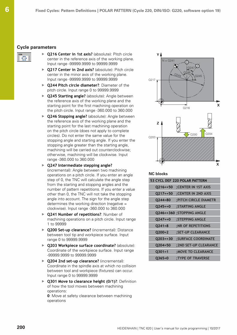
Fixed Cycles: Pattern Definitions | POLAR PATTERN (Cycle 220, DIN/ISO: G220, software option 19) 6
200 HEIDENHAIN | TNC 620 | User’s manual for cycle programming | 10/2017
Cycle parametersQ216 Center in 1st axis? (absolute): Pitch circlecenter in the reference axis of the working plane.Input range -99999.9999 to 99999.9999Q217 Center in 2nd axis? (absolute): Pitch circlecenter in the minor axis of the working plane.Input range -99999.9999 to 99999.9999Q244 Pitch circle diameter?: Diameter of thepitch circle. Input range 0 to 99999.9999Q245 Starting angle? (absolute): Angle betweenthe reference axis of the working plane and thestarting point for the first machining operation onthe pitch circle. Input range -360.000 to 360.000Q246 Stopping angle? (absolute): Angle betweenthe reference axis of the working plane and thestarting point for the last machining operationon the pitch circle (does not apply to completecircles). Do not enter the same value for thestopping angle and starting angle. If you enter thestopping angle greater than the starting angle,machining will be carried out counterclockwise;otherwise, machining will be clockwise. Inputrange -360.000 to 360.000Q247 Intermediate stepping angle?(incremental): Angle between two machiningoperations on a pitch circle. If you enter an anglestep of 0, the TNC will calculate the angle stepfrom the starting and stopping angles and thenumber of pattern repetitions. If you enter a valueother than 0, the TNC will not take the stoppingangle into account. The sign for the angle stepdetermines the working direction (negative =clockwise). Input range -360.000 to 360.000Q241 Number of repetitions?: Number ofmachining operations on a pitch circle. Input range1 to 99999Q200 Set-up clearance? (incremental): Distancebetween tool tip and workpiece surface. Inputrange 0 to 99999.9999Q203 Workpiece surface coordinate? (absolute):Coordinate of the workpiece surface. Input range-99999.9999 to 99999.9999Q204 2nd set-up clearance? (incremental):Coordinate in the spindle axis at which no collisionbetween tool and workpiece (fixtures) can occur.Input range 0 to 99999.9999Q301 Move to clearance height (0/1)?: Definitionof how the tool moves between machiningoperations:0: Move at safety clearance between machiningoperations
NC blocks
53 CYCL DEF 220 POLAR PATTERN
Q216=+50 ;CENTER IN 1ST AXIS
Q217=+50 ;CENTER IN 2ND AXIS
Q244=80 ;PITCH CIRCLE DIAMETR
Q245=+0 ;STARTING ANGLE
Q246=+360 ;STOPPING ANGLE
Q247=+0 ;STEPPING ANGLE
Q241=8 ;NR OF REPETITIONS
Q200=2 ;SET-UP CLEARANCE
Q203=+30 ;SURFACE COORDINATE
Q204=50 ;2ND SET-UP CLEARANCE
Q301=1 ;MOVE TO CLEARANCE
Q365=0 ;TYPE OF TRAVERSE
Fixed Cycles: Pattern Definitions | POLAR PATTERN (Cycle 220, DIN/ISO: G220, software option 19) 6
HEIDENHAIN | TNC 620 | User’s manual for cycle programming | 10/2017 201
1: Move at 2nd safety clearance betweenmachining operationsQ365 Type of traverse? Line=0/arc=1: Definitionof the path function with which the tool movesbetween machining operations:0: Move in a straight line between machiningoperations1: Move in a circular arc on the pitch circlediameter between machining operations

Fixed Cycles: Pattern Definitions | LINEAR PATTERN (Cycle 221, DIN/ISO: G221, software option 19) 6
202 HEIDENHAIN | TNC 620 | User’s manual for cycle programming | 10/2017
6.3 LINEAR PATTERN (Cycle 221, DIN/ISO:G221, software option 19)
Cycle run1 The TNC automatically moves the tool from its current position
to the starting point for the first machining operation.Sequence:
Move to the 2nd set-up clearance (spindle axis)Approach the starting point in the machining planeMove to the set-up clearance above the workpiece surface(spindle axis)
2 From this position, the TNC executes the last defined fixedcycle.
3 The tool then approaches the starting point for the nextmachining operation in the positive reference axis direction atset-up clearance (or 2nd set-up clearance).
4 This process (1 to 3) is repeated until all machining operationson the first line have been executed. The tool is located abovethe last point on the first line.
5 The tool subsequently moves to the last point on the secondline where it carries out the machining operation.
6 From this position, the tool approaches the starting point forthe next machining operation in the negative reference axisdirection.
7 This process (6) is repeated until all machining operations in thesecond line have been executed.
8 The tool then moves to the starting point of the next line.9 All subsequent lines are processed in a reciprocating
movement.
Please note while programming:
Cycle 221 is DEF active, which means that Cycle 221automatically calls the last defined fixed cycle.If you combine Cycle 221 with one of the fixed cycles200 to 209 and 251 to 267, the set-up clearance,workpiece surface, the 2nd set-up clearance, and therotational position that were defined in Cycle 221 will beeffective.The slot position 0 is not allowed if you use Cycle 254Circular Slot in combination with Cycle 221.If you run this cycle in the Single Block mode ofoperation, the control stops between the individualpoints of a point pattern.

Fixed Cycles: Pattern Definitions | LINEAR PATTERN (Cycle 221, DIN/ISO: G221, software option 19) 6
HEIDENHAIN | TNC 620 | User’s manual for cycle programming | 10/2017 203
Cycle parametersQ225 Starting point in 1st axis? (absolute):Coordinate of the starting point in the referenceaxis of the working planeQ226 Starting point in 2nd axis? (absolute):Coordinate of the starting point in the minor axisof the working planeQ237 Spacing in 1st axis? (incremental): Spacingbetween the individual points on a lineQ238 Spacing in 2nd axis? (incremental): Spacingbetween the individual linesQ242 Number of columns?: Number of machiningoperations on a lineQ243 Number of lines?: Number of linesQ224 Angle of rotation? (absolute): Angle bywhich the entire pattern is rotated. The center ofrotation lies in the starting pointQ200 Set-up clearance? (incremental): Distancebetween tool tip and workpiece surface. Inputrange 0 to 99999.9999Q203 Workpiece surface coordinate? (absolute):Coordinate of the workpiece surface. Input range-99999.9999 to 99999.9999Q204 2nd set-up clearance? (incremental):Coordinate in the spindle axis at which no collisionbetween tool and workpiece (fixtures) can occur.Input range 0 to 99999.9999Q301 Move to clearance height (0/1)?: Definitionof how the tool moves between machiningoperations:0: Move at safety clearance between machiningoperations1: Move at 2nd safety clearance betweenmachining operations
NC blocks
54 CYCL DEF 221 CARTESIAN PATTERN
Q225=+15 ;STARTNG PNT 1ST AXIS
Q226=+15 ;STARTNG PNT 2ND AXIS
Q237=+10 ;SPACING IN 1ST AXIS
Q238=+8 ;SPACING IN 2ND AXIS
Q242=6 ;NUMBER OF COLUMNS
Q243=4 ;NUMBER OF LINES
Q224=+15 ;ANGLE OF ROTATION
Q200=2 ;SET-UP CLEARANCE
Q203=+30 ;SURFACE COORDINATE
Q204=50 ;2ND SET-UP CLEARANCE
Q301=1 ;MOVE TO CLEARANCE

Fixed Cycles: Pattern Definitions | Programming Examples 6
204 HEIDENHAIN | TNC 620 | User’s manual for cycle programming | 10/2017
6.4 Programming Examples
Example: Polar hole patterns
0 BEGIN PGM HOLEPAT MM
1 BLK FORM 0.1 Z X+0 Y+0 Z-40 Definition of workpiece blank
2 BLK FORM 0.2 X+100 Y+100 Z+0
3 TOOL CALL 1 Z S3500 Tool call
4 L Z+250 R0 FMAX M3 Retract the tool
5 CYCL DEF 200 DRILLING Cycle definition: drilling
Q200=2 ;SET-UP CLEARANCE
Q201=-15 ;DEPTH
Q206=250 ;FEED RATE FOR PLNGNG
Q202=4 ;PLUNGING DEPTH
Q211=0 ;DWELL TIME AT TOP
Q203=+0 ;SURFACE COORDINATE
Q204=0 ;2ND SET-UP CLEARANCE
Q211=0.25 ;DWELL TIME AT DEPTH
Q395=0 ;DEPTH REFERENCE
6 CYCL DEF 220 POLAR PATTERN Define cycle for polar pattern 1, CYCL 200 is calledautomatically; Q200, Q203 and Q204 are effective asdefined in Cycle 220.
Q216=+30 ;CENTER IN 1ST AXIS
Q217=+70 ;CENTER IN 2ND AXIS
Q244=50 ;PITCH CIRCLE DIAMETR
Q245=+0 ;STARTING ANGLE
Q246=+360 ;STOPPING ANGLE
Q247=+0 ;STEPPING ANGLE
Q241=10 ;NR OF REPETITIONS
Q200=2 ;SET-UP CLEARANCE
Q203=+0 ;SURFACE COORDINATE

Fixed Cycles: Pattern Definitions | Programming Examples 6
HEIDENHAIN | TNC 620 | User’s manual for cycle programming | 10/2017 205
Q204=100 ;2ND SET-UP CLEARANCE
Q301=1 ;MOVE TO CLEARANCE
Q365=0 ;TYPE OF TRAVERSE
7 CYCL DEF 220 POLAR PATTERN Define cycle for polar pattern 2, CYCL 200 is calledautomatically; Q200, Q203 and Q204 are effective asdefined in Cycle 220.
Q216=+90 ;CENTER IN 1ST AXIS
Q217=+25 ;CENTER IN 2ND AXIS
Q244=70 ;PITCH CIRCLE DIAMETR
Q245=+90 ;STARTING ANGLE
Q246=+360 ;STOPPING ANGLE
Q247=+30 ;STEPPING ANGLE
Q241=5 ;NR OF REPETITIONS
Q200=2 ;SET-UP CLEARANCE
Q203=+0 ;SURFACE COORDINATE
Q204=100 ;2ND SET-UP CLEARANCE
Q301=1 ;MOVE TO CLEARANCE
Q365=0 ;TYPE OF TRAVERSE
8 L Z+250 R0 FMAX M2 Retract in the tool axis, end program
9 END PGM HOLEPAT MM


7Fixed Cycles:
Contour Pocket
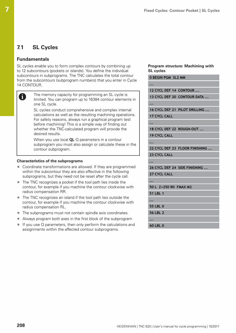
Fixed Cycles: Contour Pocket | SL Cycles 7
208 HEIDENHAIN | TNC 620 | User’s manual for cycle programming | 10/2017
7.1 SL Cycles
FundamentalsSL cycles enable you to form complex contours by combining upto 12 subcontours (pockets or islands). You define the individualsubcontours in subprograms. The TNC calculates the total contourfrom the subcontours (subprogram numbers) that you enter in Cycle14 CONTOUR.
The memory capacity for programming an SL cycle islimited. You can program up to 16384 contour elements inone SL cycle.SL cycles conduct comprehensive and complex internalcalculations as well as the resulting machining operations.For safety reasons, always run a graphical program testbefore machining! This is a simple way of finding outwhether the TNC-calculated program will provide thedesired results.When you use local QL Q parameters in a contoursubprogram you must also assign or calculate these in thecontour subprogram.
Characteristics of the subprograms
Coordinate transformations are allowed. If they are programmedwithin the subcontour they are also effective in the followingsubprograms, but they need not be reset after the cycle call.The TNC recognizes a pocket if the tool path lies inside thecontour, for example if you machine the contour clockwise withradius compensation RR.The TNC recognizes an island if the tool path lies outside thecontour, for example if you machine the contour clockwise withradius compensation RL.The subprograms must not contain spindle axis coordinates.Always program both axes in the first block of the subprogramIf you use Q parameters, then only perform the calculations andassignments within the affected contour subprograms.
Program structure: Machining withSL cycles
0 BEGIN PGM SL2 MM
...
12 CYCL DEF 14 CONTOUR ...
13 CYCL DEF 20 CONTOUR DATA ...
...
16 CYCL DEF 21 PILOT DRILLING ...
17 CYCL CALL
...
18 CYCL DEF 22 ROUGH-OUT ...
19 CYCL CALL
...
22 CYCL DEF 23 FLOOR FINISHING ...
23 CYCL CALL
...
26 CYCL DEF 24 SIDE FINISHING ...
27 CYCL CALL
...
50 L Z+250 R0 FMAX M2
51 LBL 1
...
55 LBL 0
56 LBL 2
...
60 LBL 0

Fixed Cycles: Contour Pocket | SL Cycles 7
HEIDENHAIN | TNC 620 | User’s manual for cycle programming | 10/2017 209
Characteristics of the fixed cycles
The TNC automatically positions the tool to the set-up clearancebefore each cycle. You must move the tool to a safe positionbefore the cycle call.Each level of infeed depth is milled without interruptions since thecutter traverses around islands instead of over them.The radius of "inside corners" can be programmed—the toolkeeps moving to prevent surface blemishes at inside corners (thisapplies to the outermost pass in the Rough-out and Side Finishingcycles).The contour is approached in a tangential arc for side finishing.For floor finishing, the tool again approaches the workpiece on atangential arc (for spindle axis Z, for example, the arc may be inthe Z/X plane).The contour is machined throughout in either climb or up-cutmilling.
The machining data (such as milling depth, finishing allowance andset-up clearance) are entered as CONTOUR DATA in Cycle 20.
...
99 END PGM SL2 MM
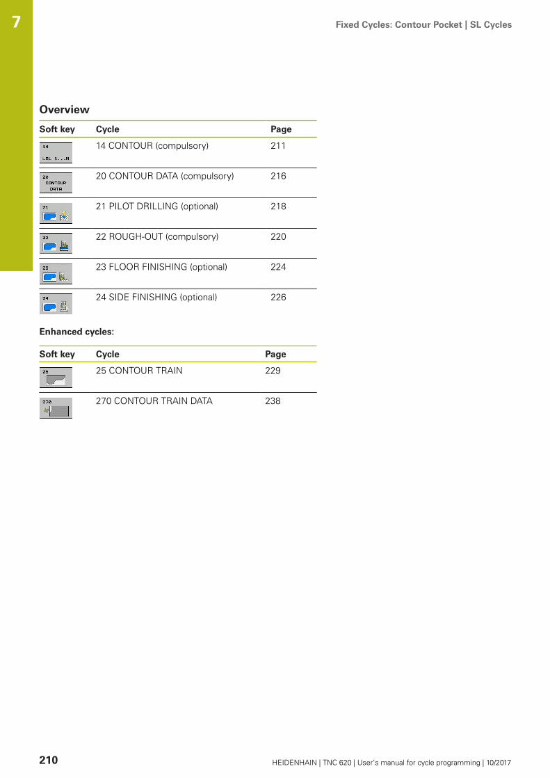
Fixed Cycles: Contour Pocket | SL Cycles 7
210 HEIDENHAIN | TNC 620 | User’s manual for cycle programming | 10/2017
Overview
Soft key Cycle Page
14 CONTOUR (compulsory) 211
20 CONTOUR DATA (compulsory) 216
21 PILOT DRILLING (optional) 218
22 ROUGH-OUT (compulsory) 220
23 FLOOR FINISHING (optional) 224
24 SIDE FINISHING (optional) 226
Enhanced cycles:
Soft key Cycle Page
25 CONTOUR TRAIN 229
270 CONTOUR TRAIN DATA 238

Fixed Cycles: Contour Pocket | CONTOUR (Cycle 14, DIN/ISO: G37) 7
HEIDENHAIN | TNC 620 | User’s manual for cycle programming | 10/2017 211
7.2 CONTOUR (Cycle 14, DIN/ISO: G37)
Please note while programming:All subprograms that are superimposed to define the contour arelisted in Cycle 14 CONTOUR.
Cycle 14 is DEF active which means that it becomeseffective as soon as it is defined in the part program.You can list up to 12 subprograms (subcontours) in Cycle14.
Cycle parametersLabel numbers for the contour: Enter all labelnumbers for the individual subprograms thatare to be superimposed to define the contour.Confirm every label number with the ENT key.When you have entered all numbers, concludeentry with the END key. Entry of up to 12subprogram numbers 1 to 65535.

Fixed Cycles: Contour Pocket | Superimposed contours 7
212 HEIDENHAIN | TNC 620 | User’s manual for cycle programming | 10/2017
7.3 Superimposed contours
FundamentalsPockets and islands can be overlapped to form a new contour. Youcan thus enlarge the area of a pocket by another pocket or reduce itby an island.
NC blocks
12 CYCL DEF 14.0 CONTOUR
13 CYCL DEF 14.1 CONTOURLABEL1/2/3/4
Subprograms: overlapping pockets
The subsequent programming examples are contoursubprograms that are called by Cycle 14 CONTOUR in amain program.
Pockets A and B overlap.The TNC calculates the points of intersection S1 and S2. They neednot be programmed.The pockets are programmed as full circles.
Subprogram 1: Pocket A
51 LBL 1
52 L X+10 Y+50 RR
53 CC X+35 Y+50
54 C X+10 Y+50 DR-
55 LBL 0
Subprogram 2: Pocket B
56 LBL 2
57 L X+90 Y+50 RR
58 CC X+65 Y+50
59 C X+90 Y+50 DR-
60 LBL 0

Fixed Cycles: Contour Pocket | Superimposed contours 7
HEIDENHAIN | TNC 620 | User’s manual for cycle programming | 10/2017 213
Area of inclusionBoth surfaces A and B are to be machined, including theoverlapping area:
The surfaces A and B must be pockets.The first pocket (in Cycle 14) must start outside the secondpocket.
Surface A:
51 LBL 1
52 L X+10 Y+50 RR
53 CC X+35 Y+50
54 C X+10 Y+50 DR-
55 LBL 0
Surface B:
56 LBL 2
57 L X+90 Y+50 RR
58 CC X+65 Y+50
59 C X+90 Y+50 DR-
60 LBL 0

Fixed Cycles: Contour Pocket | Superimposed contours 7
214 HEIDENHAIN | TNC 620 | User’s manual for cycle programming | 10/2017
Area of exclusionSurface A is to be machined without the portion overlapped by B:
Surface A must be a pocket and B an island.A must start outside of B.B must start inside of A.
Surface A:
51 LBL 1
52 L X+10 Y+50 RR
53 CC X+35 Y+50
54 C X+10 Y+50 DR-
55 LBL 0
Surface B:
56 LBL 2
57 L X+40 Y+50 RL
58 CC X+65 Y+50
59 C X+40 Y+50 DR-
60 LBL 0

Fixed Cycles: Contour Pocket | Superimposed contours 7
HEIDENHAIN | TNC 620 | User’s manual for cycle programming | 10/2017 215
Area of intersectionOnly the area where A and B overlap is to be machined. (The areascovered by A or B alone are to be left unmachined.)
A and B must be pockets.A must start inside of B.
Surface A:
51 LBL 1
52 L X+60 Y+50 RR
53 CC X+35 Y+50
54 C X+60 Y+50 DR-
55 LBL 0
Surface B:
56 LBL 2
57 L X+90 Y+50 RR
58 CC X+65 Y+50
59 C X+90 Y+50 DR-
60 LBL 0

Fixed Cycles: Contour Pocket | CONTOUR DATA (Cycle 20, DIN/ISO: G120, software option 19) 7
216 HEIDENHAIN | TNC 620 | User’s manual for cycle programming | 10/2017
7.4 CONTOUR DATA (Cycle 20, DIN/ISO:G120, software option 19)
Please note while programming:Machining data for the subprograms describing the subcontoursare entered in Cycle 20.
Cycle 20 is DEF active, which means that it becomeseffective as soon as it is defined in the part program.The machining data entered in Cycle 20 are valid forCycles 21 to 24.The algebraic sign for the cycle parameter DEPTHdetermines the working direction. If you programDEPTH = 0, the TNC performs the cycle at the depth 0.If you are using the SL cycles in Q parameter programs,the cycle parameters Q1 to Q20 cannot be used asprogram parameters.

Fixed Cycles: Contour Pocket | CONTOUR DATA (Cycle 20, DIN/ISO: G120, software option 19) 7
HEIDENHAIN | TNC 620 | User’s manual for cycle programming | 10/2017 217
Cycle parametersQ1 Milling depth? (incremental): Distancebetween workpiece surface and bottom of pocket.Input range -99999.9999 to 99999.9999Q2 Path overlap factor?: Q2 x tool radius =stepover factor k. Input range: -0.0001 to 1.9999Q3 Finishing allowance for side? (incremental):Finishing allowance in the machining plane. Inputrange -99999.9999 to 99999.9999Q4 Finishing allowance for floor? (incremental):Finishing allowance for the floor. Input range-99999.9999 to 99999.9999Q5 Workpiece surface coordinate? (absolute):Absolute coordinate of the workpiece surface.Input range -99999.9999 to 99999.9999Q6 Set-up clearance? (incremental): Distancebetween tool tip and workpiece surface. Inputrange 0 to 99999.9999Q7 Clearance height? (absolute): Absolute heightat which the tool cannot collide with the workpiece(for intermediate positioning and retraction at theend of the cycle). Input range -99999.9999 to99999.9999Q8 Inside corner radius?: Inside "corner" roundingradius; entered value is referenced to the path ofthe tool center and is used to calculate smoothertraverse motions between the contour elements.Q8 is not a radius that is inserted as a separatecontour element between programmedelements! Input range 0 to 99999.9999Q9 Direction of rotation? cw = -1: Machiningdirection for pockets
Q9 = –1 up-cut milling for pocket and islandQ9 = +1 climb milling for pocket and island
You can check the machining parameters during a programinterruption and overwrite them if required.
NC blocks
57 CYCL DEF 20 CONTOUR DATA
Q1=-20 ;MILLING DEPTH
Q2=1 ;TOOL PATH OVERLAP
Q3=+0.2 ;ALLOWANCE FOR SIDE
Q4=+0.1 ;ALLOWANCE FOR FLOOR
Q5=+30 ;SURFACE COORDINATE
Q6=2 ;SET-UP CLEARANCE
Q7=+80 ;CLEARANCE HEIGHT
Q8=0.5 ;ROUNDING RADIUS
Q9=+1 ;ROTATIONAL DIRECTION

Fixed Cycles: Contour Pocket | PILOT DRILLING (Cycle 21, DIN/ISO: G121, software option 19) 7
218 HEIDENHAIN | TNC 620 | User’s manual for cycle programming | 10/2017
7.5 PILOT DRILLING (Cycle 21, DIN/ISO:G121, software option 19)
Cycle runYou use Cycle 21 PILOT DRILLING if you subsequently do not usea center-cut end mill (ISO 1641) for clearing out your contour. Thiscycle drills a hole in the area that is to be roughed out with a cyclesuch as Cycle 22. Cycle 21 takes the allowance for side and theallowance for floor as well as the radius of the rough-out tool intoaccount for the cutter infeed points. The cutter infeed points alsoserve as starting points for roughing.Before calling Cycle 21 you need to program two further cycles:
Cycle 14 CONTOUR or SEL CONTOUR—needed by Cycle 21PILOT DRILLING in order to determine the drilling position inthe planeCycle 20 CONTOUR DATA—needed by Cycle 21 PILOTDRILLING in order to determine parameters such as hole depthand set-up clearance
Cycle run:1 The TNC first positions the tool in the plane (the position
results from the contour you have defined with Cycle 14 or SELCONTOUR, and from the rough-out tool data).
2 The tool then moves at rapid traverse FMAX to the set-upclearance. (Define the set-up clearance in Cycle 20 CONTOURDATA).
3 The tool drills from the current position to the first plungingdepth at the programmed feed rate F.
4 Then the tool retracts at rapid traverse FMAX to the startingposition and advances again to the first plunging depth minusthe advanced stop distance t.
5 The advanced stop distance is automatically calculated by thecontrol:
At a total hole depth up to 30 mm: t = 0.6 mmAt a total hole depth exceeding 30 mm: t = hole depth / 50Maximum advanced stop distance: 7 mm
6 The tool then advances with another infeed at the programmedfeed rate F.
7 The TNC repeats this process (1 to 4) until the programmedtotal hole depth is reached. The finishing allowance for floor istaken into account.
8 Finally, the tool retracts in the tool axis to the clearanceheight or to the position last programmed before the cycle.This depends on the parameter ConfigDatum, CfgGeoCycle,posAfterContPocket.

Fixed Cycles: Contour Pocket | PILOT DRILLING (Cycle 21, DIN/ISO: G121, software option 19) 7
HEIDENHAIN | TNC 620 | User’s manual for cycle programming | 10/2017 219
Please note while programming:
When calculating the infeed points, the TNC does notaccount for the delta value DR programmed in a TOOLCALL block.In narrow areas, the TNC may not be able to carry outpilot drilling with a tool that is larger than the rough-outtool.If Q13=0, the TNC uses the data of the tool that iscurrently in the spindle.After the end of the cycle, do not position thetool in the plane incrementally, but rather to anabsolute position if you have set the ConfigDatum> CfgGeoCycle > posAfterContPocket parameter toToolAxClearanceHeight.
Cycle parametersQ10 Plunging depth? (incremental): Dimensionby which the tool drills in each infeed (minussign for negative working direction). Input range-99999.9999 to 99999.9999Q11 Feed rate for plunging?: Traversing speed ofthe tool in mm/min while plunging. Input range 0to 99999.9999, alternatively FAUTO, fu, FZQ13 Rough-out tool number/name? or QS13:Number or name of rough-out tool. You are ableto apply the tool via soft key directly from the tooltable.
NC blocks
58 CYCL DEF 21 PILOT DRILLING
Q10=+5 ;PLUNGING DEPTH
Q11=100 ;FEED RATE FOR PLNGNG
Q13=1 ;ROUGH-OUT TOOL

Fixed Cycles: Contour Pocket | ROUGHING (Cycle 22, DIN/ISO: G122, software option 19) 7
220 HEIDENHAIN | TNC 620 | User’s manual for cycle programming | 10/2017
7.6 ROUGHING (Cycle 22, DIN/ISO: G122,software option 19)
Cycle runUse Cycle 22 ROUGHING to define the technology data forroughing.Before calling Cycle 22 you need to program further cycles:
Cycle 14 CONTOUR or SEL CONTOURCycle 20 CONTOUR DATACycle 21 PILOT DRILLING, if necessary
Cycle run1 The TNC positions the tool over the cutter infeed point, taking
the allowance for side into account.2 In the first plunging depth, the tool mills the contour from inside
outward at the milling feed rate.3 First the island contours (C and D in the figure at right) are
rough-milled until the pocket contour (A, B) is approached.4 In the next step the TNC moves the tool to the next plunging
depth and repeats the roughing procedure until the programdepth is reached.
5 Finally, the tool retracts in the tool axis to the clearanceheight or to the position last programmed before the cycle.This depends on the parameter ConfigDatum, CfgGeoCycle,posAfterContPocket.

Fixed Cycles: Contour Pocket | ROUGHING (Cycle 22, DIN/ISO: G122, software option 19) 7
HEIDENHAIN | TNC 620 | User’s manual for cycle programming | 10/2017 221
Please note while programming:
This cycle requires a center-cut end mill (ISO 1641) orpilot drilling with Cycle 21.You define the plunging behavior of Cycle 22 withparameter Q19 and with the tool table in the ANGLE andLCUTS columns:
If Q19=0 is defined, the TNC always plungesperpendicularly, even if a plunge angle (ANGLE) isdefined for the active tool.If you define the ANGLE=90°, the TNC plungesperpendicularly. The reciprocation feed rate Q19 isused as plunging feed rate.If the reciprocation feed rate Q19 is defined in Cycle22 and ANGLE is defined between 0.1 and 89.999in the tool table, the TNC plunges helically at thedefined ANGLE.If the reciprocation feed is defined in Cycle 22 and noANGLE is in the tool table, the TNC displays an errormessage.If geometrical conditions do not allow helicalplunging (slot), the TNC tries a reciprocating plunge.The reciprocation length is calculated from LCUTSand ANGLE (reciprocation length = LCUTS / tanANGLE).
If you clear out an acute inside corner and use anoverlap factor greater than 1, some material might beleft over. Check especially the innermost path in the testrun graphic and, if necessary, change the overlap factorslightly. This allows another distribution of cuts, whichoften provides the desired results.During fine roughing the TNC does not take a definedwear value DR of the coarse roughing tool into account.If M110 is activated during operation, the feed rateof compensated circular arcs within will be reducedaccordingly.
NOTICEDanger of collision!
If you set the parameter posAfterContPocket toToolAxClearanceHeight, the TNC positions the tool after the endof the cycle only in the tool axis direction to the clearance height.The TNC does not position the tool in the working plane.
After the end of the cycle, position the tool with allcoordinates of the working plane, e.g. L X+80 Y+0 R0 FMAX
After the cycle, program the absolute position (not anincremental traversing movement)

Fixed Cycles: Contour Pocket | ROUGHING (Cycle 22, DIN/ISO: G122, software option 19) 7
222 HEIDENHAIN | TNC 620 | User’s manual for cycle programming | 10/2017
Cycle parametersQ10 Plunging depth? (incremental): Infeed percut. Input range -99999.9999 to 99999.9999Q11 Feed rate for plunging?: Traversing speedof the tool in the spindle axis. Input range 0 to99999.9999, alternatively FAUTO, fu, FZQ12 Feed rate for roughing?: Traversing speedof the tool in the working plane. Input range 0 to99999.9999, alternatively FAUTO, fu, FZQ18 Coarse roughing tool? or QS18: Number orname of the tool with which the TNC has alreadycoarse-roughed the contour. You are able to applythe coarse roughing tool via soft key directlyfrom the tool table. In addition, you can enterthe tool name via the soft key tool name. TheTNC automatically inserts the closing quotationmark when you exit the input field. If there wasno coarse roughing, enter "0"; if you enter anumber or a name, the TNC will only rough-out the portion that could not be machined withthe coarse roughing tool. If the portion that isto be roughed cannot be approached from theside, the TNC will mill in a reciprocating plunge-cut; for this purpose you must enter the toollength LCUTS in the tool table TOOL.T and definethe maximum plunging ANGLE of the tool. TheTNC will otherwise generate an error message.Input range 0 to 99999 if a number is entered;maximum 16 characters if a name is entered.Q19 Feed rate for reciprocation?: Reciprocationfeed rate in mm/min. Input range 0 to 99999.9999,alternatively FAUTO, fu, FZQ208 Feed rate for retraction?: Traversing speedof the tool in mm/min when retracting after themachining operation. If you enter Q208 = 0, theTNC retracts the tool at the feed rate Q12. Inputrange 0 to 99999.9999, alternatively fmax,FAUTO
NC blocks
59 CYCL DEF 22 ROUGH-OUT
Q10=+5 ;PLUNGING DEPTH
Q11=100 ;FEED RATE FOR PLNGNG
Q12=750 ;FEED RATE F. ROUGHNG
Q18=1 ;COARSE ROUGHINGTOOL
Q19=150 ;FEED RATE FOR RECIP.
Q208=9999 ;RETRACTION FEED RATE
Q401=80 ;FEED RATE FACTOR
Q404=0 ;FINE ROUGH STRATEGY

Fixed Cycles: Contour Pocket | ROUGHING (Cycle 22, DIN/ISO: G122, software option 19) 7
HEIDENHAIN | TNC 620 | User’s manual for cycle programming | 10/2017 223
Q401 Feed rate factor in %?: Percentage factorby which the TNC reduces the machining feedrate (Q12) as soon as the tool moves within thematerial over its entire circumference duringroughing. If you use the feed rate reduction,then you can define the feed rate for roughing solarge that there are optimum cutting conditionswith the path overlap (Q2) specified in Cycle 20.The TNC then reduces the feed rate as per yourdefinition at transitions and narrow places, so themachining time should be reduced in total. Inputrange 0.0001 to 100.0000Q404 Fine roughing strategy (0/1)?: Specify thefine roughing behavior of the TNC if the radius ofthe fine roughing tool is identical or greater thanhalf the radius of the rough-out tool.Q404=0: The TNC moves the tool between the areas tobe fine roughed at the current depth along thecontourQ404=1: The TNC retracts the tool to the set-up clearancebetween the areas to be fine roughed and thenmoves to the starting point for the next area to beroughed out
Fixed Cycles: Contour Pocket | FLOOR FINISHING (Cycle 23, DIN/ISO: G123, software option 19) 7
224 HEIDENHAIN | TNC 620 | User’s manual for cycle programming | 10/2017
7.7 FLOOR FINISHING (Cycle 23, DIN/ISO:G123, software option 19)
Cycle runWith Cycle 23 FLOOR FINISHING, you can clear the finishingallowance for floor that is programmed in Cycle 20. The toolapproaches the machining plane smoothly (on a vertically tangentialarc) if there is sufficient room. If there is not enough room, the TNCmoves the tool to depth vertically. The tool then clears the finishingallowance remaining from rough-out.Before calling Cycle 23 you need to program further cycles:
Cycle 14 CONTOUR or SEL CONTOURCycle 20 CONTOUR DATACycle 21 PILOT DRILLING, if necessaryCycle 22 ROUGHING, if necessary
Cycle run1 The TNC positions the tool to the clearance height at rapid
traverse FMAX.2 The tool then moves in the tool axis at the feed rate Q11.3 The tool approaches the machining plane smoothly (on a
vertically tangential arc) if there is sufficient room. If there is notenough room, the TNC moves the tool to depth vertically.
4 The tool clears the finishing allowance remaining from rough-out.
5 Finally, the tool retracts in the tool axis to the clearanceheight or to the position last programmed before the cycle.This depends on the parameter ConfigDatum, CfgGeoCycle,posAfterContPocket.

Fixed Cycles: Contour Pocket | FLOOR FINISHING (Cycle 23, DIN/ISO: G123, software option 19) 7
HEIDENHAIN | TNC 620 | User’s manual for cycle programming | 10/2017 225
Please note while programming:
The TNC automatically calculates the starting point forfinishing. The starting point depends on the availablespace in the pocket.The approaching radius for pre-positioning to the finaldepth is permanently defined and independent of theplunging angle of the tool.If M110 is activated during operation, the feed rateof compensated circular arcs within will be reducedaccordingly.
NOTICEDanger of collision!
If you set the parameter posAfterContPocket toToolAxClearanceHeight, the TNC positions the tool after the endof the cycle only in the tool axis direction to the clearance height.The TNC does not position the tool in the working plane.
After the end of the cycle, position the tool with allcoordinates of the working plane, e.g. L X+80 Y+0 R0 FMAX
After the cycle, program the absolute position (not anincremental traversing movement)
Cycle parametersQ11 Feed rate for plunging?: Traversing speed ofthe tool in mm/min while plunging. Input range 0to 99999.9999, alternatively FAUTO, fu, FZQ12 Feed rate for roughing?: Traversing speedof the tool in the working plane. Input range 0 to99999.9999, alternatively FAUTO, fu, FZQ208 Feed rate for retraction?: Traversing speedof the tool in mm/min when retracting after themachining operation. If you enter Q208 = 0, theTNC retracts the tool at the feed rate Q12. Inputrange 0 to 99999.9999, alternatively fmax,FAUTO NC blocks
60 CYCL DEF 23 FLOOR FINISHING
Q11=100 ;FEED RATE FOR PLNGNG
Q12=350 ;FEED RATE F. ROUGHNG
Q208=9999 ;RETRACTION FEED RATE

Fixed Cycles: Contour Pocket | SIDE FINISHING (Cycle 24, DIN/ISO: G124, software option 19) 7
226 HEIDENHAIN | TNC 620 | User’s manual for cycle programming | 10/2017
7.8 SIDE FINISHING (Cycle 24, DIN/ISO:G124, software option 19)
Cycle runWith Cycle 24 SIDE FINISHING, you can clear the finishingallowance for side that is programmed in Cycle 20. You can run thiscycle in climb or up-cut milling.Before calling Cycle 24 you need to program further cycles:
Cycle 14 CONTOUR or SEL CONTOURCycle 20 CONTOUR DATACycle 21 PILOT DRILLING, if necessaryCycle 22 ROUGHING, if necessary
Cycle run1 The TNC positions the tool above the workpiece surface to the
starting point for the approach position. This position in theplane results from a tangential arc on which the TNC moves thetool when approaching the contour.
2 The tool then advances to the first plunging depth at the feedrate for plunging.
3 The contour is approached on a tangential arc until the entirecontour is completed. Each subcontour is finished separately.
4 Finally, the tool retracts in the tool axis to the clearanceheight or to the position last programmed before the cycle.This depends on the parameter ConfigDatum, CfgGeoCycle,posAfterContPocket.

Fixed Cycles: Contour Pocket | SIDE FINISHING (Cycle 24, DIN/ISO: G124, software option 19) 7
HEIDENHAIN | TNC 620 | User’s manual for cycle programming | 10/2017 227
Please note while programming:
The sum of allowance for side (Q14) and the radiusof the finish mill must be smaller than the sum ofallowance for side (Q3, Cycle 20) and the radius of therough mill.If no allowance has been defined in Cycle 20, the controlissues the error message "Tool radius too large".The allowance for side Q14 is left over after finishing.Therefore, it must be smaller than the allowance inCycle 20.This calculation also holds if you run Cycle 24 withouthaving roughed out with Cycle 22; in this case, enter "0"for the radius of the rough mill.You can use Cycle 24 also for contour milling. Then youmust:
define the contour to be milled as a single island(without pocket limit), andenter the finishing allowance (Q3) in Cycle 20 to begreater than the sum of the finishing allowance Q14+ radius of the tool being used
The TNC automatically calculates the starting point forfinishing. The starting point depends on the availablespace in the pocket and the allowance programmed inCycle 20.The starting point calculated by the TNC also dependson the machining sequence. If you select the finishingcycle with the GOTO key and then start the program,the starting point can be at a different location fromwhere it would be if you execute the program in thedefined sequence.If M110 is activated during operation, the feed rateof compensated circular arcs within will be reducedaccordingly.
NOTICEDanger of collision!
If you set the parameter posAfterContPocket toToolAxClearanceHeight, the TNC positions the tool after the endof the cycle only in the tool axis direction to the clearance height.The TNC does not position the tool in the working plane.
After the end of the cycle, position the tool with allcoordinates of the working plane, e.g. L X+80 Y+0 R0 FMAX
After the cycle, program the absolute position (not anincremental traversing movement)

Fixed Cycles: Contour Pocket | SIDE FINISHING (Cycle 24, DIN/ISO: G124, software option 19) 7
228 HEIDENHAIN | TNC 620 | User’s manual for cycle programming | 10/2017
Cycle parametersQ9 Direction of rotation? cw = -1: Machiningdirection: +1: Rotation counterclockwise –1: Rotation clockwiseQ10 Plunging depth? (incremental): Infeed percut. Input range -99999.9999 to 99999.9999Q11 Feed rate for plunging?: Traversing speed ofthe tool in mm/min while plunging. Input range 0to 99999.9999, alternatively FAUTO, fu, FZQ12 Feed rate for roughing?: Traversing speedof the tool in the working plane. Input range 0 to99999.9999, alternatively FAUTO, fu, FZQ14 Finishing allowance for side? (incremental):The allowance for side Q14 is left over afterfinishing. (This allowance must be smaller than theallowance in Cycle 20.) Input range -99999.9999 to99999.9999
NC blocks
61 CYCL DEF 24 SIDE FINISHING
Q9=+1 ;ROTATIONAL DIRECTION
Q10=+5 ;PLUNGING DEPTH
Q11=100 ;FEED RATE FOR PLNGNG
Q12=350 ;FEED RATE F. ROUGHNG
Q14=+0 ;ALLOWANCE FOR SIDE

Fixed Cycles: Contour Pocket | CONTOUR TRAIN (Cycle 25, DIN/ISO: G125, software option 19) 7
HEIDENHAIN | TNC 620 | User’s manual for cycle programming | 10/2017 229
7.9 CONTOUR TRAIN (Cycle 25, DIN/ISO:G125, software option 19)
Cycle runIn conjunction with Cycle 14 CONTOUR, this cycle facilitates themachining of open and closed contours.Cycle 25 CONTOUR TRAIN offers considerable advantages overmachining a contour using positioning blocks:
The TNC monitors the operation to prevent undercuts andsurface blemishes. It is recommended that you run a graphicsimulation of the contour before execution.If the radius of the selected tool is too large, the corners of thecontour may have to be reworked.The contour can be machined throughout by up-cut or by climbmilling. The type of milling even remains effective when thecontours are mirrored.The tool can traverse back and forth for milling in severalinfeeds: This results in faster machining.Allowance values can be entered in order to perform repeatedrough-milling and finish-milling operations.

Fixed Cycles: Contour Pocket | CONTOUR TRAIN (Cycle 25, DIN/ISO: G125, software option 19) 7
230 HEIDENHAIN | TNC 620 | User’s manual for cycle programming | 10/2017
Please note while programming:
The algebraic sign for the cycle parameter DEPTHdetermines the working direction. If you programDEPTH=0, the cycle will not be executed.The TNC takes only the first label of Cycle 14 CONTOURinto account.The sub program allows no APPR or DEP motions.When you use local QL Q parameters in a contoursubprogram you must also assign or calculate these inthe contour subprogram.The memory capacity for programming an SL cycle islimited. You can program up to 16384 contour elementsin one SL cycle.Cycle 20 CONTOUR DATA is not required.If M110 is activated during operation, the feed rateof compensated circular arcs within will be reducedaccordingly.
NOTICEDanger of collision!
If you set the parameter posAfterContPocket toToolAxClearanceHeight, the TNC positions the tool after the endof the cycle only in the tool axis direction to the clearance height.The TNC does not position the tool in the working plane.
After the end of the cycle, position the tool with allcoordinates of the working plane, e.g. L X+80 Y+0 R0 FMAX
After the cycle, program the absolute position (not anincremental traversing movement)
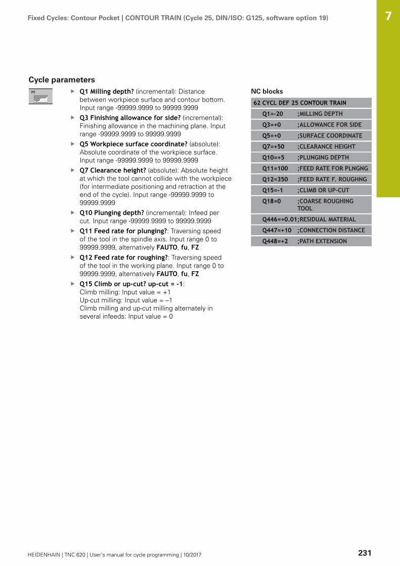
Fixed Cycles: Contour Pocket | CONTOUR TRAIN (Cycle 25, DIN/ISO: G125, software option 19) 7
HEIDENHAIN | TNC 620 | User’s manual for cycle programming | 10/2017 231
Cycle parametersQ1 Milling depth? (incremental): Distancebetween workpiece surface and contour bottom.Input range -99999.9999 to 99999.9999Q3 Finishing allowance for side? (incremental):Finishing allowance in the machining plane. Inputrange -99999.9999 to 99999.9999Q5 Workpiece surface coordinate? (absolute):Absolute coordinate of the workpiece surface.Input range -99999.9999 to 99999.9999Q7 Clearance height? (absolute): Absolute heightat which the tool cannot collide with the workpiece(for intermediate positioning and retraction at theend of the cycle). Input range -99999.9999 to99999.9999Q10 Plunging depth? (incremental): Infeed percut. Input range -99999.9999 to 99999.9999Q11 Feed rate for plunging?: Traversing speedof the tool in the spindle axis. Input range 0 to99999.9999, alternatively FAUTO, fu, FZQ12 Feed rate for roughing?: Traversing speedof the tool in the working plane. Input range 0 to99999.9999, alternatively FAUTO, fu, FZQ15 Climb or up-cut? up-cut = -1: Climb milling: Input value = +1 Up-cut milling: Input value = –1 Climb milling and up-cut milling alternately inseveral infeeds: Input value = 0
NC blocks
62 CYCL DEF 25 CONTOUR TRAIN
Q1=-20 ;MILLING DEPTH
Q3=+0 ;ALLOWANCE FOR SIDE
Q5=+0 ;SURFACE COORDINATE
Q7=+50 ;CLEARANCE HEIGHT
Q10=+5 ;PLUNGING DEPTH
Q11=100 ;FEED RATE FOR PLNGNG
Q12=350 ;FEED RATE F. ROUGHNG
Q15=-1 ;CLIMB OR UP-CUT
Q18=0 ;COARSE ROUGHINGTOOL
Q446=+0.01;RESIDUAL MATERIAL
Q447=+10 ;CONNECTION DISTANCE
Q448=+2 ;PATH EXTENSION

Fixed Cycles: Contour Pocket | CONTOUR TRAIN (Cycle 25, DIN/ISO: G125, software option 19) 7
232 HEIDENHAIN | TNC 620 | User’s manual for cycle programming | 10/2017
Q18 Coarse roughing tool? or QS18: Number orname of the tool with which the TNC has alreadycoarse-roughed the contour. You are able to applythe coarse roughing tool via soft key directlyfrom the tool table. In addition, you can enterthe tool name via the soft key tool name. TheTNC automatically inserts the closing quotationmark when you exit the input field. If there wasno coarse roughing, enter "0"; if you enter anumber or a name, the TNC will only rough-out the portion that could not be machined withthe coarse roughing tool. If the portion that isto be roughed cannot be approached from theside, the TNC will mill in a reciprocating plunge-cut; for this purpose you must enter the toollength LCUTS in the tool table TOOL.T and definethe maximum plunging ANGLE of the tool. TheTNC will otherwise generate an error message.Input range 0 to 99999 if a number is entered;maximum 16 characters if a name is entered.Q446 Accepted residual material? Define towhich value in mm you accept residual material onyour contour. If you enter 0.01 mm for example,the TNC no longer performs machining of residualmaterial from a residual material thickness of 0.01mm. Input range 0.001 to 9.999Q447 Maximum connection distance? Maximumdistance between two areas to be fine roughed.Within this distance the TNC traverses without alifting movement along the contour at machiningdepth. Input range 0 to 999.999Q448 Path extension? Length by which thetool path is extended at the start and end of thecontour. The TNC always extends the tool pathparallel to the contour. Input range 0 to 99.999

Fixed Cycles: Contour Pocket | THREE-D CONT. TRAIN (Cycle 276, DIN/ISO: G276, software option 19) 7
HEIDENHAIN | TNC 620 | User’s manual for cycle programming | 10/2017 233
7.10 THREE-D CONT. TRAIN (Cycle 276, DIN/ISO: G276, software option 19)
Cycle runThis cycle in conjunction with Cycle 14 CONTOUR and Cycle 270CONTOUR TRAIN DATA enables open and closed contours tobe machined. You can also work with automatic residual materialdetection. This way you can subsequently complete e.g. insidecorners with a smaller tool.Cycle 276 THREE-D CONT. TRAIN also machines coordinates of thetool axis defined in the contour subprogram, in contrast to Cycle 25CONTOUR TRAIN. This cycle can thus machine three-dimensionalcontours.You should program Cycle 270 CONTOUR TRAIN DATA beforeCycle 276 THREE-D CONT. TRAIN.Machining a contour without infeed: Milling depth Q1=01 The tool traverses to the starting point for machining. This
starting point results from the first contour point, the selectedclimb or up-cut and the parameters from the previously definedCycle 270 CONTOUR TRAIN DATA, e.g. the type of approach.The TNC moves the tool to the first plunging depth
2 The TNC approaches the contour according to the previouslydefined Cycle 270 CONTOUR TRAIN DATA and then performsmachining until the end of the contour
3 At the end of the contour the departure movement is performedas defined in Cycle 270 CONTOUR TRAIN DATA
4 Finally, the TNC retracts the tool to the clearance height.Machining a contour with infeed: Milling depth Q1 not equal to 0and plunging depth Q10 are defined1 The tool traverses to the starting point for machining. This
starting point results from the first contour point, the selectedclimb or up-cut and the parameters from the previously definedCycle 270 CONTOUR TRAIN DATA, e.g. the type of approach.The TNC moves the tool to the first plunging depth
2 The TNC approaches the contour according to the previouslydefined Cycle 270 CONTOUR TRAIN DATA and then performsmachining until the end of the contour
3 If machining in climb milling and up-cut milling is selected(Q15=0), the TNC performs a reciprocating movement. Itexecutes the infeed motion at the end and at the starting pointof the contour. If Q15 is not equal to 0, the TNC moves thetool to clearance height and returns it to the starting point ofmachining. From there it moves the tool to the next plungingdepth
4 The departure movement is performed as defined in Cycle 270CONTOUR TRAIN DATA
5 This process is repeated until the programmed depth is reached6 Finally, the TNC retracts the tool to the clearance height
Fixed Cycles: Contour Pocket | THREE-D CONT. TRAIN (Cycle 276, DIN/ISO: G276, software option 19) 7
234 HEIDENHAIN | TNC 620 | User’s manual for cycle programming | 10/2017
Please note while programming:
The first block in the contour subprogram must containvalues in all of the three axes X, Y and Z.If you program APPR and DEP blocks for approach anddeparture, the TNC monitors whether the execution ofthese blocks would damage the contourThe algebraic sign for the depth parameter determinesthe working direction. If you program depth = 0, theTNC executes the cycle using the tool axis coordinatesdefined in the contour subprogram.If you use Cycle 25 CONTOUR TRAIN, you can onlydefine one subprogram in Cycle CONTOUR.It is recommended to use Cycle 270 CONTOUR TRAINDATA in conjunction with Cycle 276. Cycle 20 CONTOURDATA is not required.When you use local QL Q parameters in a contoursubprogram you must also assign or calculate these inthe contour subprogram.The memory capacity for programming an SL cycle islimited. You can program up to 16384 contour elementsin one SL cycle.If M110 is activated during operation, the feed rateof compensated circular arcs within will be reducedaccordingly.

Fixed Cycles: Contour Pocket | THREE-D CONT. TRAIN (Cycle 276, DIN/ISO: G276, software option 19) 7
HEIDENHAIN | TNC 620 | User’s manual for cycle programming | 10/2017 235
NOTICEDanger of collision!
If you set the parameter posAfterContPocket toToolAxClearanceHeight, the TNC positions the tool after the endof the cycle only in the tool axis direction to the clearance height.The TNC does not position the tool in the working plane.
After the end of the cycle, position the tool with allcoordinates of the working plane, e.g. L X+80 Y+0 R0 FMAX
After the cycle, program the absolute position (not anincremental traversing movement)
NOTICEDanger of collision!
A collision may occur if you position the tool behind an obstaclebefore the cycle is called.
Position the tool such that the TNC can approach the startingpoint of the contour without collision.If the position of the tool is below the clearance height whenthe cycle is called, the TNC issues an error message.
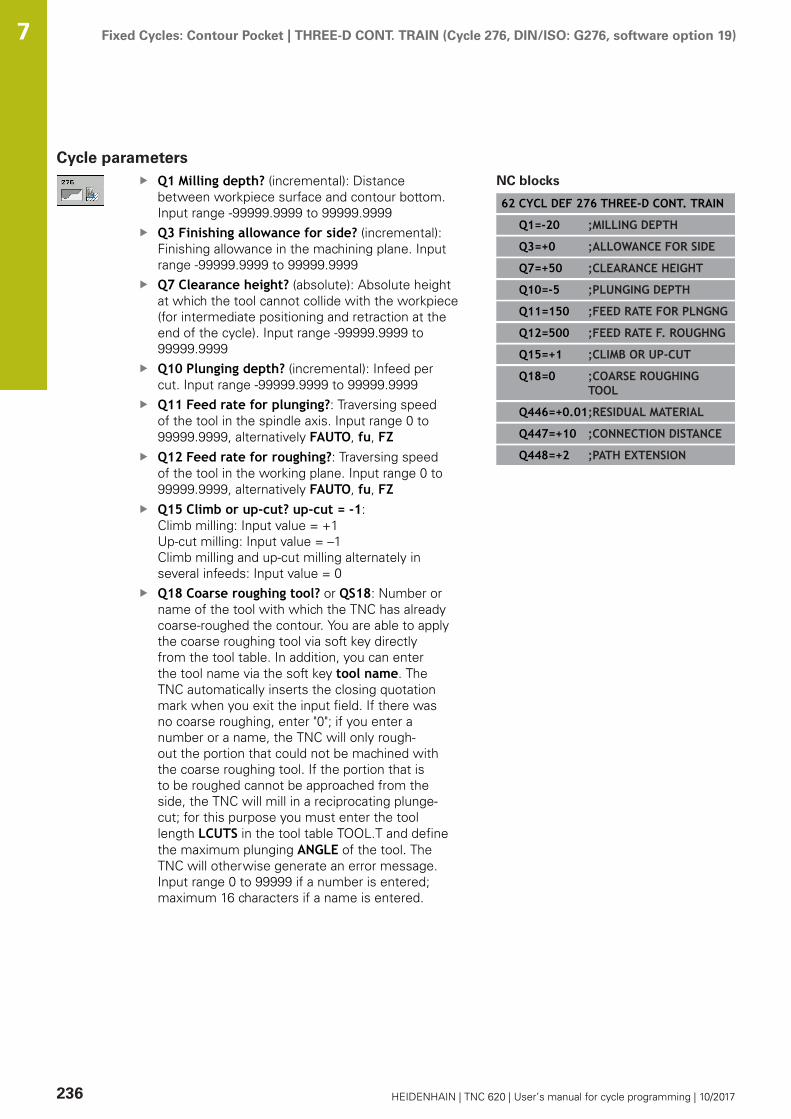
Fixed Cycles: Contour Pocket | THREE-D CONT. TRAIN (Cycle 276, DIN/ISO: G276, software option 19) 7
236 HEIDENHAIN | TNC 620 | User’s manual for cycle programming | 10/2017
Cycle parametersQ1 Milling depth? (incremental): Distancebetween workpiece surface and contour bottom.Input range -99999.9999 to 99999.9999Q3 Finishing allowance for side? (incremental):Finishing allowance in the machining plane. Inputrange -99999.9999 to 99999.9999Q7 Clearance height? (absolute): Absolute heightat which the tool cannot collide with the workpiece(for intermediate positioning and retraction at theend of the cycle). Input range -99999.9999 to99999.9999Q10 Plunging depth? (incremental): Infeed percut. Input range -99999.9999 to 99999.9999Q11 Feed rate for plunging?: Traversing speedof the tool in the spindle axis. Input range 0 to99999.9999, alternatively FAUTO, fu, FZQ12 Feed rate for roughing?: Traversing speedof the tool in the working plane. Input range 0 to99999.9999, alternatively FAUTO, fu, FZQ15 Climb or up-cut? up-cut = -1: Climb milling: Input value = +1 Up-cut milling: Input value = –1 Climb milling and up-cut milling alternately inseveral infeeds: Input value = 0Q18 Coarse roughing tool? or QS18: Number orname of the tool with which the TNC has alreadycoarse-roughed the contour. You are able to applythe coarse roughing tool via soft key directlyfrom the tool table. In addition, you can enterthe tool name via the soft key tool name. TheTNC automatically inserts the closing quotationmark when you exit the input field. If there wasno coarse roughing, enter "0"; if you enter anumber or a name, the TNC will only rough-out the portion that could not be machined withthe coarse roughing tool. If the portion that isto be roughed cannot be approached from theside, the TNC will mill in a reciprocating plunge-cut; for this purpose you must enter the toollength LCUTS in the tool table TOOL.T and definethe maximum plunging ANGLE of the tool. TheTNC will otherwise generate an error message.Input range 0 to 99999 if a number is entered;maximum 16 characters if a name is entered.
NC blocks
62 CYCL DEF 276 THREE-D CONT. TRAIN
Q1=-20 ;MILLING DEPTH
Q3=+0 ;ALLOWANCE FOR SIDE
Q7=+50 ;CLEARANCE HEIGHT
Q10=-5 ;PLUNGING DEPTH
Q11=150 ;FEED RATE FOR PLNGNG
Q12=500 ;FEED RATE F. ROUGHNG
Q15=+1 ;CLIMB OR UP-CUT
Q18=0 ;COARSE ROUGHINGTOOL
Q446=+0.01;RESIDUAL MATERIAL
Q447=+10 ;CONNECTION DISTANCE
Q448=+2 ;PATH EXTENSION

Fixed Cycles: Contour Pocket | THREE-D CONT. TRAIN (Cycle 276, DIN/ISO: G276, software option 19) 7
HEIDENHAIN | TNC 620 | User’s manual for cycle programming | 10/2017 237
Q446 Accepted residual material? Define towhich value in mm you accept residual material onyour contour. If you enter 0.01 mm for example,the TNC no longer performs machining of residualmaterial from a residual material thickness of 0.01mm. Input range 0.001 to 9.999Q447 Maximum connection distance? Maximumdistance between two areas to be fine roughed.Within this distance the TNC traverses without alifting movement along the contour at machiningdepth. Input range 0 to 999.999Q448 Path extension? Length by which thetool path is extended at the start and end of thecontour. The TNC always extends the tool pathparallel to the contour. Input range 0 to 99.999

Fixed Cycles: Contour Pocket | CONTOUR TRAIN DATA (Cycle 270, DIN/ISO: G270, software option 19) 7
238 HEIDENHAIN | TNC 620 | User’s manual for cycle programming | 10/2017
7.11 CONTOUR TRAIN DATA (Cycle 270, DIN/ISO: G270, software option 19)
Please note while programming:You can use this cycle to specify various properties of Cycle 25CONTOUR TRAIN.
Cycle 270 is DEF active, which means that it becomeseffective as soon as it is defined in the part program.If Cycle 270 is used, do not define any radiuscompensation in the contour subprogram.Define Cycle 270 before Cycle 25.
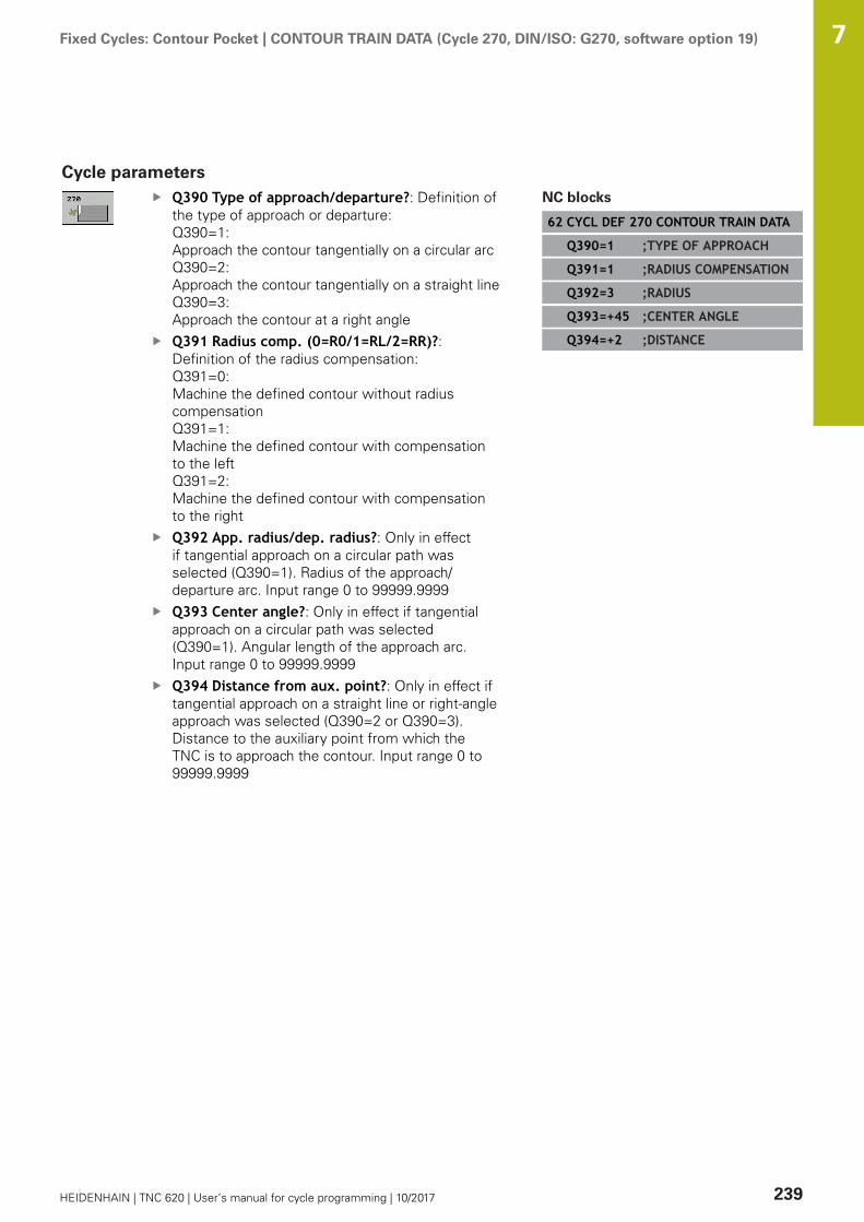
Fixed Cycles: Contour Pocket | CONTOUR TRAIN DATA (Cycle 270, DIN/ISO: G270, software option 19) 7
HEIDENHAIN | TNC 620 | User’s manual for cycle programming | 10/2017 239
Cycle parametersQ390 Type of approach/departure?: Definition ofthe type of approach or departure:Q390=1: Approach the contour tangentially on a circular arcQ390=2: Approach the contour tangentially on a straight lineQ390=3: Approach the contour at a right angleQ391 Radius comp. (0=R0/1=RL/2=RR)?:Definition of the radius compensation:Q391=0: Machine the defined contour without radiuscompensationQ391=1: Machine the defined contour with compensationto the leftQ391=2: Machine the defined contour with compensationto the rightQ392 App. radius/dep. radius?: Only in effectif tangential approach on a circular path wasselected (Q390=1). Radius of the approach/departure arc. Input range 0 to 99999.9999Q393 Center angle?: Only in effect if tangentialapproach on a circular path was selected(Q390=1). Angular length of the approach arc.Input range 0 to 99999.9999Q394 Distance from aux. point?: Only in effect iftangential approach on a straight line or right-angleapproach was selected (Q390=2 or Q390=3).Distance to the auxiliary point from which theTNC is to approach the contour. Input range 0 to99999.9999
NC blocks
62 CYCL DEF 270 CONTOUR TRAIN DATA
Q390=1 ;TYPE OF APPROACH
Q391=1 ;RADIUS COMPENSATION
Q392=3 ;RADIUS
Q393=+45 ;CENTER ANGLE
Q394=+2 ;DISTANCE

Fixed Cycles: Contour Pocket | TROCHOIDAL SLOT (Cycle 275, DIN/ISO: G275, software option 19) 7
240 HEIDENHAIN | TNC 620 | User’s manual for cycle programming | 10/2017
7.12 TROCHOIDAL SLOT (Cycle 275, DIN/ISO:G275, software option 19)
Cycle runIn conjunction with Cycle 14 CONTOUR, this cycle facilitates thecomplete machining of open and closed slots or contour slots usingtrochoidal milling.With trochoidal milling, large cutting depths and high cutting speedsare possible because the equally distributed cutting conditionsprevent wear-increasing influences on the tool. When tool inserts areused the entire cutting length is exploited to increase the attainablechip volume per tooth. Moreover, trochoidal milling is easy on themachine mechanics.Depending on the cycle parameters you select, the followingmachining alternatives are available:
Complete machining: Roughing, side finishingOnly roughingOnly side finishing
Roughing with closed slots
The contour description of a closed slot must always start with astraight-line block (L block).1 Following the positioning logic, the tool moves to the starting
point of the contour description and moves in a reciprocatingmotion at the plunging angle defined in the tool table to the firstinfeed depth. Specify the plunging strategy with parameter Q366.
2 The TNC roughs the slot in circular motions to the contour endpoint. During the circular motion the TNC moves the tool inmachining direction by an infeed you can define (Q436). Defineclimb or up-cut of the circular motion in parameter Q351.
3 At the contour end point, the TNC moves the tool to clearanceheight and returns to the starting point of the contour description.
4 This process is repeated until the programmed slot depth isreached.
Finishing with closed slots
5 Inasmuch as a finishing allowance is defined, the TNC finishesthe slot walls, in multiple infeeds if so specified. Starting fromthe defined starting point, the TNC approaches the slot walltangentially. Climb or up-cut are taken into consideration.
Program structure: Machining withSL cycles
0 BEGIN PGM CYC275 MM
...
12 CYCL DEF 14.0 CONTOUR
13 CYCL DEF 14.1 CONTOUR LABEL 10
14 CYCL DEF 275 TROCHOIDAL SLOT...
15 CYCL CALL M3
...
50 L Z+250 R0 FMAX M2
51 LBL 10
...
55 LBL 0
...
99 END PGM CYC275 MM
Fixed Cycles: Contour Pocket | TROCHOIDAL SLOT (Cycle 275, DIN/ISO: G275, software option 19) 7
HEIDENHAIN | TNC 620 | User’s manual for cycle programming | 10/2017 241
Roughing with open slots
The contour description of an open slot must always start with anapproach block (APPR).1 Following the positioning logic, the tool moves to the starting
point of the machining operation as defined by the parametersin the APPR block and positions there perpendicular to the firstplunging depth.
2 The TNC roughs the slot in circular motions to the contour endpoint. During the circular motion the TNC moves the tool inmachining direction by an infeed you can define (Q436). Defineclimb or up-cut of the circular motion in parameter Q351.
3 At the contour end point, the TNC moves the tool to clearanceheight and returns to the starting point of the contour description.
4 This process is repeated until the programmed slot depth isreached.
Finishing with open slots
5 Inasmuch as a finishing allowance is defined, the TNC finishesthe slot walls, in multiple infeeds if so specified. Starting from thedefined starting point of the APPR block, the TNC approaches theslot wall. Climb or up-cut are taken into consideration.
Fixed Cycles: Contour Pocket | TROCHOIDAL SLOT (Cycle 275, DIN/ISO: G275, software option 19) 7
242 HEIDENHAIN | TNC 620 | User’s manual for cycle programming | 10/2017
Please note while programming:
The algebraic sign for the cycle parameter DEPTHdetermines the working direction. If you programDEPTH=0, the cycle will not be executed.When using Cycle 275 TROCHOIDAL SLOT, youcan define only one contour subprogram in Cycle 14CONTOUR.Define the center line of the slot with all available pathfunctions in the contour subprogram.The memory capacity for programming an SL cycle islimited. You can program up to 16384 contour elementsin one SL cycle.The TNC does not need Cycle 20 CONTOUR DATA inconjunction with Cycle 275.The starting point of a closed slot must not be located ina contour corner.
NOTICEDanger of collision!
If you set the parameter posAfterContPocket toToolAxClearanceHeight, the TNC positions the tool after the endof the cycle only in the tool axis direction to the clearance height.The TNC does not position the tool in the working plane.
After the end of the cycle, position the tool with allcoordinates of the working plane, e.g. L X+80 Y+0 R0 FMAX
After the cycle, program the absolute position (not anincremental traversing movement)

Fixed Cycles: Contour Pocket | TROCHOIDAL SLOT (Cycle 275, DIN/ISO: G275, software option 19) 7
HEIDENHAIN | TNC 620 | User’s manual for cycle programming | 10/2017 243
Cycle parametersQ215 Machining operation (0/1/2)?: Definemachining operation:0: Roughing and finishing1: Only roughing2: Only finishing Side finishing and floor finishing are only machinedwhen the specific allowance (Q368, Q369) isdefinedQ219 Width of slot? (value parallel to thesecondary axis of the working plane): Enter theslot width. If you enter a slot width that equals thetool diameter, the TNC will carry out the roughingprocess only (slot milling). Maximum slot width forroughing: Twice the tool diameter. Input range 0 to99999.9999Q368 Finishing allowance for side? (incremental):Finishing allowance in the machining plane. Inputrange 0 to 99999.9999Q436 Feed per revolution? (absolute): Value bywhich the TNC moves the tool in the machiningdirection per revolution. Input range 0 to99999.9999Q207 Feed rate for milling?: Traversing speed ofthe tool in mm/min while milling. Input range 0 to99999.999 alternatively FAUTO, fu, FZQ12 Feed rate for roughing?: Traversing speedof the tool in the working plane. Input range 0 to99999.9999, alternatively FAUTO, fu, FZQ351 Direction? Climb=+1, Up-cut=-1: Type ofmilling operation with M3:+1 = Climb–1 = Up-cutPREDEF: The TNC uses the value from theGLOBAL DEF block (if you enter 0, climb milling isperformed)Q201 Depth? (incremental): Distance betweenworkpiece surface and bottom of slot. Input range-99999.9999 to 99999.9999
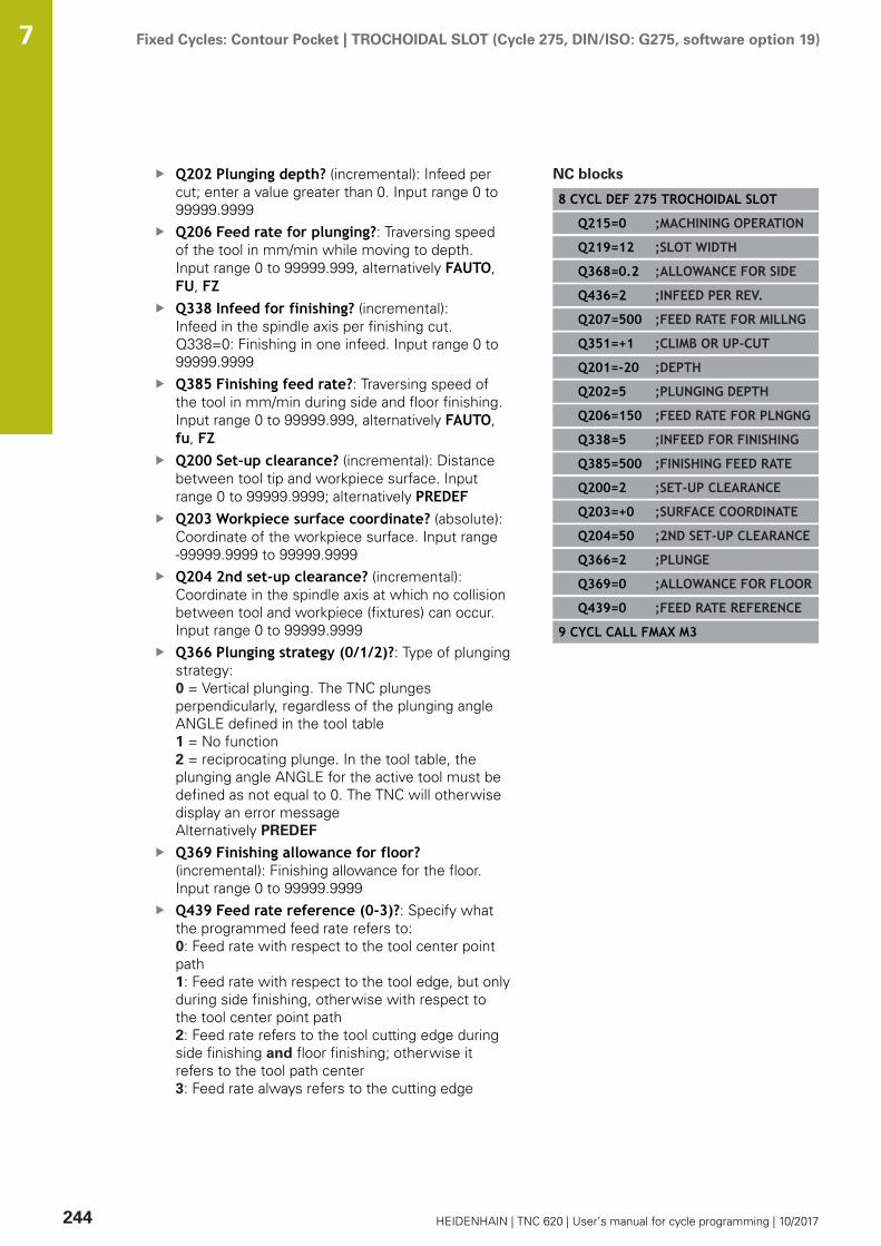
Fixed Cycles: Contour Pocket | TROCHOIDAL SLOT (Cycle 275, DIN/ISO: G275, software option 19) 7
244 HEIDENHAIN | TNC 620 | User’s manual for cycle programming | 10/2017
Q202 Plunging depth? (incremental): Infeed percut; enter a value greater than 0. Input range 0 to99999.9999Q206 Feed rate for plunging?: Traversing speedof the tool in mm/min while moving to depth.Input range 0 to 99999.999, alternatively FAUTO,FU, FZQ338 Infeed for finishing? (incremental):Infeed in the spindle axis per finishing cut.Q338=0: Finishing in one infeed. Input range 0 to99999.9999Q385 Finishing feed rate?: Traversing speed ofthe tool in mm/min during side and floor finishing.Input range 0 to 99999.999, alternatively FAUTO,fu, FZQ200 Set-up clearance? (incremental): Distancebetween tool tip and workpiece surface. Inputrange 0 to 99999.9999; alternatively PREDEFQ203 Workpiece surface coordinate? (absolute):Coordinate of the workpiece surface. Input range-99999.9999 to 99999.9999Q204 2nd set-up clearance? (incremental):Coordinate in the spindle axis at which no collisionbetween tool and workpiece (fixtures) can occur.Input range 0 to 99999.9999Q366 Plunging strategy (0/1/2)?: Type of plungingstrategy:0 = Vertical plunging. The TNC plungesperpendicularly, regardless of the plunging angleANGLE defined in the tool table1 = No function2 = reciprocating plunge. In the tool table, theplunging angle ANGLE for the active tool must bedefined as not equal to 0. The TNC will otherwisedisplay an error messageAlternatively PREDEF
Q369 Finishing allowance for floor?(incremental): Finishing allowance for the floor.Input range 0 to 99999.9999Q439 Feed rate reference (0-3)?: Specify whatthe programmed feed rate refers to:0: Feed rate with respect to the tool center pointpath1: Feed rate with respect to the tool edge, but onlyduring side finishing, otherwise with respect tothe tool center point path2: Feed rate refers to the tool cutting edge duringside finishing and floor finishing; otherwise itrefers to the tool path center3: Feed rate always refers to the cutting edge
NC blocks
8 CYCL DEF 275 TROCHOIDAL SLOT
Q215=0 ;MACHINING OPERATION
Q219=12 ;SLOT WIDTH
Q368=0.2 ;ALLOWANCE FOR SIDE
Q436=2 ;INFEED PER REV.
Q207=500 ;FEED RATE FOR MILLNG
Q351=+1 ;CLIMB OR UP-CUT
Q201=-20 ;DEPTH
Q202=5 ;PLUNGING DEPTH
Q206=150 ;FEED RATE FOR PLNGNG
Q338=5 ;INFEED FOR FINISHING
Q385=500 ;FINISHING FEED RATE
Q200=2 ;SET-UP CLEARANCE
Q203=+0 ;SURFACE COORDINATE
Q204=50 ;2ND SET-UP CLEARANCE
Q366=2 ;PLUNGE
Q369=0 ;ALLOWANCE FOR FLOOR
Q439=0 ;FEED RATE REFERENCE
9 CYCL CALL FMAX M3

Fixed Cycles: Contour Pocket | Programming Examples 7
HEIDENHAIN | TNC 620 | User’s manual for cycle programming | 10/2017 245
7.13 Programming Examples
Example: Roughing-out and fine-roughing a pocket
0 BEGIN PGM C20 MM
1 BLK FORM 0.1 Z X-10 Y-10 Z-40
2 BLK FORM 0.2 X+100 Y+100 Z+0 Definition of workpiece blank
3 TOOL CALL 1 Z S2500 Tool call: coarse roughing tool, diameter 30
4 L Z+250 R0 FMAX Retract the tool
5 CYCL DEF 14.0 CONTOUR Define contour subprogram
6 CYCL DEF 14.1 CONTOUR LABEL 1
7 CYCL DEF 20 CONTOUR DATA Define general machining parameters
Q1=-20 ;MILLING DEPTH
Q2=1 ;TOOL PATH OVERLAP
Q3=+0 ;ALLOWANCE FOR SIDE
Q4=+0 ;ALLOWANCE FOR FLOOR
Q5=+0 ;SURFACE COORDINATE
Q6=2 ;SET-UP CLEARANCE
Q7=+100 ;CLEARANCE HEIGHT
Q8=0.1 ;ROUNDING RADIUS
Q9=-1 ;ROTATIONAL DIRECTION
8 CYCL DEF 22 ROUGH-OUT Cycle definition: Coarse roughing
Q10=5 ;PLUNGING DEPTH
Q11=100 ;FEED RATE FOR PLNGNG
Q12=350 ;FEED RATE F. ROUGHNG
Q18=0 ;COARSE ROUGHING TOOL
Q19=150 ;FEED RATE FOR RECIP.
Q208=30000 ;RETRACTION FEED RATE
9 CYCL CALL M3 Cycle call: Coarse roughing
10 L Z+250 R0 FMAX M6 Tool change

Fixed Cycles: Contour Pocket | Programming Examples 7
246 HEIDENHAIN | TNC 620 | User’s manual for cycle programming | 10/2017
11 TOOL CALL 2 Z S3000 Tool call: fine roughing tool, diameter 15
12 CYCL DEF 22 ROUGH-OUT Define the fine roughing cycle
Q10=5 ;PLUNGING DEPTH
Q11=100 ;FEED RATE FOR PLNGNG
Q12=350 ;FEED RATE F. ROUGHNG
Q18=1 ;COARSE ROUGHING TOOL
Q19=150 ;FEED RATE FOR RECIP.
Q208=30000 ;RETRACTION FEED RATE
13 CYCL CALL M3 Cycle call: Fine roughing
14 L Z+250 R0 FMAX M2 Retract in the tool axis, end program
15 LBL 1 Contour subprogram
16 L X+0 Y+30 RR
17 FC DR- R30 CCX+30 CCY+30
18 FL AN+60 PDX+30 PDY+30 D10
19 FSELECT 3
20 FPOL X+30 Y+30
21 FC DR- R20 CCPR+55 CCPA+60
22 FSELECT 2
23 FL AN-120 PDX+30 PDY+30 D10
24 FSELECT 3
25 FC X+0 DR- R30 CCX+30 CCY+30
26 FSELECT 2
27 LBL 0
28 END PGM C20 MM

Fixed Cycles: Contour Pocket | Programming Examples 7
HEIDENHAIN | TNC 620 | User’s manual for cycle programming | 10/2017 247
Example: Pilot drilling, roughing-out and finishingoverlapping contours
0 BEGIN PGM C21 MM
1 BLK FORM 0.1 Z X+0 Y+0 Z-40 Definition of workpiece blank
2 BLK FORM 0.2 X+100 Y+100 Z+0
3 TOOL CALL 1 Z S2500 Tool call: Drill, diameter 12
4 L Z+250 R0 FMAX Retract the tool
5 CYCL DEF 14.0 CONTOUR Define contour subprogram
6 CYCL DEF 14.1 CONTOUR LABEL 1/2/3/4
7 CYCL DEF 20 CONTOUR DATA Define general machining parameters
Q1=-20 ;MILLING DEPTH
Q2=1 ;TOOL PATH OVERLAP
Q3=+0.5 ;ALLOWANCE FOR SIDE
Q4=+0.5 ;ALLOWANCE FOR FLOOR
Q5=+0 ;SURFACE COORDINATE
Q6=2 ;SET-UP CLEARANCE
Q7=+100 ;CLEARANCE HEIGHT
Q8=0.1 ;ROUNDING RADIUS
Q9=-1 ;ROTATIONAL DIRECTION
8 CYCL DEF 21 PILOT DRILLING Cycle definition: Pilot drilling
Q10=5 ;PLUNGING DEPTH
Q11=250 ;FEED RATE FOR PLNGNG
Q13=2 ;ROUGH-OUT TOOL
9 CYCL CALL M3 Cycle call: Pilot drilling
10 L +250 R0 FMAX M6 Tool change
11 TOOL CALL 2 Z S3000 Call the tool for roughing/finishing, diameter 12
12 CYCL DEF 22 ROUGH-OUT Cycle definition: Rough-out
Q10=5 ;PLUNGING DEPTH
Q11=100 ;FEED RATE FOR PLNGNG

Fixed Cycles: Contour Pocket | Programming Examples 7
248 HEIDENHAIN | TNC 620 | User’s manual for cycle programming | 10/2017
Q12=350 ;FEED RATE F. ROUGHNG
Q18=0 ;COARSE ROUGHING TOOL
Q19=150 ;FEED RATE FOR RECIP.
Q208=30000 ;RETRACTION FEED RATE
13 CYCL CALL M3 Cycle call: Rough-out
14 CYCL DEF 23 FLOOR FINISHING Cycle definition: Floor finishing
Q11=100 ;FEED RATE FOR PLNGNG
Q12=200 ;FEED RATE F. ROUGHNG
Q208=30000 ;RETRACTION FEED RATE
15 CYCL CALL Cycle call: Floor finishing
16 CYCL DEF 24 SIDE FINISHING Cycle definition: Side finishing
Q9=+1 ;ROTATIONAL DIRECTION
Q10=5 ;PLUNGING DEPTH
Q11=100 ;FEED RATE FOR PLNGNG
Q12=400 ;FEED RATE F. ROUGHNG
Q14=+0 ;ALLOWANCE FOR SIDE
17 CYCL CALL Cycle call: Side finishing
18 L Z+250 R0 FMAX M2 Retract the tool, end program
19 LBL 1 Contour subprogram 1: left pocket
20 CC X+35 Y+50
21 L X+10 Y+50 RR
22 C X+10 DR-
23 LBL 0
24 LBL 2 Contour subprogram 2: right pocket
25 CC X+65 Y+50
26 L X+90 Y+50 RR
27 C X+90 DR-
28 LBL 0
29 LBL 3 Contour subprogram 3: square left island
30 L X+27 Y+50 RL
31 L Y+58
32 L X+43
33 L Y+42
34 L X+27
35 LBL 0
36 LBL 4 Contour subprogram 4: triangular right island
37 L X+65 Y+42 RL
38 L X+57
39 L X+65 Y+58
40 L X+73 Y+42
41 LBL 0
42 END PGM C21 MM

Fixed Cycles: Contour Pocket | Programming Examples 7
HEIDENHAIN | TNC 620 | User’s manual for cycle programming | 10/2017 249
Example: Contour train
0 BEGIN PGM C25 MM
1 BLK FORM 0.1 Z X+0 Y+0 Z-40 Definition of workpiece blank
2 BLK FORM 0.2 X+100 Y+100 Z+0
3 TOOL CALL 1 Z S2000 Tool call: Diameter 20
4 L Z+250 R0 FMAX Retract the tool
5 CYCL DEF 14.0 CONTOUR Define contour subprogram
6 CYCL DEF 14.1 CONTOUR LABEL 1
7 CYCL DEF 25 CONTOUR TRAIN Define machining parameters
Q1=-20 ;MILLING DEPTH
Q3=+0 ;ALLOWANCE FOR SIDE
Q5=+0 ;SURFACE COORDINATE
Q7=+250 ;CLEARANCE HEIGHT
Q10=5 ;PLUNGING DEPTH
Q11=100 ;FEED RATE FOR PLNGNG
Q12=200 ;FEED RATE FOR MILLNG
Q15=+1 ;CLIMB OR UP-CUT
8 CYCL CALL M3 Cycle call
9 L Z+250 R0 FMAX M2 Retract the tool, end program
10 LBL 1 Contour subprogram
11 L X+0 Y+15 RL
12 L X+5 Y+20
13 CT X+5 Y+75
14 L Y+95
15 RND R7.5
16 L X+50
17 RND R7.5
18 L X+100 Y+80
19 LBL 0
20 END PGM C25 MM


8Fixed Cycles:
Cylindrical Surface

Fixed Cycles: Cylindrical Surface | Fundamentals 8
252 HEIDENHAIN | TNC 620 | User’s manual for cycle programming | 10/2017
8.1 Fundamentals
Overview of cylindrical surface cycles
Soft key Cycle Page
27 CYLINDER SURFACE 253
28 CYLINDER SURFACE Slot milling
256
29 CYLINDER SURFACE Ridge milling
260
39 CYLINDER SURFACE Contour
263
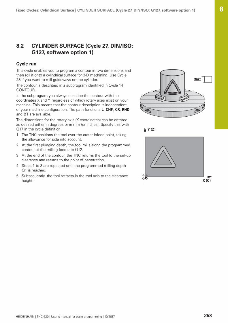
Fixed Cycles: Cylindrical Surface | CYLINDER SURFACE (Cycle 27, DIN/ISO: G127, software option 1) 8
HEIDENHAIN | TNC 620 | User’s manual for cycle programming | 10/2017 253
8.2 CYLINDER SURFACE (Cycle 27, DIN/ISO:G127, software option 1)
Cycle runThis cycle enables you to program a contour in two dimensions andthen roll it onto a cylindrical surface for 3-D machining. Use Cycle28 if you want to mill guideways on the cylinder.The contour is described in a subprogram identified in Cycle 14CONTOUR.In the subprogram you always describe the contour with thecoordinates X and Y, regardless of which rotary axes exist on yourmachine. This means that the contour description is independentof your machine configuration. The path functions L, CHF, CR, RNDand CT are available.The dimensions for the rotary axis (X coordinates) can be enteredas desired either in degrees or in mm (or inches). Specify this withQ17 in the cycle definition.1 The TNC positions the tool over the cutter infeed point, taking
the allowance for side into account.2 At the first plunging depth, the tool mills along the programmed
contour at the milling feed rate Q12.3 At the end of the contour, the TNC returns the tool to the set-up
clearance and returns to the point of penetration.4 Steps 1 to 3 are repeated until the programmed milling depth
Q1 is reached.5 Subsequently, the tool retracts in the tool axis to the clearance
height.
Y (Z)
X (C)
Fixed Cycles: Cylindrical Surface | CYLINDER SURFACE (Cycle 27, DIN/ISO: G127, software option 1) 8
254 HEIDENHAIN | TNC 620 | User’s manual for cycle programming | 10/2017
Please note while programming:
Refer to your machine manual.The machine and TNC must be prepared for cylindersurface interpolation by the machine tool builder.
In the first NC block of the contour program, alwaysprogram both cylinder surface coordinates.The memory capacity for programming an SL cycle islimited. You can program up to 16384 contour elementsin one SL cycle.The algebraic sign for the cycle parameter DEPTHdetermines the working direction. If you programDEPTH=0, the cycle will not be executed.This cycle requires a center-cut end mill (ISO 1641).The cylinder must be set up centered on the rotarytable. Set the preset to the center of the rotary table.The spindle axis must be perpendicular to the rotarytable axis when the cycle is called. If this is notthe case, the TNC will generate an error message.Switching of the kinematics may be required.This cycle can also be used in a tilted working plane.The set-up clearance must be greater than the toolradius.The machining time can increase if the contour consistsof many non-tangential contour elements.When you use local QL Q parameters in a contoursubprogram you must also assign or calculate these inthe contour subprogram.

Fixed Cycles: Cylindrical Surface | CYLINDER SURFACE (Cycle 27, DIN/ISO: G127, software option 1) 8
HEIDENHAIN | TNC 620 | User’s manual for cycle programming | 10/2017 255
Cycle parametersQ1 Milling depth? (incremental): Distancebetween cylindrical surface and contour bottom.Input range -99999.9999 to 99999.9999Q3 Finishing allowance for side? (incremental):Finishing allowance in the plane of the unrolledcylindrical surface. This allowance is effective inthe direction of the radius compensation. Inputrange -99999.9999 to 99999.9999Q6 Set-up clearance? (incremental): Distancebetween tool tip and cylindrical surface. Inputrange 0 to 99999.9999Q10 Plunging depth? (incremental): Infeed percut. Input range -99999.9999 to 99999.9999Q11 Feed rate for plunging?: Traversing speedof the tool in the spindle axis. Input range 0 to99999.9999, alternatively FAUTO, fu, FZQ12 Feed rate for roughing?: Traversing speedof the tool in the working plane. Input range 0 to99999.9999, alternatively FAUTO, fu, FZQ16 Cylinder radius?: Radius of the cylinder onwhich the contour is to be machined. Input range 0to 99999.9999Q17 Dimension type? deg=0 MM/INCH=1: Thedimensions for the rotary axis of the subprogramare given either in degrees or in mm/inches
NC blocks
63 CYCL DEF 27 CYLINDER SURFACE
Q1=-8 ;MILLING DEPTH
Q3=+0 ;ALLOWANCE FOR SIDE
Q6=+0 ;SET-UP CLEARANCE
Q10=+3 ;PLUNGING DEPTH
Q11=100 ;FEED RATE FOR PLNGNG
Q12=350 ;FEED RATE F. ROUGHNG
Q16=25 ;RADIUS
Q17=0 ;TYPE OF DIMENSION

Fixed Cycles: Cylindrical Surface | CYLINDER SURFACE Slot milling (Cycle 28, DIN/ISO: G128, softwareoption 1)
8
256 HEIDENHAIN | TNC 620 | User’s manual for cycle programming | 10/2017
8.3 CYLINDER SURFACE Slot milling (Cycle28, DIN/ISO: G128, software option 1)
Cycle runWith this cycle you can program a guide notch in two dimensionsand then transfer it onto a cylindrical surface. Unlike Cycle 27,with this cycle the TNC adjusts the tool so that, with radiuscompensation active, the walls of the slot are nearly parallel. Youcan machine exactly parallel walls by using a tool that is exactly aswide as the slot.The smaller the tool is with respect to the slot width, the larger thedistortion in circular arcs and oblique line segments. To minimizethis process-related distortion, you can define the parameterQ21. This parameter specifies the tolerance with which the TNCmachines a slot as similar as possible to a slot machined with a toolof the same width as the slot.Program the midpoint path of the contour together with the toolradius compensation. With the radius compensation you specifywhether the TNC cuts the slot with climb milling or up-cut milling.1 The TNC positions the tool over the cutter infeed point.2 The TNC moves the tool to the first plunging depth. The
tool approaches the workpiece on a tangential path or on astraight line at the milling feed rate Q12. The approachingbehavior depends on the parameter ConfigDatum CfgGeoCycleapprDepCylWall.
3 At the first plunging depth, the tool mills along the programmedslot wall at the milling feed rate Q12 while respecting thefinishing allowance for the side.
4 At the end of the contour, the TNC moves the tool to theopposite wall and returns to the infeed point.
5 Steps 2 to 3 are repeated until the programmed milling depthQ1 is reached.
6 If you have defined the tolerance in Q21, the TNC thenremachines the slot walls to be as parallel as possible.
7 Finally, the tool retracts in the tool axis to the clearance height.
Y (Z)
X (C)
Fixed Cycles: Cylindrical Surface | CYLINDER SURFACE Slot milling (Cycle 28, DIN/ISO: G128, softwareoption 1)
8
HEIDENHAIN | TNC 620 | User’s manual for cycle programming | 10/2017 257
Please note while programming:
This cycle performs an inclined 5-axis machiningoperation. To run this cycle, the first machine axis belowthe machine table must be a rotary axis. In addition, itmust be possible to position the tool perpendicular tothe cylinder surface.
Define the approaching behavior in ConfigDatum,CfgGeoCycle, apprDepCylWall
CircleTangential: Tangential approach and departureLineNormal: The movement to the contour startingpoint is not performed on a tangential path, but on astraight line
In the first NC block of the contour program, alwaysprogram both cylinder surface coordinates.The algebraic sign for the cycle parameter DEPTHdetermines the working direction. If you programDEPTH=0, the cycle will not be executed.This cycle requires a center-cut end mill (ISO 1641).The cylinder must be set up centered on the rotarytable. Set the preset to the center of the rotary table.The spindle axis must be perpendicular to the rotarytable axis when the cycle is called.This cycle can also be used in a tilted working plane.The set-up clearance must be greater than the toolradius.The machining time can increase if the contour consistsof many non-tangential contour elements.When you use local QL Q parameters in a contoursubprogram you must also assign or calculate these inthe contour subprogram.
Fixed Cycles: Cylindrical Surface | CYLINDER SURFACE Slot milling (Cycle 28, DIN/ISO: G128, softwareoption 1)
8
258 HEIDENHAIN | TNC 620 | User’s manual for cycle programming | 10/2017
NOTICEDanger of collision!
If the spindle is not switched on when the cycle is called acollision may occur.
Define whether the TNC issues an error messageif the spindle is not switched on via the parameterdisplaySpindleErr, on/off.The function needs to be adapted by your machinemanufacturer.
NOTICEDanger of collision!
At the end, the TNC positions the tool back to the set-up clearance, or to the 2nd set-up clearance if one wasprogrammed. The end position of the tool after the cycle mustnot match the starting position.
Control the traversing movements of the machineIn the simulation, control the end position of the tool after thecycleAfter the cycle, program the absolute (not incremental)coordinates
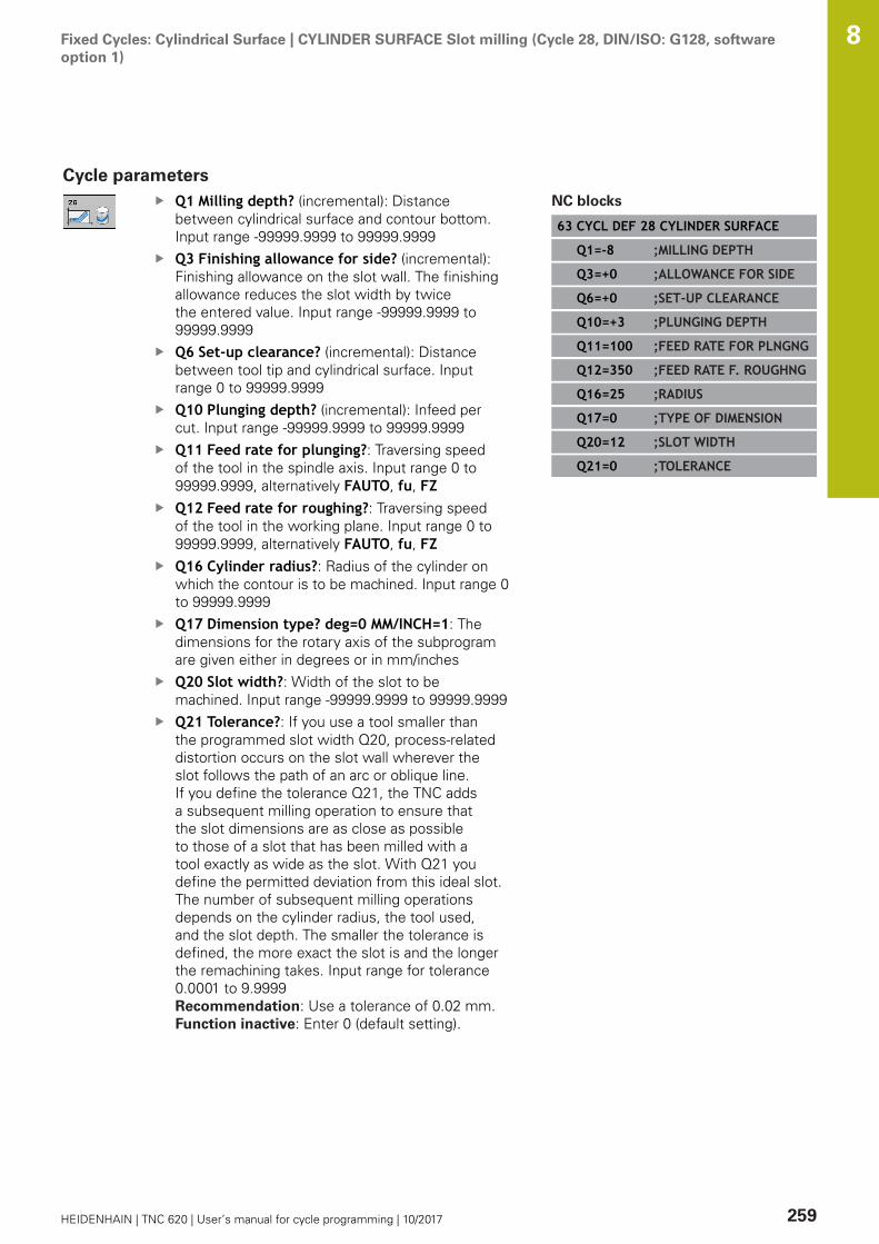
Fixed Cycles: Cylindrical Surface | CYLINDER SURFACE Slot milling (Cycle 28, DIN/ISO: G128, softwareoption 1)
8
HEIDENHAIN | TNC 620 | User’s manual for cycle programming | 10/2017 259
Cycle parametersQ1 Milling depth? (incremental): Distancebetween cylindrical surface and contour bottom.Input range -99999.9999 to 99999.9999Q3 Finishing allowance for side? (incremental):Finishing allowance on the slot wall. The finishingallowance reduces the slot width by twicethe entered value. Input range -99999.9999 to99999.9999Q6 Set-up clearance? (incremental): Distancebetween tool tip and cylindrical surface. Inputrange 0 to 99999.9999Q10 Plunging depth? (incremental): Infeed percut. Input range -99999.9999 to 99999.9999Q11 Feed rate for plunging?: Traversing speedof the tool in the spindle axis. Input range 0 to99999.9999, alternatively FAUTO, fu, FZQ12 Feed rate for roughing?: Traversing speedof the tool in the working plane. Input range 0 to99999.9999, alternatively FAUTO, fu, FZQ16 Cylinder radius?: Radius of the cylinder onwhich the contour is to be machined. Input range 0to 99999.9999Q17 Dimension type? deg=0 MM/INCH=1: Thedimensions for the rotary axis of the subprogramare given either in degrees or in mm/inchesQ20 Slot width?: Width of the slot to bemachined. Input range -99999.9999 to 99999.9999Q21 Tolerance?: If you use a tool smaller thanthe programmed slot width Q20, process-relateddistortion occurs on the slot wall wherever theslot follows the path of an arc or oblique line.If you define the tolerance Q21, the TNC addsa subsequent milling operation to ensure thatthe slot dimensions are as close as possibleto those of a slot that has been milled with atool exactly as wide as the slot. With Q21 youdefine the permitted deviation from this ideal slot.The number of subsequent milling operationsdepends on the cylinder radius, the tool used,and the slot depth. The smaller the tolerance isdefined, the more exact the slot is and the longerthe remachining takes. Input range for tolerance0.0001 to 9.9999Recommendation: Use a tolerance of 0.02 mm. Function inactive: Enter 0 (default setting).
NC blocks
63 CYCL DEF 28 CYLINDER SURFACE
Q1=-8 ;MILLING DEPTH
Q3=+0 ;ALLOWANCE FOR SIDE
Q6=+0 ;SET-UP CLEARANCE
Q10=+3 ;PLUNGING DEPTH
Q11=100 ;FEED RATE FOR PLNGNG
Q12=350 ;FEED RATE F. ROUGHNG
Q16=25 ;RADIUS
Q17=0 ;TYPE OF DIMENSION
Q20=12 ;SLOT WIDTH
Q21=0 ;TOLERANCE

Fixed Cycles: Cylindrical Surface | CYLINDER SURFACE Ridge milling (Cycle 29, DIN/ISO: G129, softwareoption 1)
8
260 HEIDENHAIN | TNC 620 | User’s manual for cycle programming | 10/2017
8.4 CYLINDER SURFACE Ridge milling(Cycle 29, DIN/ISO: G129, softwareoption 1)
Cycle runThis cycle enables you to program a ridge in two dimensions andthen transfer it onto a cylindrical surface. With this cycle the TNCadjusts the tool so that, with radius compensation active, the wallsof the slot are always parallel. Program the midpoint path of theridge together with the tool radius compensation. With the radiuscompensation you specify whether the TNC cuts the ridge withclimb milling or up-cut milling.At the ends of the ridge the TNC always adds a semicircle whoseradius is half the ridge width.1 The TNC positions the tool over the starting point of machining.
The TNC calculates the starting point from the ridge width andthe tool diameter. It is located next to the first point defined inthe contour subprogram, offset by half the ridge width and thetool diameter. The radius compensation determines whethermachining begins from the left (1, RL = climb milling) or theright of the ridge (2, RR = up-cut milling).
2 After the TNC has positioned to the first plunging depth, the toolmoves on a circular arc at the milling feed rate Q12 tangentiallyto the ridge wall. If so programmed, it will leave metal for thefinishing allowance.
3 At the first plunging depth, the tool mills along the programmedridge wall at the milling feed rate Q12 until the stud iscompleted.
4 The tool then departs the ridge wall on a tangential path andreturns to the starting point of machining.
5 Steps 2 to 4 are repeated until the programmed milling depthQ1 is reached.
6 Finally, the tool retracts in the tool axis to the clearance height.
Y (Z)
X (C)

Fixed Cycles: Cylindrical Surface | CYLINDER SURFACE Ridge milling (Cycle 29, DIN/ISO: G129, softwareoption 1)
8
HEIDENHAIN | TNC 620 | User’s manual for cycle programming | 10/2017 261
Please note while programming:
This cycle performs an inclined 5-axis machiningoperation. To run this cycle, the first machine axis belowthe machine table must be a rotary axis. In addition, itmust be possible to position the tool perpendicular tothe cylinder surface.
In the first NC block of the contour program, alwaysprogram both cylinder surface coordinates.The algebraic sign for the cycle parameter DEPTHdetermines the working direction. If you programDEPTH=0, the cycle will not be executed.This cycle requires a center-cut end mill (ISO 1641).The cylinder must be set up centered on the rotarytable. Set the preset to the center of the rotary table.The spindle axis must be perpendicular to the rotarytable axis when the cycle is called. If this is notthe case, the TNC will generate an error message.Switching of the kinematics may be required.The set-up clearance must be greater than the toolradius.When you use local QL Q parameters in a contoursubprogram you must also assign or calculate these inthe contour subprogram.In the parameter CfgGeoCycle, displaySpindleErr, on/off, define whether the TNC should output an errormessage (on) or not (off) if spindle rotation is not activewhen the cycle is called. The function needs to beadapted by your machine manufacturer.

Fixed Cycles: Cylindrical Surface | CYLINDER SURFACE Ridge milling (Cycle 29, DIN/ISO: G129, softwareoption 1)
8
262 HEIDENHAIN | TNC 620 | User’s manual for cycle programming | 10/2017
Cycle parametersQ1 Milling depth? (incremental): Distancebetween cylindrical surface and contour bottom.Input range -99999.9999 to 99999.9999Q3 Finishing allowance for side? (incremental):Finishing allowance on the ridge wall. The finishingallowance increases the ridge width by twicethe entered value. Input range -99999.9999 to99999.9999Q6 Set-up clearance? (incremental): Distancebetween tool tip and cylindrical surface. Inputrange 0 to 99999.9999Q10 Plunging depth? (incremental): Infeed percut. Input range -99999.9999 to 99999.9999Q11 Feed rate for plunging?: Traversing speedof the tool in the spindle axis. Input range 0 to99999.9999, alternatively FAUTO, fu, FZQ12 Feed rate for roughing?: Traversing speedof the tool in the working plane. Input range 0 to99999.9999, alternatively FAUTO, fu, FZQ16 Cylinder radius?: Radius of the cylinder onwhich the contour is to be machined. Input range 0to 99999.9999Q17 Dimension type? deg=0 MM/INCH=1: Thedimensions for the rotary axis of the subprogramare given either in degrees or in mm/inchesQ20 Ridge width?: Width of the ridge to bemachined. Input range -99999.9999 to 99999.9999
NC blocks
63 CYCL DEF 29 CYL SURFACE RIDGE
Q1=-8 ;MILLING DEPTH
Q3=+0 ;ALLOWANCE FOR SIDE
Q6=+0 ;SET-UP CLEARANCE
Q10=+3 ;PLUNGING DEPTH
Q11=100 ;FEED RATE FOR PLNGNG
Q12=350 ;FEED RATE F. ROUGHNG
Q16=25 ;RADIUS
Q17=0 ;TYPE OF DIMENSION
Q20=12 ;RIDGE WIDTH
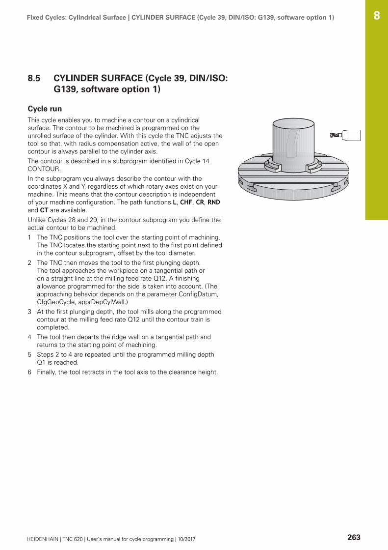
Fixed Cycles: Cylindrical Surface | CYLINDER SURFACE (Cycle 39, DIN/ISO: G139, software option 1) 8
HEIDENHAIN | TNC 620 | User’s manual for cycle programming | 10/2017 263
8.5 CYLINDER SURFACE (Cycle 39, DIN/ISO:G139, software option 1)
Cycle runThis cycle enables you to machine a contour on a cylindricalsurface. The contour to be machined is programmed on theunrolled surface of the cylinder. With this cycle the TNC adjusts thetool so that, with radius compensation active, the wall of the opencontour is always parallel to the cylinder axis.The contour is described in a subprogram identified in Cycle 14CONTOUR.In the subprogram you always describe the contour with thecoordinates X and Y, regardless of which rotary axes exist on yourmachine. This means that the contour description is independentof your machine configuration. The path functions L, CHF, CR, RNDand CT are available.Unlike Cycles 28 and 29, in the contour subprogram you define theactual contour to be machined.1 The TNC positions the tool over the starting point of machining.
The TNC locates the starting point next to the first point definedin the contour subprogram, offset by the tool diameter.
2 The TNC then moves the tool to the first plunging depth.The tool approaches the workpiece on a tangential path oron a straight line at the milling feed rate Q12. A finishingallowance programmed for the side is taken into account. (Theapproaching behavior depends on the parameter ConfigDatum,CfgGeoCycle, apprDepCylWall.)
3 At the first plunging depth, the tool mills along the programmedcontour at the milling feed rate Q12 until the contour train iscompleted.
4 The tool then departs the ridge wall on a tangential path andreturns to the starting point of machining.
5 Steps 2 to 4 are repeated until the programmed milling depthQ1 is reached.
6 Finally, the tool retracts in the tool axis to the clearance height.

Fixed Cycles: Cylindrical Surface | CYLINDER SURFACE (Cycle 39, DIN/ISO: G139, software option 1) 8
264 HEIDENHAIN | TNC 620 | User’s manual for cycle programming | 10/2017
Please note while programming:
This cycle performs an inclined 5-axis machiningoperation. To run this cycle, the first machine axis belowthe machine table must be a rotary axis. In addition, itmust be possible to position the tool perpendicular tothe cylinder surface.
In the first NC block of the contour program, alwaysprogram both cylinder surface coordinates.The algebraic sign for the cycle parameter DEPTHdetermines the working direction. If you programDEPTH=0, the cycle will not be executed.Ensure that the tool has enough space laterally forcontour approach and departure.The cylinder must be set up centered on the rotarytable. Set the preset to the center of the rotary table.The spindle axis must be perpendicular to the rotarytable axis when the cycle is called.The set-up clearance must be greater than the toolradius.The machining time can increase if the contour consistsof many non-tangential contour elements.When you use local QL Q parameters in a contoursubprogram you must also assign or calculate these inthe contour subprogram.Define the approaching behavior in ConfigDatum,CfgGeoCycle, apprDepCylWall
CircleTangential: Tangential approach and departureLineNormal: The movement to the contour startingpoint is not performed on a tangential path, but on astraight line
NOTICEDanger of collision!
If the spindle is not switched on when the cycle is called acollision may occur.
Define whether the TNC issues an error messageif the spindle is not switched on via the parameterdisplaySpindleErr, on/off.The function needs to be adapted by your machinemanufacturer.

Fixed Cycles: Cylindrical Surface | CYLINDER SURFACE (Cycle 39, DIN/ISO: G139, software option 1) 8
HEIDENHAIN | TNC 620 | User’s manual for cycle programming | 10/2017 265
Cycle parametersQ1 Milling depth? (incremental): Distancebetween cylindrical surface and contour bottom.Input range -99999.9999 to 99999.9999Q3 Finishing allowance for side? (incremental):Finishing allowance in the plane of the unrolledcylindrical surface. This allowance is effective inthe direction of the radius compensation. Inputrange -99999.9999 to 99999.9999Q6 Set-up clearance? (incremental): Distancebetween tool tip and cylindrical surface. Inputrange 0 to 99999.9999Q10 Plunging depth? (incremental): Infeed percut. Input range -99999.9999 to 99999.9999Q11 Feed rate for plunging?: Traversing speedof the tool in the spindle axis. Input range 0 to99999.9999, alternatively FAUTO, fu, FZQ12 Feed rate for roughing?: Traversing speedof the tool in the working plane. Input range 0 to99999.9999, alternatively FAUTO, fu, FZQ16 Cylinder radius?: Radius of the cylinder onwhich the contour is to be machined. Input range 0to 99999.9999Q17 Dimension type? deg=0 MM/INCH=1: Thedimensions for the rotary axis of the subprogramare given either in degrees or in mm/inches
NC blocks
63 CYCL DEF 39 CYL. SURFACECONTOUR
Q1=-8 ;MILLING DEPTH
Q3=+0 ;ALLOWANCE FOR SIDE
Q6=+0 ;SET-UP CLEARANCE
Q10=+3 ;PLUNGING DEPTH
Q11=100 ;FEED RATE FOR PLNGNG
Q12=350 ;FEED RATE F. ROUGHNG
Q16=25 ;RADIUS
Q17=0 ;TYPE OF DIMENSION

Fixed Cycles: Cylindrical Surface | Programming Examples 8
266 HEIDENHAIN | TNC 620 | User’s manual for cycle programming | 10/2017
8.6 Programming Examples
Example: Cylinder surface with Cycle 27
Machine with B head and C tableCylinder centered on rotary tablePreset is on the underside, in the centerof the rotary table
Y (Z)
X (C)
0 BEGIN PGM C27 MM
1 TOOL CALL 1 Z S2000 Tool call: Diameter 7
2 L Z+250 R0 FMAX Retract the tool
3 L X+50 Y0 R0 FMAX Pre-position tool at rotary table center
4 PLANE SPATIAL SPA+0 SPB+90 SPC+0 TURN MBMAXFMAX
Positioning
5 CYCL DEF 14.0 CONTOUR Define contour subprogram
6 CYCL DEF 14.1 CONTOUR LABEL 1
7 CYCL DEF 27 CYLINDER SURFACE Define machining parameters
Q1=-7 ;MILLING DEPTH
Q3=+0 ;ALLOWANCE FOR SIDE
Q6=2 ;SET-UP CLEARANCE
Q10=4 ;PLUNGING DEPTH
Q11=100 ;FEED RATE FOR PLNGNG
Q12=250 ;FEED RATE F. ROUGHNG
Q16=25 ;RADIUS
Q17=1 ;TYPE OF DIMENSION
8 L C+0 R0 FMAX M13 M99 Pre-position rotary table, spindle ON, call the cycle
9 L Z+250 R0 FMAX Retract the tool
10 PLANE RESET TURN FMAX Tilt back, cancel the PLANE function
11 M2 End of program
12 LBL 1 Contour subprogram
13 L X+40 Y+20 RL Data for the rotary axis are entered in mm (Q17=1)
14 L X+50
15 RND R7.5
16 L Y+60
17 RN R7.5
18 L IX-20
19 RND R7.5

Fixed Cycles: Cylindrical Surface | Programming Examples 8
HEIDENHAIN | TNC 620 | User’s manual for cycle programming | 10/2017 267
20 L Y+20
21 RND R7.5
22 L X+40 Y+20
23 LBL 0
24 END PGM C27 MM
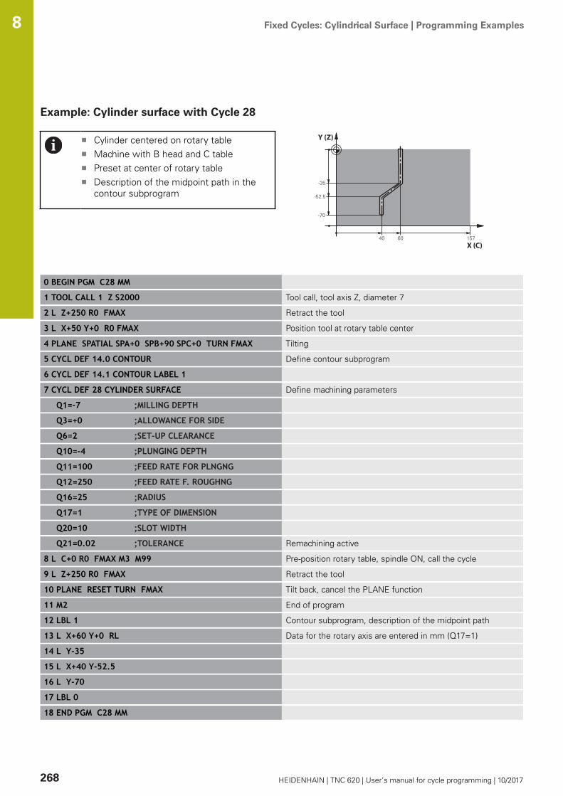
Fixed Cycles: Cylindrical Surface | Programming Examples 8
268 HEIDENHAIN | TNC 620 | User’s manual for cycle programming | 10/2017
Example: Cylinder surface with Cycle 28
Cylinder centered on rotary tableMachine with B head and C tablePreset at center of rotary tableDescription of the midpoint path in thecontour subprogram
Y (Z)
X (C)
0 BEGIN PGM C28 MM
1 TOOL CALL 1 Z S2000 Tool call, tool axis Z, diameter 7
2 L Z+250 R0 FMAX Retract the tool
3 L X+50 Y+0 R0 FMAX Position tool at rotary table center
4 PLANE SPATIAL SPA+0 SPB+90 SPC+0 TURN FMAX Tilting
5 CYCL DEF 14.0 CONTOUR Define contour subprogram
6 CYCL DEF 14.1 CONTOUR LABEL 1
7 CYCL DEF 28 CYLINDER SURFACE Define machining parameters
Q1=-7 ;MILLING DEPTH
Q3=+0 ;ALLOWANCE FOR SIDE
Q6=2 ;SET-UP CLEARANCE
Q10=-4 ;PLUNGING DEPTH
Q11=100 ;FEED RATE FOR PLNGNG
Q12=250 ;FEED RATE F. ROUGHNG
Q16=25 ;RADIUS
Q17=1 ;TYPE OF DIMENSION
Q20=10 ;SLOT WIDTH
Q21=0.02 ;TOLERANCE Remachining active
8 L C+0 R0 FMAX M3 M99 Pre-position rotary table, spindle ON, call the cycle
9 L Z+250 R0 FMAX Retract the tool
10 PLANE RESET TURN FMAX Tilt back, cancel the PLANE function
11 M2 End of program
12 LBL 1 Contour subprogram, description of the midpoint path
13 L X+60 Y+0 RL Data for the rotary axis are entered in mm (Q17=1)
14 L Y-35
15 L X+40 Y-52.5
16 L Y-70
17 LBL 0
18 END PGM C28 MM

9Fixed Cycles:
Contour Pocketwith Contour
Formula

Fixed Cycles: Contour Pocket with Contour Formula | SL cycles with complex contour formula 9
270 HEIDENHAIN | TNC 620 | User’s manual for cycle programming | 10/2017
9.1 SL cycles with complex contour formula
FundamentalsSL cycles and the complex contour formula enable you to formcomplex contours by combining subcontours (pockets or islands).You define the individual subcontours (geometry data) as separateprograms. In this way, any subcontour can be used any number oftimes. The TNC calculates the complete contour from the selectedsubcontours, which you link together through a contour formula.
The memory capacity for programming an SL cycle (allcontour description programs) is limited to 128 contours.The number of possible contour elements depends on thetype of contour (inside or outside contour) and the numberof contour descriptions. You can program up to 16384elements.The SL cycles with contour formula presuppose astructured program layout and enable you to savefrequently used contours in individual programs. Usingthe contour formula, you can connect the subcontoursto a complete contour and define whether it applies to apocket or island.In its present form, the "SL cycles with contour formula"function requires input from several areas in the TNC’suser interface. This function is to serve as a basis forfurther development.
Program structure: Machining withSL cycles and complex contourformula
0 BEGIN PGM CONTOUR MM
...
5 SEL CONTOUR “MODEL“
6 CYCL DEF 20 CONTOUR DATA ...
8 CYCL DEF 22 ROUGHING ...
9 CYCL CALL
...
12 CYCL DEF 23 FLOOR FINISHING ...
13 CYCL CALL
...
16 CYCL DEF 24 SIDE FINISHING ...
17 CYCL CALL
63 L Z+250 R0 FMAX M2
64 END PGM CONTOUR MM

Fixed Cycles: Contour Pocket with Contour Formula | SL cycles with complex contour formula 9
HEIDENHAIN | TNC 620 | User’s manual for cycle programming | 10/2017 271
Properties of the subcontours
By default, the TNC assumes that the contour is a pocket. Do notprogram a radius compensation.The TNC ignores feed rates F and miscellaneous functions M.Coordinate transformations are allowed. If they are programmedwithin the subcontour they are also effective in the followingsubprograms, but they need not be reset after the cycle call.Although the subprograms can contain coordinates in the spindleaxis, such coordinates are ignored.The working plane is defined in the first coordinate block of thesubprogram.You can define subcontours with various depths as needed
Characteristics of the fixed cycles
The TNC automatically positions the tool to the set-up clearancebefore a cycle.Each level of infeed depth is milled without interruptions since thecutter traverses around islands instead of over them.The radius of "inside corners" can be programmed—the toolkeeps moving to prevent surface blemishes at inside corners (thisapplies to the outermost pass in the Rough-out and Side Finishingcycles).The contour is approached in a tangential arc for side finishing.For floor finishing, the tool again approaches the workpiece on atangential arc (for spindle axis Z, for example, the arc may be inthe Z/X plane).The contour is machined throughout in either climb or up-cutmilling.
The machining data (such as milling depth, finishing allowance andset-up clearance) are entered as CONTOUR DATA in Cycle 20.
Program structure: Calculation of thesubcontours with contour formula
0 BEGIN PGM MODEL MM
1 DECLARE CONTOUR QC1 = “CIRCLE1”
2 DECLARE CONTOUR QC2 =“CIRCLEXY” DEPTH15
3 DECLARE CONTOUR QC3 =“TRIANGLE” DEPTH10
4 DECLARE CONTOUR QC4 = “SQUARE”DEPTH5
5 QC10 = ( QC1 | QC3 | QC4 ) \ QC2
6 END PGM MODEL MM
0 BEGIN PGM CIRCLE1 MM
1 CC X+75 Y+50
2 LP PR+45 PA+0
3 CP IPA+360 DR+
4 END PGM CIRCLE1 MM
0 BEGIN PGM CIRCLE31XY MM
...
...

Fixed Cycles: Contour Pocket with Contour Formula | SL cycles with complex contour formula 9
272 HEIDENHAIN | TNC 620 | User’s manual for cycle programming | 10/2017
Selecting a program with contour definitionsWith the SEL CONTOUR function you select a program with contourdefinitions, from which the TNC takes the contour descriptions:
Show the soft-key row with special functions
Menu for functions: Press the soft key forcontour and point machining
Press the SEL CONTOUR soft key.Enter the full name of the program with thecontour definitions and confirm with the ENDkey.
Program a SEL CONTOUR block before the SL cycles.Cycle 14 CONTOUR is no longer necessary if you useSEL CONTOUR.
Defining contour descriptionsWith the DECLARE CONTOUR function you enter in a programthe path for programs from which the TNC draws the contourdescriptions. In addition, you can select a separate depth for thiscontour description (FCL 2 function):
Show the soft-key row with special functions
Menu for functions: Press the soft key forcontour and point machining
Press the DECLARE CONTOUR soft key.Enter the number for the contour designator QC,and confirm with the ENT keyEnter the full name of the program with thecontour descriptions and confirm with the ENDkey, or if desired,Define a separate depth for the selected contour
With the entered contour designators QC you caninclude the various contours in the contour formula.If you program separate depths for contours, then youmust assign a depth to all subcontours (assign the depth0 if necessary).

Fixed Cycles: Contour Pocket with Contour Formula | SL cycles with complex contour formula 9
HEIDENHAIN | TNC 620 | User’s manual for cycle programming | 10/2017 273
Entering a complex contour formulaYou can use soft keys to interlink various contours in amathematical formula.
Show the soft-key row with special functions
Menu for functions: Press the soft key forcontour and point machining
Press the CONTOUR FORMULA soft key. TheTNC then displays the following soft keys:
Soft key Mathematical function
cut withe.g. QC10 = QC1 & QC5
joined withe.g. QC25 = QC7 | QC18
joined with, but without cute.g. QC12 = QC5 ^ QC25
withoute.g. QC25 = QC1 \ QC2
Parenthesis opene.g. QC12 = QC1 * (QC2 + QC3)
Parenthesis closede.g. QC12 = QC1 * (QC2 + QC3)
Define single contoure.g. QC12 = QC1

Fixed Cycles: Contour Pocket with Contour Formula | SL cycles with complex contour formula 9
274 HEIDENHAIN | TNC 620 | User’s manual for cycle programming | 10/2017
Superimposed contoursBy default, the TNC considers a programmed contour to be apocket. With the functions of the contour formula, you can converta contour from a pocket to an island.Pockets and islands can be overlapped to form a new contour. Youcan thus enlarge the area of a pocket by another pocket or reduce itby an island.
Subprograms: overlapping pockets
The following programming examples are contourdescription programs that are defined in a contourdefinition program The contour definition program iscalled through the SEL CONTOUR function in the actualmain program.
Pockets A and B overlap.The TNC calculates the points of intersection S1 and S2 (they donot have to be programmed).The pockets are programmed as full circles.
Contour description program 1: pocket A
0 BEGIN PGM POCKET_A MM
1 L X+10 Y+50 R0
2 CC X+35 Y+50
3 C X+10 Y+50 DR-
4 END PGM POCKET_A MM
Contour description program 2: pocket B
0 BEGIN PGM POCKET_B MM
1 L X+90 Y+50 R0
2 CC X+65 Y+50
3 C X+90 Y+50 DR-
4 END PGM POCKET_A MM
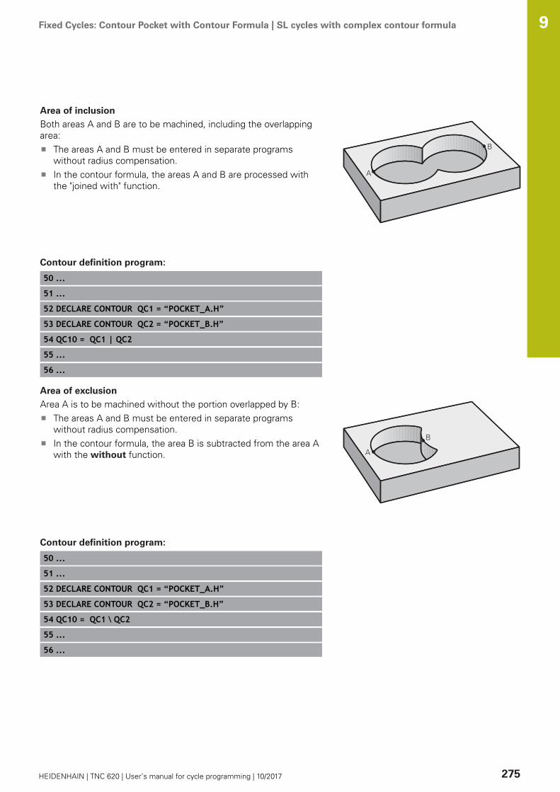
Fixed Cycles: Contour Pocket with Contour Formula | SL cycles with complex contour formula 9
HEIDENHAIN | TNC 620 | User’s manual for cycle programming | 10/2017 275
Area of inclusion
Both areas A and B are to be machined, including the overlappingarea:
The areas A and B must be entered in separate programswithout radius compensation.In the contour formula, the areas A and B are processed withthe "joined with" function.
Contour definition program:
50 ...
51 ...
52 DECLARE CONTOUR QC1 = “POCKET_A.H”
53 DECLARE CONTOUR QC2 = “POCKET_B.H”
54 QC10 = QC1 | QC2
55 ...
56 ...
Area of exclusion
Area A is to be machined without the portion overlapped by B:The areas A and B must be entered in separate programswithout radius compensation.In the contour formula, the area B is subtracted from the area Awith the without function.
Contour definition program:
50 ...
51 ...
52 DECLARE CONTOUR QC1 = “POCKET_A.H”
53 DECLARE CONTOUR QC2 = “POCKET_B.H”
54 QC10 = QC1 \ QC2
55 ...
56 ...

Fixed Cycles: Contour Pocket with Contour Formula | SL cycles with complex contour formula 9
276 HEIDENHAIN | TNC 620 | User’s manual for cycle programming | 10/2017
Area of intersection
Only the area where A and B overlap is to be machined. (The areascovered by A or B alone are to be left unmachined.)
The areas A and B must be entered in separate programswithout radius compensation.In the contour formula, the areas A and B are processed withthe "intersection with" function.
Contour definition program:
50 ...
51 ...
52 DECLARE CONTOUR QC1 = “POCKET_A.H”
53 DECLARE CONTOUR QC2 = “POCKET_B.H”
54 QC10 = QC1 & QC2
55 ...
56 ...
Contour machining with SL Cycles
The complete contour is machined with the SL Cycles20 to 24 (see "Overview", Page 210).

Fixed Cycles: Contour Pocket with Contour Formula | SL cycles with complex contour formula 9
HEIDENHAIN | TNC 620 | User’s manual for cycle programming | 10/2017 277
Example: Roughing and finishing superimposedcontours with the contour formula
0 BEGIN PGM CONTOUR MM
1 BLK FORM 0.1 Z X+0 Y+0 Z-40 Definition of workpiece blank
2 BLK FORM 0.2 X+100 Y+100 Z+0
3 TOOL DEF 1 L+0 R+2.5 Tool definition of roughing cutter
4 TOOL DEF 2 L+0 R+3 Tool definition of finishing cutter
5 TOOL CALL 1 Z S2500 Tool call of roughing cutter
6 L Z+250 R0 FMAX Retract the tool
7 SEL CONTOUR “MODEL“ Specify contour definition program
8 CYCL DEF 20 CONTOUR DATA Define general machining parameters
Q1=-20 ;MILLING DEPTH
Q2=1 ;TOOL PATH OVERLAP
Q3=+0.5 ;ALLOWANCE FOR SIDE
Q4=+0.5 ;ALLOWANCE FOR FLOOR
Q5=+0 ;SURFACE COORDINATE
Q6=2 ;SET-UP CLEARANCE
Q7=+100 ;CLEARANCE HEIGHT
Q8=0.1 ;ROUNDING RADIUS
Q9=-1 ;ROTATIONAL DIRECTION
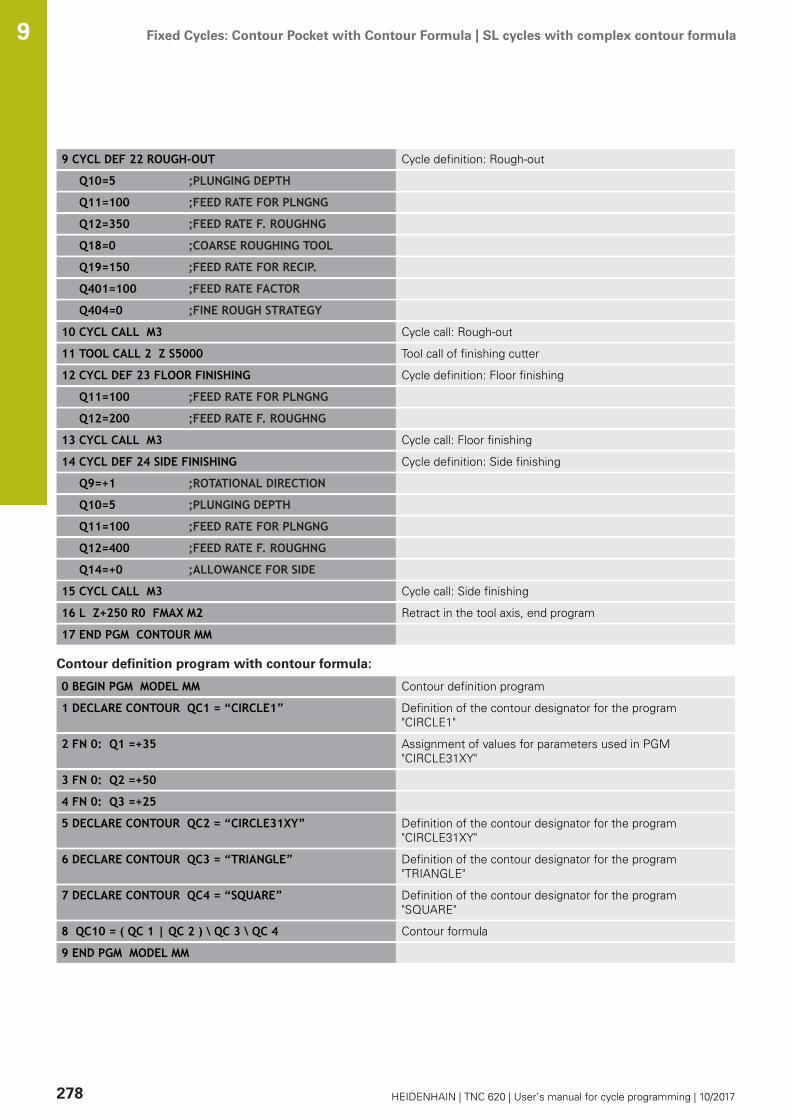
Fixed Cycles: Contour Pocket with Contour Formula | SL cycles with complex contour formula 9
278 HEIDENHAIN | TNC 620 | User’s manual for cycle programming | 10/2017
9 CYCL DEF 22 ROUGH-OUT Cycle definition: Rough-out
Q10=5 ;PLUNGING DEPTH
Q11=100 ;FEED RATE FOR PLNGNG
Q12=350 ;FEED RATE F. ROUGHNG
Q18=0 ;COARSE ROUGHING TOOL
Q19=150 ;FEED RATE FOR RECIP.
Q401=100 ;FEED RATE FACTOR
Q404=0 ;FINE ROUGH STRATEGY
10 CYCL CALL M3 Cycle call: Rough-out
11 TOOL CALL 2 Z S5000 Tool call of finishing cutter
12 CYCL DEF 23 FLOOR FINISHING Cycle definition: Floor finishing
Q11=100 ;FEED RATE FOR PLNGNG
Q12=200 ;FEED RATE F. ROUGHNG
13 CYCL CALL M3 Cycle call: Floor finishing
14 CYCL DEF 24 SIDE FINISHING Cycle definition: Side finishing
Q9=+1 ;ROTATIONAL DIRECTION
Q10=5 ;PLUNGING DEPTH
Q11=100 ;FEED RATE FOR PLNGNG
Q12=400 ;FEED RATE F. ROUGHNG
Q14=+0 ;ALLOWANCE FOR SIDE
15 CYCL CALL M3 Cycle call: Side finishing
16 L Z+250 R0 FMAX M2 Retract in the tool axis, end program
17 END PGM CONTOUR MM
Contour definition program with contour formula:
0 BEGIN PGM MODEL MM Contour definition program
1 DECLARE CONTOUR QC1 = “CIRCLE1” Definition of the contour designator for the program"CIRCLE1"
2 FN 0: Q1 =+35 Assignment of values for parameters used in PGM"CIRCLE31XY"
3 FN 0: Q2 =+50
4 FN 0: Q3 =+25
5 DECLARE CONTOUR QC2 = “CIRCLE31XY” Definition of the contour designator for the program"CIRCLE31XY"
6 DECLARE CONTOUR QC3 = “TRIANGLE” Definition of the contour designator for the program"TRIANGLE"
7 DECLARE CONTOUR QC4 = “SQUARE” Definition of the contour designator for the program"SQUARE"
8 QC10 = ( QC 1 | QC 2 ) \ QC 3 \ QC 4 Contour formula
9 END PGM MODEL MM

Fixed Cycles: Contour Pocket with Contour Formula | SL cycles with complex contour formula 9
HEIDENHAIN | TNC 620 | User’s manual for cycle programming | 10/2017 279
Contour description programs:
0 BEGIN PGM CIRCLE1 MM Contour description program: circle at right
1 CC X+65 Y+50
2 L PR+25 PA+0 R0
3 CP IPA+360 DR+
4 END PGM CIRCLE1 MM
0 BEGIN PGM CIRCLE31XY MM Contour description program: circle at left
1 CC X+Q1 Y+Q2
2 LP PR+Q3 PA+0 R0
3 CP IPA+360 DR+
4 END PGM CIRCLE31XY MM
0 BEGIN PGM TRIANGLE MM Contour description program: triangle at right
1 L X+73 Y+42 R0
2 L X+65 Y+58
3 L X+58 Y+42
4 L X+73
5 END PGM TRIANGLE MM
0 BEGIN PGM SQUARE MM Contour description program: square at left
1 L X+27 Y+58 R0
2 L X+43
3 L Y+42
4 L X+27
5 L Y+58
6 END PGM SQUARE MM

Fixed Cycles: Contour Pocket with Contour Formula | SL cycles with simple contour formula 9
280 HEIDENHAIN | TNC 620 | User’s manual for cycle programming | 10/2017
9.2 SL cycles with simple contour formula
FundamentalsSL cycles and the simple contour formula enable you to formcontours by combining up to 9 subcontours (pockets or islands) ina simple manner. You define the individual subcontours (geometrydata) as separate programs. In this way, any subcontour can beused any number of times. The TNC calculates the contour from theselected subcontours.
The memory capacity for programming an SL cycle (allcontour description programs) is limited to 128 contours.The number of possible contour elements depends on thetype of contour (inside or outside contour) and the numberof contour descriptions. You can program up to 16384elements.
Program structure: Machining withSL cycles and complex contourformula
0 BEGIN PGM CONTDEF MM
...
5 CONTOUR DEF P1= “POCK1.H“ I2 =“ISLE2.H“ DEPTH5 I3 “ISLE3.H“DEPTH7.5
6 CYCL DEF 20 CONTOUR DATA ...
8 CYCL DEF 22 ROUGHING ...
9 CYCL CALL
...
12 CYCL DEF 23 FLOOR FINISHING ...
13 CYCL CALL
...
16 CYCL DEF 24 SIDE FINISHING ...
17 CYCL CALL
63 L Z+250 R0 FMAX M2
64 END PGM CONTDEF MM
Fixed Cycles: Contour Pocket with Contour Formula | SL cycles with simple contour formula 9
HEIDENHAIN | TNC 620 | User’s manual for cycle programming | 10/2017 281
Properties of the subcontours
Do not program a radius compensation.The TNC ignores feed rates F and miscellaneous functions M.Coordinate transformations are allowed. If they are programmedwithin the subcontour they are also effective in the followingsubprograms, but they need not be reset after the cycle call.Although the subprograms can contain coordinates in thespindle axis, such coordinates are ignored.The working plane is defined in the first coordinate block of thesubprogram.
Characteristics of the fixed cycles
The TNC automatically positions the tool to the set-up clearancebefore a cycle.Each level of infeed depth is milled without interruptions sincethe cutter traverses around islands instead of over them.The radius of "inside corners" can be programmed—the toolkeeps moving to prevent surface blemishes at inside corners(this applies to the outermost pass in the Rough-out and SideFinishing cycles).The contour is approached in a tangential arc for side finishing.For floor finishing, the tool again approaches the workpiece on atangential arc (for spindle axis Z, for example, the arc may be inthe Z/X plane).The contour is machined throughout in either climb or up-cutmilling.
The machining data (such as milling depth, finishing allowance andset-up clearance) are entered as CONTOUR DATA in Cycle 20.
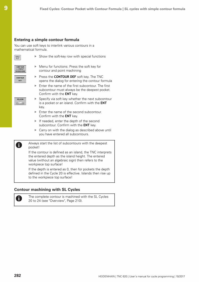
Fixed Cycles: Contour Pocket with Contour Formula | SL cycles with simple contour formula 9
282 HEIDENHAIN | TNC 620 | User’s manual for cycle programming | 10/2017
Entering a simple contour formulaYou can use soft keys to interlink various contours in amathematical formula.
Show the soft-key row with special functions
Menu for functions: Press the soft key forcontour and point machining
Press the CONTOUR DEF soft key. The TNCopens the dialog for entering the contour formulaEnter the name of the first subcontour. The firstsubcontour must always be the deepest pocket.Confirm with the ENT key.Specify via soft key whether the next subcontouris a pocket or an island. Confirm with the ENTkey.Enter the name of the second subcontour.Confirm with the ENT key.If needed, enter the depth of the secondsubcontour. Confirm with the ENT key.Carry on with the dialog as described above untilyou have entered all subcontours.
Always start the list of subcontours with the deepestpocket!If the contour is defined as an island, the TNC interpretsthe entered depth as the island height. The enteredvalue (without an algebraic sign) then refers to theworkpiece top surface!If the depth is entered as 0, then for pockets the depthdefined in the Cycle 20 is effective. Islands then rise upto the workpiece top surface!
Contour machining with SL Cycles
The complete contour is machined with the SL Cycles20 to 24 (see "Overview", Page 210).

10Cycles: Coordinate
Transformations

Cycles: Coordinate Transformations | Fundamentals 10
284 HEIDENHAIN | TNC 620 | User’s manual for cycle programming | 10/2017
10.1 Fundamentals
OverviewOnce a contour has been programmed, you can position it on theworkpiece at various locations and in different sizes through theuse of coordinate transformations. The TNC provides the followingcoordinate transformation cycles:
Soft key Cycle Page
7 DATUM SHIFTFor shifting contours directly withinthe program or from datum tables
285
247 PRESETTING Presetting during program run
291
8 MIRRORING Mirroring contours
292
10 ROTATION Rotating contours in the workingplane
294
11 SCALING FACTOR
Increasing or reducing the size ofcontours
296
26 AXIS-SPECIFIC SCALINGIncreasing or reducing the size ofcontours with axis-specific scaling
297
19 WORKING PLANE Machin-ing in tilted coordinate system onmachines with swivel heads and/orrotary tables
299
Effectiveness of coordinate transformationsBeginning of effect: A coordinate transformation becomes effectiveas soon as it is defined—it is not called separately. It remains ineffect until it is changed or canceled.Reset coordinate transformation:
Define cycles for basic behavior with a new value, such asscaling factor 1.0Execute a miscellaneous function M2, M30, or an END PGMblock (depending on machine parameter clearMode)Select a new program

Cycles: Coordinate Transformations | DATUM SHIFT (Cycle 7, DIN/ISO: G54) 10
HEIDENHAIN | TNC 620 | User’s manual for cycle programming | 10/2017 285
10.2 DATUM SHIFT (Cycle 7, DIN/ISO: G54)
EffectA datum shift allows machining operations to be repeated atvarious locations on the workpiece.When the datum shift cycle is defined, all coordinate data is basedon the new datum. The TNC displays the datum shift in each axis inthe additional status display. Input of rotary axes is also permitted.Resetting
Program a datum shift to the coordinates X=0, Y=0 etc. directlywith a cycle definition.Call a datum shift to the coordinates X=0; Y=0 etc. from adatum table.
Cycle parametersDisplacement: Enter the coordinates of the newdatum. Absolute values are referenced to theworkpiece datum, which is specified by presetting.Incremental values are always referenced to thedatum which was last valid—this can be a datumwhich has already been shifted. Input range:Up to six NC axes, each from –99999.9999 to99999.9999
NC blocks
13 CYCL DEF 7.0 DATUM SHIFT
14 CYCL DEF 7.1 X+60
15 CYCL DEF 7.2 Y+40
16 CYCL DEF 7.3 Z-5
Please note while programming
In the optional machine parameter CfgDisplayCoordSys(no. 127501) you can specify the coordinate system inwhich the status display shows an active datum shift.
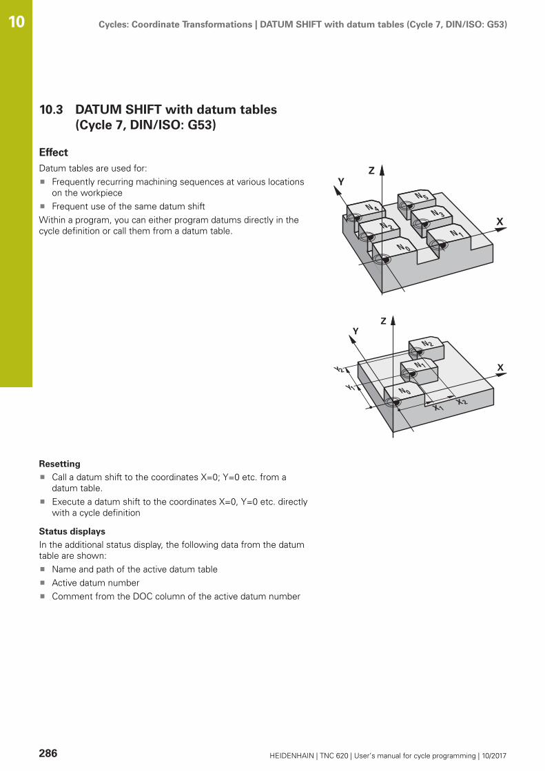
Cycles: Coordinate Transformations | DATUM SHIFT with datum tables (Cycle 7, DIN/ISO: G53) 10
286 HEIDENHAIN | TNC 620 | User’s manual for cycle programming | 10/2017
10.3 DATUM SHIFT with datum tables(Cycle 7, DIN/ISO: G53)
EffectDatum tables are used for:
Frequently recurring machining sequences at various locationson the workpieceFrequent use of the same datum shift
Within a program, you can either program datums directly in thecycle definition or call them from a datum table.
Resetting
Call a datum shift to the coordinates X=0; Y=0 etc. from adatum table.Execute a datum shift to the coordinates X=0, Y=0 etc. directlywith a cycle definition
Status displays
In the additional status display, the following data from the datumtable are shown:
Name and path of the active datum tableActive datum numberComment from the DOC column of the active datum number

Cycles: Coordinate Transformations | DATUM SHIFT with datum tables (Cycle 7, DIN/ISO: G53) 10
HEIDENHAIN | TNC 620 | User’s manual for cycle programming | 10/2017 287
Please note while programming:
Datums from a datum table are always and exclusivelyreferenced to the current preset.If you are using datum shifts with datum tables, thenuse the SEL TABLE function to activate the desireddatum table from the NC program.In the optional machine parameter CfgDisplayCoordSys(no. 127501) you can specify the coordinate system inwhich the status display shows an active datum shift.If you work without SEL TABLE, then you must activatethe desired datum table before the test run or theprogram run. (This applies also to the programminggraphics).
Use the file management to select the desired tablefor a test run in the Test Run operating mode: Thetable receives the status SUse the file management to select the desired tablefor the program run in the Program run, single blockand Program run, full sequence operating modes:The table receives the status M
The coordinate values from datum tables are onlyeffective with absolute coordinate values.New lines can only be inserted at the end of the table.If you create datum tables, the file name has to startwith a letter.
Cycle parametersDisplacement: Enter the number of the datumfrom the datum table or a Q parameter. If youenter a Q parameter, the TNC activates the datumnumber entered in the Q parameter. Input range 0to 9999
NC blocks
77 CYCL DEF 7.0 DATUM SHIFT
78 CYCL DEF 7.1 #5

Cycles: Coordinate Transformations | DATUM SHIFT with datum tables (Cycle 7, DIN/ISO: G53) 10
288 HEIDENHAIN | TNC 620 | User’s manual for cycle programming | 10/2017
Selecting a datum table in the part programWith the SEL TABLE function you select the table from which theTNC takes the datums:
To select the functions for program call, pressthe PGM CALL key
Press the DATUM TABLE soft keySelect the complete path name of the datumtable or the file with the SELECT soft key andconfirm your entry with the END key
Program a SEL TABLE block before Cycle 7 Datum Shift.A datum table selected with SEL TABLE remains activeuntil you select another datum table with SEL TABLE orthrough PGM MGT.
Editing the datum table in the Programming mode ofoperation
After you have changed a value in a datum table, youmust save the change with the ENT key. Otherwise thechange might not be included during program run.
Select the datum table in the mode of operation Programming
To call the file manager, press the PGM MGT key.Display the datum tables: Press theSELECT TYPE and SHOW .D soft keysSelect the desired table or enter a new filename.Edit the file. The functions displayed in the soft-key row for editing include:

Cycles: Coordinate Transformations | DATUM SHIFT with datum tables (Cycle 7, DIN/ISO: G53) 10
HEIDENHAIN | TNC 620 | User’s manual for cycle programming | 10/2017 289
Soft key Function
Select beginning of table
Select the table end
Go to previous page
Go to next page
Insert line (only possible at the end of table)
Delete line
Find
Go to beginning of line
Go to end of line
Copy the current value
Insert the copied value
Add the entered number of lines (datums) tothe end of the table
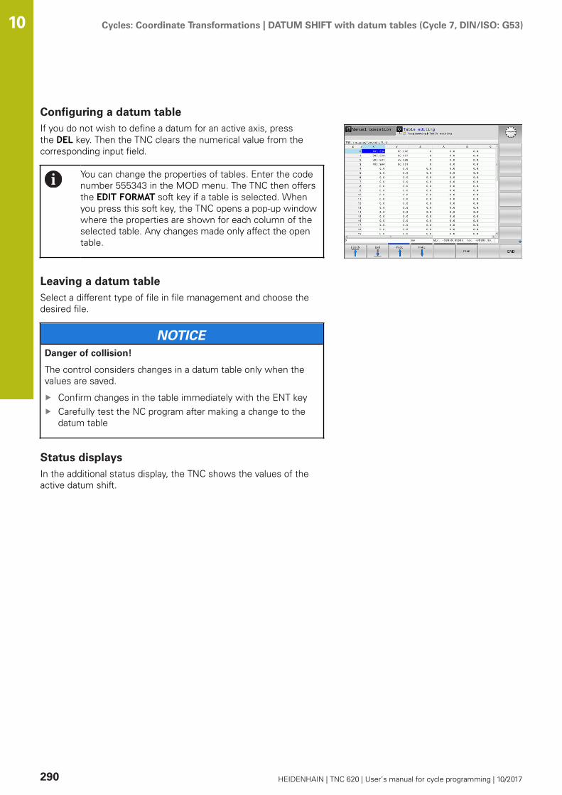
Cycles: Coordinate Transformations | DATUM SHIFT with datum tables (Cycle 7, DIN/ISO: G53) 10
290 HEIDENHAIN | TNC 620 | User’s manual for cycle programming | 10/2017
Configuring a datum tableIf you do not wish to define a datum for an active axis, pressthe DEL key. Then the TNC clears the numerical value from thecorresponding input field.
You can change the properties of tables. Enter the codenumber 555343 in the MOD menu. The TNC then offersthe EDIT FORMAT soft key if a table is selected. Whenyou press this soft key, the TNC opens a pop-up windowwhere the properties are shown for each column of theselected table. Any changes made only affect the opentable.
Leaving a datum tableSelect a different type of file in file management and choose thedesired file.
NOTICEDanger of collision!
The control considers changes in a datum table only when thevalues are saved.
Confirm changes in the table immediately with the ENT keyCarefully test the NC program after making a change to thedatum table
Status displaysIn the additional status display, the TNC shows the values of theactive datum shift.

Cycles: Coordinate Transformations | PRESETTING (Cycle 247, DIN/ISO: G247) 10
HEIDENHAIN | TNC 620 | User’s manual for cycle programming | 10/2017 291
10.4 PRESETTING (Cycle 247, DIN/ISO: G247)
EffectWith the presetting cycle you can activate as the new preset apreset defined in the preset table.After a presetting cycle definition, all of the coordinate inputs anddatum shifts (absolute and incremental) are referenced to the newpreset.Status display
In the status display the TNC shows the active preset numberbehind the preset symbol.
Please note before programming:
When activating a preset from the preset table, the TNCresets the datum shift, mirroring, rotation, scaling factorand axis-specific scaling factor.If you activate preset number 0 (row 0), then youactivate the preset that you last set in Manual operationor Electronic handwheel operating mode.Cycle 247 is also effective in the Test Run mode ofoperation.
Cycle parametersNumber for preset?: Enter the number of thedesired preset from the preset table. As analternative, you can also select the desired presetdirectly from the preset table with SELECT. Inputrange 0 to 65535
NC blocks
13 CYCL DEF 247 PRESETTING
Q339=4 ;PRESET NUMBER
Status displaysIn the additional status display (STATUS POS.) the TNC shows theactive preset number behind the Preset dialog.
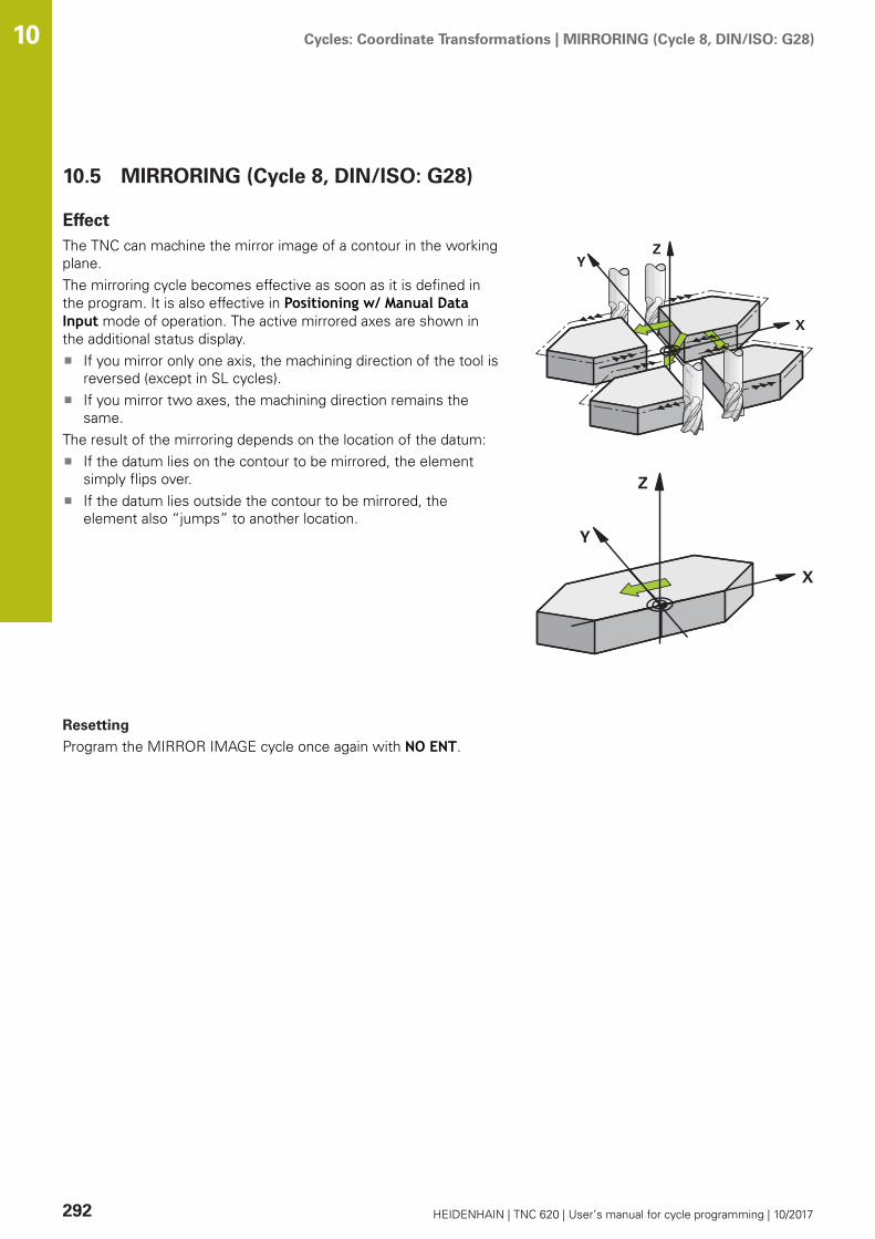
Cycles: Coordinate Transformations | MIRRORING (Cycle 8, DIN/ISO: G28) 10
292 HEIDENHAIN | TNC 620 | User’s manual for cycle programming | 10/2017
10.5 MIRRORING (Cycle 8, DIN/ISO: G28)
EffectThe TNC can machine the mirror image of a contour in the workingplane.The mirroring cycle becomes effective as soon as it is defined inthe program. It is also effective in Positioning w/ Manual DataInput mode of operation. The active mirrored axes are shown inthe additional status display.
If you mirror only one axis, the machining direction of the tool isreversed (except in SL cycles).If you mirror two axes, the machining direction remains thesame.
The result of the mirroring depends on the location of the datum:If the datum lies on the contour to be mirrored, the elementsimply flips over.If the datum lies outside the contour to be mirrored, theelement also “jumps” to another location.
Resetting
Program the MIRROR IMAGE cycle once again with NO ENT.
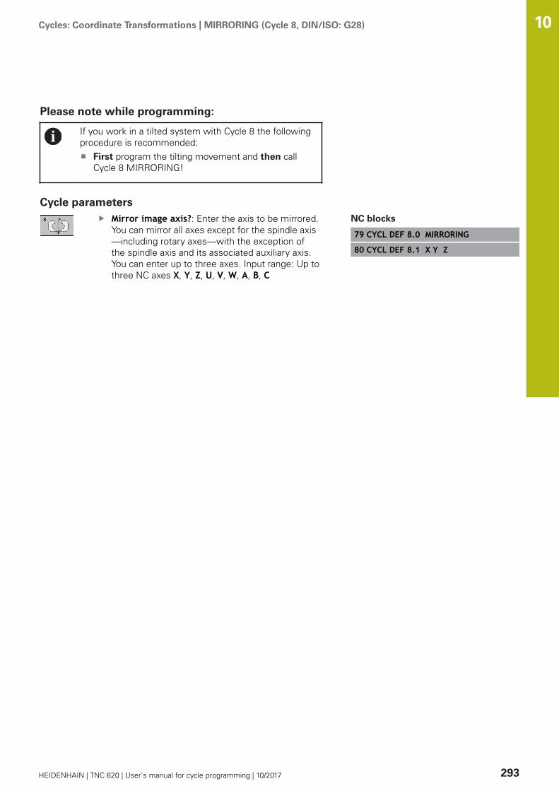
Cycles: Coordinate Transformations | MIRRORING (Cycle 8, DIN/ISO: G28) 10
HEIDENHAIN | TNC 620 | User’s manual for cycle programming | 10/2017 293
Please note while programming:
If you work in a tilted system with Cycle 8 the followingprocedure is recommended:
First program the tilting movement and then callCycle 8 MIRRORING!
Cycle parametersMirror image axis?: Enter the axis to be mirrored.You can mirror all axes except for the spindle axis—including rotary axes—with the exception ofthe spindle axis and its associated auxiliary axis.You can enter up to three axes. Input range: Up tothree NC axes X, Y, Z, U, V, W, A, B, C
NC blocks
79 CYCL DEF 8.0 MIRRORING
80 CYCL DEF 8.1 X Y Z
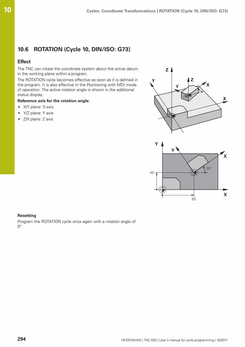
Cycles: Coordinate Transformations | ROTATION (Cycle 10, DIN/ISO: G73) 10
294 HEIDENHAIN | TNC 620 | User’s manual for cycle programming | 10/2017
10.6 ROTATION (Cycle 10, DIN/ISO: G73)
EffectThe TNC can rotate the coordinate system about the active datumin the working plane within a program.The ROTATION cycle becomes effective as soon as it is defined inthe program. It is also effective in the Positioning with MDI modeof operation. The active rotation angle is shown in the additionalstatus display.Reference axis for the rotation angle:
X/Y plane: X axisY/Z plane: Y axisZ/X plane: Z axis
Resetting
Program the ROTATION cycle once again with a rotation angle of0°.

Cycles: Coordinate Transformations | ROTATION (Cycle 10, DIN/ISO: G73) 10
HEIDENHAIN | TNC 620 | User’s manual for cycle programming | 10/2017 295
Please note while programming:
An active radius compensation is canceled by definingCycle 10 and must therefore be reprogrammed, ifnecessary.After defining Cycle 10, you must move both axes of theworking plane to activate rotation for all axes.
Cycle parametersRotation: Enter the rotation angle in degrees (°).Input range –360.000° to +360.000° (absolute orincremental)
NC blocks
12 CALL LBL 1
13 CYCL DEF 7.0 DATUM SHIFT
14 CYCL DEF 7.1 X+60
15 CYCL DEF 7.2 Y+40
16 CYCL DEF 10.0 ROTATION
17 CYCL DEF 10.1 ROT+35
18 CALL LBL 1
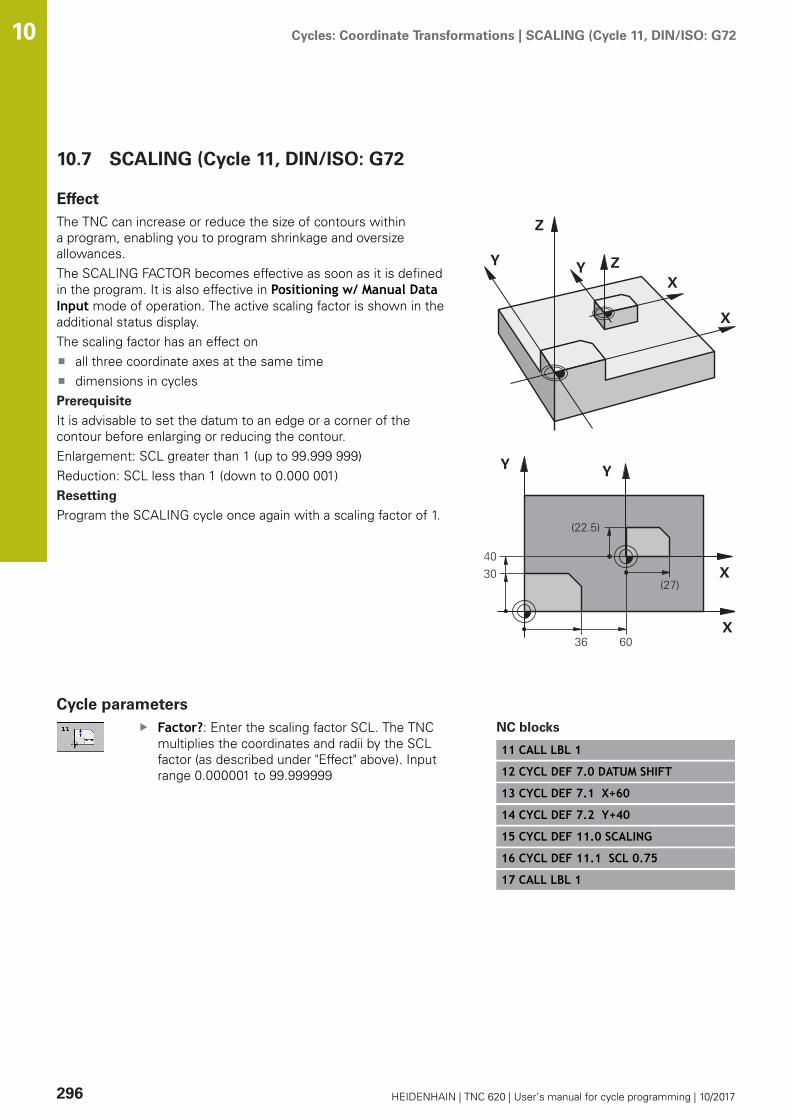
Cycles: Coordinate Transformations | SCALING (Cycle 11, DIN/ISO: G72 10
296 HEIDENHAIN | TNC 620 | User’s manual for cycle programming | 10/2017
10.7 SCALING (Cycle 11, DIN/ISO: G72
EffectThe TNC can increase or reduce the size of contours withina program, enabling you to program shrinkage and oversizeallowances.The SCALING FACTOR becomes effective as soon as it is definedin the program. It is also effective in Positioning w/ Manual DataInput mode of operation. The active scaling factor is shown in theadditional status display.The scaling factor has an effect on
all three coordinate axes at the same timedimensions in cycles
Prerequisite
It is advisable to set the datum to an edge or a corner of thecontour before enlarging or reducing the contour.Enlargement: SCL greater than 1 (up to 99.999 999)Reduction: SCL less than 1 (down to 0.000 001)Resetting
Program the SCALING cycle once again with a scaling factor of 1.
Cycle parametersFactor?: Enter the scaling factor SCL. The TNCmultiplies the coordinates and radii by the SCLfactor (as described under "Effect" above). Inputrange 0.000001 to 99.999999
NC blocks
11 CALL LBL 1
12 CYCL DEF 7.0 DATUM SHIFT
13 CYCL DEF 7.1 X+60
14 CYCL DEF 7.2 Y+40
15 CYCL DEF 11.0 SCALING
16 CYCL DEF 11.1 SCL 0.75
17 CALL LBL 1

Cycles: Coordinate Transformations | AXIS-SPECIFIC SCALING (Cycle 26) 10
HEIDENHAIN | TNC 620 | User’s manual for cycle programming | 10/2017 297
10.8 AXIS-SPECIFIC SCALING (Cycle 26)
EffectWith Cycle 26 you can account for shrinkage and oversize factorsfor each axis.The SCALING FACTOR becomes effective as soon as it is definedin the program. It is also effective in Positioning w/ Manual DataInput mode of operation. The active scaling factor is shown in theadditional status display.Resetting
Program the SCALING cycle once again with a scaling factor of 1for the same axis.
Please note while programming:
Coordinate axes sharing coordinates for arcs must beenlarged or reduced by the same factor.You can program each coordinate axis with its own axis-specific scaling factor.In addition, you can enter the coordinates of a center forall scaling factors.The size of the contour is enlarged or reduced withreference to the center, and not necessarily (as in Cycle11 SCALING) with reference to the active datum.
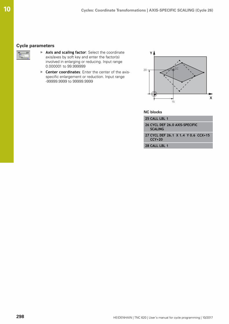
Cycles: Coordinate Transformations | AXIS-SPECIFIC SCALING (Cycle 26) 10
298 HEIDENHAIN | TNC 620 | User’s manual for cycle programming | 10/2017
Cycle parametersAxis and scaling factor: Select the coordinateaxis/axes by soft key and enter the factor(s)involved in enlarging or reducing. Input range0.000001 to 99.999999Center coordinates: Enter the center of the axis-specific enlargement or reduction. Input range-99999.9999 to 99999.9999
NC blocks
25 CALL LBL 1
26 CYCL DEF 26.0 AXIS-SPECIFICSCALING
27 CYCL DEF 26.1 X 1.4 Y 0.6 CCX+15CCY+20
28 CALL LBL 1
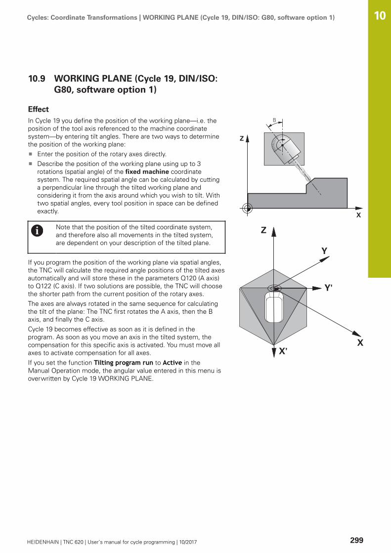
Cycles: Coordinate Transformations | WORKING PLANE (Cycle 19, DIN/ISO: G80, software option 1) 10
HEIDENHAIN | TNC 620 | User’s manual for cycle programming | 10/2017 299
10.9 WORKING PLANE (Cycle 19, DIN/ISO:G80, software option 1)
EffectIn Cycle 19 you define the position of the working plane—i.e. theposition of the tool axis referenced to the machine coordinatesystem—by entering tilt angles. There are two ways to determinethe position of the working plane:
Enter the position of the rotary axes directly.Describe the position of the working plane using up to 3rotations (spatial angle) of the fixed machine coordinatesystem. The required spatial angle can be calculated by cuttinga perpendicular line through the tilted working plane andconsidering it from the axis around which you wish to tilt. Withtwo spatial angles, every tool position in space can be definedexactly.
Note that the position of the tilted coordinate system,and therefore also all movements in the tilted system,are dependent on your description of the tilted plane.
If you program the position of the working plane via spatial angles,the TNC will calculate the required angle positions of the tilted axesautomatically and will store these in the parameters Q120 (A axis)to Q122 (C axis). If two solutions are possible, the TNC will choosethe shorter path from the current position of the rotary axes.The axes are always rotated in the same sequence for calculatingthe tilt of the plane: The TNC first rotates the A axis, then the Baxis, and finally the C axis.Cycle 19 becomes effective as soon as it is defined in theprogram. As soon as you move an axis in the tilted system, thecompensation for this specific axis is activated. You must move allaxes to activate compensation for all axes.If you set the function Tilting program run to Active in theManual Operation mode, the angular value entered in this menu isoverwritten by Cycle 19 WORKING PLANE.

Cycles: Coordinate Transformations | WORKING PLANE (Cycle 19, DIN/ISO: G80, software option 1) 10
300 HEIDENHAIN | TNC 620 | User’s manual for cycle programming | 10/2017
Please note while programming:
The Tilt working plane functions are interfaced to thecontrol and the machine tool by the machine tool builder.The machine tool builder also specifies whether theprogrammed angles are interpreted as coordinates ofthe rotary axes (axis angles) or as angular componentsof a tilted plane (spatial angles).
Because nonprogrammed rotary axis values areinterpreted as unchanged, you should always define allthree spatial angles, even if one or more angles are atzero.The working plane is always tilted around the activedatum.If you use Cycle 19 when M120 is active, the TNCautomatically rescinds the radius compensation, whichalso rescinds the M120 function.In the optional machine parameter CfgDisplayCoordSys(no. 127501) you can specify the coordinate system inwhich the status display shows an active datum shift.
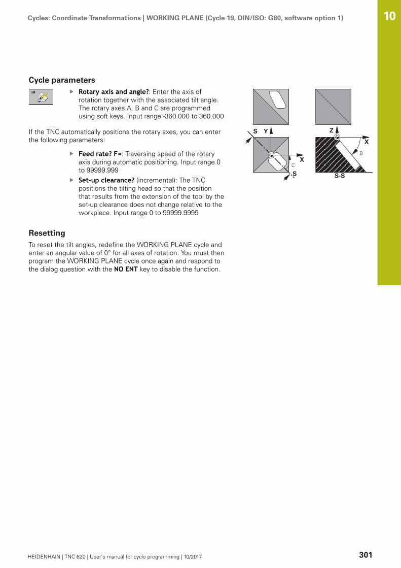
Cycles: Coordinate Transformations | WORKING PLANE (Cycle 19, DIN/ISO: G80, software option 1) 10
HEIDENHAIN | TNC 620 | User’s manual for cycle programming | 10/2017 301
Cycle parametersRotary axis and angle?: Enter the axis ofrotation together with the associated tilt angle.The rotary axes A, B and C are programmedusing soft keys. Input range -360.000 to 360.000
If the TNC automatically positions the rotary axes, you can enterthe following parameters:
Feed rate? F=: Traversing speed of the rotaryaxis during automatic positioning. Input range 0to 99999.999Set-up clearance? (incremental): The TNCpositions the tilting head so that the positionthat results from the extension of the tool by theset-up clearance does not change relative to theworkpiece. Input range 0 to 99999.9999
ResettingTo reset the tilt angles, redefine the WORKING PLANE cycle andenter an angular value of 0° for all axes of rotation. You must thenprogram the WORKING PLANE cycle once again and respond tothe dialog question with the NO ENT key to disable the function.

Cycles: Coordinate Transformations | WORKING PLANE (Cycle 19, DIN/ISO: G80, software option 1) 10
302 HEIDENHAIN | TNC 620 | User’s manual for cycle programming | 10/2017
Positioning the axes of rotation
Refer to your machine manual.The machine tool builder determines whether Cycle 19positions the axes of rotation automatically or whetherthey must be positioned manually in the program.
Manual positioning of rotary axes
If the rotary axes are not positioned automatically in Cycle 19, youmust position them in a separate L block after the cycle definition.If you use axis angles, you can define the axis values right in the Lblock. If you use spatial angles, then use the Q parameters Q120(A-axis value), Q121 (B-axis value) and Q122 (C-axis value), whichare described by Cycle 19.
For manual positioning, always use the rotary axispositions stored in Q parameters Q120 to Q122.Avoid using functions, such as M94 (modulo rotaryaxes), in order to avoid discrepancies between theactual and nominal positions of rotary axes in multipledefinitions.
Example NC blocks:
10 L Z+100 R0 FMAX
11 L X+25 Y+10 R0 FMAX
12 CYCL DEF 19.0 WORKING PLANE Define the spatial angle for calculation of the compensation
13 CYCL DEF 19.1 A+0 B+45 C+0
14 L A+Q120 C+Q122 R0 F1000 Position the rotary axes by using values calculated by Cycle19
15 L Z+80 R0 FMAX Activate compensation for the spindle axis
16 L X-8.5 Y-10 R0 FMAX Activate compensation for the working plane

Cycles: Coordinate Transformations | WORKING PLANE (Cycle 19, DIN/ISO: G80, software option 1) 10
HEIDENHAIN | TNC 620 | User’s manual for cycle programming | 10/2017 303
Automatic positioning of rotary axes
If the rotary axes are positioned automatically in Cycle 19:The TNC can position only controlled axesIn order for the tilted axes to be positioned, you must enter afeed rate and a set-up clearance in addition to the tilting angles,during cycle definition.Use only preset tools (the full tool length must be defined).The position of the tool tip as referenced to the workpiecesurface remains nearly unchanged after tiltingThe TNC performs the tilt at the last programmed feed rate.The maximum feed rate that can be reached depends on thecomplexity of the swivel head or tilting table.
Example NC blocks:
10 L Z+100 R0 FMAX
11 L X+25 Y+10 R0 FMAX
12 CYCL DEF 19.0 WORKING PLANE Define the angle for calculation of the compensation
13 CYCL DEF 19.1 A+0 B+45 C+0 F5000 ABST50 Also define the feed rate and the clearance
14 L Z+80 R0 FMAX Activate compensation for the spindle axis
15 L X-8.5 Y-10 R0 FMAX Activate compensation for the working plane
Position display in a tilted systemOn activation of Cycle 19, the displayed positions (ACTL andNOML) and the datum indicated in the additional status display arereferenced to the tilted coordinate system. The positions displayedimmediately after cycle definition might not be the same as thecoordinates of the last programmed position before Cycle 19.
Monitoring of the working spaceThe TNC checks only those axes in the tilted coordinate systemthat are moved. If necessary, the TNC outputs an error message.

Cycles: Coordinate Transformations | WORKING PLANE (Cycle 19, DIN/ISO: G80, software option 1) 10
304 HEIDENHAIN | TNC 620 | User’s manual for cycle programming | 10/2017
Positioning in a tilted coordinate systemWith the miscellaneous function M130 you can move the tool,while the coordinate system is tilted, to positions that arereferenced to the non-tilted coordinate system.Positioning movements with straight lines that are referenced tothe machine coordinate system (blocks with M91 or M92) can alsobe executed in a tilted working plane. Constraints:
Positioning is without length compensation.Positioning is without machine geometry compensation.Tool radius compensation is not permitted.
Combining coordinate transformation cyclesWhen combining coordinate transformation cycles, always makesure the working plane is swiveled around the active datum. Youcan program a datum shift before activating Cycle 19. In this case,you are shifting the machine-based coordinate system.If you program a datum shift after having activated Cycle 19, youare shifting the tilted coordinate system.Important: When resetting the cycles, use the reverse sequenceused for defining them:
1st Activate datum shift2nd Activate tilting function3rd Activate rotation...Workpiece machining...1st Reset rotation2nd Reset tilting function3rd Reset datum shift

Cycles: Coordinate Transformations | WORKING PLANE (Cycle 19, DIN/ISO: G80, software option 1) 10
HEIDENHAIN | TNC 620 | User’s manual for cycle programming | 10/2017 305
Procedure for working with Cycle 19 WORKING PLANE1 Write the program
Define the tool (not required if TOOL.T is active), and enter thefull tool length.Call the tool.Retract the tool in the tool axis to a position where there isno danger of collision with the workpiece or clamping devicesduring tilting.If required, position the tilt axis or axes with an L block tothe appropriate angular value(s) (depending on a machineparameter).Activate datum shift if required.Define Cycle 19 WORKING PLANE; enter the angular values forthe tilt axesTraverse all principal axes (X, Y, Z) to activate compensation.Write the program as if the machining process were to beexecuted in a non-tilted plane.If required, define Cycle 19 WORKING PLANE with otherangular values to execute machining in a different axis position.In this case, it is not necessary to reset Cycle 19. You can definethe new angular values directly.Reset Cycle 19 WORKING PLANE; program 0° for all tilt axes.Disable the WORKING PLANE function; redefine Cycle 19 andanswer the dialog question with NO ENT.Reset datum shift if required.Position the tilt axes to the 0° position if required.
2 Clamp the workpiece
3 Presetting
Manually by touch-offControlled with a HEIDENHAIN 3-D touch probe (see the TouchProbe Cycles User's Manual, chapter 2)Automatically with a HEIDENHAIN 3-D touch probe (see theTouch Probe Cycles User's Manual, chapter 3).
4 Start the part program in the operating mode Program Run,Full Sequence
5 Manual Operation mode
Use the 3-D ROT soft key to set the TILT WORKING PLANEfunction to INACTIVE. Enter an angular value of 0° for each rotaryaxis in the menu.

Cycles: Coordinate Transformations | Programming Examples 10
306 HEIDENHAIN | TNC 620 | User’s manual for cycle programming | 10/2017
10.10 Programming Examples
Example: Coordinate transformation cycles
Program run
Program the coordinate transformations in the mainprogramMachining within a subprogram
0 BEGIN PGM COTRANS MM
1 BLK FORM 0.1 Z X+0 Y+0 Z-20 Definition of workpiece blank
2 BLK FORM 0.2 X+130 X+130 Z+0
3 TOOL CALL 1 Z S4500 Tool call
4 L Z+250 R0 FMAX Retract the tool
5 CYCL DEF 7.0 DATUM SHIFT Shift datum to center
6 CYCL DEF 7.1 X+65
7 CYCL DEF 7.2 Y+65
8 CALL LBL 1 Call milling operation
9 LBL 10 Set label for program section repeat
10 CYCL DEF 10.0 ROTATION Rotate by 45° (incremental)
11 CYCL DEF 10.1 IROT+45
12 CALL LBL 1 Call milling operation
13 CALL LBL 10 REP 6/6 Return jump to LBL 10; repeat the milling operation six times
14 CYCL DEF 10.0 ROTATION Reset the rotation
15 CYCL DEF 10.1 ROT+0
16 CYCL DEF 7.0 DATUM SHIFT Reset the datum shift
17 CYCL DEF 7.1 X+0
18 CYCL DEF 7.2 Y+0
19 L Z+250 R0 FMAX M2 Retract in the tool axis, end program
20 LBL 1 Subprogram 1
21 L X+0 Y+0 R0 FMAX Define milling operation
22 L Z+2 R0 FMAX M3
23 L Z-5 R0 F200
24 L X+30 RL
25 L IY+10
26 RND R5
27 L IX+20
28 L IX+10 IY-10
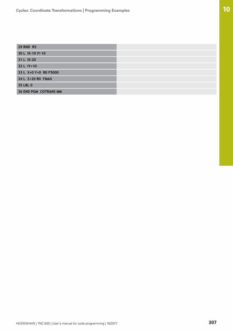
Cycles: Coordinate Transformations | Programming Examples 10
HEIDENHAIN | TNC 620 | User’s manual for cycle programming | 10/2017 307
29 RND R5
30 L IX-10 IY-10
31 L IX-20
32 L IY+10
33 L X+0 Y+0 R0 F5000
34 L Z+20 R0 FMAX
35 LBL 0
36 END PGM COTRANS MM

11Cycles: Special
Functions

Cycles: Special Functions | Fundamentals 11
310 HEIDENHAIN | TNC 620 | User’s manual for cycle programming | 10/2017
11.1 Fundamentals
OverviewThe TNC provides the following cycles for the following specialpurposes:
Soft key Cycle Page
9 DWELL TIME 311
12 Program call 312
13 Oriented spindle stop 313
32 TOLERANCE 314
225 ENGRAVING of texts 317
232 FACE MILLING 323
239 ASCERTAIN THE LOAD 328
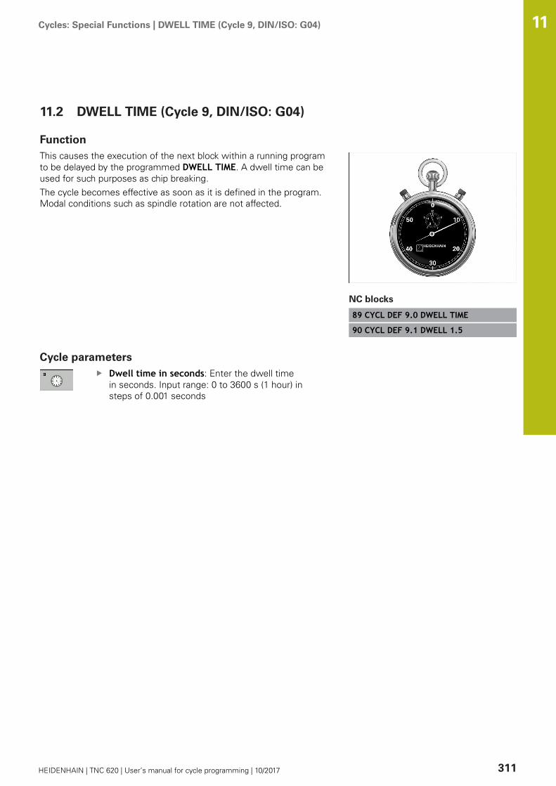
Cycles: Special Functions | DWELL TIME (Cycle 9, DIN/ISO: G04) 11
HEIDENHAIN | TNC 620 | User’s manual for cycle programming | 10/2017 311
11.2 DWELL TIME (Cycle 9, DIN/ISO: G04)
FunctionThis causes the execution of the next block within a running programto be delayed by the programmed DWELL TIME. A dwell time can beused for such purposes as chip breaking.The cycle becomes effective as soon as it is defined in the program.Modal conditions such as spindle rotation are not affected.
NC blocks
89 CYCL DEF 9.0 DWELL TIME
90 CYCL DEF 9.1 DWELL 1.5
Cycle parametersDwell time in seconds: Enter the dwell timein seconds. Input range: 0 to 3600 s (1 hour) insteps of 0.001 seconds

Cycles: Special Functions | PROGRAM CALL (Cycle 12, DIN/ISO: G39) 11
312 HEIDENHAIN | TNC 620 | User’s manual for cycle programming | 10/2017
11.3 PROGRAM CALL (Cycle 12, DIN/ISO:G39)
Cycle functionRoutines that you have programmed (such as special drilling cyclesor geometrical modules) can be written as main programs. Thesecan then be called like fixed cycles.
Please note while programming:
The program you are calling must be stored in theinternal memory of your TNC.If the program you are defining to be a cycle is locatedin the same directory as the program you are calling itfrom, you need only enter the program name.If the program you are defining to be a cycle is notlocated in the same directory as the program you arecalling it from, you must enter the complete path, forexample TNC:\KLAR35\FK1\50.H.If you want to define a DIN/ISO program to be a cycle,enter the file type .I behind the program name.As a rule, Q parameters are globally effective whencalled with Cycle 12. So please note that changes to Qparameters in the called program can also influence thecalling program.
Cycle parametersProgram name: Enter the name of the programyou want to call and, if necessary, the directory itis located in orActivate the file select dialog and select theprogram to be called via the SELECT soft key.
Call the program with:CYCL CALL (separate block) orM99 (blockwise) orM89 (executed after every positioning block)
Designate program 50 as a cycle andcall it with M99
55 CYCL DEF 12.0 PGM CALL
56 CYCL DE 12.1 PGM TNC:\KLAR35\FK1\50.H
57 L X+20 Y+50 FMAX M99

Cycles: Special Functions | SPINDLE ORIENTATION (Cycle 13, DIN/ISO: G36) 11
HEIDENHAIN | TNC 620 | User’s manual for cycle programming | 10/2017 313
11.4 SPINDLE ORIENTATION (Cycle 13, DIN/ISO: G36)
Cycle function
Machine and TNC must be specially prepared by themachine tool builder for use of this cycle.
The TNC can control the machine tool spindle and rotate it to a givenangular position.Oriented spindle stops are required for
Tool changing systems with a defined tool change positionOrientation of the transmitter/receiver window of HEIDENHAIN 3-D touch probes with infrared transmission
The angle of orientation defined in the cycle is positioned to byentering M19 or M20 (depending on the machine).If you program M19 or M20 without having defined Cycle 13, theTNC positions the machine tool spindle at an angle that has been setby the machine tool builder.More information: machine tool manual.
NC blocks
93 CYCL DEF 13.0 ORIENTATION
94 CYCL DEF 13.1 ANGLE 180
Please note while programming:
Cycle 13 is used internally for Cycles 202, 204 and 209.Please note that, if required, you must program Cycle13 again in your NC program after one of the machiningcycles mentioned above.
Cycle parametersAngle of orientation: Enter the angle referencedto the reference axis of the working plane. Inputrange: 0.0000° to 360.0000°

Cycles: Special Functions | TOLERANCE (Cycle 32, DIN/ISO: G62) 11
314 HEIDENHAIN | TNC 620 | User’s manual for cycle programming | 10/2017
11.5 TOLERANCE (Cycle 32, DIN/ISO: G62)
Cycle function
Machine and TNC must be specially prepared by themachine tool builder for use of this cycle.
With the entries in Cycle 32 you can influence the result ofHSC machining with respect to accuracy, surface definition andspeed, inasmuch as the TNC has been adapted to the machine’scharacteristics.The TNC automatically smoothens the contour between two pathelements (whether compensated or not). The tool has constantcontact with the workpiece surface and therefore reduces wear onthe machine tool. The tolerance defined in the cycle also affects thetraverse paths on circular arcs.If necessary, the TNC automatically reduces the programmed feedrate so that the program can be machined at the fastest possiblespeed without short pauses for computing time. Even if the TNCdoes not move with reduced speed, it will always comply withthe tolerance that you have defined. The larger you define thetolerance, the faster the TNC can move the axes.Smoothing the contour results in a certain amount of deviationfrom the contour. The size of this contour error (tolerance value)is set in a machine parameter by the machine manufacturer. WithCycle 32 you can change the pre-set tolerance value and selectdifferent filter settings, provided that your machine tool builder hasimplemented these features.
Influences of the geometry definition in the CAMsystemThe most important factor of influence in offline NC programcreation is the chord error S defined in the CAM system.The maximum point spacing of NC programs generated in apostprocessor (PP) is defined through the chord error. If the chorderror is less than or equal to the tolerance value T defined in Cycle32, then the TNC can smooth the contour points unless any specialmachine settings limit the programmed feed rate.You will achieve optimal smoothing if in Cycle 32 you choose atolerance value between 110-% and 200-% of the CAM chord error.

Cycles: Special Functions | TOLERANCE (Cycle 32, DIN/ISO: G62) 11
HEIDENHAIN | TNC 620 | User’s manual for cycle programming | 10/2017 315
Please note while programming:
With very small tolerance values the machine cannot cutthe contour without jerking. These jerking movementsare not caused by poor processing power in the TNC,but by the fact that, in order to machine the contourelement transitions very exactly, the TNC might have todrastically reduce the speed.Cycle 32 is DEF active which means that it becomeseffective as soon as it is defined in the part program.The TNC resets Cycle 32 if you
Redefine it and confirm the dialog question for thetolerance value with NO ENT.Select a new program with the PGM MGT key.
After you have reset Cycle 32, the TNC reactivates thetolerance that was predefined by machine parameter.In a program with millimeters set as unit of measure,the control interprets the entered tolerance value T inmillimeters. In an inch program it interprets it as inches.If you transfer a program with Cycle 32 that containsonly the cycle parameter Tolerance value T, the TNCinserts the two remaining parameters with the value 0 ifrequired.As the tolerance value increases, the diameter ofcircular movements usually decreases, unless HSCfilters are active on your machine (set by the machinetool builder).If Cycle 32 is active, the TNC shows the parametersdefined for Cycle 32 on the CYC tab of the additionalstatus display.NC programs for 5-axis simultaneous machining withspherical cutters should preferably be output for thecenter of the sphere. The NC data are then generallymore consistent. Additionally, in you can set a higherrotational axis tolerance TA (e.g. between 1° and 3°)for an even more constant feed-rate curve at the toolreference point (TCP).For NC programs for 5-axis simultaneous machiningwith toroid cutters or radius cutters where the NCoutput is for the south pole of the sphere, choose alower rotational axis tolerance. 0.1° is a typical value.However, the maximum permissible contour damage isthe decisive factor for the rotational axis tolerance. Thiscontour damage depends on the possible tool tilting,tool radius and contact depth of the tool.With 5-axis gear hobbing with an end mill you cancalculate the maximum possible contour damage Tdirectly from the cutter contact length L and permissiblecontour tolerance TA: T ~ K x L x TA K = 0.0175 [1/°] Example: L = 10 mm, TA = 0.1°: T = 0.0175 mm

Cycles: Special Functions | TOLERANCE (Cycle 32, DIN/ISO: G62) 11
316 HEIDENHAIN | TNC 620 | User’s manual for cycle programming | 10/2017
Cycle parametersTolerance value T: Permissible contour deviationin mm (or inches with inch programming). Inputrange 0.0000 to 10.0000>0: With an input value > 0 the TNC uses themaximum permissible deviation0 you entered: If 0 is entered or if duringprogramming you press the NO ENT key, theTNC uses a value configured by the machine toolbuilderHSC MODE, Finishing=0, Roughing=1: Activatefilter:
Input value 0: Milling with increased contouraccuracy. The TNC uses internally definedfinishing filter settingsInput value 1: Milling at an increased feedrate. The TNC uses internally defined roughingfilter settings
Tolerance for rotary axes TA: Permissiblepositioning error of rotary axes in degrees whenM128 is active (FUNCTION TCPM). The TNCalways reduces the feed rate in such a way that—if more than one axis is traversed—the slowestaxis moves at its maximum feed rate. Rotaryaxes are usually much slower than linear axes.You can significantly reduce the machining timefor programs for more than one axis by enteringa large tolerance value (e.g. 10°), since the TNCdoes not always have to precisely move therotary axis to the given nominal position. The toolorientation (position of the rotary axis with respectto the workpiece surface) will be adjusted. Theposition at Tool Center Point (TCP) is automaticallycorrected. With a ball-nose cutter for example,measured in the center and programmed to themidpoint path, this has no negative effects on thecontour. Input range 0.0000 to 10.0000>0: With an input value > 0 the TNC uses themaximum permissible deviation0 you entered: If 0 is entered or if duringprogramming you press the NO ENT key, theTNC uses a value configured by the machine toolbuilder
NC blocks
95 CYCL DEF 32.0 TOLERANCE
96 CYCL DEF 32.1 T0.05
97 CYCL DEF 32.2 HSC-MODE:1 TA5
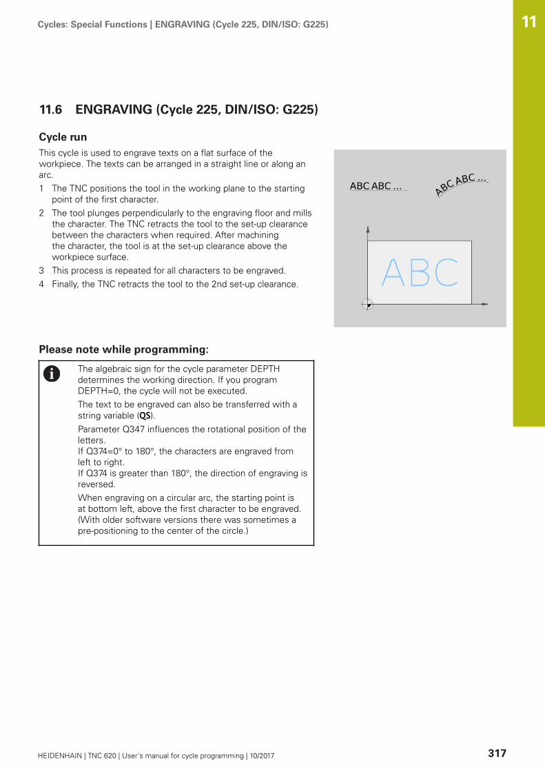
Cycles: Special Functions | ENGRAVING (Cycle 225, DIN/ISO: G225) 11
HEIDENHAIN | TNC 620 | User’s manual for cycle programming | 10/2017 317
11.6 ENGRAVING (Cycle 225, DIN/ISO: G225)
Cycle runThis cycle is used to engrave texts on a flat surface of theworkpiece. The texts can be arranged in a straight line or along anarc.1 The TNC positions the tool in the working plane to the starting
point of the first character.2 The tool plunges perpendicularly to the engraving floor and mills
the character. The TNC retracts the tool to the set-up clearancebetween the characters when required. After machiningthe character, the tool is at the set-up clearance above theworkpiece surface.
3 This process is repeated for all characters to be engraved.4 Finally, the TNC retracts the tool to the 2nd set-up clearance.
Please note while programming:
The algebraic sign for the cycle parameter DEPTHdetermines the working direction. If you programDEPTH=0, the cycle will not be executed.The text to be engraved can also be transferred with astring variable (QS).Parameter Q347 influences the rotational position of theletters. If Q374=0° to 180°, the characters are engraved fromleft to right.If Q374 is greater than 180°, the direction of engraving isreversed.When engraving on a circular arc, the starting point isat bottom left, above the first character to be engraved.(With older software versions there was sometimes apre-positioning to the center of the circle.)
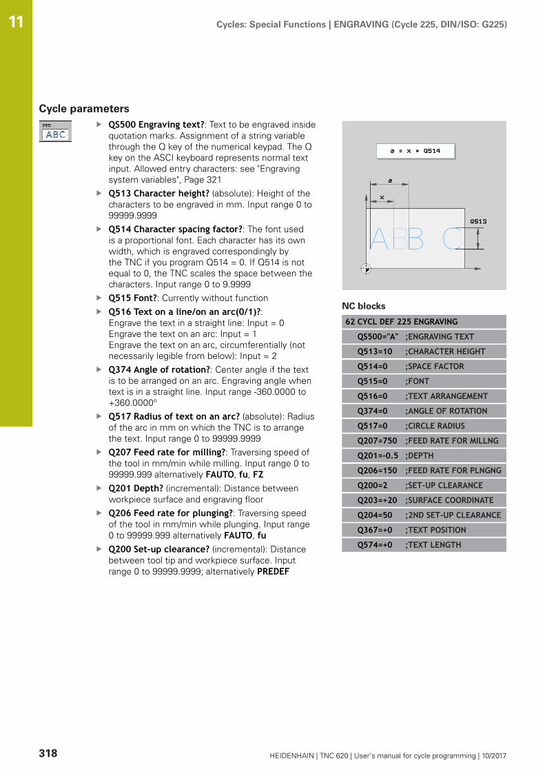
Cycles: Special Functions | ENGRAVING (Cycle 225, DIN/ISO: G225) 11
318 HEIDENHAIN | TNC 620 | User’s manual for cycle programming | 10/2017
Cycle parametersQS500 Engraving text?: Text to be engraved insidequotation marks. Assignment of a string variablethrough the Q key of the numerical keypad. The Qkey on the ASCI keyboard represents normal textinput. Allowed entry characters: see "Engravingsystem variables", Page 321Q513 Character height? (absolute): Height of thecharacters to be engraved in mm. Input range 0 to99999.9999Q514 Character spacing factor?: The font usedis a proportional font. Each character has its ownwidth, which is engraved correspondingly bythe TNC if you program Q514 = 0. If Q514 is notequal to 0, the TNC scales the space between thecharacters. Input range 0 to 9.9999Q515 Font?: Currently without functionQ516 Text on a line/on an arc(0/1)?: Engrave the text in a straight line: Input = 0 Engrave the text on an arc: Input = 1Engrave the text on an arc, circumferentially (notnecessarily legible from below): Input = 2Q374 Angle of rotation?: Center angle if the textis to be arranged on an arc. Engraving angle whentext is in a straight line. Input range -360.0000 to+360.0000°Q517 Radius of text on an arc? (absolute): Radiusof the arc in mm on which the TNC is to arrangethe text. Input range 0 to 99999.9999Q207 Feed rate for milling?: Traversing speed ofthe tool in mm/min while milling. Input range 0 to99999.999 alternatively FAUTO, fu, FZQ201 Depth? (incremental): Distance betweenworkpiece surface and engraving floorQ206 Feed rate for plunging?: Traversing speedof the tool in mm/min while plunging. Input range0 to 99999.999 alternatively FAUTO, fuQ200 Set-up clearance? (incremental): Distancebetween tool tip and workpiece surface. Inputrange 0 to 99999.9999; alternatively PREDEF
NC blocks
62 CYCL DEF 225 ENGRAVING
QS500="A" ;ENGRAVING TEXT
Q513=10 ;CHARACTER HEIGHT
Q514=0 ;SPACE FACTOR
Q515=0 ;FONT
Q516=0 ;TEXT ARRANGEMENT
Q374=0 ;ANGLE OF ROTATION
Q517=0 ;CIRCLE RADIUS
Q207=750 ;FEED RATE FOR MILLNG
Q201=-0.5 ;DEPTH
Q206=150 ;FEED RATE FOR PLNGNG
Q200=2 ;SET-UP CLEARANCE
Q203=+20 ;SURFACE COORDINATE
Q204=50 ;2ND SET-UP CLEARANCE
Q367=+0 ;TEXT POSITION
Q574=+0 ;TEXT LENGTH

Cycles: Special Functions | ENGRAVING (Cycle 225, DIN/ISO: G225) 11
HEIDENHAIN | TNC 620 | User’s manual for cycle programming | 10/2017 319
Q203 Workpiece surface coordinate? (absolute):Coordinate of the workpiece surface. Input range-99999.9999 to 99999.9999Q204 2nd set-up clearance? (incremental):Coordinate in the spindle axis at which no collisionbetween tool and workpiece (fixtures) can occur.Input range 0 to 99999.9999; alternatively PREDEFQ574 Maximum text length? (mm/inch): Enter themaximum text length here. The TNC also takesinto account parameter Q513 Character height. IfQ513=0, the TNC engraves the text over exactlythe length indicated in parameter Q574. Thecharacter height is scaled correspondingly. If Q513is greater than zero, the TNC checks whetherthe actual text length exceeds the maximum textlength entered in Q574, If that is the case, the TNCdisplays an error message.Q367 Reference for text position (0-6)? Enterhere the reference for the position of the text.Depending on whether the text is engraved onan arc or a straight line (parameter Q516), thefollowing entries are possible:If engraved on an arc, the text position refers tothe following point:0 = Center of the circle1 = Bottom left2 = Bottom center3 = Bottom right4 = Top right5 = Top center6 = Top leftIf engraved on a straight line, the text positionrefers to the following point:0 = Bottom left1 = Bottom left2 = Bottom center3 = Bottom right4 = Top right5 = Top center6 = Top left

Cycles: Special Functions | ENGRAVING (Cycle 225, DIN/ISO: G225) 11
320 HEIDENHAIN | TNC 620 | User’s manual for cycle programming | 10/2017
Allowed engraving charactersThe following special characters are allowed in addition tolowercase letters, uppercase letters and numbers: ! # $ % & ‘ ( ) * + , - . / : ; < = > ? @ [ \ ] _ ß CE
The TNC uses the special characters % and \ for specialfunctions. These characters must be indicated twice inthe text to be engraved (e.g. %%) if you want to engravethem.
When engraving German umlauts, ß, ø, @ or the CE character,enter the character % before the character to be engraved:
Algebraic sign Input
ä %ae
ö %oe
ü %ue
Ä %AE
Ö %OE
Ü %UE
ß %ss
ø %D
@ %at
CE %CE
Characters that cannot be printedApart from text, you can also define certain non-printablecharacters for formatting purposes. Enter the special character \before the non-printable characters.The following formatting possibilities are available:
Character Input
Line break \n
Horizontal tab (the tab width is permanently set to 8characters)
\t
Vertical tab (the tab width is permanently set to oneline)
\v

Cycles: Special Functions | ENGRAVING (Cycle 225, DIN/ISO: G225) 11
HEIDENHAIN | TNC 620 | User’s manual for cycle programming | 10/2017 321
Engraving system variablesIn addition to the standard characters, you can engrave thecontents of certain system variables. Enter % before the systemvariable.You can also engrave the current date or time. Enter %time<x>.<x> defines the format, e.g. 08 for DD.MM.YYYY. (Identical to theSYSSTR ID321 function)
Keep in mind that you must enter a leading 0 whenentering the date formats 1 to 9, e.g. time08.
Character Input
DD.MM.YYYY hh:mm:ss %time00
D.MM.YYYY h:mm:ss %time01
D.MM.YYYY h:mm %time02
D.MM.YY h:mm %time03
YYYY-MM-DD hh:mm:ss %time04
YYYY-MM-DD hh:mm %time05
YYYY-MM-DD h:mm %time06
YY-MM-DD h:mm %time07
DD.MM.YYYY %time08
D.MM.YYYY %time09
D.MM.YY %time10
YYYY-MM-DD %time11
YY-MM-DD %time12
hh:mm:ss %time13
h:mm:ss %time14
h:mm %time15

Cycles: Special Functions | ENGRAVING (Cycle 225, DIN/ISO: G225) 11
322 HEIDENHAIN | TNC 620 | User’s manual for cycle programming | 10/2017
Engraving the counter readingYou can engrave the current counter reading found in the MODmenu with Cycle 225.For this purpose program Cycle 225 as usual and enter e.g. thefollowing for the text to be engraved: %count2The number after %count specifies how many positions the TNCengraves. A maximum of nine positions are possible.Example: If you program %count9 in the cycle with a momentarycounter reading of 3, the TNC engraves: 000000003
NOTICEIn Test Run operating mode the momentary counter readingis always simulated with the number 0, independent of thecounter reading actually entered in the MOD menu.
The TNC does not consider the active counter reading in TestRun operating mode. The reading cannot be switched higherwith a repeated test of the NC program and cannot be outputwith Cycle 225. This is why a counter reading of zero is alwayssimulated in Test Run operating mode.
In Program Run, Full Sequence and Program Run, SingleBlock operating modes the active counter reading is takeninto consideration.If you switch over the screen layout in these operatingmodes, e.g. to the PROGRAM + GRAPHICS view, thecurrently engraved counter reading is shown in the motionsimulation
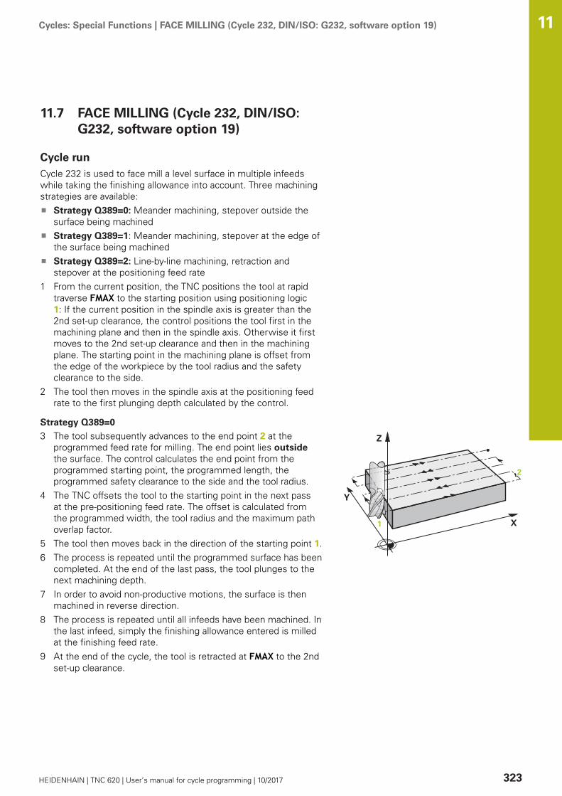
Cycles: Special Functions | FACE MILLING (Cycle 232, DIN/ISO: G232, software option 19) 11
HEIDENHAIN | TNC 620 | User’s manual for cycle programming | 10/2017 323
11.7 FACE MILLING (Cycle 232, DIN/ISO:G232, software option 19)
Cycle runCycle 232 is used to face mill a level surface in multiple infeedswhile taking the finishing allowance into account. Three machiningstrategies are available:
Strategy Q389=0: Meander machining, stepover outside thesurface being machinedStrategy Q389=1: Meander machining, stepover at the edge ofthe surface being machinedStrategy Q389=2: Line-by-line machining, retraction andstepover at the positioning feed rate
1 From the current position, the TNC positions the tool at rapidtraverse FMAX to the starting position using positioning logic1: If the current position in the spindle axis is greater than the2nd set-up clearance, the control positions the tool first in themachining plane and then in the spindle axis. Otherwise it firstmoves to the 2nd set-up clearance and then in the machiningplane. The starting point in the machining plane is offset fromthe edge of the workpiece by the tool radius and the safetyclearance to the side.
2 The tool then moves in the spindle axis at the positioning feedrate to the first plunging depth calculated by the control.
Strategy Q389=0
3 The tool subsequently advances to the end point 2 at theprogrammed feed rate for milling. The end point lies outsidethe surface. The control calculates the end point from theprogrammed starting point, the programmed length, theprogrammed safety clearance to the side and the tool radius.
4 The TNC offsets the tool to the starting point in the next passat the pre-positioning feed rate. The offset is calculated fromthe programmed width, the tool radius and the maximum pathoverlap factor.
5 The tool then moves back in the direction of the starting point 1.6 The process is repeated until the programmed surface has been
completed. At the end of the last pass, the tool plunges to thenext machining depth.
7 In order to avoid non-productive motions, the surface is thenmachined in reverse direction.
8 The process is repeated until all infeeds have been machined. Inthe last infeed, simply the finishing allowance entered is milledat the finishing feed rate.
9 At the end of the cycle, the tool is retracted at FMAX to the 2ndset-up clearance.
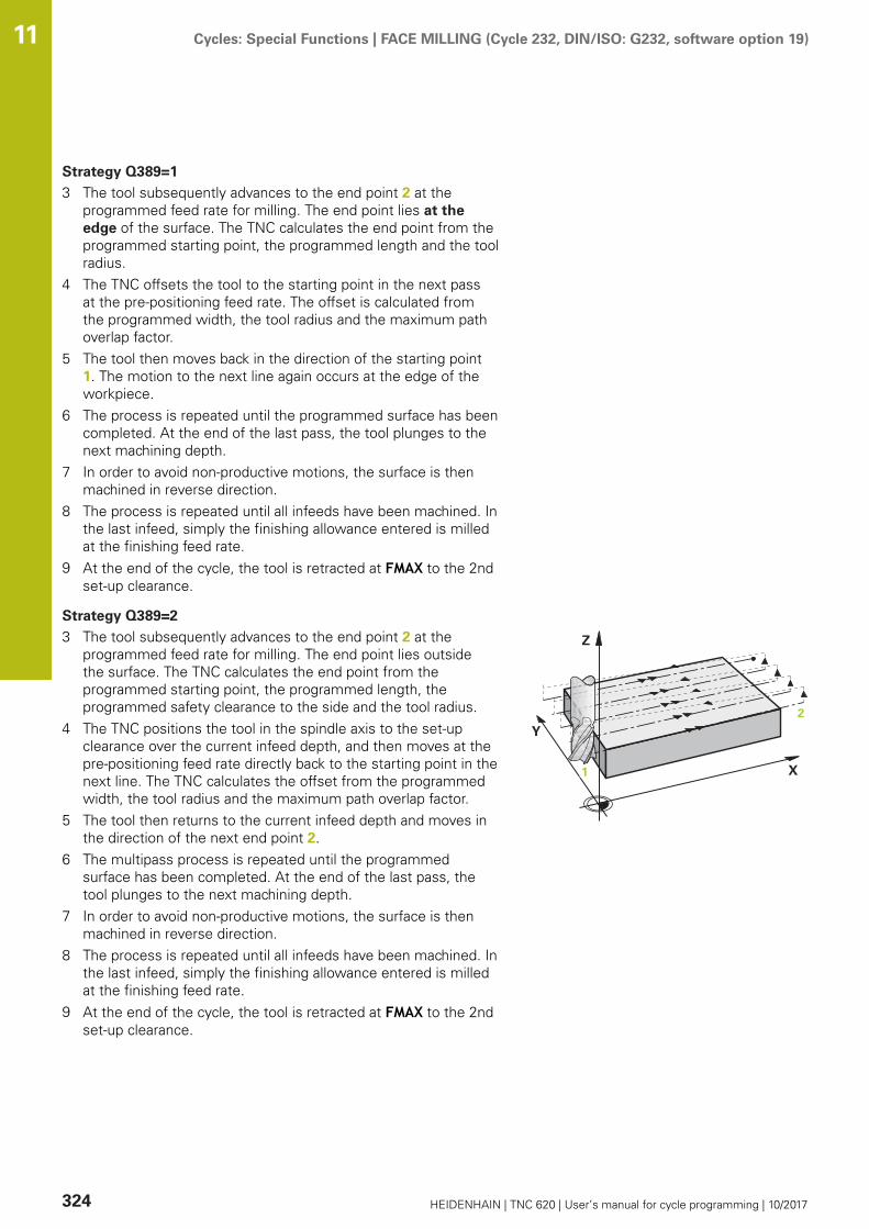
Cycles: Special Functions | FACE MILLING (Cycle 232, DIN/ISO: G232, software option 19) 11
324 HEIDENHAIN | TNC 620 | User’s manual for cycle programming | 10/2017
Strategy Q389=1
3 The tool subsequently advances to the end point 2 at theprogrammed feed rate for milling. The end point lies at theedge of the surface. The TNC calculates the end point from theprogrammed starting point, the programmed length and the toolradius.
4 The TNC offsets the tool to the starting point in the next passat the pre-positioning feed rate. The offset is calculated fromthe programmed width, the tool radius and the maximum pathoverlap factor.
5 The tool then moves back in the direction of the starting point1. The motion to the next line again occurs at the edge of theworkpiece.
6 The process is repeated until the programmed surface has beencompleted. At the end of the last pass, the tool plunges to thenext machining depth.
7 In order to avoid non-productive motions, the surface is thenmachined in reverse direction.
8 The process is repeated until all infeeds have been machined. Inthe last infeed, simply the finishing allowance entered is milledat the finishing feed rate.
9 At the end of the cycle, the tool is retracted at FMAX to the 2ndset-up clearance.
Strategy Q389=2
3 The tool subsequently advances to the end point 2 at theprogrammed feed rate for milling. The end point lies outsidethe surface. The TNC calculates the end point from theprogrammed starting point, the programmed length, theprogrammed safety clearance to the side and the tool radius.
4 The TNC positions the tool in the spindle axis to the set-upclearance over the current infeed depth, and then moves at thepre-positioning feed rate directly back to the starting point in thenext line. The TNC calculates the offset from the programmedwidth, the tool radius and the maximum path overlap factor.
5 The tool then returns to the current infeed depth and moves inthe direction of the next end point 2.
6 The multipass process is repeated until the programmedsurface has been completed. At the end of the last pass, thetool plunges to the next machining depth.
7 In order to avoid non-productive motions, the surface is thenmachined in reverse direction.
8 The process is repeated until all infeeds have been machined. Inthe last infeed, simply the finishing allowance entered is milledat the finishing feed rate.
9 At the end of the cycle, the tool is retracted at FMAX to the 2ndset-up clearance.

Cycles: Special Functions | FACE MILLING (Cycle 232, DIN/ISO: G232, software option 19) 11
HEIDENHAIN | TNC 620 | User’s manual for cycle programming | 10/2017 325
Please note while programming:
Enter the Q204 2ND SET-UP CLEARANCE so that nocollision with the workpiece or the fixtures can occur.If Q227 STARTNG PNT 3RD AXIS and Q386 END POINT3RD AXIS are entered as equal values, the TNC will notcarry out the cycle (depth=0 programmed).Program Q227 greater than Q386. Otherwise, the TNCwill display an error message.

Cycles: Special Functions | FACE MILLING (Cycle 232, DIN/ISO: G232, software option 19) 11
326 HEIDENHAIN | TNC 620 | User’s manual for cycle programming | 10/2017
Cycle parametersQ389 Machining strategy (0/1/2)?: Determinehow the TNC should machine the surface:0: Meander machining, stepover at the positioningfeed rate outside the surface being machined1: Meander machining, stepover at the feedrate for milling at the edge of the surface beingmachined2: Line-by-line machining, retraction and stepoverat the positioning feed rateQ225 Starting point in 1st axis? (absolute):Starting point coordinate of the surface to bemachined in the reference axis of the workingplane. Input range -99999.9999 to 99999.9999Q226 Starting point in 2nd axis? (absolute):Starting point coordinate of the surface to bemachined in the minor axis of the working plane.Input range -99999.9999 to 99999.9999Q227 Starting point in 3rd axis? (absolute):Coordinate of the workpiece surface used tocalculate the infeeds. Input range -99999.9999 to99999.9999Q386 End point in 3rd axis? (absolute):Coordinate in the spindle axis on which the surfaceis to be face-milled. Input range -99999.9999 to99999.9999Q218 First side length? (incremental): Lengthof the surface to be machined in the referenceaxis of the working plane. Use the algebraic signto specify the direction of the first milling path inreference to the starting point in the 1st axis.Input range -99999.9999 to 99999.9999Q219 Second side length? (incremental): Lengthof the surface to be machined in the minor axisof the working plane. Use the algebraic signto specify the direction of the first transverseapproach in reference to the STARTNG PNT 2NDAXIS. Input range -99999.9999 to 99999.9999Q202 Maximum plunging depth? (incremental):Maximum infeed per cut. The TNC calculates theactual plunging depth from the difference betweenthe end point and starting point of the tool axis(taking the finishing allowance into account), sothat uniform plunging depths are used each time.Input range 0 to 99999.9999Q369 Finishing allowance for floor?(incremental): Distance used for the last infeed.Input range 0 to 99999.9999

Cycles: Special Functions | FACE MILLING (Cycle 232, DIN/ISO: G232, software option 19) 11
HEIDENHAIN | TNC 620 | User’s manual for cycle programming | 10/2017 327
Q370 Max. path overlap factor?: Maximumstepover factor k. The TNC calculates the actualstepover from the second side length (Q219) andthe tool radius so that a constant stepover is usedfor machining. If you have entered a radius R2in the tool table (e.g. tooth radius when using aface-milling cutter), the TNC reduces the stepoveraccordingly. Input range 0.1 to 1.9999Q207 Feed rate for milling?: Traversing speed ofthe tool in mm/min while milling. Input range 0 to99999.999 alternatively FAUTO, fu, FZQ385 Finishing feed rate?: Traversing speed ofthe tool in mm/min while milling the last infeed.Input range 0 to 99999.9999, alternatively FAUTO,fu, FZQ253 Feed rate for pre-positioning?: Traversingspeed of the tool in mm/min when approachingthe starting position and when moving to the nextpass. If you are moving the tool transversely tothe material (Q389=1), the TNC moves the toolat the feed rate for milling Q207. Input range 0 to99999.9999, alternatively fmax, FAUTOQ200 Set-up clearance? (incremental): Distancebetween tool tip and the starting position in thetool axis. If you are milling with machining strategyQ389=2, the TNC moves the tool at the set-upclearance over the current plunging depth to thestarting point of the next pass. Input range 0 to99999.9999Q357 Safety clearance to the side? (incremental)Parameter Q357 has an influence on the followingsituations: Approach the first plunging depth: Q357 isthe safety clearance of the tool to the side of theworkpieceRoughing with milling strategies Q389=0-3: Thesurface in Q350 MILLING DIRECTION is increasedby the value from Q357, provided that no limitationis set in this directionSide finishing: The paths are extended by Q357in Q350 MILLING DIRECTIONInput range 0 to 99999.9999Q204 2nd set-up clearance? (incremental):Coordinate in the spindle axis at which no collisionbetween tool and workpiece (fixtures) can occur.Input range 0 to 99999.9999; alternatively PREDEF
NC blocks
71 CYCL DEF 232 FACE MILLING
Q389=2 ;STRATEGY
Q225=+10 ;STARTNG PNT 1ST AXIS
Q226=+12 ;STARTNG PNT 2ND AXIS
Q227=+2.5 ;STARTNG PNT 3RD AXIS
Q386=-3 ;END POINT 3RD AXIS
Q218=150 ;FIRST SIDE LENGTH
Q219=75 ;2ND SIDE LENGTH
Q202=2 ;MAX. PLUNGING DEPTH
Q369=0.5 ;ALLOWANCE FOR FLOOR
Q370=1 ;MAX. OVERLAP
Q207=500 ;FEED RATE FOR MILLNG
Q385=800 ;FINISHING FEED RATE
Q253=2000 ;F PRE-POSITIONING
Q200=2 ;SET-UP CLEARANCE
Q357=2 ;CLEARANCE TO SIDE
Q204=2 ;2ND SET-UP CLEARANCE

Cycles: Special Functions | ASCERTAIN THE LOAD (Cycle 239, DIN/ISO: G239, software option 143) 11
328 HEIDENHAIN | TNC 620 | User’s manual for cycle programming | 10/2017
11.8 ASCERTAIN THE LOAD (Cycle 239, DIN/ISO: G239, software option 143)
Cycle runThe dynamic behavior of your machine may vary with differentworkpiece weights acting on the machine table. A change in theload has an influence on the friction forces, acceleration, holdingtorque and stick-slip friction of table axes. With option 143 LAC(Load Adaptive Control) and Cycle 239 ASCERTAIN THE LOAD, thecontrol can automatically determine and adjust the current loadmass, the current frictional forces and maximum axis acceleration,and reset the feedforward and controller parameters. In this way,you can optimally react to major load changes. The TNC performsa weighing procedure to ascertain the weight acting on the axes.The axes traverse a specific path with this weighing procedure—the machine tool builder defines the precise movements. Beforeweighing, the axes are moved to a position, if required, wherethere is no danger of collision during the weighing procedure. Thissafe position is defined by the machine tool builder.In addition to adjusting the control parameters, with LAC themaximum acceleration is also adjusted in accordance with theweight. This enables the dynamics to be accordingly increased withlow load to increase productivity.Parameter Q570 = 0
1 There is no physical movement of the axes.2 The TNC resets the LAC.3 The TNC activates feedforward parameters and, if applicable,
controller parameters that ensure a safe movement of the axesconcerned, regardless of the load condition—the parametersset with Q570=0 are independent of the current load.
4 These parameters can be useful during the setup procedure orafter the completion of an NC program.
Parameter Q570 = 1
1 The TNC performs a weighing procedure in which it moves oneor more axes. Which axes are moved depends on the setup ofthe machine and on the drives of the axes.
2 The scope of axis movement is defined by the machine toolbuilder.
3 The feedforward and controller parameters determined by theTNC depend on the current load.
4 The TNC activates the parameters determined.

Cycles: Special Functions | ASCERTAIN THE LOAD (Cycle 239, DIN/ISO: G239, software option 143) 11
HEIDENHAIN | TNC 620 | User’s manual for cycle programming | 10/2017 329
Please note while programming:
The machine must be prepared by the machine toolbuilder for this cycle.Cycle 239 can only be used with option 143 LAC (LoadAdaptive Control).
NOTICEDanger of collision!
The cycle can execute extensive movements in several axes atrapid traverse!
Ask your machine manufacturer about the type and extent ofCycle 239 before using itBefore cycle start, the TNC might move to a safe position;this position is defined by the machine tool builderSet the potentiometer for feed-rate and rapid-traverseoverride to at least 50 % to ensure a correct ascertainment ofthe load
Cycle 239 becomes effective immediately afterdefinition.If you are using the mid-program startup function andthe TNC skips Cycle 239 in the block scan, the TNCwill ignore this cycle—no weighing procedure will beperformed.Cycle 239 supports the determination of the loadon synchronized axes, provided they have only onecommon position measuring device (torque masterslave).
Cycle parametersQ570 Load (0 = Delete/1 = Ascertain)?: Specifywhether the TNC should perform an LAC (Loadadaptive control) weighing run, or whetherthe most recently ascertained load-dependentfeedforward and controller parameters should bereset:0: Reset LAC; the values most recentlyascertained by the TNC are reset, and the TNCuses load-independent feedforward and controllerparameters1: Perform a weighing run; the TNC movesthe axes and thus ascertains the feedforwardand controller parameters depending on thecurrent load. The values ascertained are activatedimmediately
NC blocks
62 CYCL DEF 239 ASCERTAIN THE LOAD
Q570=+0 ;LOAD ASCERTATION
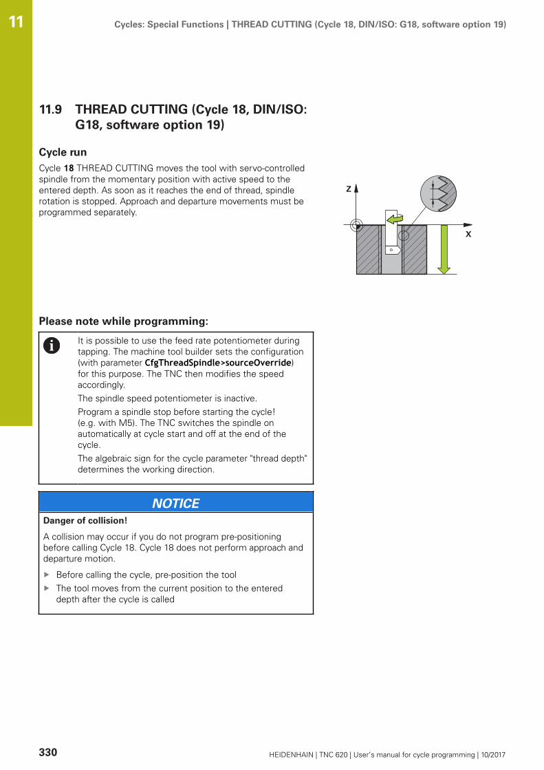
Cycles: Special Functions | THREAD CUTTING (Cycle 18, DIN/ISO: G18, software option 19) 11
330 HEIDENHAIN | TNC 620 | User’s manual for cycle programming | 10/2017
11.9 THREAD CUTTING (Cycle 18, DIN/ISO:G18, software option 19)
Cycle runCycle 18 THREAD CUTTING moves the tool with servo-controlledspindle from the momentary position with active speed to theentered depth. As soon as it reaches the end of thread, spindlerotation is stopped. Approach and departure movements must beprogrammed separately.
Please note while programming:
It is possible to use the feed rate potentiometer duringtapping. The machine tool builder sets the configuration(with parameter CfgThreadSpindle>sourceOverride)for this purpose. The TNC then modifies the speedaccordingly.The spindle speed potentiometer is inactive.Program a spindle stop before starting the cycle!(e.g. with M5). The TNC switches the spindle onautomatically at cycle start and off at the end of thecycle.The algebraic sign for the cycle parameter "thread depth"determines the working direction.
NOTICEDanger of collision!
A collision may occur if you do not program pre-positioningbefore calling Cycle 18. Cycle 18 does not perform approach anddeparture motion.
Before calling the cycle, pre-position the toolThe tool moves from the current position to the entereddepth after the cycle is called

Cycles: Special Functions | THREAD CUTTING (Cycle 18, DIN/ISO: G18, software option 19) 11
HEIDENHAIN | TNC 620 | User’s manual for cycle programming | 10/2017 331
NOTICEDanger of collision!
If the spindle was switched on before calling the cycle, Cycle 18switches the spindle off and the cycle works with a stationaryspindle! Cycle 18 switches the spindle on again at the end if itwas switched on before cycle start.
Program a spindle stop before starting the cycle! (e.g. withM5)After Cycle 18 has finished the spindle condition before cyclestart is restored. If the spindle was switched off before cyclestart, the TNC switches it off again at the end of Cycle 18.
Cycle parametersBoring depth (incremental): Enter the thread depthbased on the current position Input range: -99999to +99999Thread pitch: Enter the pitch of the thread. Thealgebraic sign entered here differentiates betweenright-hand and left-hand threads:+ = right-hand thread (M3 with negative holedepth)- = left-hand thread (M4 with negative hole depth)
NC blocks
25 CYCL DEF 18.0 THREAD CUTTING
26 CYCL DEF 18.1 DEPTH = -20
27 CYCL DEF 18.2 PITCH = +1


12Using Touch Probe
Cycles
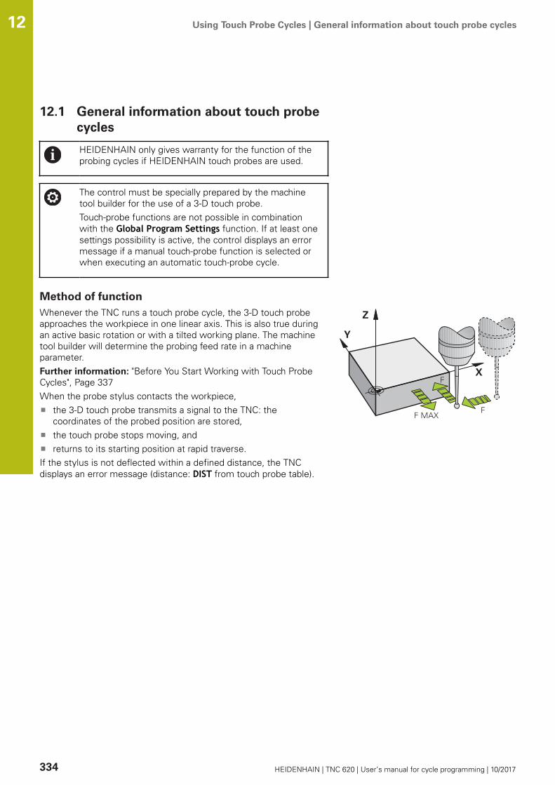
Using Touch Probe Cycles | General information about touch probe cycles 12
334 HEIDENHAIN | TNC 620 | User’s manual for cycle programming | 10/2017
12.1 General information about touch probecycles
HEIDENHAIN only gives warranty for the function of theprobing cycles if HEIDENHAIN touch probes are used.
The control must be specially prepared by the machinetool builder for the use of a 3-D touch probe.Touch-probe functions are not possible in combinationwith the Global Program Settings function. If at least onesettings possibility is active, the control displays an errormessage if a manual touch-probe function is selected orwhen executing an automatic touch-probe cycle.
Method of functionWhenever the TNC runs a touch probe cycle, the 3-D touch probeapproaches the workpiece in one linear axis. This is also true duringan active basic rotation or with a tilted working plane. The machinetool builder will determine the probing feed rate in a machineparameter.Further information: "Before You Start Working with Touch ProbeCycles", Page 337When the probe stylus contacts the workpiece,
the 3-D touch probe transmits a signal to the TNC: thecoordinates of the probed position are stored,the touch probe stops moving, andreturns to its starting position at rapid traverse.
If the stylus is not deflected within a defined distance, the TNCdisplays an error message (distance: DIST from touch probe table).
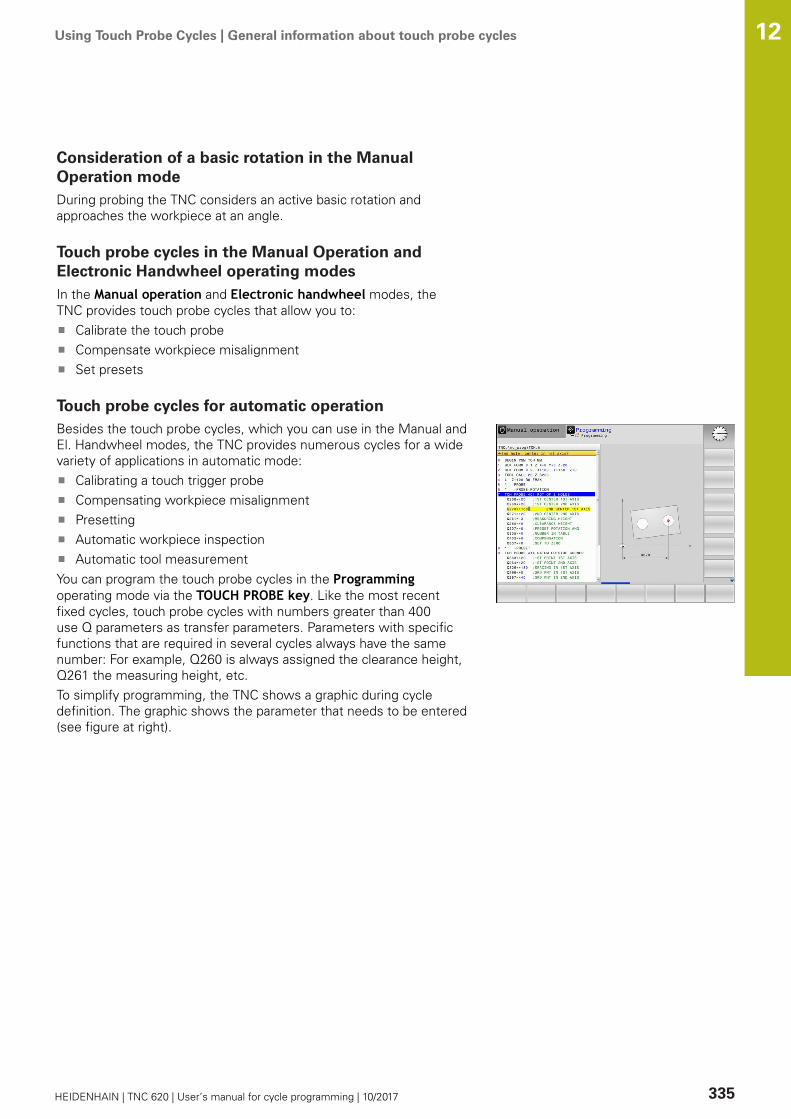
Using Touch Probe Cycles | General information about touch probe cycles 12
HEIDENHAIN | TNC 620 | User’s manual for cycle programming | 10/2017 335
Consideration of a basic rotation in the ManualOperation modeDuring probing the TNC considers an active basic rotation andapproaches the workpiece at an angle.
Touch probe cycles in the Manual Operation andElectronic Handwheel operating modesIn the Manual operation and Electronic handwheel modes, theTNC provides touch probe cycles that allow you to:
Calibrate the touch probeCompensate workpiece misalignmentSet presets
Touch probe cycles for automatic operationBesides the touch probe cycles, which you can use in the Manual andEl. Handwheel modes, the TNC provides numerous cycles for a widevariety of applications in automatic mode:
Calibrating a touch trigger probeCompensating workpiece misalignmentPresettingAutomatic workpiece inspectionAutomatic tool measurement
You can program the touch probe cycles in the Programmingoperating mode via the TOUCH PROBE key. Like the most recentfixed cycles, touch probe cycles with numbers greater than 400use Q parameters as transfer parameters. Parameters with specificfunctions that are required in several cycles always have the samenumber: For example, Q260 is always assigned the clearance height,Q261 the measuring height, etc.To simplify programming, the TNC shows a graphic during cycledefinition. The graphic shows the parameter that needs to be entered(see figure at right).

Using Touch Probe Cycles | General information about touch probe cycles 12
336 HEIDENHAIN | TNC 620 | User’s manual for cycle programming | 10/2017
Defining the touch probe cycle in the Programming mode ofoperation
The soft-key row shows all available touch probefunctions divided into groups.
Select the desired probe cycle group, for examplepresetting. Cycles for automatic tool measurementare available only if your machine has beenprepared for them.Select a cycle, e.g. presetting at pocket center.The TNC initiates the programming dialog and asksfor all required input values. At the same time agraphic of the input parameters is displayed in theright screen window. The parameter that is askedfor in the dialog prompt is highlighted.Enter all parameters requested by the TNC andconclude each entry with the ENT key.The TNC ends the dialog when all required datahas been entered
Soft key Group of measuring cycles Page
Cycles for automatic measurement andcompensation of workpiece misalignment
344
Cycles for automatic workpiece presetting 368
Cycles for automatic workpiece inspection 426
Special cycles 470
Calibrate TS 470
Kinematics 490
Cycles for automatic tool measurement(enabled by the machine tool builder)
522
NC blocks
5 TCH PROBE 410 PRESET INSIDERECTAN.
Q321=+50 ;CENTER IN 1ST AXIS
Q322=+50 ;CENTER IN 2ND AXIS
Q323=60 ;FIRST SIDE LENGTH
Q324=20 ;2ND SIDE LENGTH
Q261=-5 ;MEASURING HEIGHT
Q320=0 ;SET-UP CLEARANCE
Q260=+20 ;CLEARANCE HEIGHT
Q301=0 ;MOVE TO CLEARANCE
Q305=10 ;NUMBER IN TABLE
Q331=+0 ;PRESET
Q332=+0 ;PRESET
Q303=+1 ;MEAS. VALUE TRANSFER
Q381=1 ;PROBE IN TS AXIS
Q382=+85 ;1ST CO. FOR TS AXIS
Q383=+50 ;2ND CO. FOR TS AXIS
Q384=+0 ;3RD CO. FOR TS AXIS
Q333=+0 ;PRESET
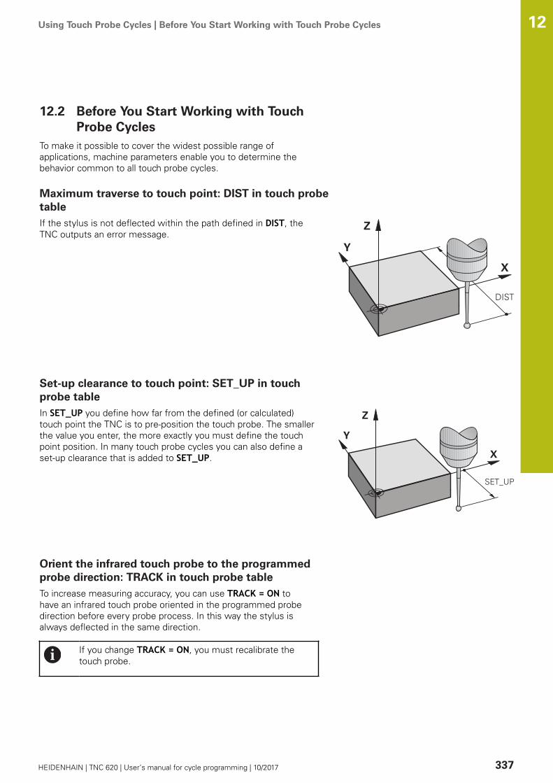
Using Touch Probe Cycles | Before You Start Working with Touch Probe Cycles 12
HEIDENHAIN | TNC 620 | User’s manual for cycle programming | 10/2017 337
12.2 Before You Start Working with TouchProbe Cycles
To make it possible to cover the widest possible range ofapplications, machine parameters enable you to determine thebehavior common to all touch probe cycles.
Maximum traverse to touch point: DIST in touch probetableIf the stylus is not deflected within the path defined in DIST, theTNC outputs an error message.
Set-up clearance to touch point: SET_UP in touchprobe tableIn SET_UP you define how far from the defined (or calculated)touch point the TNC is to pre-position the touch probe. The smallerthe value you enter, the more exactly you must define the touchpoint position. In many touch probe cycles you can also define aset-up clearance that is added to SET_UP.
Orient the infrared touch probe to the programmedprobe direction: TRACK in touch probe tableTo increase measuring accuracy, you can use TRACK = ON tohave an infrared touch probe oriented in the programmed probedirection before every probe process. In this way the stylus isalways deflected in the same direction.
If you change TRACK = ON, you must recalibrate thetouch probe.

Using Touch Probe Cycles | Before You Start Working with Touch Probe Cycles 12
338 HEIDENHAIN | TNC 620 | User’s manual for cycle programming | 10/2017
Touch trigger probe, probing feed rate: F in touchprobe tableIn F you define the feed rate at which the TNC is to probe theworkpiece.F can never exceed the value set in machine parametermaxTouchFeed (No. 122602).The feed rate potentiometer may be effective with touch probecycles. The machine tool builder defines the required settings.(the parameter overrideForMeasure (No. 122604) must beappropriately configured.)
Touch trigger probe, rapid traverse for positioning:FMAXIn FMAX you define the feed rate at which the TNC pre-positionsthe touch probe, or positions it between measuring points.
Touch trigger probe, rapid traverse for positioning:F_PREPOS in touch probe tableIn F_PREPOS you define whether the TNC is to position the touchprobe at the feed rate defined in FMAX or at rapid traverse.
Input value = FMAX_PROBE: Position at feed rate from FMAXInput value = FMAX_MACHINE: Pre-position at rapid traverse

Using Touch Probe Cycles | Before You Start Working with Touch Probe Cycles 12
HEIDENHAIN | TNC 620 | User’s manual for cycle programming | 10/2017 339
Executing touch probe cyclesAll touch probe cycles are DEF active. This means that the TNCruns the cycle automatically as soon as the TNC executes the cycledefinition in the program run.
NOTICEDanger of collision!
Cycles for coordinate transformation must not be active duringexecution of the touch probe cycles.
Do not activate the following cycles before using touch probecycles: Cycle 7 DATUM SHIFT,Cycle 8 MIRROR IMAGE, Cycle10 ROTATION,Cycle 11 SCALING and 26 AXIS-SPECIFICSCALINGReset any coordinate transformations beforehand
You can also run the Touch Probe Cycles 408 to 419during an active basic rotation. Make sure, however,that the basic rotation angle does not change when youuse Cycle 7 DATUM SHIFT with datum tables after themeasuring cycle.
Touch probe cycles with a number greater than 400 position thetouch probe according to a positioning logic:
If the current coordinate of the stylus south pole is less than thecoordinate of the clearance height (as defined in the cycle), thenthe TNC first retracts the touch probe in the touch probe axis tothe clearance height and then positions it in the working planenear the first touch point.If the current coordinate of the stylus south pole is greaterthan the coordinate of the clearance height, then the TNC firstpositions the touch probe to the first probe point in the workingplane, and then in the touch-probe axis directly to the measuringheight

Using Touch Probe Cycles | Touch probe table 12
340 HEIDENHAIN | TNC 620 | User’s manual for cycle programming | 10/2017
12.3 Touch probe table
General informationVarious data is stored in the touch probe table that defines theprobe behavior during the probing process. If you use several touchprobes on your machine tool, you can save separate data for eachtouch probe.
You can also view and edit the data of the touch probetable in the expanded tool management (option 93).
Editing touch probe tablesTo edit the touch probe table, proceed as follows:
Mode of operation: Press the Manual operationkey
Select the touch probe functions: Press theTOUCH PROBE soft key. The TNC displaysadditional soft keysSelect the touch probe table: Press theTCH PROBE TABLE soft key
Set the EDIT soft key to ONUsing the arrow keys, select the desired setting.Perform desired changes.Exit the touch probe table: Press the END softkey

Using Touch Probe Cycles | Touch probe table 12
HEIDENHAIN | TNC 620 | User’s manual for cycle programming | 10/2017 341
touch probe data
Abbr. Inputs Dialog
NO Number of the touch probe: Enter this number in the tooltable (column: TP_NO) under the appropriate tool number
–
TYPE Selection of the touch probe used Selection of the touch probe?
CAL_OF1 Offset of the touch probe axis to the spindle axis in theprincipal axis
TS center misalignmt. ref. axis?[mm]
CAL_OF2 Offset of the touch probe axis to the spindle axis in theminor axis
TS center misalignmt. aux. axis?[mm]
CAL_ANG Prior to calibrating or probing the control aligns the touchprobe with the spindle angle (if spindle orientation ispossible)
Spindle angle for calibration?
F Feed rate at which the control will probe the workpieceF can never exceed the value set in machine parametermaxTouchFeed (No. 122602).
Probing feed rate? [mm/min]
FMAX Feed rate at which the touch probe is pre-positioning andis positioned between the measuring points
Rapid traverse in probing cycle?[mm/min]
DIST If the stylus is not deflected within this defined value, thecontrol will issue an error message.
Maximum measuring range? [mm]
SET_UP In SET-UP you define how far from the defined or calcu-lated touch point the control is to pre-position the touchprobe. The smaller the value you enter, the more exactlyyou must define the touch point position. In many touchprobe cycles you can also define a set-up clearance that isadded to the SET-UP machine parameter.
Set-up clearance? [mm]
F_PREPOS Defining speed with pre-positioning:Pre-positioning with speed from FMAX: FMAX_PROBEPre-positioning with machine rapid traverse:FMAX_MACHINE
Pre-position at rapid? ENT/NOENT
TRACK To increase measuring accuracy, you can use TRACK= ON to have an infrared touch probe oriented in theprogrammed probe direction before every probe process.In this way the stylus is always deflected in the samedirection:
ON: Perform spindle trackingOFF: Do not perform spindle tracking
Probe oriented? Yes=ENT/No=NOENT
SERIAL You need not make an entry in this column. The TNCautomatically enters the serial number of the touch probeif the touch probe has an EnDat interface


13Touch Probe
Cycles: AutomaticMeasurementof Workpiece
Misalignment
Touch Probe Cycles: Automatic Measurement of Workpiece Misalignment | Fundamentals 13
344 HEIDENHAIN | TNC 620 | User’s manual for cycle programming | 10/2017
13.1 Fundamentals
Overview
NOTICEDanger of collision!
Cycles for coordinate transformation must not be active duringexecution of the touch probe cycles.
Do not activate the following cycles before using touch probecycles: Cycle 7 DATUM SHIFT,Cycle 8 MIRROR IMAGE, Cycle10 ROTATION,Cycle 11 SCALING and 26 AXIS-SPECIFICSCALINGReset any coordinate transformations beforehand
The control must be specially prepared by the machinetool builder for the use of a 3-D touch probe.HEIDENHAIN only gives warranty for the function of theprobing cycles if HEIDENHAIN touch probes are used.
The TNC provides five cycles that enable you to measure andcompensate workpiece misalignment. In addition, you can reset abasic rotation with Cycle 404:

Touch Probe Cycles: Automatic Measurement of Workpiece Misalignment | Fundamentals 13
HEIDENHAIN | TNC 620 | User’s manual for cycle programming | 10/2017 345
Soft key Cycle Page
400 BASIC ROTATION Automatic measurement using twopoints. Compensation via basicrotation.
347
401 ROT OF 2 HOLES Automatic measurement usingtwo holes. Compensation via basicrotation.
350
402 ROT OF 2 STUDS Automatic measurement usingtwo studs. Compensation via basicrotation.
354
403 ROT IN ROTARY AXIS Automatic measurement using twopoints. Compensation by turning thetable.
358
405 ROT IN C AXIS Automatic alignment of an angularoffset between a hole center and thepositive Y axis. Compensation viatable rotation.
363
404 SET BASIC ROTATION Setting any basic rotation.
362

Touch Probe Cycles: Automatic Measurement of Workpiece Misalignment | Fundamentals 13
346 HEIDENHAIN | TNC 620 | User’s manual for cycle programming | 10/2017
Characteristics common to all touch probe cycles formeasuring workpiece misalignmentFor Cycles 400, 401 and 402 you can define through parameterQ307 Default setting for basic rotation whether themeasurement result is to be corrected by a known angle a (seefigure at right). This enables you to measure the basic rotationagainst any straight line 1 of the workpiece and to establish thereference to the actual 0° direction 2.

Touch Probe Cycles: Automatic Measurement of Workpiece Misalignment | BASIC ROTATION (Cycle 400,DIN/ISO: G400, software option 17)
13
HEIDENHAIN | TNC 620 | User’s manual for cycle programming | 10/2017 347
13.2 BASIC ROTATION (Cycle 400, DIN/ISO:G400, software option 17)
Cycle runTouch probe cycle 400 determines a workpiece misalignment bymeasuring two points, which must lie on a straight surface. Withthe basic rotation function the TNC compensates the measuredvalue.1 Following the positioning logic, the TNC positions the touch
probe at rapid traverse (value from FMAX column) (see"Executing touch probe cycles", Page 339) to the programmedtouch point 1. The TNC offsets the touch probe by the safetyclearance in the direction opposite to the defined traversedirection.
2 Then the touch probe moves to the entered measuring heightand runs the first probing process at the probing feed rate(column F).
3 Then the touch probe moves to the next starting position 2 andprobes the second position.
4 The TNC returns the touch probe to the clearance height andperforms the basic rotation.
Please note while programming:
Before a cycle definition you must have programmed atool call to define the touch probe axis.The TNC will reset an active basic rotation at thebeginning of the cycle.
NOTICEDanger of collision!
Cycles for coordinate transformation must not be active duringexecution of the touch probe cycles.
Do not activate the following cycles before using touch probecycles: Cycle 7 DATUM SHIFT,Cycle 8 MIRROR IMAGE, Cycle10 ROTATION,Cycle 11 SCALING and 26 AXIS-SPECIFICSCALINGReset any coordinate transformations beforehand
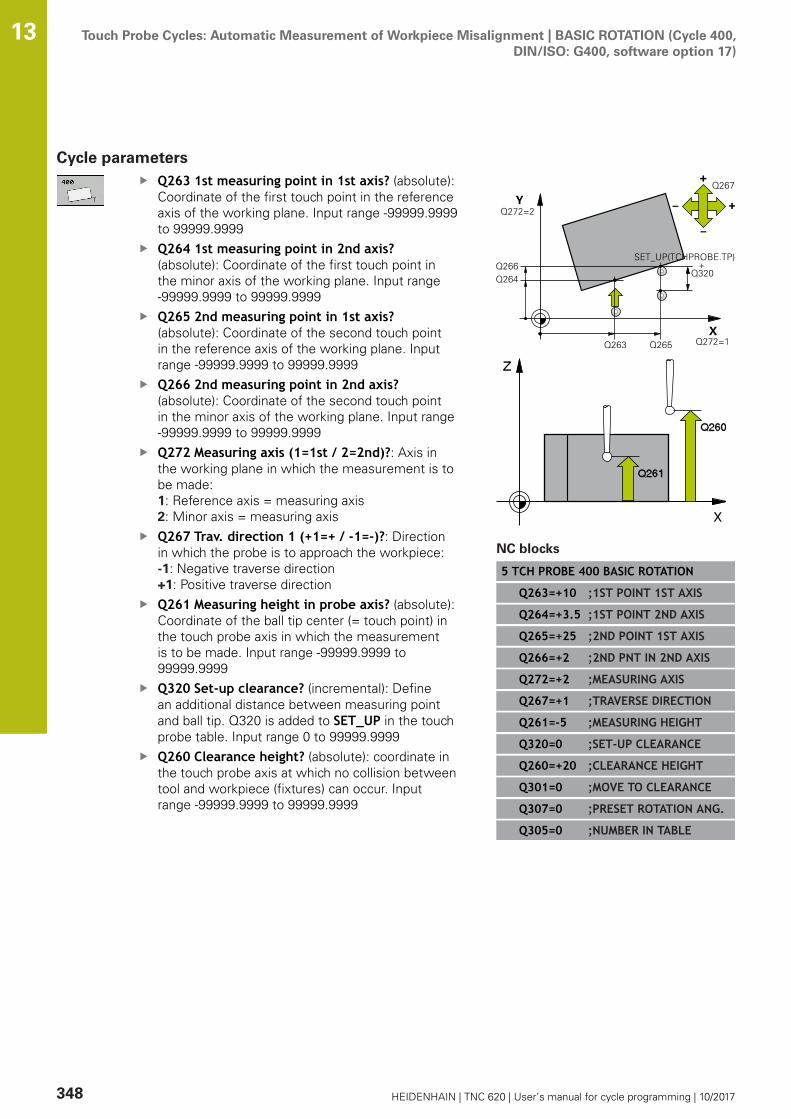
Touch Probe Cycles: Automatic Measurement of Workpiece Misalignment | BASIC ROTATION (Cycle 400,DIN/ISO: G400, software option 17)
13
348 HEIDENHAIN | TNC 620 | User’s manual for cycle programming | 10/2017
Cycle parametersQ263 1st measuring point in 1st axis? (absolute):Coordinate of the first touch point in the referenceaxis of the working plane. Input range -99999.9999to 99999.9999Q264 1st measuring point in 2nd axis?(absolute): Coordinate of the first touch point inthe minor axis of the working plane. Input range-99999.9999 to 99999.9999Q265 2nd measuring point in 1st axis?(absolute): Coordinate of the second touch pointin the reference axis of the working plane. Inputrange -99999.9999 to 99999.9999Q266 2nd measuring point in 2nd axis?(absolute): Coordinate of the second touch pointin the minor axis of the working plane. Input range-99999.9999 to 99999.9999Q272 Measuring axis (1=1st / 2=2nd)?: Axis inthe working plane in which the measurement is tobe made:1: Reference axis = measuring axis2: Minor axis = measuring axisQ267 Trav. direction 1 (+1=+ / -1=-)?: Directionin which the probe is to approach the workpiece:-1: Negative traverse direction+1: Positive traverse directionQ261 Measuring height in probe axis? (absolute):Coordinate of the ball tip center (= touch point) inthe touch probe axis in which the measurementis to be made. Input range -99999.9999 to99999.9999Q320 Set-up clearance? (incremental): Definean additional distance between measuring pointand ball tip. Q320 is added to SET_UP in the touchprobe table. Input range 0 to 99999.9999Q260 Clearance height? (absolute): coordinate inthe touch probe axis at which no collision betweentool and workpiece (fixtures) can occur. Inputrange -99999.9999 to 99999.9999
NC blocks
5 TCH PROBE 400 BASIC ROTATION
Q263=+10 ;1ST POINT 1ST AXIS
Q264=+3.5 ;1ST POINT 2ND AXIS
Q265=+25 ;2ND POINT 1ST AXIS
Q266=+2 ;2ND PNT IN 2ND AXIS
Q272=+2 ;MEASURING AXIS
Q267=+1 ;TRAVERSE DIRECTION
Q261=-5 ;MEASURING HEIGHT
Q320=0 ;SET-UP CLEARANCE
Q260=+20 ;CLEARANCE HEIGHT
Q301=0 ;MOVE TO CLEARANCE
Q307=0 ;PRESET ROTATION ANG.
Q305=0 ;NUMBER IN TABLE
Touch Probe Cycles: Automatic Measurement of Workpiece Misalignment | BASIC ROTATION (Cycle 400,DIN/ISO: G400, software option 17)
13
HEIDENHAIN | TNC 620 | User’s manual for cycle programming | 10/2017 349
Q301 Move to clearance height (0/1)?: Definitionof how the touch probe is to move between themeasuring points:0: Move at measuring height between measuringpoints1: Move at clearance height between measuringpointsQ307 Preset value for rotation angle (absolute):If the misalignment is to be measured against astraight line other than the reference axis, enterthe angle of this reference line. The TNC willthen calculate the difference between the valuemeasured and the angle of the reference linefor the basic rotation. Input range -360.000 to360.000Q305 Preset number in table?: Enter the numberin the preset table in which the TNC is to save themeasured basic rotation. If you enter Q305=0, theTNC automatically places the determined basicrotation in the ROT menu of the Manual Operationmode. Input range 0 to 99999

Touch Probe Cycles: Automatic Measurement of Workpiece Misalignment | BASIC ROTATION over two holes(Cycle 401, DIN/ISO: G401, software option 17)
13
350 HEIDENHAIN | TNC 620 | User’s manual for cycle programming | 10/2017
13.3 BASIC ROTATION over two holes (Cycle401, DIN/ISO: G401, software option 17)
Cycle runTouch Probe Cycle 401 measures the centers of two holes. Thenthe TNC calculates the angle between the reference axis in theworking plane and the line connecting the hole centers. Withthe basic rotation function, the TNC compensates the calculatedvalue. As an alternative, you can also compensate the determinedmisalignment by rotating the rotary table.1 Following the positioning logic, the TNC positions the touch
probe at rapid traverse (value from FMAX column) (see"Executing touch probe cycles", Page 339) to the center of thefirst hole 1.
2 Then the probe moves to the entered measuring height andprobes four points to find the first hole center.
3 The touch probe returns to the clearance height and then to theposition entered as center of the second hole 2.
4 The TNC moves the touch probe to the entered measuringheight and probes four points to find the second hole center.
5 Then the TNC returns the touch probe to the clearance heightand performs the basic rotation.
Touch Probe Cycles: Automatic Measurement of Workpiece Misalignment | BASIC ROTATION over two holes(Cycle 401, DIN/ISO: G401, software option 17)
13
HEIDENHAIN | TNC 620 | User’s manual for cycle programming | 10/2017 351
Please note while programming:
Before a cycle definition you must have programmed atool call to define the touch probe axis.The TNC will reset an active basic rotation at thebeginning of the cycle.If you want to compensate the misalignment by rotatingthe rotary table, the TNC will automatically use thefollowing rotary axes:
C for tool axis ZB for tool axis YA for tool axis X
NOTICEDanger of collision!
Cycles for coordinate transformation must not be active duringexecution of the touch probe cycles.
Do not activate the following cycles before using touch probecycles: Cycle 7 DATUM SHIFT,Cycle 8 MIRROR IMAGE, Cycle10 ROTATION,Cycle 11 SCALING and 26 AXIS-SPECIFICSCALINGReset any coordinate transformations beforehand

Touch Probe Cycles: Automatic Measurement of Workpiece Misalignment | BASIC ROTATION over two holes(Cycle 401, DIN/ISO: G401, software option 17)
13
352 HEIDENHAIN | TNC 620 | User’s manual for cycle programming | 10/2017
Cycle parametersQ268 1st hole: center in 1st axis? (absolute):Center of the first hole in the reference axis ofthe working plane. Input range -99999.9999 to99999.9999Q269 1st hole: center in 2nd axis? (absolute):Center of the first hole in the minor axis ofthe working plane. Input range -99999.9999 to99999.9999Q270 2nd hole: center in 1st axis? (absolute):Center of the second hole in the reference axisof the working plane. Input range -99999.9999 to99999.9999Q271 2nd hole: center in 2nd axis? (absolute):Center of the second hole in the minor axis ofthe working plane. Input range -99999.9999 to99999.9999Q261 Measuring height in probe axis? (absolute):Coordinate of the ball tip center (= touch point) inthe touch probe axis in which the measurementis to be made. Input range -99999.9999 to99999.9999Q260 Clearance height? (absolute): coordinate inthe touch probe axis at which no collision betweentool and workpiece (fixtures) can occur. Inputrange -99999.9999 to 99999.9999Q307 Preset value for rotation angle (absolute):If the misalignment is to be measured against astraight line other than the reference axis, enterthe angle of this reference line. The TNC willthen calculate the difference between the valuemeasured and the angle of the reference linefor the basic rotation. Input range -360.000 to360.000
NC blocks
5 TCH PROBE 401 ROT OF 2 HOLES
Q268=-37 ;1ST CENTER 1ST AXIS
Q269=+12 ;1ST CENTER 2ND AXIS
Q270=+75 ;2ND CENTER 1ST AXIS
Q271=+20 ;2ND CENTER 2ND AXIS
Q261=-5 ;MEASURING HEIGHT
Q260=+20 ;CLEARANCE HEIGHT
Q307=0 ;PRESET ROTATION ANG.
Q305=0 ;NUMBER IN TABLE
Q402=0 ;COMPENSATION
Q337=0 ;SET TO ZERO
Touch Probe Cycles: Automatic Measurement of Workpiece Misalignment | BASIC ROTATION over two holes(Cycle 401, DIN/ISO: G401, software option 17)
13
HEIDENHAIN | TNC 620 | User’s manual for cycle programming | 10/2017 353
Q305 Number in table? Enter the number of arow from the preset table. The TNC enters thespecific entry in this row: Input range: 0 to 99999 Q305 = 0: The rotary axis is set to zero in row 0of the preset table. An entry is therefore made inthe OFFSET column. (Example: An entry is madein C_OFFS with tool axis Z). Additionally, all othervalues (X, Y, Z, etc.) of the currently active presetare saved in row 0 of the preset table. The presetfrom row 0 is also activated. Q305 > 0: The rotary axis is set to zero in the rowof the preset table specified here. An entry istherefore made in the specific OFFSET column ofthe preset table. (Example: An entry is made inC_OFFS with tool axis Z). Q305 depends on the following parameters: Q337 = 0 and simultaneously Q402 = 0: A basicrotation is set in the row specified by Q305.(Example: With tool axis Z, a basic rotation entry ismade in column SPC)Q337 = 0 and simultaneously Q402 = 1:Parameter Q305 is not effectiveQ337 = 1 Parameter Q305 is effective asdescribed aboveQ402 Basic rotation/alignment (0/1): Definewhether the TNC sets the measured misalignmentas basic rotation or aligns it via rotary tablerotation:0: Set basic rotation: Here the TNC saves thebasic rotation (Example: With tool axis Z the TNCuses the column SPC) 1: Perform rotary table rotation: An entry is madeinto the specific Offset column of the presettable (Example: With tool axis Z the TNC uses thecolumn C_Offs), the specific axis also rotatesQ337 Set to zero after alignment?: Definewhether the TNC sets the position display of thespecific rotary axis after alignment to 0: 0: After alignment the position display is not set to0 1: After alignment the position display is set to 0 ifyou previously defined Q402=1
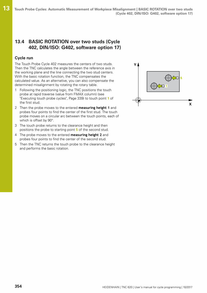
Touch Probe Cycles: Automatic Measurement of Workpiece Misalignment | BASIC ROTATION over two studs(Cycle 402, DIN/ISO: G402, software option 17)
13
354 HEIDENHAIN | TNC 620 | User’s manual for cycle programming | 10/2017
13.4 BASIC ROTATION over two studs (Cycle402, DIN/ISO: G402, software option 17)
Cycle runThe Touch Probe Cycle 402 measures the centers of two studs.Then the TNC calculates the angle between the reference axis inthe working plane and the line connecting the two stud centers.With the basic rotation function, the TNC compensates thecalculated value. As an alternative, you can also compensate thedetermined misalignment by rotating the rotary table.1 Following the positioning logic, the TNC positions the touch
probe at rapid traverse (value from FMAX column) (see"Executing touch probe cycles", Page 339) to touch point 1 ofthe first stud.
2 Then the probe moves to the entered measuring height 1 andprobes four points to find the center of the first stud. The touchprobe moves on a circular arc between the touch points, each ofwhich is offset by 90°.
3 The touch probe returns to the clearance height and thenpositions the probe to starting point 5 of the second stud.
4 The probe moves to the entered measuring height 2 andprobes four points to find the center of the second stud.
5 Then the TNC returns the touch probe to the clearance heightand performs the basic rotation.

Touch Probe Cycles: Automatic Measurement of Workpiece Misalignment | BASIC ROTATION over two studs(Cycle 402, DIN/ISO: G402, software option 17)
13
HEIDENHAIN | TNC 620 | User’s manual for cycle programming | 10/2017 355
Please note while programming:
Before a cycle definition you must have programmed atool call to define the touch probe axis.The TNC will reset an active basic rotation at thebeginning of the cycle.
If you want to compensate the misalignment by rotatingthe rotary table, the TNC will automatically use thefollowing rotary axes:
C for tool axis ZB for tool axis YA for tool axis X
NOTICEDanger of collision!
Cycles for coordinate transformation must not be active duringexecution of the touch probe cycles.
Do not activate the following cycles before using touch probecycles: Cycle 7 DATUM SHIFT,Cycle 8 MIRROR IMAGE, Cycle10 ROTATION,Cycle 11 SCALING and 26 AXIS-SPECIFICSCALINGReset any coordinate transformations beforehand
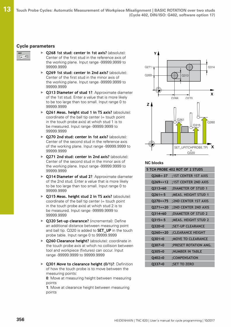
Touch Probe Cycles: Automatic Measurement of Workpiece Misalignment | BASIC ROTATION over two studs(Cycle 402, DIN/ISO: G402, software option 17)
13
356 HEIDENHAIN | TNC 620 | User’s manual for cycle programming | 10/2017
Cycle parametersQ268 1st stud: center in 1st axis? (absolute):Center of the first stud in the reference axis ofthe working plane. Input range -99999.9999 to99999.9999Q269 1st stud: center in 2nd axis? (absolute):Center of the first stud in the minor axis ofthe working plane. Input range -99999.9999 to99999.9999Q313 Diameter of stud 1?: Approximate diameterof the 1st stud. Enter a value that is more likelyto be too large than too small. Input range 0 to99999.9999Q261 Meas. height stud 1 in TS axis? (absolute):coordinate of the ball tip center (= touch pointin the touch probe axis) at which stud 1 is tobe measured. Input range -99999.9999 to99999.9999Q270 2nd stud: center in 1st axis? (absolute):Center of the second stud in the reference axisof the working plane. Input range -99999.9999 to99999.9999Q271 2nd stud: center in 2nd axis? (absolute):Center of the second stud in the minor axis ofthe working plane. Input range -99999.9999 to99999.9999Q314 Diameter of stud 2?: Approximate diameterof the 2nd stud. Enter a value that is more likelyto be too large than too small. Input range 0 to99999.9999Q315 Meas. height stud 2 in TS axis? (absolute):coordinate of the ball tip center (= touch pointin the touch probe axis) at which stud 2 is tobe measured. Input range -99999.9999 to99999.9999Q320 Set-up clearance? (incremental): Definean additional distance between measuring pointand ball tip. Q320 is added to SET_UP in the touchprobe table. Input range 0 to 99999.9999Q260 Clearance height? (absolute): coordinate inthe touch probe axis at which no collision betweentool and workpiece (fixtures) can occur. Inputrange -99999.9999 to 99999.9999
Q301 Move to clearance height (0/1)?: Definitionof how the touch probe is to move between themeasuring points:0: Move at measuring height between measuringpoints1: Move at clearance height between measuringpoints
NC blocks
5 TCH PROBE 402 ROT OF 2 STUDS
Q268=-37 ;1ST CENTER 1ST AXIS
Q269=+12 ;1ST CENTER 2ND AXIS
Q313=60 ;DIAMETER OF STUD 1
Q261=-5 ;MEAS. HEIGHT STUD 1
Q270=+75 ;2ND CENTER 1ST AXIS
Q271=+20 ;2ND CENTER 2ND AXIS
Q314=60 ;DIAMETER OF STUD 2
Q315=-5 ;MEAS. HEIGHT STUD 2
Q320=0 ;SET-UP CLEARANCE
Q260=+20 ;CLEARANCE HEIGHT
Q301=0 ;MOVE TO CLEARANCE
Q307=0 ;PRESET ROTATION ANG.
Q305=0 ;NUMBER IN TABLE
Q402=0 ;COMPENSATION
Q337=0 ;SET TO ZERO
Touch Probe Cycles: Automatic Measurement of Workpiece Misalignment | BASIC ROTATION over two studs(Cycle 402, DIN/ISO: G402, software option 17)
13
HEIDENHAIN | TNC 620 | User’s manual for cycle programming | 10/2017 357
Q307 Preset value for rotation angle (absolute):If the misalignment is to be measured against astraight line other than the reference axis, enterthe angle of this reference line. The TNC willthen calculate the difference between the valuemeasured and the angle of the reference linefor the basic rotation. Input range -360.000 to360.000Q305 Number in table? Enter the number of arow from the preset table. The TNC enters thespecific entry in this row: Input range: 0 to 99999 Q305 = 0: The rotary axis is set to zero in row 0of the preset table. An entry is therefore made inthe OFFSET column. (Example: An entry is madein C_OFFS with tool axis Z). Additionally, all othervalues (X, Y, Z, etc.) of the currently active presetare saved in row 0 of the preset table. The presetfrom row 0 is also activated. Q305 > 0: The rotary axis is set to zero in the rowof the preset table specified here. An entry istherefore made in the specific OFFSET column ofthe preset table. (Example: An entry is made inC_OFFS with tool axis Z). Q305 depends on the following parameters: Q337 = 0 and simultaneously Q402 = 0: A basicrotation is set in the row specified by Q305.(Example: With tool axis Z, a basic rotation entry ismade in column SPC)Q337 = 0 and simultaneously Q402 = 1:Parameter Q305 is not effectiveQ337 = 1 Parameter Q305 is effective asdescribed aboveQ402 Basic rotation/alignment (0/1): Definewhether the TNC sets the measured misalignmentas basic rotation or aligns it via rotary tablerotation:0: Set basic rotation: Here the TNC saves thebasic rotation (Example: With tool axis Z the TNCuses the column SPC) 1: Perform rotary table rotation: An entry is madeinto the specific Offset column of the presettable (Example: With tool axis Z the TNC uses thecolumn C_Offs), the specific axis also rotatesQ337 Set to zero after alignment?: Definewhether the TNC sets the position display of thespecific rotary axis after alignment to 0: 0: After alignment the position display is not set to0 1: After alignment the position display is set to 0 ifyou previously defined Q402=1
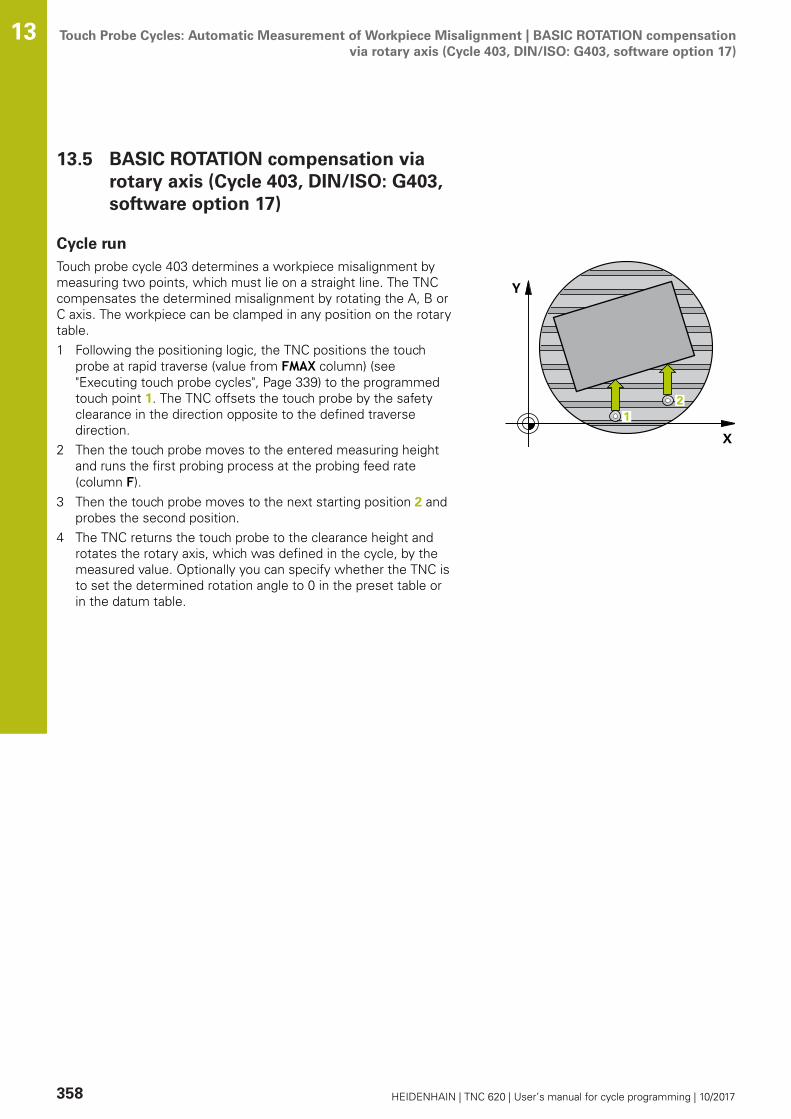
Touch Probe Cycles: Automatic Measurement of Workpiece Misalignment | BASIC ROTATION compensationvia rotary axis (Cycle 403, DIN/ISO: G403, software option 17)
13
358 HEIDENHAIN | TNC 620 | User’s manual for cycle programming | 10/2017
13.5 BASIC ROTATION compensation viarotary axis (Cycle 403, DIN/ISO: G403,software option 17)
Cycle runTouch probe cycle 403 determines a workpiece misalignment bymeasuring two points, which must lie on a straight line. The TNCcompensates the determined misalignment by rotating the A, B orC axis. The workpiece can be clamped in any position on the rotarytable.1 Following the positioning logic, the TNC positions the touch
probe at rapid traverse (value from FMAX column) (see"Executing touch probe cycles", Page 339) to the programmedtouch point 1. The TNC offsets the touch probe by the safetyclearance in the direction opposite to the defined traversedirection.
2 Then the touch probe moves to the entered measuring heightand runs the first probing process at the probing feed rate(column F).
3 Then the touch probe moves to the next starting position 2 andprobes the second position.
4 The TNC returns the touch probe to the clearance height androtates the rotary axis, which was defined in the cycle, by themeasured value. Optionally you can specify whether the TNC isto set the determined rotation angle to 0 in the preset table orin the datum table.
Touch Probe Cycles: Automatic Measurement of Workpiece Misalignment | BASIC ROTATION compensationvia rotary axis (Cycle 403, DIN/ISO: G403, software option 17)
13
HEIDENHAIN | TNC 620 | User’s manual for cycle programming | 10/2017 359
Please note while programming:
NOTICEDanger of collision!
A collision may occur if the TNC automatically positions therotary axis.
Check for possible collisions between the tool and anyelements positioned on the tableSelect the clearance height to prevent collisions
NOTICEDanger of collision!
If you enter the value 0 in parameter Q312 Axis forcompensating movement?, the cycle automatically determinesthe rotary axis to be aligned (recommended setting). Dependingon the sequence of the probing points, an angle is determined.The measured angle goes from the first to the second probingpoint. If you select the A, B or C axis as compensation axis inparameter Q312, the cycle determines the angle, regardless ofthe sequence of the probing points The calculated angle lies inthe range from –90° to +90°.
After alignment, check the position of the rotary axis.
NOTICEDanger of collision!
Cycles for coordinate transformation must not be active duringexecution of the touch probe cycles.
Do not activate the following cycles before using touch probecycles: Cycle 7 DATUM SHIFT,Cycle 8 MIRROR IMAGE, Cycle10 ROTATION,Cycle 11 SCALING and 26 AXIS-SPECIFICSCALINGReset any coordinate transformations beforehand
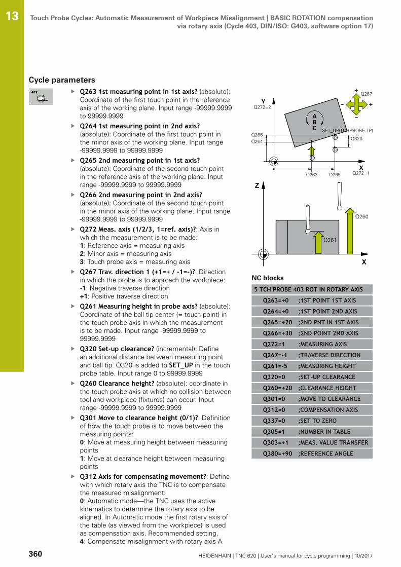
Touch Probe Cycles: Automatic Measurement of Workpiece Misalignment | BASIC ROTATION compensationvia rotary axis (Cycle 403, DIN/ISO: G403, software option 17)
13
360 HEIDENHAIN | TNC 620 | User’s manual for cycle programming | 10/2017
Cycle parametersQ263 1st measuring point in 1st axis? (absolute):Coordinate of the first touch point in the referenceaxis of the working plane. Input range -99999.9999to 99999.9999Q264 1st measuring point in 2nd axis?(absolute): Coordinate of the first touch point inthe minor axis of the working plane. Input range-99999.9999 to 99999.9999Q265 2nd measuring point in 1st axis?(absolute): Coordinate of the second touch pointin the reference axis of the working plane. Inputrange -99999.9999 to 99999.9999Q266 2nd measuring point in 2nd axis?(absolute): Coordinate of the second touch pointin the minor axis of the working plane. Input range-99999.9999 to 99999.9999Q272 Meas. axis (1/2/3, 1=ref. axis)?: Axis inwhich the measurement is to be made:1: Reference axis = measuring axis2: Minor axis = measuring axis3: Touch probe axis = measuring axisQ267 Trav. direction 1 (+1=+ / -1=-)?: Directionin which the probe is to approach the workpiece:-1: Negative traverse direction+1: Positive traverse directionQ261 Measuring height in probe axis? (absolute):Coordinate of the ball tip center (= touch point) inthe touch probe axis in which the measurementis to be made. Input range -99999.9999 to99999.9999Q320 Set-up clearance? (incremental): Definean additional distance between measuring pointand ball tip. Q320 is added to SET_UP in the touchprobe table. Input range 0 to 99999.9999Q260 Clearance height? (absolute): coordinate inthe touch probe axis at which no collision betweentool and workpiece (fixtures) can occur. Inputrange -99999.9999 to 99999.9999Q301 Move to clearance height (0/1)?: Definitionof how the touch probe is to move between themeasuring points:0: Move at measuring height between measuringpoints1: Move at clearance height between measuringpointsQ312 Axis for compensating movement?: Definewith which rotary axis the TNC is to compensatethe measured misalignment:0: Automatic mode—the TNC uses the activekinematics to determine the rotary axis to bealigned. In Automatic mode the first rotary axis ofthe table (as viewed from the workpiece) is usedas compensation axis. Recommended setting.4: Compensate misalignment with rotary axis A
NC blocks
5 TCH PROBE 403 ROT IN ROTARY AXIS
Q263=+0 ;1ST POINT 1ST AXIS
Q264=+0 ;1ST POINT 2ND AXIS
Q265=+20 ;2ND PNT IN 1ST AXIS
Q266=+30 ;2ND POINT 2ND AXIS
Q272=1 ;MEASURING AXIS
Q267=-1 ;TRAVERSE DIRECTION
Q261=-5 ;MEASURING HEIGHT
Q320=0 ;SET-UP CLEARANCE
Q260=+20 ;CLEARANCE HEIGHT
Q301=0 ;MOVE TO CLEARANCE
Q312=0 ;COMPENSATION AXIS
Q337=0 ;SET TO ZERO
Q305=1 ;NUMBER IN TABLE
Q303=+1 ;MEAS. VALUE TRANSFER
Q380=+90 ;REFERENCE ANGLE

Touch Probe Cycles: Automatic Measurement of Workpiece Misalignment | BASIC ROTATION compensationvia rotary axis (Cycle 403, DIN/ISO: G403, software option 17)
13
HEIDENHAIN | TNC 620 | User’s manual for cycle programming | 10/2017 361
5: Compensate misalignment with rotary axis B6: Compensate misalignment with rotary axis CQ337 Set to zero after alignment?: Definewhether the TNC should set the angle of thealigned rotary axis to 0 in the preset table or in thedatum table after the alignment.0: Do not set the angle of the rotary axis to 0 inthe table after alignment1: Set the angle of the rotary axis to 0 in the tableafter alignmentQ305 Number in table? Enter the number in thepreset table in which the TNC is to enter the basicrotation. Input range 0 to 99999 Q305 = 0: The rotary axis is set to zero in number0 of the preset table. An entry is made in theOFFSET column. Additionally, all other values (X, Y,Z, etc.) of the currently active preset are saved inrow 0 of the preset table. The preset from row 0 isalso activated. Q305 > 0: Specify the row of the preset table inwhich the TNC should set the rotary axis to zero.An entry is made in the OFFSET column of thepreset table. Q305 depends on the following parameters: Q337 = 0 Parameter Q305 is not effectiveQ337 = 1 Parameter Q305 is effective asdescribed aboveQ312 = 0: Parameter Q305 is effective asdescribed aboveQ312 > 0: The entry in Q305 is ignored. An entryis made in the OFFSET column in the row of thepreset table active when the cycle is calledQ303 Meas. value transfer (0,1)?: Specify if thedetermined basic rotation is to be saved in thedatum table or in the preset table:0: Write the measured basic rotation as datumshift in the active datum table. The referencesystem is the active workpiece coordinate system1: Write the measured basic rotation into thepreset table. The reference system is the machinecoordinate system (REF system).Q380 Ref. angle in ref. axis?: Angle with whichthe TNC is to align the probed straight line. Onlyeffective if the rotary axis = Automatic mode or Cis selected (Q312 = 0 or 6). Input range -360.000to 360.000

Touch Probe Cycles: Automatic Measurement of Workpiece Misalignment | SET BASIC ROTATION (Cycle 404,DIN/ISO: G404, software option 17)
13
362 HEIDENHAIN | TNC 620 | User’s manual for cycle programming | 10/2017
13.6 SET BASIC ROTATION (Cycle 404, DIN/ISO: G404, software option 17)
Cycle runWith Touch Probe Cycle 404, during program run you canautomatically set any basic rotation or save it to the preset table. Youcan also use Cycle 404 if you want to reset an active basic rotation.
NOTICEDanger of collision!
Cycles for coordinate transformation must not be active duringexecution of the touch probe cycles.
Do not activate the following cycles before using touch probecycles: Cycle 7 DATUM SHIFT,Cycle 8 MIRROR IMAGE, Cycle 10ROTATION,Cycle 11 SCALING and 26 AXIS-SPECIFIC SCALINGReset any coordinate transformations beforehand
NC blocks
5 TCH PROBE 404 SET BASIC ROTATION
Q307=+0 ;PRESET ROTATION ANG.
Q305=-1 ;NUMBER IN TABLE
Cycle parametersQ307 Preset value for rotation angle: Angularvalue at which the basic rotation is to be set.Input range -360.000 to 360.000Q305 Preset number in table?: Enter thenumber in the preset table in which the TNC isto save the measured basic rotation. Input range-1 to 99999 If you enter Q305=0 or Q305=-1,the TNC additionally places the determined basicrotation in the basic rotation menu (Probing Rot)of the Manual Operation mode. -1 = Overwrite and activate the active preset0 = Copy the active preset to preset row 0, writethe basic rotation to preset row 0 and activatepreset 0>1 = Save the basic rotation to the specifiedpreset. The preset is not activated
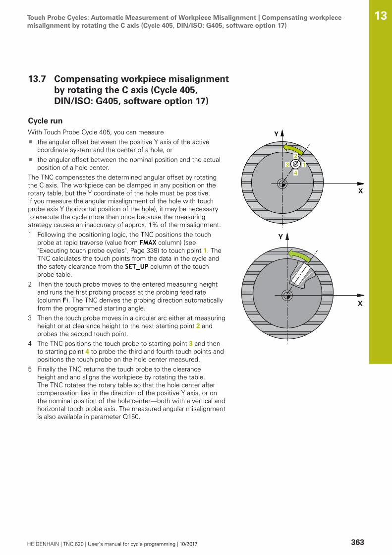
Touch Probe Cycles: Automatic Measurement of Workpiece Misalignment | Compensating workpiecemisalignment by rotating the C axis (Cycle 405, DIN/ISO: G405, software option 17)
13
HEIDENHAIN | TNC 620 | User’s manual for cycle programming | 10/2017 363
13.7 Compensating workpiece misalignmentby rotating the C axis (Cycle 405,DIN/ISO: G405, software option 17)
Cycle runWith Touch Probe Cycle 405, you can measure
the angular offset between the positive Y axis of the activecoordinate system and the center of a hole, orthe angular offset between the nominal position and the actualposition of a hole center.
The TNC compensates the determined angular offset by rotatingthe C axis. The workpiece can be clamped in any position on therotary table, but the Y coordinate of the hole must be positive.If you measure the angular misalignment of the hole with touchprobe axis Y (horizontal position of the hole), it may be necessaryto execute the cycle more than once because the measuringstrategy causes an inaccuracy of approx. 1% of the misalignment.1 Following the positioning logic, the TNC positions the touch
probe at rapid traverse (value from FMAX column) (see"Executing touch probe cycles", Page 339) to touch point 1. TheTNC calculates the touch points from the data in the cycle andthe safety clearance from the SET_UP column of the touchprobe table.
2 Then the touch probe moves to the entered measuring heightand runs the first probing process at the probing feed rate(column F). The TNC derives the probing direction automaticallyfrom the programmed starting angle.
3 Then the touch probe moves in a circular arc either at measuringheight or at clearance height to the next starting point 2 andprobes the second touch point.
4 The TNC positions the touch probe to starting point 3 and thento starting point 4 to probe the third and fourth touch points andpositions the touch probe on the hole center measured.
5 Finally the TNC returns the touch probe to the clearanceheight and and aligns the workpiece by rotating the table.The TNC rotates the rotary table so that the hole center aftercompensation lies in the direction of the positive Y axis, or onthe nominal position of the hole center—both with a vertical andhorizontal touch probe axis. The measured angular misalignmentis also available in parameter Q150.
Touch Probe Cycles: Automatic Measurement of Workpiece Misalignment | Compensating workpiecemisalignment by rotating the C axis (Cycle 405, DIN/ISO: G405, software option 17)
13
364 HEIDENHAIN | TNC 620 | User’s manual for cycle programming | 10/2017
Please note while programming:
Before a cycle definition you must have programmeda tool call to define the touch probe axis.The smaller the angle, the less accurately the TNCcan calculate the circle center. Minimum input value:5°
NOTICEDanger of collision!
If the dimensions of the pocket and the safety clearance do notpermit pre-positioning in the proximity of the touch points, theTNC always starts probing from the center of the pocket. In thiscase the touch probe does not return to the clearance heightbetween the four measuring points.
Make sure that there is no material in the pocket/holeTo prevent a collision between the touch probe and theworkpiece, enter a low estimate for the nominal diameter ofthe pocket (or hole).
NOTICEDanger of collision!
Cycles for coordinate transformation must not be active duringexecution of the touch probe cycles.
Do not activate the following cycles before using touch probecycles: Cycle 7 DATUM SHIFT,Cycle 8 MIRROR IMAGE, Cycle10 ROTATION,Cycle 11 SCALING and 26 AXIS-SPECIFICSCALINGReset any coordinate transformations beforehand

Touch Probe Cycles: Automatic Measurement of Workpiece Misalignment | Compensating workpiecemisalignment by rotating the C axis (Cycle 405, DIN/ISO: G405, software option 17)
13
HEIDENHAIN | TNC 620 | User’s manual for cycle programming | 10/2017 365
Cycle parametersQ321 Center in 1st axis? (absolute): Center of thehole in the reference axis of the working plane.Input range -99999.9999 to 99999.9999Q322 Center in 2nd axis? (absolute): Center ofthe hole in the minor axis of the working plane. Ifyou program Q322 = 0, the TNC aligns the holecenter to the positive Y axis. If you program Q322not equal to 0, then the TNC aligns the hole centerto the nominal position (angle of the hole center).Input range -99999.9999 to 99999.9999Q262 Nominal diameter?: Approximate diameterof the circular pocket (or hole). Enter a value thatis more likely to be too small than too large. Inputrange 0 to 99999.9999Q325 Starting angle? (absolute): Angle betweenthe reference axis of the working plane and thefirst touch point. Input range -360.000 to 360.000Q247 Intermediate stepping angle?(incremental): Angle between two measuringpoints. The algebraic sign of the steppingangle determines the direction of rotation(negative = clockwise) in which the touch probemoves to the next measuring point. If you wish toprobe a circular arc instead of a complete circle,then program the stepping angle to be less than90°. Input range -120.000 to 120.000Q261 Measuring height in probe axis? (absolute):Coordinate of the ball tip center (= touch point) inthe touch probe axis in which the measurementis to be made. Input range -99999.9999 to99999.9999Q320 Set-up clearance? (incremental): Definean additional distance between measuring pointand ball tip. Q320 is added to SET_UP in the touchprobe table. Input range 0 to 99999.9999Q260 Clearance height? (absolute): coordinate inthe touch probe axis at which no collision betweentool and workpiece (fixtures) can occur. Inputrange -99999.9999 to 99999.9999Q301 Move to clearance height (0/1)?: Definitionof how the touch probe is to move between themeasuring points:0: Move at measuring height between measuringpoints1: Move at clearance height between measuringpointsQ337 Set to zero after alignment?: 0: Set display of the C axis to 0 and write theC_Offset of the active row in the datum table>0: Write the measured angular offset in thedatum table. Row number = value of Q337. If a C-axis shift is registered in the datum table, the TNCadds the measured angular misalignment.
NC blocks
5 TCH PROBE 405 ROT IN C AXIS
Q321=+50 ;CENTER IN 1ST AXIS
Q322=+50 ;CENTER IN 2ND AXIS
Q262=10 ;NOMINAL DIAMETER
Q325=+0 ;STARTING ANGLE
Q247=90 ;STEPPING ANGLE
Q261=-5 ;MEASURING HEIGHT
Q320=0 ;SET-UP CLEARANCE
Q260=+20 ;CLEARANCE HEIGHT
Q301=0 ;MOVE TO CLEARANCE
Q337=0 ;SET TO ZERO

Touch Probe Cycles: Automatic Measurement of Workpiece Misalignment | Example: Determining a basicrotation from two holes
13
366 HEIDENHAIN | TNC 620 | User’s manual for cycle programming | 10/2017
13.8 Example: Determining a basic rotationfrom two holes
0 BEGIN P GM CYC401 MM
1 TOOL CALL 69 Z
2 TCH PROBE 401 ROT OF 2 HOLES
Q268=+25 ;1ST CENTER 1ST AXIS Center of the 1st hole: X coordinate
Q269=+15 ;1ST CENTER 2ND AXIS Center of the 1st hole: Y coordinate
Q270=+80 ;2ND CENTER 1ST AXIS Center of the 2nd hole: X coordinate
Q271=+35 ;2ND CENTER 2ND AXIS Center of the 2nd hole: Y coordinate
Q261=-5 ;MEASURING HEIGHT Coordinate in the touch probe axis in which themeasurement is made
Q260=+20 ;CLEARANCE HEIGHT Height in the touch probe axis at which the probe cantraverse without collision
Q307=+0 ;PRESET ROTATION ANG. Angle of the reference line
Q305=0 ;NUMBER IN TABLE
Q402=1 ;COMPENSATION Compensate misalignment by rotating the rotary table
Q337=1 ;SET TO ZERO Set the display to zero after the alignment
3 CALL PGM 35K47 Call part program
4 END PGM CYC401 MM

14Touch Probe
Cycles: AutomaticPresetting
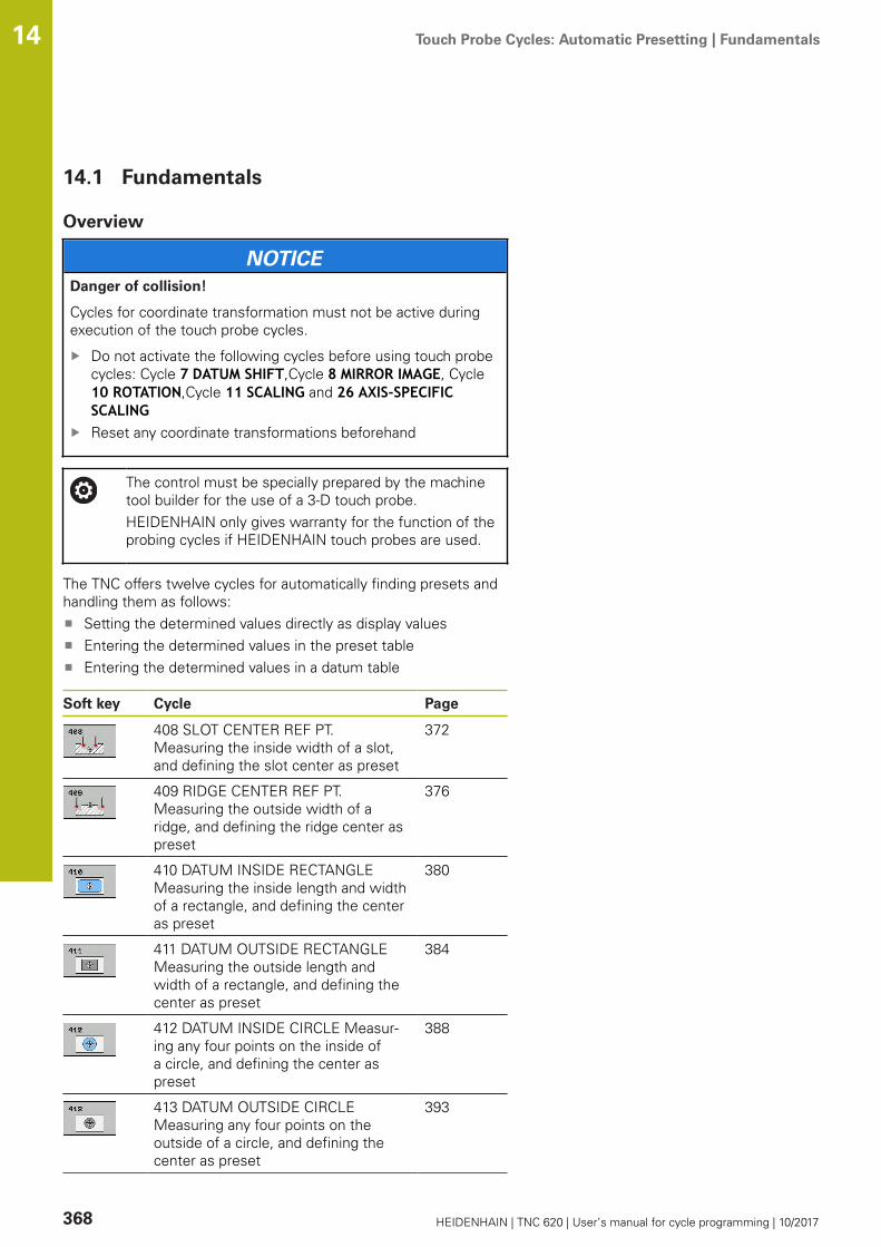
Touch Probe Cycles: Automatic Presetting | Fundamentals 14
368 HEIDENHAIN | TNC 620 | User’s manual for cycle programming | 10/2017
14.1 Fundamentals
Overview
NOTICEDanger of collision!
Cycles for coordinate transformation must not be active duringexecution of the touch probe cycles.
Do not activate the following cycles before using touch probecycles: Cycle 7 DATUM SHIFT,Cycle 8 MIRROR IMAGE, Cycle10 ROTATION,Cycle 11 SCALING and 26 AXIS-SPECIFICSCALINGReset any coordinate transformations beforehand
The control must be specially prepared by the machinetool builder for the use of a 3-D touch probe.HEIDENHAIN only gives warranty for the function of theprobing cycles if HEIDENHAIN touch probes are used.
The TNC offers twelve cycles for automatically finding presets andhandling them as follows:
Setting the determined values directly as display valuesEntering the determined values in the preset tableEntering the determined values in a datum table
Soft key Cycle Page
408 SLOT CENTER REF PT. Measuring the inside width of a slot,and defining the slot center as preset
372
409 RIDGE CENTER REF PT. Measuring the outside width of aridge, and defining the ridge center aspreset
376
410 DATUM INSIDE RECTANGLE Measuring the inside length and widthof a rectangle, and defining the centeras preset
380
411 DATUM OUTSIDE RECTANGLE Measuring the outside length andwidth of a rectangle, and defining thecenter as preset
384
412 DATUM INSIDE CIRCLE Measur-ing any four points on the inside ofa circle, and defining the center aspreset
388
413 DATUM OUTSIDE CIRCLE Measuring any four points on theoutside of a circle, and defining thecenter as preset
393

Touch Probe Cycles: Automatic Presetting | Fundamentals 14
HEIDENHAIN | TNC 620 | User’s manual for cycle programming | 10/2017 369
Soft key Cycle Page
414 DATUM OUTSIDE CORNER Measuring two lines from the outsideof the angle, and defining the intersec-tion as preset
398
415 DATUM INSIDE CORNER Measuring two lines from within theangle, and defining the intersection aspreset
403
416 DATUM CIRCLE CENTER (2nd soft-key level) Measuring anythree holes on a bolt hole circle, anddefining the bolt-hole center as preset
408
417 DATUM IN TS AXIS (2nd soft-key level) Measuring anyposition in the touch probe axis anddefining it as preset
412
418 DATUM FROM 4 HOLES (2nd soft-key level) Measuring 4 holescrosswise and defining the intersec-tion of the lines between them aspreset
414
419 DATUM IN ONE AXIS (2nd soft-key row) Measuring anyposition in any axis and defining it aspreset
418

Touch Probe Cycles: Automatic Presetting | Fundamentals 14
370 HEIDENHAIN | TNC 620 | User’s manual for cycle programming | 10/2017
Characteristics common to all touch probe cycles forpresetting
You can also run the Touch Probe Cycles 408 to 419during an active rotation (basic rotation or Cycle 10).
Touch-probe axis and presets
From the touch probe axis that you have defined in the measuringprogram the TNC determines the working plane for the preset.
Active touch probe axis Set preset in
Z X and Y
Y Z and X
X Y and Z
Saving the calculated preset
In all cycles for presetting you can use the input parameters Q303and Q305 to define how the TNC is to save the calculated preset:
Q305 = 0, Q303 = any value: The TNC sets the calculatedpreset in the display. The new preset is active immediately. Atthe same time, the TNC saves the preset set in the display bythe cycle in line 0 of the preset table.Q305 not equal to 0, Q303 = –1

Touch Probe Cycles: Automatic Presetting | Fundamentals 14
HEIDENHAIN | TNC 620 | User’s manual for cycle programming | 10/2017 371
This combination can only occur if youread in programs containing Cycles 410 to 418created on a TNC 4xxread in programs containing Cycles 410 to 418created with an older software version on an iTNC530did not specifically define the measured-valuetransfer with parameter Q303 when defining thecycle.
In these cases the TNC outputs an error message, sincethe complete handling of REF-referenced datum tableshas changed. You must define a measured-value transferyourself with parameter Q303.
Q305 not equal to 0, Q303 = 0 The TNC writes the calculatedpreset in the active datum table. The reference system is theactive workpiece coordinate system. The value of parameterQ305 determines the datum number. Activate the datum withCycle 7 in the part program.
Q305 not equal to 0, Q303 = 1 The TNC writes the calculatedpreset in the preset table. The reference system is the machinecoordinate system (REF coordinates). The value of parameterQ305 determines the preset number. Activate the preset withCycle 247 in the part program.
Measurement results in Q parameters
The TNC saves the measurement results of the respective touchprobe cycle in the globally effective Q parameters Q150 to Q160.You can use these parameters in your program. Note the table ofresult parameters listed with every cycle description.

Touch Probe Cycles: Automatic Presetting | SLOT CENTER PRESET (Cycle 408,DIN/ISO: G408, software option 17)
14
372 HEIDENHAIN | TNC 620 | User’s manual for cycle programming | 10/2017
14.2 SLOT CENTER PRESET (Cycle 408,DIN/ISO: G408, software option 17)
Cycle runTouch Probe Cycle 408 finds the center of a slot and definesits center as a preset. If desired, the TNC can also enter thecoordinates into a datum table or the preset table.1 Following the positioning logic, the TNC positions the touch
probe at rapid traverse (value from FMAX column) (see"Executing touch probe cycles", Page 339) to touch point 1. TheTNC calculates the touch points from the data in the cycle andthe safety clearance from the SET_UP column of the touchprobe table.
2 Then the touch probe moves to the entered measuring heightand runs the first probing process at the probing feed rate(column F).
3 Then the touch probe moves either paraxially at measuringheight or at clearance height to the next starting point 2 andprobes the second touch point.
4 Finally the TNC returns the touch probe to the clearance heightand processes the determined preset depending on the cycleparameters Q303 and Q305 (see "Characteristics common toall touch probe cycles for presetting", Page 370) and saves theactual values in the Q parameters listed below.
5 If desired, the TNC subsequently measures the preset in thetouch probe axis in a separate probing.
Parameter number Meaning
Q166 Actual value of measured slot width
Q157 Actual value of the centerline

Touch Probe Cycles: Automatic Presetting | SLOT CENTER PRESET (Cycle 408,DIN/ISO: G408, software option 17)
14
HEIDENHAIN | TNC 620 | User’s manual for cycle programming | 10/2017 373
Please note while programming:
NOTICEDanger of collision!
Cycles for coordinate transformation must not be active duringexecution of the touch probe cycles.
Do not activate the following cycles before using touch probecycles: Cycle 7 DATUM SHIFT,Cycle 8 MIRROR IMAGE, Cycle10 ROTATION,Cycle 11 SCALING and 26 AXIS-SPECIFICSCALINGReset any coordinate transformations beforehand
NOTICEDanger of collision!
To prevent a collision between touch probe and workpiece, entera low estimate for the slot width. If the slot width and the safetyclearance do not permit pre-positioning in the proximity of thetouch points, the TNC always starts probing from the centerof the slot. In this case the touch probe does not return to theclearance height between the two measuring points.
Before a cycle definition you must have programmed a toolcall to define the touch probe axis.

Touch Probe Cycles: Automatic Presetting | SLOT CENTER PRESET (Cycle 408,DIN/ISO: G408, software option 17)
14
374 HEIDENHAIN | TNC 620 | User’s manual for cycle programming | 10/2017
Cycle parametersQ321 Center in 1st axis? (absolute): Center ofthe slot in the reference axis of the working plane.Input range -99999.9999 to 99999.9999Q322 Center in 2nd axis? (absolute): Center ofthe slot in the minor axis of the working plane.Input range -99999.9999 to 99999.9999Q311 Width of slot? (incremental): Width of theslot, regardless of its position in the working plane.Input range 0 to 99999.9999Q272 Measuring axis (1=1st / 2=2nd)?: Axis inthe working plane in which the measurement is tobe made:1: Reference axis = measuring axis2: Minor axis = measuring axisQ261 Measuring height in probe axis? (absolute):Coordinate of the ball tip center (= touch point) inthe touch probe axis in which the measurementis to be made. Input range -99999.9999 to99999.9999Q320 Set-up clearance? (incremental): Definean additional distance between measuring pointand ball tip. Q320 is added to SET_UP in the touchprobe table. Input range 0 to 99999.9999Q260 Clearance height? (absolute): coordinate inthe touch probe axis at which no collision betweentool and workpiece (fixtures) can occur. Inputrange -99999.9999 to 99999.9999Q301 Move to clearance height (0/1)?: Definitionof how the touch probe is to move between themeasuring points:0: Move at measuring height between measuringpoints1: Move at clearance height between measuringpointsQ305 Number in table?: Specify the row numberof the preset table/datum table to which the TNCsaves the coordinates of the center point; inputrange 0 to 9999. The TNC writes the entry to thepreset table or datum table depending on Q303: Q303 = 1: The TNC writes to the preset table.If the active preset is modified this changeimmediately becomes effective. Otherwise anentry is made in the specific row of the presettable without automatic activationQ303 = 0: The TNC writes to the datum table. Thedatum is not automatically activatedQ405 New preset? (absolute): Coordinate in themeasuring axis at which the TNC should set thecalculated slot center. Default setting = 0. Inputrange -99999.9999 to 99999.9999Q303 Meas. value transfer (0,1)?: Specify if thedetermined basic rotation is to be saved in thedatum table or in the preset table:0: Write the measured basic rotation as datum
NC blocks
5 TCH PROBE 408 SLOT CENTER PRESET
Q321=+50 ;CENTER IN 1ST AXIS
Q322=+50 ;CENTER IN 2ND AXIS
Q311=25 ;SLOT WIDTH
Q272=1 ;MEASURING AXIS
Q261=-5 ;MEASURING HEIGHT
Q320=0 ;SET-UP CLEARANCE
Q260=+20 ;CLEARANCE HEIGHT
Q301=0 ;MOVE TO CLEARANCE
Q305=10 ;NUMBER IN TABLE
Q405=+0 ;PRESET
Q303=+1 ;MEAS. VALUE TRANSFER
Q381=1 ;PROBE IN TS AXIS
Q382=+85 ;1ST CO. FOR TS AXIS
Q383=+50 ;2ND CO. FOR TS AXIS
Q384=+0 ;3RD CO. FOR TS AXIS
Q333=+1 ;PRESET

Touch Probe Cycles: Automatic Presetting | SLOT CENTER PRESET (Cycle 408,DIN/ISO: G408, software option 17)
14
HEIDENHAIN | TNC 620 | User’s manual for cycle programming | 10/2017 375
shift in the active datum table. The referencesystem is the active workpiece coordinate system1: Write the measured basic rotation into thepreset table. The reference system is the machinecoordinate system (REF system).Q381 Probe in TS axis? (0/1): Specify whetherthe TNC should also set the preset in the touchprobe axis:0: Do not set the preset in the touch probe axis1: Set the preset in the touch probe axisQ382 Probe TS axis: Coord. 1st axis? (absolute):Coordinate of the probe point in the reference axisof the working plane at which point the preset isto be set in the touch probe axis. Only effective ifQ381 = 1. Input range -99999.9999 to 99999.9999Q383 Probe TS axis: Coord. 2nd axis? (absolute):Coordinate of the probe point in the minor axisof the working plane at which point the preset isto be set in the touch probe axis. Only effective ifQ381 = 1. Input range -99999.9999 to 99999.9999Q384 Probe TS axis: Coord. 3rd axis? (absolute):Coordinate of the probe point in the touch probeaxis, at which point the preset is to be set in thetouch probe axis. Only effective if Q381 = 1. Inputrange -99999.9999 to 99999.9999Q333 New preset in TS axis? (absolute):Coordinate in the touch probe axis at which theTNC should set the preset. Default setting = 0.Input range -99999.9999 to 99999.9999

Touch Probe Cycles: Automatic Presetting | RIDGE CENTER PRESET (Cycle 409, DIN/ISO: G409, softwareoption 17)
14
376 HEIDENHAIN | TNC 620 | User’s manual for cycle programming | 10/2017
14.3 RIDGE CENTER PRESET (Cycle 409, DIN/ISO: G409, software option 17)
Cycle runTouch Probe Cycle 409 finds the center of a ridge and defines itscenter as preset. If desired, the TNC can also enter the coordinatesinto a datum table or the preset table.1 Following the positioning logic, the TNC positions the touch
probe at rapid traverse (value from FMAX column) (see"Executing touch probe cycles", Page 339) to touch point 1. TheTNC calculates the touch points from the data in the cycle andthe safety clearance from the SET_UP column of the touchprobe table.
2 Then the touch probe moves to the entered measuring heightand runs the first probing process at the probing feed rate(column F).
3 Then the touch probe moves at clearance height to the nexttouch point 2 and probes the second touch point.
4 Finally the TNC returns the touch probe to the clearance heightand processes the determined preset depending on the cycleparameters Q303 and Q305 (see "Characteristics common toall touch probe cycles for presetting", Page 370) and saves theactual values in the Q parameters listed below.
5 If desired, the TNC subsequently measures the preset in thetouch probe axis in a separate probing.
Parameter number Meaning
Q166 Actual value of measured ridge width
Q157 Actual value of the centerline
Touch Probe Cycles: Automatic Presetting | RIDGE CENTER PRESET (Cycle 409, DIN/ISO: G409, softwareoption 17)
14
HEIDENHAIN | TNC 620 | User’s manual for cycle programming | 10/2017 377
Please note while programming:
NOTICEDanger of collision!
Cycles for coordinate transformation must not be active duringexecution of the touch probe cycles.
Do not activate the following cycles before using touch probecycles: Cycle 7 DATUM SHIFT,Cycle 8 MIRROR IMAGE, Cycle10 ROTATION,Cycle 11 SCALING and 26 AXIS-SPECIFICSCALINGReset any coordinate transformations beforehand
NOTICEDanger of collision!
To prevent a collision between touch probe and workpiece, entera high estimate for the ridge width.
Before a cycle definition you must have programmed a toolcall to define the touch probe axis.

Touch Probe Cycles: Automatic Presetting | RIDGE CENTER PRESET (Cycle 409, DIN/ISO: G409, softwareoption 17)
14
378 HEIDENHAIN | TNC 620 | User’s manual for cycle programming | 10/2017
Cycle parametersQ321 Center in 1st axis? (absolute): Center of theridge in the reference axis of the working plane.Input range -99999.9999 to 99999.9999Q322 Center in 2nd axis? (absolute): Center ofthe ridge in the minor axis of the working plane.Input range -99999.9999 to 99999.9999Q311 Ridge width? (incremental): Width of theridge, regardless of its position in the workingplane. Input range 0 to 99999.9999Q272 Measuring axis (1=1st / 2=2nd)?: Axis inthe working plane in which the measurement is tobe made:1: Reference axis = measuring axis2: Minor axis = measuring axisQ261 Measuring height in probe axis? (absolute):Coordinate of the ball tip center (= touch point) inthe touch probe axis in which the measurementis to be made. Input range -99999.9999 to99999.9999Q320 Set-up clearance? (incremental): Definean additional distance between measuring pointand ball tip. Q320 is added to SET_UP in the touchprobe table. Input range 0 to 99999.9999Q260 Clearance height? (absolute): coordinate inthe touch probe axis at which no collision betweentool and workpiece (fixtures) can occur. Inputrange -99999.9999 to 99999.9999Q305 Number in table?: Specify the row numberof the preset table/datum table to which the TNCsaves the coordinates of the center point; inputrange 0 to 9999. The TNC writes the entry to thepreset table or datum table depending on Q303: Q303 = 1: The TNC writes to the preset table.If the active preset is modified this changeimmediately becomes effective. Otherwise anentry is made in the specific row of the presettable without automatic activationQ303 = 0: The TNC writes to the datum table. Thedatum is not automatically activated
NC blocks
5 TCH PROBE 409 RIDGE CENTERPRESET
Q321=+50 ;CENTER IN 1ST AXIS
Q322=+50 ;CENTER IN 2ND AXIS
Q311=25 ;RIDGE WIDTH
Q272=1 ;MEASURING AXIS
Q261=-5 ;MEASURING HEIGHT
Q320=0 ;SET-UP CLEARANCE
Q260=+20 ;CLEARANCE HEIGHT
Q305=10 ;NUMBER IN TABLE
Q405=+0 ;PRESET
Q303=+1 ;MEAS. VALUE TRANSFER

Touch Probe Cycles: Automatic Presetting | RIDGE CENTER PRESET (Cycle 409, DIN/ISO: G409, softwareoption 17)
14
HEIDENHAIN | TNC 620 | User’s manual for cycle programming | 10/2017 379
Q405 New preset? (absolute): Coordinate in themeasuring axis at which the TNC should set thecalculated ridge center. Default setting = 0. Inputrange -99999.9999 to 99999.9999Q303 Meas. value transfer (0,1)?: Specify if thedetermined basic rotation is to be saved in thedatum table or in the preset table:0: Write the measured basic rotation as datumshift in the active datum table. The referencesystem is the active workpiece coordinate system1: Write the measured basic rotation into thepreset table. The reference system is the machinecoordinate system (REF system).Q381 Probe in TS axis? (0/1): Specify whetherthe TNC should also set the preset in the touchprobe axis:0: Do not set the preset in the touch probe axis1: Set the preset in the touch probe axisQ382 Probe TS axis: Coord. 1st axis? (absolute):Coordinate of the probe point in the reference axisof the working plane at which point the preset isto be set in the touch probe axis. Only effective ifQ381 = 1. Input range -99999.9999 to 99999.9999Q383 Probe TS axis: Coord. 2nd axis? (absolute):Coordinate of the probe point in the minor axisof the working plane at which point the preset isto be set in the touch probe axis. Only effective ifQ381 = 1. Input range -99999.9999 to 99999.9999Q384 Probe TS axis: Coord. 3rd axis? (absolute):Coordinate of the probe point in the touch probeaxis, at which point the preset is to be set in thetouch probe axis. Only effective if Q381 = 1. Inputrange -99999.9999 to 99999.9999Q333 New preset in TS axis? (absolute):Coordinate in the touch probe axis at which theTNC should set the preset. Default setting = 0.Input range -99999.9999 to 99999.9999
Q381=1 ;PROBE IN TS AXIS
Q382=+85 ;1ST CO. FOR TS AXIS
Q383=+50 ;2ND CO. FOR TS AXIS
Q384=+0 ;3RD CO. FOR TS AXIS
Q333=+1 ;PRESET

Touch Probe Cycles: Automatic Presetting | PRESET FROM INSIDE OF RECTANGLE (Cycle 410,DIN/ISO: G410, software option 17)
14
380 HEIDENHAIN | TNC 620 | User’s manual for cycle programming | 10/2017
14.4 PRESET FROM INSIDE OF RECTANGLE(Cycle 410, DIN/ISO: G410, softwareoption 17)
Cycle runTouch Probe Cycle 410 finds the center of a rectangular pocket anddefines its center as preset. If desired, the TNC can also enter thecoordinates into a datum table or the preset table.1 Following the positioning logic, the TNC positions the touch
probe at rapid traverse (value from FMAX column) (see"Executing touch probe cycles", Page 339) to touch point 1. TheTNC calculates the touch points from the data in the cycle andthe safety clearance from the SET_UP column of the touchprobe table.
2 Then the touch probe moves to the entered measuring heightand runs the first probing process at the probing feed rate(column F).
3 Then the touch probe moves either paraxially at measuringheight or at clearance height to the next starting point 2 andprobes the second touch point.
4 The TNC positions the probe to starting point 3 and then tostarting point 4 to probe the third and fourth touch points.
5 Finally the TNC returns the touch probe to the clearance heightand processes the determined preset depending on the cycleparameters Q303 and Q305 (see "Characteristics common to alltouch probe cycles for presetting", Page 370).
6 If desired, the TNC subsequently measures the preset in thetouch probe axis in a separate probing and saves the actualvalues in the following Q parameters.
Parameter number Meaning
Q151 Actual value of center in reference axis
Q152 Actual value of center in minor axis
Q154 Actual value of length in the referenceaxis
Q155 Actual value of length in the minor axis
Touch Probe Cycles: Automatic Presetting | PRESET FROM INSIDE OF RECTANGLE (Cycle 410,DIN/ISO: G410, software option 17)
14
HEIDENHAIN | TNC 620 | User’s manual for cycle programming | 10/2017 381
Please note while programming:
NOTICEDanger of collision!
Cycles for coordinate transformation must not be active duringexecution of the touch probe cycles.
Do not activate the following cycles before using touch probecycles: Cycle 7 DATUM SHIFT,Cycle 8 MIRROR IMAGE, Cycle10 ROTATION,Cycle 11 SCALING and 26 AXIS-SPECIFICSCALINGReset any coordinate transformations beforehand
NOTICEDanger of collision!
To prevent a collision between touch probe and workpiece, enterlow estimates for the lengths of the first and second sides. Ifthe dimensions of the pocket and the safety clearance do notpermit pre-positioning in the proximity of the touch points, theTNC always starts probing from the center of the pocket. In thiscase the touch probe does not return to the clearance heightbetween the four measuring points.
Before a cycle definition you must have programmed a toolcall to define the touch probe axis.

Touch Probe Cycles: Automatic Presetting | PRESET FROM INSIDE OF RECTANGLE (Cycle 410,DIN/ISO: G410, software option 17)
14
382 HEIDENHAIN | TNC 620 | User’s manual for cycle programming | 10/2017
Cycle parametersQ321 Center in 1st axis? (absolute): Center of thepocket in the reference axis of the working plane.Input range -99999.9999 to 99999.9999Q322 Center in 2nd axis? (absolute): Center ofthe pocket in the minor axis of the working plane.Input range -99999.9999 to 99999.9999Q323 First side length? (incremental): Pocketlength, parallel to the reference axis of the workingplane. Input range 0 to 99999.9999Q324 Second side length? (incremental): Pocketlength, parallel to the minor axis of the workingplane. Input range 0 to 99999.9999Q261 Measuring height in probe axis? (absolute):Coordinate of the ball tip center (= touch point) inthe touch probe axis in which the measurementis to be made. Input range -99999.9999 to99999.9999Q320 Set-up clearance? (incremental): Definean additional distance between measuring pointand ball tip. Q320 is added to SET_UP in the touchprobe table. Input range 0 to 99999.9999Q260 Clearance height? (absolute): coordinate inthe touch probe axis at which no collision betweentool and workpiece (fixtures) can occur. Inputrange -99999.9999 to 99999.9999Q301 Move to clearance height (0/1)?: Definitionof how the touch probe is to move between themeasuring points:0: Move at measuring height between measuringpoints1: Move at clearance height between measuringpointsQ305 Number in table?: Specify the row numberof the preset table/datum table to which the TNCsaves the coordinates of the center point; inputrange 0 to 9999. The TNC writes the entry to thepreset table or datum table depending on Q303: Q303 = 1: The TNC writes to the preset table.If the active preset is modified this changeimmediately becomes effective. Otherwise anentry is made in the specific row of the presettable without automatic activationQ303 = 0: The TNC writes to the datum table. Thedatum is not automatically activatedQ331 New preset in reference axis? (absolute):Coordinate in the reference axis at which the TNCshould set the pocket center. Default setting = 0.Input range -99999.9999 to 99999.9999Q332 New preset in minor axis? (absolute):Coordinate in the minor axis at which the TNCshould set the pocket center. Default setting = 0.Input range -99999.9999 to 99999.9999
NC blocks
5 TCH PROBE 410 PRESET INSIDERECTAN
Q321=+50 ;CENTER IN 1ST AXIS
Q322=+50 ;CENTER IN 2ND AXIS
Q323=60 ;FIRST SIDE LENGTH
Q324=20 ;2ND SIDE LENGTH
Q261=-5 ;MEASURING HEIGHT
Q320=0 ;SET-UP CLEARANCE
Q260=+20 ;CLEARANCE HEIGHT
Q301=0 ;MOVE TO CLEARANCE
Q305=10 ;NUMBER IN TABLE
Q331=+0 ;PRESET
Q332=+0 ;PRESET
Q303=+1 ;MEAS. VALUE TRANSFER
Q381=1 ;PROBE IN TS AXIS
Q382=+85 ;1ST CO. FOR TS AXIS
Q383=+50 ;2ND CO. FOR TS AXIS
Q384=+0 ;3RD CO. FOR TS AXIS
Q333=+1 ;PRESET

Touch Probe Cycles: Automatic Presetting | PRESET FROM INSIDE OF RECTANGLE (Cycle 410,DIN/ISO: G410, software option 17)
14
HEIDENHAIN | TNC 620 | User’s manual for cycle programming | 10/2017 383
Q303 Meas. value transfer (0,1)?: Specifywhether the determined preset is to be saved inthe datum table or in the preset table:-1: Do not use! Is entered by the TNC whenold programs are read in (see "Characteristicscommon to all touch probe cycles for presetting",Page 370)0: Write the measured preset into the activedatum table. The reference system is the activeworkpiece coordinate system1: Write the measured preset into the preset table.The reference system is the machine coordinatesystem (REF system).Q381 Probe in TS axis? (0/1): Specify whetherthe TNC should also set the preset in the touchprobe axis:0: Do not set the preset in the touch probe axis1: Set the preset in the touch probe axisQ382 Probe TS axis: Coord. 1st axis? (absolute):Coordinate of the probe point in the reference axisof the working plane at which point the preset isto be set in the touch probe axis. Only effective ifQ381 = 1. Input range -99999.9999 to 99999.9999Q383 Probe TS axis: Coord. 2nd axis? (absolute):Coordinate of the probe point in the minor axisof the working plane at which point the preset isto be set in the touch probe axis. Only effective ifQ381 = 1. Input range -99999.9999 to 99999.9999Q384 Probe TS axis: Coord. 3rd axis? (absolute):Coordinate of the probe point in the touch probeaxis, at which point the preset is to be set in thetouch probe axis. Only effective if Q381 = 1. Inputrange -99999.9999 to 99999.9999Q333 New preset in TS axis? (absolute):Coordinate at which the TNC should setthe preset. Default setting = 0. Input range-99999.9999 to 99999.9999

Touch Probe Cycles: Automatic Presetting | PRESET FROM OUTSIDE OF RECTANGLE (Cycle 411,DIN/ISO: G411, software option 17)
14
384 HEIDENHAIN | TNC 620 | User’s manual for cycle programming | 10/2017
14.5 PRESET FROM OUTSIDE OFRECTANGLE (Cycle 411, DIN/ISO: G411,software option 17)
Cycle runTouch Probe Cycle 411 finds the center of a rectangular stud anddefines its center as preset. If desired, the TNC can also enter thecoordinates into a datum table or the preset table.1 Following the positioning logic, the TNC positions the touch
probe at rapid traverse (value from FMAX column) (see"Executing touch probe cycles", Page 339) to touch point 1. TheTNC calculates the touch points from the data in the cycle andthe safety clearance from the SET_UP column of the touchprobe table.
2 Then the touch probe moves to the entered measuring heightand runs the first probing process at the probing feed rate(column F).
3 Then the touch probe moves either paraxially at measuringheight or at clearance height to the next starting point 2 andprobes the second touch point.
4 The TNC positions the probe to starting point 3 and then tostarting point 4 to probe the third and fourth touch points.
5 Finally the TNC returns the touch probe to the clearance heightand processes the determined preset depending on the cycleparameters Q303 and Q305 (see "Characteristics common to alltouch probe cycles for presetting", Page 370).
6 If desired, the TNC subsequently measures the preset in thetouch probe axis in a separate probing and saves the actualvalues in the following Q parameters.
Parameter number Meaning
Q151 Actual value of center in reference axis
Q152 Actual value of center in minor axis
Q154 Actual value of length in the referenceaxis
Q155 Actual value of length in the minor axis

Touch Probe Cycles: Automatic Presetting | PRESET FROM OUTSIDE OF RECTANGLE (Cycle 411,DIN/ISO: G411, software option 17)
14
HEIDENHAIN | TNC 620 | User’s manual for cycle programming | 10/2017 385
Please note while programming:
NOTICEDanger of collision!
Cycles for coordinate transformation must not be active duringexecution of the touch probe cycles.
Do not activate the following cycles before using touch probecycles: Cycle 7 DATUM SHIFT,Cycle 8 MIRROR IMAGE, Cycle10 ROTATION,Cycle 11 SCALING and 26 AXIS-SPECIFICSCALINGReset any coordinate transformations beforehand
NOTICEDanger of collision!
To prevent a collision between touch probe and workpiece, enterhigh estimates for the lengths of the 1st and 2nd sides.
Before a cycle definition you must have programmed a toolcall to define the touch probe axis.
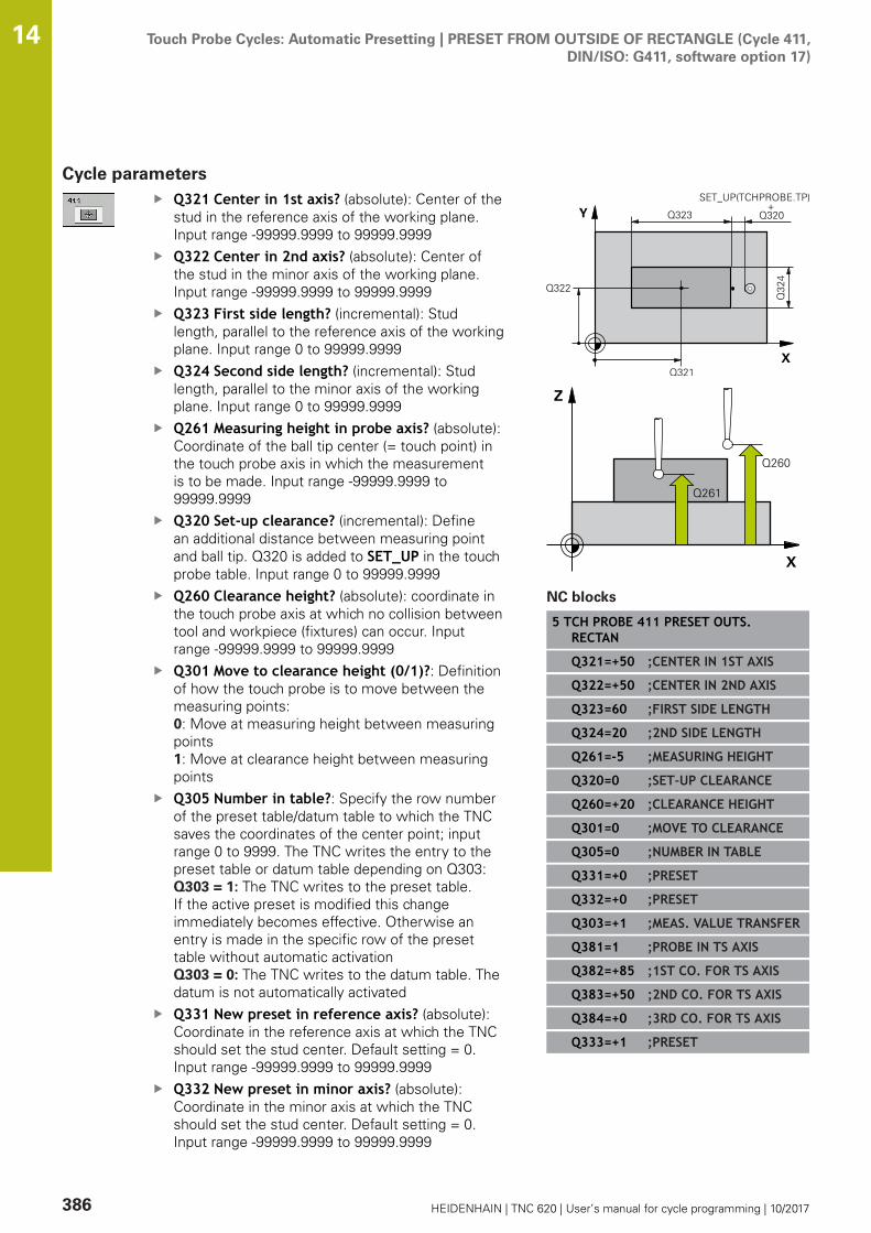
Touch Probe Cycles: Automatic Presetting | PRESET FROM OUTSIDE OF RECTANGLE (Cycle 411,DIN/ISO: G411, software option 17)
14
386 HEIDENHAIN | TNC 620 | User’s manual for cycle programming | 10/2017
Cycle parametersQ321 Center in 1st axis? (absolute): Center of thestud in the reference axis of the working plane.Input range -99999.9999 to 99999.9999Q322 Center in 2nd axis? (absolute): Center ofthe stud in the minor axis of the working plane.Input range -99999.9999 to 99999.9999Q323 First side length? (incremental): Studlength, parallel to the reference axis of the workingplane. Input range 0 to 99999.9999Q324 Second side length? (incremental): Studlength, parallel to the minor axis of the workingplane. Input range 0 to 99999.9999Q261 Measuring height in probe axis? (absolute):Coordinate of the ball tip center (= touch point) inthe touch probe axis in which the measurementis to be made. Input range -99999.9999 to99999.9999Q320 Set-up clearance? (incremental): Definean additional distance between measuring pointand ball tip. Q320 is added to SET_UP in the touchprobe table. Input range 0 to 99999.9999Q260 Clearance height? (absolute): coordinate inthe touch probe axis at which no collision betweentool and workpiece (fixtures) can occur. Inputrange -99999.9999 to 99999.9999Q301 Move to clearance height (0/1)?: Definitionof how the touch probe is to move between themeasuring points:0: Move at measuring height between measuringpoints1: Move at clearance height between measuringpointsQ305 Number in table?: Specify the row numberof the preset table/datum table to which the TNCsaves the coordinates of the center point; inputrange 0 to 9999. The TNC writes the entry to thepreset table or datum table depending on Q303: Q303 = 1: The TNC writes to the preset table.If the active preset is modified this changeimmediately becomes effective. Otherwise anentry is made in the specific row of the presettable without automatic activationQ303 = 0: The TNC writes to the datum table. Thedatum is not automatically activatedQ331 New preset in reference axis? (absolute):Coordinate in the reference axis at which the TNCshould set the stud center. Default setting = 0.Input range -99999.9999 to 99999.9999Q332 New preset in minor axis? (absolute):Coordinate in the minor axis at which the TNCshould set the stud center. Default setting = 0.Input range -99999.9999 to 99999.9999
NC blocks
5 TCH PROBE 411 PRESET OUTS.RECTAN
Q321=+50 ;CENTER IN 1ST AXIS
Q322=+50 ;CENTER IN 2ND AXIS
Q323=60 ;FIRST SIDE LENGTH
Q324=20 ;2ND SIDE LENGTH
Q261=-5 ;MEASURING HEIGHT
Q320=0 ;SET-UP CLEARANCE
Q260=+20 ;CLEARANCE HEIGHT
Q301=0 ;MOVE TO CLEARANCE
Q305=0 ;NUMBER IN TABLE
Q331=+0 ;PRESET
Q332=+0 ;PRESET
Q303=+1 ;MEAS. VALUE TRANSFER
Q381=1 ;PROBE IN TS AXIS
Q382=+85 ;1ST CO. FOR TS AXIS
Q383=+50 ;2ND CO. FOR TS AXIS
Q384=+0 ;3RD CO. FOR TS AXIS
Q333=+1 ;PRESET
Touch Probe Cycles: Automatic Presetting | PRESET FROM OUTSIDE OF RECTANGLE (Cycle 411,DIN/ISO: G411, software option 17)
14
HEIDENHAIN | TNC 620 | User’s manual for cycle programming | 10/2017 387
Q303 Meas. value transfer (0,1)?: Specifywhether the determined preset is to be saved inthe datum table or in the preset table:-1: Do not use! Is entered by the TNC whenold programs are read in (see "Characteristicscommon to all touch probe cycles for presetting",Page 370)0: Write the measured preset into the activedatum table. The reference system is the activeworkpiece coordinate system1: Write the measured preset into the preset table.The reference system is the machine coordinatesystem (REF system).Q381 Probe in TS axis? (0/1): Specify whetherthe TNC should also set the preset in the touchprobe axis:0: Do not set the preset in the touch probe axis1: Set the preset in the touch probe axisQ382 Probe TS axis: Coord. 1st axis? (absolute):Coordinate of the probe point in the reference axisof the working plane at which point the preset isto be set in the touch probe axis. Only effective ifQ381 = 1. Input range -99999.9999 to 99999.9999Q383 Probe TS axis: Coord. 2nd axis? (absolute):Coordinate of the probe point in the minor axisof the working plane at which point the preset isto be set in the touch probe axis. Only effective ifQ381 = 1. Input range -99999.9999 to 99999.9999Q384 Probe TS axis: Coord. 3rd axis? (absolute):Coordinate of the probe point in the touch probeaxis, at which point the preset is to be set in thetouch probe axis. Only effective if Q381 = 1. Inputrange -99999.9999 to 99999.9999Q333 New preset in TS axis? (absolute):Coordinate in the touch probe axis at which theTNC should set the preset. Default setting = 0.Input range -99999.9999 to 99999.9999

Touch Probe Cycles: Automatic Presetting | PRESET FROM INSIDE OF CIRCLE (Cycle 412, DIN/ISO: G412,software option 17)
14
388 HEIDENHAIN | TNC 620 | User’s manual for cycle programming | 10/2017
14.6 PRESET FROM INSIDE OF CIRCLE (Cycle412, DIN/ISO: G412, software option 17)
Cycle runTouch Probe Cycle 412 finds the center of a circular pocket (or of ahole) and defines its center as preset. If desired, the TNC can alsoenter the coordinates into a datum table or the preset table.1 Following the positioning logic, the TNC positions the touch
probe at rapid traverse (value from FMAX column) (see"Executing touch probe cycles", Page 339) to touch point 1. TheTNC calculates the touch points from the data in the cycle andthe safety clearance from the SET_UP column of the touchprobe table.
2 Then the touch probe moves to the entered measuring heightand runs the first probing process at the probing feed rate(column F). The TNC derives the probing direction automaticallyfrom the programmed starting angle.
3 Then the touch probe moves in a circular arc either at measuringheight or at clearance height to the next starting point 2 andprobes the second touch point.
4 The TNC positions the probe to starting point 3 and then tostarting point 4 to probe the third and fourth touch points.
5 Finally the TNC returns the touch probe to the clearance heightand processes the determined preset depending on the cycleparameters Q303 and Q305 (see "Characteristics common toall touch probe cycles for presetting", Page 370) and saves theactual values in the Q parameters listed below.
6 If desired, the TNC subsequently measures the preset in thetouch probe axis in a separate probing.
Parameter number Meaning
Q151 Actual value of center in reference axis
Q152 Actual value of center in minor axis
Q153 Actual value of diameter
Touch Probe Cycles: Automatic Presetting | PRESET FROM INSIDE OF CIRCLE (Cycle 412, DIN/ISO: G412,software option 17)
14
HEIDENHAIN | TNC 620 | User’s manual for cycle programming | 10/2017 389
Please note while programming:
The smaller the angle increment Q247, the lessaccurately the TNC can calculate the preset.Minimum input value: 5°Program a stepping angle to be less than 90°; inputrange -120° to 120°
NOTICEDanger of collision!
Cycles for coordinate transformation must not be active duringexecution of the touch probe cycles.
Do not activate the following cycles before using touch probecycles: Cycle 7 DATUM SHIFT,Cycle 8 MIRROR IMAGE, Cycle10 ROTATION,Cycle 11 SCALING and 26 AXIS-SPECIFICSCALINGReset any coordinate transformations beforehand
NOTICEDanger of collision!
To prevent a collision between the touch probe and theworkpiece, enter a low estimate for the nominal diameter of thepocket (or hole). If the dimensions of the pocket and the safetyclearance do not permit pre-positioning in the proximity of thetouch points, the TNC always starts probing from the center ofthe pocket. In this case the touch probe does not return to theclearance height between the four measuring points.
Positioning of the touch pointsBefore a cycle definition you must have programmed a toolcall to define the touch probe axis.
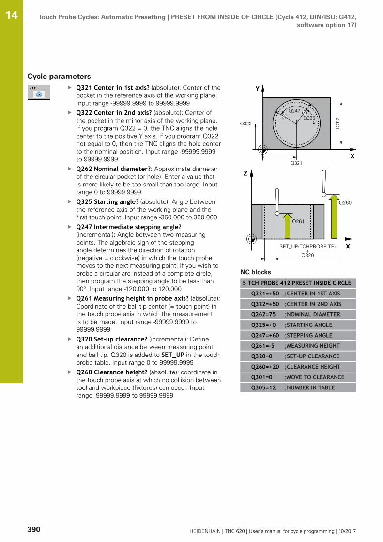
Touch Probe Cycles: Automatic Presetting | PRESET FROM INSIDE OF CIRCLE (Cycle 412, DIN/ISO: G412,software option 17)
14
390 HEIDENHAIN | TNC 620 | User’s manual for cycle programming | 10/2017
Cycle parametersQ321 Center in 1st axis? (absolute): Center of thepocket in the reference axis of the working plane.Input range -99999.9999 to 99999.9999Q322 Center in 2nd axis? (absolute): Center ofthe pocket in the minor axis of the working plane.If you program Q322 = 0, the TNC aligns the holecenter to the positive Y axis. If you program Q322not equal to 0, then the TNC aligns the hole centerto the nominal position. Input range -99999.9999to 99999.9999Q262 Nominal diameter?: Approximate diameterof the circular pocket (or hole). Enter a value thatis more likely to be too small than too large. Inputrange 0 to 99999.9999Q325 Starting angle? (absolute): Angle betweenthe reference axis of the working plane and thefirst touch point. Input range -360.000 to 360.000Q247 Intermediate stepping angle?(incremental): Angle between two measuringpoints. The algebraic sign of the steppingangle determines the direction of rotation(negative = clockwise) in which the touch probemoves to the next measuring point. If you wish toprobe a circular arc instead of a complete circle,then program the stepping angle to be less than90°. Input range -120.000 to 120.000Q261 Measuring height in probe axis? (absolute):Coordinate of the ball tip center (= touch point) inthe touch probe axis in which the measurementis to be made. Input range -99999.9999 to99999.9999Q320 Set-up clearance? (incremental): Definean additional distance between measuring pointand ball tip. Q320 is added to SET_UP in the touchprobe table. Input range 0 to 99999.9999Q260 Clearance height? (absolute): coordinate inthe touch probe axis at which no collision betweentool and workpiece (fixtures) can occur. Inputrange -99999.9999 to 99999.9999
NC blocks
5 TCH PROBE 412 PRESET INSIDE CIRCLE
Q321=+50 ;CENTER IN 1ST AXIS
Q322=+50 ;CENTER IN 2ND AXIS
Q262=75 ;NOMINAL DIAMETER
Q325=+0 ;STARTING ANGLE
Q247=+60 ;STEPPING ANGLE
Q261=-5 ;MEASURING HEIGHT
Q320=0 ;SET-UP CLEARANCE
Q260=+20 ;CLEARANCE HEIGHT
Q301=0 ;MOVE TO CLEARANCE
Q305=12 ;NUMBER IN TABLE

Touch Probe Cycles: Automatic Presetting | PRESET FROM INSIDE OF CIRCLE (Cycle 412, DIN/ISO: G412,software option 17)
14
HEIDENHAIN | TNC 620 | User’s manual for cycle programming | 10/2017 391
Q301 Move to clearance height (0/1)?: Definitionof how the touch probe is to move between themeasuring points:0: Move at measuring height between measuringpoints1: Move at clearance height between measuringpointsQ305 Number in table?: Specify the row numberof the preset table/datum table to which the TNCsaves the coordinates of the center point; inputrange 0 to 9999. The TNC writes the entry to thepreset table or datum table depending on Q303: Q303 = 1: The TNC writes to the preset table.If the active preset is modified this changeimmediately becomes effective. Otherwise anentry is made in the specific row of the presettable without automatic activationQ303 = 0: The TNC writes to the datum table. Thedatum is not automatically activatedQ331 New preset in reference axis? (absolute):Coordinate in the reference axis at which the TNCshould set the pocket center. Default setting = 0.Input range -99999.9999 to 99999.9999Q332 New preset in minor axis? (absolute):Coordinate in the minor axis at which the TNCshould set the pocket center. Default setting = 0.Input range -99999.9999 to 99999.9999Q303 Meas. value transfer (0,1)?: Specifywhether the determined preset is to be saved inthe datum table or in the preset table:-1: Do not use! Is entered by the TNC whenold programs are read in (see "Characteristicscommon to all touch probe cycles for presetting",Page 370)0: Write the measured preset into the activedatum table. The reference system is the activeworkpiece coordinate system1: Write the measured preset into the preset table.The reference system is the machine coordinatesystem (REF system).
Q331=+0 ;PRESET
Q332=+0 ;PRESET
Q303=+1 ;MEAS. VALUE TRANSFER
Q381=1 ;PROBE IN TS AXIS
Q382=+85 ;1ST CO. FOR TS AXIS
Q383=+50 ;2ND CO. FOR TS AXIS
Q384=+0 ;3RD CO. FOR TS AXIS
Q333=+1 ;PRESET
Q423=4 ;NO. OF PROBE POINTS
Q365=1 ;TYPE OF TRAVERSE
Touch Probe Cycles: Automatic Presetting | PRESET FROM INSIDE OF CIRCLE (Cycle 412, DIN/ISO: G412,software option 17)
14
392 HEIDENHAIN | TNC 620 | User’s manual for cycle programming | 10/2017
Q381 Probe in TS axis? (0/1): Specify whetherthe TNC should also set the preset in the touchprobe axis:0: Do not set the preset in the touch probe axis1: Set the preset in the touch probe axisQ382 Probe TS axis: Coord. 1st axis? (absolute):Coordinate of the probe point in the reference axisof the working plane at which point the preset isto be set in the touch probe axis. Only effective ifQ381 = 1. Input range -99999.9999 to 99999.9999Q383 Probe TS axis: Coord. 2nd axis? (absolute):Coordinate of the probe point in the minor axisof the working plane at which point the preset isto be set in the touch probe axis. Only effective ifQ381 = 1. Input range -99999.9999 to 99999.9999Q384 Probe TS axis: Coord. 3rd axis? (absolute):Coordinate of the probe point in the touch probeaxis, at which point the preset is to be set in thetouch probe axis. Only effective if Q381 = 1. Inputrange -99999.9999 to 99999.9999Q333 New preset in TS axis? (absolute):Coordinate in the touch probe axis at which theTNC should set the preset. Default setting = 0.Input range -99999.9999 to 99999.9999Q423 No. probe points in plane (4/3)?: Definewhether the TNC should measure the stud with 4or 3 probing points:4: Use 4 measuring points (standard setting)3: Use 3 measuring pointsQ365 Type of traverse? Line=0/arc=1: Definitionof the path function with which the tool is to movebetween the measuring points if "traverse toclearance height" (Q301=1) is active:0: Move in a straight line between machiningoperations1: Move in a circular arc on the pitch circlediameter between machining operations

Touch Probe Cycles: Automatic Presetting | PRESET FROM OUTSIDE OF CIRCLE (Cycle 413, DIN/ISO: G413,software option 17)
14
HEIDENHAIN | TNC 620 | User’s manual for cycle programming | 10/2017 393
14.7 PRESET FROM OUTSIDE OF CIRCLE(Cycle 413, DIN/ISO: G413, softwareoption 17)
Cycle runTouch Probe Cycle 413 finds the center of a circular stud anddefines it as preset. If desired, the TNC can also enter thecoordinates into a datum table or the preset table.1 Following the positioning logic, the TNC positions the touch
probe at rapid traverse (value from FMAX column) (see"Executing touch probe cycles", Page 339) to touch point 1. TheTNC calculates the touch points from the data in the cycle andthe safety clearance from the SET_UP column of the touchprobe table.
2 Then the touch probe moves to the entered measuring heightand runs the first probing process at the probing feed rate(column F). The TNC derives the probing direction automaticallyfrom the programmed starting angle.
3 Then the touch probe moves in a circular arc either at measuringheight or at clearance height to the next starting point 2 andprobes the second touch point.
4 The TNC positions the probe to starting point 3 and then tostarting point 4 to probe the third and fourth touch points.
5 Finally the TNC returns the touch probe to the clearance heightand processes the determined preset depending on the cycleparameters Q303 and Q305 (see "Characteristics common toall touch probe cycles for presetting", Page 370) and saves theactual values in the Q parameters listed below.
6 If desired, the TNC subsequently measures the preset in thetouch probe axis in a separate probing.
Parameter number Meaning
Q151 Actual value of center in reference axis
Q152 Actual value of center in minor axis
Q153 Actual value of diameter

Touch Probe Cycles: Automatic Presetting | PRESET FROM OUTSIDE OF CIRCLE (Cycle 413, DIN/ISO: G413,software option 17)
14
394 HEIDENHAIN | TNC 620 | User’s manual for cycle programming | 10/2017
Please note while programming:
The smaller the angle increment Q247, the lessaccurately the TNC can calculate the preset.Minimum input value: 5°Program a stepping angle to be less than 90°; inputrange -120° to 120°
NOTICEDanger of collision!
Cycles for coordinate transformation must not be active duringexecution of the touch probe cycles.
Do not activate the following cycles before using touch probecycles: Cycle 7 DATUM SHIFT,Cycle 8 MIRROR IMAGE, Cycle10 ROTATION,Cycle 11 SCALING and 26 AXIS-SPECIFICSCALINGReset any coordinate transformations beforehand
NOTICEDanger of collision!
To prevent a collision between touch probe and workpiece, entera high estimate for the nominal diameter of the stud.
Before a cycle definition you must have programmed a toolcall to define the touch probe axis.
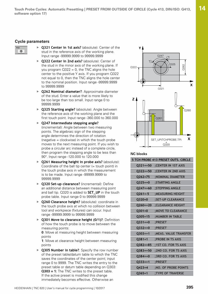
Touch Probe Cycles: Automatic Presetting | PRESET FROM OUTSIDE OF CIRCLE (Cycle 413, DIN/ISO: G413,software option 17)
14
HEIDENHAIN | TNC 620 | User’s manual for cycle programming | 10/2017 395
Cycle parametersQ321 Center in 1st axis? (absolute): Center of thestud in the reference axis of the working plane.Input range -99999.9999 to 99999.9999Q322 Center in 2nd axis? (absolute): Center ofthe stud in the minor axis of the working plane. Ifyou program Q322 = 0, the TNC aligns the holecenter to the positive Y axis. If you program Q322not equal to 0, then the TNC aligns the hole centerto the nominal position. Input range -99999.9999to 99999.9999Q262 Nominal diameter?: Approximate diameterof the stud. Enter a value that is more likely tobe too large than too small. Input range 0 to99999.9999Q325 Starting angle? (absolute): Angle betweenthe reference axis of the working plane and thefirst touch point. Input range -360.000 to 360.000Q247 Intermediate stepping angle?(incremental): Angle between two measuringpoints. The algebraic sign of the steppingangle determines the direction of rotation(negative = clockwise) in which the touch probemoves to the next measuring point. If you wish toprobe a circular arc instead of a complete circle,then program the stepping angle to be less than90°. Input range -120.000 to 120.000Q261 Measuring height in probe axis? (absolute):Coordinate of the ball tip center (= touch point) inthe touch probe axis in which the measurementis to be made. Input range -99999.9999 to99999.9999Q320 Set-up clearance? (incremental): Definean additional distance between measuring pointand ball tip. Q320 is added to SET_UP in the touchprobe table. Input range 0 to 99999.9999Q260 Clearance height? (absolute): coordinate inthe touch probe axis at which no collision betweentool and workpiece (fixtures) can occur. Inputrange -99999.9999 to 99999.9999Q301 Move to clearance height (0/1)?: Definitionof how the touch probe is to move between themeasuring points:0: Move at measuring height between measuringpoints1: Move at clearance height between measuringpointsQ305 Number in table?: Specify the row numberof the preset table/datum table to which the TNCsaves the coordinates of the center point; inputrange 0 to 9999. The TNC writes the entry to thepreset table or datum table depending on Q303: Q303 = 1: The TNC writes to the preset table.If the active preset is modified this changeimmediately becomes effective. Otherwise an
NC blocks
5 TCH PROBE 413 PRESET OUTS. CIRCLE
Q321=+50 ;CENTER IN 1ST AXIS
Q322=+50 ;CENTER IN 2ND AXIS
Q262=75 ;NOMINAL DIAMETER
Q325=+0 ;STARTING ANGLE
Q247=+60 ;STEPPING ANGLE
Q261=-5 ;MEASURING HEIGHT
Q320=0 ;SET-UP CLEARANCE
Q260=+20 ;CLEARANCE HEIGHT
Q301=0 ;MOVE TO CLEARANCE
Q305=15 ;NUMBER IN TABLE
Q331=+0 ;PRESET
Q332=+0 ;PRESET
Q303=+1 ;MEAS. VALUE TRANSFER
Q381=1 ;PROBE IN TS AXIS
Q382=+85 ;1ST CO. FOR TS AXIS
Q383=+50 ;2ND CO. FOR TS AXIS
Q384=+0 ;3RD CO. FOR TS AXIS
Q333=+1 ;PRESET
Q423=4 ;NO. OF PROBE POINTS
Q365=1 ;TYPE OF TRAVERSE
Touch Probe Cycles: Automatic Presetting | PRESET FROM OUTSIDE OF CIRCLE (Cycle 413, DIN/ISO: G413,software option 17)
14
396 HEIDENHAIN | TNC 620 | User’s manual for cycle programming | 10/2017
entry is made in the specific row of the presettable without automatic activationQ303 = 0: The TNC writes to the datum table. Thedatum is not automatically activatedQ331 New preset in reference axis? (absolute):Coordinate in the reference axis at which the TNCshould set the stud center. Default setting = 0.Input range -99999.9999 to 99999.9999Q332 New preset in minor axis? (absolute):Coordinate in the minor axis at which the TNCshould set the stud center. Default setting = 0.Input range -99999.9999 to 99999.9999Q303 Meas. value transfer (0,1)?: Specifywhether the determined preset is to be saved inthe datum table or in the preset table:-1: Do not use! Is entered by the TNC whenold programs are read in (see "Characteristicscommon to all touch probe cycles for presetting",Page 370)0: Write the measured preset into the activedatum table. The reference system is the activeworkpiece coordinate system1: Write the measured preset into the preset table.The reference system is the machine coordinatesystem (REF system).Q381 Probe in TS axis? (0/1): Specify whetherthe TNC should also set the preset in the touchprobe axis:0: Do not set the preset in the touch probe axis1: Set the preset in the touch probe axis
Touch Probe Cycles: Automatic Presetting | PRESET FROM OUTSIDE OF CIRCLE (Cycle 413, DIN/ISO: G413,software option 17)
14
HEIDENHAIN | TNC 620 | User’s manual for cycle programming | 10/2017 397
Q382 Probe TS axis: Coord. 1st axis? (absolute):Coordinate of the probe point in the reference axisof the working plane at which point the preset isto be set in the touch probe axis. Only effective ifQ381 = 1. Input range -99999.9999 to 99999.9999Q383 Probe TS axis: Coord. 2nd axis? (absolute):Coordinate of the probe point in the minor axisof the working plane at which point the preset isto be set in the touch probe axis. Only effective ifQ381 = 1. Input range -99999.9999 to 99999.9999Q384 Probe TS axis: Coord. 3rd axis? (absolute):Coordinate of the probe point in the touch probeaxis, at which point the preset is to be set in thetouch probe axis. Only effective if Q381 = 1. Inputrange -99999.9999 to 99999.9999Q333 New preset in TS axis? (absolute):Coordinate in the touch probe axis at which theTNC should set the preset. Default setting = 0.Input range -99999.9999 to 99999.9999Q423 No. probe points in plane (4/3)?: Definewhether the TNC should measure the stud with 4or 3 probing points:4: Use 4 measuring points (standard setting)3: Use 3 measuring pointsQ365 Type of traverse? Line=0/arc=1: Definitionof the path function with which the tool is to movebetween the measuring points if "traverse toclearance height" (Q301=1) is active:0: Move in a straight line between machiningoperations1: Move in a circular arc on the pitch circlediameter between machining operations

Touch Probe Cycles: Automatic Presetting | PRESET FROM OUTSIDE OF CORNER (Cycle 414, DIN/ISO: G414,software option 17)
14
398 HEIDENHAIN | TNC 620 | User’s manual for cycle programming | 10/2017
14.8 PRESET FROM OUTSIDE OF CORNER(Cycle 414, DIN/ISO: G414, softwareoption 17)
Cycle runTouch Probe Cycle 414 finds the intersection of two lines anddefines it as the preset. If desired, the TNC can also enter theintersection into a datum table or preset table.1 Following the positioning logic, the TNC positions the touch
probe at rapid traverse (value from FMAX column) (see"Executing touch probe cycles", Page 339) to touch point 1 (seefigure at upper right). The TNC offsets the touch probe by thesafety clearance in the direction opposite to the respectivetraverse direction.
2 Then the touch probe moves to the entered measuring heightand runs the first probing process at the probing feed rate(column F). The TNC derives the probing direction automaticallyfrom the programmed 3rd measuring point.
1 Then the touch probe moves to the next starting position 2 andfrom there probes the second position.
2 The TNC positions the probe to starting point 3 and then tostarting point 4 to probe the third and fourth touch points.
3 Finally the TNC returns the touch probe to the clearance heightand processes the determined preset depending on the cycleparameters Q303 and Q305 (see "Characteristics common toall touch probe cycles for presetting", Page 370) and saves thecoordinates of the determined corner in the Q parameters listedbelow.
4 If desired, the TNC subsequently measures the preset in thetouch probe axis in a separate probing.
Parameter number Meaning
Q151 Actual value of corner in reference axis
Q152 Actual value of corner in minor axis
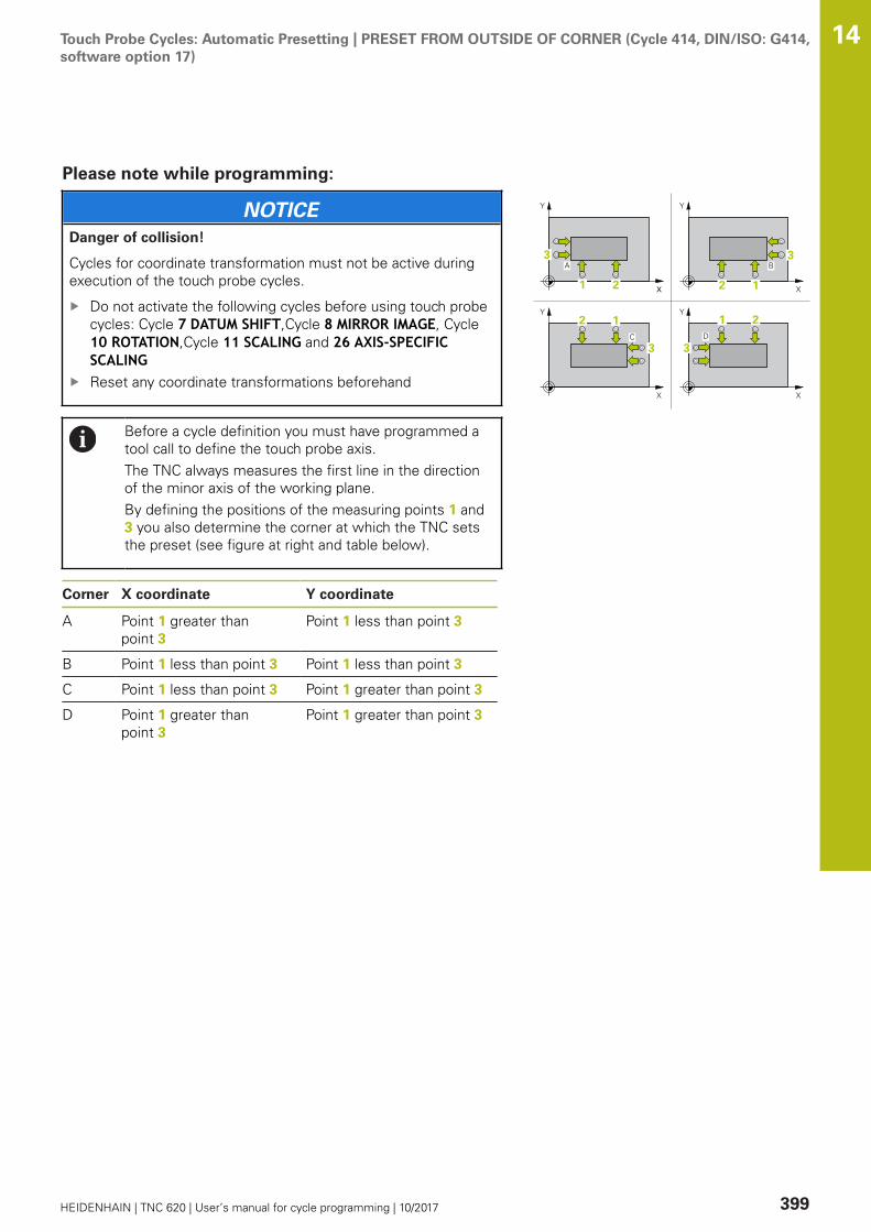
Touch Probe Cycles: Automatic Presetting | PRESET FROM OUTSIDE OF CORNER (Cycle 414, DIN/ISO: G414,software option 17)
14
HEIDENHAIN | TNC 620 | User’s manual for cycle programming | 10/2017 399
Please note while programming:
NOTICEDanger of collision!
Cycles for coordinate transformation must not be active duringexecution of the touch probe cycles.
Do not activate the following cycles before using touch probecycles: Cycle 7 DATUM SHIFT,Cycle 8 MIRROR IMAGE, Cycle10 ROTATION,Cycle 11 SCALING and 26 AXIS-SPECIFICSCALINGReset any coordinate transformations beforehand
Before a cycle definition you must have programmed atool call to define the touch probe axis.The TNC always measures the first line in the directionof the minor axis of the working plane.By defining the positions of the measuring points 1 and3 you also determine the corner at which the TNC setsthe preset (see figure at right and table below).
Corner X coordinate Y coordinate
A Point 1 greater thanpoint 3
Point 1 less than point 3
B Point 1 less than point 3 Point 1 less than point 3
C Point 1 less than point 3 Point 1 greater than point 3
D Point 1 greater thanpoint 3
Point 1 greater than point 3

Touch Probe Cycles: Automatic Presetting | PRESET FROM OUTSIDE OF CORNER (Cycle 414, DIN/ISO: G414,software option 17)
14
400 HEIDENHAIN | TNC 620 | User’s manual for cycle programming | 10/2017
Cycle parametersQ263 1st measuring point in 1st axis? (absolute):Coordinate of the first touch point in the referenceaxis of the working plane. Input range -99999.9999to 99999.9999Q264 1st measuring point in 2nd axis?(absolute): Coordinate of the first touch point inthe minor axis of the working plane. Input range-99999.9999 to 99999.9999Q326 Spacing in 1st axis? (incremental): Distancebetween the first and second measuring pointsin the reference axis of the working plane. Inputrange 0 to 99999.9999Q296 3rd measuring point in 1st axis? (absolute):Coordinate of the third touch point in the referenceaxis of the working plane. Input range -99999.9999to 99999.9999Q297 3rd measuring point in 2nd axis?(absolute): Coordinate of the third touch point inthe minor axis of the working plane. Input range-99999.9999 to 99999.9999Q327 Spacing in 2nd axis? (incremental): Distancebetween third and fourth measuring points in theminor axis of the working plane. Input range 0 to99999.9999Q261 Measuring height in probe axis? (absolute):Coordinate of the ball tip center (= touch point) inthe touch probe axis in which the measurementis to be made. Input range -99999.9999 to99999.9999Q320 Set-up clearance? (incremental): Definean additional distance between measuring pointand ball tip. Q320 is added to SET_UP in the touchprobe table. Input range 0 to 99999.9999Q260 Clearance height? (absolute): coordinate inthe touch probe axis at which no collision betweentool and workpiece (fixtures) can occur. Inputrange -99999.9999 to 99999.9999Q301 Move to clearance height (0/1)?: Definitionof how the touch probe is to move between themeasuring points:0: Move at measuring height between measuringpoints1: Move at clearance height between measuringpoints
NC blocks
5 TCH PROBE 414 PRESET INSIDECORNER
Q263=+37 ;1ST POINT 1ST AXIS
Q264=+7 ;1ST POINT 2ND AXIS
Q326=50 ;SPACING IN 1ST AXIS
Q296=+95 ;3RD PNT IN 1ST AXIS
Q297=+25 ;3RD PNT IN 2ND AXIS
Q327=45 ;SPACING IN 2ND AXIS
Q261=-5 ;MEASURING HEIGHT
Q320=0 ;SET-UP CLEARANCE
Q260=+20 ;CLEARANCE HEIGHT
Q301=0 ;MOVE TO CLEARANCE
Q304=0 ;BASIC ROTATION
Q305=7 ;NUMBER IN TABLE
Q331=+0 ;PRESET

Touch Probe Cycles: Automatic Presetting | PRESET FROM OUTSIDE OF CORNER (Cycle 414, DIN/ISO: G414,software option 17)
14
HEIDENHAIN | TNC 620 | User’s manual for cycle programming | 10/2017 401
Q304 Execute basic rotation (0/1)?: Definition ofwhether the TNC should compensate workpiecemisalignment with a basic rotation:0: Do not execute basic rotation1: Execute basic rotationQ305 Number in table?: Specify the row numberof the preset table/datum table to which the TNCsaves the coordinates of the corner; input range0 to 9999. The TNC writes the entry to the presettable or datum table depending on Q303: Q303 = 1: The TNC writes to the preset table.If the active preset is modified this changeimmediately becomes effective. Otherwise anentry is made in the specific row of the presettable without automatic activationQ303 = 0: The TNC writes to the datum table. Thedatum is not automatically activatedQ331 New preset in reference axis? (absolute):Coordinate in the reference axis at which the TNCshould set the corner. Default setting = 0. Inputrange -99999.9999 to 99999.9999Q332 New preset in minor axis? (absolute):Coordinate in the minor axis at which the TNCshould set the corner. Default setting = 0. Inputrange -99999.9999 to 99999.9999Q303 Meas. value transfer (0,1)?: Specifywhether the determined preset is to be saved inthe datum table or in the preset table:-1: Do not use! Is entered by the TNC whenold programs are read in (see "Characteristicscommon to all touch probe cycles for presetting",Page 370)0: Write the measured preset into the activedatum table. The reference system is the activeworkpiece coordinate system1: Write the measured preset into the preset table.The reference system is the machine coordinatesystem (REF system).Q381 Probe in TS axis? (0/1): Specify whetherthe TNC should also set the preset in the touchprobe axis:0: Do not set the preset in the touch probe axis1: Set the preset in the touch probe axis
Q332=+0 ;PRESET
Q303=+1 ;MEAS. VALUE TRANSFER
Q381=1 ;PROBE IN TS AXIS
Q382=+85 ;1ST CO. FOR TS AXIS
Q383=+50 ;2ND CO. FOR TS AXIS
Q384=+0 ;3RD CO. FOR TS AXIS
Q333=+1 ;PRESET
Touch Probe Cycles: Automatic Presetting | PRESET FROM OUTSIDE OF CORNER (Cycle 414, DIN/ISO: G414,software option 17)
14
402 HEIDENHAIN | TNC 620 | User’s manual for cycle programming | 10/2017
Q382 Probe TS axis: Coord. 1st axis? (absolute):Coordinate of the probe point in the reference axisof the working plane at which point the preset isto be set in the touch probe axis. Only effective ifQ381 = 1. Input range -99999.9999 to 99999.9999Q383 Probe TS axis: Coord. 2nd axis? (absolute):Coordinate of the probe point in the minor axisof the working plane at which point the preset isto be set in the touch probe axis. Only effective ifQ381 = 1. Input range -99999.9999 to 99999.9999Q384 Probe TS axis: Coord. 3rd axis? (absolute):Coordinate of the probe point in the touch probeaxis, at which point the preset is to be set in thetouch probe axis. Only effective if Q381 = 1. Inputrange -99999.9999 to 99999.9999Q333 New preset in TS axis? (absolute):Coordinate in the touch probe axis at which theTNC should set the preset. Default setting = 0.Input range -99999.9999 to 99999.9999
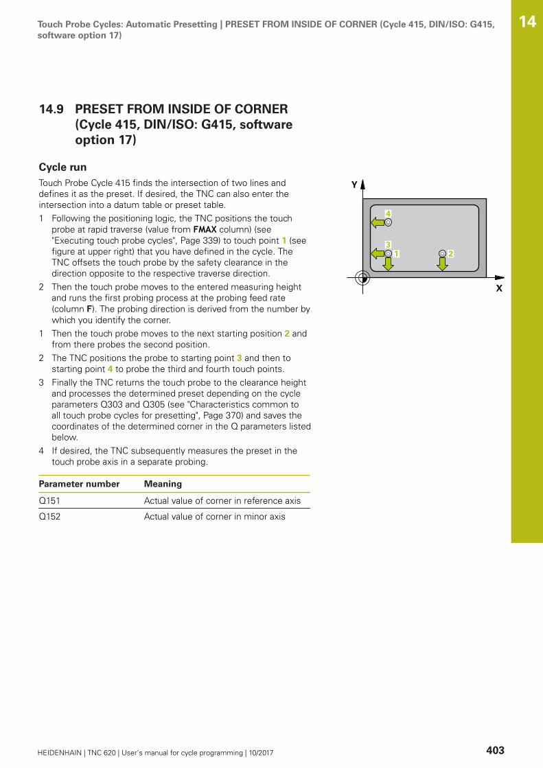
Touch Probe Cycles: Automatic Presetting | PRESET FROM INSIDE OF CORNER (Cycle 415, DIN/ISO: G415,software option 17)
14
HEIDENHAIN | TNC 620 | User’s manual for cycle programming | 10/2017 403
14.9 PRESET FROM INSIDE OF CORNER(Cycle 415, DIN/ISO: G415, softwareoption 17)
Cycle runTouch Probe Cycle 415 finds the intersection of two lines anddefines it as the preset. If desired, the TNC can also enter theintersection into a datum table or preset table.1 Following the positioning logic, the TNC positions the touch
probe at rapid traverse (value from FMAX column) (see"Executing touch probe cycles", Page 339) to touch point 1 (seefigure at upper right) that you have defined in the cycle. TheTNC offsets the touch probe by the safety clearance in thedirection opposite to the respective traverse direction.
2 Then the touch probe moves to the entered measuring heightand runs the first probing process at the probing feed rate(column F). The probing direction is derived from the number bywhich you identify the corner.
1 Then the touch probe moves to the next starting position 2 andfrom there probes the second position.
2 The TNC positions the probe to starting point 3 and then tostarting point 4 to probe the third and fourth touch points.
3 Finally the TNC returns the touch probe to the clearance heightand processes the determined preset depending on the cycleparameters Q303 and Q305 (see "Characteristics common toall touch probe cycles for presetting", Page 370) and saves thecoordinates of the determined corner in the Q parameters listedbelow.
4 If desired, the TNC subsequently measures the preset in thetouch probe axis in a separate probing.
Parameter number Meaning
Q151 Actual value of corner in reference axis
Q152 Actual value of corner in minor axis
Touch Probe Cycles: Automatic Presetting | PRESET FROM INSIDE OF CORNER (Cycle 415, DIN/ISO: G415,software option 17)
14
404 HEIDENHAIN | TNC 620 | User’s manual for cycle programming | 10/2017
Please note while programming:
NOTICEDanger of collision!
Cycles for coordinate transformation must not be active duringexecution of the touch probe cycles.
Do not activate the following cycles before using touch probecycles: Cycle 7 DATUM SHIFT,Cycle 8 MIRROR IMAGE, Cycle10 ROTATION,Cycle 11 SCALING and 26 AXIS-SPECIFICSCALINGReset any coordinate transformations beforehand
Before a cycle definition you must have programmed atool call to define the touch probe axis.The TNC always measures the first line in the directionof the minor axis of the working plane.
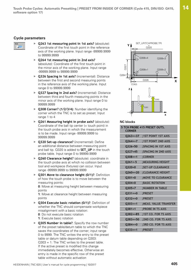
Touch Probe Cycles: Automatic Presetting | PRESET FROM INSIDE OF CORNER (Cycle 415, DIN/ISO: G415,software option 17)
14
HEIDENHAIN | TNC 620 | User’s manual for cycle programming | 10/2017 405
Cycle parametersQ263 1st measuring point in 1st axis? (absolute):Coordinate of the first touch point in the referenceaxis of the working plane. Input range -99999.9999to 99999.9999Q264 1st measuring point in 2nd axis?(absolute): Coordinate of the first touch point inthe minor axis of the working plane. Input range-99999.9999 to 99999.9999Q326 Spacing in 1st axis? (incremental): Distancebetween the first and second measuring pointsin the reference axis of the working plane. Inputrange 0 to 99999.9999Q327 Spacing in 2nd axis? (incremental): Distancebetween third and fourth measuring points in theminor axis of the working plane. Input range 0 to99999.9999Q308 Corner? (1/2/3/4): Number identifying thecorner which the TNC is to set as preset. Inputrange 1 to 4Q261 Measuring height in probe axis? (absolute):Coordinate of the ball tip center (= touch point) inthe touch probe axis in which the measurementis to be made. Input range -99999.9999 to99999.9999Q320 Set-up clearance? (incremental): Definean additional distance between measuring pointand ball tip. Q320 is added to SET_UP in the touchprobe table. Input range 0 to 99999.9999Q260 Clearance height? (absolute): coordinate inthe touch probe axis at which no collision betweentool and workpiece (fixtures) can occur. Inputrange -99999.9999 to 99999.9999Q301 Move to clearance height (0/1)?: Definitionof how the touch probe is to move between themeasuring points:0: Move at measuring height between measuringpoints1: Move at clearance height between measuringpointsQ304 Execute basic rotation (0/1)?: Definition ofwhether the TNC should compensate workpiecemisalignment with a basic rotation:0: Do not execute basic rotation1: Execute basic rotationQ305 Number in table?: Specify the row numberof the preset table/datum table to which the TNCsaves the coordinates of the corner; input range0 to 9999. The TNC writes the entry to the presettable or datum table depending on Q303: Q303 = 1: The TNC writes to the preset table.If the active preset is modified this changeimmediately becomes effective. Otherwise anentry is made in the specific row of the presettable without automatic activation
NC blocks
5 TCH PROBE 415 PRESET OUTS.CORNER
Q263=+37 ;1ST POINT 1ST AXIS
Q264=+7 ;1ST POINT 2ND AXIS
Q326=50 ;SPACING IN 1ST AXIS
Q327=45 ;SPACING IN 2ND AXIS
Q308=+1 ;CORNER
Q261=-5 ;MEASURING HEIGHT
Q320=0 ;SET-UP CLEARANCE
Q260=+20 ;CLEARANCE HEIGHT
Q301=0 ;MOVE TO CLEARANCE
Q304=0 ;BASIC ROTATION
Q305=7 ;NUMBER IN TABLE
Q331=+0 ;PRESET
Q332=+0 ;PRESET
Q303=+1 ;MEAS. VALUE TRANSFER
Q381=1 ;PROBE IN TS AXIS
Q382=+85 ;1ST CO. FOR TS AXIS
Q383=+50 ;2ND CO. FOR TS AXIS
Q384=+0 ;3RD CO. FOR TS AXIS
Q333=+1 ;PRESET
Touch Probe Cycles: Automatic Presetting | PRESET FROM INSIDE OF CORNER (Cycle 415, DIN/ISO: G415,software option 17)
14
406 HEIDENHAIN | TNC 620 | User’s manual for cycle programming | 10/2017
Q303 = 0: The TNC writes to the datum table. Thedatum is not automatically activatedQ331 New preset in reference axis? (absolute):Coordinate in the reference axis at which the TNCshould set the corner. Default setting = 0. Inputrange -99999.9999 to 99999.9999Q332 New preset in minor axis? (absolute):Coordinate in the minor axis at which the TNCshould set the corner. Default setting = 0. Inputrange -99999.9999 to 99999.9999Q303 Meas. value transfer (0,1)?: Specifywhether the determined preset is to be saved inthe datum table or in the preset table:-1: Do not use! Is entered by the TNC whenold programs are read in (see "Characteristicscommon to all touch probe cycles for presetting",Page 370)0: Write the measured preset into the activedatum table. The reference system is the activeworkpiece coordinate system1: Write the measured preset into the preset table.The reference system is the machine coordinatesystem (REF system).Q381 Probe in TS axis? (0/1): Specify whetherthe TNC should also set the preset in the touchprobe axis:0: Do not set the preset in the touch probe axis1: Set the preset in the touch probe axis
Touch Probe Cycles: Automatic Presetting | PRESET FROM INSIDE OF CORNER (Cycle 415, DIN/ISO: G415,software option 17)
14
HEIDENHAIN | TNC 620 | User’s manual for cycle programming | 10/2017 407
Q382 Probe TS axis: Coord. 1st axis? (absolute):Coordinate of the probe point in the reference axisof the working plane at which point the preset isto be set in the touch probe axis. Only effective ifQ381 = 1. Input range -99999.9999 to 99999.9999Q383 Probe TS axis: Coord. 2nd axis? (absolute):Coordinate of the probe point in the minor axisof the working plane at which point the preset isto be set in the touch probe axis. Only effective ifQ381 = 1. Input range -99999.9999 to 99999.9999Q384 Probe TS axis: Coord. 3rd axis? (absolute):Coordinate of the probe point in the touch probeaxis, at which point the preset is to be set in thetouch probe axis. Only effective if Q381 = 1. Inputrange -99999.9999 to 99999.9999Q333 New preset in TS axis? (absolute):Coordinate in the touch probe axis at which theTNC should set the preset. Default setting = 0.Input range -99999.9999 to 99999.9999
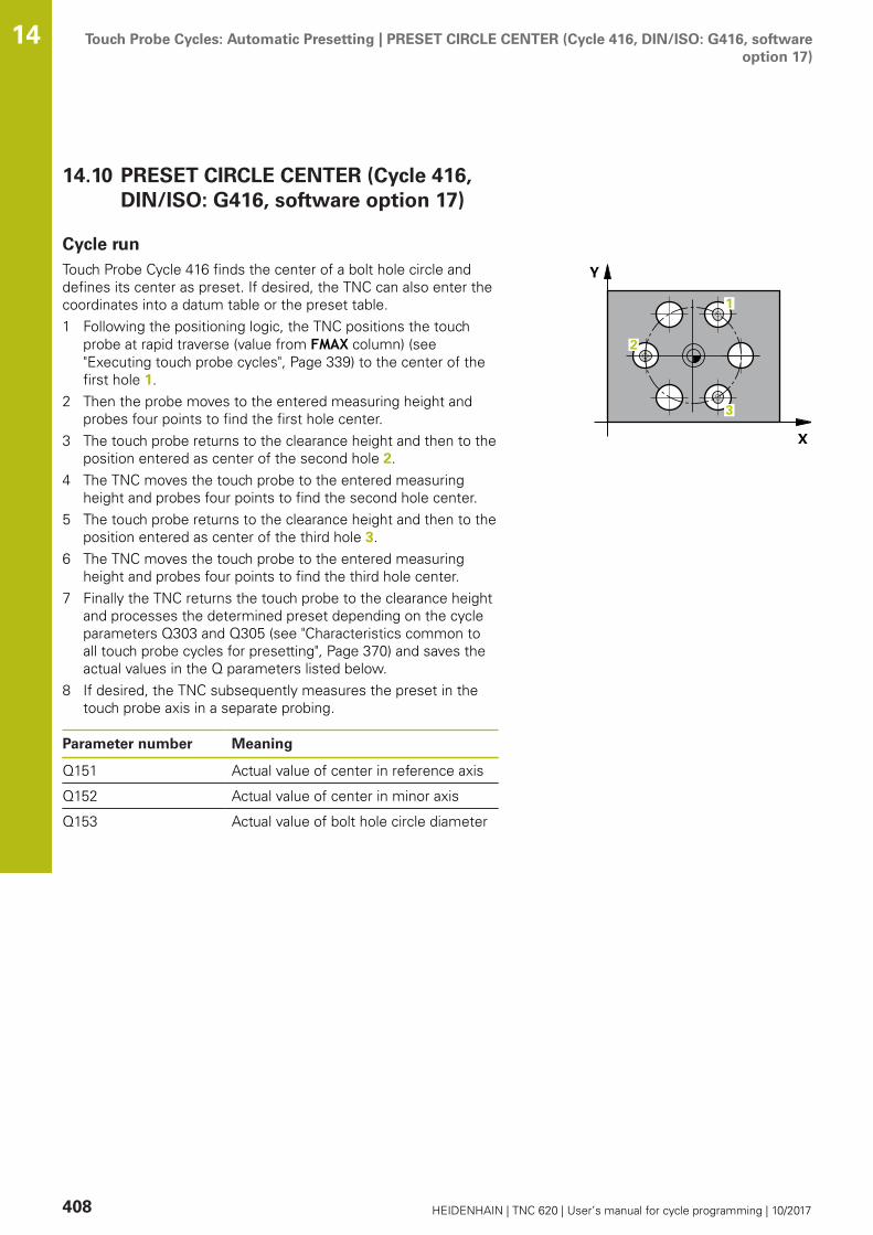
Touch Probe Cycles: Automatic Presetting | PRESET CIRCLE CENTER (Cycle 416, DIN/ISO: G416, softwareoption 17)
14
408 HEIDENHAIN | TNC 620 | User’s manual for cycle programming | 10/2017
14.10 PRESET CIRCLE CENTER (Cycle 416,DIN/ISO: G416, software option 17)
Cycle runTouch Probe Cycle 416 finds the center of a bolt hole circle anddefines its center as preset. If desired, the TNC can also enter thecoordinates into a datum table or the preset table.1 Following the positioning logic, the TNC positions the touch
probe at rapid traverse (value from FMAX column) (see"Executing touch probe cycles", Page 339) to the center of thefirst hole 1.
2 Then the probe moves to the entered measuring height andprobes four points to find the first hole center.
3 The touch probe returns to the clearance height and then to theposition entered as center of the second hole 2.
4 The TNC moves the touch probe to the entered measuringheight and probes four points to find the second hole center.
5 The touch probe returns to the clearance height and then to theposition entered as center of the third hole 3.
6 The TNC moves the touch probe to the entered measuringheight and probes four points to find the third hole center.
7 Finally the TNC returns the touch probe to the clearance heightand processes the determined preset depending on the cycleparameters Q303 and Q305 (see "Characteristics common toall touch probe cycles for presetting", Page 370) and saves theactual values in the Q parameters listed below.
8 If desired, the TNC subsequently measures the preset in thetouch probe axis in a separate probing.
Parameter number Meaning
Q151 Actual value of center in reference axis
Q152 Actual value of center in minor axis
Q153 Actual value of bolt hole circle diameter
Touch Probe Cycles: Automatic Presetting | PRESET CIRCLE CENTER (Cycle 416, DIN/ISO: G416, softwareoption 17)
14
HEIDENHAIN | TNC 620 | User’s manual for cycle programming | 10/2017 409
Please note while programming:
NOTICEDanger of collision!
Cycles for coordinate transformation must not be active duringexecution of the touch probe cycles.
Do not activate the following cycles before using touch probecycles: Cycle 7 DATUM SHIFT,Cycle 8 MIRROR IMAGE, Cycle10 ROTATION,Cycle 11 SCALING and 26 AXIS-SPECIFICSCALINGReset any coordinate transformations beforehand
Before a cycle definition you must have programmed atool call to define the touch probe axis.

Touch Probe Cycles: Automatic Presetting | PRESET CIRCLE CENTER (Cycle 416, DIN/ISO: G416, softwareoption 17)
14
410 HEIDENHAIN | TNC 620 | User’s manual for cycle programming | 10/2017
Cycle parametersQ273 Center in 1st axis (nom. value)? (absolute):Bolt hole circle center (nominal value) in thereference axis of the working plane. Input range-99999.9999 to 99999.9999Q274 Center in 2nd axis (nom. value)?(absolute): Bolt hole circle center (nominal value)in the minor axis of the working plane. Input range-99999.9999 to 99999.9999Q262 Nominal diameter?: Enter the approximatebolt hole circle diameter. The smaller the holediameter, the more exact the nominal diametermust be. Input range -0 to 99999.9999Q291 Polar coord. angle of 1st hole? (absolute):Polar coordinate angle of the first hole centerin the working plane. Input range -360.0000 to360.0000Q292 Polar coord. angle of 2nd hole? (absolute):Polar coordinate angle of the second hole centerin the working plane. Input range -360.0000 to360.0000Q292 Polar coord. angle of 3rd hole? (absolute):Polar coordinate angle of the third hole centerin the working plane. Input range -360.0000 to360.0000Q261 Measuring height in probe axis? (absolute):Coordinate of the ball tip center (= touch point) inthe touch probe axis in which the measurementis to be made. Input range -99999.9999 to99999.9999Q260 Clearance height? (absolute): coordinate inthe touch probe axis at which no collision betweentool and workpiece (fixtures) can occur. Inputrange -99999.9999 to 99999.9999Q305 Number in table?: Specify the row numberof the preset table/datum table to which the TNCsaves the coordinates of the center point; inputrange 0 to 9999. The TNC writes the entry to thepreset table or datum table depending on Q303: Q303 = 1: The TNC writes to the preset table.If the active preset is modified this changeimmediately becomes effective. Otherwise anentry is made in the specific row of the presettable without automatic activationQ303 = 0: The TNC writes to the datum table. Thedatum is not automatically activatedQ331 New preset in reference axis? (absolute):Coordinate in the reference axis at which theTNC should set the bolt hole circle center.Default setting = 0. Input range -99999.9999 to99999.9999Q332 New preset in minor axis? (absolute):Coordinate in the minor axis at which theTNC should set the bolt hole circle center.
NC blocks
5 TCH PROBE 416 PRESET CIRCLECENTER
Q273=+50 ;CENTER IN 1ST AXIS
Q274=+50 ;CENTER IN 2ND AXIS
Q262=90 ;NOMINAL DIAMETER
Q291=+34 ;ANGLE OF 1ST HOLE
Q292=+70 ;ANGLE OF 2ND HOLE
Q293=+210 ;ANGLE OF 3RD HOLE
Q261=-5 ;MEASURING HEIGHT
Q260=+20 ;CLEARANCE HEIGHT
Q305=12 ;NUMBER IN TABLE
Q331=+0 ;PRESET
Q332=+0 ;PRESET
Q303=+1 ;MEAS. VALUE TRANSFER
Q381=1 ;PROBE IN TS AXIS
Q382=+85 ;1ST CO. FOR TS AXIS
Q383=+50 ;2ND CO. FOR TS AXIS
Q384=+0 ;3RD CO. FOR TS AXIS
Q333=+1 ;PRESET
Q320=0 ;SET-UP CLEARANCE

Touch Probe Cycles: Automatic Presetting | PRESET CIRCLE CENTER (Cycle 416, DIN/ISO: G416, softwareoption 17)
14
HEIDENHAIN | TNC 620 | User’s manual for cycle programming | 10/2017 411
Default setting = 0. Input range -99999.9999 to99999.9999Q303 Meas. value transfer (0,1)?: Specifywhether the determined preset is to be saved inthe datum table or in the preset table:-1: Do not use! Is entered by the TNC whenold programs are read in (see "Characteristicscommon to all touch probe cycles for presetting",Page 370)0: Write the measured preset into the activedatum table. The reference system is the activeworkpiece coordinate system1: Write the measured preset into the preset table.The reference system is the machine coordinatesystem (REF system).Q381 Probe in TS axis? (0/1): Specify whetherthe TNC should also set the preset in the touchprobe axis:0: Do not set the preset in the touch probe axis1: Set the preset in the touch probe axisQ382 Probe TS axis: Coord. 1st axis? (absolute):Coordinate of the probe point in the reference axisof the working plane at which point the preset isto be set in the touch probe axis. Only effective ifQ381 = 1. Input range -99999.9999 to 99999.9999Q383 Probe TS axis: Coord. 2nd axis? (absolute):Coordinate of the probe point in the minor axisof the working plane at which point the preset isto be set in the touch probe axis. Only effective ifQ381 = 1. Input range -99999.9999 to 99999.9999Q384 Probe TS axis: Coord. 3rd axis? (absolute):Coordinate of the probe point in the touch probeaxis, at which point the preset is to be set in thetouch probe axis. Only effective if Q381 = 1. Inputrange -99999.9999 to 99999.9999Q333 New preset in TS axis? (absolute):Coordinate in the touch probe axis at which theTNC should set the preset. Default setting = 0.Input range -99999.9999 to 99999.9999Q320 Set-up clearance? (incremental): Additionaldistance between measuring point and ball tip.Q320 is added to SET_UP (touch probe table), andis only effective when the preset is probed in thetouch probe axis. Input range 0 to 99999.9999
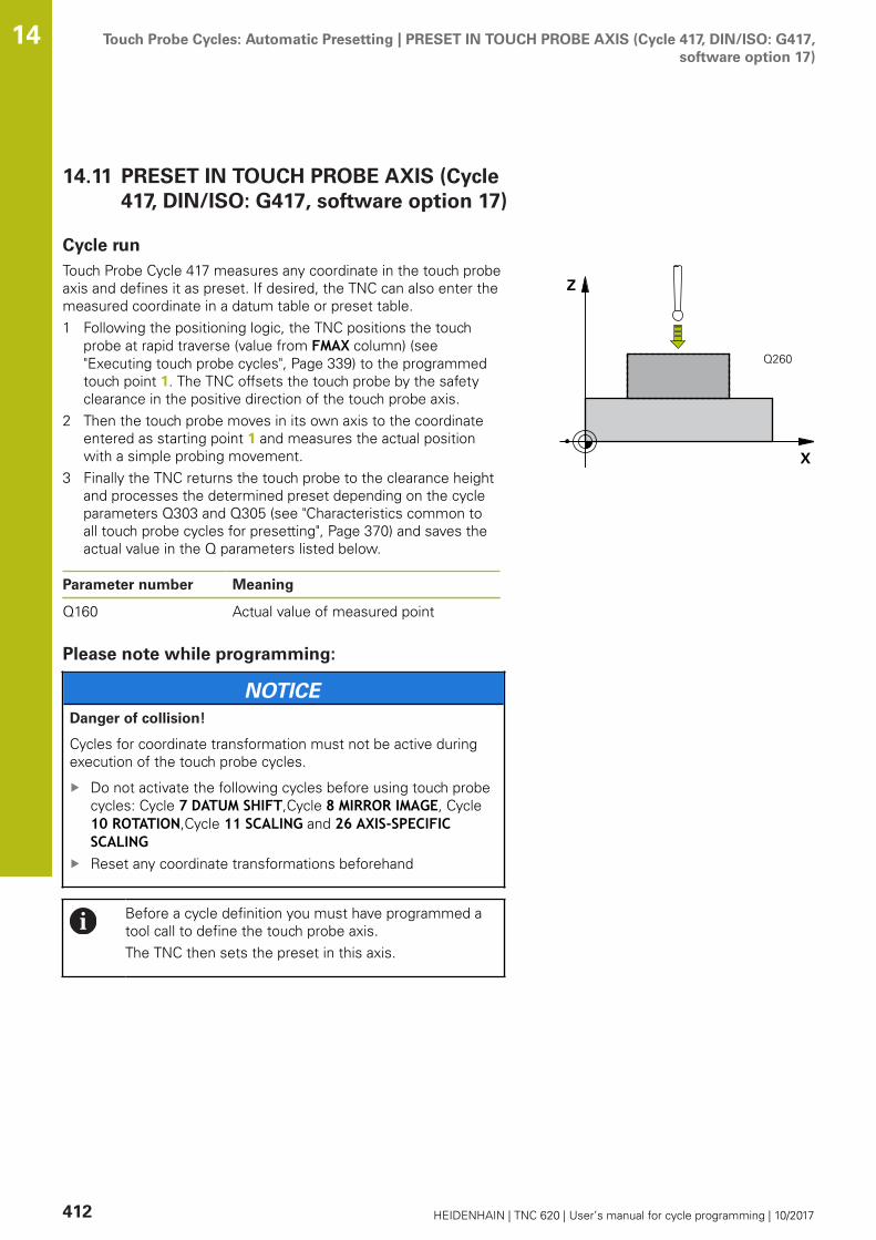
Touch Probe Cycles: Automatic Presetting | PRESET IN TOUCH PROBE AXIS (Cycle 417, DIN/ISO: G417,software option 17)
14
412 HEIDENHAIN | TNC 620 | User’s manual for cycle programming | 10/2017
14.11 PRESET IN TOUCH PROBE AXIS (Cycle417, DIN/ISO: G417, software option 17)
Cycle runTouch Probe Cycle 417 measures any coordinate in the touch probeaxis and defines it as preset. If desired, the TNC can also enter themeasured coordinate in a datum table or preset table.1 Following the positioning logic, the TNC positions the touch
probe at rapid traverse (value from FMAX column) (see"Executing touch probe cycles", Page 339) to the programmedtouch point 1. The TNC offsets the touch probe by the safetyclearance in the positive direction of the touch probe axis.
2 Then the touch probe moves in its own axis to the coordinateentered as starting point 1 and measures the actual positionwith a simple probing movement.
3 Finally the TNC returns the touch probe to the clearance heightand processes the determined preset depending on the cycleparameters Q303 and Q305 (see "Characteristics common toall touch probe cycles for presetting", Page 370) and saves theactual value in the Q parameters listed below.
Parameter number Meaning
Q160 Actual value of measured point
Please note while programming:
NOTICEDanger of collision!
Cycles for coordinate transformation must not be active duringexecution of the touch probe cycles.
Do not activate the following cycles before using touch probecycles: Cycle 7 DATUM SHIFT,Cycle 8 MIRROR IMAGE, Cycle10 ROTATION,Cycle 11 SCALING and 26 AXIS-SPECIFICSCALINGReset any coordinate transformations beforehand
Before a cycle definition you must have programmed atool call to define the touch probe axis.The TNC then sets the preset in this axis.
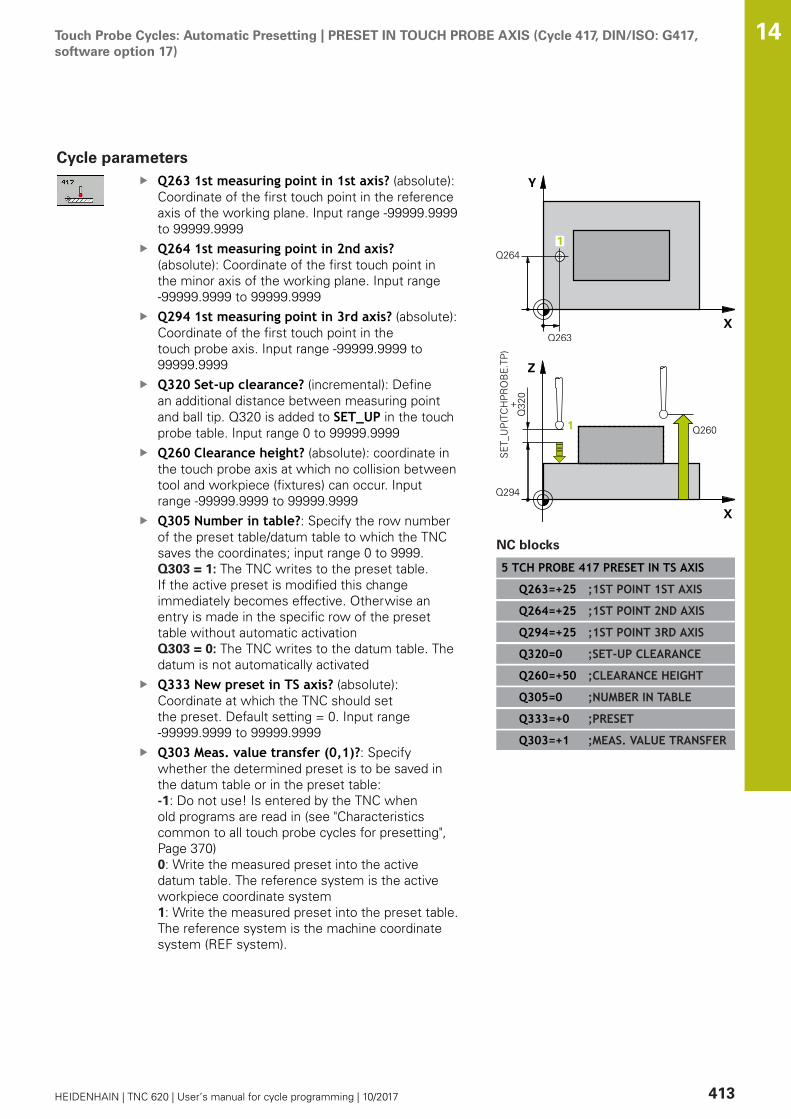
Touch Probe Cycles: Automatic Presetting | PRESET IN TOUCH PROBE AXIS (Cycle 417, DIN/ISO: G417,software option 17)
14
HEIDENHAIN | TNC 620 | User’s manual for cycle programming | 10/2017 413
Cycle parametersQ263 1st measuring point in 1st axis? (absolute):Coordinate of the first touch point in the referenceaxis of the working plane. Input range -99999.9999to 99999.9999Q264 1st measuring point in 2nd axis?(absolute): Coordinate of the first touch point inthe minor axis of the working plane. Input range-99999.9999 to 99999.9999Q294 1st measuring point in 3rd axis? (absolute):Coordinate of the first touch point in thetouch probe axis. Input range -99999.9999 to99999.9999Q320 Set-up clearance? (incremental): Definean additional distance between measuring pointand ball tip. Q320 is added to SET_UP in the touchprobe table. Input range 0 to 99999.9999Q260 Clearance height? (absolute): coordinate inthe touch probe axis at which no collision betweentool and workpiece (fixtures) can occur. Inputrange -99999.9999 to 99999.9999Q305 Number in table?: Specify the row numberof the preset table/datum table to which the TNCsaves the coordinates; input range 0 to 9999. Q303 = 1: The TNC writes to the preset table.If the active preset is modified this changeimmediately becomes effective. Otherwise anentry is made in the specific row of the presettable without automatic activation Q303 = 0: The TNC writes to the datum table. Thedatum is not automatically activatedQ333 New preset in TS axis? (absolute):Coordinate at which the TNC should setthe preset. Default setting = 0. Input range-99999.9999 to 99999.9999Q303 Meas. value transfer (0,1)?: Specifywhether the determined preset is to be saved inthe datum table or in the preset table:-1: Do not use! Is entered by the TNC whenold programs are read in (see "Characteristicscommon to all touch probe cycles for presetting",Page 370)0: Write the measured preset into the activedatum table. The reference system is the activeworkpiece coordinate system1: Write the measured preset into the preset table.The reference system is the machine coordinatesystem (REF system).
NC blocks
5 TCH PROBE 417 PRESET IN TS AXIS
Q263=+25 ;1ST POINT 1ST AXIS
Q264=+25 ;1ST POINT 2ND AXIS
Q294=+25 ;1ST POINT 3RD AXIS
Q320=0 ;SET-UP CLEARANCE
Q260=+50 ;CLEARANCE HEIGHT
Q305=0 ;NUMBER IN TABLE
Q333=+0 ;PRESET
Q303=+1 ;MEAS. VALUE TRANSFER

Touch Probe Cycles: Automatic Presetting | PRESET AT CENTER OF 4 HOLES (Cycle 418, DIN/ISO: G418,software option 17)
14
414 HEIDENHAIN | TNC 620 | User’s manual for cycle programming | 10/2017
14.12 PRESET AT CENTER OF 4 HOLES (Cycle418, DIN/ISO: G418, software option 17)
Cycle runTouch Probe Cycle 418 calculates the intersection of the linesconnecting opposite holes and sets the preset at the intersection.If desired, the TNC can also enter the intersection into a datumtable or preset table.1 Following the positioning logic, the TNC positions the touch
probe at rapid traverse (value from FMAX column) (see"Executing touch probe cycles", Page 339) to the center of thefirst hole 1.
2 Then the probe moves to the entered measuring height andprobes four points to find the first hole center.
3 The touch probe returns to the clearance height and then to theposition entered as center of the second hole 2.
4 The TNC moves the touch probe to the entered measuringheight and probes four points to find the second hole center.
5 The TNC repeats steps 3 and 4 for holes 3 and 4.6 Finally the TNC returns the touch probe to the clearance height
and processes the determined preset depending on the cycleparameters Q303 and Q305 (see "Characteristics commonto all touch probe cycles for presetting", Page 370). The TNCcalculates the preset as the intersection of the lines connectingthe centers of holes 1/3 and 2/4 and saves the actual values inthe Q parameters listed below.
7 If desired, the TNC subsequently measures the preset in thetouch probe axis in a separate probing.
Parameter number Meaning
Q151 Actual value of intersection point inreference axis
Q152 Actual value of intersection point inminor axis

Touch Probe Cycles: Automatic Presetting | PRESET AT CENTER OF 4 HOLES (Cycle 418, DIN/ISO: G418,software option 17)
14
HEIDENHAIN | TNC 620 | User’s manual for cycle programming | 10/2017 415
Please note while programming:
NOTICEDanger of collision!
Cycles for coordinate transformation must not be active duringexecution of the touch probe cycles.
Do not activate the following cycles before using touch probecycles: Cycle 7 DATUM SHIFT,Cycle 8 MIRROR IMAGE, Cycle10 ROTATION,Cycle 11 SCALING and 26 AXIS-SPECIFICSCALINGReset any coordinate transformations beforehand
Before a cycle definition you must have programmed atool call to define the touch probe axis.

Touch Probe Cycles: Automatic Presetting | PRESET AT CENTER OF 4 HOLES (Cycle 418, DIN/ISO: G418,software option 17)
14
416 HEIDENHAIN | TNC 620 | User’s manual for cycle programming | 10/2017
Cycle parametersQ268 1st hole: center in 1st axis? (absolute):Center of the first hole in the reference axis ofthe working plane. Input range -99999.9999 to99999.9999Q269 1st hole: center in 2nd axis? (absolute):Center of the first hole in the minor axis ofthe working plane. Input range -99999.9999 to99999.9999Q270 2nd hole: center in 1st axis? (absolute):Center of the second hole in the reference axisof the working plane. Input range -99999.9999 to99999.9999Q271 2nd hole: center in 2nd axis? (absolute):Center of the second hole in the minor axis ofthe working plane. Input range -99999.9999 to99999.9999Q316 3rd hole: Center in 1st axis? (absolute):Center of the third hole in the reference axis ofthe working plane. Input range -99999.9999 to99999.9999Q317 3rd hole: Center in 2nd axis? (absolute):Center of the third hole in the minor axis ofthe working plane. Input range -99999.9999 to99999.9999Q318 4th hole: Center in 1st axis? (absolute):Center of the fourth hole in the reference axis ofthe working plane. Input range -99999.9999 to99999.9999Q319 4th hole: Center in 2nd axis? (absolute):Center of the fourth hole in the minor axis ofthe working plane. Input range -99999.9999 to99999.9999Q261 Measuring height in probe axis? (absolute):Coordinate of the ball tip center (= touch point) inthe touch probe axis in which the measurementis to be made. Input range -99999.9999 to99999.9999Q260 Clearance height? (absolute): coordinate inthe touch probe axis at which no collision betweentool and workpiece (fixtures) can occur. Inputrange -99999.9999 to 99999.9999Q305 Number in table?: Specify the row numberof the preset table/datum table to which the TNCsaves the coordinates of the intersection of theconnecting lines; input range 0 to 9999. Q303 = 1: The TNC writes to the preset table.If the active preset is modified this changeimmediately becomes effective. Otherwise anentry is made in the specific row of the presettable without automatic activationQ303 = 0: The TNC writes to the datum table. Thedatum is not automatically activated
NC blocks
5 TCH PROBE 418 PRESET FROM 4HOLES
Q268=+20 ;1ST CENTER 1ST AXIS
Q269=+25 ;1ST CENTER 2ND AXIS
Q270=+150 ;2ND CENTER 1ST AXIS
Q271=+25 ;2ND CENTER 2ND AXIS
Q316=+150 ;3RD CENTER 1ST AXIS
Q317=+85 ;3RD CENTER 2ND AXIS
Q318=+22 ;4TH CENTER 1ST AXIS
Q319=+80 ;4TH CENTER 2ND AXIS
Q261=-5 ;MEASURING HEIGHT
Q260=+10 ;CLEARANCE HEIGHT
Q305=12 ;NUMBER IN TABLE
Q331=+0 ;PRESET
Q332=+0 ;PRESET
Q303=+1 ;MEAS. VALUE TRANSFER
Q381=1 ;PROBE IN TS AXIS
Q382=+85 ;1ST CO. FOR TS AXIS
Q383=+50 ;2ND CO. FOR TS AXIS
Q384=+0 ;3RD CO. FOR TS AXIS
Q333=+0 ;PRESET
Touch Probe Cycles: Automatic Presetting | PRESET AT CENTER OF 4 HOLES (Cycle 418, DIN/ISO: G418,software option 17)
14
HEIDENHAIN | TNC 620 | User’s manual for cycle programming | 10/2017 417
Q331 New preset in reference axis? (absolute):Coordinate in the reference axis at which the TNCshould set the intersection of the connecting lines.Default setting = 0. Input range -99999.9999 to99999.9999Q332 New preset in minor axis? (absolute):Coordinate in the minor axis at which the TNCshould set the intersection of the connecting lines.Default setting = 0. Input range -99999.9999 to99999.9999Q303 Meas. value transfer (0,1)?: Specifywhether the determined preset is to be saved inthe datum table or in the preset table:-1: Do not use! Is entered by the TNC whenold programs are read in (see "Characteristicscommon to all touch probe cycles for presetting",Page 370)0: Write the measured preset into the activedatum table. The reference system is the activeworkpiece coordinate system1: Write the measured preset into the preset table.The reference system is the machine coordinatesystem (REF system).Q381 Probe in TS axis? (0/1): Specify whetherthe TNC should also set the preset in the touchprobe axis:0: Do not set the preset in the touch probe axis1: Set the preset in the touch probe axisQ382 Probe TS axis: Coord. 1st axis? (absolute):Coordinate of the probe point in the reference axisof the working plane at which point the preset isto be set in the touch probe axis. Only effective ifQ381 = 1. Input range -99999.9999 to 99999.9999Q383 Probe TS axis: Coord. 2nd axis? (absolute):Coordinate of the probe point in the minor axisof the working plane at which point the preset isto be set in the touch probe axis. Only effective ifQ381 = 1. Input range -99999.9999 to 99999.9999Q384 Probe TS axis: Coord. 3rd axis? (absolute):Coordinate of the probe point in the touch probeaxis, at which point the preset is to be set in thetouch probe axis. Only effective if Q381 = 1. Inputrange -99999.9999 to 99999.9999Q333 New preset in TS axis? (absolute):Coordinate in the touch probe axis at which theTNC should set the preset. Default setting = 0.Input range -99999.9999 to 99999.9999
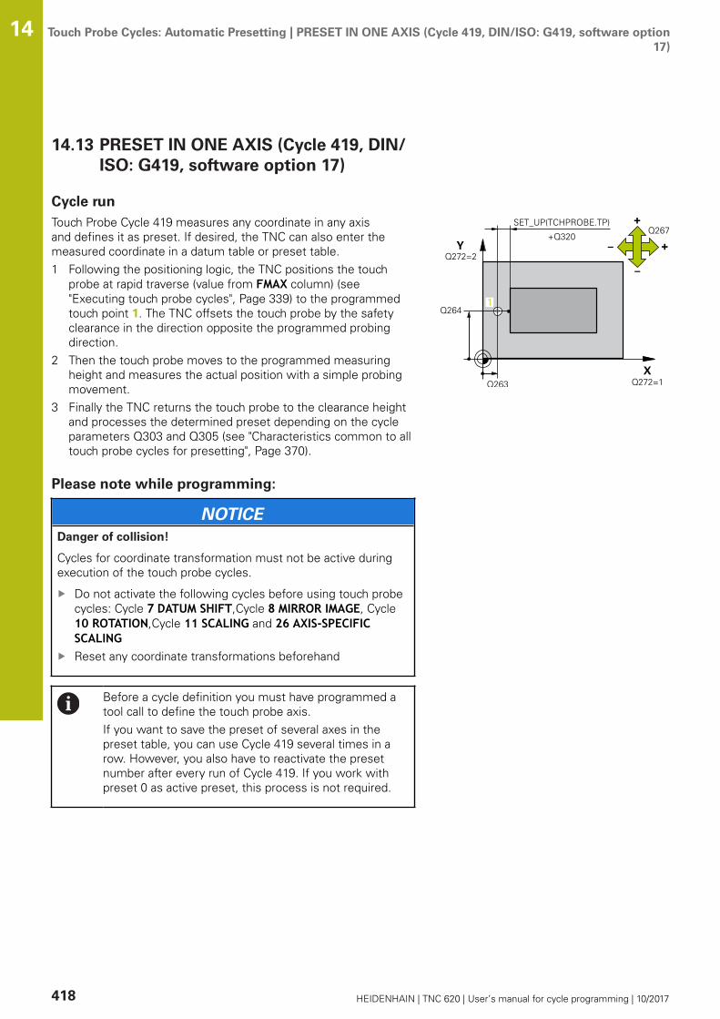
Touch Probe Cycles: Automatic Presetting | PRESET IN ONE AXIS (Cycle 419, DIN/ISO: G419, software option17)
14
418 HEIDENHAIN | TNC 620 | User’s manual for cycle programming | 10/2017
14.13 PRESET IN ONE AXIS (Cycle 419, DIN/ISO: G419, software option 17)
Cycle runTouch Probe Cycle 419 measures any coordinate in any axisand defines it as preset. If desired, the TNC can also enter themeasured coordinate in a datum table or preset table.1 Following the positioning logic, the TNC positions the touch
probe at rapid traverse (value from FMAX column) (see"Executing touch probe cycles", Page 339) to the programmedtouch point 1. The TNC offsets the touch probe by the safetyclearance in the direction opposite the programmed probingdirection.
2 Then the touch probe moves to the programmed measuringheight and measures the actual position with a simple probingmovement.
3 Finally the TNC returns the touch probe to the clearance heightand processes the determined preset depending on the cycleparameters Q303 and Q305 (see "Characteristics common to alltouch probe cycles for presetting", Page 370).
Please note while programming:
NOTICEDanger of collision!
Cycles for coordinate transformation must not be active duringexecution of the touch probe cycles.
Do not activate the following cycles before using touch probecycles: Cycle 7 DATUM SHIFT,Cycle 8 MIRROR IMAGE, Cycle10 ROTATION,Cycle 11 SCALING and 26 AXIS-SPECIFICSCALINGReset any coordinate transformations beforehand
Before a cycle definition you must have programmed atool call to define the touch probe axis.If you want to save the preset of several axes in thepreset table, you can use Cycle 419 several times in arow. However, you also have to reactivate the presetnumber after every run of Cycle 419. If you work withpreset 0 as active preset, this process is not required.

Touch Probe Cycles: Automatic Presetting | PRESET IN ONE AXIS (Cycle 419, DIN/ISO: G419, software option17)
14
HEIDENHAIN | TNC 620 | User’s manual for cycle programming | 10/2017 419
Cycle parametersQ263 1st measuring point in 1st axis? (absolute):Coordinate of the first touch point in the referenceaxis of the working plane. Input range -99999.9999to 99999.9999Q264 1st measuring point in 2nd axis?(absolute): Coordinate of the first touch point inthe minor axis of the working plane. Input range-99999.9999 to 99999.9999Q261 Measuring height in probe axis? (absolute):Coordinate of the ball tip center (= touch point) inthe touch probe axis in which the measurementis to be made. Input range -99999.9999 to99999.9999Q320 Set-up clearance? (incremental): Definean additional distance between measuring pointand ball tip. Q320 is added to SET_UP in the touchprobe table. Input range 0 to 99999.9999Q260 Clearance height? (absolute): coordinate inthe touch probe axis at which no collision betweentool and workpiece (fixtures) can occur. Inputrange -99999.9999 to 99999.9999Q272 Meas. axis (1/2/3, 1=ref. axis)?: Axis inwhich the measurement is to be made:1: Reference axis = measuring axis2: Minor axis = measuring axis3: Touch probe axis = measuring axis
Axis assignment
Active touch probeaxis: Q272= 3
Correspondingreference axis:Q272= 1
Correspond-ing minor axis:Q272= 2
Z X Y
Y Z X
X Y Z
Q267 Trav. direction 1 (+1=+ / -1=-)?: Directionin which the probe is to approach the workpiece:-1: Negative traverse direction+1: Positive traverse direction
NC blocks
5 TCH PROBE 419 PRESET IN ONE AXIS
Q263=+25 ;1ST POINT 1ST AXIS
Q264=+25 ;1ST POINT 2ND AXIS
Q261=+25 ;MEASURING HEIGHT
Q320=0 ;SET-UP CLEARANCE
Q260=+50 ;CLEARANCE HEIGHT
Q272=+1 ;MEASURING AXIS
Q267=+1 ;TRAVERSE DIRECTION
Q305=0 ;NUMBER IN TABLE
Q333=+0 ;PRESET
Q303=+1 ;MEAS. VALUE TRANSFER
Touch Probe Cycles: Automatic Presetting | PRESET IN ONE AXIS (Cycle 419, DIN/ISO: G419, software option17)
14
420 HEIDENHAIN | TNC 620 | User’s manual for cycle programming | 10/2017
Q305 Number in table?: Specify the row numberof the preset table/datum table to which the TNCsaves the coordinates; input range 0 to 9999. Q303 = 1: The TNC writes to the preset table.If the active preset is modified this changeimmediately becomes effective. Otherwise anentry is made in the specific row of the presettable without automatic activation Q303 = 0: The TNC writes to the datum table. Thedatum is not automatically activatedQ333 New preset in TS axis? (absolute):Coordinate at which the TNC should setthe preset. Default setting = 0. Input range-99999.9999 to 99999.9999Q303 Meas. value transfer (0,1)?: Specifywhether the determined preset is to be saved inthe datum table or in the preset table:-1: Do not use! Is entered by the TNC whenold programs are read in (see "Characteristicscommon to all touch probe cycles for presetting",Page 370)0: Write the measured preset into the activedatum table. The reference system is the activeworkpiece coordinate system1: Write the measured preset into the preset table.The reference system is the machine coordinatesystem (REF system).
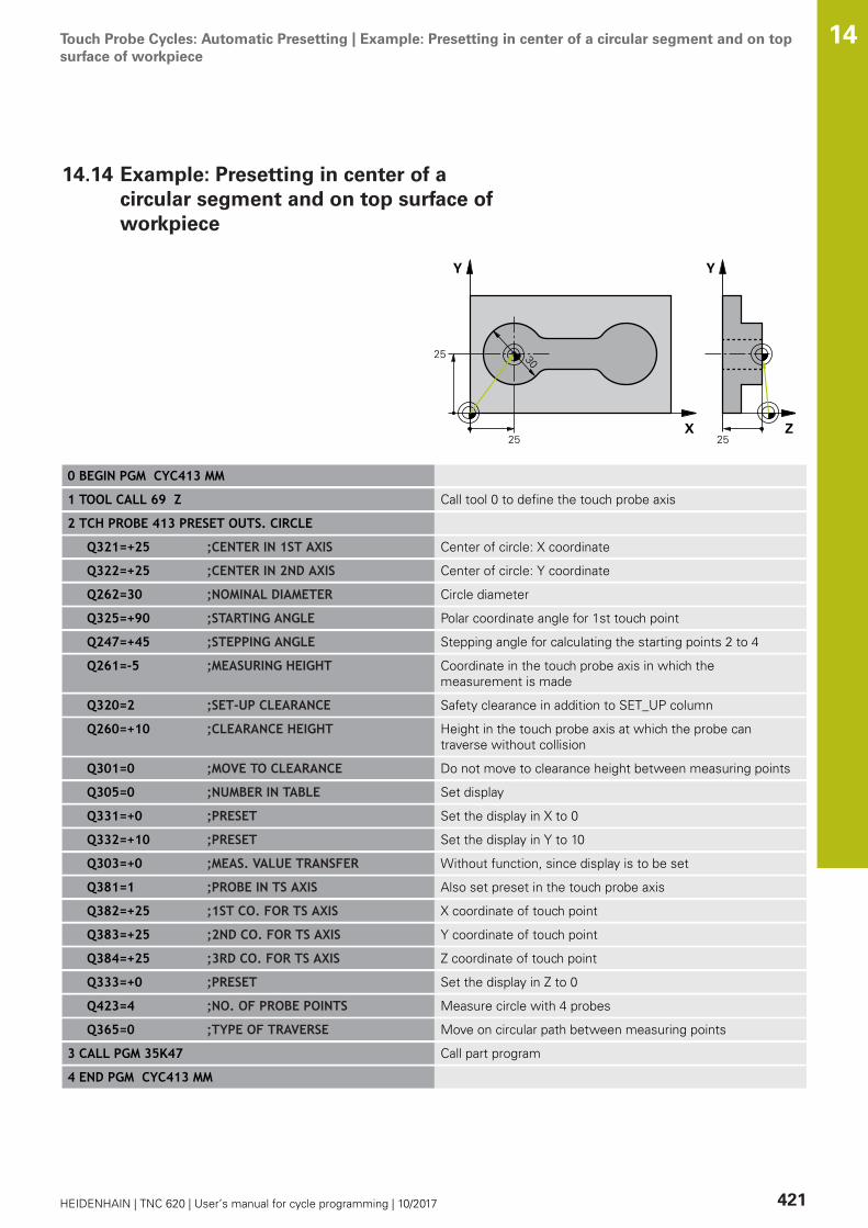
Touch Probe Cycles: Automatic Presetting | Example: Presetting in center of a circular segment and on topsurface of workpiece
14
HEIDENHAIN | TNC 620 | User’s manual for cycle programming | 10/2017 421
14.14 Example: Presetting in center of acircular segment and on top surface ofworkpiece
0 BEGIN PGM CYC413 MM
1 TOOL CALL 69 Z Call tool 0 to define the touch probe axis
2 TCH PROBE 413 PRESET OUTS. CIRCLE
Q321=+25 ;CENTER IN 1ST AXIS Center of circle: X coordinate
Q322=+25 ;CENTER IN 2ND AXIS Center of circle: Y coordinate
Q262=30 ;NOMINAL DIAMETER Circle diameter
Q325=+90 ;STARTING ANGLE Polar coordinate angle for 1st touch point
Q247=+45 ;STEPPING ANGLE Stepping angle for calculating the starting points 2 to 4
Q261=-5 ;MEASURING HEIGHT Coordinate in the touch probe axis in which themeasurement is made
Q320=2 ;SET-UP CLEARANCE Safety clearance in addition to SET_UP column
Q260=+10 ;CLEARANCE HEIGHT Height in the touch probe axis at which the probe cantraverse without collision
Q301=0 ;MOVE TO CLEARANCE Do not move to clearance height between measuring points
Q305=0 ;NUMBER IN TABLE Set display
Q331=+0 ;PRESET Set the display in X to 0
Q332=+10 ;PRESET Set the display in Y to 10
Q303=+0 ;MEAS. VALUE TRANSFER Without function, since display is to be set
Q381=1 ;PROBE IN TS AXIS Also set preset in the touch probe axis
Q382=+25 ;1ST CO. FOR TS AXIS X coordinate of touch point
Q383=+25 ;2ND CO. FOR TS AXIS Y coordinate of touch point
Q384=+25 ;3RD CO. FOR TS AXIS Z coordinate of touch point
Q333=+0 ;PRESET Set the display in Z to 0
Q423=4 ;NO. OF PROBE POINTS Measure circle with 4 probes
Q365=0 ;TYPE OF TRAVERSE Move on circular path between measuring points
3 CALL PGM 35K47 Call part program
4 END PGM CYC413 MM

Touch Probe Cycles: Automatic Presetting | Example: Presetting on top surface of workpiece and in center ofa bolt hole circle
14
422 HEIDENHAIN | TNC 620 | User’s manual for cycle programming | 10/2017
14.15 Example: Presetting on top surface ofworkpiece and in center of a bolt holecircle
The measured bolt hole center shall be written in thepreset table so that it may be used at a later time.
0 BEGIN PGM CYC416 MM
1 TOOL CALL 69 Z Call tool 0 to define the touch probe axis
2 TCH POBE 417 PRESET IN TS AXIS Cycle definition for presetting in the touch probe axis
Q263=+7.5 ;1ST POINT 1ST AXIS Touch point: X coordinate
Q264=+7.5 ;1ST POINT 2ND AXIS Touch point: Y coordinate
Q294=+25 ;1ST POINT 3RD AXIS Touch point: Z coordinate
Q320=0 ;SET-UP CLEARANCE Safety clearance in addition to SET_UP column
Q260=+50 ;CLEARANCE HEIGHT Height in the touch probe axis at which the probe cantraverse without collision
Q305=1 ;NUMBER IN TABLE Write Z coordinate in line 1
Q333=+0 ;PRESET Set touch-probe axis to 0
Q303=+1 ;MEAS. VALUE TRANSFER In the preset table PRESET.PR, save the calculated presetreferenced to the machine-based coordinate system (REFsystem)
3 TCH PROBE 416 PRESET CIRCLE CENTER
Q273=+35 ;CENTER IN 1ST AXIS Center of the bolt hole circle: X coordinate
Q274=+35 ;CENTER IN 2ND AXIS Center of the bolt hole circle: Y coordinate
Q262=50 ;NOMINAL DIAMETER Diameter of the bolt hole circle
Q291=+90 ;ANGLE OF 1ST HOLE Polar coordinate angle for 1st hole center 1
Q292=+180 ;ANGLE OF 2ND HOLE Polar coordinate angle for 2nd hole center 2
Q293=+270 ;ANGLE OF 3RD HOLE Polar coordinate angle for 3rd hole center 3
Q261=+15 ;MEASURING HEIGHT Coordinate in the touch probe axis in which themeasurement is made
Q260=+10 ;CLEARANCE HEIGHT Height in the touch probe axis at which the probe cantraverse without collision
Q305=1 ;NUMBER IN TABLE Enter center of bolt hole circle (X and Y) in line 1
Q331=+0 ;PRESET
Q332=+0 ;PRESET

Touch Probe Cycles: Automatic Presetting | Example: Presetting on top surface of workpiece and in center ofa bolt hole circle
14
HEIDENHAIN | TNC 620 | User’s manual for cycle programming | 10/2017 423
Q303=+1 ;MEAS. VALUE TRANSFER In the preset table PRESET.PR, save the calculated presetreferenced to the machine-based coordinate system (REFsystem)
Q381=0 ;PROBE IN TS AXIS Do not set a preset in the touch probe axis
Q382=+0 ;1ST CO. FOR TS AXIS No function
Q383=+0 ;2ND CO. FOR TS AXIS No function
Q384=+0 ;3RD CO. FOR TS AXIS No function
Q333=+0 ;PRESET No function
Q320=0 ;SET-UP CLEARANCE. Safety clearance in addition to SET_UP column
4 CYCL DEF 247 PRESETTING Activate new preset with Cycle 247
Q339=1 ;PRESET NUMBER
6 CALL PGM 35KLZ Call part program
7 END PGM CYC416 MM

15Touch Probe
Cycles: AutomaticWorkpieceInspection

Touch Probe Cycles: Automatic Workpiece Inspection | Fundamentals 15
426 HEIDENHAIN | TNC 620 | User’s manual for cycle programming | 10/2017
15.1 Fundamentals
Overview
NOTICEDanger of collision!
Cycles for coordinate transformation must not be active duringexecution of the touch probe cycles.
Do not activate the following cycles before using touch probecycles: Cycle 7 DATUM SHIFT,Cycle 8 MIRROR IMAGE, Cycle10 ROTATION,Cycle 11 SCALING and 26 AXIS-SPECIFICSCALINGReset any coordinate transformations beforehand
The control must be specially prepared by the machinetool builder for the use of a 3-D touch probe.HEIDENHAIN only gives warranty for the function of theprobing cycles if HEIDENHAIN touch probes are used.
The TNC offers twelve cycles for measuring workpiecesautomatically.
Soft key Cycle Page
0 REFERENCE PLANEMeasuring a coordinate in a selectableaxis
432
1 POLAR PRESETMeasuring a point in a probing direc-tion
433
420 MEASURE ANGLEMeasuring an angle in the workingplane
434
421 MEASURE HOLEMeasuring the position and diameterof a hole
437
422 MEASURE CIRCLE OUTSIDEMeasuring the position and diameterof a circular stud
441
423 MEASURE RECTANGLE INSIDEMeasuring the position, length andwidth of a rectangular pocket
445
424 MEASURE RECTANGLEOUTSIDEMeasuring the position, length andwidth of a rectangular stud
448
425 MEASURE INSIDE WIDTH(2nd soft-key level) Measuring slotwidth
451

Touch Probe Cycles: Automatic Workpiece Inspection | Fundamentals 15
HEIDENHAIN | TNC 620 | User’s manual for cycle programming | 10/2017 427
Soft key Cycle Page
426 MEASURE RIDGE WIDTH(2nd soft-key row) Measuring thewidth of a ridge
454
427 MEASURE COORDINATE(2nd soft-key row) Measuring anycoordinate in a selectable axis
457
430 MEASURE BOLT HOLE CIRCLE(2nd soft-key row) Measuring positionand diameter of a bolt hole circle
460
431 MEASURE PLANE(2nd soft-key row) Measuring the Aand B axis angles of a plane
463
Recording the results of measurementFor all cycles in which you automatically measure workpieces (withthe exception of Cycles 0 and 1), you can have the TNC recordthe measurement results. In the respective probing cycle you candefine if the TNC is to
Save the measuring log to a fileInterrupt program run and display the measuring log on thescreenCreate no measuring log
If you want to save the measuring log to a file the TNC, by default,saves the data as an ASCII file. The TNC will save the file in thedirectory that also contains the associated NC program.
Use the HEIDENHAIN data transfer software TNCRemoif you wish to output the measuring log over the datainterface.

Touch Probe Cycles: Automatic Workpiece Inspection | Fundamentals 15
428 HEIDENHAIN | TNC 620 | User’s manual for cycle programming | 10/2017
Example: Measuring log for touch probe cycle 421:
Measuring log for Probing Cycle 421 Hole Measuring
Date: 30-06-2005Time: 6:55:04Measuring program: TNC:\GEH35712\CHECK1.H
Nominal values:Center in reference axis: 50.0000Center in minor axis: 65.0000Diameter: 12.0000
Given limit values:Maximum limit for center in referenceaxis:
50.1000
Minimum limit for center in referenceaxis:
49.9000
Maximum limit for center in minor axis: 65.1000
Minimum limit for center in minor axis: 64.9000Maximum dimension for hole: 12.0450Minimum dimension for hole: 12.0000
Actual values:Center in reference axis: 50.0810Center in minor axis: 64.9530Diameter: 12.0259
Deviations:Center in reference axis: 0.0810Center in minor axis: -0.0470Diameter: 0.0259
Further measuring results: Measuringheight:
-5.0000
End of measuring log

Touch Probe Cycles: Automatic Workpiece Inspection | Fundamentals 15
HEIDENHAIN | TNC 620 | User’s manual for cycle programming | 10/2017 429
Measurement results in Q parametersThe TNC saves the measurement results of the respective touchprobe cycle in the globally effective Q parameters Q150 to Q160.Deviations from the nominal value are saved in the parametersQ161 to Q166. Note the table of result parameters listed withevery cycle description.During cycle definition the TNC also shows the result parametersfor the respective cycle in a help graphic (see figure at upper right).The highlighted result parameter belongs to that input parameter.
Classification of resultsFor some cycles you can inquire the status of measuring resultsthrough the globally effective Q parameters Q180 to Q182.
Class of results Parameter value
Measurement results are within tolerance Q180 = 1
Rework is required Q181 = 1
Scrap Q182 = 1
The TNC sets the rework or scrap marker as soon as one of themeasuring values falls outside of tolerance. To determine whichof the measuring results lies outside of tolerance, check themeasuring log, or compare the respective measuring results (Q150to Q160) with their limit values.In Cycle 427 the TNC assumes that you are measuring an outsidedimension (stud). However, you can correct the status of themeasurement by entering the correct maximum and minimumdimension together with the probing direction.
The TNC also sets the status markers if you have notdefined any tolerance values or maximum/minimumdimensions.
Tolerance monitoringFor most of the cycles for workpiece inspection you can have theTNC perform tolerance monitoring. This requires that you definethe necessary limit values during cycle definition. If you do notwish to monitor for tolerances, simply leave the 0 (the defaultvalue) in the monitoring parameters.

Touch Probe Cycles: Automatic Workpiece Inspection | Fundamentals 15
430 HEIDENHAIN | TNC 620 | User’s manual for cycle programming | 10/2017
Tool monitoringFor some cycles for workpiece inspection you can have the TNCperform tool monitoring. The TNC then monitors whether
The tool radius should be compensated because of thedeviations from the nominal value (values in Q16x).The deviations from the nominal value (values in Q16x) aregreater than the tool breakage tolerance.
Tool compensation
This function works only:If the tool table is active.If tool monitoring is switched on in the cycle (entera tool name or Q330 unequal to 0). Select the toolname input by soft key. The TNC no longer displaysthe right single quotation mark.
If you perform several compensation measurements,the TNC adds the respective measured deviation to thevalue stored in the tool table.
Milling tool: If you reference parameter Q330 to a milling tool,the appropriate values are compensated in the following way: theTNC basically always compensates the tool radius in column DR ofthe tool table, even if the measured deviation is within the statedtolerance. You can inquire whether re-working is necessary viaparameter Q181 in the NC program (Q181=1: must be reworked).

Touch Probe Cycles: Automatic Workpiece Inspection | Fundamentals 15
HEIDENHAIN | TNC 620 | User’s manual for cycle programming | 10/2017 431
Tool breakage monitoring
This function works only:If the tool table is active.If tool monitoring is switched on in the cycle (enterQ330 not equal to 0).If the breakage tolerance RBREAK for the toolnumber entered in the table is greater than 0 (seealso the User's Manual, section 5.2 "Tool Data").
The TNC will output an error message and stop program run if themeasured deviation is greater than the breakage tolerance of thetool. At the same time the tool will be deactivated in the tool table(column TL = L).
Reference system for measurement resultsThe TNC transfers all the measurement results to the resultparameters and the log file in the active coordinate system, oras the case may be, the shifted and/or rotated/tilted coordinatesystem.
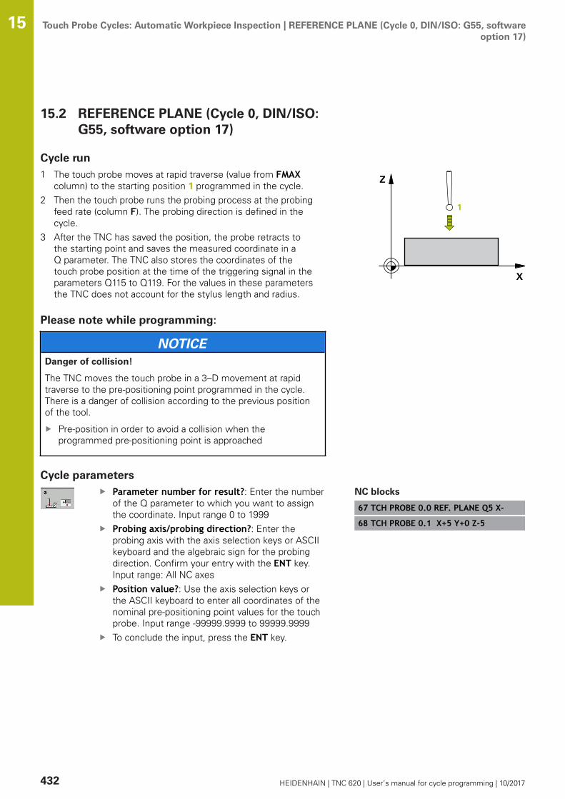
Touch Probe Cycles: Automatic Workpiece Inspection | REFERENCE PLANE (Cycle 0, DIN/ISO: G55, softwareoption 17)
15
432 HEIDENHAIN | TNC 620 | User’s manual for cycle programming | 10/2017
15.2 REFERENCE PLANE (Cycle 0, DIN/ISO:G55, software option 17)
Cycle run1 The touch probe moves at rapid traverse (value from FMAX
column) to the starting position 1 programmed in the cycle.2 Then the touch probe runs the probing process at the probing
feed rate (column F). The probing direction is defined in thecycle.
3 After the TNC has saved the position, the probe retracts tothe starting point and saves the measured coordinate in aQ parameter. The TNC also stores the coordinates of thetouch probe position at the time of the triggering signal in theparameters Q115 to Q119. For the values in these parametersthe TNC does not account for the stylus length and radius.
Please note while programming:
NOTICEDanger of collision!
The TNC moves the touch probe in a 3–D movement at rapidtraverse to the pre-positioning point programmed in the cycle.There is a danger of collision according to the previous positionof the tool.
Pre-position in order to avoid a collision when theprogrammed pre-positioning point is approached
Cycle parametersParameter number for result?: Enter the numberof the Q parameter to which you want to assignthe coordinate. Input range 0 to 1999Probing axis/probing direction?: Enter theprobing axis with the axis selection keys or ASCIIkeyboard and the algebraic sign for the probingdirection. Confirm your entry with the ENT key.Input range: All NC axesPosition value?: Use the axis selection keys orthe ASCII keyboard to enter all coordinates of thenominal pre-positioning point values for the touchprobe. Input range -99999.9999 to 99999.9999To conclude the input, press the ENT key.
NC blocks
67 TCH PROBE 0.0 REF. PLANE Q5 X-
68 TCH PROBE 0.1 X+5 Y+0 Z-5
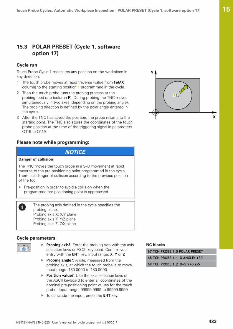
Touch Probe Cycles: Automatic Workpiece Inspection | POLAR PRESET (Cycle 1, software option 17) 15
HEIDENHAIN | TNC 620 | User’s manual for cycle programming | 10/2017 433
15.3 POLAR PRESET (Cycle 1, softwareoption 17)
Cycle runTouch Probe Cycle 1 measures any position on the workpiece inany direction.1 The touch probe moves at rapid traverse (value from FMAX
column) to the starting position 1 programmed in the cycle.2 Then the touch probe runs the probing process at the
probing feed rate (column F). During probing the TNC movessimultaneously in two axes (depending on the probing angle).The probing direction is defined by the polar angle entered inthe cycle.
3 After the TNC has saved the position, the probe returns to thestarting point. The TNC also stores the coordinates of the touchprobe position at the time of the triggering signal in parametersQ115 to Q119.
Please note while programming:
NOTICEDanger of collision!
The TNC moves the touch probe in a 3–D movement at rapidtraverse to the pre-positioning point programmed in the cycle.There is a danger of collision according to the previous positionof the tool.
Pre-position in order to avoid a collision when theprogrammed pre-positioning point is approached
The probing axis defined in the cycle specifies theprobing plane:Probing axis X: X/Y planeProbing axis Y: Y/Z planeProbing axis Z: Z/X plane
Cycle parametersProbing axis?: Enter the probing axis with the axisselection keys or ASCII keyboard. Confirm yourentry with the ENT key. Input range: X, Y or ZProbing angle?: Angle, measured from theprobing axis, at which the touch probe is to move.Input range -180.0000 to 180.0000Position value?: Use the axis selection keys orthe ASCII keyboard to enter all coordinates of thenominal pre-positioning point values for the touchprobe. Input range -99999.9999 to 99999.9999To conclude the input, press the ENT key.
NC blocks
67 TCH PROBE 1.0 POLAR PRESET
68 TCH PROBE 1.1 X ANGLE: +30
69 TCH PROBE 1.2 X+5 Y+0 Z-5

Touch Probe Cycles: Automatic Workpiece Inspection | MEASURE ANGLE (Cycle 420, DIN/ISO: G420,software option 17)
15
434 HEIDENHAIN | TNC 620 | User’s manual for cycle programming | 10/2017
15.4 MEASURE ANGLE (Cycle 420, DIN/ISO:G420, software option 17)
Cycle runTouch Probe Cycle 420 measures the angle that any straightsurface on the workpiece describes with respect to the referenceaxis of the working plane.1 The TNC positions the touch probe at rapid traverse (value from
FMAX column) following the positioning logic (see "Executingtouch probe cycles", Page 339) to the starting point 1. The TNCoffsets the touch probe by the safety clearance in the directionopposite to the defined traverse direction.
2 Then the touch probe moves to the entered measuring heightand runs the first probing process at the probing feed rate(column F).
3 Then the touch probe moves to the next starting position 2 andfrom there probes the second position.
4 The TNC returns the touch probe to the clearance height andsaves the measured angle in the following Q parameter:
Parameter number Meaning
Q150 The measured angle is referenced tothe reference axis of the machiningplane.
Please note while programming:
Before a cycle definition you must have programmed atool call to define the touch probe axis.If touch probe axis = measuring axis, set Q263 equal toQ265 if the angle about the A axis is to be measured;set Q263 not equal to Q265 if the angle is to bemeasured about the B axis.

Touch Probe Cycles: Automatic Workpiece Inspection | MEASURE ANGLE (Cycle 420, DIN/ISO: G420,software option 17)
15
HEIDENHAIN | TNC 620 | User’s manual for cycle programming | 10/2017 435
Cycle parametersQ263 1st measuring point in 1st axis? (absolute):Coordinate of the first touch point in the referenceaxis of the working plane. Input range -99999.9999to 99999.9999Q264 1st measuring point in 2nd axis?(absolute): Coordinate of the first touch point inthe minor axis of the working plane. Input range-99999.9999 to 99999.9999Q265 2nd measuring point in 1st axis?(absolute): Coordinate of the second touch pointin the reference axis of the working plane. Inputrange -99999.9999 to 99999.9999Q266 2nd measuring point in 2nd axis?(absolute): Coordinate of the second touch pointin the minor axis of the working plane. Input range-99999.9999 to 99999.9999Q272 Meas. axis (1/2/3, 1=ref. axis)?: Axis inwhich the measurement is to be made:1: Reference axis = measuring axis2: Minor axis = measuring axis3: Touch probe axis = measuring axisQ267 Trav. direction 1 (+1=+ / -1=-)?: Directionin which the probe is to approach the workpiece:-1: Negative traverse direction+1: Positive traverse directionQ261 Measuring height in probe axis? (absolute):Coordinate of the ball tip center (= touch point) inthe touch probe axis in which the measurementis to be made. Input range -99999.9999 to99999.9999Q320 Set-up clearance? (incremental): Additionaldistance between measuring point and ball tip.Q320 is added to SET_UP (touch probe table), andis only effective when the preset is probed in thetouch probe axis. Input range 0 to 99999.9999Q260 Clearance height? (absolute): coordinate inthe touch probe axis at which no collision betweentool and workpiece (fixtures) can occur. Inputrange -99999.9999 to 99999.9999
NC blocks
5 TCH PROBE 420 MEASURE ANGLE
Q263=+10 ;1ST POINT 1ST AXIS
Q264=+10 ;1ST POINT 2ND AXIS
Q265=+15 ;2ND PNT IN 1ST AXIS
Q266=+95 ;2ND POINT 2ND AXIS
Q272=1 ;MEASURING AXIS
Q267=-1 ;TRAVERSE DIRECTION
Q261=-5 ;MEASURING HEIGHT
Q320=0 ;SET-UP CLEARANCE
Q260=+10 ;CLEARANCE HEIGHT
Q301=1 ;MOVE TO CLEARANCE
Q281=1 ;MEASURING LOG
Touch Probe Cycles: Automatic Workpiece Inspection | MEASURE ANGLE (Cycle 420, DIN/ISO: G420,software option 17)
15
436 HEIDENHAIN | TNC 620 | User’s manual for cycle programming | 10/2017
Q301 Move to clearance height (0/1)?: Definitionof how the touch probe is to move between themeasuring points:0: Move at measuring height between measuringpoints1: Move at clearance height between measuringpointsQ281 Measuring log (0/1/2)?: Define whether theTNC should create a measuring log: 0: Do not create a measuring log1: Create a measuring log: The TNC saves the logfile TCHPR420.TXT as standard in the directoryTNC:\2: Interrupt program run and output measuring logto the TNC screen (Press NC start to continue theprogram)

Touch Probe Cycles: Automatic Workpiece Inspection | MEASURE HOLE (Cycle 421, DIN/ISO: G421, softwareoption 17)
15
HEIDENHAIN | TNC 620 | User’s manual for cycle programming | 10/2017 437
15.5 MEASURE HOLE (Cycle 421, DIN/ISO:G421, software option 17)
Cycle runTouch Probe Cycle 421 measures the center and diameter of a hole(or circular pocket). If you define the corresponding tolerance valuesin the cycle, the TNC makes a nominal-to-actual value comparisonand saves the deviation value in system parameters.1 Following the positioning logic, the TNC positions the touch
probe at rapid traverse (value from FMAX column) (see"Executing touch probe cycles", Page 339) to touch point 1. TheTNC calculates the touch points from the data in the cycle andthe safety clearance from the SET_UP column of the touchprobe table.
2 Then the touch probe moves to the entered measuring heightand runs the first probing process at the probing feed rate(column F). The TNC derives the probing direction automaticallyfrom the programmed starting angle.
3 Then the touch probe moves in a circular arc either at measuringheight or at clearance height to the next starting point 2 andprobes the second touch point.
4 The TNC positions the probe to starting point 3 and then tostarting point 4 to probe the third and fourth touch points.
5 Finally the TNC returns the touch probe to the clearance heightand saves the actual values and the deviations in the followingQ parameters:
Parameter number Meaning
Q151 Actual value of center in reference axis
Q152 Actual value of center in minor axis
Q153 Actual value of diameter
Q161 Deviation at center of reference axis
Q162 Deviation at center of minor axis
Q163 Deviation from diameter
Please note while programming:
Before a cycle definition you must have programmed atool call to define the touch probe axis.The smaller the angle, the less accurately the TNC cancalculate the hole dimensions. Minimum input value: 5°Parameters Q498 and Q531 have no effect in this cycle.You do not need to make any entries. These parametershave only been integrated for reasons of compatibility.If, for example, you import a program of the contouringcontrol for turning and milling, TNC 640, you will notreceive an error message.

Touch Probe Cycles: Automatic Workpiece Inspection | MEASURE HOLE (Cycle 421, DIN/ISO: G421, softwareoption 17)
15
438 HEIDENHAIN | TNC 620 | User’s manual for cycle programming | 10/2017
Cycle parametersQ273 Center in 1st axis (nom. value)? (absolute):Center of the hole in the reference axis of theworking plane. Input range -99999.9999 to99999.9999Q274 Center in 2nd axis (nom. value)?(absolute): Center of the hole in the minor axisof the working plane. Input range -99999.9999 to99999.9999Q262 Nominal diameter?: Enter the diameter ofthe hole. Input range 0 to 99999.9999Q325 Starting angle? (absolute): Angle betweenthe reference axis of the working plane and thefirst touch point. Input range -360.000 to 360.000Q247 Intermediate stepping angle?(incremental): Angle between two measuringpoints. The algebraic sign of the steppingangle determines the direction of rotation(negative = clockwise) in which the touch probemoves to the next measuring point. If you wish toprobe a circular arc instead of a complete circle,then program the stepping angle to be less than90°. Input range -120.000 to 120.000Q261 Measuring height in probe axis? (absolute):Coordinate of the ball tip center (= touch point) inthe touch probe axis in which the measurementis to be made. Input range -99999.9999 to99999.9999Q320 Set-up clearance? (incremental): Definean additional distance between measuring pointand ball tip. Q320 is added to SET_UP in the touchprobe table. Input range 0 to 99999.9999Q260 Clearance height? (absolute): coordinate inthe touch probe axis at which no collision betweentool and workpiece (fixtures) can occur. Inputrange -99999.9999 to 99999.9999
NC blocks
5 TCH PROBE 421 MEASURE HOLE
Q273=+50 ;CENTER IN 1ST AXIS
Q274=+50 ;CENTER IN 2ND AXIS
Q262=75 ;NOMINAL DIAMETER
Q325=+0 ;STARTING ANGLE
Q247=+60 ;STEPPING ANGLE
Q261=-5 ;MEASURING HEIGHT
Q320=0 ;SET-UP CLEARANCE
Q260=+20 ;CLEARANCE HEIGHT

Touch Probe Cycles: Automatic Workpiece Inspection | MEASURE HOLE (Cycle 421, DIN/ISO: G421, softwareoption 17)
15
HEIDENHAIN | TNC 620 | User’s manual for cycle programming | 10/2017 439
Q301 Move to clearance height (0/1)?: Definitionof how the touch probe is to move between themeasuring points:0: Move at measuring height between measuringpoints1: Move at clearance height between measuringpointsQ275 Maximum limit of size for hole?: Maximumpermissible diameter for the hole (circular pocket).Input range 0 to 99999.9999Q276 Minimum limit of size?: Minimumpermissible diameter for the hole (circular pocket).Input range 0 to 99999.9999Q279 Tolerance for center 1st axis?: Permissibleposition deviation in the reference axis of theworking plane. Input range 0 to 99999.9999Q280 Tolerance for center 2nd axis?: Permissibleposition deviation in the minor axis of the workingplane. Input range 0 to 99999.9999Q281 Measuring log (0/1/2)?: Definition ofwhether TNC should create a measuring log:0: Create no measuring log1: Create measuring log: The TNC will save thelog file TCHPR421.TXT by default in the directorythat also contains the associated NC program.2: Interrupt the program run and display themeasuring log on the TNC screen. Resumeprogram run with NC Start.Q309 PGM stop if tolerance exceeded?:Definition of whether in the event of a violation oftolerance limits the TNC is to interrupt programrun and output an error message:0: Do not interrupt program run, do not output anerror message1: Interrupt program run and output an errormessage
Q301=1 ;MOVE TO CLEARANCE
Q275=75.12;MAXIMUM LIMIT
Q276=74.95;MINIMUM LIMIT
Q279=0.1 ;TOLERANCE 1ST CENTER
Q280=0.1 ;TOLERANCE 2ND CENTER
Q281=1 ;MEASURING LOG
Q309=0 ;PGM STOP TOLERANCE
Q330=0 ;TOOL
Q423=4 ;NO. OF PROBE POINTS
Q365=1 ;TYPE OF TRAVERSE

Touch Probe Cycles: Automatic Workpiece Inspection | MEASURE HOLE (Cycle 421, DIN/ISO: G421, softwareoption 17)
15
440 HEIDENHAIN | TNC 620 | User’s manual for cycle programming | 10/2017
Q330 Tool for monitoring?: Definition ofwhether the TNC is to monitor the tool (see "Toolmonitoring", Page 430). Input range 0 to 32767.9,alternatively tool name with maximum of 16characters0: Monitoring inactive>0: Number or name of the tool that the TNC usedfor machining. You are able to apply a tool via softkey directly from the tool table.Q423 No. probe points in plane (4/3)?: Definewhether the TNC should measure the stud with 4or 3 probing points:4: Use 4 measuring points (standard setting)3: Use 3 measuring pointsQ365 Type of traverse? Line=0/arc=1: Definitionof the path function with which the tool is to movebetween the measuring points if "traverse toclearance height" (Q301=1) is active:0: Move in a straight line between machiningoperations1: Move in a circular arc on the pitch circlediameter between machining operationsParameters Q498 and Q531 have no effect in thiscycle. You do not need to make any entries. Theseparameters have only been integrated for reasonsof compatibility. If, for example, you import aprogram of the contouring control for turning andmilling, TNC 640, you will not receive an errormessage.
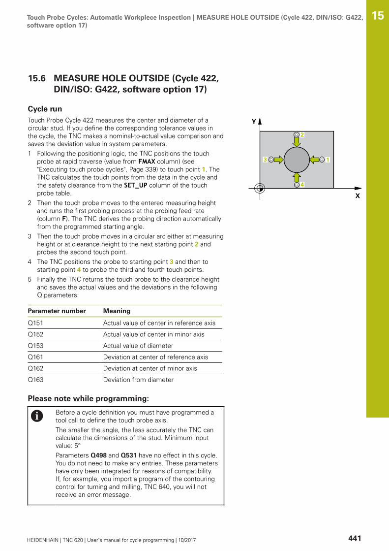
Touch Probe Cycles: Automatic Workpiece Inspection | MEASURE HOLE OUTSIDE (Cycle 422, DIN/ISO: G422,software option 17)
15
HEIDENHAIN | TNC 620 | User’s manual for cycle programming | 10/2017 441
15.6 MEASURE HOLE OUTSIDE (Cycle 422,DIN/ISO: G422, software option 17)
Cycle runTouch Probe Cycle 422 measures the center and diameter of acircular stud. If you define the corresponding tolerance values inthe cycle, the TNC makes a nominal-to-actual value comparison andsaves the deviation value in system parameters.1 Following the positioning logic, the TNC positions the touch
probe at rapid traverse (value from FMAX column) (see"Executing touch probe cycles", Page 339) to touch point 1. TheTNC calculates the touch points from the data in the cycle andthe safety clearance from the SET_UP column of the touchprobe table.
2 Then the touch probe moves to the entered measuring heightand runs the first probing process at the probing feed rate(column F). The TNC derives the probing direction automaticallyfrom the programmed starting angle.
3 Then the touch probe moves in a circular arc either at measuringheight or at clearance height to the next starting point 2 andprobes the second touch point.
4 The TNC positions the probe to starting point 3 and then tostarting point 4 to probe the third and fourth touch points.
5 Finally the TNC returns the touch probe to the clearance heightand saves the actual values and the deviations in the followingQ parameters:
Parameter number Meaning
Q151 Actual value of center in reference axis
Q152 Actual value of center in minor axis
Q153 Actual value of diameter
Q161 Deviation at center of reference axis
Q162 Deviation at center of minor axis
Q163 Deviation from diameter
Please note while programming:
Before a cycle definition you must have programmed atool call to define the touch probe axis.The smaller the angle, the less accurately the TNC cancalculate the dimensions of the stud. Minimum inputvalue: 5°Parameters Q498 and Q531 have no effect in this cycle.You do not need to make any entries. These parametershave only been integrated for reasons of compatibility.If, for example, you import a program of the contouringcontrol for turning and milling, TNC 640, you will notreceive an error message.

Touch Probe Cycles: Automatic Workpiece Inspection | MEASURE HOLE OUTSIDE (Cycle 422, DIN/ISO: G422,software option 17)
15
442 HEIDENHAIN | TNC 620 | User’s manual for cycle programming | 10/2017
Cycle parametersQ273 Center in 1st axis (nom. value)? (absolute):Center of the stud in the reference axis of theworking plane. Input range -99999.9999 to99999.9999Q274 Center in 2nd axis (nom. value)?(absolute): Center of the stud in the minor axisof the working plane. Input range -99999.9999 to99999.9999Q262 Nominal diameter?: Enter the diameter ofthe stud. Input range 0 to 99999.9999Q325 Starting angle? (absolute): Angle betweenthe reference axis of the working plane and thefirst touch point. Input range -360.000 to 360.000Q247 Intermediate stepping angle?(incremental): Angle between two measuringpoints. The algebraic sign of the stepping angledetermines the direction of rotation (negative= clockwise). If you wish to probe a circular arcinstead of a complete circle, then program thestepping angle to be less than 90°. Input range-120.0000 to 120.0000Q261 Measuring height in probe axis? (absolute):Coordinate of the ball tip center (= touch point) inthe touch probe axis in which the measurementis to be made. Input range -99999.9999 to99999.9999Q320 Set-up clearance? (incremental): Definean additional distance between measuring pointand ball tip. Q320 is added to SET_UP in the touchprobe table. Input range 0 to 99999.9999Q260 Clearance height? (absolute): coordinate inthe touch probe axis at which no collision betweentool and workpiece (fixtures) can occur. Inputrange -99999.9999 to 99999.9999Q301 Move to clearance height (0/1)?: Definitionof how the touch probe is to move between themeasuring points:0: Move at measuring height between measuringpoints1: Move at clearance height between measuringpoints
NC blocks
5 TCH PROBE 422 MEAS. CIRCLEOUTSIDE
Q273=+50 ;CENTER IN 1ST AXIS
Q274=+50 ;CENTER IN 2ND AXIS
Q262=75 ;NOMINAL DIAMETER
Q325=+90 ;STARTING ANGLE
Q247=+30 ;STEPPING ANGLE
Q261=-5 ;MEASURING HEIGHT
Q320=0 ;SET-UP CLEARANCE
Q260=+10 ;CLEARANCE HEIGHT
Q301=0 ;MOVE TO CLEARANCE
Q277=35.15;MAXIMUM LIMIT
Q278=34.9 ;MINIMUM LIMIT
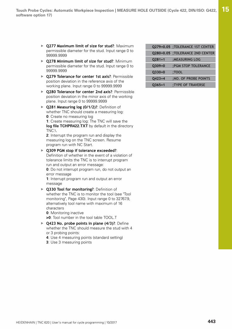
Touch Probe Cycles: Automatic Workpiece Inspection | MEASURE HOLE OUTSIDE (Cycle 422, DIN/ISO: G422,software option 17)
15
HEIDENHAIN | TNC 620 | User’s manual for cycle programming | 10/2017 443
Q277 Maximum limit of size for stud?: Maximumpermissible diameter for the stud. Input range 0 to99999.9999Q278 Minimum limit of size for stud?: Minimumpermissible diameter for the stud. Input range 0 to99999.9999Q279 Tolerance for center 1st axis?: Permissibleposition deviation in the reference axis of theworking plane. Input range 0 to 99999.9999Q280 Tolerance for center 2nd axis?: Permissibleposition deviation in the minor axis of the workingplane. Input range 0 to 99999.9999Q281 Measuring log (0/1/2)?: Definition ofwhether TNC should create a measuring log:0: Create no measuring log1: Create measuring log: The TNC will save thelog file TCHPR422.TXT by default in the directoryTNC:\.2: Interrupt the program run and display themeasuring log on the TNC screen. Resumeprogram run with NC Start.Q309 PGM stop if tolerance exceeded?:Definition of whether in the event of a violation oftolerance limits the TNC is to interrupt programrun and output an error message:0: Do not interrupt program run, do not output anerror message1: Interrupt program run and output an errormessageQ330 Tool for monitoring?: Definition ofwhether the TNC is to monitor the tool (see "Toolmonitoring", Page 430). Input range 0 to 32767.9,alternatively tool name with maximum of 16characters0: Monitoring inactive>0: Tool number in the tool table TOOL.TQ423 No. probe points in plane (4/3)?: Definewhether the TNC should measure the stud with 4or 3 probing points:4: Use 4 measuring points (standard setting)3: Use 3 measuring points
Q279=0.05 ;TOLERANCE 1ST CENTER
Q280=0.05 ;TOLERANCE 2ND CENTER
Q281=1 ;MEASURING LOG
Q309=0 ;PGM STOP TOLERANCE
Q330=0 ;TOOL
Q423=4 ;NO. OF PROBE POINTS
Q365=1 ;TYPE OF TRAVERSE

Touch Probe Cycles: Automatic Workpiece Inspection | MEASURE HOLE OUTSIDE (Cycle 422, DIN/ISO: G422,software option 17)
15
444 HEIDENHAIN | TNC 620 | User’s manual for cycle programming | 10/2017
Q365 Type of traverse? Line=0/arc=1: Definitionof the path function with which the tool is to movebetween the measuring points if "traverse toclearance height" (Q301=1) is active:0: Move in a straight line between machiningoperations1: Move in a circular arc on the pitch circlediameter between machining operationsParameters Q498 and Q531 have no effect in thiscycle. You do not need to make any entries. Theseparameters have only been integrated for reasonsof compatibility. If, for example, you import aprogram of the contouring control for turning andmilling, TNC 640, you will not receive an errormessage.
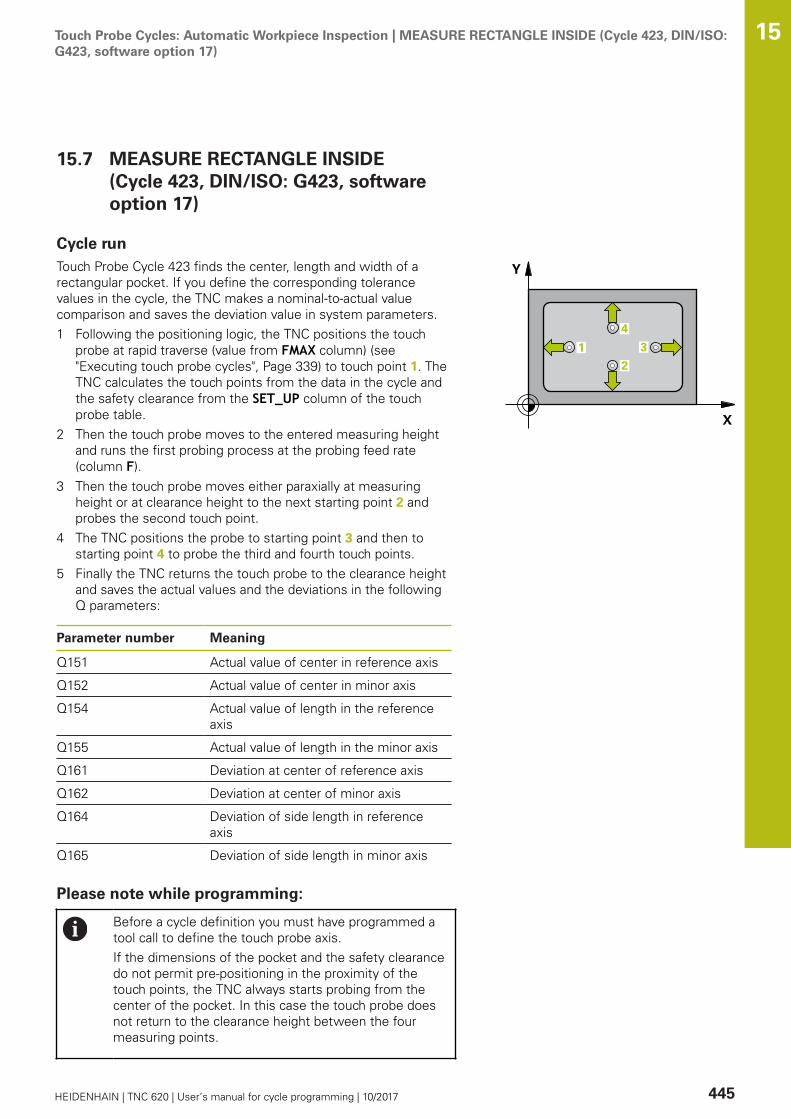
Touch Probe Cycles: Automatic Workpiece Inspection | MEASURE RECTANGLE INSIDE (Cycle 423, DIN/ISO:G423, software option 17)
15
HEIDENHAIN | TNC 620 | User’s manual for cycle programming | 10/2017 445
15.7 MEASURE RECTANGLE INSIDE(Cycle 423, DIN/ISO: G423, softwareoption 17)
Cycle runTouch Probe Cycle 423 finds the center, length and width of arectangular pocket. If you define the corresponding tolerancevalues in the cycle, the TNC makes a nominal-to-actual valuecomparison and saves the deviation value in system parameters.1 Following the positioning logic, the TNC positions the touch
probe at rapid traverse (value from FMAX column) (see"Executing touch probe cycles", Page 339) to touch point 1. TheTNC calculates the touch points from the data in the cycle andthe safety clearance from the SET_UP column of the touchprobe table.
2 Then the touch probe moves to the entered measuring heightand runs the first probing process at the probing feed rate(column F).
3 Then the touch probe moves either paraxially at measuringheight or at clearance height to the next starting point 2 andprobes the second touch point.
4 The TNC positions the probe to starting point 3 and then tostarting point 4 to probe the third and fourth touch points.
5 Finally the TNC returns the touch probe to the clearance heightand saves the actual values and the deviations in the followingQ parameters:
Parameter number Meaning
Q151 Actual value of center in reference axis
Q152 Actual value of center in minor axis
Q154 Actual value of length in the referenceaxis
Q155 Actual value of length in the minor axis
Q161 Deviation at center of reference axis
Q162 Deviation at center of minor axis
Q164 Deviation of side length in referenceaxis
Q165 Deviation of side length in minor axis
Please note while programming:
Before a cycle definition you must have programmed atool call to define the touch probe axis.If the dimensions of the pocket and the safety clearancedo not permit pre-positioning in the proximity of thetouch points, the TNC always starts probing from thecenter of the pocket. In this case the touch probe doesnot return to the clearance height between the fourmeasuring points.

Touch Probe Cycles: Automatic Workpiece Inspection | MEASURE RECTANGLE INSIDE (Cycle 423, DIN/ISO:G423, software option 17)
15
446 HEIDENHAIN | TNC 620 | User’s manual for cycle programming | 10/2017
Cycle parametersQ273 Center in 1st axis (nom. value)? (absolute):Center of the pocket in the reference axis ofthe working plane. Input range -99999.9999 to99999.9999Q274 Center in 2nd axis (nom. value)?(absolute): Center of the pocket in the minor axisof the working plane. Input range -99999.9999 to99999.9999Q282 1st side length (nominal value)?: Pocketlength, parallel to the reference axis of the workingplane. Input range 0 to 99999.9999Q283 2nd side length (nominal value)?: Pocketlength, parallel to the minor axis of the workingplane. Input range 0 to 99999.9999Q261 Measuring height in probe axis? (absolute):Coordinate of the ball tip center (= touch point) inthe touch probe axis in which the measurementis to be made. Input range -99999.9999 to99999.9999Q320 Set-up clearance? (incremental): Definean additional distance between measuring pointand ball tip. Q320 is added to SET_UP in the touchprobe table. Input range 0 to 99999.9999Q260 Clearance height? (absolute): coordinate inthe touch probe axis at which no collision betweentool and workpiece (fixtures) can occur. Inputrange -99999.9999 to 99999.9999Q301 Move to clearance height (0/1)?: Definitionof how the touch probe is to move between themeasuring points:0: Move at measuring height between measuringpoints1: Move at clearance height between measuringpointsQ284 Max. size limit 1st side length?: Maximumpermissible length of the pocket. Input range 0 to99999.9999Q285 Min. size limit 1st side length?: Minimumpermissible length of the pocket. Input range 0 to99999.9999Q286 Max. size limit 2nd side length?: Maximumpermissible width of the pocket. Input range 0 to99999.9999Q287 Min. size limit 2nd side length?: Minimumpermissible width of the pocket. Input range 0 to99999.9999
NC blocks
5 TCH PROBE 423 MEAS. RECTAN.INSIDE
Q273=+50 ;CENTER IN 1ST AXIS
Q274=+50 ;CENTER IN 2ND AXIS
Q282=80 ;FIRST SIDE LENGTH
Q283=60 ;2ND SIDE LENGTH
Q261=-5 ;MEASURING HEIGHT
Q320=0 ;SET-UP CLEARANCE
Q260=+10 ;CLEARANCE HEIGHT
Q301=1 ;MOVE TO CLEARANCE
Q284=0 ;MAX. LIMIT 1ST SIDE
Q285=0 ;MIN. LIMIT 1ST SIDE
Q286=0 ;MAX. LIMIT 2ND SIDE
Q287=0 ;MIN. LIMIT 2ND SIDE
Q279=0 ;TOLERANCE 1ST CENTER
Q280=0 ;TOLERANCE 2ND CENTER
Q281=1 ;MEASURING LOG
Q309=0 ;PGM STOP TOLERANCE
Q330=0 ;TOOL

Touch Probe Cycles: Automatic Workpiece Inspection | MEASURE RECTANGLE INSIDE (Cycle 423, DIN/ISO:G423, software option 17)
15
HEIDENHAIN | TNC 620 | User’s manual for cycle programming | 10/2017 447
Q279 Tolerance for center 1st axis?: Permissibleposition deviation in the reference axis of theworking plane. Input range 0 to 99999.9999Q280 Tolerance for center 2nd axis?: Permissibleposition deviation in the minor axis of the workingplane. Input range 0 to 99999.9999Q281 Measuring log (0/1/2)?: Definition ofwhether TNC should create a measuring log:0: Create no measuring log1: Create measuring log: The TNC will save thelog file TCHPR423.TXT by default in the directoryTNC:\.2: Interrupt the program run and display themeasuring log on the TNC screen. Resumeprogram run with NC Start.Q309 PGM stop if tolerance exceeded?:Definition of whether in the event of a violation oftolerance limits the TNC is to interrupt programrun and output an error message:0: Do not interrupt program run, do not output anerror message1: Interrupt program run and output an errormessageQ330 Tool for monitoring?: Definition ofwhether the TNC is to monitor the tool (see "Toolmonitoring", Page 430). Input range 0 to 32767.9,alternatively tool name with maximum of 16characters0: Monitoring inactive>0: Tool number in the tool table TOOL.T

Touch Probe Cycles: Automatic Workpiece Inspection | MEASURE RECTANGLE OUTSIDE (Cycle 424, DIN/ISO: G424, software option 17)
15
448 HEIDENHAIN | TNC 620 | User’s manual for cycle programming | 10/2017
15.8 MEASURE RECTANGLE OUTSIDE(Cycle 424, DIN/ISO: G424, softwareoption 17)
Cycle runTouch Probe Cycle 424 finds the center, length and width of arectangular stud. If you define the corresponding tolerance valuesin the cycle, the TNC makes a nominal-to-actual value comparisonand saves the deviation values in system parameters.1 The TNC positions the touch probe at rapid traverse (value from
FMAX column) following the positioning logic (see "Executingtouch probe cycles", Page 339) to the starting point 1. The TNCcalculates the touch points from the data in the cycle and thesafety clearance from the SET_UP column of the touch probetable.
2 Then the touch probe moves to the entered measuring heightand runs the first probing process at the probing feed rate(column F).
3 Then the touch probe moves either paraxially at measuringheight or at clearance height to the next starting point 2 andprobes the second touch point.
4 The TNC positions the probe to starting point 3 and then tostarting point 4 to probe the third and fourth touch points.
5 Finally the TNC returns the touch probe to the clearance heightand saves the actual values and the deviations in the followingQ parameters:
Parameter number Meaning
Q151 Actual value of center in reference axis
Q152 Actual value of center in minor axis
Q154 Actual value of length in the referenceaxis
Q155 Actual value of length in the minor axis
Q161 Deviation at center of reference axis
Q162 Deviation at center of minor axis
Q164 Deviation of side length in referenceaxis
Q165 Deviation of side length in minor axis
Please note while programming:
Before a cycle definition you must have programmed atool call to define the touch probe axis.

Touch Probe Cycles: Automatic Workpiece Inspection | MEASURE RECTANGLE OUTSIDE (Cycle 424, DIN/ISO: G424, software option 17)
15
HEIDENHAIN | TNC 620 | User’s manual for cycle programming | 10/2017 449
Cycle parametersQ273 Center in 1st axis (nom. value)? (absolute):Center of the stud in the reference axis of theworking plane. Input range -99999.9999 to99999.9999Q274 Center in 2nd axis (nom. value)?(absolute): Center of the stud in the minor axisof the working plane. Input range -99999.9999 to99999.9999Q282 1st side length (nominal value)?: Studlength, parallel to the reference axis of the workingplane. Input range 0 to 99999.9999Q283 2nd side length (nominal value)?: Studlength, parallel to the minor axis of the workingplane. Input range 0 to 99999.9999Q261 Measuring height in probe axis? (absolute):Coordinate of the ball tip center (= touch point) inthe touch probe axis in which the measurementis to be made. Input range -99999.9999 to99999.9999Q320 Set-up clearance? (incremental): Definean additional distance between measuring pointand ball tip. Q320 is added to SET_UP in the touchprobe table. Input range 0 to 99999.9999Q260 Clearance height? (absolute): coordinate inthe touch probe axis at which no collision betweentool and workpiece (fixtures) can occur. Inputrange -99999.9999 to 99999.9999Q301 Move to clearance height (0/1)?: Definitionof how the touch probe is to move between themeasuring points:0: Move at measuring height between measuringpoints1: Move at clearance height between measuringpointsQ284 Max. size limit 1st side length?: Maximumpermissible length of the stud. Input range 0 to99999.9999Q285 Min. size limit 1st side length?: Minimumpermissible length of the stud. Input range 0 to99999.9999
NC blocks
5 TCH PROBE 424 MEAS. RECTAN.OUTS.
Q273=+50 ;CENTER IN 1ST AXIS
Q274=+50 ;2ND CENTER 2ND AXIS
Q282=75 ;FIRST SIDE LENGTH
Q283=35 ;2ND SIDE LENGTH
Q261=-5 ;MEASURING HEIGHT
Q320=0 ;SET-UP CLEARANCE
Q260=+20 ;CLEARANCE HEIGHT
Q301=0 ;MOVE TO CLEARANCE
Q284=75.1 ;MAX. LIMIT 1ST SIDE
Q285=74.9 ;MIN. LIMIT 1ST SIDE

Touch Probe Cycles: Automatic Workpiece Inspection | MEASURE RECTANGLE OUTSIDE (Cycle 424, DIN/ISO: G424, software option 17)
15
450 HEIDENHAIN | TNC 620 | User’s manual for cycle programming | 10/2017
Q286 Max. size limit 2nd side length?: Maximumpermissible width of the stud. Input range 0 to99999.9999Q287 Min. size limit 2nd side length?: Minimumpermissible width of the stud. Input range 0 to99999.9999Q279 Tolerance for center 1st axis?: Permissibleposition deviation in the reference axis of theworking plane. Input range 0 to 99999.9999Q280 Tolerance for center 2nd axis?: Permissibleposition deviation in the minor axis of the workingplane. Input range 0 to 99999.9999Q281 Measuring log (0/1/2)?: Definition ofwhether TNC should create a measuring log:0: Create no measuring log1: Create measuring log: The TNC will save thelog file TCHPR424.TXT by default in the directoryTNC:\.2: Interrupt the program run and display themeasuring log on the TNC screen. Resumeprogram run with NC Start.Q309 PGM stop if tolerance exceeded?:Definition of whether in the event of a violation oftolerance limits the TNC is to interrupt programrun and output an error message:0: Do not interrupt program run, do not output anerror message1: Interrupt program run and output an errormessageQ330 Tool for monitoring?: Definition ofwhether the TNC is to monitor the tool (see "Toolmonitoring", Page 430). Input range 0 to 32767.9,alternatively tool name with maximum of 16characters0: Monitoring inactive>0: Number or name of the tool that the TNC usedfor machining. You are able to apply a tool via softkey directly from the tool table.
Q286=35 ;MAX. LIMIT 2ND SIDE
Q287=34.95;MIN. LIMIT 2ND SIDE
Q279=0.1 ;TOLERANCE 1ST CENTER
Q280=0.1 ;TOLERANCE 2ND CENTER
Q281=1 ;MEASURING LOG
Q309=0 ;PGM STOP TOLERANCE
Q330=0 ;TOOL
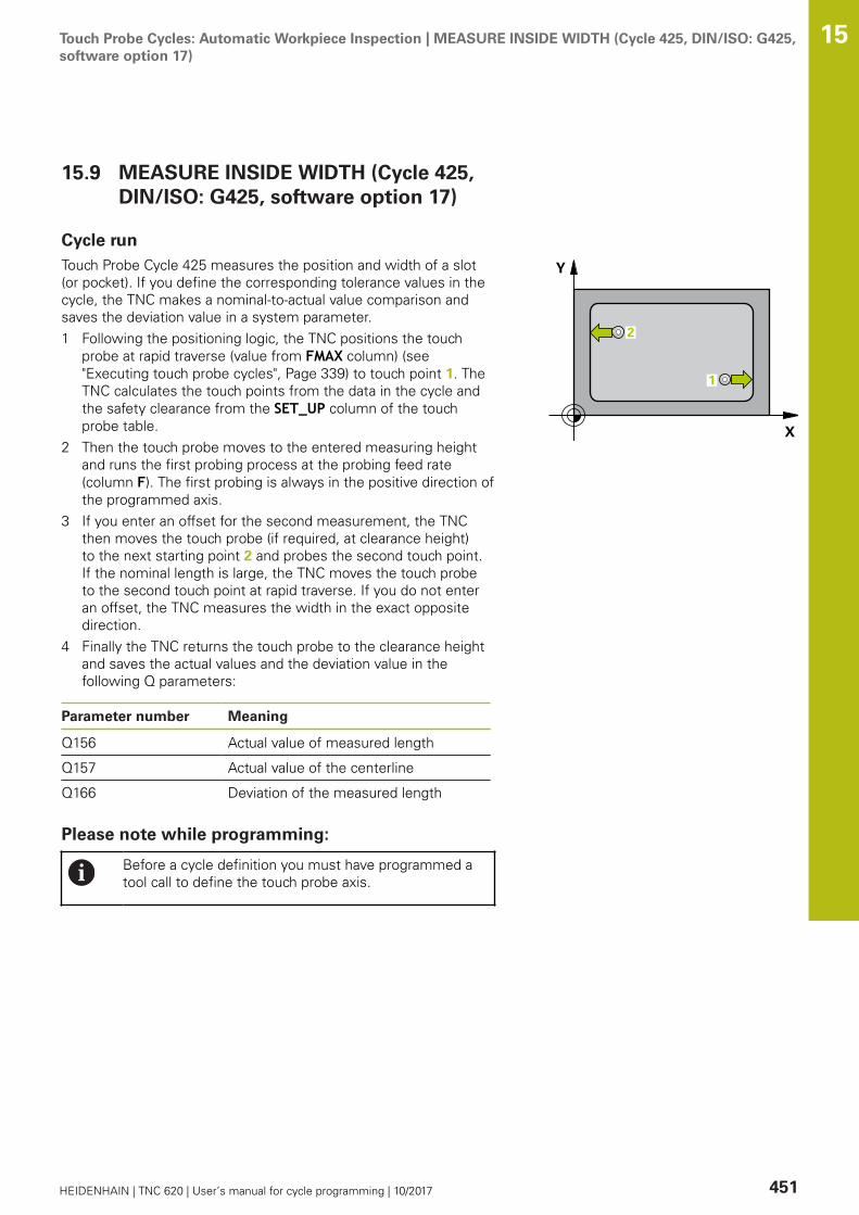
Touch Probe Cycles: Automatic Workpiece Inspection | MEASURE INSIDE WIDTH (Cycle 425, DIN/ISO: G425,software option 17)
15
HEIDENHAIN | TNC 620 | User’s manual for cycle programming | 10/2017 451
15.9 MEASURE INSIDE WIDTH (Cycle 425,DIN/ISO: G425, software option 17)
Cycle runTouch Probe Cycle 425 measures the position and width of a slot(or pocket). If you define the corresponding tolerance values in thecycle, the TNC makes a nominal-to-actual value comparison andsaves the deviation value in a system parameter.1 Following the positioning logic, the TNC positions the touch
probe at rapid traverse (value from FMAX column) (see"Executing touch probe cycles", Page 339) to touch point 1. TheTNC calculates the touch points from the data in the cycle andthe safety clearance from the SET_UP column of the touchprobe table.
2 Then the touch probe moves to the entered measuring heightand runs the first probing process at the probing feed rate(column F). The first probing is always in the positive direction ofthe programmed axis.
3 If you enter an offset for the second measurement, the TNCthen moves the touch probe (if required, at clearance height)to the next starting point 2 and probes the second touch point.If the nominal length is large, the TNC moves the touch probeto the second touch point at rapid traverse. If you do not enteran offset, the TNC measures the width in the exact oppositedirection.
4 Finally the TNC returns the touch probe to the clearance heightand saves the actual values and the deviation value in thefollowing Q parameters:
Parameter number Meaning
Q156 Actual value of measured length
Q157 Actual value of the centerline
Q166 Deviation of the measured length
Please note while programming:
Before a cycle definition you must have programmed atool call to define the touch probe axis.
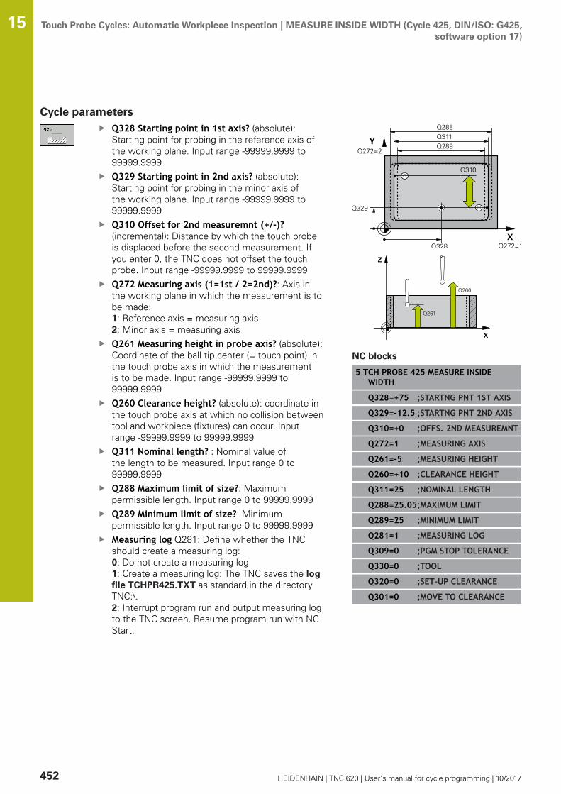
Touch Probe Cycles: Automatic Workpiece Inspection | MEASURE INSIDE WIDTH (Cycle 425, DIN/ISO: G425,software option 17)
15
452 HEIDENHAIN | TNC 620 | User’s manual for cycle programming | 10/2017
Cycle parametersQ328 Starting point in 1st axis? (absolute):Starting point for probing in the reference axis ofthe working plane. Input range -99999.9999 to99999.9999Q329 Starting point in 2nd axis? (absolute):Starting point for probing in the minor axis ofthe working plane. Input range -99999.9999 to99999.9999Q310 Offset for 2nd measuremnt (+/-)?(incremental): Distance by which the touch probeis displaced before the second measurement. Ifyou enter 0, the TNC does not offset the touchprobe. Input range -99999.9999 to 99999.9999Q272 Measuring axis (1=1st / 2=2nd)?: Axis inthe working plane in which the measurement is tobe made:1: Reference axis = measuring axis2: Minor axis = measuring axisQ261 Measuring height in probe axis? (absolute):Coordinate of the ball tip center (= touch point) inthe touch probe axis in which the measurementis to be made. Input range -99999.9999 to99999.9999Q260 Clearance height? (absolute): coordinate inthe touch probe axis at which no collision betweentool and workpiece (fixtures) can occur. Inputrange -99999.9999 to 99999.9999Q311 Nominal length? : Nominal value ofthe length to be measured. Input range 0 to99999.9999Q288 Maximum limit of size?: Maximumpermissible length. Input range 0 to 99999.9999Q289 Minimum limit of size?: Minimumpermissible length. Input range 0 to 99999.9999Measuring log Q281: Define whether the TNCshould create a measuring log: 0: Do not create a measuring log1: Create a measuring log: The TNC saves the logfile TCHPR425.TXT as standard in the directoryTNC:\.2: Interrupt program run and output measuring logto the TNC screen. Resume program run with NCStart.
NC blocks
5 TCH PROBE 425 MEASURE INSIDEWIDTH
Q328=+75 ;STARTNG PNT 1ST AXIS
Q329=-12.5 ;STARTNG PNT 2ND AXIS
Q310=+0 ;OFFS. 2ND MEASUREMNT
Q272=1 ;MEASURING AXIS
Q261=-5 ;MEASURING HEIGHT
Q260=+10 ;CLEARANCE HEIGHT
Q311=25 ;NOMINAL LENGTH
Q288=25.05;MAXIMUM LIMIT
Q289=25 ;MINIMUM LIMIT
Q281=1 ;MEASURING LOG
Q309=0 ;PGM STOP TOLERANCE
Q330=0 ;TOOL
Q320=0 ;SET-UP CLEARANCE
Q301=0 ;MOVE TO CLEARANCE

Touch Probe Cycles: Automatic Workpiece Inspection | MEASURE INSIDE WIDTH (Cycle 425, DIN/ISO: G425,software option 17)
15
HEIDENHAIN | TNC 620 | User’s manual for cycle programming | 10/2017 453
Q309 PGM stop if tolerance exceeded?:Definition of whether in the event of a violation oftolerance limits the TNC is to interrupt programrun and output an error message:0: Do not interrupt program run, do not output anerror message1: Interrupt program run and output an errormessageQ330 Tool for monitoring?: Definition ofwhether the TNC is to monitor the tool (see "Toolmonitoring", Page 430). Input range 0 to 32767.9,alternatively tool name with maximum of 16characters0: Monitoring inactive>0: Number or name of the tool that the TNC usedfor machining. You are able to apply a tool via softkey directly from the tool table.Q320 Set-up clearance? (incremental): Additionaldistance between measuring point and ball tip.Q320 is added to SET_UP (touch probe table), andis only effective when the preset is probed in thetouch probe axis. Input range 0 to 99999.9999Q301 Move to clearance height (0/1)?: Definitionof how the touch probe is to move between themeasuring points:0: Move at measuring height between measuringpoints1: Move at clearance height between measuringpoints

Touch Probe Cycles: Automatic Workpiece Inspection | MEASURE RIDGE WIDTH (Cycle 426, DIN/ISO: G426,software option 17)
15
454 HEIDENHAIN | TNC 620 | User’s manual for cycle programming | 10/2017
15.10 MEASURE RIDGE WIDTH (Cycle 426,DIN/ISO: G426, software option 17)
Cycle runTouch Probe Cycle 426 measures the position and width of a ridge.If you define the corresponding tolerance values in the cycle, theTNC makes a nominal-to-actual value comparison and saves thedeviation value in system parameters.1 The TNC positions the touch probe at rapid traverse (value from
FMAX column) following the positioning logic (see "Executingtouch probe cycles", Page 339) to the starting point 1. The TNCcalculates the touch points from the data in the cycle and thesafety clearance from the SET_UP column of the touch probetable.
2 Then the touch probe moves to the entered measuring heightand runs the first probing process at the probing feed rate(column F). The first probing is always in the negative directionof the programmed axis.
3 Then the touch probe moves at clearance height to the nextstarting position and probes the second touch point.
4 Finally the TNC returns the touch probe to the clearance heightand saves the actual values and the deviation value in thefollowing Q parameters:
Parameter number Meaning
Q156 Actual value of measured length
Q157 Actual value of the centerline
Q166 Deviation of the measured length
Please note while programming:
Before a cycle definition you must have programmed atool call to define the touch probe axis.
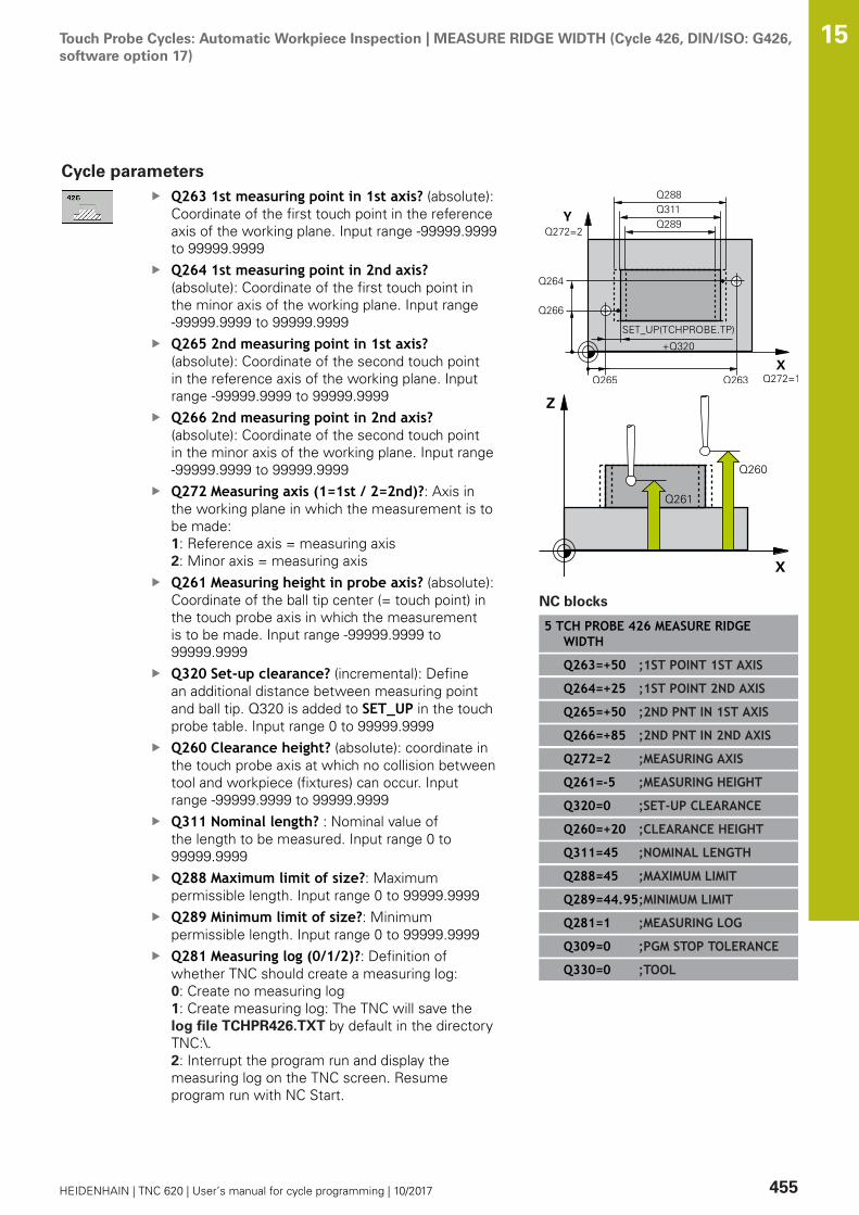
Touch Probe Cycles: Automatic Workpiece Inspection | MEASURE RIDGE WIDTH (Cycle 426, DIN/ISO: G426,software option 17)
15
HEIDENHAIN | TNC 620 | User’s manual for cycle programming | 10/2017 455
Cycle parametersQ263 1st measuring point in 1st axis? (absolute):Coordinate of the first touch point in the referenceaxis of the working plane. Input range -99999.9999to 99999.9999Q264 1st measuring point in 2nd axis?(absolute): Coordinate of the first touch point inthe minor axis of the working plane. Input range-99999.9999 to 99999.9999Q265 2nd measuring point in 1st axis?(absolute): Coordinate of the second touch pointin the reference axis of the working plane. Inputrange -99999.9999 to 99999.9999Q266 2nd measuring point in 2nd axis?(absolute): Coordinate of the second touch pointin the minor axis of the working plane. Input range-99999.9999 to 99999.9999Q272 Measuring axis (1=1st / 2=2nd)?: Axis inthe working plane in which the measurement is tobe made:1: Reference axis = measuring axis2: Minor axis = measuring axisQ261 Measuring height in probe axis? (absolute):Coordinate of the ball tip center (= touch point) inthe touch probe axis in which the measurementis to be made. Input range -99999.9999 to99999.9999Q320 Set-up clearance? (incremental): Definean additional distance between measuring pointand ball tip. Q320 is added to SET_UP in the touchprobe table. Input range 0 to 99999.9999Q260 Clearance height? (absolute): coordinate inthe touch probe axis at which no collision betweentool and workpiece (fixtures) can occur. Inputrange -99999.9999 to 99999.9999Q311 Nominal length? : Nominal value ofthe length to be measured. Input range 0 to99999.9999Q288 Maximum limit of size?: Maximumpermissible length. Input range 0 to 99999.9999Q289 Minimum limit of size?: Minimumpermissible length. Input range 0 to 99999.9999Q281 Measuring log (0/1/2)?: Definition ofwhether TNC should create a measuring log:0: Create no measuring log1: Create measuring log: The TNC will save thelog file TCHPR426.TXT by default in the directoryTNC:\.2: Interrupt the program run and display themeasuring log on the TNC screen. Resumeprogram run with NC Start.
NC blocks
5 TCH PROBE 426 MEASURE RIDGEWIDTH
Q263=+50 ;1ST POINT 1ST AXIS
Q264=+25 ;1ST POINT 2ND AXIS
Q265=+50 ;2ND PNT IN 1ST AXIS
Q266=+85 ;2ND PNT IN 2ND AXIS
Q272=2 ;MEASURING AXIS
Q261=-5 ;MEASURING HEIGHT
Q320=0 ;SET-UP CLEARANCE
Q260=+20 ;CLEARANCE HEIGHT
Q311=45 ;NOMINAL LENGTH
Q288=45 ;MAXIMUM LIMIT
Q289=44.95;MINIMUM LIMIT
Q281=1 ;MEASURING LOG
Q309=0 ;PGM STOP TOLERANCE
Q330=0 ;TOOL
Touch Probe Cycles: Automatic Workpiece Inspection | MEASURE RIDGE WIDTH (Cycle 426, DIN/ISO: G426,software option 17)
15
456 HEIDENHAIN | TNC 620 | User’s manual for cycle programming | 10/2017
Q309 PGM stop if tolerance exceeded?:Definition of whether in the event of a violation oftolerance limits the TNC is to interrupt programrun and output an error message:0: Do not interrupt program run, do not output anerror message1: Interrupt program run and output an errormessageQ330 Tool for monitoring?: Definition ofwhether the TNC is to monitor the tool (see "Toolmonitoring", Page 430). Input range 0 to 32767.9,alternatively tool name with maximum of 16characters0: Monitoring inactive>0: Number or name of the tool that the TNC usedfor machining. You are able to apply a tool via softkey directly from the tool table.

Touch Probe Cycles: Automatic Workpiece Inspection | MEASURE COORDINATE (Cycle 427, DIN/ISO: G427,software option 17)
15
HEIDENHAIN | TNC 620 | User’s manual for cycle programming | 10/2017 457
15.11 MEASURE COORDINATE (Cycle 427,DIN/ISO: G427, software option 17)
Cycle runTouch Probe Cycle 427 finds a coordinate in a selectable axisand saves the value in a system parameter. If you define thecorresponding tolerance values in the cycle, the TNC makes anominal-to-actual value comparison and saves the deviation value insystem parameters.1 Following the positioning logic, the TNC positions the touch
probe at rapid traverse (value from FMAX column) (see"Executing touch probe cycles", Page 339) to touch point 1.The TNC offsets the touch probe by the safety clearance in thedirection opposite to the defined traverse direction.
2 Then the TNC positions the touch probe to the entered touchpoint 1 in the working plane and measures the actual value inthe selected axis.
3 Finally the TNC returns the touch probe to the clearanceheight and saves the measured coordinate in the following Qparameter.
Parameter number Meaning
Q160 Measured coordinate
Please note while programming:
Before a cycle definition you must have programmed atool call to define the touch probe axis.If an axis of the active working plane is defined asmeasuring axis (Q272 = 1 or 2), the TNC compensatesthe tool radius. From the defined traversing direction(Q267) the TNC determines the direction ofcompensation.If the touch probe axis is defined as measuring axis(Q272 = 3), the TNC compensates the tool length.Parameters Q498 and Q531 have no effect in this cycle.You do not need to make any entries. These parametershave only been integrated for reasons of compatibility.If, for example, you import a program of the contouringcontrol for turning and milling, TNC 640, you will notreceive an error message.
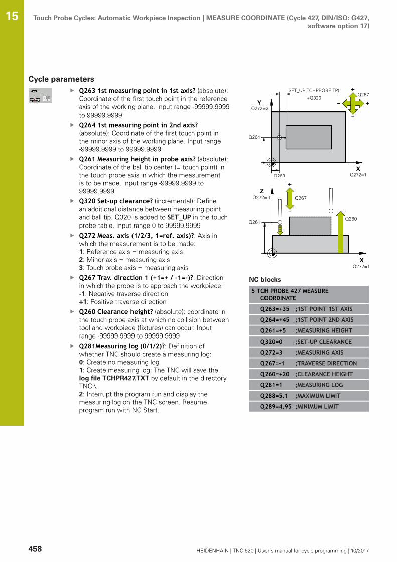
Touch Probe Cycles: Automatic Workpiece Inspection | MEASURE COORDINATE (Cycle 427, DIN/ISO: G427,software option 17)
15
458 HEIDENHAIN | TNC 620 | User’s manual for cycle programming | 10/2017
Cycle parametersQ263 1st measuring point in 1st axis? (absolute):Coordinate of the first touch point in the referenceaxis of the working plane. Input range -99999.9999to 99999.9999Q264 1st measuring point in 2nd axis?(absolute): Coordinate of the first touch point inthe minor axis of the working plane. Input range-99999.9999 to 99999.9999Q261 Measuring height in probe axis? (absolute):Coordinate of the ball tip center (= touch point) inthe touch probe axis in which the measurementis to be made. Input range -99999.9999 to99999.9999Q320 Set-up clearance? (incremental): Definean additional distance between measuring pointand ball tip. Q320 is added to SET_UP in the touchprobe table. Input range 0 to 99999.9999Q272 Meas. axis (1/2/3, 1=ref. axis)?: Axis inwhich the measurement is to be made:1: Reference axis = measuring axis2: Minor axis = measuring axis3: Touch probe axis = measuring axisQ267 Trav. direction 1 (+1=+ / -1=-)?: Directionin which the probe is to approach the workpiece:-1: Negative traverse direction+1: Positive traverse directionQ260 Clearance height? (absolute): coordinate inthe touch probe axis at which no collision betweentool and workpiece (fixtures) can occur. Inputrange -99999.9999 to 99999.9999Q281Measuring log (0/1/2)?: Definition ofwhether TNC should create a measuring log:0: Create no measuring log1: Create measuring log: The TNC will save thelog file TCHPR427.TXT by default in the directoryTNC:\.2: Interrupt the program run and display themeasuring log on the TNC screen. Resumeprogram run with NC Start.
NC blocks
5 TCH PROBE 427 MEASURECOORDINATE
Q263=+35 ;1ST POINT 1ST AXIS
Q264=+45 ;1ST POINT 2ND AXIS
Q261=+5 ;MEASURING HEIGHT
Q320=0 ;SET-UP CLEARANCE
Q272=3 ;MEASURING AXIS
Q267=-1 ;TRAVERSE DIRECTION
Q260=+20 ;CLEARANCE HEIGHT
Q281=1 ;MEASURING LOG
Q288=5.1 ;MAXIMUM LIMIT
Q289=4.95 ;MINIMUM LIMIT
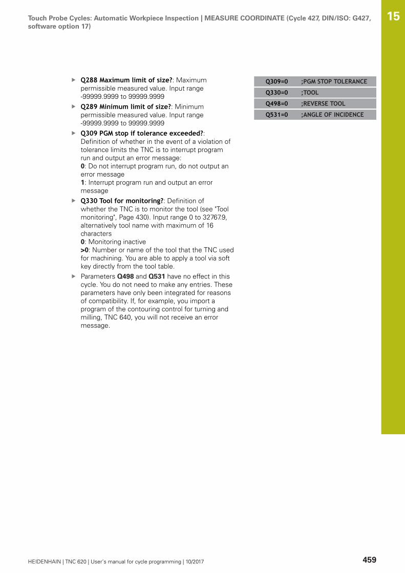
Touch Probe Cycles: Automatic Workpiece Inspection | MEASURE COORDINATE (Cycle 427, DIN/ISO: G427,software option 17)
15
HEIDENHAIN | TNC 620 | User’s manual for cycle programming | 10/2017 459
Q288 Maximum limit of size?: Maximumpermissible measured value. Input range-99999.9999 to 99999.9999Q289 Minimum limit of size?: Minimumpermissible measured value. Input range-99999.9999 to 99999.9999Q309 PGM stop if tolerance exceeded?:Definition of whether in the event of a violation oftolerance limits the TNC is to interrupt programrun and output an error message:0: Do not interrupt program run, do not output anerror message1: Interrupt program run and output an errormessageQ330 Tool for monitoring?: Definition ofwhether the TNC is to monitor the tool (see "Toolmonitoring", Page 430). Input range 0 to 32767.9,alternatively tool name with maximum of 16characters0: Monitoring inactive>0: Number or name of the tool that the TNC usedfor machining. You are able to apply a tool via softkey directly from the tool table.Parameters Q498 and Q531 have no effect in thiscycle. You do not need to make any entries. Theseparameters have only been integrated for reasonsof compatibility. If, for example, you import aprogram of the contouring control for turning andmilling, TNC 640, you will not receive an errormessage.
Q309=0 ;PGM STOP TOLERANCE
Q330=0 ;TOOL
Q498=0 ;REVERSE TOOL
Q531=0 ;ANGLE OF INCIDENCE
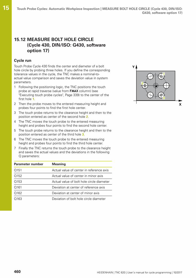
Touch Probe Cycles: Automatic Workpiece Inspection | MEASURE BOLT HOLE CIRCLE (Cycle 430, DIN/ISO:G430, software option 17)
15
460 HEIDENHAIN | TNC 620 | User’s manual for cycle programming | 10/2017
15.12 MEASURE BOLT HOLE CIRCLE(Cycle 430, DIN/ISO: G430, softwareoption 17)
Cycle runTouch Probe Cycle 430 finds the center and diameter of a bolthole circle by probing three holes. If you define the correspondingtolerance values in the cycle, the TNC makes a nominal-to-actual value comparison and saves the deviation value in systemparameters.1 Following the positioning logic, the TNC positions the touch
probe at rapid traverse (value from FMAX column) (see"Executing touch probe cycles", Page 339) to the center of thefirst hole 1.
2 Then the probe moves to the entered measuring height andprobes four points to find the first hole center.
3 The touch probe returns to the clearance height and then to theposition entered as center of the second hole 2.
4 The TNC moves the touch probe to the entered measuringheight and probes four points to find the second hole center.
5 The touch probe returns to the clearance height and then to theposition entered as center of the third hole 3.
6 The TNC moves the touch probe to the entered measuringheight and probes four points to find the third hole center.
7 Finally the TNC returns the touch probe to the clearance heightand saves the actual values and the deviations in the followingQ parameters:
Parameter number Meaning
Q151 Actual value of center in reference axis
Q152 Actual value of center in minor axis
Q153 Actual value of bolt hole circle diameter
Q161 Deviation at center of reference axis
Q162 Deviation at center of minor axis
Q163 Deviation of bolt hole circle diameter

Touch Probe Cycles: Automatic Workpiece Inspection | MEASURE BOLT HOLE CIRCLE (Cycle 430, DIN/ISO:G430, software option 17)
15
HEIDENHAIN | TNC 620 | User’s manual for cycle programming | 10/2017 461
Please note while programming:
Before a cycle definition you must have programmed atool call to define the touch probe axis.Cycle 430 only monitors for tool breakage; there is noautomatic tool compensation.
Cycle parametersQ273 Center in 1st axis (nom. value)? (absolute):Bolt hole circle center (nominal value) in thereference axis of the working plane. Input range-99999.9999 to 99999.9999Q274 Center in 2nd axis (nom. value)?(absolute): Bolt hole circle center (nominal value)in the minor axis of the working plane. Input range-99999.9999 to 99999.9999Q262 Nominal diameter?: Enter the diameter ofthe hole. Input range 0 to 99999.9999Q291 Polar coord. angle of 1st hole? (absolute):Polar coordinate angle of the first hole centerin the working plane. Input range -360.0000 to360.0000Q292 Polar coord. angle of 2nd hole? (absolute):Polar coordinate angle of the second hole centerin the working plane. Input range -360.0000 to360.0000Q292 Polar coord. angle of 3rd hole? (absolute):Polar coordinate angle of the third hole centerin the working plane. Input range -360.0000 to360.0000Q261 Measuring height in probe axis? (absolute):Coordinate of the ball tip center (= touch point) inthe touch probe axis in which the measurementis to be made. Input range -99999.9999 to99999.9999Q260 Clearance height? (absolute): coordinate inthe touch probe axis at which no collision betweentool and workpiece (fixtures) can occur. Inputrange -99999.9999 to 99999.9999Q288 Maximum limit of size?: Maximumpermissible bolt hole circle diameter. Input range 0to 99999.9999
NC blocks
5 TCH PROBE 430 MEAS. BOLT HOLECIRC
Q273=+50 ;CENTER IN 1ST AXIS
Q274=+50 ;CENTER IN 2ND AXIS
Q262=80 ;NOMINAL DIAMETER
Q291=+0 ;ANGLE OF 1ST HOLE
Q292=+90 ;ANGLE OF 2ND HOLE
Q293=+180 ;ANGLE OF 3RD HOLE
Q261=-5 ;MEASURING HEIGHT
Q260=+10 ;CLEARANCE HEIGHT
Q288=80.1 ;MAXIMUM LIMIT
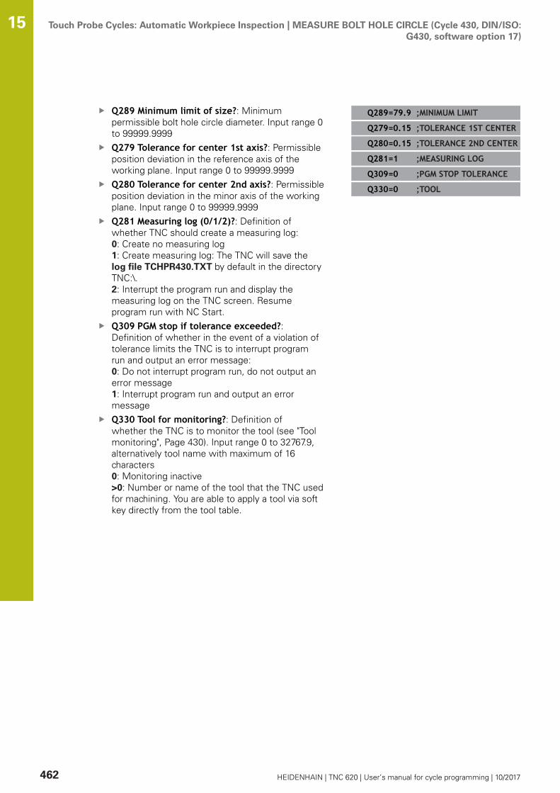
Touch Probe Cycles: Automatic Workpiece Inspection | MEASURE BOLT HOLE CIRCLE (Cycle 430, DIN/ISO:G430, software option 17)
15
462 HEIDENHAIN | TNC 620 | User’s manual for cycle programming | 10/2017
Q289 Minimum limit of size?: Minimumpermissible bolt hole circle diameter. Input range 0to 99999.9999Q279 Tolerance for center 1st axis?: Permissibleposition deviation in the reference axis of theworking plane. Input range 0 to 99999.9999Q280 Tolerance for center 2nd axis?: Permissibleposition deviation in the minor axis of the workingplane. Input range 0 to 99999.9999Q281 Measuring log (0/1/2)?: Definition ofwhether TNC should create a measuring log:0: Create no measuring log1: Create measuring log: The TNC will save thelog file TCHPR430.TXT by default in the directoryTNC:\.2: Interrupt the program run and display themeasuring log on the TNC screen. Resumeprogram run with NC Start.Q309 PGM stop if tolerance exceeded?:Definition of whether in the event of a violation oftolerance limits the TNC is to interrupt programrun and output an error message:0: Do not interrupt program run, do not output anerror message1: Interrupt program run and output an errormessageQ330 Tool for monitoring?: Definition ofwhether the TNC is to monitor the tool (see "Toolmonitoring", Page 430). Input range 0 to 32767.9,alternatively tool name with maximum of 16characters0: Monitoring inactive>0: Number or name of the tool that the TNC usedfor machining. You are able to apply a tool via softkey directly from the tool table.
Q289=79.9 ;MINIMUM LIMIT
Q279=0.15 ;TOLERANCE 1ST CENTER
Q280=0.15 ;TOLERANCE 2ND CENTER
Q281=1 ;MEASURING LOG
Q309=0 ;PGM STOP TOLERANCE
Q330=0 ;TOOL

Touch Probe Cycles: Automatic Workpiece Inspection | MEASURE PLANE (Cycle 431, DIN/ISO: G431,software option 17)
15
HEIDENHAIN | TNC 620 | User’s manual for cycle programming | 10/2017 463
15.13 MEASURE PLANE (Cycle 431,DIN/ISO: G431, software option 17)
Cycle runTouch Probe Cycle 431 finds the angle of a plane by measuringthree points. It saves the measured values in system parameters.1 Following the positioning logic, the TNC positions the touch
probe at rapid traverse (value from FMAX column) (see"Executing touch probe cycles", Page 339) to the programmedtouch point 1 and measures the first point of the plane. The TNCoffsets the touch probe by the safety clearance in the directionopposite to the direction of probing.
2 The touch probe returns to the clearance height and then movesin the working plane to starting point 2 and measures the actualvalue of the second touch point of the plane.
3 The touch probe returns to the clearance height and then movesin the working plane to starting point 3 and measures the actualvalue of the third touch point of the plane.
4 Finally the TNC returns the touch probe to the clearanceheight and saves the measured angle values in the following Qparameters:
Parameter number Meaning
Q158 Projection angle of the A axis
Q159 Projection angle of the B axis
Q170 Spatial angle A
Q171 Spatial angle B
Q172 Spatial angle C
Q173 to Q175 Measured values in the touch probeaxis (first to third measurement)

Touch Probe Cycles: Automatic Workpiece Inspection | MEASURE PLANE (Cycle 431, DIN/ISO: G431,software option 17)
15
464 HEIDENHAIN | TNC 620 | User’s manual for cycle programming | 10/2017
Please note while programming:
Before a cycle definition you must have programmed atool call to define the touch probe axis.For the TNC to be able to calculate the angular values,the three measuring points must not be positioned onone straight line.The spatial angles that are needed for tilting the workingplane are saved in parameters Q170 – Q172. With thefirst two measuring points you also specify the directionof the reference axis when tilting the working plane.The third measuring point determines the directionof the tool axis. Define the third measuring point inthe direction of the positive Y axis to ensure that theposition of the tool axis in a clockwise coordinatesystem is correct.
Cycle parametersQ263 1st measuring point in 1st axis? (absolute):Coordinate of the first touch point in the referenceaxis of the working plane. Input range -99999.9999to 99999.9999Q264 1st measuring point in 2nd axis?(absolute): Coordinate of the first touch point inthe minor axis of the working plane. Input range-99999.9999 to 99999.9999Q294 1st measuring point in 3rd axis? (absolute):Coordinate of the first touch point in thetouch probe axis. Input range -99999.9999 to99999.9999Q265 2nd measuring point in 1st axis?(absolute): Coordinate of the second touch pointin the reference axis of the working plane. Inputrange -99999.9999 to 99999.9999Q266 2nd measuring point in 2nd axis?(absolute): Coordinate of the second touch pointin the minor axis of the working plane. Input range-99999.9999 to 99999.9999Q295 2nd measuring point in 3rd axis?(absolute): Coordinate of the second touch point inthe touch probe axis. Input range -99999.9999 to99999.9999Q296 3rd measuring point in 1st axis? (absolute):Coordinate of the third touch point in the referenceaxis of the working plane. Input range -99999.9999to 99999.9999
NC blocks
5 TCH PROBE 431 MEASURE PLANE
Q263=+20 ;1ST POINT 1ST AXIS
Q264=+20 ;1ST POINT 2ND AXIS
Q294=-10 ;1ST POINT 3RD AXIS
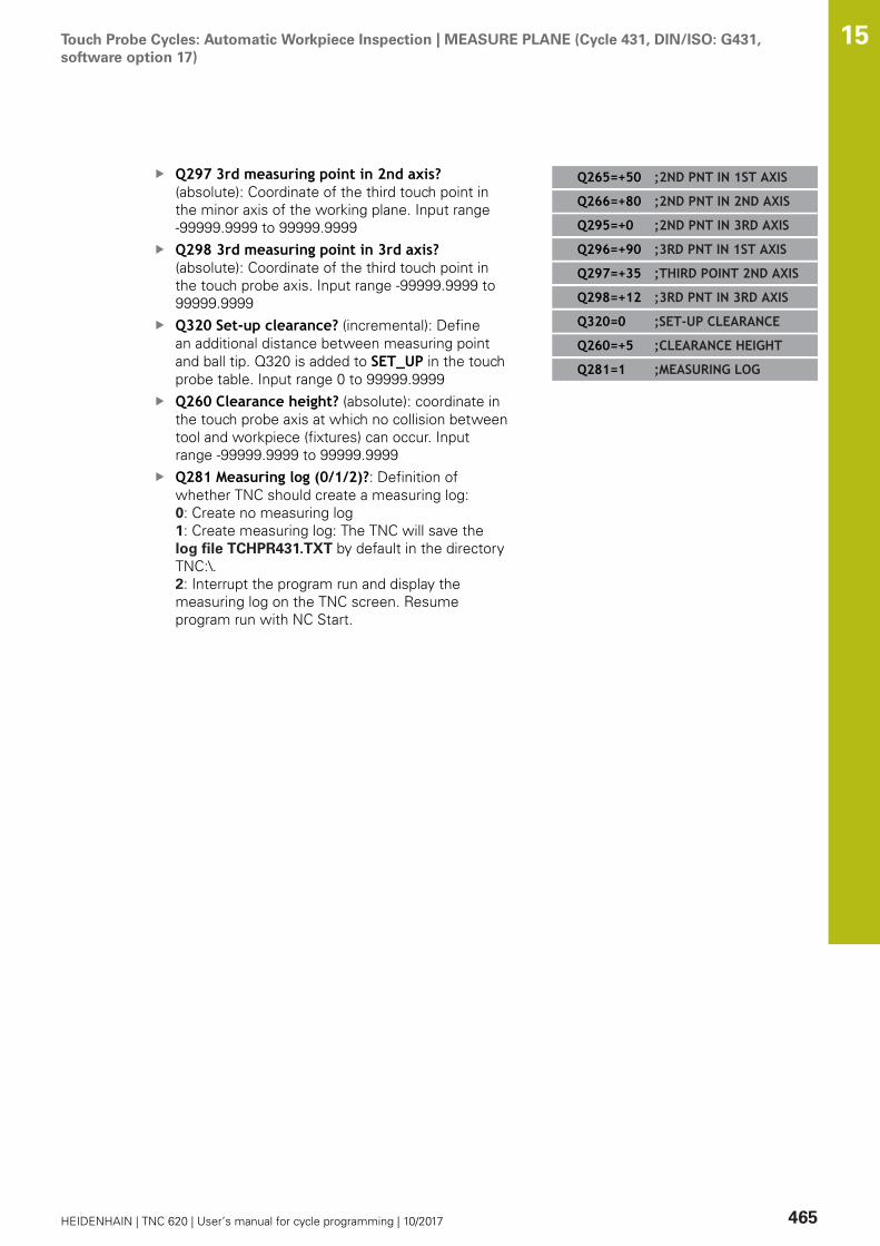
Touch Probe Cycles: Automatic Workpiece Inspection | MEASURE PLANE (Cycle 431, DIN/ISO: G431,software option 17)
15
HEIDENHAIN | TNC 620 | User’s manual for cycle programming | 10/2017 465
Q297 3rd measuring point in 2nd axis?(absolute): Coordinate of the third touch point inthe minor axis of the working plane. Input range-99999.9999 to 99999.9999Q298 3rd measuring point in 3rd axis?(absolute): Coordinate of the third touch point inthe touch probe axis. Input range -99999.9999 to99999.9999Q320 Set-up clearance? (incremental): Definean additional distance between measuring pointand ball tip. Q320 is added to SET_UP in the touchprobe table. Input range 0 to 99999.9999Q260 Clearance height? (absolute): coordinate inthe touch probe axis at which no collision betweentool and workpiece (fixtures) can occur. Inputrange -99999.9999 to 99999.9999Q281 Measuring log (0/1/2)?: Definition ofwhether TNC should create a measuring log:0: Create no measuring log1: Create measuring log: The TNC will save thelog file TCHPR431.TXT by default in the directoryTNC:\.2: Interrupt the program run and display themeasuring log on the TNC screen. Resumeprogram run with NC Start.
Q265=+50 ;2ND PNT IN 1ST AXIS
Q266=+80 ;2ND PNT IN 2ND AXIS
Q295=+0 ;2ND PNT IN 3RD AXIS
Q296=+90 ;3RD PNT IN 1ST AXIS
Q297=+35 ;THIRD POINT 2ND AXIS
Q298=+12 ;3RD PNT IN 3RD AXIS
Q320=0 ;SET-UP CLEARANCE
Q260=+5 ;CLEARANCE HEIGHT
Q281=1 ;MEASURING LOG

Touch Probe Cycles: Automatic Workpiece Inspection | Programming Examples 15
466 HEIDENHAIN | TNC 620 | User’s manual for cycle programming | 10/2017
15.14 Programming Examples
Example: Measuring and reworking a rectangular stud
Program sequence
Roughing with 0.5 mm finishing allowanceMeasuringFinishing in accordance with the measured values
0 BEGIN PGM BEAMS MM
1 TOOL CALL 69 Z Tool call for roughing
2 L Z+100 R0 FMAX Retract the tool
3 FN 0: Q1 = +81 Length of rectangle in X (roughing dimension)
4 FN 0: Q2 = +61 Length of rectangle in Y (roughing dimension)
5 CALL LBL 1 Call subprogram for machining
6 L Z+100 R0 FMAX Retract the tool, change the tool
7 TOOL CALL 99 Z Call the touch probe
8 TCH PROBE 424 MEAS. RECTAN. OUTS. Measure the rough-milled rectangle
Q273=+50 ;CENTER IN 1ST AXIS
Q274=+50 ;CENTER IN 2ND AXIS
Q282=80 ;FIRST SIDE LENGTH Nominal length in X (final dimension)
Q283=60 ;2ND SIDE LENGTH Nominal length in Y (final dimension)
Q261=-5 ;MEASURING HEIGHT
Q320=0 ;SET-UP CLEARANCE
Q260=+30 ;CLEARANCE HEIGHT
Q301=0 ;MOVE TO CLEARANCE
Q284=0 ;MAX. LIMIT 1ST SIDE Input values for tolerance checking not required
Q285=0 ;MIN. LIMIT 1ST SIDE
Q286=0 ;MAX. LIMIT 2ND SIDE
Q287=0 ;MIN. LIMIT 2ND SIDE
Q279=0 ;TOLERANCE 1ST CENTER
Q280=0 ;TOLERANCE 2ND CENTER
Q281=0 ;MEASURING LOG No measuring log transmission
Q309=0 ;PGM STOP TOLERANCE Do not output an error message
Q330=0 ;TOOL No tool monitoring
9 FN 2: Q1 = +Q1 - +Q164 Calculate length in X including the measured deviation
10 FN 2: Q2 = +Q2 - +Q165 Calculate length in Y including the measured deviation
11 L Z+100 R0 FMAX Retract the touch probe, change the tool

Touch Probe Cycles: Automatic Workpiece Inspection | Programming Examples 15
HEIDENHAIN | TNC 620 | User’s manual for cycle programming | 10/2017 467
12 TOOL CALL 1 Z S5000 Tool call for finishing
13 CALL LBL 1 Call subprogram for machining
14 L Z+100 R0 FMAX M2 Retract in the tool axis, end program
15 LBL 1 Subprogram with fixed cycle for rectangular stud
16 CYCL DEF 213 STUD FINISHING
Q200=20 ;SET-UP CLEARANCE
Q201=-10 ;DEPTH
Q206=150 ;FEED RATE FOR PLNGNG
Q202=5 ;PLUNGING DEPTH
Q207=500 ;FEED RATE FOR MILLNG
Q203=+10 ;SURFACE COORDINATE
Q204=20 ;2ND SET-UP CLEARANCE
Q216=+50 ;CENTER IN 1ST AXIS
Q217=+50 ;CENTER IN 2ND AXIS
Q218=Q1 ;FIRST SIDE LENGTH Length in X variable for roughing and finishing
Q219=Q2 ;2ND SIDE LENGTH Length in Y variable for roughing and finishing
Q220=0 ;CORNER RADIUS
Q221=0 ;ALLOWANCE IN 1ST AXS
17 CYCL CALL M3 Cycle call
18 LBL 0 End of subprogram
19 END PGM BEAMS MM

Touch Probe Cycles: Automatic Workpiece Inspection | Programming Examples 15
468 HEIDENHAIN | TNC 620 | User’s manual for cycle programming | 10/2017
Example: Measuring a rectangular pocket andrecording the results
0 BEGIN PGM BSMEAS MM
1 TOOL CALL 1 Z Tool call for touch probe
2 L Z+100 R0 FMAX Retract the touch probe
3 TCH PROBE 423 MEAS. RECTAN. INSIDE
Q273=+50 ;CENTER IN 1ST AXIS
Q274=+40 ;CENTER IN 2ND AXIS
Q282=90 ;FIRST SIDE LENGTH Nominal length in X
Q283=70 ;2ND SIDE LENGTH Nominal length in Y
Q261=-5 ;MEASURING HEIGHT
Q320=0 ;SET-UP CLEARANCE
Q260=+20 ;CLEARANCE HEIGHT
Q301=0 ;MOVE TO CLEARANCE
Q284=90.15 ;MAX. LIMIT 1ST SIDE Maximum limit in X
Q285=89.95 ;MIN. LIMIT 1ST SIDE Minimum limit in X
Q286=70.1 ;MAX. LIMIT 2ND SIDE Maximum limit in Y
Q287=69.9 ;MIN. LIMIT 2ND SIDE Minimum limit in Y
Q279=0.15 ;TOLERANCE 1ST CENTER Permissible position deviation in X
Q280=0.1 ;TOLERANCE 2ND CENTER Permissible position deviation in Y
Q281=1 ;MEASURING LOG Save measuring log to a file
Q309=0 ;PGM STOP TOLERANCE Do not display an error message in case of a toleranceviolation
Q330=0 ;TOOL No tool monitoring
4 L Z+100 R0 FMAX M2 Retract the tool, end program
5 END PGM BSMEAS MM

16Touch Probe
Cycles: SpecialFunctions

Touch Probe Cycles: Special Functions | Fundamentals 16
470 HEIDENHAIN | TNC 620 | User’s manual for cycle programming | 10/2017
16.1 Fundamentals
Overview
NOTICEDanger of collision!
Cycles for coordinate transformation must not be active duringexecution of the touch probe cycles.
Do not activate the following cycles before using touch probecycles: Cycle 7 DATUM SHIFT,Cycle 8 MIRROR IMAGE, Cycle10 ROTATION,Cycle 11 SCALING and 26 AXIS-SPECIFICSCALINGReset any coordinate transformations beforehand
The TNC must be specially prepared by the machine toolbuilder for the use of a 3-D touch probe.HEIDENHAIN only assumes liability for functionality ofthe probing cycles if HEIDENHAIN touch probes areused.
The TNC provides a cycle for the following special purpose:
Soft key Cycle Page
3 MEASURING Cycle for defining OEM cycles
471
Touch Probe Cycles: Special Functions | MEASURE (Cycle 3, software option 17) 16
HEIDENHAIN | TNC 620 | User’s manual for cycle programming | 10/2017 471
16.2 MEASURE (Cycle 3, software option 17)
Cycle runTouch Probe Cycle 3 measures any position on the workpiecein a selectable direction. Unlike other measuring cycles, Cycle 3enables you to enter the measuring range SET UP and feed rateF directly. Also, the touch probe retracts by a definable value afterdetermining the measured value MB.1 The touch probe moves from the current position at the entered
feed rate in the defined probing direction. The probing directionmust be defined in the cycle as a polar angle.
2 After the TNC has saved the position, the touch probe stops.The TNC saves the X, Y, Z coordinates of the probe-tip center inthree successive Q parameters. The TNC does not conduct anylength or radius compensations. You define the number of thefirst result parameter in the cycle.
3 Finally, the TNC moves the touch probe back by that valueagainst the probing direction that you defined in the parameterMB.
Please note while programming:
The exact behavior of Touch Probe Cycle 3 is defined byyour machine tool builder or a software manufacturerwho uses it within specific touch probe cycles.
The DIST (maximum traverse to touch point) and F(probing feed rate) touch-probe data, which are effectivein other measuring cycles, do not apply in Touch ProbeCycle 3.Remember that the TNC always writes to foursuccessive Q parameters.If the TNC was not able to determine a valid touchpoint, the program is run without error message. Inthis case the TNC assigns the value –1 to the 4th resultparameter so that you can deal with the error yourself.The TNC retracts the touch probe by no more than theretraction distance MB and does not pass the startingpoint of the measurement. This rules out any collisionduring retraction.With function FN17: SYSWRITE ID 990 NR 6 you can setwhether the cycle runs through the probe input X12 orX13.

Touch Probe Cycles: Special Functions | MEASURE (Cycle 3, software option 17) 16
472 HEIDENHAIN | TNC 620 | User’s manual for cycle programming | 10/2017
Cycle parametersParameter number for result?Enter the numberof the Q parameter to which you want the TNCto assign the first measured coordinate (X). Thevalues Y and Z are in the immediately following Qparameters. Input range 0 to 1999Probing axis?: Enter the axis in whose directionthe probe is to move and confirm with the ENTkey. Input range: X, Y or ZProbing angle?: Angle, measured from thedefined probing axis in which the touch probe isto move. Confirm with ENT. Input range -180.0000to 180.0000Maximum measuring range?: Enter the maximumdistance from the starting point by which thetouch probe may move. Confirm with ENT. Inputrange -99999.9999 to 99999.9999Feed rate measurement: Enter the measuringfeed rate in mm/min. Input range 0 to 3000.000Maximum retraction distance?: Traverse path inthe direction opposite the probing direction, afterthe stylus was deflected. The TNC returns thetouch probe to a point no farther than the startingpoint, so that there can be no collision. Input range0 to 99999.9999Reference system? (0=ACT/1=REF): Definewhether the probing direction and measuringresult should reference the current coordinatesystem (ACT, can be shifted or rotated) or themachine coordinate system (REF):0: Probe in the current system and save themeasuring result to the ACT system1: Probe in the fixed machine REF system andsave the measuring result to the ref system.Output an error message(0/1): Specify whetherthe TNC is to issue an error message if the stylusis deflected at cycle start. If mode 1 is selected,the TNC saves the value -1 in the 4th resultparameter and continues the cycle:0: Error message output1: No error message output
NC blocks
4 TCH PROBE 3.0 MEASURING
5 TCH PROBE 3.1 Q1
6 TCH PROBE 3.2 X ANGLE: +15
7 TCH PROBE 3.3 ABST +10 F100 MB1REFERENCE SYSTEM: 0
8 TCH PROBE 3.4 ERRORMODE1

Touch Probe Cycles: Special Functions | MEASURING IN 3-D (Cycle 4, software option 17) 16
HEIDENHAIN | TNC 620 | User’s manual for cycle programming | 10/2017 473
16.3 MEASURING IN 3-D (Cycle 4, softwareoption 17)
Cycle run
Cycle 4 is an auxiliary cycle that can be used for probingwith any touch probe (TS, TT or TL). The TNC does notprovide a cycle for calibrating the TS touch probe in anyprobing direction.
Touch probe cycle 4 measures any position on the workpiece inthe probing direction defined by a vector. Unlike other measuringcycles, Cycle 4 enables you to enter the measuring distance andfeed rate directly. You can also define the distance by which thetouch probe retracts after determining the measured value.1 The TNC moves from the current position at the entered
feed rate in the defined probing direction. Define the probingdirection in the cycle by using a vector (delta values in X, Y andZ)
2 After the TNC has saved the position, the TNC stops theprobing motion. The TNC saves the X, Y, Z coordinates of theprobing position in three successive Q parameters. You definethe number of the first parameter in the cycle. If you are usinga TS touch probe, the probe result is corrected by the calibratedcenter offset.
3 Finally, the TNC performs a positioning movement in thedirection opposite to the direction of probing. You define thetraverse path in parameter MB—the touch probe is moved to apoint no farther than the starting point.
Please note while programming:
The TNC retracts the touch probe by no more than theretraction distance MB and does not pass the startingpoint of the measurement. This rules out any collisionduring retraction.Ensure during pre-positioning that the TNC moves theprobe-tip center without compensation to the definedposition!Remember that the TNC always writes to foursuccessive Q parameters. If the TNC was not able todetermine a valid touch point, the 4th result parameterwill have the value –1.
Touch Probe Cycles: Special Functions | MEASURING IN 3-D (Cycle 4, software option 17) 16
474 HEIDENHAIN | TNC 620 | User’s manual for cycle programming | 10/2017
Cycle parametersParameter number for result?Enter the numberof the Q parameter to which you want the TNCto assign the first measured coordinate (X). Thevalues Y and Z are in the immediately following Qparameters. Input range 0 to 1999Relative measuring path in X?: X componentof the direction vector defining the direction inwhich the touch probe is to move. Input range-99999.9999 to 99999.9999Relative measuring path in Y?: Y componentof the direction vector defining the direction inwhich the touch probe is to move. Input range-99999.9999 to 99999.9999Relative measuring path in Z?: Z componentof the direction vector defining the direction inwhich the touch probe is to move. Input range-99999.9999 to 99999.9999Maximum measuring range?: Enter the maximumdistance from the starting point by which thetouch probe may move along the direction vector.Input range -99999.9999 to 99999.9999Feed rate measurement: Enter the measuringfeed rate in mm/min. Input range 0 to 3000.000Maximum retraction distance?: Traverse pathin the direction opposite the probing direction,after the stylus was deflected. Input range 0 to99999.9999Reference system? (0=ACT/1=REF): Specifywhether the result of probing is to be saved in theinput coordinate system (ACT), or with respect tothe machine coordinate system (REF):0: Save measuring result to the ACT system1: Save measuring result to the ref system
NC blocks
4 TCH PROBE 4.0 MEASURING IN 3-D
5 TCH PROBE 4.1 Q1
6 TCH PROBE 4.2 IX-0.5 IY-1 IZ-1
7 TCH PROBE 4.3 ABST+45 F100 MB50REFERENCE SYSTEM:0

Touch Probe Cycles: Special Functions | Calibrating a touch trigger probe 16
HEIDENHAIN | TNC 620 | User’s manual for cycle programming | 10/2017 475
16.4 Calibrating a touch trigger probeIn order to precisely specify the actual trigger point of a 3-D touchprobe, you must calibrate the touch probe, otherwise the TNCcannot provide precise measuring results.
Always calibrate a touch probe in the following cases:CommissioningStylus breakageStylus exchangeChange in the probe feed rateIrregularities caused, for example, when the machineheats upChange of active tool axis
The TNC assumes the calibration values for the activeprobe system directly after the calibration process. Theupdated tool data become effective immediately, and anew tool call is not necessary.
During calibration, the TNC finds the "effective" length of the stylusand the "effective" radius of the ball tip. To calibrate the 3-D touchprobe, clamp a ring gauge or a stud of known height and knownradius to the machine table.The TNC provides calibration cycles for calibrating the length andthe radius:
Press the TOUCH PROBE soft keyDisplay the calibration cycles: PressCALIBRATE TSSelect the calibration cycle
Calibration cycles of the TNC
Soft key Function Page
Calibrating the length 481
Measure the radius and the centeroffset using a calibration ring
483
Measure the radius and the centeroffset using a stud or a calibrationpin
485
Measure the radius and the centeroffset using a calibration sphere
477

Touch Probe Cycles: Special Functions | Displaying calibration values 16
476 HEIDENHAIN | TNC 620 | User’s manual for cycle programming | 10/2017
16.5 Displaying calibration valuesThe TNC saves the effective length and effective radius of thetouch probe in the tool table. The TNC saves the ball-tip centeroffset of the touch probe in the touch-probe table in the CAL_OF1(principal axis) and CAL_OF2 (secondary axis) columns. You candisplay the values on the screen by pressing the TOUCH PROBETABLE soft key.A measuring log is created automatically during calibration. Thelog file is named TCHPRAUTO.html. This file is stored in the samelocation as the original file. The measuring log can be displayed inthe browser on the control. If a program uses more than one cycleto calibrate the touch probe, TCHPRAUTO.html will contain all themeasuring logs. When running a touch probe cycle in the ManualOperation mode, the TNC saves the measuring log under the nameTCHPRMAN.html. This file is stored in the folder TNC: \ *.
Ensure that the tool number of the tool table andthe touch-probe number of the touch-probe table arecorrect. This is regardless of whether you want touse a touch-probe cycle in automatic mode or Manualoperation mode.
For more information, see the Chapter Touch probetable

Touch Probe Cycles: Special Functions | CALIBRATE TS (Cycle 460, DIN/ISO: G460, software option 17) 16
HEIDENHAIN | TNC 620 | User’s manual for cycle programming | 10/2017 477
16.6 CALIBRATE TS (Cycle 460,DIN/ISO: G460, software option 17)
With Cycle 460 you can calibrate a triggering 3-D touch probeautomatically on an exact calibration sphere.It is also possible to capture 3-D calibration data. Software option92, 3D-ToolComp, is required for this purpose. 3-D calibration datadescribe the deflection behavior of the touch probe in any probingdirection. The 3-D calibration data are stored under TNC:\system\CAL_TS<T-Nr.>_<T-Idx.>.3DTC. The DR2TABLE column of the tooltable refers to the 3DTC table. The 3-D calibration data are thentaken into account when probing. This 3-D calibration is necessaryif you want to achieve a very high accuracy with Cycle 444 3-DProbing (see "3D PROBING (Cycle 444), (software option 17)").Cycle run
The setting in parameter Q433 specifies whether you can performradius and length calibration, or just radius calibration.Radius calibration Q433=0
1 Clamp the calibration sphere. Ensure the prevention of collisions2 In the touch probe axis, position the touch probe over the
calibration sphere, and in the working plane, approximately overthe sphere center.
3 The TNC first moves in the plane, depending on the referenceangle (Q380).
4 The TNC then positions the touch probe in touch-probe axis.5 The probing process starts, and the TNC begins by searching for
the equator of the calibration sphere6 Once the equator has been determined, the radius calibration
begins7 Finally, the TNC returns the touch probe in the touch-probe axis
to the height at which it had been pre-positioned.

Touch Probe Cycles: Special Functions | CALIBRATE TS (Cycle 460, DIN/ISO: G460, software option 17) 16
478 HEIDENHAIN | TNC 620 | User’s manual for cycle programming | 10/2017
Radius and length calibration Q433=1
1 Clamp the calibration sphere. Ensure the prevention of collisions2 In the touch probe axis, position the touch probe over the
calibration sphere, and in the working plane, approximately overthe sphere center.
3 The TNC first moves in the plane, depending on the referenceangle (Q380).
4 The TNC then positions the touch probe in touch-probe axis.5 The probing process starts, and the TNC begins by searching for
the equator of the calibration sphere6 Once the equator has been determined, the radius calibration
begins7 Then the TNC returns the touch probe in the touch-probe axis to
the height at which it had been pre-positioned.8 The TNC ascertains the length of the touch probe at the north
pole of the calibration sphere9 At the end of the cycle the TNC returns the touch probe in
the touch-probe axis to the height at which it had been pre-positioned.
The setting in parameter Q455 specifies whether you can performan additional 3-D calibration.3-D calibration Q455= 1...30
1 Clamp the calibration sphere. Ensure the prevention of collisions2 After calibration of the radius or length, the TNC retracts the
touch probe in touch-probe axis. Then the TNC positions thetouch probe over the north pole
3 The probing process goes from the north pole to the equator inseveral steps. Deviations from the nominal value, and thereforethe specific deflection behavior, are thus determined
4 You can specify the number of probing points betweenthe north pole and the equator. This number depends oninput parameter Q455. A value between 1 and 30 can beprogrammed. If you program Q455=0, no 3-D calibration will beperformed.
5 The deviations determined during the calibration are stored in a3DTC table.
6 At the end of the cycle the TNC returns the touch probe inthe touch-probe axis to the height at which it had been pre-positioned.

Touch Probe Cycles: Special Functions | CALIBRATE TS (Cycle 460, DIN/ISO: G460, software option 17) 16
HEIDENHAIN | TNC 620 | User’s manual for cycle programming | 10/2017 479
Please note while programming:
NOTICEDanger of collision!
Cycles for coordinate transformation must not be active duringexecution of the touch probe cycles.
Do not activate the following cycles before using touch probecycles: Cycle 7 DATUM SHIFT,Cycle 8 MIRROR IMAGE, Cycle10 ROTATION,Cycle 11 SCALING and 26 AXIS-SPECIFICSCALINGReset any coordinate transformations beforehand
HEIDENHAIN only gives warranty for the function of theprobing cycles if HEIDENHAIN touch probes are used.
A measuring log is created automatically duringcalibration. The log file is named TCHPRAUTO.html. Thisfile is stored in the same location as the original file.The measuring log can be displayed in the browser onthe control. If a program uses more than one cycle tocalibrate the touch probe, TCHPRAUTO.html will containall the measuring logs.The effective length of the touch probe is alwaysreferenced to the tool reference point. The toolreference point is often on the spindle nose (and face ofthe spindle). The machine manufacturer may also placethe tool reference point at a different point.Before a cycle definition you must program a tool call todefine the touch-probe axis.Pre-position the touch probe so that it is locatedapproximately above the center of the calibrationsphere.If you program Q455=0, the TNC will not perform a 3-Dcalibration.If you program Q455=1-30, there will be a 3-Dcalibration of the touch probe. Deviations of thedeflection behavior will thus be determined undervarious angles. If you use Cycle 444, you should firstperform a 3-D calibration.If you program Q455=1-30, a table will be stored underTNC:\Table\CAL_TS<T-NR.>_<T-Idx.>.3DTC. <T-NR> isthe number of the touch probe, and <Idx> is its index.If there is already a reference to a calibration table (entryin DR2TABLE), this table will be overwritten.If there is no reference to a calibration table (entry inDR2TABLE), then, in dependence of the tool number, areference and the associated table will be created.

Touch Probe Cycles: Special Functions | CALIBRATE TS (Cycle 460, DIN/ISO: G460, software option 17) 16
480 HEIDENHAIN | TNC 620 | User’s manual for cycle programming | 10/2017
Q407 Radius of calib. sphere? Enter the exactradius of the calibration sphere used. Input range0.0001 to 99.9999Q320 Set-up clearance? (incremental): Additionaldistance between measuring point and ball tip.Q320 is added to SET_UP (touch probe table), andis only effective when the preset is probed in thetouch probe axis. Input range 0 to 99999.9999Q301 Move to clearance height (0/1)?: Definitionof how the touch probe is to move between themeasuring points:0: Move at measuring height between measuringpoints1: Move at clearance height between measuringpointsQ423 Number of probes? (absolute): Number ofmeasuring points on the diameter. Input range 0 to8Q380 Ref. angle in ref. axis? (absolute): Enterthe reference angle (basic rotation) for measuringthe measuring points in the active workpiececoordinate system. Defining a reference angle canconsiderably enlarge the measuring range of anaxis. Input range 0 to 360.0000Q433 Calibrate length (0/1)?: Define whether theTNC is to calibrate the touch probe length afterradius calibration, as well: 0: Do not calibrate touch probe length 1: Calibrate touch probe lengthQ434 Preset for length? (absolute): Coordinate ofthe calibration sphere center. The definition is onlyrequired if length calibration is to be carried out.Input range -99999.9999 to 99999.9999Q455 No. of points for 3-D calibrtn.? Enter thenumber of probing points for 3-D calibration. Avalue of about 15 probing points is useful. If 0is entered here, no 3-D calibration is performed.During 3-D calibration, the deflecting behaviorof the touch probe is determined under variousangles, and the values are stored in a table. 3D-ToolComp is required for 3-D calibration. Inputrange 1 to 30
NC blocks
5 TCH PROBE 460 CALIBRATION OF TSON A SPHERE
Q407=12.5 ;SPHERE RADIUS
Q320=0 ;SET-UP CLEARANCE
Q301=1 ;MOVE TO CLEARANCE
Q423=4 ;NO. OF PROBE POINTS
Q380=+0 ;REFERENCE ANGLE
Q433=0 ;CALIBRATE LENGTH
Q434=-2.5 ;PRESET
Q455=15 ;NO. POINTS 3-D CAL.
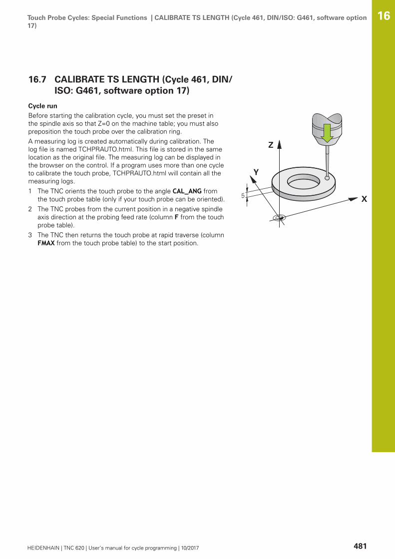
Touch Probe Cycles: Special Functions | CALIBRATE TS LENGTH (Cycle 461, DIN/ISO: G461, software option17)
16
HEIDENHAIN | TNC 620 | User’s manual for cycle programming | 10/2017 481
16.7 CALIBRATE TS LENGTH (Cycle 461, DIN/ISO: G461, software option 17)
Cycle run
Before starting the calibration cycle, you must set the preset inthe spindle axis so that Z=0 on the machine table; you must alsopreposition the touch probe over the calibration ring.A measuring log is created automatically during calibration. Thelog file is named TCHPRAUTO.html. This file is stored in the samelocation as the original file. The measuring log can be displayed inthe browser on the control. If a program uses more than one cycleto calibrate the touch probe, TCHPRAUTO.html will contain all themeasuring logs.1 The TNC orients the touch probe to the angle CAL_ANG from
the touch probe table (only if your touch probe can be oriented).2 The TNC probes from the current position in a negative spindle
axis direction at the probing feed rate (column F from the touchprobe table).
3 The TNC then returns the touch probe at rapid traverse (columnFMAX from the touch probe table) to the start position.

Touch Probe Cycles: Special Functions | CALIBRATE TS LENGTH (Cycle 461, DIN/ISO: G461, software option17)
16
482 HEIDENHAIN | TNC 620 | User’s manual for cycle programming | 10/2017
Please note while programming:
NOTICEDanger of collision!
Cycles for coordinate transformation must not be active duringexecution of the touch probe cycles.
Do not activate the following cycles before using touch probecycles: Cycle 7 DATUM SHIFT,Cycle 8 MIRROR IMAGE, Cycle10 ROTATION,Cycle 11 SCALING and 26 AXIS-SPECIFICSCALINGReset any coordinate transformations beforehand
HEIDENHAIN only gives warranty for the function of theprobing cycles if HEIDENHAIN touch probes are used.
The effective length of the touch probe is alwaysreferenced to the tool reference point. The toolreference point is often on the spindle nose (and face ofthe spindle). The machine manufacturer may also placethe tool reference point at a different point.Before a cycle definition you must have programmed atool call to define the touch probe axis.A measuring log is created automatically duringcalibration. The log file is named TCHPRAUTO.html.
Q434 Preset for length? (absolute): Referencefor the length (e.g. height of the ring gauge). Inputrange -99999.9999 to 99999.9999
NC blocks
5 TCH PROBE 461 TS CALIBRATION OFTOOL LENGTH
Q434=+5 ;PRESET

Touch Probe Cycles: Special Functions | CALIBRATE TS RADIUS INSIDE (Cycle 462, DIN/ISO: G462, softwareoption 17)
16
HEIDENHAIN | TNC 620 | User’s manual for cycle programming | 10/2017 483
16.8 CALIBRATE TS RADIUS INSIDE (Cycle462, DIN/ISO: G462, software option 17)
Cycle run
Before starting the calibration cycle, you need to preposition thetouch probe in the center of the calibration ring and at the requiredmeasuring height.When calibrating the ball tip radius, the TNC executes an automaticprobing routine. During the first probing cycle, the TNC determinesthe center of the calibration ring or stud (coarse measurement)and positions the touch probe in the center. Then the ball tipradius is determined during the actual calibration process (finemeasurement). If the touch probe allows probing from oppositeorientations, the center offset is determined during another cycle.A measuring log is created automatically during calibration. Thelog file is named TCHPRAUTO.html. This file is stored in the samelocation as the original file. The measuring log can be displayed inthe browser on the control. If a program uses more than one cycleto calibrate the touch probe, TCHPRAUTO.html will contain all themeasuring logs.The touch probe orientation determines the calibration routine:
No orientation possible or orientation possible in only onedirection: The TNC executes one approximate and one finemeasurement and determines the effective ball tip radius(column R in tool.t)Orientation possible in two directions (e.g. HEIDENHAIN touchprobes with cable): The TNC executes one approximate andone fine measurement, rotates the touch probe by 180° andthen executes four more probing operations. The center offset(CAL_OF in tchprobe.tp) is determined in addition to the radiusby probing from opposite orientations.Any orientation possible (e.g. HEIDENHAIN infrared touchprobes): For probing routine, see "orientation possible in twodirections."

Touch Probe Cycles: Special Functions | CALIBRATE TS RADIUS INSIDE (Cycle 462, DIN/ISO: G462, softwareoption 17)
16
484 HEIDENHAIN | TNC 620 | User’s manual for cycle programming | 10/2017
Please note while programming:
NOTICEDanger of collision!
Cycles for coordinate transformation must not be active duringexecution of the touch probe cycles.
Do not activate the following cycles before using touch probecycles: Cycle 7 DATUM SHIFT,Cycle 8 MIRROR IMAGE, Cycle10 ROTATION,Cycle 11 SCALING and 26 AXIS-SPECIFICSCALINGReset any coordinate transformations beforehand
Before a cycle definition you must have programmed atool call to define the touch probe axis.The center offset can be determined only with a suitabletouch probe.A measuring log is created automatically duringcalibration. The log file is named TCHPRAUTO.html.
In order to be able to determine the ball-tip centermisalignment, the TNC needs to be specially preparedby the machine manufacturer. The machine manualprovides further information.The characteristic of whether and how your touch probecan be oriented is already defined in HEIDENHAINtouch probes. Other touch probes are configured by themachine tool builder.HEIDENHAIN only gives warranty for the function of theprobing cycles if HEIDENHAIN touch probes are used.
Q407 RING RADIUS Enter the radius of the ringgauge. Input range 0 to 9.9999Q320 Set-up clearance? (incremental): Definean additional distance between measuring pointand ball tip. Q320 is added to SET_UP in the touchprobe table. Input range 0 to 99999.9999Q423 Number of probes? (absolute): Number ofmeasuring points on the diameter. Input range 0 to8Q380 Ref. angle in ref. axis? (absolute): Anglebetween the reference axis of the workingplane and the first touch point. Input range 0 to360.0000 NC blocks
5 TCH PROBE 462 CALIBRATION OF A TSIN A RING
Q407=+5 ;RING RADIUS
Q320=+0 ;SET-UP CLEARANCE
Q423=+8 ;NO. OF PROBE POINTS
Q380=+0 ;REFERENCE ANGLE
Touch Probe Cycles: Special Functions | CALIBRATE TS RADIUS OUTSIDE (Cycle 463, DIN/ISO: G463,software option 17)
16
HEIDENHAIN | TNC 620 | User’s manual for cycle programming | 10/2017 485
16.9 CALIBRATE TS RADIUS OUTSIDE (Cycle463, DIN/ISO: G463, software option 17)
Cycle run
Before starting the calibration cycle, you need to preposition thetouch probe above the center of the calibration pin. Position thetouch probe in the touch probe axis by approximately the safetyclearance (value from touch probe table + value from cycle) abovethe calibration pin.When calibrating the ball tip radius, the TNC executes an automaticprobing routine. During the first probing cycle, the TNC determinesthe center of the calibration ring or stud (coarse measurement)and positions the touch probe in the center. Then the ball tipradius is determined during the actual calibration process (finemeasurement). If the touch probe allows probing from oppositeorientations, the center offset is determined during another cycle.A measuring log is created automatically during calibration. Thelog file is named TCHPRAUTO.html. This file is stored in the samelocation as the original file. The measuring log can be displayed inthe browser on the control. If a program uses more than one cycleto calibrate the touch probe, TCHPRAUTO.html will contain all themeasuring logs.The touch probe orientation determines the calibration routine:
No orientation possible or orientation possible in only onedirection: The TNC executes one approximate and one finemeasurement and determines the effective ball tip radius(column R in tool.t)Orientation possible in two directions (e.g. HEIDENHAIN touchprobes with cable): The TNC executes one approximate andone fine measurement, rotates the touch probe by 180° andthen executes four more probing operations. The center offset(CAL_OF in tchprobe.tp) is determined in addition to the radiusby probing from opposite orientations.Any orientation possible (e.g. HEIDENHAIN infrared touchprobes): For probing routine, see "orientation possible in twodirections."

Touch Probe Cycles: Special Functions | CALIBRATE TS RADIUS OUTSIDE (Cycle 463, DIN/ISO: G463,software option 17)
16
486 HEIDENHAIN | TNC 620 | User’s manual for cycle programming | 10/2017
Please note while programming:
NOTICEDanger of collision!
Cycles for coordinate transformation must not be active duringexecution of the touch probe cycles.
Do not activate the following cycles before using touch probecycles: Cycle 7 DATUM SHIFT,Cycle 8 MIRROR IMAGE, Cycle10 ROTATION,Cycle 11 SCALING and 26 AXIS-SPECIFICSCALINGReset any coordinate transformations beforehand
Before a cycle definition you must have programmed atool call to define the touch probe axis.The center offset can be determined only with a suitabletouch probe.A measuring log is created automatically duringcalibration. The log file is named TCHPRAUTO.html.
In order to be able to determine the ball-tip centermisalignment, the TNC needs to be specially preparedby the machine manufacturer. The machine manualprovides further information.The characteristic of whether and how your touch probecan be oriented is already defined in HEIDENHAINtouch probes. Other touch probes are configured by themachine tool builder.HEIDENHAIN only gives warranty for the function of theprobing cycles if HEIDENHAIN touch probes are used.
Q407 Radius of calibr. stud?: Diameter of the ringgauge. Input range 0 to 99.9999Q320 Set-up clearance? (incremental): Definean additional distance between measuring pointand ball tip. Q320 is added to SET_UP in the touchprobe table. Input range 0 to 99999.9999Q301 Move to clearance height (0/1)?: Definitionof how the touch probe is to move between themeasuring points:0: Move at measuring height between measuringpoints1: Move at clearance height between measuringpointsQ423 Number of probes? (absolute): Number ofmeasuring points on the diameter. Input range 0 to8Q380 Ref. angle in ref. axis? (absolute): Anglebetween the reference axis of the workingplane and the first touch point. Input range 0 to360.0000
NC blocks
5 TCH PROBE 463 TS CALIBRATION ONSTUD
Q407=+5 ;STUD RADIUS
Q320=+0 ;SET-UP CLEARANCE
Q301=+1 ;MOVE TO CLEARANCE
Q423=+8 ;NO. OF PROBE POINTS
Q380=+0 ;REFERENCE ANGLE
Touch Probe Cycles: Special Functions | FAST PROBING (Cycle 441, DIN/ISO G441, software option 17) 16
HEIDENHAIN | TNC 620 | User’s manual for cycle programming | 10/2017 487
16.10 FAST PROBING (Cycle 441, DIN/ISOG441, software option 17)
Cycle runYou can use the touch probe cycle 441 to globally specify varioustouch probe parameters (e.g. the positioning feed rate) for allsubsequently used touch probe cycles.
Please note while programming:
Cycle 441 sets parameters for touch probe cycles. Thiscycle does not perform machine movementsEND PGM, M2, M30 resets the global settings of Cycle441.Cycle parameter Q399 depends on your machineconfiguration. Orienting the touch probe system viathe NC program must be enabled by your machine toolbuilder.The feed rate can also be limited by your machine toolbuilder. The absolute maximum feed rate is defined inthe machine parameter maxTouchFeed (No. 122602).Even if your machine has separate potentiometers forrapid traverse and feed rate, you can control the feedrate, also with Q397=1, only with the potentiometer forfeed motions.

Touch Probe Cycles: Special Functions | FAST PROBING (Cycle 441, DIN/ISO G441, software option 17) 16
488 HEIDENHAIN | TNC 620 | User’s manual for cycle programming | 10/2017
Cycle parametersQ396 Positioning feed rate?: Define the feedrate at which the TNC executes positioningmovements of the touch probe. Input range 0 to99999.9999, alternatively FMAX, FAUTOQ397 Pre-pos. at machine's rapid?: Definewhether the TNC, when pre-positioning thetouch probe, traverses with the FMAX feed rate(machine's rapid traverse): 0: Pre-position with feed rate from Q3961: Pre-position with machine's rapid traverseFMAXEven if your machine has separatepotentiometers for rapid traverse and feed rate,you can control the feed rate, also with Q397=1,only with the potentiometer for feed motions.The feed rate can also be limited by your machinetool builder. The absolute maximum feed rate isdefined in the machine parameter maxTouchFeed(No. 122602).Q399 Angle tracking (0/1)?: Define whether theTNC orients the touch probe before each probingprocess:0: No orientation 1: Orient spindle before each probing process(improves the accuracy)Q400 Automatic interruption? Define whetherthe TNC following a measuring cycle for automaticworkpiece measurement interrupts the programrun and outputs the measuring results to thescreen:0: Do not interrupt program run even if in thespecific probing cycle the output of measuringresults to the screen is selected1: Interrupt program run and output measuringresults to the screen. Program run can then becontinued with NC start
NC blocks
5 TCH PROBE 441 FAST PROBING
Q 396=3000;POSITIONING FEED RATE
Q 397=0 ;SELECT FEED RATE
Q 399=1 ;ANGLE TRACKING
Q 400=1 ;INTERRUPTION

17Touch Probe
Cycles: AutomaticKinematics
Measurement

Touch Probe Cycles: Automatic Kinematics Measurement | Kinematics measurement with TS touch probes(KinematicsOpt option)
17
490 HEIDENHAIN | TNC 620 | User’s manual for cycle programming | 10/2017
17.1 Kinematics measurement with TS touchprobes (KinematicsOpt option)
FundamentalsAccuracy requirements are becoming increasingly stringent,particularly in the area of 5-axis machining. Complex parts need tobe manufactured with precision and reproducible accuracy evenover long periods.Some of the reasons for inaccuracy in multi-axis machining aredeviations between the kinematic model saved in the control(see 1 in the figure at right), and the kinematic conditions actuallyexisting on the machine (see 2 in the figure at right). When therotary axes are positioned, these deviations cause inaccuracy ofthe workpiece (see 3 in the figure at right). It is therefore necessaryfor the model to approach reality as closely as possible.The TNC function KinematicsOpt is an important componentthat helps you to really fulfill these complex requirements: a 3-Dtouch probe cycle measures the rotary axes on your machine fullyautomatically, regardless of whether they are in the form of tablesor spindle heads. A calibration sphere is fixed at any position onthe machine table, and measured with a resolution that you define.During cycle definition you simply define for each rotary axis thearea that you want to measure.From the measured values, the TNC calculates the static tiltingaccuracy. The software minimizes the positioning error arisingfrom the tilting movements and, at the end of the measurementprocess, automatically saves the machine geometry in therespective machine constants of the kinematic table.
OverviewThe TNC offers cycles that enable you to automatically save, checkand optimize the machine kinematics:
Soft key Cycle Page
450 SAVE KINEMATICSAutomatic saving and restoring ofkinematic configurations
493
451 MEASURE KINEMATICSAutomatic checking or optimizing themachine kinematics
496
452 PRESET COMPENSATIONAutomatic checking or optimizing themachine kinematics
510

Touch Probe Cycles: Automatic Kinematics Measurement | Prerequisites 17
HEIDENHAIN | TNC 620 | User’s manual for cycle programming | 10/2017 491
17.2 PrerequisitesThe following are prerequisites for using the KinematicsOpt option:
The software options 48 (KinematicsOpt), 8 (Software option 1)and 17 (Touch Probe function) must be enabled.The 3-D touch probe used for the measurement must becalibrated.The cycles can only be carried out with the tool axis Z.A calibration sphere with an exactly known radius and sufficientrigidity must be attached to any position on the machine table.HEIDENHAIN recommends using the calibration spheresKKH 250 (ID number 655475-01) or KKH 100 (ID number655475-02), which have particularly high rigidity and aredesigned especially for machine calibration. Please contactHEIDENHAIN if you have any questions in this regard.The kinematics description of the machine must be completeand correct. The transformation values must be entered with anaccuracy of approx. 1 mm.The complete machine geometry must have been measured (bythe machine tool builder during commissioning).The machine tool builder must have defined the machineparameters for CfgKinematicsOpt (No. 204800) in theconfiguration data. maxModification (No. 204801) specifiesthe tolerance limit starting from which the TNC is to displaya message if the changes to the kinematic data exceed thislimit value. maxDevCalBall (No. 204802) defines how much themeasured radius of the calibration sphere may deviate fromthe entered cycle parameter. mStrobeRotAxPos (No. 204803)defines an M function that is specifically configured by themachine manufacturer and is used to position the rotary axes.
Touch Probe Cycles: Automatic Kinematics Measurement | Prerequisites 17
492 HEIDENHAIN | TNC 620 | User’s manual for cycle programming | 10/2017
Please note while programming:
NOTICEDanger of collision!
Cycles for coordinate transformation must not be active duringexecution of the touch probe cycles.
Do not activate the following cycles before using touch probecycles: Cycle 7 DATUM SHIFT,Cycle 8 MIRROR IMAGE, Cycle10 ROTATION,Cycle 11 SCALING and 26 AXIS-SPECIFICSCALINGReset any coordinate transformations beforehand
HEIDENHAIN only gives warranty for the function of theprobing cycles if HEIDENHAIN touch probes are used.
If an M function has been defined in machine parametermStrobeRotAxPos (No. 204803), you have to positionthe rotary axes to 0° (ACTUAL system) before startingone of the KinematicsOpt cycles (except for 450).If machine parameters were changed through theKinematicsOpt cycles, the control must be restarted.Otherwise the changes could be lost in certaincircumstances.

Touch Probe Cycles: Automatic Kinematics Measurement | SAVE KINEMATICS (Cycle 450, DIN/ISO: G450,option)
17
HEIDENHAIN | TNC 620 | User’s manual for cycle programming | 10/2017 493
17.3 SAVE KINEMATICS (Cycle 450, DIN/ISO:G450, option)
Cycle runWith Touch Probe Cycle 450 you can save the active machinekinematic configuration or restore a previously saved one. Thesaved data can be displayed and deleted. 16 memory spaces intotal are available.
Please note while programming:
Always save the active kinematics configuration beforerunning a kinematics optimization. Advantage:
You can restore the old data if you are not satisfiedwith the results or if errors occur during optimization(e.g. power failure).
With the Restore mode, note thatthe TNC can restore saved data only to a matchingkinematic configuration.a change in the kinematics always changes thepreset as well. Set the preset again if necessary.
Saving and restoring with Cycle 450 should onlybe performed if no tool carrier kinematics withtransformations is active

Touch Probe Cycles: Automatic Kinematics Measurement | SAVE KINEMATICS (Cycle 450, DIN/ISO: G450,option)
17
494 HEIDENHAIN | TNC 620 | User’s manual for cycle programming | 10/2017
Cycle parametersQ410 Mode (0/1/2/3)?: Define if you wish tobackup or restore the kinematics:0: Backup active kinematics1: Restore saved kinematics2: Display current memory status3: Delete a data recordQ409/QS409 Name of data record?: Number orname of the data block designator. For numbersyou can enter values from 0 to 99999, and whenentering letters the string length may be no longerthan 16 characters 16 memory spaces in totalare available. Q409 has no function if Mode 2has been selected. Wildcards can be used forsearches in Modes 1 and 3 (Restore and Delete).If the TNC finds several possible data recordsbecause of the wildcards, the TNC restores themean values of the data (Mode 1) or deletes alldata blocks after confirmation (Mode 3). You canuse the following wildcards for searching:?: A single indefinite character$: A single alphabetic character (letter)#: A single indefinite number*: An indefinite character string of any length
Saving the current kinematics
5 TCH PROBE 450 SAVE KINEMATICS
Q410=0 ;MODE
Q409=947 ;MEMORY DESIGNATION
Restoring data blocks
5 TCH PROBE 450 SAVE KINEMATICS
Q410=1 ;MODE
Q409=948 ;MEMORY DESIGNATION
Displaying all saved data blocks
5 TCH PROBE 450 SAVE KINEMATICS
Q410=2 ;MODE
Q409=949 ;MEMORY DESIGNATION
Deleting data blocks
5 TCH PROBE 450 SAVE KINEMATICS
Q410=3 ;MODE
Q409=950 ;MEMORY DESIGNATION
Logging functionAfter running Cycle 450, the TNC will create a measuring log(tchprAUTO.html) containing the following information:
Creation date and time of the logName of the NC program from which the cycle was runDesignator of the current kinematicsActive tool
The other data in the log vary depending on the selected mode:Mode 0: Logging of all axis entries and transformation entries ofthe kinematics chain that the TNC has saved.Mode 1: Logging of all transformation entries before and afterrestoring the kinematics configuration.Mode 2: List of the saved data records.Mode 3: List of the deleted data records.
Touch Probe Cycles: Automatic Kinematics Measurement | SAVE KINEMATICS (Cycle 450, DIN/ISO: G450,option)
17
HEIDENHAIN | TNC 620 | User’s manual for cycle programming | 10/2017 495
Notes on data managementThe TNC stores the saved data in the file TNC:\table\DATA450.KD.This file can be backed up on an external PC with TNCremo, forexample. If the file is deleted, the stored data are removed, too.If the data in the file are changed manually, the data records canbecome corrupted so that they cannot be used anymore.
If the TNC:\table\DATA450.KD file does not exist, it isgenerated automatically when Cycle 450 is executed.Make sure that you delete empty files with the nameTNC:\table\DATA450.KD, if any, before starting Cycle450. If there is an empty storage table (TNC:\table\DATA450.KD) that does not contain any lines yet, anerror message will be displayed upon starting to runCycle 450. In this case, delete the empty storage tableand call the cycle again.Do not change stored data manually.Make a backup of the TNC:\table\DATA450.KD file sothat you can restore the file, if necessary (e.g. if the datamedium is damaged).

Touch Probe Cycles: Automatic Kinematics Measurement | MEASURE KINEMATICS (Cycle 451, DIN/ISO:G451, option)
17
496 HEIDENHAIN | TNC 620 | User’s manual for cycle programming | 10/2017
17.4 MEASURE KINEMATICS (Cycle 451, DIN/ISO: G451, option)
Cycle runTouch Probe Cycle 451 enables you to check and, if required,optimize the kinematics of your machine. Use the 3-D TS touchprobe to measure a HEIDENHAIN calibration sphere that you haveattached to the machine table.
HEIDENHAIN recommends using the calibrationspheres KKH 250 (ID number 655 475-01) or KKH100 (ID number 655 475-02), which have particularlyhigh rigidity and are designed especially for machinecalibration. Please contact HEIDENHAIN if you have anyquestions in this regard.
The TNC evaluates the static tilting accuracy. The softwareminimizes the spatial error arising from the tilting movements and,at the end of the measurement process, automatically saves themachine geometry in the respective machine constants of thekinematics description.1 Clamp the calibration sphere and check for potential collisions.2 In the Manual Operation mode, set the preset in the center
of the sphere or, if Q431=1 or Q431=3 is defined: Manuallyposition the touch probe over the calibration sphere in the touchprobe axis, and in the center of the sphere in the working plane.
3 Select the Program Run mode and start the calibration program.4 The TNC automatically measures all three axes successively in
the resolution you defined.5 The TNC saves the measured values in the following Q
parameters:

Touch Probe Cycles: Automatic Kinematics Measurement | MEASURE KINEMATICS (Cycle 451, DIN/ISO:G451, option)
17
HEIDENHAIN | TNC 620 | User’s manual for cycle programming | 10/2017 497
Parameternumber
Meaning
Q141 Standard deviation measured in the A axis(–1 if axis was not measured)
Q142 Standard deviation measured in the B axis(–1 if axis was not measured)
Q143 Standard deviation measured in the C axis(–1 if axis was not measured)
Q144 Optimized standard deviation in the A axis(–1 if axis was not optimized)
Q145 Optimized standard deviation in the B axis(–1 if axis was not optimized)
Q146 Optimized standard deviation in the C axis(–1 if axis was not optimized)
Q147 Offset error in X direction, for manual trans-fer to the corresponding machine parameter
Q148 Offset error in Y direction, for manual trans-fer to the corresponding machine parameter
Q149 Offset error in Z direction, for manual trans-fer to the corresponding machine parameter

Touch Probe Cycles: Automatic Kinematics Measurement | MEASURE KINEMATICS (Cycle 451, DIN/ISO:G451, option)
17
498 HEIDENHAIN | TNC 620 | User’s manual for cycle programming | 10/2017
Positioning directionThe positioning direction of the rotary axis to be measured isdetermined from the start angle and the end angle that you definein the cycle. A reference measurement is automatically performedat 0°.Specify the start and end angles to ensure that the same positionis not measured twice. A duplicated point measurement (e.g.measuring positions +90° and –270°) is not advisable, but it doesnot cause an error message.
Example: Start angle = +90°, end angle = –90°Start angle = +90°End angle = –90°No. of measuring points = 4Stepping angle resulting from the calculation = (-90° - +90°) /(4–1) = -60°Measuring point 1 = +90°Measuring point 2 = +30°Measuring point 3 = -30°Measuring point 4 = -90°
Example: start angle = +90°, end angle = +270°Start angle = +90°End angle = +270°No. of measuring points = 4Stepping angle resulting from the calculation = (270° – 90°) /(4–1) = +60°Measuring point 1 = +90°Measuring point 2 = +150°Measuring point 3 = +210°Measuring point 4 = +270°

Touch Probe Cycles: Automatic Kinematics Measurement | MEASURE KINEMATICS (Cycle 451, DIN/ISO:G451, option)
17
HEIDENHAIN | TNC 620 | User’s manual for cycle programming | 10/2017 499
Machines with Hirth-coupled axes
NOTICEDanger of collision!
In order to be positioned, the axis must move out of the Hirthcoupling. If necessary, the TNC rounds the calculated measuringpositions so that they fit into the Hirth grid (depending on thestart angle, end angle and number of measuring points).
So remember to leave a large enough safety clearance toprevent any risk of collision between the touch probe andcalibration sphereAlso ensure that there is enough space to reach the safetyclearance (software limit switch)
NOTICEDanger of collision!
Depending on the machine configuration, the TNC cannotposition the rotary axes automatically. If this is the case, youneed a special M function from the machine tool builder enablingthe TNC to move the rotary axes. The machine tool buildermust have entered the number of the M function in machineparameter mStrobeRotAxPos (No. 244803) for this purpose.
Note the documentation of the machine tool builder
Define a retraction height Q408 greater than 0 if software option 2(M128, FUNCTION TCPM) is not available.The measuring positions are calculated from the start angle, endangle and number of measurements for the respective axis andfrom the Hirth grid.
Example calculation of measuring positions for an A axis:
Start angle Q411 = –30End angle Q412 = +90Number of measuring points Q414 = 4Hirth grid = 3°Calculated stepping angle = (Q412 – Q411) / (Q414 – 1)Calculated stepping angle = (90° - (-30°)) / (4 – 1) = 120 / 3 = 40°Measuring position 1 = Q411 + 0 * stepping angle = -30° --> -30°Measuring position 2 = Q411 + 1 * stepping angle = +10° --> 9°Measuring position 3 = Q411 + 2 * stepping angle = +50° --> 51°Measuring position 4 = Q411 + 3 * stepping angle = +90° --> 90°
Touch Probe Cycles: Automatic Kinematics Measurement | MEASURE KINEMATICS (Cycle 451, DIN/ISO:G451, option)
17
500 HEIDENHAIN | TNC 620 | User’s manual for cycle programming | 10/2017
Choice of number of measuring pointsTo save time you can make a rough optimization with a smallnumber of measuring points (1 or 2), for example duringcommissioning.You then make a fine optimization with a medium number ofmeasuring points (recommended value = approx. 4). Highernumbers of measuring points do not usually improve the results.Ideally, you should distribute the measuring points evenly over thetilting range of the axis.This is why you should measure an axis with a tilting range of 0°to 360° at three measuring points, namely at 90°, 180° and 270°.Thus, define a starting angle of 90° and an end angle of 270°.If you want to check the accuracy accordingly, you can also enter ahigher number of measuring points in the Check mode.
If a measuring point has been defined at 0°, it will beignored because the reference measurement is alwaysdone at 0°.

Touch Probe Cycles: Automatic Kinematics Measurement | MEASURE KINEMATICS (Cycle 451, DIN/ISO:G451, option)
17
HEIDENHAIN | TNC 620 | User’s manual for cycle programming | 10/2017 501
Choice of the calibration sphere position on themachine tableIn principle, you can fix the calibration sphere to any accessibleposition on the machine table and also on fixtures or workpieces.The following factors should positively influence the result ofmeasurement:
On machine with rotary tables/tilting tables: Clamp thecalibrating ball as far as possible away from the center ofrotation.On machines with very large traverse paths: Clamp thecalibration sphere as closely as possible to the position intendedfor subsequent machining.
Notes on the accuracyThe geometrical and positioning errors of the machine influencethe measured values and therefore also the optimization of a rotaryaxis. For this reason there will always be a certain amount of error.If there were no geometrical and positioning errors, any valuesmeasured by the cycle at any point on the machine at a certaintime would be exactly reproducible. The greater the geometricaland positioning errors are, the greater is the dispersion ofmeasured results when you perform measurements at differentpositions.The dispersion of results recorded by the TNC in the measuring logis a measure of the machine's static tilting accuracy. However, themeasuring circle radius and the number and position of measuringpoints have to be included in the evaluation of accuracy. Onemeasuring point alone is not enough to calculate dispersion. Foronly one point, the result of the calculation is the spatial error ofthat measuring point.If several rotary axes are moved simultaneously, their error valuesare combined. In the worst case they are added together.
If your machine is equipped with a controlled spindle,you should activate the angle tracking in the touch probetable (TRACK column). This generally increases theaccuracy of measurements with a 3-D touch probe.If required, deactivate the lock on the rotary axes forthe duration of the calibration. Otherwise it may falsifythe results of measurement. The machine tool manualprovides further information.

Touch Probe Cycles: Automatic Kinematics Measurement | MEASURE KINEMATICS (Cycle 451, DIN/ISO:G451, option)
17
502 HEIDENHAIN | TNC 620 | User’s manual for cycle programming | 10/2017
Notes on various calibration methodsRough optimization during commissioning after enteringapproximate dimensions.
Number of measuring points between 1 and 2Angular step of the rotary axes: Approx. 90°
Fine optimization over the entire range of traverse
Number of measuring points between 3 and 6The start and end angles should cover the largest possibletraverse range of the rotary axes.Position the calibration sphere on the machine table so thaton rotary table axes there is a large measuring circle, or sothat on swivel head axes the measurement can be made ata representative position (e.g. in the center of the traverserange).
Optimization of a specific rotary axis position
Number of measuring points between 2 and 3The measurements are made near the rotary axis angle atwhich the workpiece is to be machined.Position the calibration sphere on the machine table forcalibration at the position subsequently intended formachining.
Inspecting the machine accuracy
Number of measuring points between 4 and 8The start and end angles should cover the largest possibletraverse range of the rotary axes.
Determination of the rotary axis backlash
Number of measuring points between 8 and 12The start and end angles should cover the largest possibletraverse range of the rotary axes.

Touch Probe Cycles: Automatic Kinematics Measurement | MEASURE KINEMATICS (Cycle 451, DIN/ISO:G451, option)
17
HEIDENHAIN | TNC 620 | User’s manual for cycle programming | 10/2017 503
BacklashBacklash is a small amount of play between the rotary or angleencoder and the table that occurs when the traverse direction isreversed. If the rotary axes have backlash outside of the controlloop, for example because the angle measurement is made withthe motor encoder, this can result in significant error during tilting.With input parameter Q432 you can activate backlashmeasurement. Enter an angle that the TNC uses as traversingangle. The cycle will then carry out two measurements per rotaryaxis. If you take over the angle value 0, the TNC will not measureany backlash.
The TNC does not perform an automatic backlashcompensation.If the measuring circle radius is < 1 mm, the TNCdoes not calculate the backlash. The larger themeasuring circle radius, the more accurately the TNCcan determine the rotary axis backlash (see "Loggingfunction", Page 509).Backlash measurement is not possible if an M functionis set for positioning the rotary axes in machineparameter mStrobeRotAxPos (No. 204803) or if the axisis a Hirth axis.
Touch Probe Cycles: Automatic Kinematics Measurement | MEASURE KINEMATICS (Cycle 451, DIN/ISO:G451, option)
17
504 HEIDENHAIN | TNC 620 | User’s manual for cycle programming | 10/2017
Please note while programming:
Before starting the cycle make sure that M128 orFUNCTION TCPM is deactivated.Cycle 453, as with 451 and 452, is exited with an active3-D ROT in automatic mode that matches the position ofthe rotary axes.Position the calibration sphere on the machine table sothat there can be no collisions during the measuringprocess.Before defining the cycle you must set the preset in thecenter of the calibration sphere and activate it, or youdefine the input parameter Q431 correspondingly to 1 or3.If machine parameter mStrobeRotAxPos (No. 204803)is not equal to –1 (M function positions the rotary axis),only start a measurement if all rotary axes are at 0°.For the positioning feed rate when moving to theprobing height in the touch probe axis, the TNC uses thevalue from cycle parameter Q253 or the FMAX value,whichever is smaller. The TNC always moves the rotaryaxes at positioning feed rate Q253, while the probemonitoring is inactive.The TNC ignores cycle definition data that applies toinactive axes.If you interrupt the cycle during the measurement,the kinematic data might no longer be in the originalcondition. Save the active kinematic configurationbefore an optimization with Cycle 450, so that in caseof an emergency the most recently active kinematicconfiguration can be restored.For angle optimization, the machine manufacturer musthave adapted the configuration correspondingly. Angleoptimization can be particularly useful on small, compactmachines.Compensation of the angle is only possible with option#52 KinematicsComp.
If the kinematic data attained in the Optimize mode aregreater than the permissible limit (maxModification),the TNC shows a warning. Then you have to confirmacceptance of the attained value by pressing NC start.Note that a change in the kinematics always changesthe preset as well. After an optimization, reset thepreset.In every probing process the TNC first measuresthe radius of the calibration sphere. If the measuredsphere radius differs from the entered sphere radiusby more than you have defined in machine parametermaxDevCalBall (No. 204802) the TNC shows an errormessage and ends the measurement.Programming in inches: The TNC always records the logdata and results of measurement in millimeters.
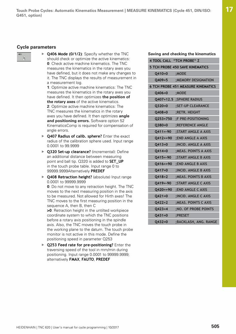
Touch Probe Cycles: Automatic Kinematics Measurement | MEASURE KINEMATICS (Cycle 451, DIN/ISO:G451, option)
17
HEIDENHAIN | TNC 620 | User’s manual for cycle programming | 10/2017 505
Cycle parametersQ406 Mode (0/1/2): Specify whether the TNCshould check or optimize the active kinematics:0: Check active machine kinematics. The TNCmeasures the kinematics in the rotary axes youhave defined, but it does not make any changes toit. The TNC displays the results of measurement ina measurement log.1: Optimize active machine kinematics: The TNCmeasures the kinematics in the rotary axes youhave defined. It then optimizes the position ofthe rotary axes of the active kinematics.2: Optimize active machine kinematics: TheTNC measures the kinematics in the rotaryaxes you have defined. It then optimizes angleand positioning errors. Software option 52KinematicsComp is required for compensation ofangle errors.Q407 Radius of calib. sphere? Enter the exactradius of the calibration sphere used. Input range0.0001 to 99.9999Q320 Set-up clearance? (incremental): Definean additional distance between measuringpoint and ball tip. Q320 is added to SET_UPin the touch probe table. Input range 0 to99999.9999Alternatively PREDEFQ408 Retraction height? (absolute) Input range0.0001 to 99999.99990: Do not move to any retraction height. The TNCmoves to the next measuring position in the axisto be measured. Not allowed for Hirth axes! TheTNC moves to the first measuring position in thesequence A, then B, then C>0: Retraction height in the untilted workpiececoordinate system to which the TNC positionsbefore a rotary axis positioning in the spindleaxis. Also, the TNC moves the touch probe inthe working plane to the datum. The touch probemonitor is not active in this mode. Define thepositioning speed in parameter Q253Q253 Feed rate for pre-positioning? Enter thetraversing speed of the tool in mm/min duringpositioning. Input range 0.0001 to 99999.9999;alternatively FMAX, FAUTO, PREDEF
Saving and checking the kinematics
4 TOOL CALL “TCH PROBE“ Z
5 TCH PROBE 450 SAVE KINEMATICS
Q410=0 ;MODE
Q409=5 ;MEMORY DESIGNATION
6 TCH PROBE 451 MEASURE KINEMATICS
Q406=0 ;MODE
Q407=12.5 ;SPHERE RADIUS
Q320=0 ;SET-UP CLEARANCE
Q408=0 ;RETR. HEIGHT
Q253=750 ;F PRE-POSITIONING
Q380=0 ;REFERENCE ANGLE
Q411=-90 ;START ANGLE A AXIS
Q412=+90 ;END ANGLE A AXIS
Q413=0 ;INCID. ANGLE A AXIS
Q414=0 ;MEAS. POINTS A AXIS
Q415=-90 ;START ANGLE B AXIS
Q416=+90 ;END ANGLE B AXIS
Q417=0 ;INCID. ANGLE B AXIS
Q418=2 ;MEAS. POINTS B AXIS
Q419=-90 ;START ANGLE C AXIS
Q420=+90 ;END ANGLE C AXIS
Q421=0 ;INCID. ANGLE C AXIS
Q422=2 ;MEAS. POINTS C AXIS
Q423=4 ;NO. OF PROBE POINTS
Q431=0 ;PRESET
Q432=0 ;BACKLASH, ANG. RANGE
Touch Probe Cycles: Automatic Kinematics Measurement | MEASURE KINEMATICS (Cycle 451, DIN/ISO:G451, option)
17
506 HEIDENHAIN | TNC 620 | User’s manual for cycle programming | 10/2017
Q380 Ref. angle in ref. axis? (absolute): Enterthe reference angle (basic rotation) for measuringthe measuring points in the active workpiececoordinate system. Defining a reference angle canconsiderably enlarge the measuring range of anaxis. Input range 0 to 360.0000Q411 Starting angle in A axis? (absolute): Startingangle in the A axis at which the first measurementis to be made. Input range -359.999 to 359.999Q412 End angle in A axis? (absolute): End angle inthe A axis at which the last measurement is to bemade. Input range -359.999 to 359.999Q413 Angle of incidence in A axis?: Angle ofincidence in the A axis at which the other rotaryaxes are to be measured. Input range -359.999 to359.999Q414 No. of meas. points in A (0...12)?: Numberof probe measurements with which the TNC is tomeasure the A axis. If the input value = 0, the TNCdoes not measure the respective axis. Input range0 to 12Q415 Starting angle in B axis? (absolute): Startingangle in the B axis at which the first measurementis to be made. Input range -359.999 to 359.999Q416 End angle in B axis? (absolute): End angle inthe B axis at which the last measurement is to bemade. Input range -359.999 to 359.999Q417 Angle of incidence in B axis?: Angle ofincidence in the B axis at which the other rotaryaxes are to be measured. Input range -359.999 to359.999Q418 No. of meas. points in B (0...12)?: Numberof probe measurements with which the TNC is tomeasure the B axis. If the input value = 0, the TNCdoes not measure the respective axis. Input range0 to 12Q419 Starting angle in C axis? (absolute): Startingangle in the C axis at which the first measurementis to be made. Input range -359.999 to 359.999Q420 End angle in C axis? (absolute): End angle inthe C axis at which the last measurement is to bemade. Input range -359.999 to 359.999Q421 Angle of incidence in C axis?: Angle ofincidence in the C axis at which the other rotaryaxes are to be measured. Input range -359.999 to359.999
Touch Probe Cycles: Automatic Kinematics Measurement | MEASURE KINEMATICS (Cycle 451, DIN/ISO:G451, option)
17
HEIDENHAIN | TNC 620 | User’s manual for cycle programming | 10/2017 507
Q422 No. of meas. points in C (0...12)?: Numberof probe measurements with which the TNC isto measure the C axis. Input range 0 to 12 If theinput value = 0, the TNC does not measure therespective axisQ423 Number of probes? Define the number ofprobe measurements with which the TNC is tomeasure the calibration sphere in the plane. Inputrange: 3 bis 8. Less measuring points increasespeed and more measuring points increasemeasurement precision.Q431 Preset (0/1/2/3)? Define whether the TNCautomatically sets the active preset into the centerof the sphere:0: Do not set the preset automatically into thecenter of the sphere: Preset manually beforecycle start1: Automatically set the preset to thecenter of the sphere before measurement (theactive preset is overwritten): Manually pre-positionthe touch probe before the cycle start via thecalibration sphere2: Automatically preset into the center of thesphere after measurement (the active preset isoverwritten): Preset manually before cycle start3: Preset before and after measurement intothe center of the sphere (the active presetis overwritten): Pre-position the touch probemanually before cycle start via the calibrationsphereQ432 Angular range of backlash comp.?: Hereyou define the angle value to be used as traversefor the measurement of the rotary axis backlash.The traversing angle must be significantly largerthan the actual backlash of the rotary axes. Ifinput value = 0, the TNC does not measure thebacklash. Input range -3.0000 to +3.0000
If you have activated "Preset" before the calibration (Q431= 1/3), then move the touch probe by the safety clearance(Q320 + SET_UP) to a position approximately above thecenter of the calibration sphere before the start of thecycle.

Touch Probe Cycles: Automatic Kinematics Measurement | MEASURE KINEMATICS (Cycle 451, DIN/ISO:G451, option)
17
508 HEIDENHAIN | TNC 620 | User’s manual for cycle programming | 10/2017
Various modes (Q406)Test mode Q406 = 0
The TNC measures the rotary axes in the positions defined andcalculates the static accuracy of the tilting transformation.The TNC records the results of a possible position optimizationbut does not make any adjustments.
"Optimize position of rotary axes" mode Q406 = 1
The TNC measures the rotary axes in the positions defined andcalculates the static accuracy of the tilting transformation.During this, the TNC tries to change the position of the rotary axisin the kinematics model in order to achieve higher accuracy.The machine data is adjusted automatically.
Position and Angle Optimization mode Q406 = 2
The TNC measures the rotary axes in the positions defined andcalculates the static accuracy of the tilting transformation.First the TNC tries to optimize the angular orientation of the rotaryaxis by means of compensation (option 52, KinematicsComp)Optimization of the angle is followed by optimization of theposition. No additional measurements are necessary for this; theTNC calculates the position optimization automatically
Position optimization of the rotaryaxes with preceding, automaticpresetting and measurement of therotary axis backlash
1 TOOL CALL “TCH PROBE“ Z
2 TCH PROBE 451 MEASURE KINEMATICS
Q406=1 ;MODE
Q407=12.5 ;SPHERE RADIUS
Q320=0 ;SET-UP CLEARANCE
Q408=0 ;RETR. HEIGHT
Q253=750 ;F PRE-POSITIONING
Q380=0 ;REFERENCE ANGLE
Q411=-90 ;START ANGLE A AXIS
Q412=+90 ;END ANGLE A AXIS
Q413=0 ;INCID. ANGLE A AXIS
Q414=0 ;MEAS. POINTS A AXIS
Q415=-90 ;START ANGLE B AXIS
Q416=+90 ;END ANGLE B AXIS
Q417=0 ;INCID. ANGLE B AXIS
Q418=0 ;MEAS. POINTS B AXIS
Q419=+90 ;START ANGLE C AXIS
Q420=+270 ;END ANGLE C AXIS
Q421=0 ;INCID. ANGLE C AXIS
Q422=3 ;MEAS. POINTS C AXIS
Q423=3 ;NO. OF PROBE POINTS
Q431=1 ;PRESET
Q432=0.5 ;BACKLASH, ANG. RANGE

Touch Probe Cycles: Automatic Kinematics Measurement | MEASURE KINEMATICS (Cycle 451, DIN/ISO:G451, option)
17
HEIDENHAIN | TNC 620 | User’s manual for cycle programming | 10/2017 509
Logging functionAfter running Cycle 451, the TNC creates a measuring log(TCHPR451.TXT) containing the following information:
Creation date and time of the logPath of the NC program from which the cycle was runMode used (0=Check/1=Optimize position/2=Optimize pose)Active kinematic numberEntered calibration sphere radiusFor each measured rotary axis:
Starting angleEnd angleAngle of incidenceNumber of measuring pointsDispersion (standard deviation)Maximum errorAngular errorAveraged backlashAveraged positioning errorMeasuring circle radiusCompensation values in all axes (preset shift)Position before optimization of the rotary axes checked(relative to the beginning of the kinematic transformationchain, usually the spindle nose)Position after optimization of the rotary axes checked(relative to the beginning of the kinematic transformationchain, usually the spindle nose)
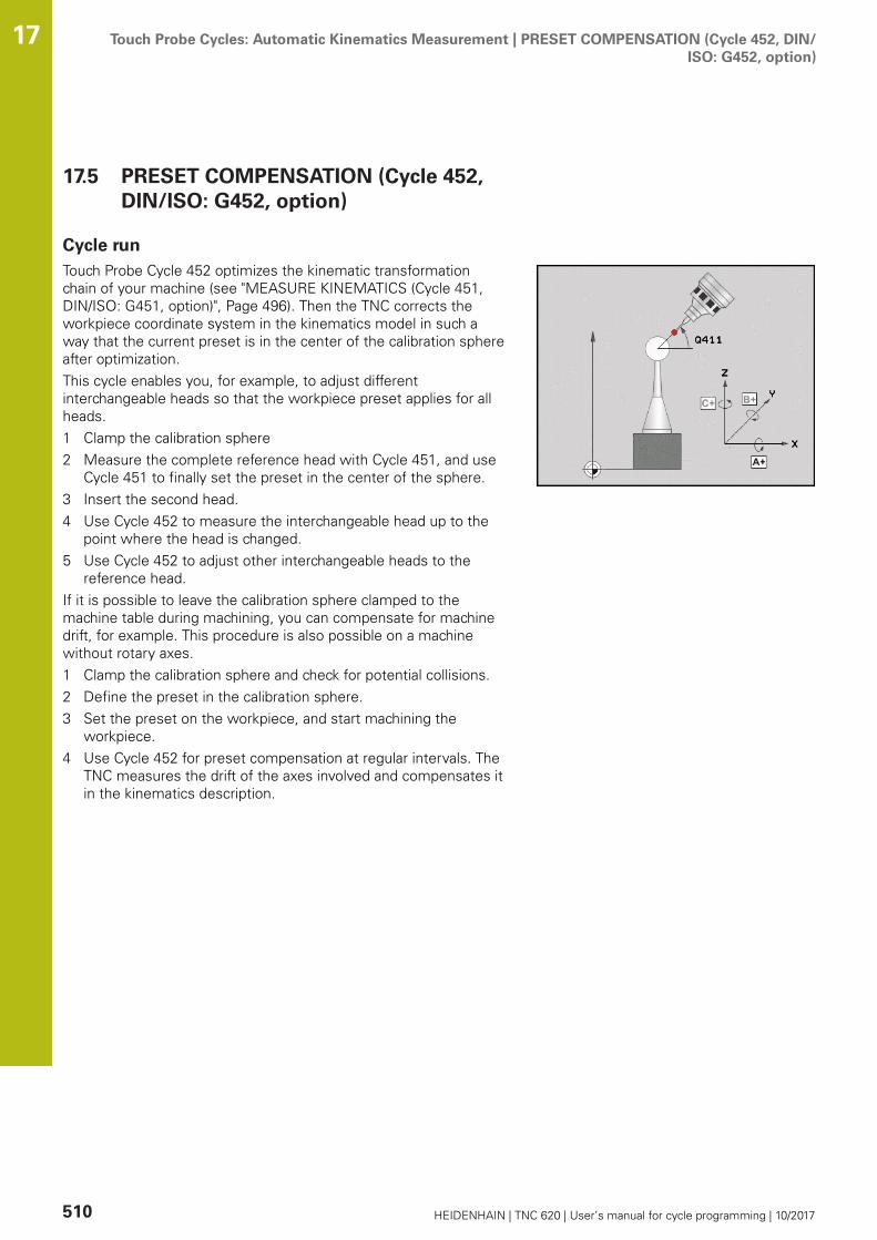
Touch Probe Cycles: Automatic Kinematics Measurement | PRESET COMPENSATION (Cycle 452, DIN/ISO: G452, option)
17
510 HEIDENHAIN | TNC 620 | User’s manual for cycle programming | 10/2017
17.5 PRESET COMPENSATION (Cycle 452,DIN/ISO: G452, option)
Cycle runTouch Probe Cycle 452 optimizes the kinematic transformationchain of your machine (see "MEASURE KINEMATICS (Cycle 451,DIN/ISO: G451, option)", Page 496). Then the TNC corrects theworkpiece coordinate system in the kinematics model in such away that the current preset is in the center of the calibration sphereafter optimization.This cycle enables you, for example, to adjust differentinterchangeable heads so that the workpiece preset applies for allheads.1 Clamp the calibration sphere2 Measure the complete reference head with Cycle 451, and use
Cycle 451 to finally set the preset in the center of the sphere.3 Insert the second head.4 Use Cycle 452 to measure the interchangeable head up to the
point where the head is changed.5 Use Cycle 452 to adjust other interchangeable heads to the
reference head.If it is possible to leave the calibration sphere clamped to themachine table during machining, you can compensate for machinedrift, for example. This procedure is also possible on a machinewithout rotary axes.1 Clamp the calibration sphere and check for potential collisions.2 Define the preset in the calibration sphere.3 Set the preset on the workpiece, and start machining the
workpiece.4 Use Cycle 452 for preset compensation at regular intervals. The
TNC measures the drift of the axes involved and compensates itin the kinematics description.
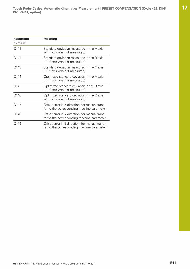
Touch Probe Cycles: Automatic Kinematics Measurement | PRESET COMPENSATION (Cycle 452, DIN/ISO: G452, option)
17
HEIDENHAIN | TNC 620 | User’s manual for cycle programming | 10/2017 511
Parameternumber
Meaning
Q141 Standard deviation measured in the A axis (–1 if axis was not measured)
Q142 Standard deviation measured in the B axis (–1 if axis was not measured)
Q143 Standard deviation measured in the C axis (–1 if axis was not measured)
Q144 Optimized standard deviation in the A axis (–1 if axis was not measured)
Q145 Optimized standard deviation in the B axis (–1 if axis was not measured)
Q146 Optimized standard deviation in the C axis (–1 if axis was not measured)
Q147 Offset error in X direction, for manual trans-fer to the corresponding machine parameter
Q148 Offset error in Y direction, for manual trans-fer to the corresponding machine parameter
Q149 Offset error in Z direction, for manual trans-fer to the corresponding machine parameter
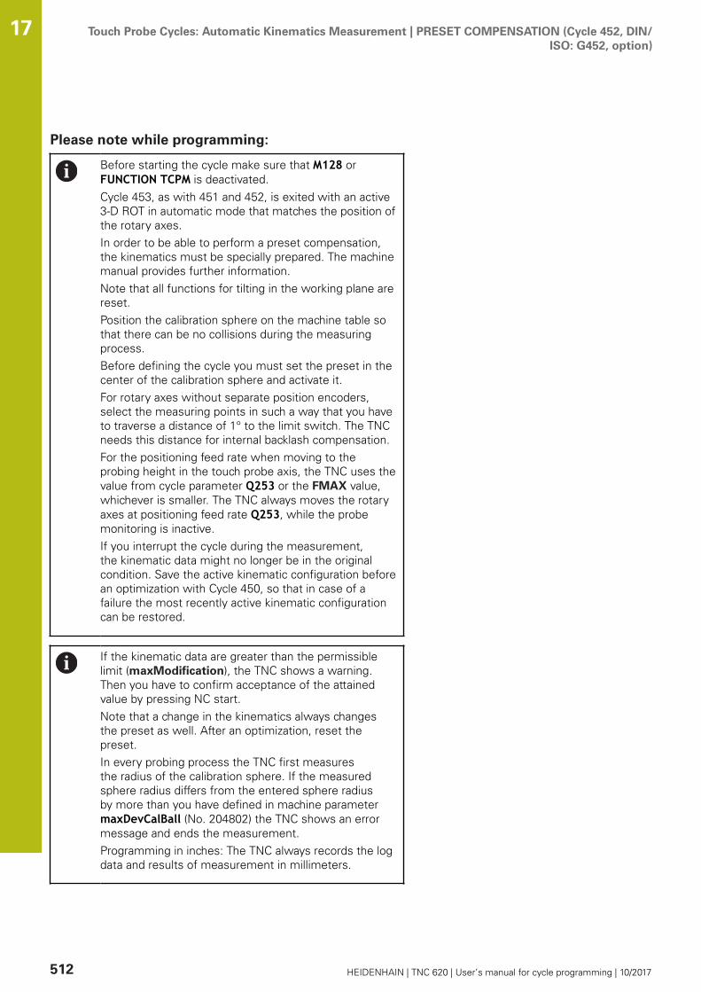
Touch Probe Cycles: Automatic Kinematics Measurement | PRESET COMPENSATION (Cycle 452, DIN/ISO: G452, option)
17
512 HEIDENHAIN | TNC 620 | User’s manual for cycle programming | 10/2017
Please note while programming:
Before starting the cycle make sure that M128 orFUNCTION TCPM is deactivated.Cycle 453, as with 451 and 452, is exited with an active3-D ROT in automatic mode that matches the position ofthe rotary axes.In order to be able to perform a preset compensation,the kinematics must be specially prepared. The machinemanual provides further information.Note that all functions for tilting in the working plane arereset.Position the calibration sphere on the machine table sothat there can be no collisions during the measuringprocess.Before defining the cycle you must set the preset in thecenter of the calibration sphere and activate it.For rotary axes without separate position encoders,select the measuring points in such a way that you haveto traverse a distance of 1° to the limit switch. The TNCneeds this distance for internal backlash compensation.For the positioning feed rate when moving to theprobing height in the touch probe axis, the TNC uses thevalue from cycle parameter Q253 or the FMAX value,whichever is smaller. The TNC always moves the rotaryaxes at positioning feed rate Q253, while the probemonitoring is inactive.If you interrupt the cycle during the measurement,the kinematic data might no longer be in the originalcondition. Save the active kinematic configuration beforean optimization with Cycle 450, so that in case of afailure the most recently active kinematic configurationcan be restored.
If the kinematic data are greater than the permissiblelimit (maxModification), the TNC shows a warning.Then you have to confirm acceptance of the attainedvalue by pressing NC start.Note that a change in the kinematics always changesthe preset as well. After an optimization, reset thepreset.In every probing process the TNC first measuresthe radius of the calibration sphere. If the measuredsphere radius differs from the entered sphere radiusby more than you have defined in machine parametermaxDevCalBall (No. 204802) the TNC shows an errormessage and ends the measurement.Programming in inches: The TNC always records the logdata and results of measurement in millimeters.

Touch Probe Cycles: Automatic Kinematics Measurement | PRESET COMPENSATION (Cycle 452, DIN/ISO: G452, option)
17
HEIDENHAIN | TNC 620 | User’s manual for cycle programming | 10/2017 513
Cycle parametersQ407 Radius of calib. sphere? Enter the exactradius of the calibration sphere used. Input range0.0001 to 99.9999Q320 Set-up clearance? (incremental): Definean additional distance between measuring pointand ball tip. Q320 is added to SET_UP in the touchprobe table. Input range 0 to 99999.9999Q408 Retraction height? (absolute) Input range0.0001 to 99999.99990: Do not move to any retraction height. The TNCmoves to the next measuring position in the axisto be measured. Not allowed for Hirth axes! TheTNC moves to the first measuring position in thesequence A, then B, then C>0: Retraction height in the untilted workpiececoordinate system to which the TNC positionsbefore a rotary axis positioning in the spindleaxis. Also, the TNC moves the touch probe inthe working plane to the datum. The touch probemonitor is not active in this mode. Define thepositioning speed in parameter Q253Q253 Feed rate for pre-positioning? Enter thetraversing speed of the tool in mm/min duringpositioning. Input range 0.0001 to 99999.9999;alternatively FMAX, FAUTO, PREDEFQ380 Ref. angle in ref. axis? (absolute): Enterthe reference angle (basic rotation) for measuringthe measuring points in the active workpiececoordinate system. Defining a reference angle canconsiderably enlarge the measuring range of anaxis. Input range 0 to 360.0000Q411 Starting angle in A axis? (absolute): Startingangle in the A axis at which the first measurementis to be made. Input range -359.999 to 359.999Q412 End angle in A axis? (absolute): End angle inthe A axis at which the last measurement is to bemade. Input range -359.999 to 359.999Q413 Angle of incidence in A axis?: Angle ofincidence in the A axis at which the other rotaryaxes are to be measured. Input range -359.999 to359.999Q414 No. of meas. points in A (0...12)?: Numberof probe measurements with which the TNC is tomeasure the A axis. If the input value = 0, the TNCdoes not measure the respective axis. Input range0 to 12
Calibration program
4 TOOL CALL “TCH PROBE“ Z
5 TCH PROBE 450 SAVE KINEMATICS
Q410=0 ;MODE
Q409=5 ;MEMORY DESIGNATION
6 TCH PROBE 452 PRESETCOMPENSATION
Q407=12.5 ;SPHERE RADIUS
Q320=0 ;SET-UP CLEARANCE
Q408=0 ;RETR. HEIGHT
Q253=750 ;F PRE-POSITIONING
Q380=0 ;REFERENCE ANGLE
Q411=-90 ;START ANGLE A AXIS
Q412=+90 ;END ANGLE A AXIS
Q413=0 ;INCID. ANGLE A AXIS
Q414=0 ;MEAS. POINTS A AXIS
Q415=-90 ;START ANGLE B AXIS
Q416=+90 ;END ANGLE B AXIS
Q417=0 ;INCID. ANGLE B AXIS
Q418=2 ;MEAS. POINTS B AXIS
Q419=-90 ;START ANGLE C AXIS
Q420=+90 ;END ANGLE C AXIS
Q421=0 ;INCID. ANGLE C AXIS
Q422=2 ;MEAS. POINTS C AXIS
Q423=4 ;NO. OF PROBE POINTS
Q432=0 ;BACKLASH, ANG. RANGE

Touch Probe Cycles: Automatic Kinematics Measurement | PRESET COMPENSATION (Cycle 452, DIN/ISO: G452, option)
17
514 HEIDENHAIN | TNC 620 | User’s manual for cycle programming | 10/2017
Q415 Starting angle in B axis? (absolute): Startingangle in the B axis at which the first measurementis to be made. Input range -359.999 to 359.999Q416 End angle in B axis? (absolute): End angle inthe B axis at which the last measurement is to bemade. Input range -359.999 to 359.999Q417 Angle of incidence in B axis?: Angle ofincidence in the B axis at which the other rotaryaxes are to be measured. Input range -359.999 to359.999Q418 No. of meas. points in B (0...12)?: Numberof probe measurements with which the TNC is tomeasure the B axis. If the input value = 0, the TNCdoes not measure the respective axis. Input range0 to 12Q419 Starting angle in C axis? (absolute): Startingangle in the C axis at which the first measurementis to be made. Input range -359.999 to 359.999Q420 End angle in C axis? (absolute): End angle inthe C axis at which the last measurement is to bemade. Input range -359.999 to 359.999Q421 Angle of incidence in C axis?: Angle ofincidence in the C axis at which the other rotaryaxes are to be measured. Input range -359.999 to359.999Q422 No. of meas. points in C (0...12)?: Numberof probe measurements with which the TNC isto measure the C axis. Input range 0 to 12 If theinput value = 0, the TNC does not measure therespective axisQ423 Number of probes? Define the number ofprobe measurements with which the TNC is tomeasure the calibration sphere in the plane. Inputrange: 3 bis 8. Less measuring points increasespeed and more measuring points increasemeasurement precision.Q432 Angular range of backlash comp.?: Hereyou define the angle value to be used as traversefor the measurement of the rotary axis backlash.The traversing angle must be significantly largerthan the actual backlash of the rotary axes. Ifinput value = 0, the TNC does not measure thebacklash. Input range -3.0000 to +3.0000

Touch Probe Cycles: Automatic Kinematics Measurement | PRESET COMPENSATION (Cycle 452, DIN/ISO: G452, option)
17
HEIDENHAIN | TNC 620 | User’s manual for cycle programming | 10/2017 515
Adjustment of interchangeable headsThe goal of this procedure is for the workpiece preset to remainunchanged after changing rotary axes (head exchange).In the following example, a fork head is adjusted to the A and C axes.The A axis is changed, whereas the C axis continues being a part ofthe basic configuration.
Insert the interchangeable head that will be used as a referencehead.Clamp the calibration sphereInsert the touch probeUse Cycle 451 to measure the complete kinematics, including thereference head.Set the preset (using Q431 = 2 or 3 in Cycle 451) after measuringthe reference head
Measuring a reference head
1 TOOL CALL “TCH PROBE“ Z
2 TCH PROBE 451 MEASURE KINEMATICS
Q406=1 ;MODE
Q407=12.5 ;SPHERE RADIUS
Q320=0 ;SET-UP CLEARANCE
Q408=0 ;RETR. HEIGHT
Q253=2000 ;F PRE-POSITIONING
Q380=+45 ;REFERENCE ANGLE
Q411=-90 ;START ANGLE A AXIS
Q412=+90 ;END ANGLE A AXIS
Q413=45 ;INCID. ANGLE A AXIS
Q414=4 ;MEAS. POINTS A AXIS
Q415=-90 ;START ANGLE B AXIS
Q416=+90 ;END ANGLE B AXIS
Q417=0 ;INCID. ANGLE B AXIS
Q418=2 ;MEAS. POINTS B AXIS
Q419=+90 ;START ANGLE C AXIS
Q420=+270 ;END ANGLE C AXIS
Q421=0 ;INCID. ANGLE C AXIS
Q422=3 ;MEAS. POINTS C AXIS
Q423=4 ;NO. OF PROBE POINTS
Q431=3 ;PRESET
Q432=0 ;BACKLASH, ANG. RANGE

Touch Probe Cycles: Automatic Kinematics Measurement | PRESET COMPENSATION (Cycle 452, DIN/ISO: G452, option)
17
516 HEIDENHAIN | TNC 620 | User’s manual for cycle programming | 10/2017
Insert the second interchangeable headInsert the touch probeMeasure the interchangeable head with Cycle 452Measure only the axes that have actually been changed (in thisexample: only the A axis; the C axis is hidden with Q422)The preset and the position of the calibration sphere must not bechanged during the complete processAll other interchangeable heads can be adjusted in the same way
The head change function can vary depending on theindividual machine tool. Refer to your machine manual.
Adjusting an interchangeable head
3 TOOL CALL “TCH PROBE“ Z
4 TCH PROBE 452 PRESETCOMPENSATION
Q407=12.5 ;SPHERE RADIUS
Q320=0 ;SET-UP CLEARANCE
Q408=0 ;RETR. HEIGHT
Q253=2000 ;F PRE-POSITIONING
Q380=+45 ;REFERENCE ANGLE
Q411=-90 ;START ANGLE A AXIS
Q412=+90 ;END ANGLE A AXIS
Q413=45 ;INCID. ANGLE A AXIS
Q414=4 ;MEAS. POINTS A AXIS
Q415=-90 ;START ANGLE B AXIS
Q416=+90 ;END ANGLE B AXIS
Q417=0 ;INCID. ANGLE B AXIS
Q418=2 ;MEAS. POINTS B AXIS
Q419=+90 ;START ANGLE C AXIS
Q420=+270 ;END ANGLE C AXIS
Q421=0 ;INCID. ANGLE C AXIS
Q422=0 ;MEAS. POINTS C AXIS
Q423=4 ;NO. OF PROBE POINTS
Q432=0 ;BACKLASH, ANG. RANGE
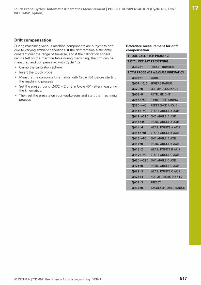
Touch Probe Cycles: Automatic Kinematics Measurement | PRESET COMPENSATION (Cycle 452, DIN/ISO: G452, option)
17
HEIDENHAIN | TNC 620 | User’s manual for cycle programming | 10/2017 517
Drift compensationDuring machining various machine components are subject to driftdue to varying ambient conditions. If the drift remains sufficientlyconstant over the range of traverse, and if the calibration spherecan be left on the machine table during machining, the drift can bemeasured and compensated with Cycle 452.
Clamp the calibration sphereInsert the touch probeMeasure the complete kinematics with Cycle 451 before startingthe machining processSet the preset (using Q432 = 2 or 3 in Cycle 451) after measuringthe kinematics.Then set the presets on your workpieces and start the machiningprocess
Reference measurement for driftcompensation
1 TOOL CALL “TCH PROBE“ Z
2 CYCL DEF 247 PRESETTING
Q339=1 ;PRESET NUMBER
3 TCH PROBE 451 MEASURE KINEMATICS
Q406=1 ;MODE
Q407=12.5 ;SPHERE RADIUS
Q320=0 ;SET-UP CLEARANCE
Q408=0 ;RETR. HEIGHT
Q253=750 ;F PRE-POSITIONING
Q380=+45 ;REFERENCE ANGLE
Q411=+90 ;START ANGLE A AXIS
Q412=+270 ;END ANGLE A AXIS
Q413=45 ;INCID. ANGLE A AXIS
Q414=4 ;MEAS. POINTS A AXIS
Q415=-90 ;START ANGLE B AXIS
Q416=+90 ;END ANGLE B AXIS
Q417=0 ;INCID. ANGLE B AXIS
Q418=2 ;MEAS. POINTS B AXIS
Q419=+90 ;START ANGLE C AXIS
Q420=+270 ;END ANGLE C AXIS
Q421=0 ;INCID. ANGLE C AXIS
Q422=3 ;MEAS. POINTS C AXIS
Q423=4 ;NO. OF PROBE POINTS
Q431=3 ;PRESET
Q432=0 ;BACKLASH, ANG. RANGE

Touch Probe Cycles: Automatic Kinematics Measurement | PRESET COMPENSATION (Cycle 452, DIN/ISO: G452, option)
17
518 HEIDENHAIN | TNC 620 | User’s manual for cycle programming | 10/2017
Measure the drift of the axes at regular intervals.Insert the touch probeActivate the preset in the calibration sphere.Use Cycle 452 to measure the kinematics.The preset and the position of the calibration sphere must not bechanged during the complete process
This procedure can also be performed on machineswithout rotary axes.
Drift compensation
4 TOOL CALL “TCH PROBE“ Z
5 TCH PROBE 452 PRESETCOMPENSATION
Q407=12.5 ;SPHERE RADIUS
Q320=0 ;SET-UP CLEARANCE
Q408=0 ;RETR. HEIGHT
Q253=99999;F PRE-POSITIONING
Q380=+45 ;REFERENCE ANGLE
Q411=-90 ;START ANGLE A AXIS
Q412=+90 ;END ANGLE A AXIS
Q413=45 ;INCID. ANGLE A AXIS
Q414=4 ;MEAS. POINTS A AXIS
Q415=-90 ;START ANGLE B AXIS
Q416=+90 ;END ANGLE B AXIS
Q417=0 ;INCID. ANGLE B AXIS
Q418=2 ;MEAS. POINTS B AXIS
Q419=+90 ;START ANGLE C AXIS
Q420=+270 ;END ANGLE C AXIS
Q421=0 ;INCID. ANGLE C AXIS
Q422=3 ;MEAS. POINTS C AXIS
Q423=3 ;NO. OF PROBE POINTS
Q432=0 ;BACKLASH, ANG. RANGE

Touch Probe Cycles: Automatic Kinematics Measurement | PRESET COMPENSATION (Cycle 452, DIN/ISO: G452, option)
17
HEIDENHAIN | TNC 620 | User’s manual for cycle programming | 10/2017 519
Logging functionAfter running Cycle 452, the TNC creates a measuring log(TCHPR452.TXT) containing the following information:
Creation date and time of the logPath of the NC program from which the cycle was runActive kinematic numberEntered calibration sphere radiusFor each measured rotary axis:
Starting angleEnd angleAngle of incidenceNumber of measuring pointsDispersion (standard deviation)Maximum errorAngular errorAveraged backlashAveraged positioning errorMeasuring circle radiusCompensation values in all axes (preset shift)Measurement uncertainty of rotary axesPosition before preset-compensation of the rotary axeschecked (relative to the beginning of the kinematictransformation chain, usually the spindle nose)Position after preset-compensation of the rotary axeschecked (relative to the beginning of the kinematictransformation chain, usually the spindle nose)
Notes on log data
(see "Logging function", Page 509)

18Touch Probe
Cycles: AutomaticTool Measurement

Touch Probe Cycles: Automatic Tool Measurement | Fundamentals 18
522 HEIDENHAIN | TNC 620 | User’s manual for cycle programming | 10/2017
18.1 Fundamentals
Overview
Operating notesWhen running touch probe cycles, Cycle 8 MIRRORIMAGE, Cycle 11 SCALING and Cycle 26 AXIS-SPECIFIC SCALING must not be active.HEIDENHAIN only assumes liability for functionalityof the probing cycles if HEIDENHAIN touch probesare used.
The TNC and the machine tool must be set up by themachine tool builder for use of the TT touch probe.Some cycles and functions may not be provided on yourmachine tool. Refer to your machine manual.The touch probe cycles are available only with the TouchProbe Functions software option (option 17). If youare using a HEIDENHAIN touch probe, this option isavailable automatically.
In conjunction with the TNC's tool measurement cycles, the tooltouch probe enables you to measure tools automatically. Thecompensation values for tool length and radius can be stored inthe central tool file TOOL.T and are accounted for at the end of thetouch probe cycle. The following types of tool measurement areprovided:
Tool measurement while the tool is at standstillTool measurement while the tool is rotatingMeasurement of individual teeth

Touch Probe Cycles: Automatic Tool Measurement | Fundamentals 18
HEIDENHAIN | TNC 620 | User’s manual for cycle programming | 10/2017 523
You can program the cycles for tool measurement in theProgramming mode of operation using the TOUCH PROBE key. Thefollowing cycles are available:
New format Old format Cycle Page
Calibrating the TT, Cycles 30 and 480 528
Calibrating the wireless TT 449, Cycle 484 530
Measuring the tool length, Cycles 31 and 481 532
Measuring the tool radius, Cycles 32 and 482 534
Measuring the tool length and radius, Cycles 33 and483
536
The measuring cycles can be used only when thecentral tool file TOOL.T is active.Before working with the measuring cycles, you mustfirst enter all the required data into the central tool fileand call the tool to be measured with TOOL CALL.
Differences between Cycles 31 to 33 and Cycles 481 to483The features and the operating sequences are absolutely identical.There are only two differences between Cycles 31 to 33 and Cycles481 to 483:
Cycles 481 to 483 are also available in controls for ISOprogramming under G481 to G483.Instead of a selectable parameter for the status of themeasurement, the new cycles use the fixed parameter Q199.
Touch Probe Cycles: Automatic Tool Measurement | Fundamentals 18
524 HEIDENHAIN | TNC 620 | User’s manual for cycle programming | 10/2017
Setting machine parameters
Before you start working with the measuring cycles,check all machine parameters defined in ProbeSettings> CfgTT (No. 122700) and CfgTTRoundStylus (No.114200).Touch probe cycles 480, 481, 482, 483 and 484 can behidden with the machine parameter hideMeasureTT(No. 128901).The TNC uses the feed rate for probing defined in themachine parameter probingFeed (No.122709) whenmeasuring a tool at standstill.
When measuring a rotating tool, the TNC automatically calculatesthe spindle speed and feed rate for probing.The spindle speed is calculated as follows:n = maxPeriphSpeedMeas / (r • 0.0063) where
n: Spindle speed [rpm]maxPeriphSpeedMeas: Maximum permissible cutting speed in
m/minr: Active tool radius in mm
The feed rate for probing is calculated from:v = measuring tolerance • n with
v: Feed rate for probing in mm/minMeasuring tolerance Measuring tolerance [mm], depending
on maxPeriphSpeedMeasn: Shaft speed [rpm]

Touch Probe Cycles: Automatic Tool Measurement | Fundamentals 18
HEIDENHAIN | TNC 620 | User’s manual for cycle programming | 10/2017 525
probingFeedCalc (No. 122710) determines the calculation of theprobing feed rate:probingFeedCalc (No. 122710) = ConstantTolerance:The measuring tolerance remains constant regardless of the toolradius. With very large tools, however, the feed rate for probingis reduced to zero. The smaller you set the maximum permissiblerotational speed (maxPeriphSpeedMeas No. 122712) and thepermissible tolerance (measureTolerance1 No. 122715), thesooner you will encounter this effect.probingFeedCalc (No. 122710) = VariableTolerance:The measuring tolerance is adjusted relative to the size of the toolradius. This ensures a sufficient feed rate for probing even withlarge tool radii. The TNC adjusts the measuring tolerance accordingto the following table:
Tool radius Measuring tolerance
Up to 30 mm measureTolerance1
30 to 60 mm 2 • measureTolerance1
60 to 90 mm 3 • measureTolerance1
90 to 120 mm 4 • measureTolerance1
probingFeedCalc (No. 122710) = ConstantFeed:The feed rate for probing remains constant; the error ofmeasurement, however, rises linearly with the increase in toolradius:Measuring tolerance = r • measureTolerance1/ 5 mm, where
r: Active tool radius in mmmeasureTolerance1: Maximum permissible error of
measurement

Touch Probe Cycles: Automatic Tool Measurement | Fundamentals 18
526 HEIDENHAIN | TNC 620 | User’s manual for cycle programming | 10/2017
Entries in the tool table TOOL.T
Abbr. Inputs Dialog
CUT Number of teeth (20 teeth maximum) Number of teeth?
LTOL Permissible deviation from tool length L for wear detec-tion. If the entered value is exceeded, the TNC locks thetool (status L). Input range: 0 to 0.9999 mm
Wear tolerance: length?
RTOL Permissible deviation from tool radius R for wear detec-tion. If the entered value is exceeded, the TNC locks thetool (status l). Input range: 0 to 0.9999 mm
Wear tolerance: radius?
R2TOL Permissible deviation from tool radius R2 for wear detec-tion. If the entered value is exceeded, the TNC locks thetool (status l). Input range: 0 to 0.9999 mm
Wear tolerance: Radius 2?
DIRECT. Cutting direction of the tool for measuring the tool duringrotation
Cutting direction (M3 = –)?
R_OFFS Tool length measurement: Tool offset between styluscenter and tool center. Default setting: No value entered(offset = tool radius)
Tool offset: radius?
L_OFFS Tool radius measurement: tool offset in addition to offset-ToolAxis between upper surface of stylus and lowersurface of tool. Default: 0
Tool offset: length?
LBREAK Permissible deviation from tool length L for breakagedetection. If the entered value is exceeded, the TNC locksthe tool (status L). Input range: 0 to 0.9999 mm
Breakage tolerance: length?
RBREAK Permissible deviation from tool radius R for breakagedetection. If the entered value is exceeded, the TNC locksthe tool (status l). Input range: 0 to 0.9999 mm
Breakage tolerance: radius?

Touch Probe Cycles: Automatic Tool Measurement | Fundamentals 18
HEIDENHAIN | TNC 620 | User’s manual for cycle programming | 10/2017 527
Input examples for common tool types
Tool type CUT TT:R_OFFS TT:L_OFFS
Drill – (no function) 0 (no offset requiredbecause tool tip is to bemeasured)
End mill with diameter of< 19 mm
4 (4 teeth) 0 (no offset requiredbecause tool diameter issmaller than the contactplate diameter of the TT)
0 (no additional offsetrequired during radiusmeasurement. Offset fromoffsetToolAxis is used)
End mill with diameter of> 19 mm
4 (4 teeth) R (offset required becausetool diameter is larger thanthe contact plate diameterof the TT)
0 (no additional offsetrequired during radiusmeasurement. Offset fromoffsetToolAxis is used)
Radius cutter with adiameter of 10 mm, forexample
4 (4 teeth) 0 (no offset requiredbecause the south pole ofthe ball is to be measured)
5 (always define the toolradius as the offset sothat the diameter is notmeasured in the radius)

Touch Probe Cycles: Automatic Tool Measurement | Calibrating the TT (Cycle 30 or 480, DIN/ISO: G480option 17)
18
528 HEIDENHAIN | TNC 620 | User’s manual for cycle programming | 10/2017
18.2 Calibrating the TT (Cycle 30 or 480, DIN/ISO: G480 option 17)
Cycle runThe TT is calibrated with the measuring cycle TCH PROBE 30or TCH PROBE 480. (see "Differences between Cycles 31 to 33and Cycles 481 to 483", Page 523). The calibration process runsautomatically. The TNC also measures the center misalignment ofthe calibrating tool automatically by rotating the spindle by 180°after the first half of the calibration cycle.The calibrating tool must be a precisely cylindrical part, for examplea cylinder pin. The resulting calibration values are stored in theTNC memory and are accounted for during subsequent toolmeasurement.Calibration process:1 Clamp the calibrating tool. The calibrating tool must be a
precisely cylindrical part, for example a cylinder pin2 Manually position the calibrating tool in the working plane via
the center of the TT3 Position the calibrating tool in the tool axis approx. 15 mm +
safety clearance above the TT4 The TNC first moves along the tool axis. The tool is first moved
to a clearance height of 15 mm + safety clearance5 The calibration process along the tool axis starts6 Calibration then follows in the working plane7 The TNC initially positions the calibrating tool in the working
plane at a value of 11 mm + radius of TT + safety clearance8 Then the TNC moves the tool downwards along the tool axis
and the calibration process starts9 During the probing the TNC performs a square movement
pattern10 The TNC saves the calibration values and considers these during
subsequent tool measurement11 The TNC then retracts the stylus along the tool axis to safety
clearance and moves it to the center of the TT

Touch Probe Cycles: Automatic Tool Measurement | Calibrating the TT (Cycle 30 or 480, DIN/ISO: G480option 17)
18
HEIDENHAIN | TNC 620 | User’s manual for cycle programming | 10/2017 529
Please note while programming:
The functioning of the calibration cycle is dependent onmachine parameter CfgTTRoundStylus (No. 114200).Refer to your machine manual.The functioning of the cycle is dependent on machineparameter probingCapability (No. 122723). (Thisparameter permits e.g. tool length measurement witha stationary spindle to be enabled and tool radius- andindividual tooth measurement to be simultaneouslydisabled.) Refer to your machine manual.Before calibrating the touch probe, you must enter theexact length and radius of the calibrating tool into thetool table TOOL.T.The position of the TT within the machine workingspace must be defined by setting the machineparameters centerPos (No. 114201) > [0] to [2].If you change the setting of any of the machineparameters centerPos (No. 114201) > [0] to [2], youmust recalibrate.
Cycle parametersQ260 Clearance height?: Enter the position in thespindle axis at which there is no danger of collisionwith the workpiece or fixtures. The clearanceheight is referenced to the active workpiecepreset. If you enter such a small clearance heightthat the tool tip would lie below the level of theprobe contact, the TNC automatically positionsthe tool above the level of the probe contact(safety zone from safetyDistToolAx). Input range-99999.9999 to 99999.9999
NC blocks in old format
6 TOOL CALL 1 Z
7 TCH PROBE 30.0 CALIBRATE TT
8 TCH PROBE 30.1 HEIGHT: +90
NC blocks in new format
6 TOOL CALL 1 Z
7 TCH PROBE 480 CALIBRATE TT
Q260=+100 ;CLEARANCE HEIGHT
Touch Probe Cycles: Automatic Tool Measurement | Calibrating the wireless TT 449 (Cycle 484, DIN/ISO: G484, Option 17)
18
530 HEIDENHAIN | TNC 620 | User’s manual for cycle programming | 10/2017
18.3 Calibrating the wireless TT 449 (Cycle484, DIN/ISO: G484, Option 17)
FundamentalsWith Cycle 484, you can calibrate your tool touch probe, e.g thewireless infrared TT 449 tool touch probe. The calibration processis either fully automatic or semi-automatic, depending on theparameter setting.
Semi-automatic—stop before running: A dialog asks you tomanually move the tool over the TTFully automatic—no stop before running: Before using Cycle484 you must move the tool over the TT
Cycle runTo calibrate the tool touch probe, program the measuring cycle TCHPROBE 484. In the input parameter Q536, you can specify whetheryou want to run the cycle semi-automatically or fully automatically.
Semi-automatic—stop before running
Insert the calibrating toolDefine and start the calibration cycleThe TNC interrupts the calibration cycleThe TNC opens a dialog in a new windowThe dialog asks you to manually position the calibrating toolabove the center of the touch probe. Ensure that the calibratingtool is located above the measuring surface of the probe contact
Fully automatic—no stop before running
Insert the calibrating toolPosition the calibrating tool above the center of the touch probe.Ensure that the calibrating tool is located above the measuringsurface of the probe contactDefine and start the calibration cycleThe calibration cycle is executed without stopping. Thecalibration process starts from the current position of the tool.
Calibrating tool:
The calibrating tool must be a precisely cylindrical part, for examplea cylinder pin. Enter the exact length and radius of the calibratingtool into the tool table TOOL.T. After the calibration, the TNCstores the calibration values and takes them into account duringsubsequent tool measurements. The calibrating tool should havea diameter of more than 15 mm and protrude approx. 50 mm fromthe chuck.

Touch Probe Cycles: Automatic Tool Measurement | Calibrating the wireless TT 449 (Cycle 484, DIN/ISO: G484, Option 17)
18
HEIDENHAIN | TNC 620 | User’s manual for cycle programming | 10/2017 531
Please note while programming:
NOTICEDanger of collision!
To avoid collisions the tool must be pre-positioned before callingthe cycle with Q536=1! In the calibration process, the TNC alsomeasures the center misalignment of the calibrating tool byrotating the spindle by 180° after the first half of the calibrationcycle.
Specify whether to stop before cycle start or run the cycleautomatically without stopping.
The functioning of the cycle is dependent on machineparameter probingCapability (No. 122723). (Thisparameter permits e.g. tool length measurement witha stationary spindle to be enabled and tool radius- andindividual tooth measurement to be simultaneouslydisabled.) Refer to your machine manual.The calibrating tool should have a diameter of more than15 mm and protrude approx. 50 mm from the chuck.When using a cylinder pin of these dimensions, theresulting deformation will only be 0.1 µm per 1 N ofprobing force. The use of a calibrating tool of too smalla diameter and/or protruding too far from the chuck maycause significant inaccuracies.Before calibrating the touch probe, you must enter theexact length and radius of the calibrating tool into thetool table TOOL.T.The TT needs to be recalibrated if you change itsposition on the table.
Cycle parameters
Q536 Stop before running (0=Stop)?: Specify whether to stopbefore cycle start or run the cycle automatically without stopping:0: Stop before running. A dialog asks you to manually positionthe tool above the tool touch probe. After moving the tool to theapproximate position above the tool touch probe, press NC start tocontinue the calibration process or press the CANCEL soft key tocancel the calibration process1: No stop before running. The TNC starts the calibration processfrom the current position. Before running Cycle 484, you mustposition the tool above the tool touch probe.
NC blocks
6 TOOL CALL 1 Z
7 TCH PROBE 484 CALIBRATE TT
Q536=+0 ;STOP BEFORE RUNNING
Touch Probe Cycles: Automatic Tool Measurement | Measuring tool length (Cycle 31 or 481, DIN/ISO: G481,Option 17)
18
532 HEIDENHAIN | TNC 620 | User’s manual for cycle programming | 10/2017
18.4 Measuring tool length (Cycle 31 or 481,DIN/ISO: G481, Option 17)
Cycle runTo measure the tool length, program the measuring cycle TCHPROBE 31 or TCH PROBE 481 (see "Differences between Cycles31 to 33 and Cycles 481 to 483"). Via input parameters you canmeasure the length of a tool by three methods:
If the tool diameter is larger than the diameter of the measuringsurface of the TT, you measure the tool while it is rotating.If the tool diameter is smaller than the diameter of themeasuring surface of the TT, or if you are measuring the lengthof a drill or spherical cutter, you measure the tool while it is atstandstill.If the tool diameter is larger than the diameter of the measuringsurface of the TT, you measure the individual teeth of the toolwhile it is at standstill.
Cycle for measuring a tool during rotation
The control determines the longest tooth of a rotating tool bypositioning the tool to be measured at an offset to the center of thetouch probe and then moving it toward the measuring surface ofthe TT until it contacts the surface. The offset is programmed in thetool table under Tool offset: Radius (TT: R_OFFS).
Cycle for measuring a tool during standstill (e.g. for drills)
The control positions the tool to be measured over the center ofthe measuring surface. It then moves the non-rotating tool towardthe measuring surface of the TT until contact is made. To activatethis function, enter zero for the tool offset: Radius (TT: R_OFFS) inthe tool table.
Cycle for measuring individual teeth
The TNC pre-positions the tool to be measured to a position atthe side of the touch probe head. The distance from the tip ofthe tool to the upper edge of the touch probe head is definedin offsetToolAxis. You can enter an additional offset with tooloffset: Length (TT: L_OFFS) in the tool table. The TNC probesthe tool radially during rotation to determine the starting angle formeasuring the individual teeth. It then measures the length of eachtooth by changing the corresponding angle of spindle orientation.To activate this function, program TCH PROBE 31 = 1 for CUTTERMEASUREMENT.

Touch Probe Cycles: Automatic Tool Measurement | Measuring tool length (Cycle 31 or 481, DIN/ISO: G481,Option 17)
18
HEIDENHAIN | TNC 620 | User’s manual for cycle programming | 10/2017 533
Please note while programming:
Before measuring a tool for the first time, enter thefollowing data on the tool into the tool table TOOL.T: theapproximate radius, the approximate length, the numberof teeth, and the cutting direction.You can run an individual tooth measurement of toolswith up to 20 teeth.
Cycle parametersTool measurement mode (0-2)?: Specify whetherand how the determined data will be entered inthe tool table 0: The measured tool length is written tocolumn L of the tool table TOOL.T, and the toolcompensation is set to DL=0. If there is already avalue stored in TOOL.T, it will be overwritten.1: The measured tool length is compared to thetool length L from TOOL.T. It then calculates thedeviation from the stored value and enters it intoTOOL.T as the delta value DL. The deviation canalso be used for parameter Q115. If the deltavalue is greater than the permissible tool lengthtolerance for wear or break detection, the TNC willlock the tool (status L in TOOL.T)2: The measured tool length is compared to thetool length L from TOOL.T. The TNC calculates thedeviation from the stored value and enters it inQ parameter Q115. Nothing is entered under L orDL in the tool table.Parameter number for result?: Parameternumber in which the TNC saves the status of themeasurement result:0.0: Tool is within tolerance1.0: Tool is worn (LTOL exceeded)2.0: Tool is broken (LBREAK exceeded). If youdo not wish to use the result of measurementwithin the program, answer the dialog prompt withNO ENTClearance height?: Enter the position in thespindle axis at which there is no danger of collisionwith the workpiece or fixtures. The clearanceheight is referenced to the active workpiecepreset. If you enter such a small clearance heightthat the tool tip would lie below the level of theprobe contact, the TNC automatically positionsthe tool above the level of the probe contact(safety zone from safetyDistStylus). Input range-99999.9999 to 99999.9999Probe the teeth? 0=no/1=yes: Choose whetherthe control is to measure the individual teeth(maximum of 20 teeth)
Measuring a rotating tool for the firsttime; old format
6 TOOL CALL 12 Z
7 TCH PROBE 31.0 CAL. TOOL LENGTH
8 TCH PROBE 31.1 CHECK: 0
9 TCH PROBE 31.2 HEIGHT: +120
10 TCH PROBE 31.3 PROBING THETEETH: 0
Inspecting a tool and measuring theindividual teeth and saving the statusin Q5; old format
6 TOOL CALL 12 Z
7 TCH PROBE 31.0 CAL. TOOL LENGTH
8 TCH PROBE 31.1 CHECK: 1 q5
9 TCH PROBE 31.2 HEIGHT: +120
10 TCH PROBE 31.3 PROBING THETEETH: 1
NC blocks in new format
6 TOOL CALL 12 Z
7 TCH PROBE 481 CAL. TOOL LENGTH
Q340=1 ;CHECK
Q260=+100 ;CLEARANCE HEIGHT
Q341=1 ;PROBING THE TEETH
Touch Probe Cycles: Automatic Tool Measurement | Measuring tool radius (Cycle 32 or 482, DIN/ISO: G482,Option 17)
18
534 HEIDENHAIN | TNC 620 | User’s manual for cycle programming | 10/2017
18.5 Measuring tool radius (Cycle 32 or 482,DIN/ISO: G482, Option 17)
Cycle runTo measure the tool radius, program the measuring cycle TCHPROBE 32 or TCH PROBE 482 (see "Differences between Cycles31 to 33 and Cycles 481 to 483", Page 523). Select via inputparameters by which of two methods the radius of a tool is to bemeasured:
Measuring the tool while it is rotatingMeasuring the tool while it is rotating and subsequentlymeasuring the individual teeth.
The TNC pre-positions the tool to be measured to a position atthe side of the touch probe head. The distance from the tip of themilling tool to the upper edge of the touch probe head is defined inoffsetToolAxis. The TNC probes the tool radially while it is rotating.If you have programmed a subsequent measurement of individualteeth, the control measures the radius of each tooth with the aid oforiented spindle stops.
Please note while programming:
Before measuring a tool for the first time, enter thefollowing data on the tool into the tool table TOOL.T: theapproximate radius, the approximate length, the numberof teeth, and the cutting direction.The functioning of the cycle is dependent on machineparameter probingCapability (No. 122723). (Thisparameter permits e.g. tool length measurement witha stationary spindle to be enabled and tool radius- andindividual tooth measurement to be simultaneouslydisabled.) Refer to your machine manual.Cylindrical tools with diamond surfaces can bemeasured with stationary spindle. To do so, define inthe tool table the number of teeth CUT as 0 and adjustmachine parameter CfgTT (No. 122700) Refer to yourmachine manual.

Touch Probe Cycles: Automatic Tool Measurement | Measuring tool radius (Cycle 32 or 482, DIN/ISO: G482,Option 17)
18
HEIDENHAIN | TNC 620 | User’s manual for cycle programming | 10/2017 535
Cycle parametersTool measurement mode (0-2)?: Specify whetherand how the determined data will be entered inthe tool table 0: The measured tool radius is written tocolumn R of the tool table TOOL.T, and the toolcompensation is set to DR=0. If there is already avalue stored in TOOL.T, it will be overwritten.1: The measured tool radius is compared to thetool radius R from TOOL.T. It then calculates thedeviation from the stored value and enters it intoTOOL.T as the delta value DR. The deviation canalso be used for Q parameter Q116. If the deltavalue is greater than the permissible tool radiustolerance for wear or break detection, the TNC willlock the tool (status L in TOOL.T)2: The measured tool radius is compared to thetool radius R from TOOL.T. The TNC calculates thedeviation from the stored value and enters it inQ parameter Q116. Nothing is entered under R orDR in the tool table.Parameter number for result?: Parameternumber in which the TNC saves the status of themeasurement result:0.0: Tool is within tolerance1.0: Tool is worn (RTOL exceeded)2.0: Tool is broken (RBREAK exceeded). If youdo not wish to use the result of measurementwithin the program, answer the dialog prompt withNO ENTClearance height?: Enter the position in thespindle axis at which there is no danger of collisionwith the workpiece or fixtures. The clearanceheight is referenced to the active workpiecepreset. If you enter such a small clearance heightthat the tool tip would lie below the level of theprobe contact, the TNC automatically positionsthe tool above the level of the probe contact(safety zone from safetyDistStylus). Input range-99999.9999 to 99999.9999Probe the teeth? 0=no/1=yes: Choose whetherthe control is to measure the individual teeth(maximum of 20 teeth)
Measuring a rotating tool for the firsttime; old format
6 TOOL CALL 12 Z
7 TCH PROBE 32.0 CAL. TOOL RADIUS
8 TCH PROBE 32.1 CHECK: 0
9 TCH PROBE 32.2 HEIGHT: +120
10 TCH PROBE 32.3 PROBING THETEETH: 0
Inspecting a tool and measuring theindividual teeth and saving the statusin Q5; old format
6 TOOL CALL 12 Z
7 TCH PROBE 32.0 CAL. TOOL RADIUS
8 TCH PROBE 32.1 CHECK: 1 q5
9 TCH PROBE 32.2 HEIGHT: +120
10 TCH PROBE 32.3 PROBING THETEETH: 1
NC blocks in new format
6 TOOL CALL 12 Z
7 TCH PROBE 482 CAL. TOOL RADIUS
Q340=1 ;CHECK
Q260=+100 ;CLEARANCE HEIGHT
Q341=1 ;PROBING THE TEETH

Touch Probe Cycles: Automatic Tool Measurement | Measuring tool length and radius (Cycle 33 or 483, DIN/ISO: G483, Option 17)
18
536 HEIDENHAIN | TNC 620 | User’s manual for cycle programming | 10/2017
18.6 Measuring tool length and radius (Cycle33 or 483, DIN/ISO: G483, Option 17)
Cycle runTo measure both the length and radius of a tool, programthe measuring cycle TCH PROBE 33 or TCH PROBE 483(see "Differences between Cycles 31 to 33 and Cycles 481 to483", Page 523). This cycle is particularly suitable for the firstmeasurement of tools, as it saves time when compared withindividual measurement of length and radius. Via input parametersyou can select the desired type of measurement:
Measuring the tool while it is rotatingMeasuring the tool while it is rotating and subsequentlymeasuring the individual teeth.
The TNC measures the tool in a fixed programmed sequence. Firstit measures the tool radius, then the tool length. The sequence ofmeasurement is the same as for Cycles 31 and 32 as well as .
Please note while programming:
Before measuring a tool for the first time, enter thefollowing data on the tool into the tool table TOOL.T: theapproximate radius, the approximate length, the numberof teeth, and the cutting direction.The functioning of the cycle is dependent on machineparameter probingCapability (No. 122723). (Thisparameter permits e.g. tool length measurement witha stationary spindle to be enabled and tool radius- andindividual tooth measurement to be simultaneouslydisabled.) Refer to your machine manual.Cylindrical tools with diamond surfaces can bemeasured with stationary spindle. To do so, define inthe tool table the number of teeth CUT as 0 and adjustmachine parameter CfgTT (No. 122700) Refer to yourmachine manual.

Touch Probe Cycles: Automatic Tool Measurement | Measuring tool length and radius (Cycle 33 or 483, DIN/ISO: G483, Option 17)
18
HEIDENHAIN | TNC 620 | User’s manual for cycle programming | 10/2017 537
Cycle parametersTool measurement mode (0-2)?: Specify whetherand how the determined data will be entered inthe tool table 0: The measured tool length and measured toolradius are written to columns L and R of the tooltable TOOL.T, and the tool compensation is set toDL=0 and DR=0. If there is already a value storedin TOOL.T, it will be overwritten.1: The measured tool length and measured toolradius are compared to the tool length L and toolradius R from TOOL.T. The TNC calculates thedeviation from the stored value and enters theminto TOOL.T as the delta values DL and DR. Thedeviation is also available in Q parameters Q115and Q116. If the delta value is greater than thepermissible tool length or radius tolerance forwear or break detection, the TNC will lock the tool(status L in TOOL.T)2: The measured tool length and the measuredtool radius are compared to the tool length L andtool radius R from TOOL.T. The TNC calculates thedeviation from the stored value and enters them inQ parameters Q115 and Q116. Nothing is enteredunder L, R, DL, or DR in the tool table.Parameter number for result?: Parameternumber in which the TNC saves the status of themeasurement result:0.0: Tool is within tolerance1.0: Tool is worn (LTOL and/or RTOL exceeded)2.0: Tool is broken (LBREAK and/or RBREAKexceeded) If you do not wish to use the result ofmeasurement within the program, answer thedialog prompt with NO ENTClearance height?: Enter the position in thespindle axis at which there is no danger of collisionwith the workpiece or fixtures. The clearanceheight is referenced to the active workpiecepreset. If you enter such a small clearance heightthat the tool tip would lie below the level of theprobe contact, the TNC automatically positionsthe tool above the level of the probe contact(safety zone from safetyDistStylus). Input range-99999.9999 to 99999.9999Probe the teeth? 0=no/1=yes: Choose whetherthe control is to measure the individual teeth(maximum of 20 teeth)
Measuring a rotating tool for the firsttime; old format
6 TOOL CALL 12 Z
7 TCH PROBE 33.0 MEASURE TOOL
8 TCH PROBE 33.1 CHECK: 0
9 TCH PROBE 33.2 HEIGHT: +120
10 TCH PROBE 33.3 PROBING THETEETH: 0
Inspecting a tool and measuring theindividual teeth and saving the statusin Q5; old format
6 TOOL CALL 12 Z
7 TCH PROBE 33.0 MEASURE TOOL
8 TCH PROBE 33.1 CHECK: 1 q5
9 TCH PROBE 33.2 HEIGHT: +120
10 TCH PROBE 33.3 PROBING THETEETH: 1
NC blocks in new format
6 TOOL CALL 12 Z
7 TCH PROBE 483 MEASURE TOOL
Q340=1 ;CHECK
Q260=+100 ;CLEARANCE HEIGHT
Q341=1 ;PROBING THE TEETH


19Tables of Cycles
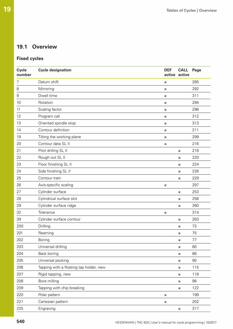
Tables of Cycles | Overview 19
540 HEIDENHAIN | TNC 620 | User’s manual for cycle programming | 10/2017
19.1 Overview
Fixed cycles
Cyclenumber
Cycle designation DEFactive
CALLactive
Page
7 Datum shift ■ 285
8 Mirroring ■ 292
9 Dwell time ■ 311
10 Rotation ■ 294
11 Scaling factor ■ 296
12 Program call ■ 312
13 Oriented spindle stop ■ 313
14 Contour definition ■ 211
19 Tilting the working plane ■ 299
20 Contour data SL II ■ 216
21 Pilot drilling SL II ■ 218
22 Rough out SL II ■ 220
23 Floor finishing SL II ■ 224
24 Side finishing SL II ■ 226
25 Contour train ■ 229
26 Axis-specific scaling ■ 297
27 Cylinder surface ■ 253
28 Cylindrical surface slot ■ 256
29 Cylinder surface ridge ■ 260
32 Tolerance ■ 314
39 Cylinder surface contour ■ 263
200 Drilling ■ 73
201 Reaming ■ 75
202 Boring ■ 77
203 Universal drilling ■ 80
204 Back boring ■ 86
205 Universal pecking ■ 90
206 Tapping with a floating tap holder, new ■ 115
207 Rigid tapping, new ■ 118
208 Bore milling ■ 98
209 Tapping with chip breaking ■ 122
220 Polar pattern ■ 199
221 Cartesian pattern ■ 202
225 Engraving ■ 317

Tables of Cycles | Overview 19
HEIDENHAIN | TNC 620 | User’s manual for cycle programming | 10/2017 541
Cyclenumber
Cycle designation DEFactive
CALLactive
Page
232 Face milling ■ 323
233 Face milling (selectable milling direction, consider the side walls) ■ 186
239 Ascertain the load ■ 328
240 Centering ■ 71
241 Single-lip deep-hole drilling ■ 101
247 Presetting ■ 291
251 Rectangular pocket (complete machining) ■ 151
252 Circular pocket (complete machining) ■ 156
253 Slot milling ■ 162
254 Circular slot ■ 166
256 Rectangular stud (complete machining) ■ 172
257 Circular stud (complete machining) ■ 177
258 Polygon stud ■ 181
262 Thread milling ■ 128
263 Thread milling/countersinking ■ 131
264 Thread drilling/milling ■ 135
265 Helical thread drilling/milling ■ 139
267 Outside thread milling ■ 143
270 Contour train data ■ 238
275 Trochoidal slot ■ 240
276 3-D contour train ■ 233

Tables of Cycles | Overview 19
542 HEIDENHAIN | TNC 620 | User’s manual for cycle programming | 10/2017
Touch probe cycles
Cyclenumber
Cycle designation DEFactive
CALLactive
Page
0 Reference plane ■ 432
1 Polar preset ■ 433
3 Measuring ■ 471
4 Measuring in 3-D ■ 473
444 Probing in 3D ■ "3D PROBING(Cycle 444),(softwareoption 17)"
30 Calibrate the TT ■ 528
31 Measure/Inspect the tool length ■ 532
32 Measure/Inspect the tool radius ■ 534
33 Measure/Inspect the tool length and the tool radius ■ 536
400 Basic rotation using two points ■ 347
401 Basic rotation over two holes ■ 350
402 Basic rotation over two studs ■ 354
403 Compensate misalignment with rotary axis ■ 358
404 Set basic rotation ■ 362
405 Compensate misalignment with the C axis ■ 363
408 Preset at slot center (FCL 3 function) ■ 372
409 Preset at ridge center (FCL 3 function) ■ 376
410 Preset from inside of rectangle ■ 380
411 Preset from outside of rectangle ■ 384
412 Preset from inside of circle (hole) ■ 388
413 Preset from outside of circle (stud) ■ 393
414 Preset from outside of corner ■ 398
415 Preset from inside of corner ■ 403
416 Preset from circle center ■ 408
417 Preset in touch probe axis ■ 412
418 Preset at center between four holes ■ 414
419 Preset in any one axis ■ 418
420 Workpiece—measure angle ■ 434
421 Workpiece—measure hole (center and diameter of hole) ■ 437
422 Workpiece—measure circle from outside (diameter of circular stud) ■ 441
423 Workpiece—measure rectangle from inside ■ 445
424 Workpiece—measure rectangle from outside ■ 448
425 Workpiece—measure inside width (slot) ■ 451
426 Workpiece—measure outside width (ridge) ■ 454
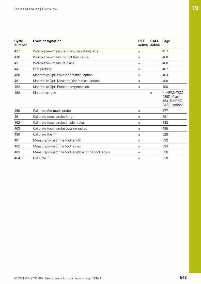
Tables of Cycles | Overview 19
HEIDENHAIN | TNC 620 | User’s manual for cycle programming | 10/2017 543
Cyclenumber
Cycle designation DEFactive
CALLactive
Page
427 Workpiece—measure in any selectable axis ■ 457
430 Workpiece—measure bolt hole circle ■ 460
431 Workpiece—measure plane ■ 460
441 Fast probing ■ 487
450 KinematicsOpt: Save kinematics (option) ■ 493
451 KinematicsOpt: Measure kinematics (option) ■ 496
452 KinematicsOpt: Preset compensation ■ 490
453 Kinematics grid ■ "KINEMATICSGRID (Cycle453, DIN/ISO:G453, option)"
460 Calibrate the touch probe ■ 477
461 Calibrate touch probe length ■ 481
462 Calibrate touch probe inside radius ■ 483
463 Calibrate touch probe outside radius ■ 485
480 Calibrate the TT ■ 528
481 Measure/Inspect the tool length ■ 532
482 Measure/Inspect the tool radius ■ 534
483 Measure/Inspect the tool length and the tool radius ■ 536
484 Calibrate TT ■ 530

Index
544 HEIDENHAIN | TNC 620 | User’s manual for cycle programming | 10/2017
Index
3
3D Touch Probes...................... 334
A
About this manual........................ 4Automatic datum setting.......... 368
At center of 4 holes............. 414Center of a bolt hole circle... 408Center of a circular pocket(hole).................................... 388Center of a circular stud....... 393Center of a rectangularpocket.................................. 380Center of a rectangular stud 384In any axis............................ 418Inside of corner.................... 403In the touch probe axis........ 412Outside of corner................. 398Ridge center........................ 376Slot center........................... 372
Automatic tool measurement... 526Axis-specific scaling................. 297
B
Back boring................................ 86Basic rotation
Measure during programrun........................................ 344
Bolt hole circle......................... 199Bore milling................................ 98Boring......................................... 77
C
Centering................................... 71Circular pocket
Roughing+finishing.............. 156Circular point patterns.............. 199Circular slot
Roughing+finishing.............. 166Circular stud............................. 177Classification of results............ 429Compensating workpiecemisalignment............................ 344
By measuring two points on astraight line.......................... 347Over two circular studs........ 354Over two holes.................... 350Via rotary axis.............. 358, 363
Consideration of basic rotation. 335Contour cycles......................... 208Contour train............ 229, 233, 238Coordinate transformation........ 284Cycle.......................................... 50
Calling.................................... 52
Define.................................... 51Cycles and point tables.............. 67Cylinder surface
Machine contour.......... 253, 263Ridge machining.................. 260Slot machining..................... 256
D
Datum shift.............................. 285In the program..................... 285With datum tables............... 286
Drilling............................ 73, 80, 90Drilling Cycles............................ 70Dwell time................................ 311
E
Engraving................................. 317
F
Face milling.............................. 323FCL function.............................. 10Feature Content Level................ 10Floor finishing........................... 224Fundamentals of ThreadMilling...................................... 126
H
Helical thread drilling/milling..... 139
I
Inside thread milling................. 128
K
Kinematic measurementAccuracy.............................. 501Backlash............................... 503Calibration methods.... 502, 515,517Hirth coupling...................... 499Logging function.. 494, 509, 519Measuring point selection....495, 500Measuring position selection....501Prerequisites........................ 491
Kinematics measurement........ 490Kinematics Measurement
Measure kinematics..... 496, 510Kinematics measurement
Save kinematics................... 493KinematicsOpt.......................... 490
L
Linear point patterns................ 202
M
Machine parameters for 3D touch
probe........................................ 337Machining pattern...................... 58Measure angle......................... 434Measure angle of a plane......... 463Measure any coordinate........... 457Measure bolt hole circle........... 460Measure hole........................... 437Measure hole inside................. 437Measure hole outside.............. 441Measure kinematics................. 496
Preset compensation........... 510Measurement parameters........ 429Measurement results in Qparameters............................... 429Measure rectangular pocket..... 448Measure rectangular stud........ 445Measure the plane angle.......... 463Measure the slot width............ 451Measure the width of aridge................................. 454, 454Measuring slot width............... 451Measuring the width of a ridge 454Mirroring................................... 292
O
Outside thread milling.............. 143
P
Pattern definition........................ 58Peck drilling........................ 90, 101Point patterns........................... 198
Overview............................. 198Point tables................................ 65Polygon stud............................ 181Positioning logic....................... 339Probing feed rate..................... 338Program call............................. 312
Via cycle............................... 312
R
Reaming..................................... 75Recording measurement results....427Rectangular pocket
Roughing+finishing.............. 151Rectangular stud...................... 172Rotation.................................... 294Roughing
\See SL Cycles, Roughing.... 220
S
Scaling...................................... 296Set a basic rotation.................. 362Side finishing............................ 226Single-lip deep-hole drilling....... 101SL Cycles................. 208, 253, 263
Contour cycle....................... 211Contour data........................ 216

HEIDENHAIN | TNC 620 | User’s manual for cycle programming | 10/2017 545
Contour train........ 229, 233, 238Floor finishing...................... 224
SL cyclesFundamentals.............. 208, 280
SL CyclesPilot drilling.......................... 218Roughing.............................. 220Side finishing....................... 226Superimposed contours.... 212,274
SL cycles with complex contourformula..................................... 270SL cycles with simple contourformula..................................... 280Slot milling
Roughing+finishing.............. 162Spindle orientation................... 313
T
TappingWith a floating tap holder..... 115With chip breaking............... 122Without a floating tapholder........................... 118, 122
Thread drilling/milling............... 135Thread milling/countersinking... 131Thread milling inside................ 330Tilting function
Procedure............................ 305Tilting the working plane.. 299, 299
Cycle................................... 299Tolerance monitoring................ 429Tool compensation................... 430Tool measurement........... 522, 526
Calibrate TT.......................... 530Calibrating the TT................. 528Machine parameters............ 524Measuring tool length andradius................................... 536Tool length........................... 532Tool radius............................ 534
Tool monitoring........................ 430Touch probe cycles
For automatic mode............. 336Touch probe data...................... 341Touch probe table..................... 340
U
Universal drilling................... 80, 90
W
Workpiece Measurement......... 426

DR. JOHANNES HEIDENHAIN GmbHDr.-Johannes-Heidenhain-Straße 583301 Traunreut, Germany +49 8669 31-0 +49 8669 32-5061E-mail: [email protected]
Technical support +49 8669 32-1000Measuring systems +49 8669 31-3104
E-mail: [email protected] support +49 8669 31-3101
E-mail: [email protected] programming +49 8669 31-3103
E-mail: [email protected] programming +49 8669 31-3102
E-mail: [email protected] programming +49 8669 31-3106
E-mail: [email protected]
www.heidenhain.de
Klartext App
The Klartext on YourMobile Device
Google ApplePlay Store App Store
www.klartext-portal.com
The Information Site forHEIDENHAIN Controls
Original document1096886-24 · Ver04 · SW05 · 10/2017 · H · Printed in Germany *I1096886-24*
Touch probes from HEIDENHAINhelp you reduce non-productive time and improve thedimensional accuracy of the finished workpieces.
Workpiece touch probesTS 220 Signal transmission by cableTS 440, TS 444 Infrared transmissionTS 640, TS 740 Infrared transmission
Workpiece alignmentSetting presetsWorkpiece measurement
Tool touch probesTT 140 Signal transmission by cableTT 449 Infrared transmissionTL Non-contacting laser systems
Tool measurementwear monitoringtool breakage detection