TN463 Temperature design 072616 -...
16
Technical Notes Post-Tensioning Expertise and Design August 26,2016 TN463_Temperature_design TEMPERATURE DESIGN OF POST-TENSIONED FLOORS 1 Bijan Aalami 2 1. TEMPERATURE LOAD 1.1 Daily Changes in Temperature 1.2 Seasonal or Other Long-Term Change in Temperature 2. TEMPERATURE LOAD EFFECTS 3. DESIGN FOR TEMPERATURE EFFECTS 3.1 Temperature Reinforcement 3.2 Cracking and Deflection Check 4. DETAILING 5. DESIGN EXAMPLE 5.1 First slab above the podium construction A. Transverse Direction B. Longitudinal Direction 5.2 Typical level A. Transverse direction B. Longitudinal direction 5.3 Roof Level APPENDIX Temperature Analysis and Design Aid REFERENCES Daily temperature changes, differences in the ambient temperature between when a building is under construction and when it is in service, and differences in ambient temperatures on different levels can all create stresses in a concrete frame building. This Technical Note discusses the effects of temperature change on concrete floor slabs with and without post- tensioning and shows how to design for temperature change using the ACI 318 building code. The Note concludes with a design example for a multi-story building. 1 – TEMPERATURE LOAD Temperature change can result in stresses and deformation in concrete frame buildings. In most cases, the effects of temperature change are within the acceptable range of the building’s in-service response. However there are conditions where the effects of temperature change are large and must be evaluated and accounted for, to mitigate their adverse impact on the building’s performance. 1 Copyright Bijan Aalami 2016; ADAPT Corporation 2 Professor Emeritus, San Francisco State University; Principal, ADAPT Corporation
-
Upload
truongminh -
Category
Documents
-
view
217 -
download
0
Transcript of TN463 Temperature design 072616 -...

Technical Notes
Post-Tensioning Expertise and Design August 26,2016
TN463_Temperature_design
TEMPERATURE DESIGN OF POST-TENSIONED FLOORS1
Bijan Aalami2
1. TEMPERATURE LOAD
1.1 Daily Changes in Temperature 1.2 Seasonal or Other Long-Term Change in Temperature
2. TEMPERATURE LOAD EFFECTS 3. DESIGN FOR TEMPERATURE EFFECTS 3.1 Temperature Reinforcement
3.2 Cracking and Deflection Check 4. DETAILING 5. DESIGN EXAMPLE
5.1 First slab above the podium construction A. Transverse Direction B. Longitudinal Direction
5.2 Typical level A. Transverse direction B. Longitudinal direction
5.3 Roof Level APPENDIX
Temperature Analysis and Design Aid
REFERENCES Daily temperature changes, differences in the ambient temperature between when a building is under construction and when it is in service, and differences in ambient temperatures on different levels can all create stresses in a concrete frame building. This Technical Note discusses the effects of temperature change on concrete floor slabs with and without post-tensioning and shows how to design for temperature change using the ACI 318 building code. The Note concludes with a design example for a multi-story building. 1 – TEMPERATURE LOAD Temperature change can result in stresses and deformation in concrete frame buildings. In most cases, the effects of temperature change are within the acceptable range of the building’s in-service response. However there are conditions where the effects of temperature change are large and must be evaluated and accounted for, to mitigate their adverse impact on the building’s performance. 1 Copyright Bijan Aalami 2016; ADAPT Corporation 2 Professor Emeritus, San Francisco State University; Principal, ADAPT Corporation
Technical Notes
TN463 - 2
1.1 Daily Changes in Temperature Daily ambient temperature changes for exposed roof slabs can lead to temperature gradients through the slab depth. The daily change in temperature subjects the slab to “short term” but repetitive temperature effects. The gradient will depend on the exposure and slab thickness but can exceed 10 oC (50 oF)
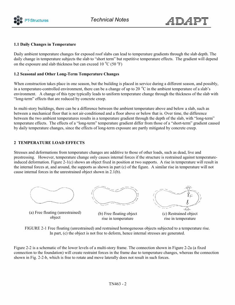
, 1.2 Seasonal and Other Long-Term Temperature Changes When construction takes place in one season, but the building is placed in service during a different season, and possibly, in a temperature-controlled environment, there can be a change of up to 20 oC in the ambient temperature of a slab’s environment. A change of this type typically leads to uniform temperature change through the thickness of the slab with “long-term” effects that are reduced by concrete creep. In multi-story buildings, there can be a difference between the ambient temperature above and below a slab, such as between a mechanical floor that is not air-conditioned and a floor above or below that is. Over time, the difference between the two ambient temperatures results in a temperature gradient through the depth of the slab, with “long-term” temperature effects. The effects of a “long-term” temperature gradient differ from those of a “short-term” gradient caused by daily temperature changes, since the effects of long-term exposure are partly mitigated by concrete creep. 2 TEMPERATURE LOAD EFFECTS Stresses and deformations from temperature changes are additive to those of other loads, such as dead, live and prestressing. However, temperature change only causes internal forces if the structure is restrained against temperature-induced deformation. Figure 2-1(c) shows an object fixed in position at two supports. A rise in temperature will result in the internal forces at, and around, the supports as shown in part (c) of the figure. A similar rise in temperature will not cause internal forces in the unrestrained object shown in 2.1(b).
(a) Free floating (unrestrained)
object
(b) Free floating object
rise in temperature
(c) Restrained object rise in temperature
FIGURE 2-1 Free floating (unrestrained) and restrained homogeneous objects subjected to a temperature rise.
In part, (c) the object is not free to deform, hence internal stresses are generated. Figure 2-2 is a schematic of the lower levels of a multi-story frame. The connection shown in Figure 2-2a (a fixed connection to the foundation) will create restraint forces in the frame due to temperature changes, whereas the connection shown in Fig. 2-2-b, which is free to rotate and move laterally does not result in such forces.

Technical Notes
TN463 - 3
(a) Frame fixed at bottom
(statically indeterminate)
(b) Frame on roller supports
(statically determinate)
FIGURE 2-2 Partial Elevation of Multi-Story Frame.
Because the statically determinate connection to the supports shown in (b) allows free movement of the structure, there are no internal stresses
from temperature change, whereas the restrained (indeterminate connection) in (a) leads to internal stresses.
For building frames, the global constraints are generally the connections to the foundations. The restraint forces decrease rapidly with distance from the foundation. Figure 2-3 illustrates this concept for a multistory frame subjected to a uniform change in temperature. Note that by the second elevated slab, the forces will no longer be significant for design. The distribution shown in Fig. 2-3 assumes that the frame will respond elastically and there is no cracking. In practice, minute cracks are likely to develop at the floor connections to its supports, and along the columns and walls. These cracks relieve the temperature-generated forces so that concrete structures are rarely subjected to the level of internal stresses that are calculated from a non-cracked elastic analysis.
(a) Moments
(b) Axial forces
FIGURE 2-3 Partial elevation of a concrete frame with restrained supports
subject to a uniform change in temperature over the entire frame. The change in temperature results in forces in wall/column supports and floors at or near the supports but these forces decrease rapidly with distance from the supports.
The following temperature change example illustrates the impact of temperature load on post-tensioned members. Note that the coefficients of thermal expansion for concrete and steel are similar, and for design purposes, they can be considered to be the same. The following parameters are used to represent a typical post-tensioned floor slab:
α = 12×10-6 / oC ; coefficient of thermal expansion of both concrete and steel (54×10-6 / oF) ;

Technical Notes
TN463 - 4
f’c = 35 MPa ; 28 day concrete cylinder strength (5,076 psi) ; Ec = 35,000 MPa ; modulus of elasticity of concrete (5,076 ksi) ; Ccr = 2 ; creep coefficient of concrete, for long-term effects of temperature;
'0.33r cf f= ; cracking stress of concrete under uniform tension ( '4r cf f= ); Es = 200,000 MPa ; modulus of elasticity of prestressing steel (29,008 ksi) ;
v Post-tensioned floors are typically designed for 1 MPa (145 psi) precompression for service condition. v The change in ambient temperature over long-term for illustration purposes is assumed 20 oC (68 oF) . v The daily temperature gradient through the depth of an exposed post-tensioned slab, such as roof slab is
assumed 10 oC (50 oF). v Concrete strain to cause 1 MPa stress is ε =1/35,000 = 28.6x10⁻⁶ 28.6 micro strain v Temperature change to cause strain associated with 1 MPa stress in concrete is: T = 28.6x10⁻⁶/12x10-6 = 2.38 oC (4,28 oF)
Using the preceding values and the expression '0.33r cf f= ( '4r cf f= ), for concrete with f’c = 35 MPa (5,076 psi), the cracking stress, fr = 1.95 MPa (283 psi).
61.95 / 35000 56 10c r cf Eε −= = = × ; Thus the concrete strain at the initiation of cracking will be 56 micro-strains The instantaneous drop in temperature that will lead to cracking of restrained concrete is therefore: 6 656 10 12 10 4.67cT ε α − −= = × × = Co (8.41 oF) Long-term drop in temperature to cause through crack of restrained concrete = 2 x 4.67 = 9.33 oC (16.79 oF) Where 2 is the assumed ultimate creep coefficient of concrete Figure 2-5 illustrates the response of a concrete element under different conditions of temperature change, support restraint, and post-tensioning. 3 DESIGN FOR TEMPERATURE EFFECTS 3.1 Temperature Reinforcement The load combination for temperature design is the “sustained” (quasi permanent) condition, to which the temperature effect is added. U = 1.00DL + KlLL + KtT (Exp 3.1-1) Where Kt is the coefficient of temperature effects. For a change in ambient temperature, Kt=0.5. This is based on the assumption that the temperature change takes place over a month or longer, so that the creep response of concrete governs. The ultimate creep factor for concrete is generally taken as 2 – hence the 0.5 factor for Kt. For a temperature gradient taking place on daily basis Kt=1.

Technical Notes
TN463 - 5
(a) Full restraint: temperature drop results in tension. A drop of about 2.38 oC (4.28 oF)results in 1 MPa (145 psi) tension
(b) Full restraint: approximately 5 oC (9 oF) instantaneous or 10 oC (18 oF) long-term temperature drop results in a through crack.
(c) No restraint: temperature change does not cause internal stresses
(d) Restrained at supports; stresses generated in the element depend on the stiffness of the restraint, but will be less than the case of full restraint shown in(b)
(e) Post-tensioned element with no restraint: no stress change in concrete from temperature change. Precompression from prestressing remains unchanged.
(f) Post-tensioned element with full restraint: prestressing does not affect the element response to temperature change. Concrete response will be similar to cases (a) through (d)
FIGURE 2-5 Concrete Element Subjected to Temperature Change
The impact of support restraint and prestressing on a concrete element is illustrated. The coefficients of thermal expansion for concrete and steel are assumed to be the same.
(PTS804;PTS805) The fraction of live load for the sustained (quasi permanent) condition depends on the building code used. ACI 318 leaves it to the judgment of the design engineer. The common practice is to use Kl=0.3 for common residential and commercial buildings. Temperature drop and shrinkage have similar effects on concrete elements. ACI 318-11, §7.12.2 requires the following when members are designed using post-tensioning to control cracking from temperature and shrinkage.
“Tendons shall be proportioned to provide a minimum average compressive stress of 100 psi (0.69 MPa) on gross concrete area using effective prestress, after losses…”
For conventionally reinforced members, ACI 318-11’s recommendation is to provide deformed bars or welded wire mesh of not less than 0.18% of the section’s gross cross-sectional area. For post-tensioned members, the temperature and

Technical Notes
TN463 - 6
shrinkage requirements can be satisfied with a combination of prestressed and non-prestressed reinforcement, as shown in Fig. 3-1 (graphical presentation of ACI 318-11 §7.12.2) .
FIGURE 3-1 Minimum Temperature and Shrinkage
Requirement for Post-Tensioned Members A combination of precompression and non-prestressed
reinforcement can be used to meet the minimum temperature and shrinkage reinforcement required by
ACI 318-14 (§7.12.2) From Fig. 3-1, the following applies when unbonded reinforcement is used:
100/(P/A) + (As/Ac)/0.0018 ≥ 1 (Exp 3-1.2) When bonded post-tensioning is used, the area of the strands can be included in accordance with Exp 3.1-3, provided the tendon layout meets the detailing requirements outlined in Section 4. 100/(P/A) + [(As+Aps)/Ac)]/0.0018 ≥ 1 (Exp 3-1.3) Where;
P/A = average precompression; As = nonprestressed steel cross-sectional area; Ac = concrete cross-sectional area; and Aps = cross-sectional area of bonded prestressing.

Technical Notes
TN463 - 7
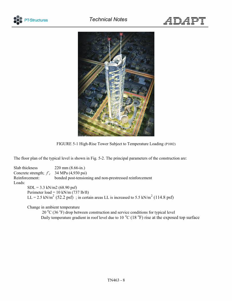
3.2 Cracking and Deflection Check Possible consequences of changes in temperature are extreme fiber cracking and enlargement of existing cracks. Either condition can cause an increase in member deflection. Where deflection of a member is critical, its value under temperature load should be computed and verified for compliance. 4 DETAILING Temperature and shrinkage reinforcement is designed to control crack width. For slab dimensions common in residential and commercial construction ACI 318-113 recommends a maximum spacing of 18 in (450 mm) or 1.5 times the slab thickness. ACI 318-114 also has a maximum spacing for unbonded tendons that are intended for temperature control, but in the author’s opinion, the spacing of unbonded tendons does not relate to the control of cracking from temperature and shrinkage effects – rather, it is the resulting precompression that affects the cracking. This requirement can be waived if necessary to simplify the tendon placement. The European code EC2 recommends a maximum spacing of 450 mm5 between reinforcement intended for shrinkage and temperature control. Where bonded tendons are used, for spacing requirements, each bonded tendon is viewed equivalent to a non-prestressed reinforcement. Hence, the applicable clear spacing between adjacent sheathing of bonded tendons, or a post-tensioned bonded tendon and the next non-prestressed reinforcement is the same as stipulated above. Flor post-tensioned members, temperature reinforcement, where required, is placed on the side of the member with smaller compression. This is generally the side, where tendons are located. 5 DESIGN EXAMPLE The high-rise building shown in Fig. 5-1 extends above the plaza level at the base. The building will be constructed in an environment where there will be a significant change in the ambient temperature between the construction in open air and the completed, air-conditioned building. The change in ambient temperature between construction and the completed building is estimated to be 20 oC (36 oF). In addition, at the roof level, the daily change between the exposed surface and the uppermost floor is expected to result in a temperature gradient of 10 oC (18 oF) through the depth of the roof slab. It is necessary to determine whether the reinforcement specified for the gravity and lateral design of the building is adequate for the temperature load; and if deficient, to determine the reinforcement needed to account for the effects of temperature load.
3 ACI 318-11, Section 7.12.2.2 4 ACI 318-11 Section 7.12.3.4 5 EC2 1992-1-1:2004, Section 9.3.1.1
Technical Notes
TN463 - 8
FIGURE 5-1 High-Rise Tower Subject to Temperature Loading (P1002)
The floor plan of the typical level is shown in Fig. 5-2. The principal parameters of the construction are: Slab thickness 220 mm (8.66-in.) Concrete strength; f’c 34 MPa (4,930 psi) Reinforcement: bonded post-tensioning and non-prestressed reinforcement Loads:
SDL = 3.3 kN/m2 (68.90 psf) Perimeter load = 10 kN/m (737 lb/ft) LL = 2.5 kN/m2 (52.2 psf) ; in certain areas LL is increased to 5.5 kN/m2 (114.8 psf) Change in ambient temperature
20 oC (36 oF) drop between construction and service conditions for typical level Daily temperature gradient in roof level due to 10 oC (18 oF) rise at the exposed top surface
Technical Notes
TN463 - 9
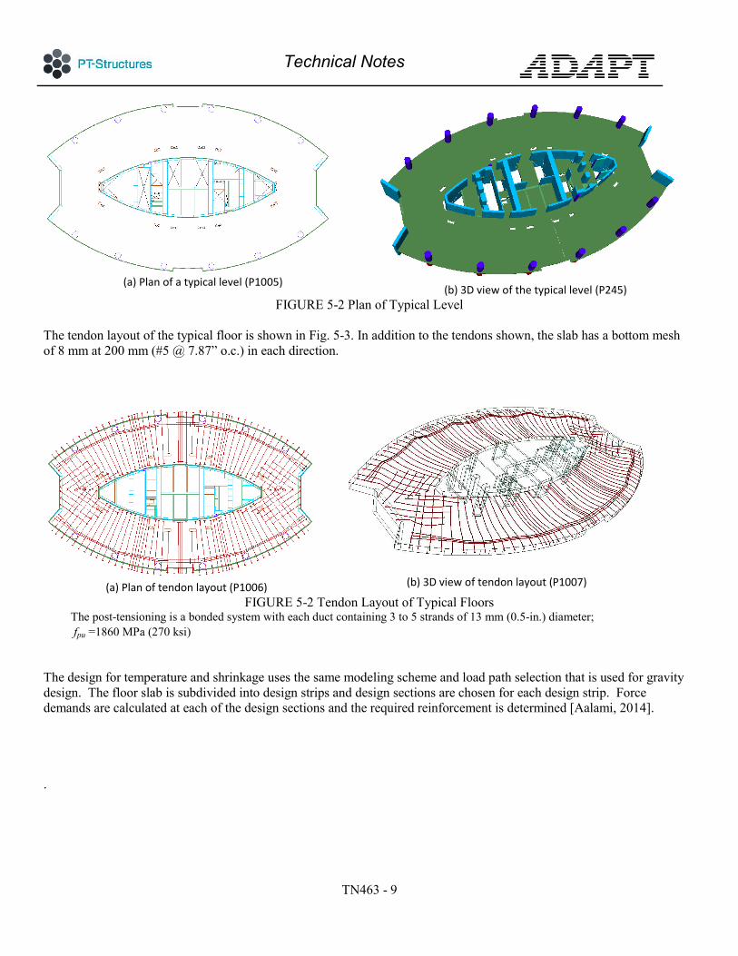
(a) Plan of a typical level (P1005)
(b) 3D view of the typical level (P245) FIGURE 5-2 Plan of Typical Level
The tendon layout of the typical floor is shown in Fig. 5-3. In addition to the tendons shown, the slab has a bottom mesh of 8 mm at 200 mm (#5 @ 7.87” o.c.) in each direction.
(a) Plan of tendon layout (P1006)
(b) 3D view of tendon layout (P1007)
FIGURE 5-2 Tendon Layout of Typical Floors The post-tensioning is a bonded system with each duct containing 3 to 5 strands of 13 mm (0.5-in.) diameter; fpu =1860 MPa (270 ksi)
The design for temperature and shrinkage uses the same modeling scheme and load path selection that is used for gravity design. The floor slab is subdivided into design strips and design sections are chosen for each design strip. Force demands are calculated at each of the design sections and the required reinforcement is determined [Aalami, 2014]. .
Technical Notes
TN463 - 10
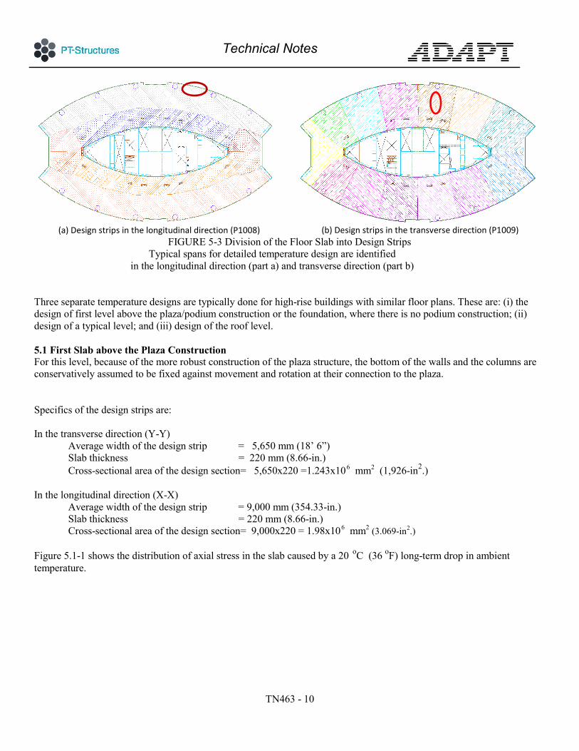
(a) Design strips in the longitudinal direction (P1008)
(b) Design strips in the transverse direction (P1009)
FIGURE 5-3 Division of the Floor Slab into Design Strips Typical spans for detailed temperature design are identified
in the longitudinal direction (part a) and transverse direction (part b) Three separate temperature designs are typically done for high-rise buildings with similar floor plans. These are: (i) the design of first level above the plaza/podium construction or the foundation, where there is no podium construction; (ii) design of a typical level; and (iii) design of the roof level. 5.1 First Slab above the Plaza Construction For this level, because of the more robust construction of the plaza structure, the bottom of the walls and the columns are conservatively assumed to be fixed against movement and rotation at their connection to the plaza. Specifics of the design strips are: In the transverse direction (Y-Y)
Average width of the design strip = 5,650 mm (18’ 6”) Slab thickness = 220 mm (8.66-in.) Cross-sectional area of the design section= 5,650x220 =1.243x106 mm2 (1,926-in2.)
In the longitudinal direction (X-X)
Average width of the design strip = 9,000 mm (354.33-in.) Slab thickness = 220 mm (8.66-in.) Cross-sectional area of the design section= 9,000x220 = 1.98x106 mm2 (3.069-in2.)
Figure 5.1-1 shows the distribution of axial stress in the slab caused by a 20 oC (36 oF) long-term drop in ambient temperature.
C

Technical Notes
TN463 - 11
(a) Axial stresses in the long direction (P1010)
(b) Axial stress in the short direction (P1011)
FIGURE 5.1-1 Distribution of axial stress in the first level above the plaza construction from a drop of 20 oC (36 oF) in ambient temperature. Stresses shown are in MPa. Tension is shown positive. The wall and column supports are assumed fixed against movement and rotation at their connection to the podium. The axial stresses shown are additive to those from gravity and other loads. (1 MPa = 145 psi)
(a) Axial stress for service condition (P1012)
(b) Axial stress for service condition; drop in temperature (P1013)
FIGURE 5.1-2 Distribution of axial stress in the first level above the podium. The values shown are the stresses along the support lines of the design strips in Fig. 5-3 for the sustained service (quasi permanent) load combination plus 20 oC drop in ambient temperature. Stresses shown are in MPa. Tension is positive. At the critical location of the longitudinal direction (X-direction), the initial precompression of -0.52 MPa at midspan has become a tensile stress of 1.69 MPa. Temperature reinforcement will be required at this location. (1 MPa = 145 psi)
A- Transverse Direction: In the transverse (Y-Y) direction, the precompression at midspan is reduced from 2.00 MPa compression to 1.09 MPa compression. The reduced amount still exceeds the threshold of 0.67 MPa compression that would trigger the requirement of additional reinforcement for temperature control. Hence, no additional rebar is necessary in the radial direction.

Technical Notes
TN463 - 12
B – Longitudinal Direction: In the longitudinal direction (X-X), the value of 0.52 MPa compression is reduced to 1.69 MPa tension by the drop in temperature. ACI 318’s provision for temperature and shrinkage reinforcement is based on the premise that shrinkage and a drop in temperature will result in crack formation, which will mobilize the recommended reinforcement to control crack width. In this case, since there will be no contribution from precompression, the required reinforcement is given by: As = 0.0018Ac = 0.0018x220x1000 = 396 mm2/m Reinforcement from the provided bottom mesh of 8 mm@200 mm each way As,provided = 5x50.3 = 251.1 mm2 < 396 mm2/m Hence, additional reinforcement is required. Per ACI 318, the spacing of the reinforcement should not be greater than 450 mm. Since the bonded tendons are grouped along the boundary of the floor, their contribution at distances farther than 450 mm is not accounted for in crack control. Distributed reinforcement is required to cover the shortfall of reinforcement on this level. Provide 10 mm bars @ 150 mm o.c. As,prov = 523 mm2/m > 396 mm2/m OK 5.2 Typical Levels With respect to design, the primary difference between the typical levels and the first level above the podium are the support conditions at the far end of the supports. For the typical levels, the far end of the supports is effectively free to move horizontally, since they rest on a slab of similar conditions with respect to the tendency to shorten. However, as with the first level above the podium, the ends of the supports are assumed rotationally fixed. The 20 Co drop in ambient temperature will result in the distribution of axial stresses shown in Fig. 5.2-1
(a) Axial stresses in the long direction (P2014)
(b) Axial stress in the short direction (P2015)
FIGURE 5.2-1 Distribution of axial stress from a drop of 20 oC in ambient temperature in the typical level. Stresses shown are in MPa. Tension is shown positive. The bottom of the wall and column supports are assumed free to move horizontally, but are rotationally
fixed. The distributions show development of tension in both the longitudinal and transverse direction from the temperature drop.

Technical Notes
TN463 - 13
(a) Axial stress for service condition (P1016)
(b) Axial stress for service condition and drop in
temperature (P1017) FIGURE 5.1-2 Distribution of Axial Stress from Drop of 20 oC in Ambient Temperature
The drop in temperature has negligible impact on the stresses in the transverse direction, but reduces the precompression in the longitudinal direction due to the greater impact of core walls on the shortening in this direction. (1 MPa = 145 psi)
A- Transverse Direction: In the transverse direction (Y-Y), the compressive stresses at midspan increase from 2.39 MPa compression to 2.41 MPa compression. The increase in compression is not significant. B – Longitudinal Direction: In longitudinal (X-X) direction, the temperature drop reduces the axial compression of the service condition from 0.72 to 0.58 MPa. Hence, temperature reinforcement is required. Since the post-tensioning tendons are banded along the perimeter (Fig. 5-2), they do not meet the requirement for a maximum spacing of 450 mm. Hence, the entire reinforcement will be provided by well-distributed non-prestressed reinforcement. As = 0.0018Ac = 0.0018x220x1000 = 396 mm2/m The plans show a bottom mesh of 8 mm@200 mm each way. As,provided = 5x50.3 = 251.1 mm2 < 396 mm2/m Additional bottom steel is required. Change the bottom mesh to 10 mm @150 mm o.c. As,prov = 523 mm2/m > 396 mm2/m OK 5.3 Roof Level The exposed surface of the roof slab experiences a daily change of temperature through its depth. The temperature gradient will depend primarily on the insulation of the roof cover and the slab depth. In the absence of specific data for the project, a 10 oC temperature difference between the two faces of the roof slab is considered. In effect, the roof slab will be subject to a temperature gradient with 10 oC.
The distribution of stress due to the rise in temperature at the top surface of the roof slab is shown in Fig. 5.3-1
Technical Notes
TN463 - 14
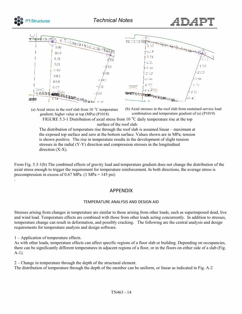
(a) Axial stress in the roof slab from 10 oC temperature gradient; higher value at top (MPa) (P1018)
(b) Axial stresses in the roof slab from sustained service load combination and temperature gradient of (a) (P1019)
FIGURE 5.3-1 Distribution of axial stress from 10 oC daily temperature rise at the top surface of the roof slab.
The distribution of temperature rise through the roof slab is assumed linear – maximum at the exposed top surface and zero at the bottom surface. Values shown are in MPa; tension is shown positive. The rise in temperature results in the development of slight tension stresses in the radial (Y-Y) direction and compression stresses in the longitudinal direction (X-X).
From Fig. 5.3-1(b) The combined effects of gravity load and temperature gradient does not change the distribution of the axial stress enough to trigger the requirement for temperature reinforcement. In both directions, the average stress is precompression in excess of 0.67 MPa. (1 MPa = 145 psi) .
APPENDIX
TEMPERATURE ANALYSIS AND DESIGN AID
Stresses arising from changes in temperature are similar to those arising from other loads, such as superimposed dead, live and wind load. Temperature effects are combined with those from other loads acting concurrently. In addition to stresses, temperature change can result in deformation, and possibly cracking. The following are the central analysis and design requirements for temperature analysis and design software. 1 – Application of temperature effects. As with other loads, temperature effects can affect specific regions of a floor slab or building. Depending on occupancies, there can be significantly different temperatures in adjacent regions of a floor, or in the floors on either side of a slab (Fig. A-1). 2 – Change in temperature through the depth of the structural element. The distribution of temperature through the depth of the member can be uniform, or linear as indicated in Fig. A-2

Technical Notes
TN463 - 15
3 - The change in temperature can take place over a relatively long period, such as seasonal changes, or can be short term, such as daily. The effects will be different and need to be accounted for differently in load calculations. 4 – Temperature effects must be combined with the effects of other loads on the structure. Reinforcement specified for other load conditions should be evaluated and adjusted as required for temperature effects. 5 – When detailing temperature reinforcement, bonded post-tensioning tendons should be taken into account. Their effectiveness is limited to the distance recommended for spacing of temperature reinforcement,
FIGURE A-1 Plan: Different Regions of a Floor Subject to Different Temperatures
FIGURE A-2 Distribution of Temperature through Depth of Member (a) shows uniform distribution of temperature. (b) shows a linear
distribution of temperature through the depth
REFERENCES Aalami, B. O., (2014), ”Post-Tensioned Buildings, Design and Construction,” www.PT-Structures.com, Redwood City, California. ACI 318-11, (2011),”Building Code Requirements for Structural Concrete and Commentary,” American Concrete Institute, ACI, www.concrete.org. ADAPT Builder, 2015,”Computer Program for Analysis and Design of Conventionally Reinforced, or Post-Tensioned Floor Systems,” ADAPT Corporation, www.adaptsoft.com, Redwood City, CA

Technical Notes
TN463 - 16
www.ADAPTsoft.com www.PT-Structures.com This publication is intended for the use of professionals competent to evaluate the significance and limitations of its contents and who will accept responsibility for the application of the materials it contains. The author and the affiliated organizations report the foregoing material as a matter of information and therefore disclaim any and all responsibility for application of the stated principles and procedures or for the accuracy of the sources. The author and the affiliated organizations in publishing these Technical Notes make no warranty regarding the recommendations contained herein, including warranties of quality, workmanship or safety, express or implied, further not limited to, implied warranties or merchantability and fitness for a particular purpose.