TN Technical Manual - bbp.stylebbp.style/.../terracade/TR-Terracade-TNTechnicalManual-NAT.pdf ·...
72
AUSTRALIA TERRAÇADE TN technical manual – fifth edition DECEMBER 2017
Transcript of TN Technical Manual - bbp.stylebbp.style/.../terracade/TR-Terracade-TNTechnicalManual-NAT.pdf ·...

AUSTRALIA
TERRAÇADE TNtechnical manual – fifth edition
DECEMBER 2017


/ 3 /
fifth edition TECHNICAL MANUAL
CONTENTS
Page Section
04 01. Installation05 Safe Working Instructions06 Components
08 02. System Description
16 03. Structural Performance
30 04. Technical Specifications31 Materials Schedule and Properties33 Fasteners35 System Performance
36 05. Components
44 06. System Design – Common Details46 Overview47 Side Detail48 Horizontal Detail49 External Corner50 Internal Corner51 Base Detail52 Parapet53 Window Sill54 Window Head55 Window Jamb56 Window Reveal Option57 Set-Out Tool58 Rake Detail59 Top Restraint for Earthquake Zones60 Timber – Horizontal Detail61 Timber – Vertical Detail62 Timber – Termite Detail (Recessed Slab)63 Steel – Horizontal Detail64 Steel – Vertical Detail65 Concrete – Horizontal Detail66 Concrete – Vertical Detail67 Masonry – Horizontal Detail68 Masonry – Vertical Detail69 Membrane
71 07. Maintenance Guide
For the most up to date information on Terraçade products and the latest version of this manual, please refer to our website. www.terracade.com.au

/ 4 /
TERRAÇADE TN
INSTALLATION
1For the most up to date information on Terraçade products and the latest version
of this manual, please refer to our website; www.terracade.com.au

/ 5 /
SAFE WORKING INSTRUCTIONS:
Site Preperation
Reworking TilesSilica dust can be liberated from the Terraçade TN tiles when they are reworked. Chronic inhalation of crystalline silica has been associated with impairment of lung function. Please refer to SDS for Terraçade, which is available from the Terraçade website (www.terracade.com.au) for further information. Care should be taken when reworking Terraçade TN tiles to maintain the exposure to crystalline silica below the Exposure Standard proscribed by Worksafe Australia (0.1 mg/m3). Safe working procedures should include:
• Utilising a wet saw when cutting or reworking tiles. Contact the saw manufacturer for further details.
• Wear appropriate personal protective equipment, such as approved dust mask and safety goggles, when utilising power tools or abrasive hand tools on the tiles.
• Ensure that dust is disposed of during clean up and disposal appropriately, by either wetting or vacuuming. (refer to the below diagram).
Using Brick/Tile Saws or Power Saws• Ensure that adequate personal protective equipment, such
as approved safety glasses, gloves, dust mask and hearing protection, is worn.
• Try and use a wet saw to cut tiles, or ensure that adequate ventilation or dust extraction equipment is available if dry cutting is used.
Handling• Care should be taken when handling suspension rails and
trims to avoid cuts and abrasions. The use of appropriate gloves may be of benefit. Extra care should be taken when handling cut pieces of tiles.
• It is recommended that large packs of suspension rails should be broken up, so that they may be handled individually.
• Ensure clear passage when moving the suspension rails and trims due to their size. Also allow for adequate storage of the suspension rails and trims to avoid trip hazards.
• Take care when handling cut tiles, to avoid cuts or abrasions from sharp surfaces or broken tiles.
• Consider manual handling issues when lifting tiles.
• Ensure that an adequate number of people are available to support the weight of the roll when rolling out the membrane.
Surrounding Materials• All materials should be stored to avoid damage.
Particularly, ensure that the hangers on the suspension rails are protected from distortion and the edges and corners of the tiles are protected from chipping.
• Protect the tiles, rails and trims from exposure to rain, water or chemicals during storage.
• Ensure that pressure water jet cleaning of any surrounding surfaces is conducted prior to the installation of the tiles.
• Protect aluminium components during chemical cleaning of nearby materials, especially acid cleaning.
Face Masks P1 or P2 type approved to the relevant Australian Standards.
Hearing Protection approved to the relevant Australian Standards.
Safety Goggles approved to the relevant Australian Standards.
Clean up, wet down or vacuum Dispose containment of dust.
Recommended Safety Protection
fifth edition TECHNICAL MANUAL
/ 6 /
TERRAÇADE TN
INSTALLATION
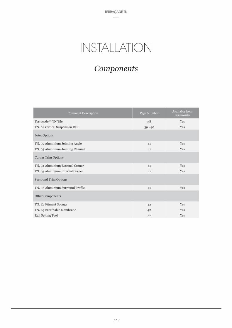
Components
Comment Description Page NumberAvailable from
Brickworks
Terraçade™ TN Tile 38 Yes
TN. 01 Vertical Suspension Rail 39 - 40 Yes
Joint Options
TN. 02 Aluminium Jointing Angle 41 Yes
TN. 03 Aluminium Jointing Channel 41 Yes
Corner Trim Options
TN. 04 Aluminium External Corner 41 Yes
TN. 05 Aluminium Internal Corner 41 Yes
Surround Trim Options
TN. 06 Aluminium Surround Profile 41 Yes
Other Components
TN. E2 Fitment Sponge 42 Yes
TN. E3 Breathable Membrane 42 Yes
Rail Setting Tool 57 Yes
/ 7 /
fifth edition TECHNICAL MANUAL
/ 8 /
TERRAÇADE TN
INSTALLATION
2For the most up to date information on Terraçade products and the latest version
of this manual, please refer to our website; www.terracade.com.au
/ 8 /
SYSTEM DESCRIPTION
2For the most up to date information on Terraçade products and the latest version
of this manual, please refer to our website; www.terracade.com.au
TERRAÇADE TN
/ 9 /
fifth edition TECHNICAL MANUAL
Terraçade TN has been designed in consultation with Australia’s leading engineers to act as a rain screen and rear ventilated façade system. It is a lightweight system and is simple to install.
System AssemblyThe Terraçade TN system is easily installed as the tiles are attached securely by a purpose designed vertical suspension rail. The system can be installed onto a timber framed, steel framed, concrete or masonry structural wall.
The Terraçade TN system is comprised of:
• A galvanised vertical suspension rail incorporating unique tile hangers,
• Lightweight clay tiles designed to fit securely onto the suspension rails,
• Two vertical jointing strip options,
• Fitment sponge,
• A waterproof membrane.
In addition, a full range of trims are available in anodised or powder coated finish to complement or highlight your design, including:
• Internal and external corners,
• A surround that accommodates windows, doors, bases and parapets.
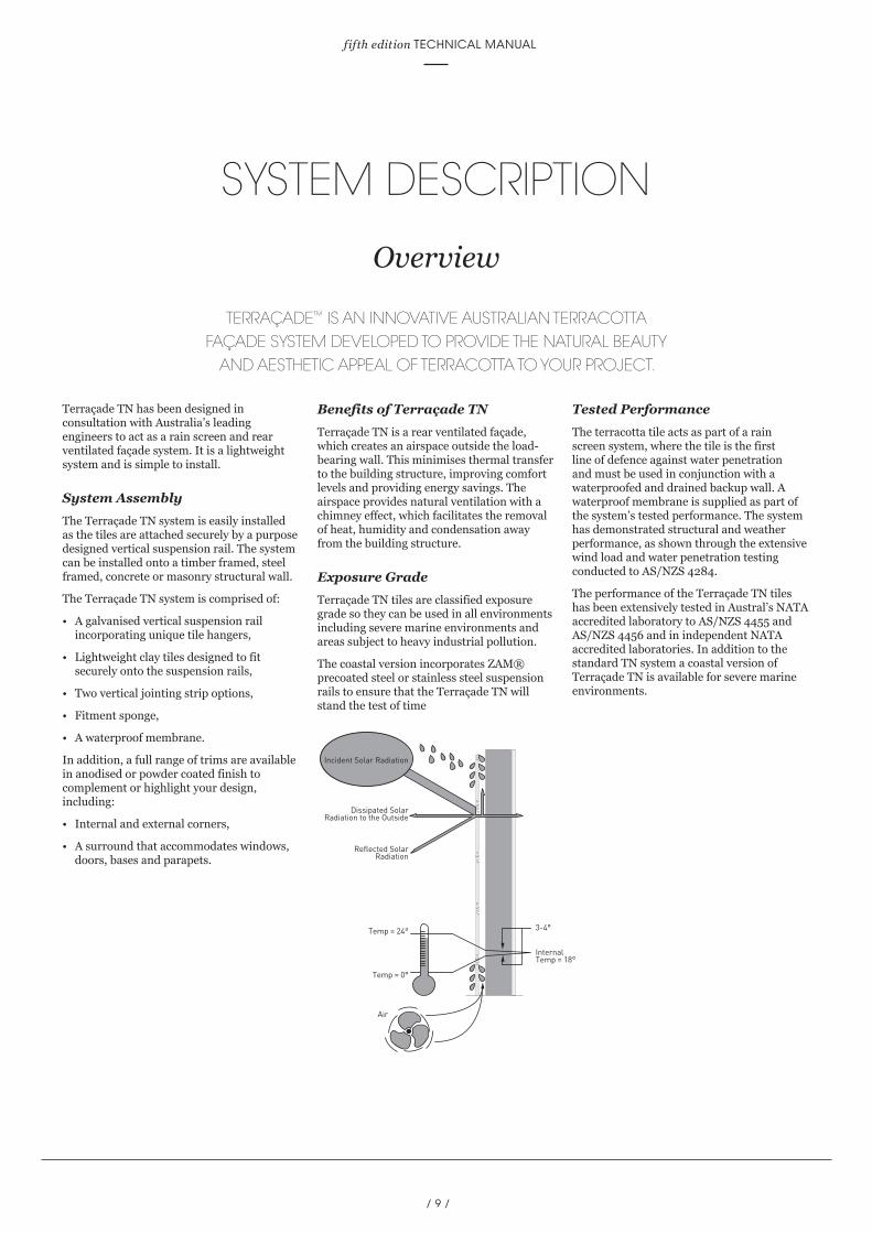
Benefits of Terraçade TNTerraçade TN is a rear ventilated façade, which creates an airspace outside the load-bearing wall. This minimises thermal transfer to the building structure, improving comfort levels and providing energy savings. The airspace provides natural ventilation with a chimney effect, which facilitates the removal of heat, humidity and condensation away from the building structure.
Exposure GradeTerraçade TN tiles are classified exposure grade so they can be used in all environments including severe marine environments and areas subject to heavy industrial pollution.
The coastal version incorporates ZAM® precoated steel or stainless steel suspension rails to ensure that the Terraçade TN will stand the test of time
Tested PerformanceThe terracotta tile acts as part of a rain screen system, where the tile is the first line of defence against water penetration and must be used in conjunction with a waterproofed and drained backup wall. A waterproof membrane is supplied as part of the system’s tested performance. The system has demonstrated structural and weather performance, as shown through the extensive wind load and water penetration testing conducted to AS/NZS 4284.
The performance of the Terraçade TN tiles has been extensively tested in Austral’s NATA accredited laboratory to AS/NZS 4455 and AS/NZS 4456 and in independent NATA accredited laboratories. In addition to the standard TN system a coastal version of Terraçade TN is available for severe marine environments.
SYSTEM DESCRIPTION
Overview
TERRAÇADE™ IS AN INNOVATIVE AUSTRALIAN TERRACOTTA FAÇADE SYSTEM DEVELOPED TO PROVIDE THE NATURAL BEAUTY
AND AESTHETIC APPEAL OF TERRACOTTA TO YOUR PROJECT.
Dissipated SolarRadiation to the Outside
Reflected SolarRadiation
Temp = 24°
Internal Temp = 18°
3-4°
Temp = 0°
Air
Incident Solar Radiation

/ 10 /
TERRAÇADE TN
SYSTEM DESCRIPTION
Terraçade TN System with Joint Channel
Joint Channel
Joint Channel
Terraçade TN tile 588mm
Terraçade TN suspension rail
600 600 600 600
301.
530
1.5
301.
530
1.5
1mm Gap
© Copyright 2017. Australian New Zealand Patent & Design Registrations. This drawing is indicative only and allowances should be made for material and onsite variations. The component and the assembly details demonstrate a design methodology only. Assembly and documentation drawings should only be undertaken after reference and compliance with the
relevant component’s technical data. The diagram is not to scale. For more tailored solutions to suit individual applications, please contact Brickworks Building Products. Brickworks Building Products reserves the rights to add, alter or delete components without prior notice.
ISSUE E-1117

/ 11 /
fifth edition TECHNICAL MANUAL
Terraçade TN tile 1188mm
Terraçade TN suspension rail
600 600 600 600
301.
530
1.5
301.
530
1.5
1mm GapJoint Channel
Joint Channel
SYSTEM DESCRIPTION
Terraçade TN System with Joint Channel
© Copyright 2017. Australian New Zealand Patent & Design Registrations. This drawing is indicative only and allowances should be made for material and onsite variations. The component and the assembly details demonstrate a design methodology only. Assembly and documentation drawings should only be undertaken after reference and compliance with the
relevant component’s technical data. The diagram is not to scale. For more tailored solutions to suit individual applications, please contact Brickworks Building Products. Brickworks Building Products reserves the rights to add, alter or delete components without prior notice.
ISSUE E-1117

/ 12 /
TERRAÇADE TN
SYSTEM DESCRIPTION
Terraçade TN System with Joint Angle
© Copyright 2017. Australian New Zealand Patent & Design Registrations. This drawing is indicative only and allowances should be made for material and onsite variations. The component and the assembly details demonstrate a design methodology only. Assembly and documentation drawings should only be undertaken after reference and compliance with the
relevant component’s technical data. The diagram is not to scale. For more tailored solutions to suit individual applications, please contact Brickworks Building Products. Brickworks Building Products reserves the rights to add, alter or delete components without prior notice.
ISSUE E-1117
592 592 592 592
Terraçade TN tile 588mm
Terraçade TN suspension rail
Joint Angle
Joint Angle
301.
530
1.5
301.
530
1.5

/ 13 /
fifth edition TECHNICAL MANUAL
SYSTEM DESCRIPTION
Terraçade TN System with Joint Angle
© Copyright 2017. Australian New Zealand Patent & Design Registrations. This drawing is indicative only and allowances should be made for material and onsite variations. The component and the assembly details demonstrate a design methodology only. Assembly and documentation drawings should only be undertaken after reference and compliance with the
relevant component’s technical data. The diagram is not to scale. For more tailored solutions to suit individual applications, please contact Brickworks Building Products. Brickworks Building Products reserves the rights to add, alter or delete components without prior notice.
ISSUE E-1117
596 596 596 596
Terraçade TN tile 1188mm
Terraçade TN suspension rail
301.
530
1.5
301.
530
1.5
Joint Angle
Joint Angle
/ 14 /
TERRAÇADE TN
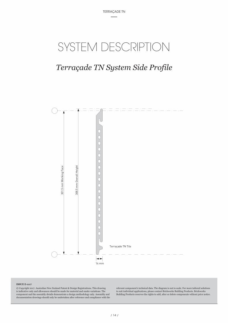
SYSTEM DESCRIPTION
Terraçade TN System Side Profile
© Copyright 2017. Australian New Zealand Patent & Design Registrations. This drawing is indicative only and allowances should be made for material and onsite variations. The component and the assembly details demonstrate a design methodology only. Assembly and documentation drawings should only be undertaken after reference and compliance with the
relevant component’s technical data. The diagram is not to scale. For more tailored solutions to suit individual applications, please contact Brickworks Building Products. Brickworks Building Products reserves the rights to add, alter or delete components without prior notice.
ISSUE E-1117
301.
5 m
m W
orki
ng F
ace
14 mm
Terraçade TN Tile
308.
5 m
m O
vera
ll H
eigh
t
/ 15 /
fifth edition TECHNICAL MANUAL

/ 16 /
TERRAÇADE TN
INSTALLATION
2For the most up to date information on Terraçade products and the latest version
of this manual, please refer to our website; www.terracade.com.au
/ 16 /
STRUCTURAL PERFORMANCE
3For the most up to date information on Terraçade products and the latest version
of this manual, please refer to our website; www.terracade.com.au
TERRAÇADE TN

/ 17 /
fifth edition TECHNICAL MANUAL
STRUCTURAL PERFORMANCE
System Performance for Earthquake and Wind Loads
Supply and Testing StatementThe Terraçade TN system has been tested to AS/NZS 4284 (Testing of building façades) for structural performance and has passed the deflection criteria under serviceable limit state.
System and structural advice has been obtained from Core Project Consulting (Australia) Pty. Ltd. and they have also provided engineering guidance on the structural testing.
Earthquake PerformanceThe Terraçade TN system has been checked for compliance with AS 1170: Part 4 Earthquake loads.
From analysis of AS 1170.4 the derived acceleration imparts a load which is approximately equal to the cladding self weight. When such loads are compared to the system’s allowable wind pressures it is evident that the wind load is the dominating load case.
As the Terraçade TN system develops small forces from the action of inertia during seismic events, the horizontal directions of movement are accommodated by the inherent strength of the system. No further action is therefore necessary to resist such movements, and the system is acceptable to AS 4100: 1998 Steel Structures.
Movement however in a true vertical direction does require restraint against the tiles lifting directly off the rail system under such an action.
For installation in earthquake prone areas, the Terraçade TN system requires an anti-lift block or trim installed along its top edge to ensure tiles under the action of vertical seismic events, are unable to detach from their supporting rail.
When the anti-lift block or trim is installed the system is suitable for installation against earthquakes in earthquake prone areas. However this precaution does not alleviate the system’s requirements for installation against wind load.
(Statement supplied by Core Project Consulting).
/ 18 /
TERRAÇADE TN
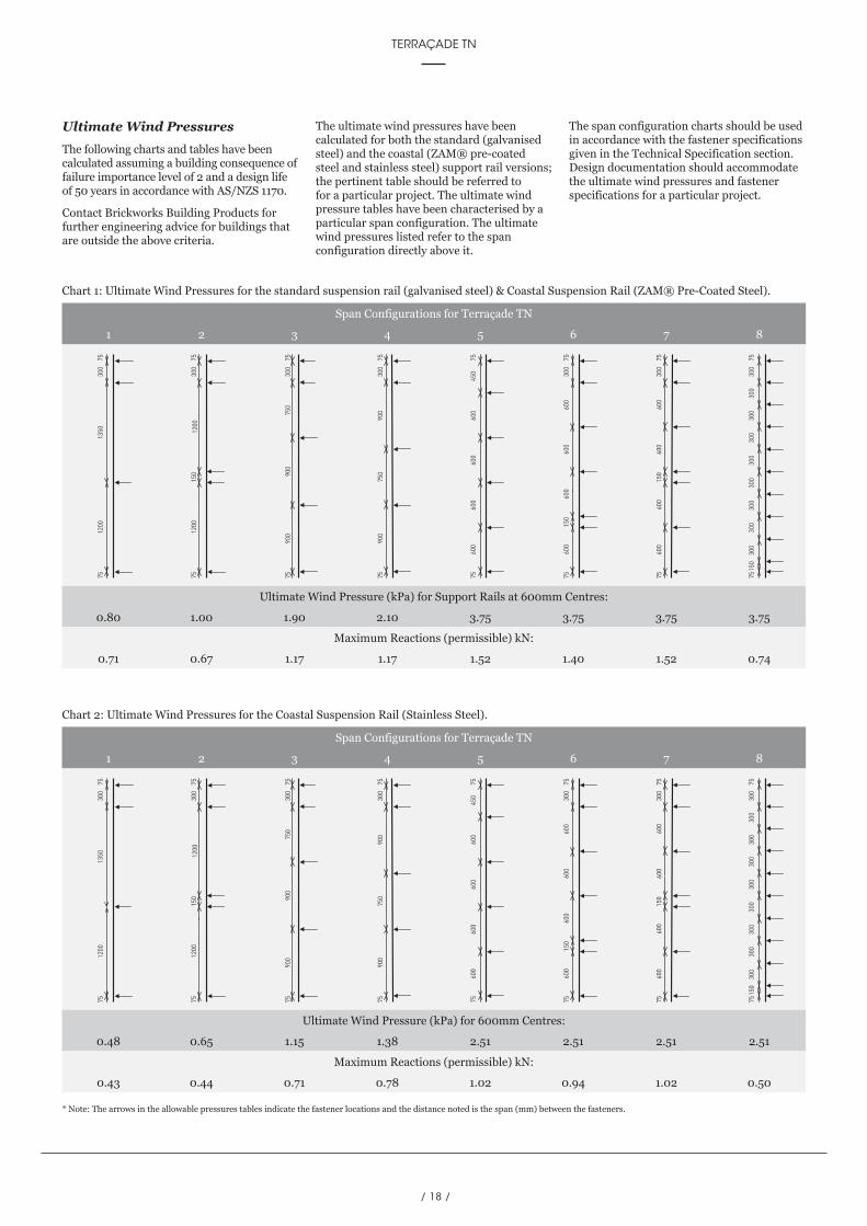
* Note: The arrows in the allowable pressures tables indicate the fastener locations and the distance noted is the span (mm) between the fasteners.
750
300
900
900
7575
900
750
900
7530
075
600
600
600
600
150
7575
300
600
600
150
600
600
7575
300
150
300
300
300
300
300
300
300
300
7575
300
450
600
600
600
7575
600
1200
1350
7575
300
1200
1200
150
7575
300
750
300
900
900
7575
900
750
900
7530
075
600
600
600
600
150
7575
300
600
600
150
600
600
7575
300
150
300
300
300
300
300
300
300
300
7575
300
450
600
600
600
7575
600
1200
1350
7575
300
1200
1200
150
7575
300
Span Configurations for Terraçade TN
1 2 3 4 5 6 7 8
Span Configurations for Terraçade TN
1 2 3 4 5 6 7 8
Ultimate Wind Pressure (kPa) for Support Rails at 600mm Centres:
0.80 1.00 1.90 2.10 3.75 3.75 3.75 3.75
Maximum Reactions (permissible) kN:
0.71 0.67 1.17 1.17 1.52 1.40 1.52 0.74
Ultimate Wind Pressure (kPa) for 600mm Centres:
0.48 0.65 1.15 1.38 2.51 2.51 2.51 2.51
Maximum Reactions (permissible) kN:
0.43 0.44 0.71 0.78 1.02 0.94 1.02 0.50
Chart 1: Ultimate Wind Pressures for the standard suspension rail (galvanised steel) & Coastal Suspension Rail (ZAM® Pre-Coated Steel).
Chart 2: Ultimate Wind Pressures for the Coastal Suspension Rail (Stainless Steel).
Ultimate Wind PressuresThe following charts and tables have been calculated assuming a building consequence of failure importance level of 2 and a design life of 50 years in accordance with AS/NZS 1170.
Contact Brickworks Building Products for further engineering advice for buildings that are outside the above criteria.
The ultimate wind pressures have been calculated for both the standard (galvanised steel) and the coastal (ZAM® pre-coated steel and stainless steel) support rail versions; the pertinent table should be referred to for a particular project. The ultimate wind pressure tables have been characterised by a particular span configuration. The ultimate wind pressures listed refer to the span configuration directly above it.
The span configuration charts should be used in accordance with the fastener specifications given in the Technical Specification section. Design documentation should accommodate the ultimate wind pressures and fastener specifications for a particular project.
/ 19 /
fifth edition TECHNICAL MANUAL
STRUCTURAL PERFORMANCE
System Performance for Wind Loads
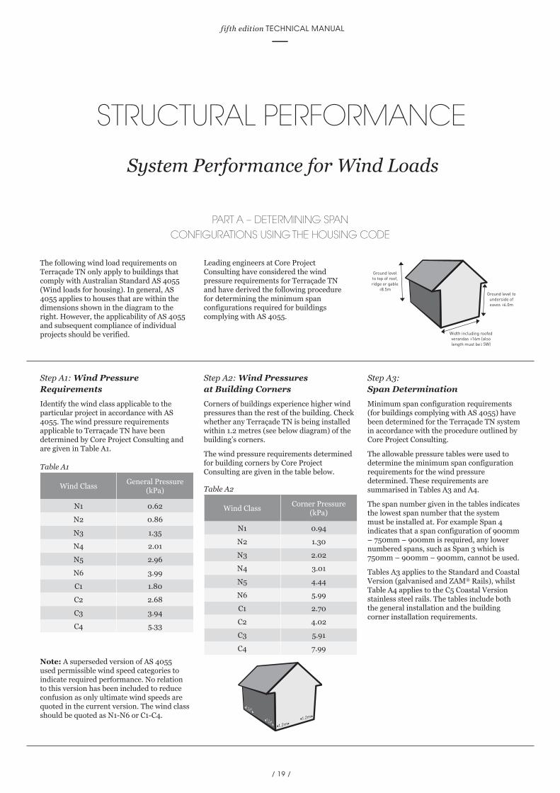
Ground level to underside of eaves 6.0m
Width including roofed verandas 16m (also length must be 5W)
Ground level to top of roof, ridge or gable
8.5m
The following wind load requirements on Terraçade TN only apply to buildings that comply with Australian Standard AS 4055 (Wind loads for housing). In general, AS 4055 applies to houses that are within the dimensions shown in the diagram to the right. However, the applicability of AS 4055 and subsequent compliance of individual projects should be verified.
Leading engineers at Core Project Consulting have considered the wind pressure requirements for Terraçade TN and have derived the following procedure for determining the minimum span configurations required for buildings complying with AS 4055.
Step A1: Wind Pressure RequirementsIdentify the wind class applicable to the particular project in accordance with AS 4055. The wind pressure requirements applicable to Terraçade TN have been determined by Core Project Consulting and are given in Table A1.
Note: A superseded version of AS 4055 used permissible wind speed categories to indicate required performance. No relation to this version has been included to reduce confusion as only ultimate wind speeds are quoted in the current version. The wind class should be quoted as N1-N6 or C1-C4.
Step A2: Wind Pressures at Building CornersCorners of buildings experience higher wind pressures than the rest of the building. Check whether any Terraçade TN is being installed within 1.2 metres (see below diagram) of the building’s corners.
The wind pressure requirements determined for building corners by Core Project Consulting are given in the table below.
Step A3: Span DeterminationMinimum span configuration requirements (for buildings complying with AS 4055) have been determined for the Terraçade TN system in accordance with the procedure outlined by Core Project Consulting.
The allowable pressure tables were used to determine the minimum span configuration requirements for the wind pressure determined. These requirements are summarised in Tables A3 and A4.
The span number given in the tables indicates the lowest span number that the system must be installed at. For example Span 4 indicates that a span configuration of 900mm – 750mm – 900mm is required, any lower numbered spans, such as Span 3 which is 750mm – 900mm – 900mm, cannot be used.
Tables A3 applies to the Standard and Coastal Version (galvanised and ZAM® Rails), whilst Table A4 applies to the C5 Coastal Version stainless steel rails. The tables include both the general installation and the building corner installation requirements.
PART A – DETERMINING SPAN CONFIGURATIONS USING THE HOUSING CODE
Wind ClassGeneral Pressure
(kPa)
N1 0.62
N2 0.86
N3 1.35
N4 2.01
N5 2.96
N6 3.99
C1 1.80
C2 2.68
C3 3.94
C4 5.33
Wind ClassCorner Pressure
(kPa)
N1 0.94
N2 1.30
N3 2.02
N4 3.01
N5 4.44
N6 5.99
C1 2.70
C2 4.02
C3 5.91
C4 7.99
1.2m1.2m
1.2m
1.2m
Table A1
Table A2

/ 20 /
TERRAÇADE TN
STRUCTURAL PERFORMANCE
System Performance for Wind Loads
Wind Class
Minimum Span Configuration Requirements
General Installation Building Corner Installation
N1 Span 1 Span 2
N2 Span 2 Span 3
N3 Span 3 Span 4
N4 Span 4 Span 5-8
N5 Span 5-8 N/A
N6 N/A N/A
C1 Span 3 Span 5-8
C2 Span 5-8 N/A
C3 N/A N/A
C4 N/A N/A
Wind Class
Minimum Span Configuration Requirements
General Installation Building Corner Installation
N1 Span 2 Span 3
N2 Span 3 Span 4
N3 Span 4 Span 5-8
N4 Span 5-8 N/A
N5 N/A N/A
N6 N/A N/A
C1 Span 5-8 N/A
C2 N/A N/A
C3 N/A N/A
C4 N/A N/A
Example 1A typical project has been determined to have a wind class of N1. If the standard version (galvanised rails) is required then using Table A3 the required span is Span 1 for general areas and Span 2 at the corners. It may be worthwhile for the project to specify the higher rated Span 2 for the entire project to simplify installation.
Note: It is important to remember that particular projects within C5 Corrosion Zone, require the coastal version stainless steel rails and therefore should use Table A4.
Note: The span configurations determined should be specified along with the fastener requirements in all project documentation.
Note: Terraçade TN standard (galvanised) and coastal (ZAM® pre-coated steel & stainless steel) rails that are cut to lengths of less than 1.8 m should always be installed at 600 mm centres.
Note: If a span configuration is ‘N/A’ for a particular wind class, use the analysis technique in Part B AS 1170.2. The scope of the wind pressure analysis performed in this housing section is limited and more detailed analysis is performed in Part B.
Standard & Coastal VersionTable A3: Minimum installation for 600mm centres (Galvanised and ZAM® Rails).
C5 Coastal VersionTable A4: Minimum installation for 600mm centres (Stainless Steel Rails).
*N/A equals Not Available *N/A equals Not Available
Suspension Rail Selection GuideTABLE A5: Suspension rail selection based on site atmospheric corrosivity.
* General guide only. Please refer to AS 4312-2008 for detailed corrosion zones.
Distance from Breaking Surf*Distance from Calm Salt
Water Body, eg. Bay*Corrosion Zone according
to AS 4312Recommended Suspension
Rail Material
1001m+ 101m+ Up to C3 Galvanised
501m to 1000m 0m to 100m Up to C4 ZAM® Pre-Coated Steel
0m to 500mm 0m to 100m Up to C5 304/316 Stainless Steel
/ 21 /
fifth edition TECHNICAL MANUAL
STRUCTURAL PERFORMANCE
System Performance for Wind Loads
PART B – DETERMINING SPAN CONFIGURATIONS USING THE STRUCTURAL DESIGN CODE
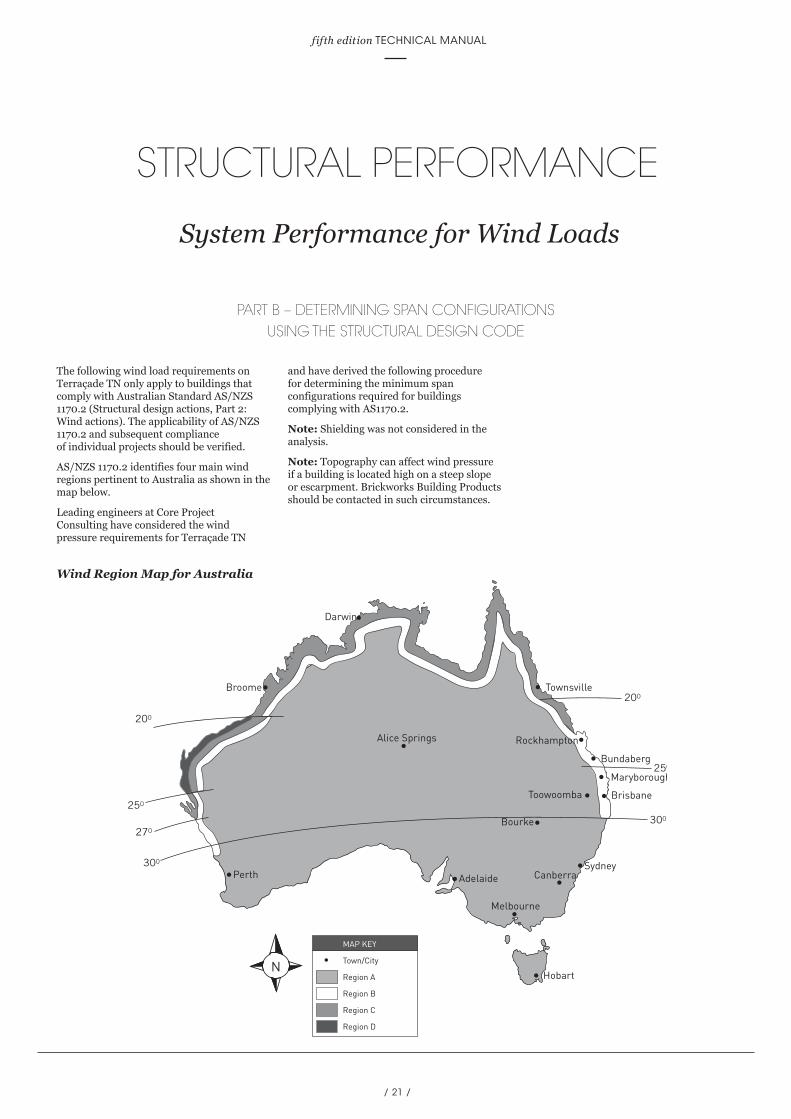
The following wind load requirements on Terraçade TN only apply to buildings that comply with Australian Standard AS/NZS 1170.2 (Structural design actions, Part 2: Wind actions). The applicability of AS/NZS 1170.2 and subsequent compliance of individual projects should be verified.
AS/NZS 1170.2 identifies four main wind regions pertinent to Australia as shown in the map below.
Leading engineers at Core Project Consulting have considered the wind pressure requirements for Terraçade TN
and have derived the following procedure for determining the minimum span configurations required for buildings complying with AS1170.2.
Note: Shielding was not considered in the analysis.
Note: Topography can affect wind pressure if a building is located high on a steep slope or escarpment. Brickworks Building Products should be contacted in such circumstances.
MAP KEY
Town/City
Region A
Region B
Region C
Region D
Townsville
Bundaberg
Maryborough
BrisbaneToowoomba
Bourke
Sydney
Hobart
Adelaide
Alice Springs
Perth300
270
250
200
300
250
Broome
Darwin
200
Rockhampton
Canberra
Melbourne
MAP KEY
Town/City
Region A
Region B
Region C
Region D
Townsville
Bundaberg
Maryborough
BrisbaneToowoomba
Bourke
Sydney
Hobart
Adelaide
Alice Springs
Perth300
270
250
200
300
250
Broome
Darwin
200
Rockhampton
Canberra
Melbourne MAP KEY
Town/City
Region A
Region B
Region C
Region D
Townsville
Bundaberg
Maryborough
BrisbaneToowoomba
Bourke
Sydney
Hobart
Adelaide
Alice Springs
Perth300
270
250
200
300
250
Broome
Darwin
200
Rockhampton
Canberra
Melbourne
Wind Region Map for Australia
/ 22 /
TERRAÇADE TN
STRUCTURAL PERFORMANCE
System Performance for Wind Loads
Step B1: Wind RegionIdentify the wind region that the project is located in. If the wind region has not been specified, it should be determined in accordance with AS/NZS 1170.2. The map indicates the wind regions for Australia. It is important to note that regions C and D are affected by cyclones and Terraçade TN are not recommanded for these regions.
Step B2: HeightDetermine the height above ground level to which the Terraçade TN will be installed. AS/NZS 1170.2 outlines the method of determining reference heights. The wind pressure requirements have been categorised by specific limiting heights. Always select the limiting height that is larger or equal to the project installation height.
Step B3: Terrain CategoryIdentify the terrain category for the project. The terrain will affect the wind flow that a project is subjected to. The four terrain categories defined in AS/NZS 1170.2 are:
• Category 1: Very few or no obstructions and an exposed open terrain.
• Category 1.5: Open water surfaces subjected to shoaling waves, e.g. near-shore ocean water; large unenclosed bays on seas and oceans; lakes; and enclosed bays extending greater than 10 km in the wind direction.
• Category 2: Limited and well-spread obstructions in an open terrain. Typical terrains include grasslands and water surfaces.
• Category 2.5: Terrain with a few trees or isolated obstructions, typical of developing outer urban areas with scattered houses, or large acreage developments with fewer than ten buildings per hectare.
• Category 3: Numerous low (3-5 m) obstructions that are closely spaced. A typical terrain is a suburban housing estate.
• Category 4: High number of large and tall (10-30 m) obstructions that are closely spaced. A typical terrain is a large city centre.
Note: The terrain category should be determined in accordance with AS/NZS 1170.2 and obstructions should have permanence during a wind event.
Step B4: Wind PressureA wind pressure table (Table B1) has been provided as a reference. The wind pressure for an individual project can be determined from the table using the information determined in the preceding steps.
Example 1:A typical project in a suburban area of Brisbane (i.e. Terrain Category 3, Region B) installed to a height of 4m. For this case using the limiting height of 10m, the wind pressure for Terraçade TN is 1.63 kPa (using Table B1).
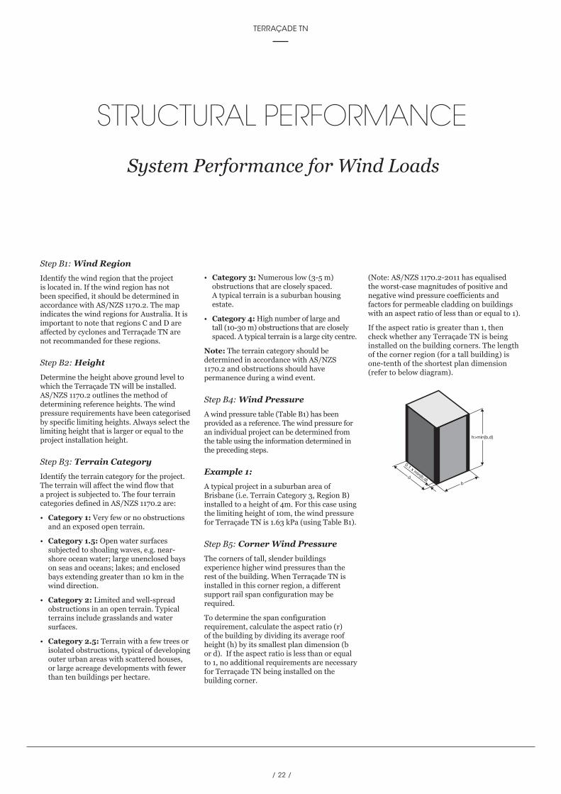
Step B5: Corner Wind PressureThe corners of tall, slender buildings experience higher wind pressures than the rest of the building. When Terraçade TN is installed in this corner region, a different support rail span configuration may be required.
To determine the span configuration requirement, calculate the aspect ratio (r) of the building by dividing its average roof height (h) by its smallest plan dimension (b or d). If the aspect ratio is less than or equal to 1, no additional requirements are necessary for Terraçade TN being installed on the building corner.
(Note: AS/NZS 1170.2-2011 has equalised the worst-case magnitudes of positive and negative wind pressure coefficients and factors for permeable cladding on buildings with an aspect ratio of less than or equal to 1).
If the aspect ratio is greater than 1, then check whether any Terraçade TN is being installed on the building corners. The length of the corner region (for a tall building) is one-tenth of the shortest plan dimension (refer to below diagram).
h>min(b,d)
bd
0.1 x min(b,d)
/ 23 /
fifth edition TECHNICAL MANUAL
Example 2:A six storey building has plan dimensions of 32 metres and 16 metres, and has an average roof height of 20 metres. The aspect ratio found by dividing the height of 20m by the smallest plan dimension i.e., 16m, which equals 1.25. Since the aspect ratio is greater than 1, additional fixings for the Terraçade TN support rails are required at the corners of the building for the increased wind pressure.
The distance from the corners of the building requiring additional fixings for the Terraçade TN support rails is one-tenth of the shortest plan dimension, which in this example is 0.1 x 16 = 1.6 metres. This must be rounded up to a multiple of 600mm (support rail spacing), for this example, the distance from the corners of the building requiring additional support fixings is 1.8m.
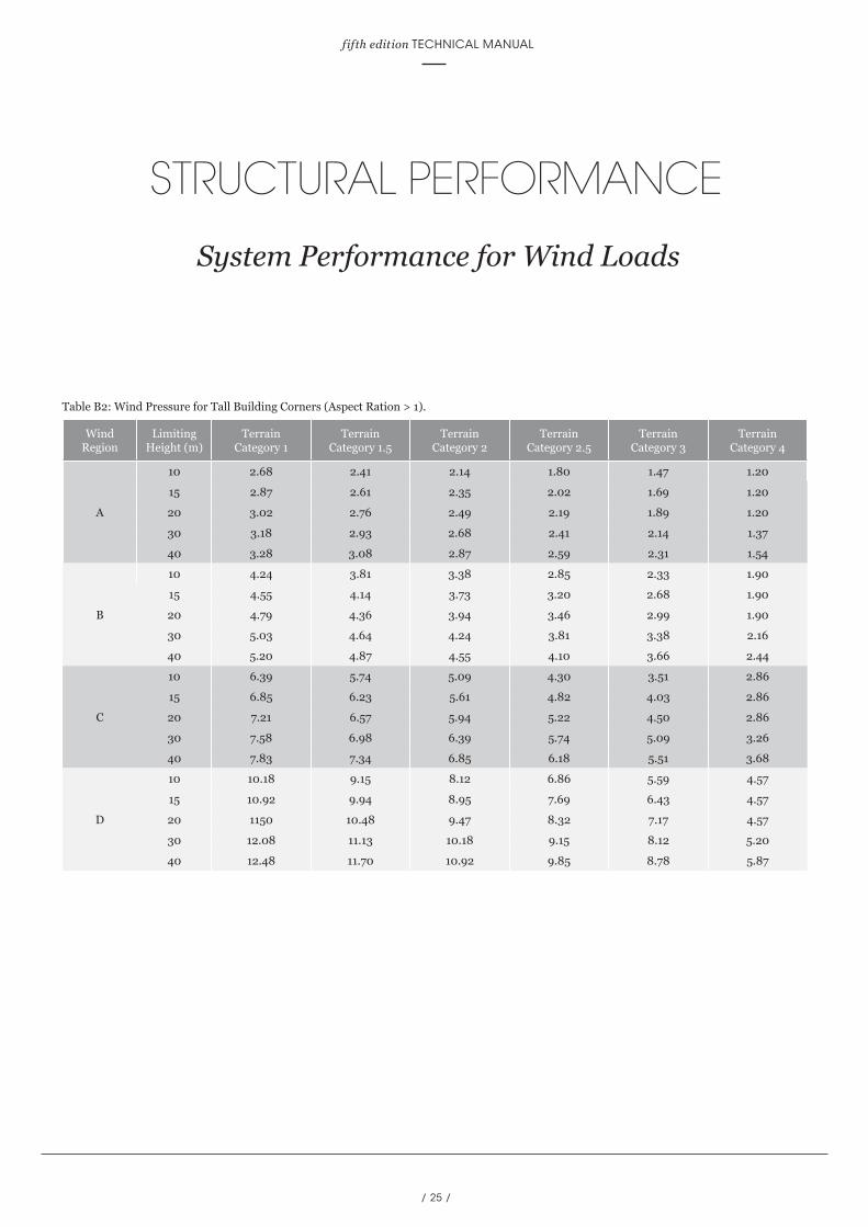
A wind pressure table (Table B2) has been provided as a reference for the wind pressure at the building corners.
Example 3:A medium-rise project in the central business district of Brisbane (i.e. Terrain Category 4, Region B) is installed to a height of 30m, with an aspect ratio of grater than one.
For this case, the wind pressure for general areas of Terraçade TN for a limiting height of 30m is1.52kPa (using Table B1) and the wind pressure on at the corners is 2.16kPa (using Table B2).
The minimum span fastener configuration for general installation a can be read from Table B3 for 600 mm centres (e.g., span configuration 3, for a height of 30 m in this example).
The minimum span fastener configuration for corner installation can be read from Table B4 for 600mm centres (e.g. span configurations 5 to 8, for a height of 30m in this example).
However, it is recommended to adopt the higher rated span 5 to 8 configuration for the entire project to simplify installation.
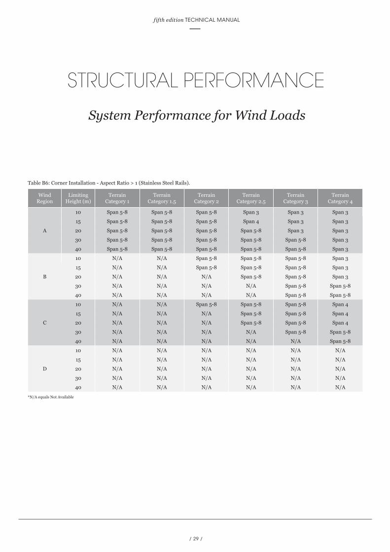
Step B6: Span DeterminationMinimum span configuration requirements (for buildings complying with AS/NZS 1170.2) have been determined for the Terraçade TN system in accordance with the procedure outlined by Core Project Consulting. The allowable pressure tables were used to determine the minimum span configuration requirements for the wind pressure determined. These requirements are summarised in Tables B3-B6.
The span number given in the tables indicates the lowest span number that the system must be installed at. For example Span 4 indicates that a span configuration of 900mm – 750mm – 900mm is required (refer to span diagram below), any lower numbered spans, such as Span 3 which is 750mm – 900mm – 900mm, cannot be used.
Table B3 and B4 apply to the Standard and Coastal Version(galvanised and ZAM® Rails). Table B5 and B6 apply to the C5 Coastal Version (Stainless steel rails).
Note: It is important to remember that particular projects that require the C5 coastal version (stainless steel rails) should use Tables B5 and B6.
Note: The span configurations determined should be specified along with the fastener requirements (refer to the Technical Specifications - Fastener Section) in all project documentation.
Note: Terraçade TN rails that are cut to lengths of less than 1.8m should always be installed at 600mm centres.
STRUCTURAL PERFORMANCE
System Performance for Wind Loads

/ 24 /
TERRAÇADE TN
STRUCTURAL PERFORMANCE
System Performance for Wind Loads
* Note: The arrows in the allowable pressures tables indicate the fastener locations and the distance noted is the span (mm) between the fasteners.
750
300
900
900
7575
900
750
900
7530
075
600
600
600
600
150
7575
300
600
600
150
600
600
7575
300
150
300
300
300
300
300
300
300
300
7575
300
450
600
600
600
7575
600
1200
1350
7575
300
1200
1200
150
7575
300
Wind Region
Limiting Height (m)
Terrain Category 1
Terrain Category 1.5
Terrain Category 2
Terrain Category 2.5
Terrain Category 3
Terrain Category 4
A
10 1.88 1.69 1.50 1.26 1.03 0.84
15 2.01 1.83 1.65 1.42 1.19 0.84
20 2.12 1.93 1.75 1.53 1.32 0.84
30 2.23 2.05 1.88 1.69 1.50 0.96
40 2.30 2.16 2.01 1.82 1.62 1.08
B
10 2.97 2.67 2.37 2.00 1.63 1.33
15 3.19 2.90 2.61 2.24 1.88 1.33
20 3.35 3.06 2.76 2.43 2.09 1.33
30 3.53 3.25 2.97 2.67 2.37 1.52
40 3.64 3.41 3.19 2.87 2.56 1.71
C
10 4.48 4.02 3.57 3.01 2.46 2.01
15 4.80 4.37 3.93 3.38 2.83 2.01
20 5.05 4.61 4.16 3.66 3.15 2.01
30 5.31 4.89 4.48 4.02 3.57 2.28
40 5.49 5.14 4.80 4.33 3.86 2.58
D
10 7.14 6.41 5.69 4.80 3.92 3.20
15 7.66 6.96 6.27 5.39 4.51 3.20
20 8.06 7.35 6.64 5.83 5.03 3.20
30 8.47 7.80 7.14 6.41 5.69 3.64
40 8.75 8.20 7.66 6.90 6.15 4.11
Table B1: Wind Pressure.
Chart 3: Span Configurations for Terraçade TN
Span Configurations for Terraçade TN
1 2 3 4 5 6 7 8
/ 25 /
fifth edition TECHNICAL MANUAL
STRUCTURAL PERFORMANCE
System Performance for Wind Loads
Wind Region
Limiting Height (m)
Terrain Category 1
Terrain Category 1.5
Terrain Category 2
Terrain Category 2.5
Terrain Category 3
Terrain Category 4
A
10 2.68 2.41 2.14 1.80 1.47 1.20
15 2.87 2.61 2.35 2.02 1.69 1.20
20 3.02 2.76 2.49 2.19 1.89 1.20
30 3.18 2.93 2.68 2.41 2.14 1.37
40 3.28 3.08 2.87 2.59 2.31 1.54
B
10 4.24 3.81 3.38 2.85 2.33 1.90
15 4.55 4.14 3.73 3.20 2.68 1.90
20 4.79 4.36 3.94 3.46 2.99 1.90
30 5.03 4.64 4.24 3.81 3.38 2.16
40 5.20 4.87 4.55 4.10 3.66 2.44
C
10 6.39 5.74 5.09 4.30 3.51 2.86
15 6.85 6.23 5.61 4.82 4.03 2.86
20 7.21 6.57 5.94 5.22 4.50 2.86
30 7.58 6.98 6.39 5.74 5.09 3.26
40 7.83 7.34 6.85 6.18 5.51 3.68
D
10 10.18 9.15 8.12 6.86 5.59 4.57
15 10.92 9.94 8.95 7.69 6.43 4.57
20 1150 10.48 9.47 8.32 7.17 4.57
30 12.08 11.13 10.18 9.15 8.12 5.20
40 12.48 11.70 10.92 9.85 8.78 5.87
Table B2: Wind Pressure for Tall Building Corners (Aspect Ration > 1).

/ 26 /
TERRAÇADE TN
*N/A equals Not Available
STRUCTURAL PERFORMANCE
System Performance for Wind Loads
Wind Region
Limiting Height (m)
Terrain Category 1
Terrain Category 1.5
Terrain Category 2
Terrain Category 2.5
Terrain Category 3
Terrain Category 4
A
10 Span 3 Span 3 Span 3 Span 3 Span 3 Span 2
15 Span 4 Span 3 Span 3 Span 3 Span 3 Span 2
20 Span 5-8 Span 4 Span 3 Span 3 Span 3 Span 2
30 Span 5-8 Span 4 Span 3 Span 3 Span 3 Span 2
40 Span 5-8 Span 5-8 Span 4 Span 3 Span 3 Span 3
B
10 Span 5-8 Span 5-8 Span 5-8 Span 4 Span 3 Span 3
15 Span 5-8 Span 5-8 Span 5-8 Span 5-8 Span 3 Span 3
20 Span 5-8 Span 5-8 Span 5-8 Span 5-8 Span 4 Span 3
30 Span 5-8 Span 5-8 Span 5-8 Span 5-8 Span 5-8 Span 3
40 Span 5-8 Span 5-8 Span 5-8 Span 5-8 Span 5-8 Span 3
C
10 N/A N/A Span 5-8 Span 5-8 Span 5-8 Span 4
15 N/A N/A N/A Span 5-8 Span 5-8 Span 4
20 N/A N/A N/A Span 5-8 Span 5-8 Span 4
30 N/A N/A N/A N/A Span 5-8 Span 5-8
40 N/A N/A N/A N/A N/A Span 5-8
D
10 N/A N/A N/A N/A N/A Span 5-8
15 N/A N/A N/A N/A N/A Span 5-8
20 N/A N/A N/A N/A N/A Span 5-8
30 N/A N/A N/A N/A N/A Span 5-8
40 N/A N/A N/A N/A N/A N/A
Table B3: General Installation (ZAM® Pre-Coated Steel and Galvanised Rails).

/ 27 /
fifth edition TECHNICAL MANUAL
STRUCTURAL PERFORMANCE
System Performance for Wind Loads
*N/A equals Not Available
Wind Region
Limiting Height (m)
Terrain Category 1
Terrain Category 1.5
Terrain Category 2
Terrain Category 2.5
Terrain Category 3
Terrain Category 4
A
10 Span 5-8 Span 5-8 Span 5-8 Span 3 Span 3 Span 3
15 Span 5-8 Span 5-8 Span 5-8 Span 4 Span 3 Span 3
20 Span 5-8 Span 5-8 Span 5-8 Span 5-8 Span 3 Span 3
30 Span 5-8 Span 5-8 Span 5-8 Span 5-8 Span 5-8 Span 3
40 Span 5-8 Span 5-8 Span 5-8 Span 5-8 Span 5-8 Span 3
B
10 N/A N/A Span 5-8 Span 5-8 Span 5-8 Span 3
15 N/A N/A Span 5-8 Span 5-8 Span 5-8 Span 3
20 N/A N/A N/A Span 5-8 Span 5-8 Span 3
30 N/A N/A N/A N/A Span 5-8 Span 5-8
40 N/A N/A N/A N/A Span 5-8 Span 5-8
C
10 N/A N/A Span 5-8 Span 5-8 Span 5-8 Span 4
15 N/A N/A N/A Span 5-8 Span 5-8 Span 4
20 N/A N/A N/A Span 5-8 Span 5-8 Span 4
30 N/A N/A N/A N/A Span 5-8 Span 5-8
40 N/A N/A N/A N/A N/A Span 5-8
D
10 N/A N/A N/A N/A N/A N/A
15 N/A N/A N/A N/A N/A N/A
20 N/A N/A N/A N/A N/A N/A
30 N/A N/A N/A N/A N/A N/A
40 N/A N/A N/A N/A N/A N/A
Table B4: Corner Installation - Aspect Ratio > 1 (ZAM® Pre-Coated Steel and Galvanised Rails).

/ 28 /
TERRAÇADE TN
STRUCTURAL PERFORMANCE
System Performance for Wind Loads
*N/A equals Not Available
Wind Region
Limiting Height (m)
Terrain Category 1
Terrain Category 1.5
Terrain Category 2
Terrain Category 2.5
Terrain Category 3
Terrain Category 4
A
10 Span 5-8 Span 5-8 Span 5-8 Span 4 Span 3 Span 3
15 Span 5-8 Span 5-8 Span 5-8 Span 5-8 Span 4 Span 3
20 Span 5-8 Span 5-8 Span 5-8 Span 5-8 Span 4 Span 3
30 Span 5-8 Span 5-8 Span 5-8 Span 5-8 Span 5-8 Span 3
40 Span 5-8 Span 5-8 Span 5-8 Span 5-8 Span 5-8 Span 3
B
10 N/A N/A Span 5-8 Span 5-8 Span 5-8 Span 4
15 N/A N/A N/A Span 5-8 Span 5-8 Span 4
20 N/A N/A N/A Span 5-8 Span 5-8 Span 4
30 N/A N/A N/A N/A Span 5-8 Span 5-8
40 N/A N/A N/A N/A N/A Span 5-8
C
10 N/A N/A N/A N/A Span 5-8 Span 5-8
15 N/A N/A N/A N/A N/A Span 5-8
20 N/A N/A N/A N/A N/A Span 5-8
30 N/A N/A N/A N/A N/A Span 5-8
40 N/A N/A N/A N/A N/A N/A
D
10 N/A N/A N/A N/A N/A N/A
15 N/A N/A N/A N/A N/A N/A
20 N/A N/A N/A N/A N/A N/A
30 N/A N/A N/A N/A N/A N/A
40 N/A N/A N/A N/A N/A N/A
Table B5: General Installation (Stainless Steel Rails).
/ 29 /
fifth edition TECHNICAL MANUAL
STRUCTURAL PERFORMANCE
System Performance for Wind Loads
*N/A equals Not Available
Wind Region
Limiting Height (m)
Terrain Category 1
Terrain Category 1.5
Terrain Category 2
Terrain Category 2.5
Terrain Category 3
Terrain Category 4
A
10 Span 5-8 Span 5-8 Span 5-8 Span 3 Span 3 Span 3
15 Span 5-8 Span 5-8 Span 5-8 Span 4 Span 3 Span 3
20 Span 5-8 Span 5-8 Span 5-8 Span 5-8 Span 3 Span 3
30 Span 5-8 Span 5-8 Span 5-8 Span 5-8 Span 5-8 Span 3
40 Span 5-8 Span 5-8 Span 5-8 Span 5-8 Span 5-8 Span 3
B
10 N/A N/A Span 5-8 Span 5-8 Span 5-8 Span 3
15 N/A N/A Span 5-8 Span 5-8 Span 5-8 Span 3
20 N/A N/A N/A Span 5-8 Span 5-8 Span 3
30 N/A N/A N/A N/A Span 5-8 Span 5-8
40 N/A N/A N/A N/A Span 5-8 Span 5-8
C
10 N/A N/A Span 5-8 Span 5-8 Span 5-8 Span 4
15 N/A N/A N/A Span 5-8 Span 5-8 Span 4
20 N/A N/A N/A Span 5-8 Span 5-8 Span 4
30 N/A N/A N/A N/A Span 5-8 Span 5-8
40 N/A N/A N/A N/A N/A Span 5-8
D
10 N/A N/A N/A N/A N/A N/A
15 N/A N/A N/A N/A N/A N/A
20 N/A N/A N/A N/A N/A N/A
30 N/A N/A N/A N/A N/A N/A
40 N/A N/A N/A N/A N/A N/A
Table B6: Corner Installation - Aspect Ratio > 1 (Stainless Steel Rails).

/ 30 /
TERRAÇADE TN
INSTALLATION
2For the most up to date information on Terraçade products and the latest version
of this manual, please refer to our website; www.terracade.com.au
/ 30 /
TECHNICAL SPECIFICATIONS
4For the most up to date information on Terraçade products and the latest version
of this manual, please refer to our website; www.terracade.com.au
TERRAÇADE TN

/ 31 /
fifth edition TECHNICAL MANUAL
TECHNICAL SPECIFICATIONS
Materials Schedule and Properties
* Brickworks Building Products reserves the right to change specifications without notice – November 2017. Check the Terraçade website for updated results. ZAM® is a registered trade mark of Nisshin Steel.
Component Material
01. Tiles Fired extruded clay tile.
02. Suspension RailStandard - Galvanised (cold formed light galvanised sheet), or C4 Coastal - ZAM® pre-coated steel, or C5 Coastal - stainless steel sheet grade 316.
03. Visible Trims
Aluminium - All extrusions are aluminium Grade 6063-T5 and are produced to Australian Standard AS 1866 (Aluminium and Aluminium Allows - Extruded Rod, Bar, Solid and Hollow Shapes).
Trims are available in:
• Mill finish, which is expected to have a design life in excess of twenty-five years for moderate environments (as defined in AS/NZS 2312).
• Anodised finish in clear and black, which can have a design life in excess of forty years.
• Powder coated finish to AS 3715 in various colours, which can come with a guarantee of ten years.
Folded Metal Trims – These trims are available in Colourbond® or alternative finishes from other suppliers.
04. Waterproof MembraneFor framed systems a waterproof membrane can be supplied as part of the system’s tested performance. The membrane is a spunbonded polypropylene material that allows the egress of vapour from within the frame, but restricts the ingress of rain and moisture.
05. Fitment Sponge EPDM rubber with acrylic adhesive.
06. Set-out ToolSpecially designed tool to maintain vertical continuity if multiple lengths of the suspension rail are butted end to end.
Tile Properties:Extensive testing is carried out in Austral Bricks’ NATA accredited laboratory to Australian Standards AS/NZS 4455, AS/NZS 4456, and in independent NATA accredited laboratories to ISO 10545.8.
(Nominal) Tile Dimensions 308 x 588mm 308 x 1188mm
Mass ~4.5kg ~9kg
Number of Tiles/m2 5.6 2.7
Weight/m2 25kg 25kg
Cold Water Absorption <2.5% <2.5%
Breaking Strength (Longitudinal) ~1.7kN ~1.7kN
Breaking Strength (Transverse) ~4.7kN ~4.7kN
Coefficient of Expansion <0.02% <0.02%
Coefficient of Thermal Expansion ~1.0 x 10⁻⁶ (°C)-1 ~1.0 x 10⁻⁶ (°C)-1
Durability Class Exposure Exposure
C1: Material list used in the Terraçade TN system
C2: TN Tile Property
/ 32 /
TERRAÇADE TN
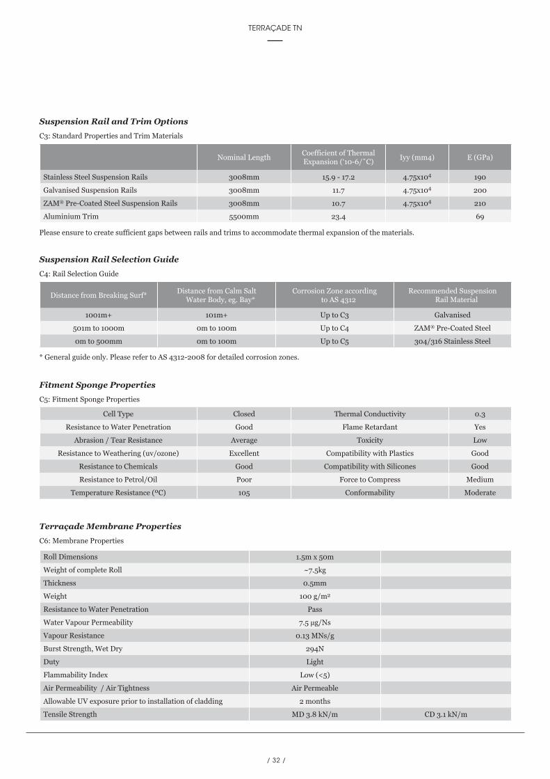
Suspension Rail and Trim OptionsC3: Standard Properties and Trim Materials
Suspension Rail Selection GuideC4: Rail Selection Guide
Fitment Sponge PropertiesC5: Fitment Sponge Properties
Terraçade Membrane PropertiesC6: Membrane Properties
Please ensure to create sufficient gaps between rails and trims to accommodate thermal expansion of the materials.
* General guide only. Please refer to AS 4312-2008 for detailed corrosion zones.
Nominal LengthCoefficient of Thermal Expansion (‘10-6/˚C)
Iyy (mm4) E (GPa)
Stainless Steel Suspension Rails 3008mm 15.9 - 17.2 4.75x10⁴ 190
Galvanised Suspension Rails 3008mm 11.7 4.75x10⁴ 200
ZAM® Pre-Coated Steel Suspension Rails 3008mm 10.7 4.75x10⁴ 210
Aluminium Trim 5500mm 23.4 69
Distance from Breaking Surf*Distance from Calm Salt
Water Body, eg. Bay*Corrosion Zone according
to AS 4312Recommended Suspension
Rail Material
1001m+ 101m+ Up to C3 Galvanised
501m to 1000m 0m to 100m Up to C4 ZAM® Pre-Coated Steel
0m to 500mm 0m to 100m Up to C5 304/316 Stainless Steel
Cell Type Closed Thermal Conductivity 0.3
Resistance to Water Penetration Good Flame Retardant Yes
Abrasion / Tear Resistance Average Toxicity Low
Resistance to Weathering (uv/ozone) Excellent Compatibility with Plastics Good
Resistance to Chemicals Good Compatibility with Silicones Good
Resistance to Petrol/Oil Poor Force to Compress Medium
Temperature Resistance (ºC) 105 Conformability Moderate
Roll Dimensions 1.5m x 50m
Weight of complete Roll ~7.5kg
Thickness 0.5mm
Weight 100 g/m2
Resistance to Water Penetration Pass
Water Vapour Permeability 7.5 μg/Ns
Vapour Resistance 0.13 MNs/g
Burst Strength, Wet Dry 294N
Duty Light
Flammability Index Low (<5)
Air Permeability / Air Tightness Air Permeable
Allowable UV exposure prior to installation of cladding 2 months
Tensile Strength MD 3.8 kN/m CD 3.1 kN/m
/ 33 /
fifth edition TECHNICAL MANUAL
TECHNICAL SPECIFICATIONS
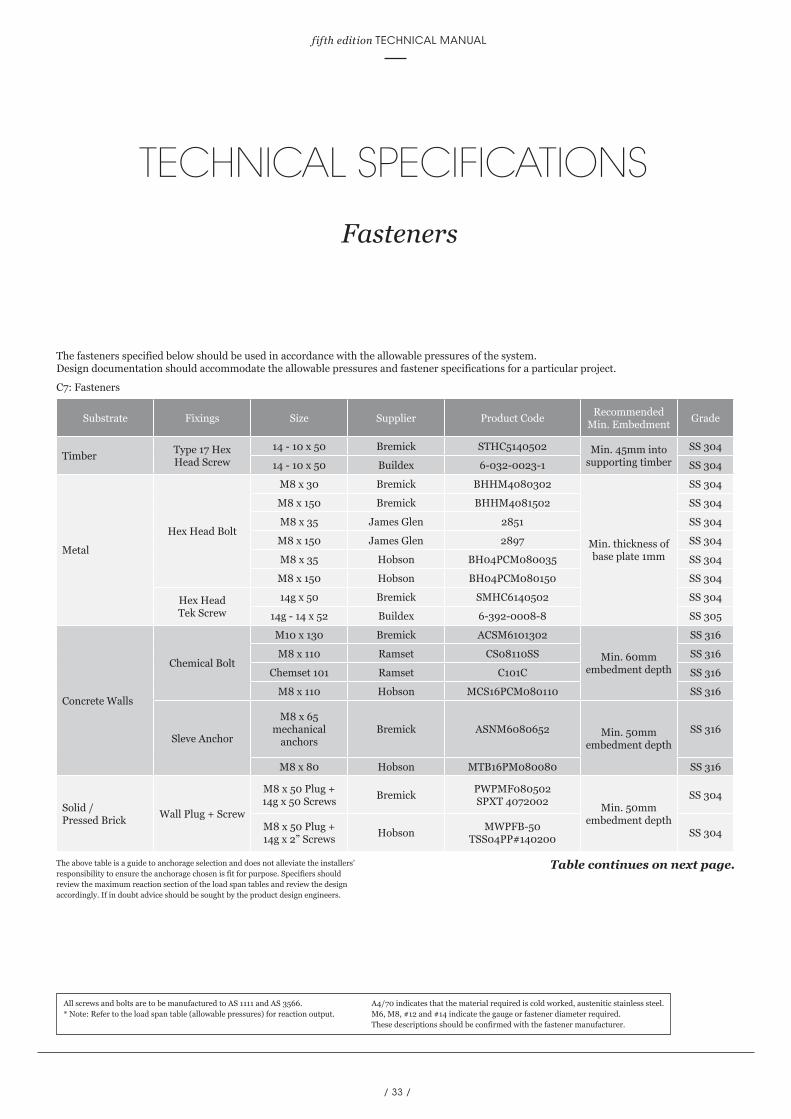
Fasteners
The fasteners specified below should be used in accordance with the allowable pressures of the system. Design documentation should accommodate the allowable pressures and fastener specifications for a particular project.
The above table is a guide to anchorage selection and does not alleviate the installers’ responsibility to ensure the anchorage chosen is fit for purpose. Specifiers should review the maximum reaction section of the load span tables and review the design accordingly. If in doubt advice should be sought by the product design engineers.
All screws and bolts are to be manufactured to AS 1111 and AS 3566.* Note: Refer to the load span table (allowable pressures) for reaction output.
A4/70 indicates that the material required is cold worked, austenitic stainless steel.M6, M8, #12 and #14 indicate the gauge or fastener diameter required.These descriptions should be confirmed with the fastener manufacturer.
Substrate Fixings Size Supplier Product CodeRecommended
Min. EmbedmentGrade
TimberType 17 Hex Head Screw
14 - 10 x 50 Bremick STHC5140502 Min. 45mm into supporting timber
SS 304
14 - 10 x 50 Buildex 6-032-0023-1 SS 304
Metal
Hex Head Bolt
M8 x 30 Bremick BHHM4080302
Min. thickness of base plate 1mm
SS 304
M8 x 150 Bremick BHHM4081502 SS 304
M8 x 35 James Glen 2851 SS 304
M8 x 150 James Glen 2897 SS 304
M8 x 35 Hobson BH04PCM080035 SS 304
M8 x 150 Hobson BH04PCM080150 SS 304
Hex Head Tek Screw
14g x 50 Bremick SMHC6140502 SS 304
14g - 14 x 52 Buildex 6-392-0008-8 SS 305
Concrete Walls
Chemical Bolt
M10 x 130 Bremick ACSM6101302
Min. 60mm embedment depth
SS 316
M8 x 110 Ramset CS08110SS SS 316
Chemset 101 Ramset C101C SS 316
M8 x 110 Hobson MCS16PCM080110 SS 316
Sleve Anchor
M8 x 65 mechanical
anchorsBremick ASNM6080652 Min. 50mm
embedment depth
SS 316
M8 x 80 Hobson MTB16PM080080 SS 316
Solid / Pressed Brick
Wall Plug + Screw
M8 x 50 Plug + 14g x 50 Screws
BremickPWPMF080502 SPXT 4072002
Min. 50mm embedment depth
SS 304
M8 x 50 Plug + 14g x 2” Screws
HobsonMWPFB-50
TSS04PP#140200SS 304
Table continues on next page.
C7: Fasteners
/ 34 /
TERRAÇADE TN
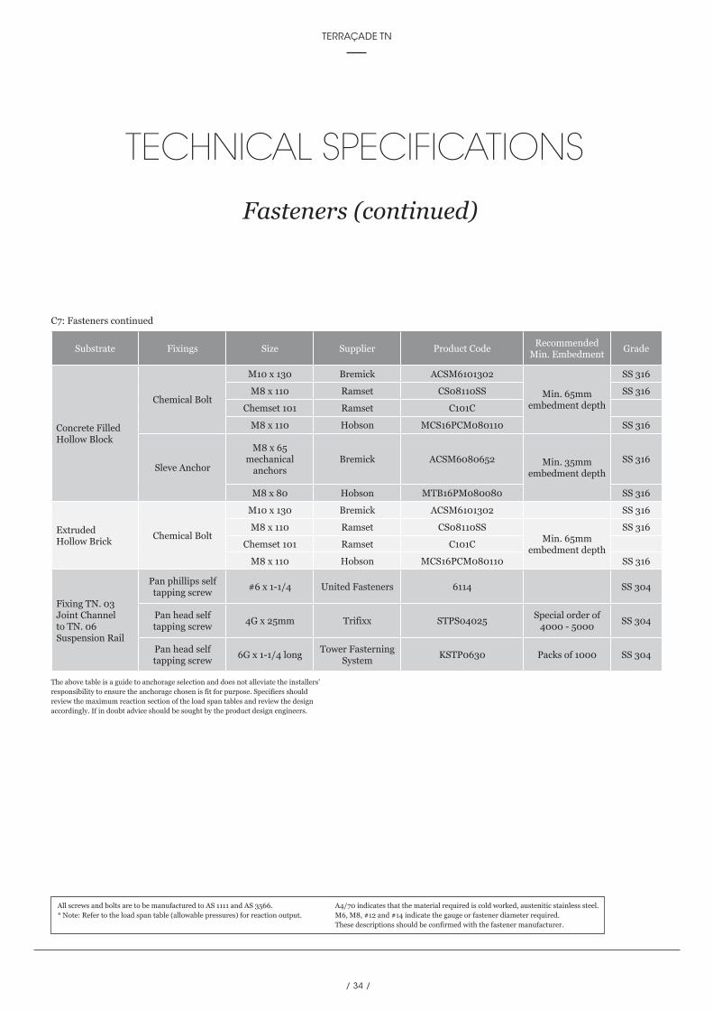
Substrate Fixings Size Supplier Product CodeRecommended
Min. EmbedmentGrade
Concrete Filled Hollow Block
Chemical Bolt
M10 x 130 Bremick ACSM6101302
Min. 65mm embedment depth
SS 316
M8 x 110 Ramset CS08110SS SS 316
Chemset 101 Ramset C101C
M8 x 110 Hobson MCS16PCM080110 SS 316
Sleve Anchor
M8 x 65 mechanical
anchorsBremick ACSM6080652 Min. 35mm
embedment depth
SS 316
M8 x 80 Hobson MTB16PM080080 SS 316
Extruded Hollow Brick
Chemical Bolt
M10 x 130 Bremick ACSM6101302 SS 316
M8 x 110 Ramset CS08110SSMin. 65mm
embedment depth
SS 316
Chemset 101 Ramset C101C
M8 x 110 Hobson MCS16PCM080110 SS 316
Fixing TN. 03 Joint Channel to TN. 06 Suspension Rail
Pan phillips self tapping screw
#6 x 1-1/4 United Fasteners 6114 SS 304
Pan head self tapping screw
4G x 25mm Trifixx STPS04025Special order of
4000 - 5000SS 304
Pan head self tapping screw
6G x 1-1/4 longTower Fasterning
SystemKSTP0630 Packs of 1000 SS 304
The above table is a guide to anchorage selection and does not alleviate the installers’ responsibility to ensure the anchorage chosen is fit for purpose. Specifiers should review the maximum reaction section of the load span tables and review the design accordingly. If in doubt advice should be sought by the product design engineers.
All screws and bolts are to be manufactured to AS 1111 and AS 3566.* Note: Refer to the load span table (allowable pressures) for reaction output.
A4/70 indicates that the material required is cold worked, austenitic stainless steel.M6, M8, #12 and #14 indicate the gauge or fastener diameter required.These descriptions should be confirmed with the fastener manufacturer.
TECHNICAL SPECIFICATIONS
Fasteners (continued)
C7: Fasteners continued
/ 35 /
fifth edition TECHNICAL MANUAL
TECHNICAL SPECIFICATIONS
System Performance
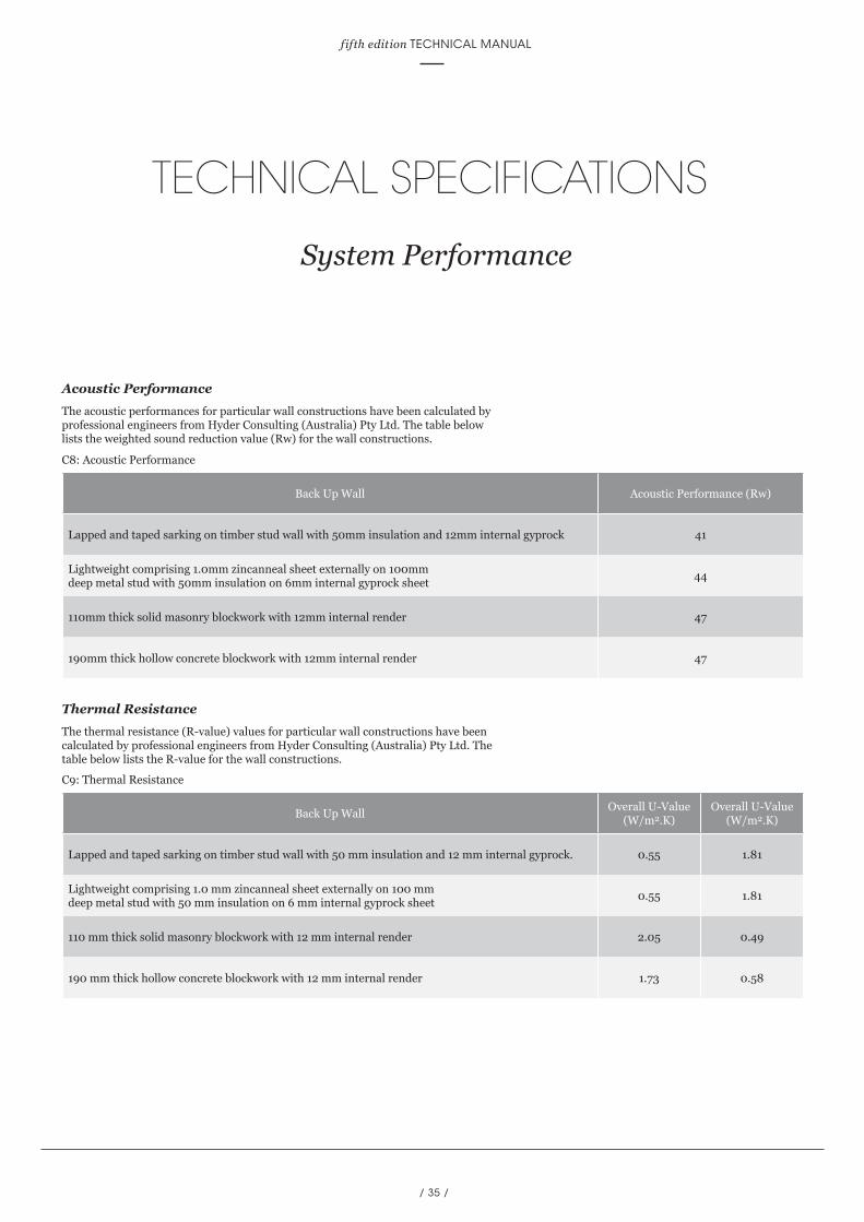
Acoustic PerformanceThe acoustic performances for particular wall constructions have been calculated by professional engineers from Hyder Consulting (Australia) Pty Ltd. The table below lists the weighted sound reduction value (Rw) for the wall constructions.
Thermal ResistanceThe thermal resistance (R-value) values for particular wall constructions have been calculated by professional engineers from Hyder Consulting (Australia) Pty Ltd. The table below lists the R-value for the wall constructions.
Back Up Wall Acoustic Performance (Rw)
Lapped and taped sarking on timber stud wall with 50mm insulation and 12mm internal gyprock 41
Lightweight comprising 1.0mm zincanneal sheet externally on 100mm deep metal stud with 50mm insulation on 6mm internal gyprock sheet
44
110mm thick solid masonry blockwork with 12mm internal render 47
190mm thick hollow concrete blockwork with 12mm internal render 47
Back Up WallOverall U-Value
(W/m2.K)Overall U-Value
(W/m2.K)
Lapped and taped sarking on timber stud wall with 50 mm insulation and 12 mm internal gyprock. 0.55 1.81
Lightweight comprising 1.0 mm zincanneal sheet externally on 100 mm deep metal stud with 50 mm insulation on 6 mm internal gyprock sheet
0.55 1.81
110 mm thick solid masonry blockwork with 12 mm internal render 2.05 0.49
190 mm thick hollow concrete blockwork with 12 mm internal render 1.73 0.58
C9: Thermal Resistance
C8: Acoustic Performance
/ 36 /
TERRAÇADE TN
INSTALLATION
2For the most up to date information on Terraçade products and the latest version
of this manual, please refer to our website; www.terracade.com.au
/ 36 /
COMPONENTS
5For the most up to date information on Terraçade products and the latest version
of this manual, please refer to our website; www.terracade.com.au
TERRAÇADE TN
/ 37 /
fifth edition TECHNICAL MANUAL
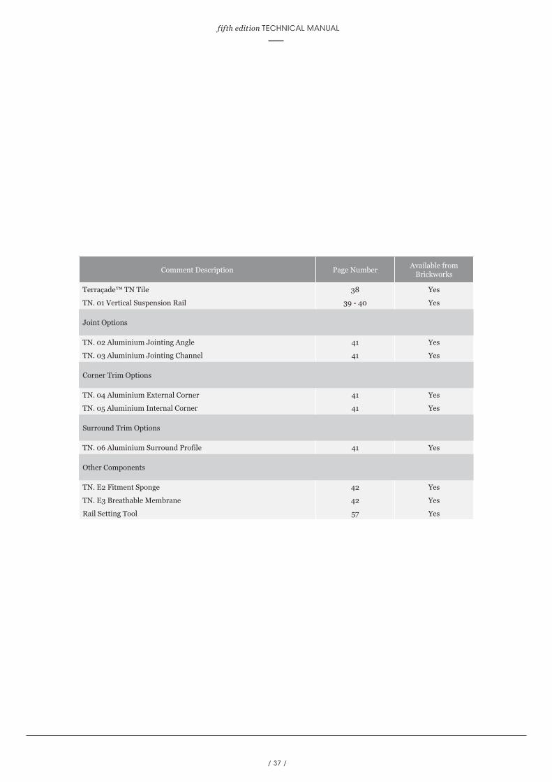
Comment Description Page NumberAvailable from
Brickworks
Terraçade™ TN Tile 38 Yes
TN. 01 Vertical Suspension Rail 39 - 40 Yes
Joint Options
TN. 02 Aluminium Jointing Angle 41 Yes
TN. 03 Aluminium Jointing Channel 41 Yes
Corner Trim Options
TN. 04 Aluminium External Corner 41 Yes
TN. 05 Aluminium Internal Corner 41 Yes
Surround Trim Options
TN. 06 Aluminium Surround Profile 41 Yes
Other Components
TN. E2 Fitment Sponge 42 Yes
TN. E3 Breathable Membrane 42 Yes
Rail Setting Tool 57 Yes
/ 38 /
TERRAÇADE TN
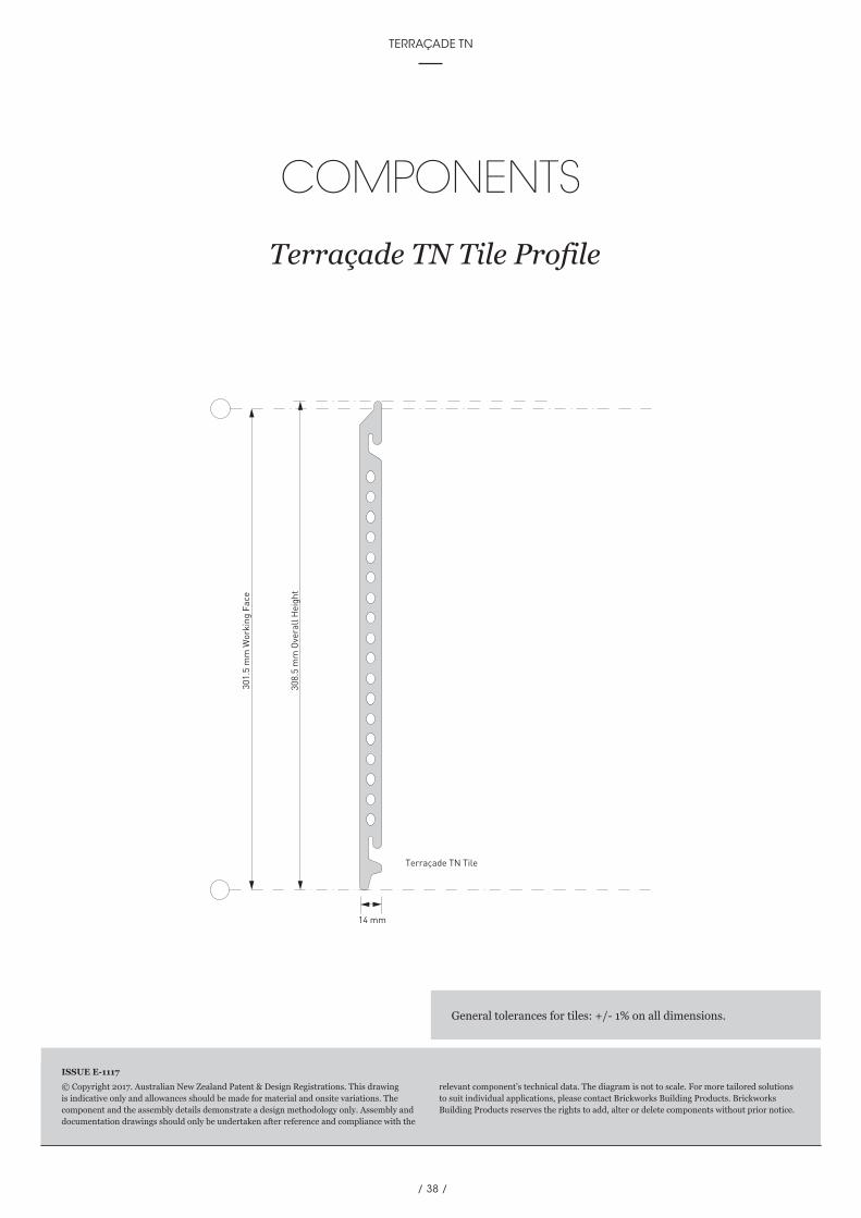
301.
5 m
m W
orki
ng F
ace
14 mm
Terraçade TN Tile
308.
5 m
m O
vera
ll H
eigh
t
COMPONENTS
Terraçade TN Tile Profile
© Copyright 2017. Australian New Zealand Patent & Design Registrations. This drawing is indicative only and allowances should be made for material and onsite variations. The component and the assembly details demonstrate a design methodology only. Assembly and documentation drawings should only be undertaken after reference and compliance with the
relevant component’s technical data. The diagram is not to scale. For more tailored solutions to suit individual applications, please contact Brickworks Building Products. Brickworks Building Products reserves the rights to add, alter or delete components without prior notice.
ISSUE E-1117
General tolerances for tiles: +/- 1% on all dimensions.
/ 39 /
fifth edition TECHNICAL MANUAL
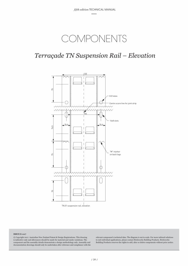
COMPONENTS
Terraçade TN Suspension Rail – Elevation75
76.5
24.4 24.4
70
130
104
75
16x8 slots
"M" markeron back legs
TN.01 suspension rail, elevation
8.0 holes
Centre score line for joint strip
© Copyright 2017. Australian New Zealand Patent & Design Registrations. This drawing is indicative only and allowances should be made for material and onsite variations. The component and the assembly details demonstrate a design methodology only. Assembly and documentation drawings should only be undertaken after reference and compliance with the
relevant component’s technical data. The diagram is not to scale. For more tailored solutions to suit individual applications, please contact Brickworks Building Products. Brickworks Building Products reserves the rights to add, alter or delete components without prior notice.
ISSUE E-1117

/ 40 /
TERRAÇADE TN
© Copyright 2017. Australian New Zealand Patent & Design Registrations. This drawing is indicative only and allowances should be made for material and onsite variations. The component and the assembly details demonstrate a design methodology only. Assembly and documentation drawings should only be undertaken after reference and compliance with the
relevant component’s technical data. The diagram is not to scale. For more tailored solutions to suit individual applications, please contact Brickworks Building Products. Brickworks Building Products reserves the rights to add, alter or delete components without prior notice.
ISSUE E-1117
COMPONENTS
Terraçade TN Suspension Rail – Plan
8124.5 24.5
1435
130
27
12.3
27
TN.01 suspension rail, plan
49
93° 93°

/ 41 /
fifth edition TECHNICAL MANUAL
COMPONENTS
Surround Trim, Corner Trim and Joint Options
© Copyright 2017. Australian New Zealand Patent & Design Registrations. This drawing is indicative only and allowances should be made for material and onsite variations. The component and the assembly details demonstrate a design methodology only. Assembly and documentation drawings should only be undertaken after reference and compliance with the
relevant component’s technical data. The diagram is not to scale. For more tailored solutions to suit individual applications, please contact Brickworks Building Products. Brickworks Building Products reserves the rights to add, alter or delete components without prior notice.
ISSUE E-1117
67
20.0
TN.06 aluminium surround profile
60.3
21.4 5.0
12.0
1.6
20.0
TN. 02 Aluminium Joint Angle
TN. 04 Aluminium External Corner
10
20
TN.03 aluminium jointing channel
22.5
110.5
22.5
19.9
13.5 30
TN.05 aluminium internal corner
/ 42 /
TERRAÇADE TN
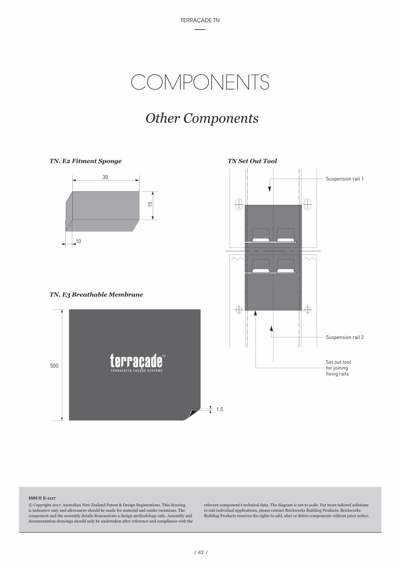
COMPONENTS
Other Components
© Copyright 2017. Australian New Zealand Patent & Design Registrations. This drawing is indicative only and allowances should be made for material and onsite variations. The component and the assembly details demonstrate a design methodology only. Assembly and documentation drawings should only be undertaken after reference and compliance with the
relevant component’s technical data. The diagram is not to scale. For more tailored solutions to suit individual applications, please contact Brickworks Building Products. Brickworks Building Products reserves the rights to add, alter or delete components without prior notice.
ISSUE E-1117
15
30
TN.E2 fitment sponge
TN.E3 Breathable membrane
10
1.5
1500
15
30
TN.E2 fitment sponge
TN.E3 Breathable membrane
10
1.5
1500
74
Suspension rail 2
Suspension rail 1
Suspension rail 2
Suspension rail 1
Set out toolfor joiningfixing rails
TN. E2 Fitment Sponge TN Set Out Tool
TN. E3 Breathable Membrane

/ 43 /
fifth edition TECHNICAL MANUAL

/ 44 /
TERRAÇADE TN
INSTALLATION
2For the most up to date information on Terraçade products and the latest version
of this manual, please refer to our website; www.terracade.com.au
/ 44 /
SYSTEM DESIGN
6For the most up to date information on Terraçade products and the latest version
of this manual, please refer to our website; www.terracade.com.au
TERRAÇADE TN
/ 45 /
fifth edition TECHNICAL MANUAL
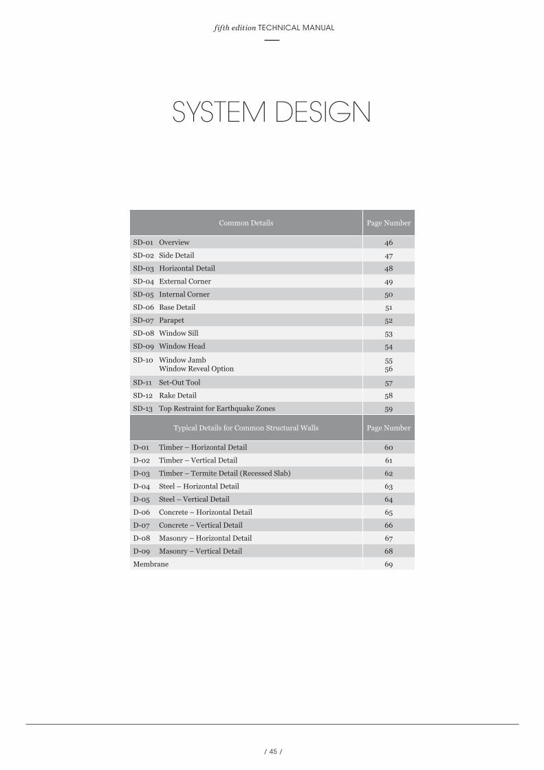
SYSTEM DESIGN
Common Details Page Number
SD-01 Overview 46
SD-02 Side Detail 47
SD-03 Horizontal Detail 48
SD-04 External Corner 49
SD-05 Internal Corner 50
SD-06 Base Detail 51
SD-07 Parapet 52
SD-08 Window Sill 53
SD-09 Window Head 54
SD-10 Window Jamb Window Reveal Option
55 56
SD-11 Set-Out Tool 57
SD-12 Rake Detail 58
SD-13 Top Restraint for Earthquake Zones 59
Typical Details for Common Structural Walls Page Number
D-01 Timber – Horizontal Detail 60
D-02 Timber – Vertical Detail 61
D-03 Timber – Termite Detail (Recessed Slab) 62
D-04 Steel – Horizontal Detail 63
D-05 Steel – Vertical Detail 64
D-06 Concrete – Horizontal Detail 65
D-07 Concrete – Vertical Detail 66
D-08 Masonry – Horizontal Detail 67
D-09 Masonry – Vertical Detail 68
Membrane 69

/ 46 /
TERRAÇADE TN
SYSTEM DESIGN
Overview – SD 01
© Copyright 2017. Australian New Zealand Patent & Design Registrations. This drawing is indicative only and allowances should be made for material and onsite variations. The component and the assembly details demonstrate a design methodology only. Assembly and documentation drawings should only be undertaken after reference and compliance with the
relevant component’s technical data. The diagram is not to scale. For more tailored solutions to suit individual applications, please contact Brickworks Building Products. Brickworks Building Products reserves the rights to add, alter or delete components without prior notice.
ISSUE E-1117
600600600600600600600600
3008
1400
6001,600 600400500
500
500
400
5
SD–06
SD–05
SD–04
SD–10 SD–03
200
300
300
300
300
300
300
300
300
300
300
300
300
300
300
300
200
300
1400
300
300
300
300
300
300
200
200
200
D-15
SD–04
SD–07
SD–11 SD–02

/ 47 /
fifth edition TECHNICAL MANUAL
SYSTEM DESIGN
Side Detail – SD 02
© Copyright 2017. Australian New Zealand Patent & Design Registrations. This drawing is indicative only and allowances should be made for material and onsite variations. The component and the assembly details demonstrate a design methodology only. Assembly and documentation drawings should only be undertaken after reference and compliance with the
relevant component’s technical data. The diagram is not to scale. For more tailored solutions to suit individual applications, please contact Brickworks Building Products. Brickworks Building Products reserves the rights to add, alter or delete components without prior notice.
ISSUE E-1117
Handy Tip• Fitment sponges should be fitted immediately prior
to installation of tiles.
47
3520.9
55.9
Mechanical fixing(refer to fastener table)
Structural wall
Terraçade TNsuspension rail
Terraçade TN tile
Fitment sponge

/ 48 /
TERRAÇADE TN
© Copyright 2017. Australian New Zealand Patent & Design Registrations. This drawing is indicative only and allowances should be made for material and onsite variations. The component and the assembly details demonstrate a design methodology only. Assembly and documentation drawings should only be undertaken after reference and compliance with the
relevant component’s technical data. The diagram is not to scale. For more tailored solutions to suit individual applications, please contact Brickworks Building Products. Brickworks Building Products reserves the rights to add, alter or delete components without prior notice.
ISSUE E-1117
SYSTEM DESIGN
Horizontal Detail – SD 03
104
130
Mechanical fixing (refer to fastener table)
Terraçade TN suspension rail
Terraçade TN tile
Tile joint is eitherseparated byTN. 06 Joint Angle orTN. 03 Joint Chanel

/ 49 /
fifth edition TECHNICAL MANUAL
SYSTEM DESIGN
External Corner – SD 04
50 (min)
50 (m
in)
35 20.9
37.1
37.1
TN 04 Aluminium external corner
Structural wall
Terraçade TN suspension rail
Terraçade TNsuspension rail
Mechanical fixing(refer to fastener table)
Fixings staggeredto avoid clash
Aluminium angleattached to fixing railsupplied (by others)
Terraçade TN tile
© Copyright 2017. Australian New Zealand Patent & Design Registrations. This drawing is indicative only and allowances should be made for material and onsite variations. The component and the assembly details demonstrate a design methodology only. Assembly and documentation drawings should only be undertaken after reference and compliance with the
relevant component’s technical data. The diagram is not to scale. For more tailored solutions to suit individual applications, please contact Brickworks Building Products. Brickworks Building Products reserves the rights to add, alter or delete components without prior notice.
ISSUE E-1117
/ 50 /
TERRAÇADE TN
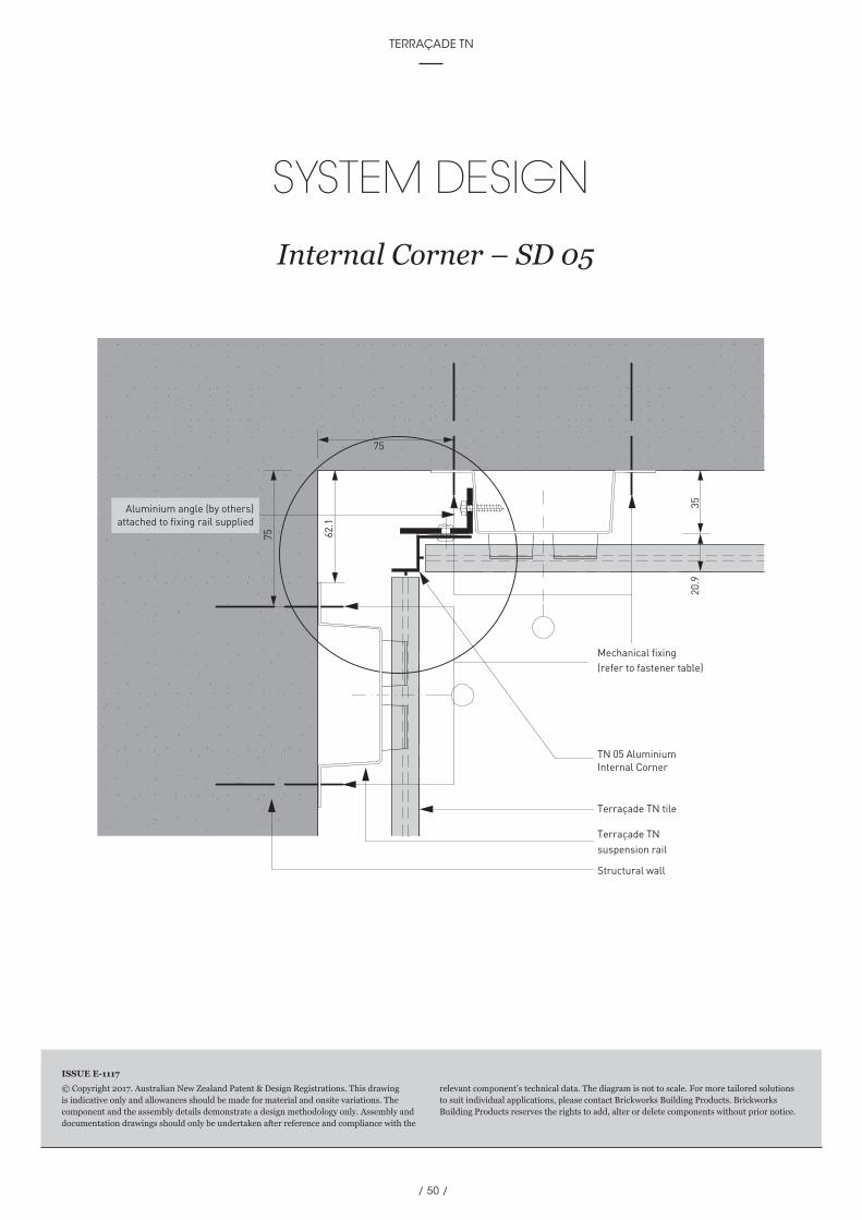
SYSTEM DESIGN
Internal Corner – SD 05
75
TN 05 AluminiumInternal Corner
Mechanical fixing(refer to fastener table)
Structural wall
Terraçade TNsuspension rail
Terraçade TN tile
75 62.1
3520
.9
Aluminium angle (by others)attached to fixing rail supplied
© Copyright 2017. Australian New Zealand Patent & Design Registrations. This drawing is indicative only and allowances should be made for material and onsite variations. The component and the assembly details demonstrate a design methodology only. Assembly and documentation drawings should only be undertaken after reference and compliance with the
relevant component’s technical data. The diagram is not to scale. For more tailored solutions to suit individual applications, please contact Brickworks Building Products. Brickworks Building Products reserves the rights to add, alter or delete components without prior notice.
ISSUE E-1117

/ 51 /
fifth edition TECHNICAL MANUAL
SYSTEM DESIGN
Base Detail – SD 06
© Copyright 2017. Australian New Zealand Patent & Design Registrations. This drawing is indicative only and allowances should be made for material and onsite variations. The component and the assembly details demonstrate a design methodology only. Assembly and documentation drawings should only be undertaken after reference and compliance with the
relevant component’s technical data. The diagram is not to scale. For more tailored solutions to suit individual applications, please contact Brickworks Building Products. Brickworks Building Products reserves the rights to add, alter or delete components without prior notice.
ISSUE E-1117
TN.06 Aluminium surroundprofile (drainage slots cut as
required by the installers)
01
64
Whole Tile
TN.06 Aluminium surroundprofile (drainage slots cut as
required by the installers)
01
64
Cut Tile
/ 52 /
TERRAÇADE TN
SYSTEM DESIGN
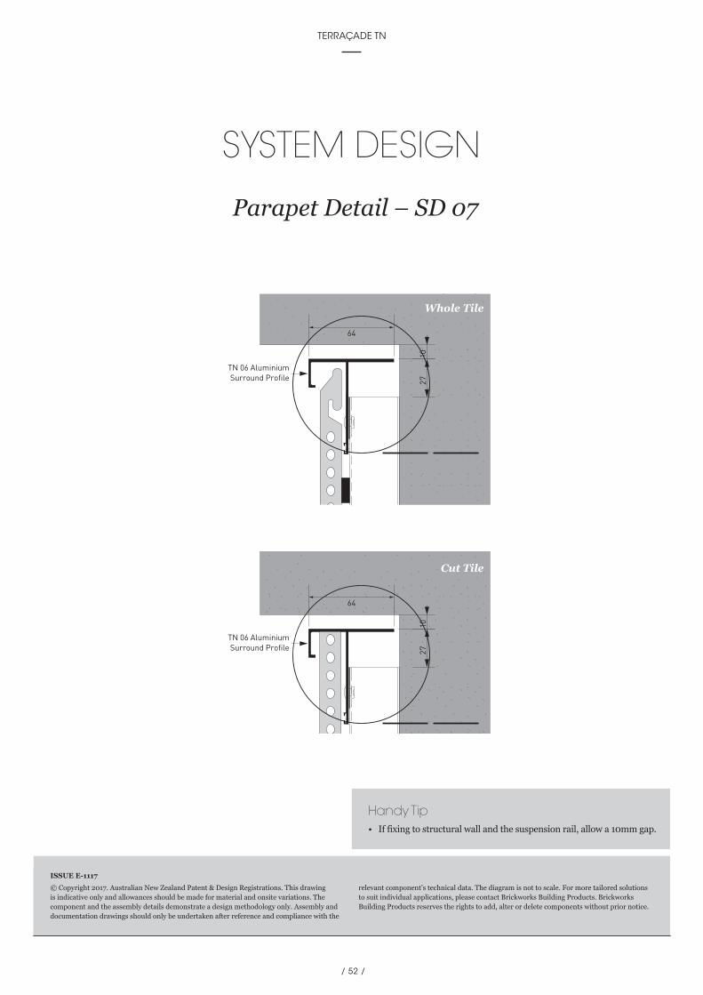
Parapet Detail – SD 07
© Copyright 2017. Australian New Zealand Patent & Design Registrations. This drawing is indicative only and allowances should be made for material and onsite variations. The component and the assembly details demonstrate a design methodology only. Assembly and documentation drawings should only be undertaken after reference and compliance with the
relevant component’s technical data. The diagram is not to scale. For more tailored solutions to suit individual applications, please contact Brickworks Building Products. Brickworks Building Products reserves the rights to add, alter or delete components without prior notice.
ISSUE E-1117
0172
TN 06 AluminiumSurround Profile
64
0172
TN 06 AluminiumSurround Profile
64
Handy Tip• If fixing to structural wall and the suspension rail, allow a 10mm gap.
Whole Tile
Cut Tile
/ 53 /
fifth edition TECHNICAL MANUAL
SYSTEM DESIGN
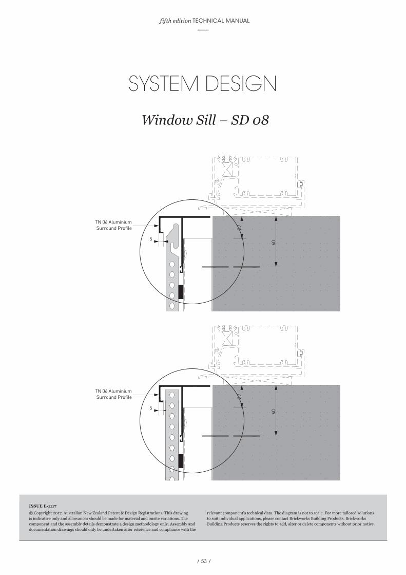
Window Sill – SD 08
© Copyright 2017. Australian New Zealand Patent & Design Registrations. This drawing is indicative only and allowances should be made for material and onsite variations. The component and the assembly details demonstrate a design methodology only. Assembly and documentation drawings should only be undertaken after reference and compliance with the
relevant component’s technical data. The diagram is not to scale. For more tailored solutions to suit individual applications, please contact Brickworks Building Products. Brickworks Building Products reserves the rights to add, alter or delete components without prior notice.
ISSUE E-1117
5 06
72
TN 06 AluminiumSurround Profile
5 06
72
TN 06 AluminiumSurround Profile

/ 54 /
TERRAÇADE TN
SYSTEM DESIGN
Window Head – SD 09
60
27TN. 06 AluminiumSurround Profile
(drainage slots cut asrequired by the installers)
Whole Tile
60
27TN. 06 AluminiumSurround Profile
(drainage slots cut asrequired by the installers)
Cut Tile
© Copyright 2017. Australian New Zealand Patent & Design Registrations. This drawing is indicative only and allowances should be made for material and onsite variations. The component and the assembly details demonstrate a design methodology only. Assembly and documentation drawings should only be undertaken after reference and compliance with the
relevant component’s technical data. The diagram is not to scale. For more tailored solutions to suit individual applications, please contact Brickworks Building Products. Brickworks Building Products reserves the rights to add, alter or delete components without prior notice.
ISSUE E-1117

/ 55 /
fifth edition TECHNICAL MANUAL
SYSTEM DESIGN
Window Jamb – SD 10
70 98
123.857.1
Aluminium angle attachedto fixing rail supplied (by others)
TN 06 AluminiumSurround Profile
© Copyright 2017. Australian New Zealand Patent & Design Registrations. This drawing is indicative only and allowances should be made for material and onsite variations. The component and the assembly details demonstrate a design methodology only. Assembly and documentation drawings should only be undertaken after reference and compliance with the
relevant component’s technical data. The diagram is not to scale. For more tailored solutions to suit individual applications, please contact Brickworks Building Products. Brickworks Building Products reserves the rights to add, alter or delete components without prior notice.
ISSUE E-1117

/ 56 /
TERRAÇADE TN
SYSTEM DESIGN
Window Jamb – SD 10 Window Reveal Option
Timber frame
Terraçade TNsuspension rail
Damp course flashing
Timber reveal/jamb
Aluminium window profile (by others)
Timber reveal/jamb
Window Glazing
Gyprock/Plasterboard
Terraçade TN tile
© Copyright 2017. Australian New Zealand Patent & Design Registrations. This drawing is indicative only and allowances should be made for material and onsite variations. The component and the assembly details demonstrate a design methodology only. Assembly and documentation drawings should only be undertaken after reference and compliance with the
relevant component’s technical data. The diagram is not to scale. For more tailored solutions to suit individual applications, please contact Brickworks Building Products. Brickworks Building Products reserves the rights to add, alter or delete components without prior notice.
ISSUE E-1117
/ 57 /
fifth edition TECHNICAL MANUAL
SYSTEM DESIGN
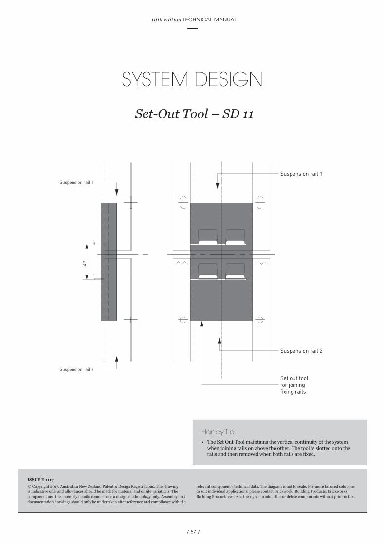
Set-Out Tool – SD 11
© Copyright 2017. Australian New Zealand Patent & Design Registrations. This drawing is indicative only and allowances should be made for material and onsite variations. The component and the assembly details demonstrate a design methodology only. Assembly and documentation drawings should only be undertaken after reference and compliance with the
relevant component’s technical data. The diagram is not to scale. For more tailored solutions to suit individual applications, please contact Brickworks Building Products. Brickworks Building Products reserves the rights to add, alter or delete components without prior notice.
ISSUE E-1117
74
Suspension rail 2
Suspension rail 1
Suspension rail 2
Suspension rail 1
Set out toolfor joiningfixing rails
Handy Tip• The Set Out Tool maintains the vertical continuity of the system
when joining rails on above the other. The tool is slotted onto the rails and then removed when both rails are fixed.

/ 58 /
TERRAÇADE TN
SYSTEM DESIGN
Rake Detail – SD 12
© Copyright 2017. Australian New Zealand Patent & Design Registrations. This drawing is indicative only and allowances should be made for material and onsite variations. The component and the assembly details demonstrate a design methodology only. Assembly and documentation drawings should only be undertaken after reference and compliance with the
relevant component’s technical data. The diagram is not to scale. For more tailored solutions to suit individual applications, please contact Brickworks Building Products. Brickworks Building Products reserves the rights to add, alter or delete components without prior notice.
ISSUE E-1117

/ 59 /
fifth edition TECHNICAL MANUAL
© Copyright 2017. Australian New Zealand Patent & Design Registrations. This drawing is indicative only and allowances should be made for material and onsite variations. The component and the assembly details demonstrate a design methodology only. Assembly and documentation drawings should only be undertaken after reference and compliance with the
relevant component’s technical data. The diagram is not to scale. For more tailored solutions to suit individual applications, please contact Brickworks Building Products. Brickworks Building Products reserves the rights to add, alter or delete components without prior notice.
ISSUE E-1117
SYSTEM DESIGN
Top Restraint for Earthquake Zones – SD 13
TN 06 AluminiumSurround Profile
Fitment Sponge
Structural wall
Terraçade TNsuspension rail
Terraçade TN tile
Flexible Sealant
Fitment sponge
50 x 25 x 1.6mm aluminiumangle or similar (by others)

/ 60 /
TERRAÇADE TN
SYSTEM DESIGN
Horizontal Detail – D-01 Timber
© Copyright 2017. Australian New Zealand Patent & Design Registrations. This drawing is indicative only and allowances should be made for material and onsite variations. The component and the assembly details demonstrate a design methodology only. Assembly and documentation drawings should only be undertaken after reference and compliance with the
relevant component’s technical data. The diagram is not to scale. For more tailored solutions to suit individual applications, please contact Brickworks Building Products. Brickworks Building Products reserves the rights to add, alter or delete components without prior notice.
ISSUE E-1117
12
81
20.9
35
130
45 m
inin
to ti
mbe
r
104
Timber wall
Breathable membrane
Terraçade TN suspension rail
TN. 06 Joint Angle orTN. 03 Joint Channel
Terraçade TN tile
Handy Tip• Spray or brush the central section of the coastal version suspension
rail face (between the hanging tabs) matt black to reduce reflection through any gaps.

/ 61 /
fifth edition TECHNICAL MANUAL
SYSTEM DESIGN
Vertical Detail – D-02 Timber
© Copyright 2017. Australian New Zealand Patent & Design Registrations. This drawing is indicative only and allowances should be made for material and onsite variations. The component and the assembly details demonstrate a design methodology only. Assembly and documentation drawings should only be undertaken after reference and compliance with the
relevant component’s technical data. The diagram is not to scale. For more tailored solutions to suit individual applications, please contact Brickworks Building Products. Brickworks Building Products reserves the rights to add, alter or delete components without prior notice.
ISSUE E-1117
75
45mm into timber
55.9
Breathable membrane
Terraçade TNsuspension rail
Timber wall
Tek Screw Type M mechanical fixing as specified in fastener table
Terraçade TN tile
Fitment sponge

/ 62 /
TERRAÇADE TN
SYSTEM DESIGN
Recessed Slab – D-03 Termite Detail
© Copyright 2017. Australian New Zealand Patent & Design Registrations. This drawing is indicative only and allowances should be made for material and onsite variations. The component and the assembly details demonstrate a design methodology only. Assembly and documentation drawings should only be undertaken after reference and compliance with the
relevant component’s technical data. The diagram is not to scale. For more tailored solutions to suit individual applications, please contact Brickworks Building Products. Brickworks Building Products reserves the rights to add, alter or delete components without prior notice.
ISSUE E-1117
TN 06 AluminiumSurround Profile
Flashing
Additional anglefor termite mesh
Flashing

/ 63 /
fifth edition TECHNICAL MANUAL
SYSTEM DESIGN
Horizontal Detail – D-04 Stainless Steel
130
20.9
35
104
Breathable membrane
M6 A4/70 bolts(as specified inthe fastener table)to front of 'C' purlin
Steel wall
Local capacity of 'C' purlinto be confirmed bypurlin manufacturerprior to construction
Terraçade TN suspension rail
Terraçade TN tile
TN. 06 Joint Angle orTN. 03 Joint Channel
© Copyright 2017. Australian New Zealand Patent & Design Registrations. This drawing is indicative only and allowances should be made for material and onsite variations. The component and the assembly details demonstrate a design methodology only. Assembly and documentation drawings should only be undertaken after reference and compliance with the
relevant component’s technical data. The diagram is not to scale. For more tailored solutions to suit individual applications, please contact Brickworks Building Products. Brickworks Building Products reserves the rights to add, alter or delete components without prior notice.
ISSUE E-1117
Handy Tip• Spray or brush the central section of the coastal version suspension
rail face (between the hanging tabs) matt black to reduce reflection through any gaps.

/ 64 /
TERRAÇADE TN
SYSTEM DESIGN
Vertical Detail – D-05 Steel
75
60.9
Breathable membrane
M6 A4/70 bolts(as specified in
the fastener table)to front of 'C' purlin
Steel wall
Local capacity of 'C' purlinto purlin to be confirmed by
purlin manufacturerprior to construction
Terraçade TNsuspension rail
Terraçade TN tile
Fitment sponge
© Copyright 2017. Australian New Zealand Patent & Design Registrations. This drawing is indicative only and allowances should be made for material and onsite variations. The component and the assembly details demonstrate a design methodology only. Assembly and documentation drawings should only be undertaken after reference and compliance with the
relevant component’s technical data. The diagram is not to scale. For more tailored solutions to suit individual applications, please contact Brickworks Building Products. Brickworks Building Products reserves the rights to add, alter or delete components without prior notice.
ISSUE E-1117

/ 65 /
fifth edition TECHNICAL MANUAL
SYSTEM DESIGN
Horizontal Detail – D-06 Concrete
20.9
35
130
104
Concrete wall
M6 mechanicalanchors as specified in thefastener table
Terraçade TN suspension rail
TN. 06 Joint Angle orTN. 03 Joint Channel
Terraçade TN tile
55 m
inem
bedm
ent
© Copyright 2017. Australian New Zealand Patent & Design Registrations. This drawing is indicative only and allowances should be made for material and onsite variations. The component and the assembly details demonstrate a design methodology only. Assembly and documentation drawings should only be undertaken after reference and compliance with the
relevant component’s technical data. The diagram is not to scale. For more tailored solutions to suit individual applications, please contact Brickworks Building Products. Brickworks Building Products reserves the rights to add, alter or delete components without prior notice.
ISSUE E-1117
Handy Tip• Spray or brush the central section of the coastal version suspension
rail face (between the hanging tabs) matt black to reduce reflection through any gaps.

/ 66 /
TERRAÇADE TN
SYSTEM DESIGN
Vertical Detail – D-07 Concrete
© Copyright 2017. Australian New Zealand Patent & Design Registrations. This drawing is indicative only and allowances should be made for material and onsite variations. The component and the assembly details demonstrate a design methodology only. Assembly and documentation drawings should only be undertaken after reference and compliance with the
relevant component’s technical data. The diagram is not to scale. For more tailored solutions to suit individual applications, please contact Brickworks Building Products. Brickworks Building Products reserves the rights to add, alter or delete components without prior notice.
ISSUE E-1117
75
55 minembedment
55.9
Concrete wall
M6 mechanicalanchors as
specified in thefastener table
Terraçade TNsuspension rail
Terraçade TN tile
Fitment sponge

/ 67 /
fifth edition TECHNICAL MANUAL
SYSTEM DESIGN
Horizontal Detail – D-08 Masonry
© Copyright 2017. Australian New Zealand Patent & Design Registrations. This drawing is indicative only and allowances should be made for material and onsite variations. The component and the assembly details demonstrate a design methodology only. Assembly and documentation drawings should only be undertaken after reference and compliance with the
relevant component’s technical data. The diagram is not to scale. For more tailored solutions to suit individual applications, please contact Brickworks Building Products. Brickworks Building Products reserves the rights to add, alter or delete components without prior notice.
ISSUE E-1117
130
20.9
35
104
Terraçade TN suspension rail
Solid masonry wall(for other masonrysubstrates see fastener table)
#12 A4/70 screwsas specified inthe fastener table
load rated plasticplug anchors(refer to allowablepressure tables)
TN. 06 Joint Angle orTN. 03 Joint Channel
Terraçade TN tile
60 m
inim
um
Handy Tip• Spray or brush the central section of the coastal version suspension
rail face (between the hanging tabs) matt black to reduce reflection through any gaps.

/ 68 /
TERRAÇADE TN
© Copyright 2017. Australian New Zealand Patent & Design Registrations. This drawing is indicative only and allowances should be made for material and onsite variations. The component and the assembly details demonstrate a design methodology only. Assembly and documentation drawings should only be undertaken after reference and compliance with the
relevant component’s technical data. The diagram is not to scale. For more tailored solutions to suit individual applications, please contact Brickworks Building Products. Brickworks Building Products reserves the rights to add, alter or delete components without prior notice.
ISSUE E-1117
SYSTEM DESIGN
Vertical Detail – D-09 Masonry
60 min
55.9
#12 A4/70 screwsas specified in
the fastener table
Terraçade TNsuspension rail
Solid masonry wall(for other masonry
substrates seefastener table)
Load rated plasticplug anchors
(refer to allowablepressure tables)
Terraçade TN tile
Fitment sponge

/ 69 /
fifth edition TECHNICAL MANUAL
SYSTEM DESIGN
Membrane
© Copyright 2017. Australian New Zealand Patent & Design Registrations. This drawing is indicative only and allowances should be made for material and onsite variations. The component and the assembly details demonstrate a design methodology only. Assembly and documentation drawings should only be undertaken after reference and compliance with the
relevant component’s technical data. The diagram is not to scale. For more tailored solutions to suit individual applications, please contact Brickworks Building Products. Brickworks Building Products reserves the rights to add, alter or delete components without prior notice.
ISSUE E-1117
Membrane tape to tapeover the corner of thesarking and timber stud.
Fold Membrane in to coverrough opening sill
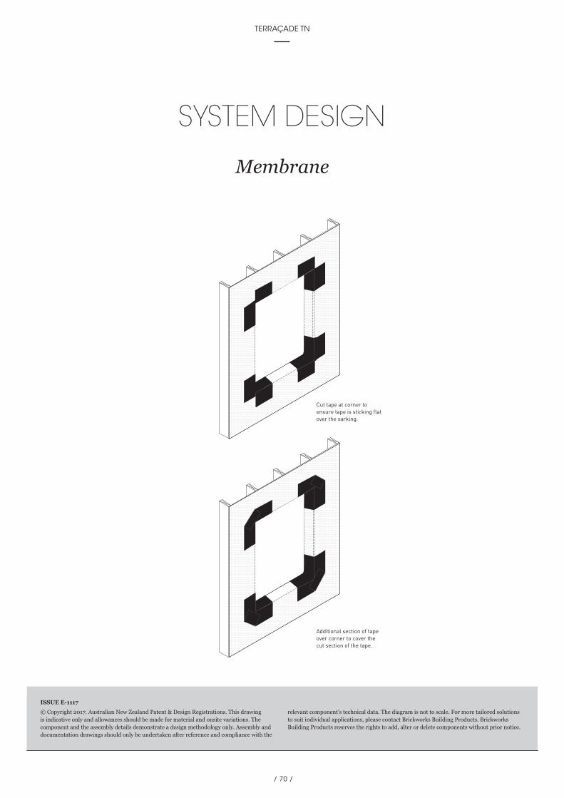
/ 70 /
TERRAÇADE TN
© Copyright 2017. Australian New Zealand Patent & Design Registrations. This drawing is indicative only and allowances should be made for material and onsite variations. The component and the assembly details demonstrate a design methodology only. Assembly and documentation drawings should only be undertaken after reference and compliance with the
relevant component’s technical data. The diagram is not to scale. For more tailored solutions to suit individual applications, please contact Brickworks Building Products. Brickworks Building Products reserves the rights to add, alter or delete components without prior notice.
ISSUE E-1117
SYSTEM DESIGN
Membrane
Additional section of tapeover corner to cover thecut section of the tape.
Cut tape at corner toensure tape is sticking flatover the sarking.

/ 71 /
fifth edition TECHNICAL MANUAL
MAINTENANCE GUIDE
For Terraçade Facade System Components
1. System InspectionIt is recommended that the Terraçade façade system be inspected at regular intervals to ensure the integrity of the system. The inspection interval will vary according to the sub-frame and trim components utilised in the system. Below is a summary of cleaning and maintenance information that can be accessed at the Terraçade website.
2. CleaningTerraçade tiles are a natural terracotta product and are therefore virtually maintenance free. If you wish to remove any dirt or pollution grime that has built up over time, simply lightly hose or sponge down the tiles with water.
The tiles should be washed down during installation using a sponge with water and a neutral pH cleaner and then rinsed off with clean water. For ongoing maintenance the tiles may be hosed or sponged to remove dust and the build-up of dirt. Normally, cleaning the tiles will be as easy as letting the rain do the work for you.
3. Aluminium Trimsa. Care & Maintenance Instructions:
A simple regular clean will minimise the effects of weathering and will remove dirt, grime and other build-up detrimental to all powder coatings.
b. Recommended cleaning method: Just a gentle clean with a soft brush and mild detergent, followed by a fresh water rinse, will maintain the long-term performance of your powder coated products. In rural or normal urban environments cleaning should occur every 12 months. In areas of high pollution, such as industrial areas, geothermal areas or coastal environments, cleaning should occur every three months. In particularly hazardous locations, such as beachfronts, severe marine environments or areas of high industrial pollution, cleaning should be increased to monthly.
c. Recommended cleaning products: To protect the surface of your powder coated products, do not use strong solvents, abrasive cleaning products or those products that are recommended for thinning various types of paints. If you need to remove splashed paint, sealants or mastics from your powder coated products, you can use white spirits. When using white spirits, cleaning should be carried out in shade and during cooler temperatures using a soft cloth and gentle wiping only. It is also recommended that, prior to use, a small non-visible area of your powder coated products be tested to ensure that no visual colour change or damage will occur, particularly with bright and deep colours.
4. Sealing TilesTerraçade tiles have a hard wearing surface that is resistant to most normal staining agents. In particularly difficult environments, for instance high traffic city areas, Terraçade may be exposed to graffiti vandalism or build up of carbon dirt from passing motor vehicle traffic. A high quality impregnating (penetrating) sealer can be used to make the surface easier to clean and prevent permanent staining as much as possible.
5. Replacing Individual TilesIt is difficult to remove individual tiles from a wall as it requires ‘shuffling’ of immediately adjacent tiles. It may be more practical to break the damaged tile with a rubber mallet so that it can be removed piece by piece. Care must be taken if this option is used as falling or sharp pieces of tiles may cause injuries.
To place a new tile into position, insert the top edge of the tile beneath the bottom edge of the tile above. Shuffle the tile above up slightly, ensuring that is restrained from falling by an assistant. Capture the tile on the top hook first and then the bottom hook. Check that the tile and the tiles above are fully engaged by visual and manual checks.

QUALITY GUARANTEE Brickworks Building Products continued commitment to quality and innovation ensures that Terraçade TN will remain the benchmark for excellence for many years to come. Our tradition, experience and financial strength have
made Brickworks Building Products the first choice for many architects, builders and designers.
Terraçade TN has a warranty of 20 years on the system and a 100 year warranty on colour fastness and durability, as per Terraçade Warranty for Terraçade. Contact Brickworks Building Products to have an architectural consultant
visit you with samples and technical information, or to discuss your next project.
Please note: Photographs should be considered indicative of colour and texture only. Variations in colour and shade are inherent in all clay fired products. All Terraçade tiles and accessories should
be ordered at the same time to avoid the possibility of batch to batch variations. No responsibility will be accepted for colour selection, matching, blending and any other physical or colour related defects once the
tiles have been incorporated into any construction. Terraçade™ and Terraçade TN™ are registered trademarks of the Brickworks Building Products or its wholly owned subsidiaries. ACN 119 059 513
Australian and New Zealand Patent & Australian and New Zealand Design Registrations. © 2017 All rights reserved Brickworks Building Products. Whole or partial reproduction of
this publication without Brickworks Building Products authorisation infringes reserved right; any utilisation must be previously requested.
a member of proud supporters
a member of proud supporters
a member of proud supporters
www.terracade.com.au 1800 001 013
Brown Ink Design | BW7928