TMT.OPT.PRE.07.061.REL01 HPS-280001-0105 – Volume-6 – October 24-25 2007 – Slide 1 TMT M1...
40
TMT.OPT.PRE.07.061.REL01 HPS-280001-0105 – Volume-6 – October 24-25 2007 – Slide 1 TMT M1 Segment Support Assembly (SSA) Preliminary Design Review (PDR) Volume-6: INTEGRATION & HANDLING Pasadena, California October 24-25, 2007 Contributors to the development effort: from IMTEC RJ Ponchione, Eric Ponslet, Shahriar Setoodeh, Vince Stephens, Alan Tubb, Eric Williams from the TMT Project George Angeli, Curt Baffes, Doug MacMynowski, Terry Mast, Jerry Nelson, Ben Platt, Lennon Rodgers, Mark Sirota, Gary Sanders, Larry Stepp, Kei Szeto TMT Confidential The Information herein contains Cost Estimates and Business Strategies Proprietary to the TMT Project and may be used by the recipient only for the purpose of performing a confidential internal review of the TMT Construction Proposal. Disclosure outside of the TMT Project and its External Advisory Panel is subject to the prior written approval of the TMT Project Manager. * Note: HYTEC, Inc. merged with IMTEC Inc. in March 2007.
-
Upload
emanuel-maxcy -
Category
Documents
-
view
220 -
download
2
Transcript of TMT.OPT.PRE.07.061.REL01 HPS-280001-0105 – Volume-6 – October 24-25 2007 – Slide 1 TMT M1...
TMT.OPT.PRE.07.061.REL01 HPS-280001-0105 – Volume-6 – October 24-25 2007 – Slide 1
TMT M1 Segment Support Assembly (SSA) Preliminary Design Review (PDR)
Volume-6: INTEGRATION & HANDLING
Pasadena, CaliforniaOctober 24-25, 2007
Contributors to the development effort:from IMTEC
RJ Ponchione, Eric Ponslet, Shahriar Setoodeh, Vince Stephens, Alan Tubb, Eric Williams
from the TMT ProjectGeorge Angeli, Curt Baffes, Doug MacMynowski, Terry Mast, Jerry Nelson, Ben
Platt, Lennon Rodgers, Mark Sirota, Gary Sanders, Larry Stepp, Kei Szeto
TMT ConfidentialThe Information herein contains Cost Estimates and Business Strategies Proprietary to the TMT Project and may be
used by the recipient only for the purpose of performing a confidential internal review of the TMT Construction Proposal. Disclosure outside of the TMT Project and its External Advisory Panel is subject to the prior written approval
of the TMT Project Manager.
* Note: HYTEC, Inc. merged with IMTEC Inc. in March 2007.
TMT.OPT.PRE.07.061.REL01 HPS-280001-0105 – Volume-6 – October 24-25 2007 – Slide 2
OutlineVolume-6: Subcell Integration & Segment Handling– Subcell Integration & Alignment
Fixed Frame Installation
Dummy Mass
Subcell Alignment
– Segment Lifting Jack & Lifting TalonJack design
Lifting Talon design
TMT.OPT.PRE.07.061.REL01 HPS-280001-0105 – Volume-6 – October 24-25 2007 – Slide 3
SUBCELL INTEGRATION& ALIGNMENT
Integration & Handling
TMT.OPT.PRE.07.061.REL01 HPS-280001-0105 – Volume-6 – October 24-25 2007 – Slide 4
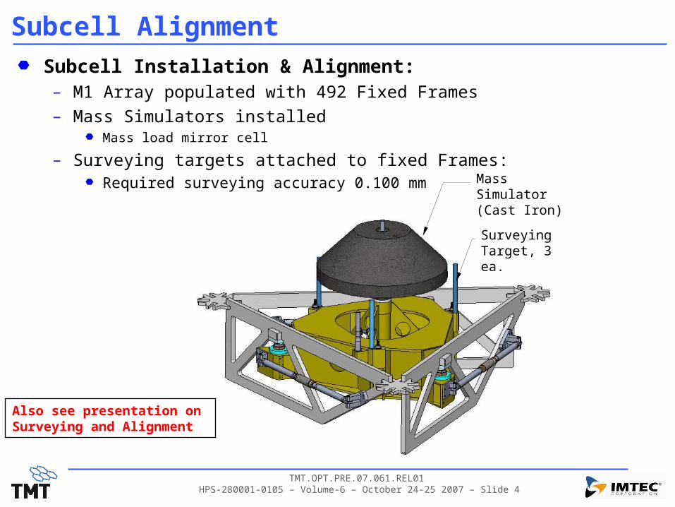
Subcell AlignmentSubcell Installation & Alignment:– M1 Array populated with 492 Fixed Frames
– Mass Simulators installedMass load mirror cell
– Surveying targets attached to fixed Frames:Required surveying accuracy 0.100 mm
Also see presentation on Surveying and Alignment
Mass Simulator(Cast Iron)
SurveyingTarget, 3 ea.

TMT.OPT.PRE.07.061.REL01 HPS-280001-0105 – Volume-6 – October 24-25 2007 – Slide 5
Fixed Frame InstallationInstall AAP Posts & Mount Fixed Frames in Nominal Position
Sectors A,C,E Sectors B,D,F
TMT.OPT.PRE.07.061.REL01 HPS-280001-0105 – Volume-6 – October 24-25 2007 – Slide 6
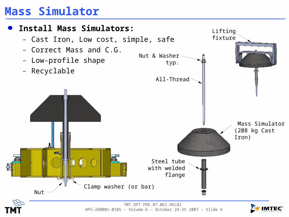
Mass SimulatorInstall Mass Simulators:– Cast Iron, Low cost, simple, safe
– Correct Mass and C.G.
– Low-profile shape
– Recyclable
Mass Simulator(208 kg Cast Iron)
NutClamp washer (or bar)
Steel tube with welded flange
Nut & Washertyp.
All-Thread
Lifting fixture
TMT.OPT.PRE.07.061.REL01 HPS-280001-0105 – Volume-6 – October 24-25 2007 – Slide 7
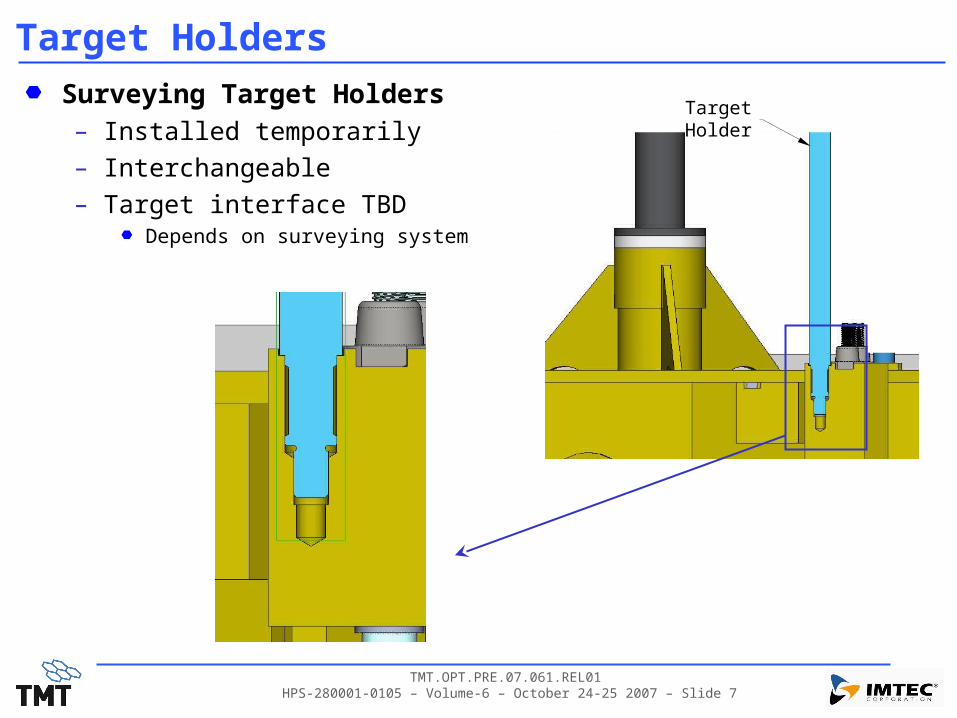
Target HoldersSurveying Target Holders– Installed temporarily– Interchangeable– Target interface TBD
Depends on surveying system
Target Holder

TMT.OPT.PRE.07.061.REL01 HPS-280001-0105 – Volume-6 – October 24-25 2007 – Slide 8
Subcell AlignmentSubcell Alignment:– Fixed Frame positioning – near kinematic:
3 ea. Positioners for three in-plane DOF– Precision turnbuckles– Removable tooling
3 ea AAP jacking screws for 3 out-of-plane DOF– AAP’s accommodate +/-8mm adjustment in-
planeCell mfg. tolerances & segmentation effects
– AAPs accommodate +/-5mm vertical adjustment
In-Plane Positioners (Removable Tooling)
See Vol-2: forAlignment budget

TMT.OPT.PRE.07.061.REL01 HPS-280001-0105 – Volume-6 – October 24-25 2007 – Slide 9
Subcell AlignmentSubcell Alignment:– AAP joint is secured after alignment
is complete:Top AAP disc pinned to fixed frame to prevent creep
Jam nuts tightened and thread-locker applied
Post: bolted to truss
Spherical Nut 2ea.
SphericalWasher 2ea.
Lock Nut 2ea.
Dowel Pins2 ea.

TMT.OPT.PRE.07.061.REL01 HPS-280001-0105 – Volume-6 – October 24-25 2007 – Slide 10
SEGMENT LIFTING JACK &LIFTING TALON
Integration & Handling

TMT.OPT.PRE.07.061.REL01 HPS-280001-0105 – Volume-6 – October 24-25 2007 – Slide 11
Lifting JackSegment Lifting Jack:– Function:
Raise and lower the MSA into and out of M1 array in a safe controlled mannerPrevent glass hitting glass during Installation & Removal (I&R)Compatible with crane and lifting talon operational sequencesCompatible with registration system
– Handoff without binding or overload
Light weight, simple, easy to operate, idiot-proof
– Requirements:Stroke 300 +/-2mm (increased over DRD reqt. (150mm) by agreement with Project)Lateral motion <0.5mm, Rotational motion: d < +/-0.5mm at vertex (DRD)
– See Jacking Gap Budget
Time for motion <1.0 minutesMaximum force applied < 1.5X weight of assembly being liftedTime for segment Removal and Installation 30 minutes
– ParametersFull extension at +300mmArray insertion at +95mm jack position (45mm mirror thickness+50mm sensor)Begin registration alignment at +10mm
TMT.OPT.PRE.07.061.REL01 HPS-280001-0105 – Volume-6 – October 24-25 2007 – Slide 12
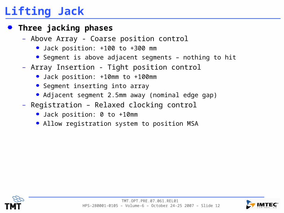
Lifting JackThree jacking phases– Above Array - Coarse position control
Jack position: +100 to +300 mm
Segment is above adjacent segments – nothing to hit
– Array Insertion - Tight position controlJack position: +10mm to +100mm
Segment inserting into array
Adjacent segment 2.5mm away (nominal edge gap)
– Registration – Relaxed clocking controlJack position: 0 to +10mm
Allow registration system to position MSA
TMT.OPT.PRE.07.061.REL01 HPS-280001-0105 – Volume-6 – October 24-25 2007 – Slide 13
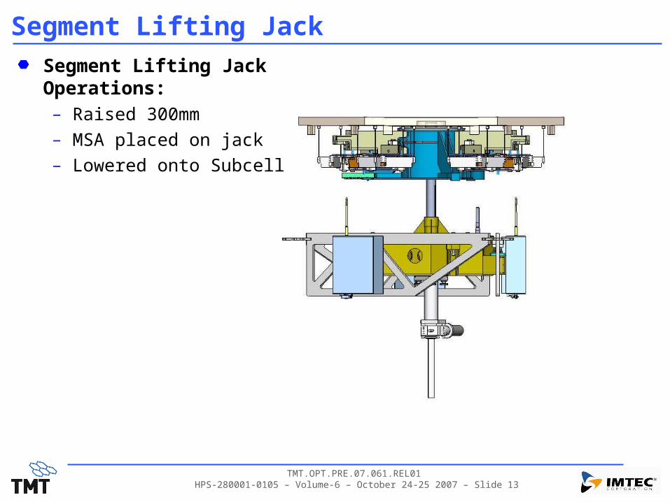
Segment Lifting JackSegment Lifting Jack Operations:– Raised 300mm– MSA placed on jack– Lowered onto Subcell
TMT.OPT.PRE.07.061.REL01 HPS-280001-0105 – Volume-6 – October 24-25 2007 – Slide 14
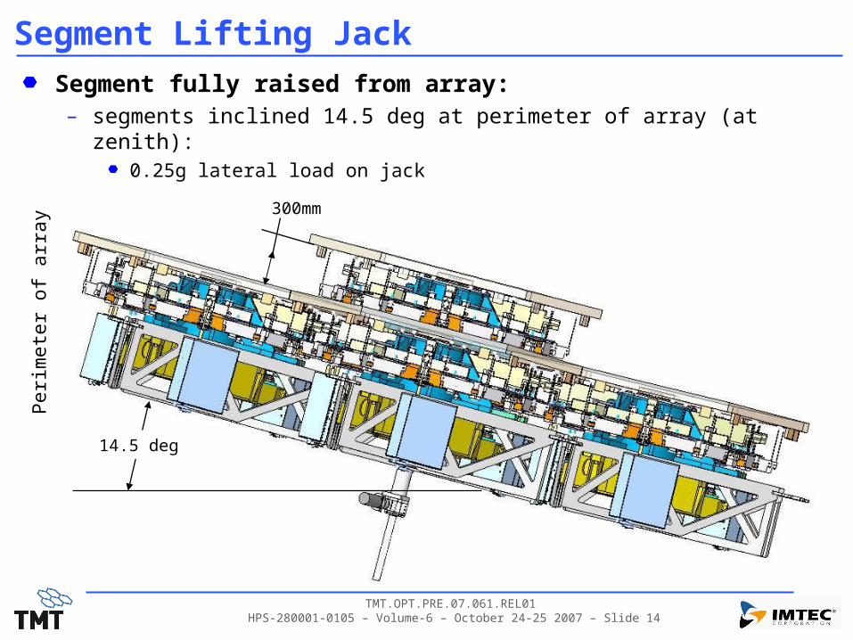
Segment Lifting JackSegment fully raised from array:– segments inclined 14.5 deg at perimeter of array (at zenith):
0.25g lateral load on jack
14.5 deg
300mm
Per
imet
er o
f arr
ay
TMT.OPT.PRE.07.061.REL01 HPS-280001-0105 – Volume-6 – October 24-25 2007 – Slide 15
Segment Lifting JackThree-Part Jack System– Removable Center-Shaft installs in fixed frame bushings
Stiff accurate control of segment
Shaft engages with moving frame– 6DOF control
Controlled clearances to permit PMA self-alignment on registration features– Shaft to moving frame clearance 0.5+/-.25mm on diameter– Permits small radial, tip/tilt and clocking motion
– Removable Motorized Screw JackMotor driven Trapezoidal Screw
– will not back-drive– motor circuit be sized to stall or shutoff at max design load (current)– bolts to fixed frame, self-aligns to center shaft
– Permanently installed Clocking PinAttached to fixed frame
Provides required clocking accuracy during array insertion (close tolerance)

TMT.OPT.PRE.07.061.REL01 HPS-280001-0105 – Volume-6 – October 24-25 2007 – Slide 16
Segment Lifting JackComponents of Jack System– Center-shaft: 5.2kg– Jack: 7.0 kg
Jack, motor, housing, end pad
Center Shaft
Spherical Radius (R250mm)(Permit tip/tilt at registration
Clocking grooveMoving frame pin engages in groove)
Nook ActionJacModel EM1-MSJ-1310mm stroke
TrackGroove
Clocking Pin(Engages in slot in tower)
Encoded StepperMotor

TMT.OPT.PRE.07.061.REL01 HPS-280001-0105 – Volume-6 – October 24-25 2007 – Slide 17
Fixed FrameFixed Frame (Top plate removed)
Actuator AttachmentCastings
Jack Center Shaft Support and Bushings
Registration Pins3 ea.
Tower Clocking Pin
AAP attach hole
Holes for surveying target holders 3ea.
Jack Center-Shaft Guide & Retention Pin
TMT.OPT.PRE.07.061.REL01 HPS-280001-0105 – Volume-6 – October 24-25 2007 – Slide 18
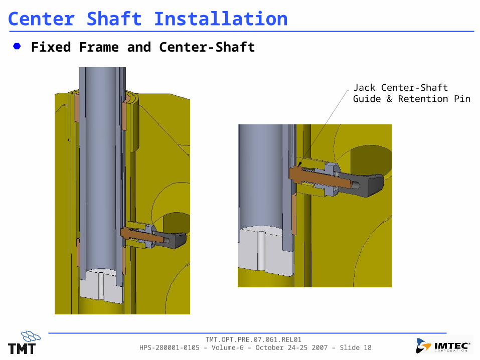
Center Shaft InstallationFixed Frame and Center-Shaft
Jack Center-Shaft Guide & Retention Pin
TMT.OPT.PRE.07.061.REL01 HPS-280001-0105 – Volume-6 – October 24-25 2007 – Slide 19
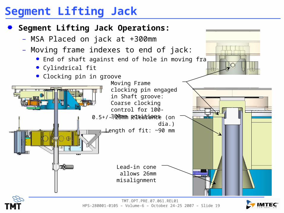
Segment Lifting JackSegment Lifting Jack Operations:– MSA Placed on jack at +300mm– Moving frame indexes to end of jack:
End of shaft against end of hole in moving frame
Cylindrical fit
Clocking pin in groove
0.5+/-.25mm clearance (on dia.)Length of fit: ~90 mm
Lead-in coneallows 26mm misalignment
Moving Frame clocking pin engaged in Shaft groove:Coarse clocking control for 100-300mm positions
TMT.OPT.PRE.07.061.REL01 HPS-280001-0105 – Volume-6 – October 24-25 2007 – Slide 20
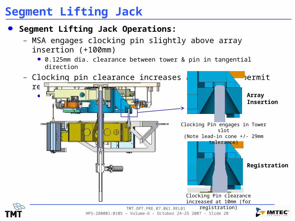
Segment Lifting JackSegment Lifting Jack Operations:– MSA engages clocking pin slightly above array insertion (+100mm)
0.125mm dia. clearance between tower & pin in tangential direction
– Clocking pin clearance increases at +10mm to permit registration motion1.0+/-0.1mm
Clocking Pin engages in Tower slot(Note lead-in cone +/- 29mm tolerance)
Clocking Pin clearance increased at 10mm (for registration)
ArrayInsertion
Registration
TMT.OPT.PRE.07.061.REL01 HPS-280001-0105 – Volume-6 – October 24-25 2007 – Slide 21
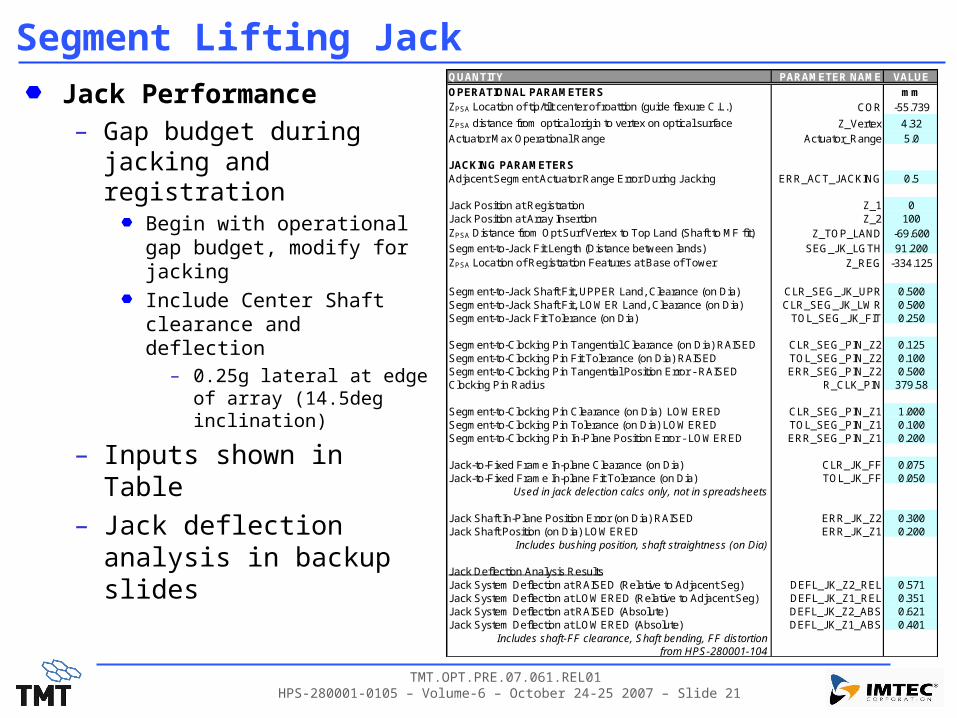
Segment Lifting JackJack Performance– Gap budget during jacking
and registrationBegin with operational gap budget, modify for jacking
Include Center Shaft clearance and deflection
– 0.25g lateral at edge of array (14.5deg inclination)
– Inputs shown in Table– Jack deflection analysis in
backup slides
QUANTITY PARAMETER NAME VALUE
OPERATIONAL PARAMETERS mmZPSA Location of tip/tilt center of roattion (guide flexure C.L.) COR -55.739
ZPSA distance from optical origin to vertex on optical surface Z_Vertex 4.32Actuator Max Operational Range Actuator_Range 5.0
JACKING PARAMETERSAdjacent Segment Actuator Range Error During Jacking ERR_ACT_JACKING 0.5
Jack Position at Registration Z_1 0Jack Position at Array Insertion Z_2 100ZPSA Distance from Opt Surf Vertex to Top Land (Shaft to MF fit) Z_TOP_LAND -69.600Segment-to-Jack Fit Length (Distance between lands) SEG_JK_LGTH 91.200ZPSA Location of Registration Features at Base of Tower Z_REG -334.125
Segment-to-Jack Shaft Fit, UPPER Land, Clearance (on Dia) CLR_SEG_JK_UPR 0.500Segment-to-Jack Shaft Fit, LOWER Land, Clearance (on Dia) CLR_SEG_JK_LWR 0.500Segment-to-Jack Fit Tolerance (on Dia) TOL_SEG_JK_FIT 0.250
Segment-to-Clocking Pin Tangential Clearance (on Dia) RAISED CLR_SEG_PIN_Z2 0.125Segment-to-Clocking Pin Fit Tolerance (on Dia) RAISED TOL_SEG_PIN_Z2 0.100Segment-to-Clocking Pin Tangential Position Error - RAISED ERR_SEG_PIN_Z2 0.500Clocking Pin Radius R_CLK_PIN 379.58
Segment-to-Clocking Pin Clearance (on Dia) LOWERED CLR_SEG_PIN_Z1 1.000Segment-to-Clocking Pin Tolerance (on Dia) LOWERED TOL_SEG_PIN_Z1 0.100Segment-to-Clocking Pin In-Plane Position Error - LOWERED ERR_SEG_PIN_Z1 0.200
Jack-to-Fixed Frame In-plane Clearance (on Dia) CLR_JK_FF 0.075Jack-to-Fixed Frame In-plane Fit Tolerance (on Dia) TOL_JK_FF 0.050
Used in jack delection calcs only, not in spreadsheets
Jack Shaft In-Plane Position Error (on Dia) RAISED ERR_JK_Z2 0.300Jack Shaft Position (on Dia) LOWERED ERR_JK_Z1 0.200
Includes bushing position, shaft straightness (on Dia)
Jack Deflection Analysis ResultsJack System Deflection at RAISED (Relative to Adjacent Seg) DEFL_JK_Z2_REL 0.571Jack System Deflection at LOWERED (Relative to Adjacent Seg) DEFL_JK_Z1_REL 0.351Jack System Deflection at RAISED (Absolute) DEFL_JK_Z2_ABS 0.621Jack System Deflection at LOWERED (Absolute) DEFL_JK_Z1_ABS 0.401
Includes shaft-FF clearance, Shaft bending, FF distortionfrom HPS-280001-104

TMT.OPT.PRE.07.061.REL01 HPS-280001-0105 – Volume-6 – October 24-25 2007 – Slide 22
Gap Budget during Jacking (@+100mm)GAP CLOSURE EFFECT MAGNI TUDE MULTI PLI ER* GAP LOSS, mmSegment edge & PMA assembly tolerance 0.300 1.00 0.300
Per Polished Mirror Assembly Drawing: 280-TMT-01-11000. Edge profile tolerance +/-.300mm WRT Tower [APPLIES TO ADJACENT SEGMENT]Segment edge to Moving Frame Bore Tolerance 0.150 1.00 0.150
Estimate, (APPLIES TO SEGMENT BEING JACKED)Subcell manufacturing/ assembly error (Target to Tower) 0.043 1.00 0.043
Accuracy from registration features to alignment targets. RSS of In-plane, Decenter and Clocking** (1/2 of P-P)) [APPLIES TO INSTALLED SEGMENT]
Subcell initial alignment error 0.115 1.41 0.163RSS of In-Plane, Decenter, & Clocking** (1/2 of P-P) [APPLIES TO BOTH SEGMENTS]
Surveying error 0.087 1.41 0.123RSS of In-Plane, Decenter, & Clocking** (1/2 of P-P) [APPLIES TO BOTH SEGMENTS]
SSA registration repeatability 0.083 1.00 0.083RSS of In-Plane, Decenter, & Clocking** (1/2 of P-P) [APPLIES TO INSTALLED SEGMENT]
Gravity-induced PSA deformations 0.010 1.00 0.010Assume max 5% difference in effective stiffness of neighboring PSA’s; 1g deflection=0.20mm based on fmin>35 hz.
Siesmic-induced PSA deformations 0.000 1.00 0.000Assume 0.1g reposne of PSAs. Adjacent PSAs out-of-phase. Basis: 1g deflection=0.203mm based on fmin>35 hz.
Temperature-Induced PSA translations 0.010 1.00 0.010Temperature gradients, CTE non-uniformity, PSA-PSA variations… ???
Temperature-Induced PSA rotations 0.046 1.00 0.046Cell/Subcell CTE mismatch: Adjacent segment clocking is out of phase at sector boundary. 6.4 u-rad/C * DT=10Cmax = 64u-rad each
Thermal expansion of cell 0.073 1.00 0.073Assume nominal gap is set for 0°C; steel cell (CTE~11.7 ppm/°C), max neg. ΔT=-5°C, 1.247m between segment centers)
Gravity-induced cell deflection 0.000 1.00 0.000Work done at zenith
Maximum gap closure before tip/ tilt (RSS of above contributions) 0.413
TYPE Actuation Adjacent Segment decenter due to tip/ tilt (est.) 0.038 1.00 0.038
2 Assumes 0.5 mm tilt of installed segment
Segment to J ack Shaft: I n-Plane plus Tip/ Tilt and Tol. 0.983 1.00 0.983Effect of Moving Frame-to-J ack Shaft Clearances (upper and lower lands) and Tolerances causing in-plane and Tip/Tilt decenter AT OPTICAL SURF.
Segment to Clocking Pin - Clocking 0.344 1.00 0.344Clearance, tolerance, and tangential error at clocking pin, reduced by 0.5 factor ** AT INSERTION
J ack Shaft position - I n Plane 0.150 1.00 0.150Shaft Straightness & Perp at shaft tip
J ack Shaft static deflection at edge of array (.25g) 0.571 1.00 0.571Shaft to Fixed Frame Tolerance and Clearance (0.025-.125mm dia max) included in the shaft deflection (kinematic + elastic) AT INSERTION
J ack I nduced Motion - LI NEAR SUM of above 2.048
Linear Sum of RSS'd Types 1-3 Errors 2.498
Nominal Gap Width 2.500
Gap Margin 0.002ZSEG Location of tip/tilt center of rotation, mm = Actuator radius, mm = 531.0
* Multiplier relates single segment effect to total change in gap. Random effects on adjacent segments are RSS'd, giving the 1.41 factor.
** Clocking at vertex results in gap closure: DGap = D * sin(30) = 0.5*symbol
PS
A M
an
ufa
ctu
re &
In
sta
llati
on
TY
PE-1
Gap
Eff
ects
TY
PE-3
Gap
Eff
ects
Jack M
oti
on
at
Insert
ion
in
to
Arr
ay
En
vir
on
men
tal
ly I
nd
uced
P
SA
Moti
on
s
Cell Motion

TMT.OPT.PRE.07.061.REL01 HPS-280001-0105 – Volume-6 – October 24-25 2007 – Slide 23
Gap Budget during Jacking (@+10mm)GAP CLOSURE EFFECT MAGNI TUDE MULTI PLI ER* GAP LOSS, mmSegment edge & PMA assembly tolerance 0.300 1.00 0.300
Per Polished Mirror Assembly Drawing: 280-TMT-01-11000. Edge profile tolerance +/-.300mm WRT Tower [APPLIES TO ADJACENT SEGMENT]Segment edge to Moving Frame Bore Tolerance 0.150 1.00 0.150
Estimate, (APPLIES TO SEGMENT BEING JACKED)Subcell manufacturing/ assembly error (Target to Tower) 0.043 1.00 0.043
Accuracy from registration features to alignment targets. RSS of In-plane, Decenter and Clocking** (1/2 of P-P)) [APPLIES TO INSTALLED SEGMENT]
Subcell initial alignment error 0.115 1.41 0.163RSS of In-Plane, Decenter, & Clocking** (1/2 of P-P) [APPLIES TO BOTH SEGMENTS]
Surveying error 0.087 1.41 0.123RSS of In-Plane, Decenter, & Clocking** (1/2 of P-P) [APPLIES TO BOTH SEGMENTS]
SSA registration repeatability 0.083 1.00 0.083RSS of In-Plane, Decenter, & Clocking** (1/2 of P-P) [APPLIES TO INSTALLED SEGMENT]
Gravity-induced PSA deformations 0.010 1.00 0.010Assume max 5% difference in effective stiffness of neighboring PSA’s; 1g deflection=0.20mm based on fmin>35 hz.
Siesmic-induced PSA deformations 0.000 1.00 0.000Assume 0.1g reposne of PSAs. Adjacent PSAs out-of-phase. Basis: 1g deflection=0.203mm based on fmin>35 hz.
Temperature-Induced PSA translations 0.010 1.00 0.010Temperature gradients, CTE non-uniformity, PSA-PSA variations… ???
Temperature-Induced PSA rotations 0.046 1.00 0.046Cell/Subcell CTE mismatch: Adjacent segment clocking is out of phase at sector boundary. 6.4 u-rad/C * DT=10Cmax = 64u-rad each
Thermal expansion of cell 0.073 1.00 0.073Assume nominal gap is set for 0°C; steel cell (CTE~11.7 ppm/°C), max neg. ΔT=-5°C, 1.247m between segment centers)
Gravity-induced cell deflection 0.000 1.00 0.000Work done at zenith
Maximum gap closure before tip/ tilt (RSS of above contributions) 0.413
TYPE Actuation Adjacent Segment decenter due to tip/ tilt (est.) 0.038 1.00 0.038
2 Assumes 0.5 mm tilt of installed segment
Segment to J ack Shaft: I n-Plane plus Tip/ Tilt and Tol. 0.983 1.00 0.983Effect of Moving Frame-to-J ack Shaft Clearances (upper and lower lands) and Tolerances causing in-plane and Tip/Tilt decenter AT OPTICAL SURF.
Segment to Clocking Pin - Clocking 0.616 1.00 0.616Clearance, tolerance, and tangential error at clocking pin, reduced by 0.5 factor ** AT REGISTRATION
J ack Shaft position - I n Plane 0.100 1.00 0.100Shaft Straightness & Perp at shaft tip
J ack Shaft static deflection at edge of array (.25g) 0.351 1.00 0.351Shaft to Fixed Frame Tolerance and Clearance (0.025-.125mm dia max) included in the shaft deflection (kinematic + elastic) AT REGISTRATION
J ack I nduced Motion - LI NEAR SUM of above 2.050
Linear Sum of RSS'd Types 1-3 Errors 2.501
Nominal Gap Width 2.500
Gap Margin -0.001ZSEG Location of tip/tilt center of rotation, mm = Actuator radius, mm = 531.0
* Multiplier relates single segment effect to total change in gap. Random effects on adjacent segments are RSS'd, giving the 1.41 factor.
** Clocking at vertex results in gap closure: DGap = D * sin(30) = 0.5*symbol
PS
A M
an
ufa
ctu
re &
In
sta
llati
on
TY
PE-1
Gap
Eff
ects
TY
PE-3
Gap
Eff
ects
Jack M
oti
on
at
Insert
ion
in
to
Arr
ay
En
vir
on
men
tal
ly I
nd
uced
P
SA
Moti
on
s
Cell Motion

TMT.OPT.PRE.07.061.REL01 HPS-280001-0105 – Volume-6 – October 24-25 2007 – Slide 24
Segment Lifting JackSummary– Design concept meets requirements
Gap budget is tight
Glass-to-glass impact will likely occur during earthquake– protect segment corners with Kapton tape as a minimum
Jack motor type needs to be agreed upon

TMT.OPT.PRE.07.061.REL01 HPS-280001-0105 – Volume-6 – October 24-25 2007 – Slide 25
Lifting TalonLifting Talon CONCEPT Design– Requirements:
Safety: FSy > 3.0 for 2g load
Fail-safe (segment cannot be dropped)
Interlocked to assure mate to moving frame
Accommodate 14.5 deg inclination range (tip/tilt adjustment)
– Crane Assumption: Crane accurate to +/-5mm all directions
Crane can move Talon in direction normal to optical surface for segment installation & removal

TMT.OPT.PRE.07.061.REL01 HPS-280001-0105 – Volume-6 – October 24-25 2007 – Slide 26
Lifting TalonLifting Talon:– Talon claws motorized
Low torque motor for safety
Claw pivot point in-board of contact point– self-closing
Interlocks– Open/closed positions
– Moving frame capture (3)
– Vertical contact: moving frame-to-claw (3)
– Talon instrumentedLoad cell with 5N resolution
– to sense segment weight during handoff
– Tip/Tilt adjustableSet to match segment inclination
Tip/Tilt Adjusters

TMT.OPT.PRE.07.061.REL01 HPS-280001-0105 – Volume-6 – October 24-25 2007 – Slide 27
Lifting TalonLifting Talon Interface to Moving Frame:– Moving Frame captured by Talon:
Fail safe, MSA cannot fall off crane - Interlocked
– Self-aligning, kinematic joint – Cylinder in V-groove
Plastic Entrance PieceProtects mirror if accidental
contact occurs
Moving Frame
Lifting Talon
Self-aligning, kinematic joint
V-groove in moving frame

TMT.OPT.PRE.07.061.REL01 HPS-280001-0105 – Volume-6 – October 24-25 2007 – Slide 28
Talon ConceptVertical Contact Switches– Talon opened and closed when both are “green”
Upper
Lower
Upper
Lower
Upper
Lower
Contact - Low Contact - High
LOW HIGH CLEAR (OK to OPEN)
TMT.OPT.PRE.07.061.REL01 HPS-280001-0105 – Volume-6 – October 24-25 2007 – Slide 29
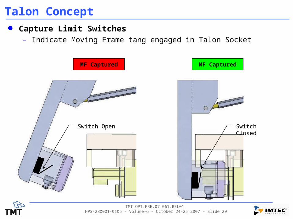
Talon ConceptCapture Limit Switches– Indicate Moving Frame tang engaged in Talon Socket
Switch Closed
MF Captured MF Captured
Switch Open

TMT.OPT.PRE.07.061.REL01 HPS-280001-0105 – Volume-6 – October 24-25 2007 – Slide 30
Lifting TalonSegment Removal Sequence– Segment lifted to full stroke: 300mm
– Talon lowered (Claws open)stop at 5-15 mm below capture height
– Talon closedInterlocks verified
– Check Talon closed?– Check moving frame tang inserted in socket?
– Jack begins to lowerTalon Load Cell monitors handoff
Expect TBD weight on Talon after TBD Jack Motion
– TBDs Depend on Crane stiffness
Jack stops after retracting 40mm
– With handoff verifiedSegment extracted
Crane Departs
– Jack re-positioned to receive new MSA
Jack Raises Segment +300mmTalon is lowered into positionTalon ClosesJack lowers segment onto TalonCrane extracts Talon and Segment
Upper
Lower
MF Captured
INTERLOCKS
Upper
Lower
MF Captured
INTERLOCKS
Upper
Lower
MF Captured
INTERLOCKS

TMT.OPT.PRE.07.061.REL01 HPS-280001-0105 – Volume-6 – October 24-25 2007 – Slide 31
Lifting TalonSegment Installation Sequence– Jack set to 260mm
full stroke less 40mm
– Crane lowers Talon & Segment toward array
– Moving frame engages onto Jack Center Shaft
– Crane stops at segment height 275-285mm
65-75mm engagement on jack shaft
– Jack extended until MF liftoff detectedIndicator lights on Talon verify handoff
– Talon opens
– Crane departs
– Jack lower segment into position.
Jack raised to +260mmCrane lowers segment onto JackPosition: +275-285mm
Jack raised until MF liftoffCrane and Talon DepartJack lowers segment into arraySegment on Jack, Talon opened
Upper
Lower
Upper
Lower
MF CapturedMF Captured
INTERLOCKS
TMT.OPT.PRE.07.061.REL01 HPS-280001-0105 – Volume-6 – October 24-25 2007 – Slide 32
ConclusionsTalon/Crane/Jack Integration is challenging– Talon design requires certain crane accuracy and motion
– Ongoing work will integrate systems

TMT.OPT.PRE.07.061.REL01 HPS-280001-0105 – Volume-6 – October 24-25 2007 – Slide 33
Acknowledgements
Acknowledgements:
The TMT Project gratefully acknowledges the support of the TMT partner institutions. They are the Association of Canadian Universities for Research in Astronomy (ACURA), the California Institute of Technology and the University of California. This work was supported as well by the Gordon and Betty Moore Foundation, the Canada Foundation for Innovation, the Ontario Ministry of Research and Innovation, the National Research Council of Canada, the Natural Sciences and Engineering Research Council of Canada, the British Columbia Knowledge Development Fund, the Association of Universities for Research in Astronomy (AURA) and the U.S. National Science Foundation.
TMT.OPT.PRE.07.061.REL01 HPS-280001-0105 – Volume-6 – October 24-25 2007 – Slide 34
BACKUP SLIDES
TMT.OPT.PRE.07.061.REL01 HPS-280001-0105 – Volume-6 – October 24-25 2007 – Slide 35
JACK SHAFT DEFLECTION ANALYSIS
Integration & Handling

TMT.OPT.PRE.07.061.REL01 HPS-280001-0105 – Volume-6 – October 24-25 2007 – Slide 36
Bushing Arrangement
d
Dimensions:– ID = 35mm
– OD = 50mm
– Length = 28.575mm
– Center to center distance: d
– 28.6mm ≤ d ≤ 291.4mm
Material properties:– E = 76GPa
– ≈ 0.3
– (c)All ≈ 31.03MPa

TMT.OPT.PRE.07.061.REL01 HPS-280001-0105 – Volume-6 – October 24-25 2007 – Slide 37
d
L
F
R1 R2
Simplified Beam Model
EI
LdFLwe
3
)(2
)/1(2 dLcwk
Elastic deflection (simply supported overhang beam)– Assumption: rigid fixed frame– F ≈ 210g × Sin(14.5°) = 515.8N– L = 281.9mm (SSA lifted 100mm)– E = 200GPa– I = 2.33×10⁻⁷m4
Kinematic deflection– c = cmax
= 0.0625mm
– 28.6mm ≤ d ≤ 291.4mm
Total deflection
Reaction forces
Contact stress in Bronze bushings– Allowable contact stress ≈ 31.03MPa– Bushing length = 2 × 28.575mm
– KD = 2E4m
– CE = 1.64E-11m2/N
– p = R / 0.028575
)/1(
/
2
1
dLFR
dFLR
EDc CK
pmax)(
Radial clearance c
ket www
TMT.OPT.PRE.07.061.REL01 HPS-280001-0105 – Volume-6 – October 24-25 2007 – Slide 38
Optimal Bushing Distance
0.00
0.20
0.40
0.60
0.80
1.00
1.20
1.40
1.60
0 50 100 150 200 250 300 350
Bushing Distance (mm)
De
fle
cti
on
(m
m)
Kinematic Deflection Elastic Deflection
Total Deflection Optimal Bushing Distance
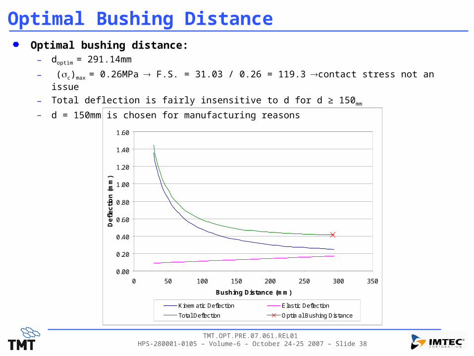
Optimal bushing distance:– doptim = 291.14mm
– (c)max = 0.26MPa F.S. = 31.03 / 0.26 = 119.3 contact stress not an issue
– Total deflection is fairly insensitive to d for d ≥ 150mm
– d = 150mm is chosen for manufacturing reasons

TMT.OPT.PRE.07.061.REL01 HPS-280001-0105 – Volume-6 – October 24-25 2007 – Slide 39
Relative Deflections
2
1
Installed Configuration Lifted 100mm
Deflections at 14.5°:– 1: static deflection with mirror at the operational z
– 2: static deflection with SSA 100mm lifted
– k: kinematic deflection of the shaft due to bushing clearances
TMT.OPT.PRE.07.061.REL01 HPS-280001-0105 – Volume-6 – October 24-25 2007 – Slide 40
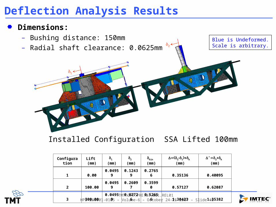
Deflection Analysis Results
2
1
Configuration
Lift (mm)
1
(mm)
2
(mm)
kin
(mm)
D21k
(mm)
D’2k
(mm)
1 0.00 0.04959 0.12439 0.27656 0.35136 0.40095
2 100.00 0.04959 0.26097 0.35990 0.57127 0.62087
3 300.00 0.04959 0.82726 0.52656 1.30423 1.35382
Dimensions:– Bushing distance: 150mm
– Radial shaft clearance: 0.0625mmBlue is Undeformed.Scale is arbitrary.
Installed Configuration SSA Lifted 100mm