TM1000 User Guide TM1000 Bedienungsanleitung TM1000 Guide ... · TM1000 User Guide TM1000...
13
TM1000 User Guide TM1000 Bedienungsanleitung TM1000 Guide de l’utilisateur TM1000 Guida per l’utente
Transcript of TM1000 User Guide TM1000 Bedienungsanleitung TM1000 Guide ... · TM1000 User Guide TM1000...

TM1000 User Guide
TM1000 Bedienungsanleitung
TM1000 Guide de l’utilisateur
TM1000 Guida per l’utente

EN
NOTICEAll instructions, warranties and other collateral documents are subject to change at the
sole discretion of Horizon Hobby, Inc. For up to date product literature, visit http://www.horizonhobby.com/ProdInfo/Files/SPM9548-manual.pdf.
Meaning of Special Language:The following terms are used throughout the product literature to indicate various levels of potential harm when operating this product:
NOTICE: Procedures, which if not properly followed, create a possibility of physical property damage AND a little or no possibility of injury
CAUTION: Procedures, which if not properly followed, create the probability of physical property damage AND a possibility of serious injury.
WARNING: Procedures, which if not properly followed, create the probability of property damage, collateral damage, and serious injury OR create a high probability of superficial injury.
WARNING: Read the ENTIRE instruction manual to become familiar with the features of the product before operating. Failure to operate
the product correctly can result in damage to the product, personal property and cause serious injury.
This is a sophisticated hobby product and NOT a toy. It must be operated with caution and common sense and requires some basic mechanical ability. Failure to operate this Product in a safe and responsible manner could result in injury or damage to the product or other property. This product is not intended for use by children without direct adult supervision. Do not attempt disassembly, use with incompatible components or augment product in any way without the approval of Horizon Hobby, Inc. This manual contains instructions for safety, operation and maintenance. It is essential to read and follow all the instructions and warnings in the manual, prior to assembly, setup or use, in order to operate correctly and avoid damage or serious injury.

EN
TM1000 Telemetry Module User Guide Spektrum’s TM1000 telemetry module is compatible with all Spektrum™ and JR® receivers that have a Data (Flight Log) port including:
Spektrum
•AR6255 •AR7000 •AR7100 •AR7100R •AR7600 •AR8000 •AR9000 •AR9100 •AR9200 •AR9300 •AR12000 •AR12100 JR
•R921 •R922 •R1221 •R1222
Specifications: Type:TM1000Telemetrymodule OperationalVoltage:3.5to9.6volts Dimensions:43x25x12mm Weight:15.8g RPMRange:0to65,500 FlightPackVoltageRange:0–60V TemperatureRange:-40°Fto1000°F/-40°Cto538°C ReceiverVolts:0–8.0V
Items Included
•TM1000telemetrymodule •2.5”Datalead •20”Externalvoltagesensor •20”Temperaturesensor •2.5”AircrafttelemetryY-harness(usedwhenTempandvoltsareused
simultaneously) •TM1000Manual

EN
Hook up
Installation and Hook Up Information
Installing the TM1000 Module
MounttheTM1000modulenearthereceiverinapositionthatallowsthe2.5-inchdataleadtoextendfromthereceiver’sDataporttotheDataportonthetelemetrymodule.Youcan use servo tape to secure the TM1000 module or wrap it in foam with the receiver. Plug the Data lead into the TM1000 port marked DATA and plug the other end of the lead into the receiver’s DATA port.
NOTICE: Route and secure the antenna away from any metallic or conductive materials to give the best range.
At this point the internal telemetry DATA is now fully functional. This includes:
•Flightlogdata(fades,framelossesandholds) •Receiverpackvoltage
Before continuing, bind the system to the transmitter and confirm the telemetry system is functioning.
Bind Stylus
Data Port with Data Lead
Temp/Volt Port withY-Harness
Temperature Lead Voltage Lead
X-Bus (for future telemetry options)
RPM Port
Antenna
Optional RPM Sensor (nitro)OptionalElectricRPMSensor
(not attached)
Bind Button
EN
Binding the Telemetry Module and Receiver
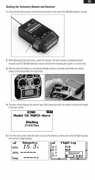
1. Using the Bind Stylus press and hold the bind button on the side of the TM1000 telemetry module.
2. While depressing the bind button, power the receiver. The main receiver, all attached remote receivers and the TM1000 telemetry module should blink indicating the system is in bind mode.
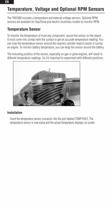
3. With the stick and switches in the desired failsafe positions (normally low throttle and neutral sticks), put the transmitter into bind mode.
4. The main screen displays the receiver type. After several seconds, the system connects and reverts to the main screen.
5. From the main screen rotate the roller to access the telemetry screens and verify the flight log data and receiver voltage displays.
EN
Temperature, Voltage and Optional RPM Sensors
TheTM1000includesatemperatureandexternalvoltagesensors.OptionalRPMsensors are available for Gas/Glow and electric brushless models to monitor RPM.
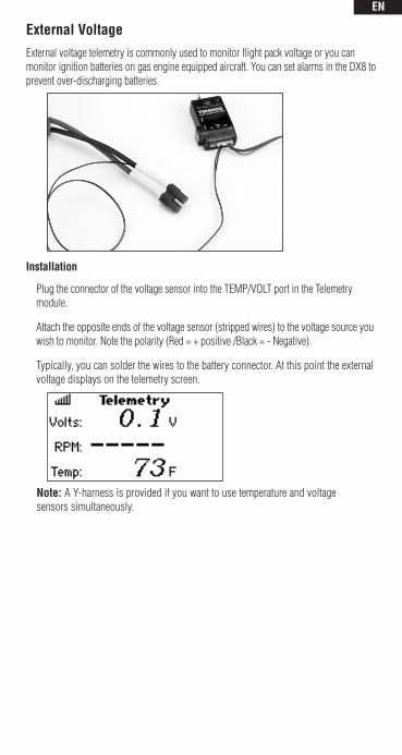
Temperature SensorTo monitor the temperature of most any component, secure the sensor on the object. Itmustcomeintocontactwiththesurfacetogetanaccuratetemperaturereading.Youcan loop the temperature sensor around the engine’s cylinder head to assist in tuning an engine. To monitor battery temperature, you can wrap the sensor around the battery.
The mounting position of the sensor, especially on gas or glow engines, will result in differenttemperaturereadings.Soit’simportanttoexperimentwithdifferentpositions.
Installation
InsertthetemperaturesensorconnectorintotheportlabeledTEMP/VOLT.Thetemperature sensor is now active and the actual temperature displays on screen.
EN
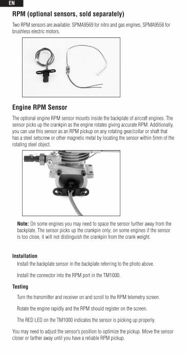
External VoltageExternalvoltagetelemetryiscommonlyusedtomonitorflightpackvoltageoryoucanmonitorignitionbatteriesongasengineequippedaircraft.YoucansetalarmsintheDX8toprevent over-discharging batteries.
Installation
PlugtheconnectorofthevoltagesensorintotheTEMP/VOLTportintheTelemetrymodule.
Attach the opposite ends of the voltage sensor (stripped wires) to the voltage source you wish to monitor. Note the polarity (Red = + positive /Black = - Negative).
Typically,youcansolderthewirestothebatteryconnector.Atthispointtheexternalvoltage displays on the telemetry screen.
Note:AY-harnessisprovidedifyouwanttousetemperatureandvoltagesensors simultaneously.
EN
RPM (optional sensors, sold separately)Two RPM sensors are available: SPMA9569 for nitro and gas engines, SPMA9558 for brushless electric motors.
Engine RPM SensorThe optional engine RPM sensor mounts inside the backplate of aircraft engines. The sensor picks up the crankpin as the engine rotates giving accurate RPM. Additionally, you can use this sensor as an RPM pickup on any rotating gear/collar or shaft that has a steel setscrew or other magnetic metal by locating the sensor within 5mm of the rotating steel object.
Note: On some engines you may need to space the sensor further away from the backplate. The sensor picks up the crankpin only; on some engines if the sensor is too close, it will not distinguish the crankpin from the crank weight.
Installation Install the backplate sensor in the backplate referring to the photo above.
Install the connector into the RPM port in the TM1000.
Testing
Turn the transmitter and receiver on and scroll to the RPM telemetry screen.
Rotate the engine rapidly and the RPM should register on the screen.
TheREDLEDontheTM1000indicatesthesensorispickingupproperly.
Youmayneedtoadjustthesensor’spositiontooptimizethepickup.Movethesensorcloser or farther away until you have a reliable RPM pickup.

EN
Electric RPM SensorThe optional electric RPM sensor is designed to be used with any brushless motor. The sensor has two leads to attach to any two of the three motor wires. This is typically done by soldering.
Installation
To install the electric RPM sensor using servo tape, attach the sensor in a convenient place that allows the leads to reach the motor wires and the TM1000 telemetry unit.
Solder the two sensor wires to any two motor leads.
Plug the sensor lead into the RPM port on the TM1000 telemetry module.
Testing
Turn the transmitter and receiver on and scroll to the RPM telemetry screen.
Run the motor and the RPM should register on the screen.
TheREDLEDontheTM1000indicatesthesensorispickingupproperly.
NOTICE: It is necessary to program a matching pole count in the telemetry RPM screen to have accurate reading on screen. The motor’s pole count is normally in the motor manufacturer’s instructions or on the manufacturer’s website.

EN
WARRANTY AND REPAIR POLICY
Warranty PeriodExclusiveWarranty-HorizonHobby,Inc.,(Horizon)warrantiesthattheProductspurchased(the“Product”)will be free from defects in materials and workmanship for a period of 1 year from the date of purchase by the Purchaser.
1-Year Limited WarrantyHorizon reserves the right to change or modify this warranty without notice and disclaims all other warranties, express or implied.
(a)ThiswarrantyislimitedtotheoriginalPurchaser(“Purchaser”)andisnottransferable.REPAIRORREPLACEMENTASPROVIDEDUNDERTHISWARRANTYISTHEEXCLUSIVEREMEDYOFTHEPURCHASER.ThiswarrantycoversonlythoseProductspurchasedfromanauthorizedHorizondealer.Third party transactions are not covered by this warranty. Proof of purchase is required for all warranty claims.
(b)Limitations-HORIZONMAKESNOWARRANTYORREPRESENTATION,EXPRESSORIMPLIED,ABOUTNON-INFRINGEMENT,MERCHANTABILITYORFITNESSFORAPARTICULARPURPOSEOFTHEPRODUCT.THEPURCHASERACKNOWLEDGESTHATTHEYALONEHAVEDETERMINEDTHATTHEPRODUCTWILLSUITABLYMEETTHEREQUIREMENTSOFTHEPURCHASER’SINTENDEDUSE.
(c) Purchaser Remedy- Horizon’s sole obligation hereunder shall be that Horizon will, at its option, (i) repair or (ii) replace, any Product determined by Horizon to be defective. In the event of a defect, these are thePurchaser’sexclusiveremedies.Horizonreservestherighttoinspectanyandallequipmentinvolvedin a warranty claim. Repair or replacement decisions are at the sole discretion of Horizon. This warranty does not cover cosmetic damage or damage due to acts of God, accident, misuse, abuse, negligence, commercial use, or modification of or to any part of the Product. This warranty does not cover damage due to improper installation, operation, maintenance, or attempted repair by anyone other than Horizon. Return of any Product by Purchaser must be approved in writing by Horizon before shipment.
Damage LimitsHORIZONSHALLNOTBELIABLEFORSPECIAL,INDIRECTORCONSEQUENTIALDAMAGES,LOSSOFPROFITSORPRODUCTIONORCOMMERCIALLOSSINANYWAYCONNECTEDWITHTHEPRODUCT,WHETHERSUCHCLAIMISBASEDINCONTRACT,WARRANTY,NEGLIGENCE,ORSTRICTLIABILITY.Further,innoeventshalltheliabilityofHorizonexceedtheindividualpriceoftheProductonwhichliability is asserted. As Horizon has no control over use, setup, final assembly, modification or misuse, no liability shall be assumed nor accepted for any resulting damage or injury. By the act of use, setup or assembly, the user accepts all resulting liability.
If you as the Purchaser or user are not prepared to accept the liability associated with the use of this Product, you are advised to return this Product immediately in new and unused condition to the place of purchase.
Law: These Terms are governed by Illinois law (without regard to conflict of law principals).
WARRANTY SERVICESQuestions, Assistance, and RepairsYourlocalhobbystoreand/orplaceofpurchasecannotprovidewarrantysupportorrepair.Onceassembly,setup or use of the Product has been started, you must contact Horizon directly. This will enable Horizon to better answer your questions and service you in the event that you may need any assistance. For questions orassistance,[email protected],orcall877.504.0233tollfreetospeaktoaProductSupportrepresentative.Youmayalsofindinformationonourwebsiteatwww.horizonhobby.com.
Inspection or RepairsIf this Product needs to be inspected or repaired, please use the Horizon Online Repair Request submission process found on our website or call Horizon to obtain a Return Merchandise Authorization (RMA) number. PacktheProductsecurelyusingashippingcarton.Pleasenotethatoriginalboxesmaybeincluded,but are not designed to withstand the rigors of shipping without additional protection. Ship via a carrier that provides tracking and insurance for lost or damaged parcels, as Horizon is not responsible for
EN
merchandise until it arrives and is accepted at our facility. An Online Repair Request is available at www.horizonhobby.com http://www.horizonhobby.com under the Repairs tab. If you do not have internet access, please contact Horizon Product Support to obtain a RMA number along with instructions for submitting your product for repair. When calling Horizon, you will be asked to provide your complete name, street address, email address and phone number where you can be reached during business hours. When sending product into Horizon, please include your RMA number, a list of the included items, and a brief summary of the problem. A copy of your original sales receipt must be included for warranty consideration. Be sure your name, address, and RMA number are clearly written on the outside of the shipping carton.
Notice: Do not ship batteries to Horizon. If you have any issue with a battery, please contact the appropriate Horizon Product Support office.
Warranty Inspection and RepairsTo receive warranty service, you must include your original sales receipt verifying the proof-of-purchase date. Provided warranty conditions have been met, your Product will be repaired or replaced free of charge. Repair or replacement decisions are at the sole discretion of Horizon Hobby.
Non-Warranty RepairsShould your repair not be covered by warranty the repair will be completed and payment will be required without notification or estimate of the expense unless the expense exceeds 50% of the retail purchase cost. By submitting the item for repair you are agreeing to paymentoftherepairwithoutnotification.Repairestimatesareavailableuponrequest.Youmustincludethis request with your repair. Non-warranty repair estimates will be billed a minimum of ½ hour of labor. In addition you will be billed for return freight. Horizon accepts money orders and cashiers checks, as well as Visa,MasterCard,AmericanExpress,andDiscovercards.BysubmittinganyitemtoHorizonforinspectionorrepair,youareagreeingtoHorizon’sTermsandConditionsfoundonourwebsiteundertheRepairstab.
FCC InformationThisdevicecomplieswithpart15oftheFCCrules.Operationissubjecttothefollowingtwoconditions:(1)Thisdevicemaynotcauseharmfulinterference,and(2)thisdevicemustacceptanyinterference received, including interference that may cause undesired operation.
Caution: Changesormodificationsnotexpresslyapprovedbythepartyresponsibleforcompliance could void the user’s authority to operate the equipment.
This product contains a radio transmitter with wireless technology which has been tested and found tobecompliantwiththeapplicableregulationsgoverningaradiotransmitterinthe2.400GHzto2.4835GHzfrequencyrange.
Country of Purchase Horizon Hobby Address Phone Number/ EmailUnited States Horizon Service Center
(Electronics and engines)
4105 Fieldstone RdChampaign, Illinois61822 USA
877-504-0233
Horizon Product Support
(All other products)
4105 Fieldstone RdChampaign, Illinois61822 USA
877-504-0233
United Kingdom Horizon Hobby Limited Units 1-4 Ployters RdStaple TyeHarlow, EssexCM18 7NSUnited Kingdom
+44 (0) 1279 641 097
Germany Horizon Technischer Service
Hamburger Str. 1025335 ElmshornGermany
+49 4121 46199 66
France Horizon Hobby SAS 14 Rue Gustave EiffelZone d’Activité du Réveil Matin91230 Montgeron
+33 (0) 1 60 47 44 70
Online Repair Request visit: www.horizonhobby.com/repairs

EN
Compliance Information for the European Union
Declaration of Conformity(inaccordancewithISO/IEC17050-1)
No.HH2010082102
Product(s): Spektrum TM1000 Telemetry Module
Item Number(s): SPM9548
Equipmentclass: 2
The objects of declaration described above are in conformity with the requirements of the specificationslistedbelow,followingtheprovisionsoftheEuropeanR&TTEdirective1999/5/EC:
EN 301 489 General EMC requirements
EN 300-328 Technical requirements for Radio equipment.
Signed for and on behalf of: Horizon Hobby, Inc. Champaign,ILUSA Aug21,2010
Instructions for Disposal of WEEE by Users in the European UnionThis product must not be disposed of with other waste. Instead, it is the user’s
responsibility to dispose of their waste equipment by handing it over to a designated collection point for the recycling of waste electrical and electronic equipment. The separate collection and recycling of your waste equipment at the time of disposal will help to conserve natural resources and ensure that it is recycled in a manner that protects human health and the environment. For more information about where you can drop off your waste equipment for recycling, please contact your local city office, your household waste disposal service or where you purchased the product.
Steven A. Hall Vice President International Operations and Risk Management Horizon Hobby, Inc.
The following information is for item numbers: SPM9548
AT BG CZ CY DE
DK ES FI GR HU
IE IT LT LU LV
MT NL PL PT RO
SE SI SK UK

IT
©2010HorizonHobby,Inc.DSMandDSM2aretrademarksorregisteredtrademarksofHorizonHobby,Inc.The Spektrum trademark is used with permission of Bachmann Industries, Inc.SpektrumradiosandaccessoriesareexclusivelyavailablefromHorizonHobby,Inc.
Printed12/1016499.1


![MTM800E FEATURE USER GUIDE / AUSFÜHRLICHE BEDIENUNGSANLEITUNG · .xu]zdko (lqhq.rqwdnwhuvwhoohq](https://static.fdocuments.in/doc/165x107/5dd0ecedd6be591ccb635e53/mtm800e-feature-user-guide-ausfoehrliche-bedienungsanleitung-xuzdko-lqhqrqwdnwhuvwhoohq.jpg)