TM-S Fusion Device - Joint Replacement | Orthopaedic ... · 1...
28
zimmerspine.com TM-S Fusion Device Trabecular Metal TM Technology Surgical Technique
Transcript of TM-S Fusion Device - Joint Replacement | Orthopaedic ... · 1...
zimmerspine.com
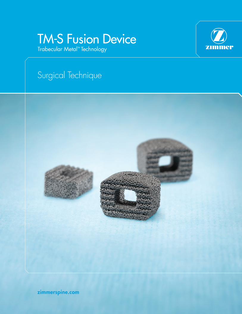
TM-S Fusion DeviceTrabecular MetalTM Technology
Surgical Technique


Table of ContentsDescription/Indications/Contraindications 1
TM-S Implants 3
Mergence-S Instruments 5
Surgical Technique 7
Kit Contents 15
Warnings and Precautions 22
1
Description/Indications/Contraindications
Description
The TM-S Fusion Device is a single device manufactured wholly from Trabecular Metal porous tantalum.
The device is a trapezoidal shape and is available in a variety of cross-sectional geometries and sizes.
It is offered in a 7° included angle option and a 0° included angle option to help maintain the natural
contour of the spine.
The superior and inferior surfaces of the device have a textured surface to provide increased stability. It
has a central hole extending in the superior-inferior direction for placement of autogenous bone graft.
The device also has a small slot on its anterior face for mating with its insertion instrument. The height
is measured at the posterior aspect of the device.
These implants are intended for single use only and must not be reused under any circumstances.
Surgical instruments are also available to assist in the implantation of the device.
MATERIALS: Trabecular Metal (porous tantalum)
Indications
The TM-S Fusion Device is a cervical interbody fusion device indicated for use in skeletally mature
patients with degenerative disc disease (DDD) with/without radicular symptoms at one level from
C2-T1. DDD is defined as discogenic pain with degeneration of the disc confirmed by history and
radiographic studies. These patients should have had six weeks of non-operative treatment. The TM-S
device is intended for use with supplemental fixation systems and with autogenous bone graft. The
TM-S Fusion Device is implanted via an anterior approach.

2
Description/Indications/Contraindications
Contraindications
• Active local infection in or near the operative region.
• Active systemic infection and/or disease.
• Severe osteoporosis or insufficient bone density, which in the medical opinion of the physician
precludes surgery or contraindicates instrumentation.
• Prior surgical procedure using the desired operative approach.
• Spinal conditions other than cervical DDD.
• Current metastatic tumors of the vertebrae adjacent to the implant.
• Known or suspected metal sensitivity.
• Endocrine or metabolic disorders known to affect osteogenesis (e.g., Paget's disease, renal
osteodystrophy, hypothyroidism).
• Systemic disease that requires the chronic administration of nonsteroidal anti-inflammatory or
steroidal drugs.
• Significant mental disorder or condition that could compromise the patient's ability to remember
and comply with preoperative and postoperative instructions (e.g., current treatment for a
psychiatric/psychosocial disorder, senile dementia, Alzheimer's disease, traumatic head injury).
• Neuromuscular disorder that would engender unacceptable risk of instability, implant fixation failure,
or complications in postoperative care. Neuromuscular disorders include spina bifida, cerebral
palsy, and multiple sclerosis.
• Pregnancy.
• Patients unwilling to follow postoperative instructions, especially those in athletic and occupational
activities.
• Morbid obesity.
• Symptomatic cardiac disease.
• Skeletal immaturity.
• Grossly distorted anatomy.
• Conditions other than those indicated.
3
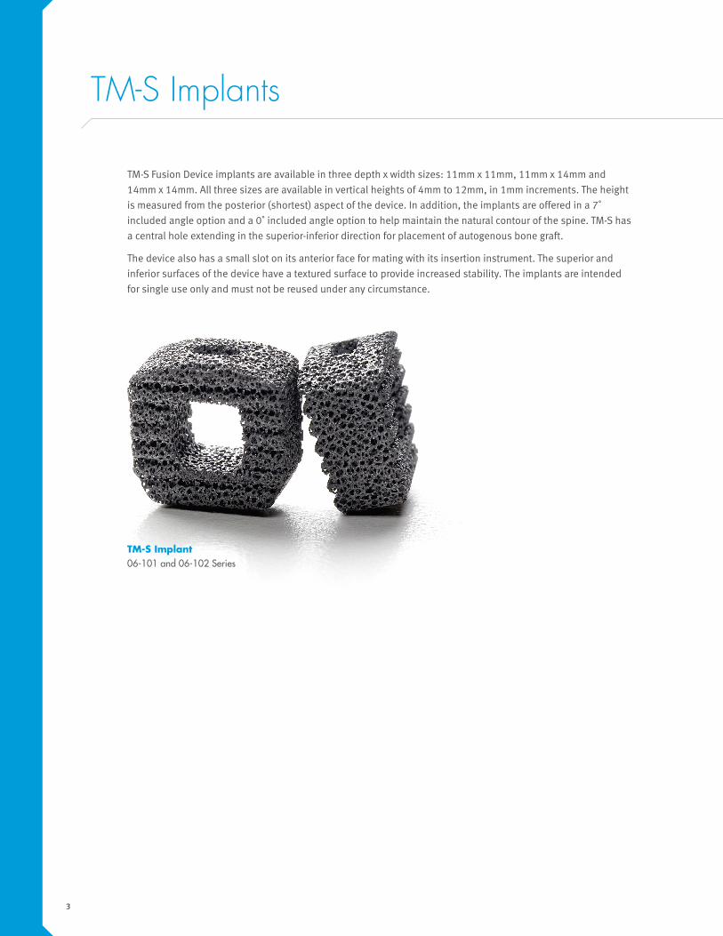
TM-S Fusion Device implants are available in three depth x width sizes: 11mm x 11mm, 11mm x 14mm and
14mm x 14mm. All three sizes are available in vertical heights of 4mm to 12mm, in 1mm increments. The height
is measured from the posterior (shortest) aspect of the device. In addition, the implants are offered in a 7˚
included angle option and a 0˚ included angle option to help maintain the natural contour of the spine. TM-S has
a central hole extending in the superior-inferior direction for placement of autogenous bone graft.
The device also has a small slot on its anterior face for mating with its insertion instrument. The superior and
inferior surfaces of the device have a textured surface to provide increased stability. The implants are intended
for single use only and must not be reused under any circumstance.
TM-S Implant 06-101 and 06-102 Series
TM-S Implants
4
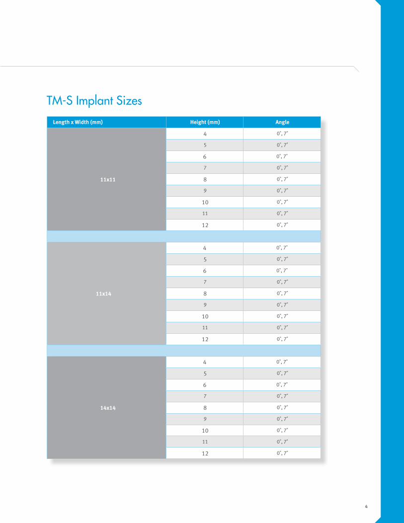
Length x Width (mm) Height (mm) Angle
11x11
4 0˚, 7˚
5 0˚, 7˚
6 0˚, 7˚
7 0˚, 7˚
8 0˚, 7˚
9 0˚, 7˚
10 0˚, 7˚
11 0˚, 7˚
12 0˚, 7˚
11x14
4 0˚, 7˚
5 0˚, 7˚
6 0˚, 7˚
7 0˚, 7˚
8 0˚, 7˚
9 0˚, 7˚
10 0˚, 7˚
11 0˚, 7˚
12 0˚, 7˚
14x14
4 0˚, 7˚
5 0˚, 7˚
6 0˚, 7˚
7 0˚, 7˚
8 0˚, 7˚
9 0˚, 7˚
10 0˚, 7˚
11 0˚, 7˚
12 0˚, 7˚
TM-S Implant Sizes
5
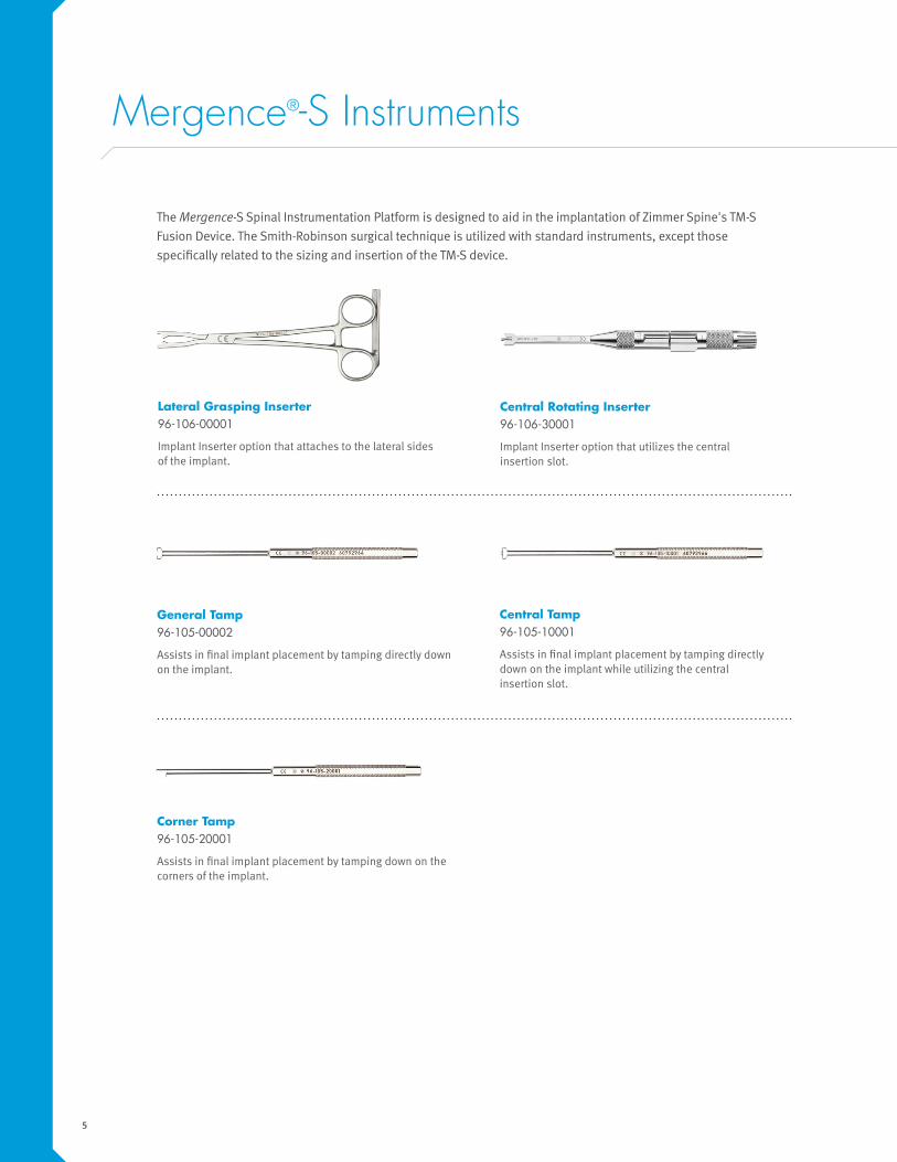
Mergence®-S Instruments
The Mergence-S Spinal Instrumentation Platform is designed to aid in the implantation of Zimmer Spine's TM-S
Fusion Device. The Smith-Robinson surgical technique is utilized with standard instruments, except those
specifically related to the sizing and insertion of the TM-S device.
Central Rotating Inserter 96-106-30001
Implant Inserter option that utilizes the central insertion slot.
Lateral Grasping Inserter 96-106-00001
Implant Inserter option that attaches to the lateral sides of the implant.
Corner Tamp 96-105-20001
Assists in final implant placement by tamping down on the corners of the implant.
Central Tamp 96-105-10001
Assists in final implant placement by tamping directly down on the implant while utilizing the central insertion slot.
General Tamp 96-105-00002
Assists in final implant placement by tamping directly down on the implant.

6
Provisionals and Rasps (14mm x 14mm, 7˚) 96-101-03041 to 96-101-03121 96-108-37041 to 96-108-37121
Assist in the measurement and preparation of the implant space.
Provisionals and Rasps (14mm x 14mm, 0˚) 96-102-03041 to 96-102-03121 96-108-30041 to 96-108-30121
Assist in the measurement and preparation of the implant space.
Provisionals and Rasps (11mm x 14mm, 0˚) 96-102-02041 to 96-102-02121 96-108-20041 to 96-108-20121
Assist in the measurement and preparation of the implant space.
Provisionals and Rasps (11mm x 11mm, 7˚) 96-101-01041 to 96-101-01121 96-108-17041 to 96-108-17121
Assist in the measurement and preparation of the implant space.
Provisionals and Rasps (11mm x 14mm, 7˚) 96-101-02041 to 96-101-02121 96-108-27041 to 96-108-27121
Assist in the measurement and preparation of the implant space.
Provisionals and Rasps (11mm x 11mm, 0˚) 96-102-01041 to 96-102-01121 96-108-10041 to 96-108-10121
Assist in the measurement and preparation of the implant space.
7
Surgical Technique
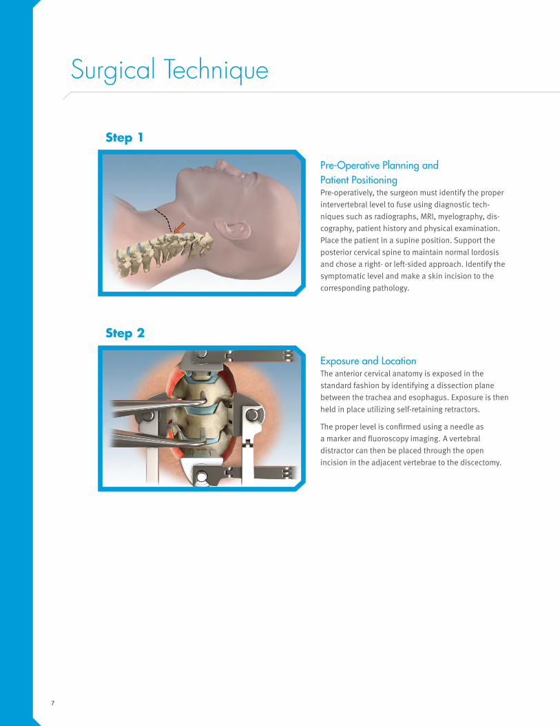
Pre-Operative Planning and Patient Positioning Pre-operatively, the surgeon must identify the proper
intervertebral level to fuse using diagnostic tech-
niques such as radiographs, MRI, myelography, dis-
cography, patient history and physical examination.
Place the patient in a supine position. Support the
posterior cervical spine to maintain normal lordosis
and chose a right- or left-sided approach. Identify the
symptomatic level and make a skin incision to the
corresponding pathology.
Step 1
Exposure and Location The anterior cervical anatomy is exposed in the
standard fashion by identifying a dissection plane
between the trachea and esophagus. Exposure is then
held in place utilizing self-retaining retractors.
The proper level is confirmed using a needle as
a marker and fluoroscopy imaging. A vertebral
distractor can then be placed through the open
incision in the adjacent vertebrae to the discectomy.
Step 2
8
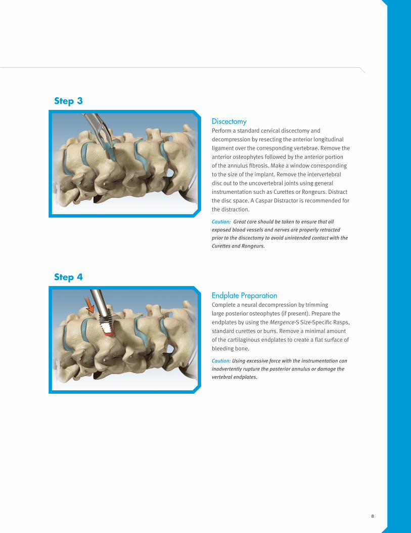
Endplate Preparation Complete a neural decompression by trimming
large posterior osteophytes (if present). Prepare the
endplates by using the Mergence-S Size-Specific Rasps,
standard curettes or burrs. Remove a minimal amount
of the cartilaginous endplates to create a flat surface of
bleeding bone.
Caution: Using excessive force with the instrumentation can inadvertently rupture the posterior annulus or damage the vertebral endplates.
Step 4
Discectomy Perform a standard cervical discectomy and
decompression by resecting the anterior longitudinal
ligament over the corresponding vertebrae. Remove the
anterior osteophytes followed by the anterior portion
of the annulus fibrosis. Make a window corresponding
to the size of the implant. Remove the intervertebral
disc out to the uncovertebral joints using general
instrumentation such as Curettes or Rongeurs. Distract
the disc space. A Caspar Distractor is recommended for
the distraction.
Caution: Great care should be taken to ensure that all exposed blood vessels and nerves are properly retracted prior to the discectomy to avoid unintended contact with the Curettes and Rongeurs.
Step 3
9
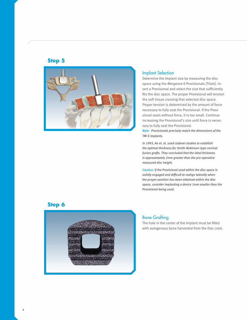
Implant Selection Determine the implant size by measuring the disc
space using the Mergence-S Provisionals (Trials). In-
sert a Provisional and select the size that sufficiently
fits the disc space. The proper Provisional will tension
the soft tissue crossing that selected disc space.
Proper tension is determined by the amount of force
necessary to fully seat the Provisional. If the Provi-
sional seats without force, it is too small. Continue
increasing the Provisional’s size until force is neces-
sary to fully seat the Provisional.Note: Provisionals precisely match the dimensions of the
TM-S implants.
In 1993, An et. al. used cadaver studies to establish the optimal thickness for Smith-Robinson-type cervical fusion grafts. They concluded that the ideal thickness is approximately 2mm greater than the pre-operative measured disc height.
Caution: If the Provisional used within the disc space is solidly engaged and difficult to realign laterally when the proper position has been obtained within the disc space, consider implanting a device 1mm smaller than the Provisional being used.
Step 5
Bone Grafting The hole in the center of the implant must be filled
with autogenous bone harvested from the iliac crest.
Step 6
10
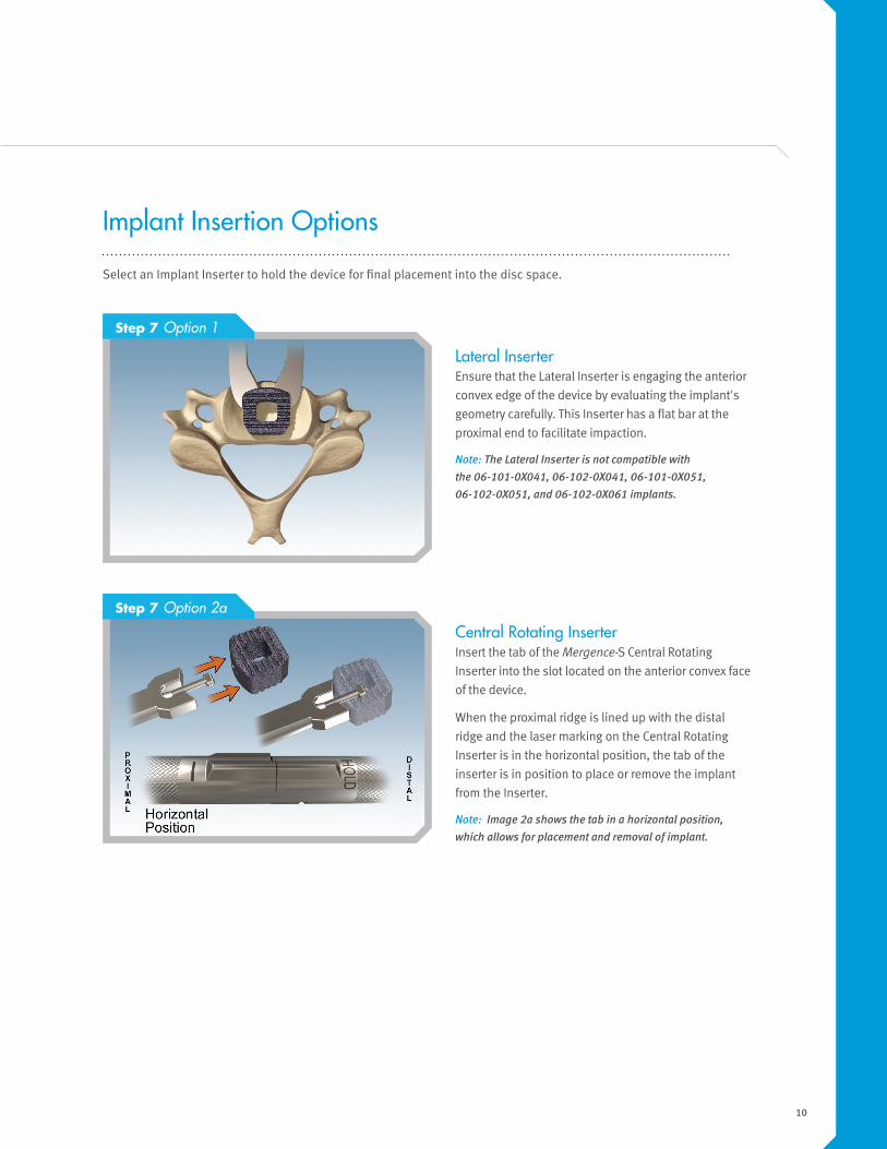
Lateral Inserter Ensure that the Lateral Inserter is engaging the anterior
convex edge of the device by evaluating the implant's
geometry carefully. This Inserter has a flat bar at the
proximal end to facilitate impaction.
Note: The Lateral Inserter is not compatible with the 06-101-0X041, 06-102-0X041, 06-101-0X051, 06-102-0X051, and 06-102-0X061 implants.
Step 7 Option 1
Step 7 Option 2a
Implant Insertion Options
Select an Implant Inserter to hold the device for final placement into the disc space.
Central Rotating Inserter Insert the tab of the Mergence-S Central Rotating
Inserter into the slot located on the anterior convex face
of the device.
When the proximal ridge is lined up with the distal
ridge and the laser marking on the Central Rotating
Inserter is in the horizontal position, the tab of the
inserter is in position to place or remove the implant
from the Inserter.
Note: Image 2a shows the tab in a horizontal position, which allows for placement and removal of implant.

11
Step 7 Option 2b
Inserter Positioning Hold the device onto the distal end of the Inserter. At
the same time, rotate the proximal end of the Inserter
clockwise until the vertical ridge is aligned with the
distal ridge.
When the proximal ridge is lined up with the distal
ridge and the laser marking is in the vertical position,
the tab is in position to secure the implant to the
Inserter.
Note: Image 2b shows the tab in a vertical position, which allows for securing the device onto the Inserter.
Securing Central Rotating Inserter Turn the knob clockwise until the device is secure on
the Inserter. The implant can be placed into the space
with the Inserter.
To remove the Inserter from the device, hold the
proximal end of the Inserter securely and turn the knob
counterclockwise until a stop is reached. Hold the distal
end of the Inserter, and at the same time, rotate the
proximal end counterclockwise until a stop is reached.
Pull the Inserter away from the implant while keeping
the Inserter parallel to the device.
Caution: Excessive force on the Inserter can damage the
instrument or the device.
Step 7 Option 2c
12
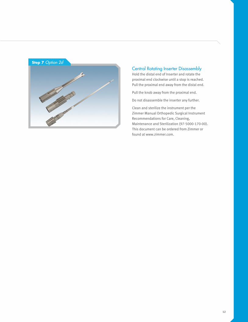
Central Rotating Inserter Disassembly Hold the distal end of Inserter and rotate the
proximal end clockwise until a stop is reached.
Pull the proximal end away from the distal end.
Pull the knob away from the proximal end.
Do not disassemble the inserter any further.
Clean and sterilize the instrument per the
Zimmer Manual Orthopedic Surgical Instrument
Recommendations for Care, Cleaning,
Maintenance and Sterilization (97-5000-170-00).
This document can be ordered from Zimmer or
found at www.zimmer.com.
Step 7 Option 2d
13
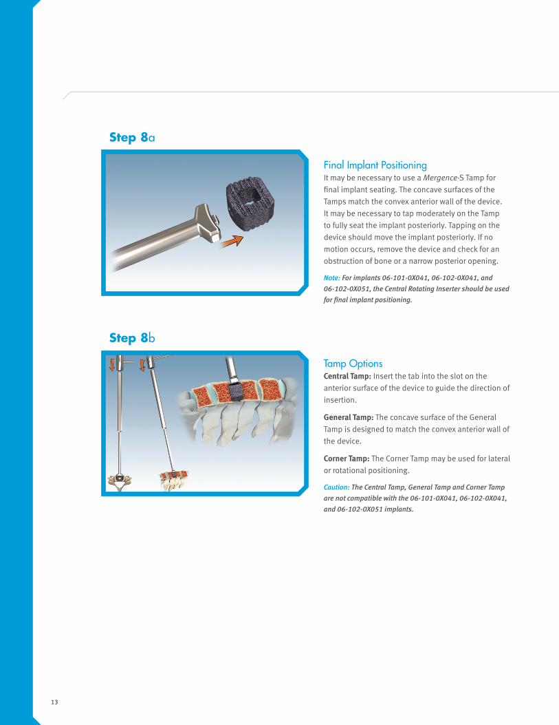
Final Implant Positioning It may be necessary to use a Mergence-S Tamp for
final implant seating. The concave surfaces of the
Tamps match the convex anterior wall of the device.
It may be necessary to tap moderately on the Tamp
to fully seat the implant posteriorly. Tapping on the
device should move the implant posteriorly. If no
motion occurs, remove the device and check for an
obstruction of bone or a narrow posterior opening.
Note: For implants 06-101-0X041, 06-102-0X041, and 06-102-0X051, the Central Rotating Inserter should be used for final implant positioning.
Step 8a
Tamp Options Central Tamp: Insert the tab into the slot on the
anterior surface of the device to guide the direction of
insertion.
General Tamp: The concave surface of the General
Tamp is designed to match the convex anterior wall of
the device.
Corner Tamp: The Corner Tamp may be used for lateral
or rotational positioning.
Caution: The Central Tamp, General Tamp and Corner Tamp are not compatible with the 06-101-0X041, 06-102-0X041, and 06-102-0X051 implants.
Step 8b
14
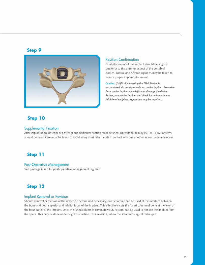
Position Confirmation Final placement of the implant should be slightly
posterior to the anterior aspect of the vertebral
bodies. Lateral and A/P radiographs may be taken to
assure proper implant placement.
Caution: If difficulty inserting the TM-S Device is encountered, do not vigorously tap on the implant. Excessive force on the implant may deform or damage the device. Rather, remove the implant and check for an impediment. Additional endplate preparation may be required.
Step 9
Supplemental FixationAfter implantation, anterior or posterior supplemental fixation must be used. Only titanium alloy (ASTM F-136) systems
should be used. Care must be taken to avoid using dissimilar metals in contact with one another as corrosion may occur.
Step 10
Post-Operative Management See package insert for post-operative management regimen.
Step 11
Implant Removal or Revision Should removal or revision of the device be determined necessary, an Osteotome can be used at the interface between
the bone and both superior and inferior faces of the implant. This effectively cuts the fused column of bone at the level of
the boundaries of the implant. Once the fused column is completely cut, Forceps can be used to remove the implant from
the space. This may be done under slight distraction. For a revision, follow the standard surgical technique.
Step 12
15
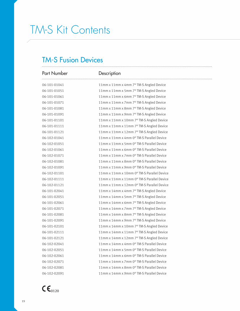
TM-S Kit Contents
Part Number Description
06-101-01041 11mm x 11mm x 4mm 7° TM-S Angled Device
06-101-01051 11mm x 11mm x 5mm 7° TM-S Angled Device
06-101-01061 11mm x 11mm x 6mm 7° TM-S Angled Device
06-101-01071 11mm x 11mm x 7mm 7° TM-S Angled Device
06-101-01081 11mm x 11mm x 8mm 7° TM-S Angled Device
06-101-01091 11mm x 11mm x 9mm 7° TM-S Angled Device
06-101-01101 11mm x 11mm x 10mm 7° TM-S Angled Device
06-101-01111 11mm x 11mm x 11mm 7° TM-S Angled Device
06-101-01121 11mm x 11mm x 12mm 7° TM-S Angled Device
06-102-01041 11mm x 11mm x 4mm 0° TM-S Parallel Device
06-102-01051 11mm x 11mm x 5mm 0° TM-S Parallel Device
06-102-01061 11mm x 11mm x 6mm 0° TM-S Parallel Device
06-102-01071 11mm x 11mm x 7mm 0° TM-S Parallel Device
06-102-01081 11mm x 11mm x 8mm 0° TM-S Parallel Device
06-102-01091 11mm x 11mm x 9mm 0° TM-S Parallel Device
06-102-01101 11mm x 11mm x 10mm 0° TM-S Parallel Device
06-102-01111 11mm x 11mm x 11mm 0° TM-S Parallel Device
06-102-01121 11mm x 11mm x 12mm 0° TM-S Parallel Device
06-101-02041 11mm x 14mm x 4mm 7° TM-S Angled Device
06-101-02051 11mm x 14mm x 5mm 7° TM-S Angled Device
06-101-02061 11mm x 14mm x 6mm 7° TM-S Angled Device
06-101-02071 11mm x 14mm x 7mm 7° TM-S Angled Device
06-101-02081 11mm x 14mm x 8mm 7° TM-S Angled Device
06-101-02091 11mm x 14mm x 9mm 7° TM-S Angled Device
06-101-02101 11mm x 14mm x 10mm 7° TM-S Angled Device
06-101-02111 11mm x 14mm x 11mm 7° TM-S Angled Device
06-101-02121 11mm x 14mm x 12mm 7° TM-S Angled Device
06-102-02041 11mm x 14mm x 4mm 0° TM-S Parallel Device
06-102-02051 11mm x 14mm x 5mm 0° TM-S Parallel Device
06-102-02061 11mm x 14mm x 6mm 0° TM-S Parallel Device
06-102-02071 11mm x 14mm x 7mm 0° TM-S Parallel Device
06-102-02081 11mm x 14mm x 8mm 0° TM-S Parallel Device
06-102-02091 11mm x 14mm x 9mm 0° TM-S Parallel Device
TM-S Fusion Devices
16
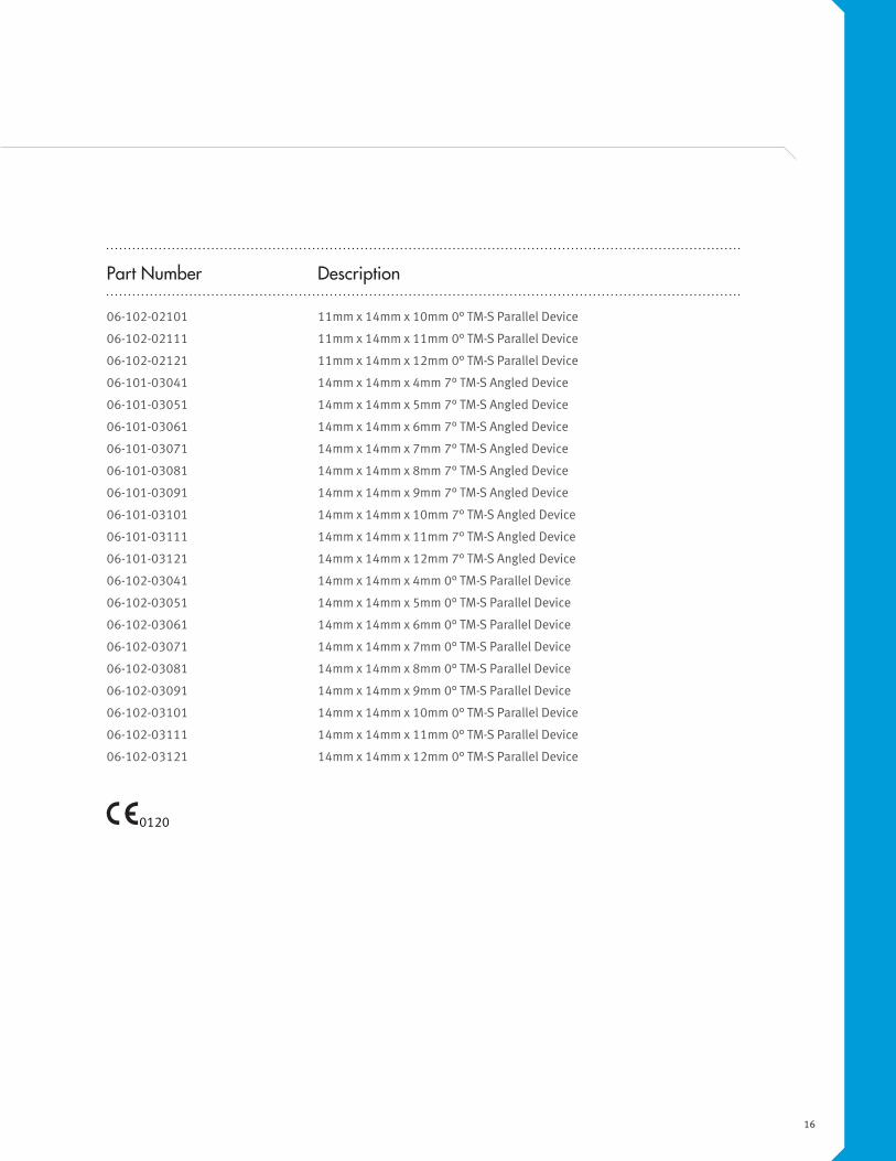
Part Number Description
06-102-02101 11mm x 14mm x 10mm 0° TM-S Parallel Device
06-102-02111 11mm x 14mm x 11mm 0° TM-S Parallel Device
06-102-02121 11mm x 14mm x 12mm 0° TM-S Parallel Device
06-101-03041 14mm x 14mm x 4mm 7° TM-S Angled Device
06-101-03051 14mm x 14mm x 5mm 7° TM-S Angled Device
06-101-03061 14mm x 14mm x 6mm 7° TM-S Angled Device
06-101-03071 14mm x 14mm x 7mm 7° TM-S Angled Device
06-101-03081 14mm x 14mm x 8mm 7° TM-S Angled Device
06-101-03091 14mm x 14mm x 9mm 7° TM-S Angled Device
06-101-03101 14mm x 14mm x 10mm 7° TM-S Angled Device
06-101-03111 14mm x 14mm x 11mm 7° TM-S Angled Device
06-101-03121 14mm x 14mm x 12mm 7° TM-S Angled Device
06-102-03041 14mm x 14mm x 4mm 0° TM-S Parallel Device
06-102-03051 14mm x 14mm x 5mm 0° TM-S Parallel Device
06-102-03061 14mm x 14mm x 6mm 0° TM-S Parallel Device
06-102-03071 14mm x 14mm x 7mm 0° TM-S Parallel Device
06-102-03081 14mm x 14mm x 8mm 0° TM-S Parallel Device
06-102-03091 14mm x 14mm x 9mm 0° TM-S Parallel Device
06-102-03101 14mm x 14mm x 10mm 0° TM-S Parallel Device
06-102-03111 14mm x 14mm x 11mm 0° TM-S Parallel Device
06-102-03121 14mm x 14mm x 12mm 0° TM-S Parallel Device
17
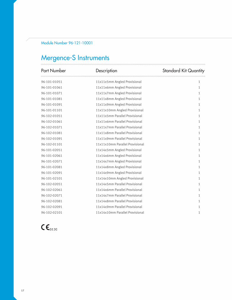
Module Number 96-121-10001
Part Number Description Standard Kit Quantity
96-101-01051 11x11x5mm Angled Provisional 1
96-101-01061 11x11x6mm Angled Provisional 1
96-101-01071 11x11x7mm Angled Provisional 1
96-101-01081 11x11x8mm Angled Provisional 1
96-101-01091 11x11x9mm Angled Provisional 1
96-101-01101 11x11x10mm Angled Provisional 1
96-102-01051 11x11x5mm Parallel Provisional 1
96-102-01061 11x11x6mm Parallel Provisional 1
96-102-01071 11x11x7mm Parallel Provisional 1
96-102-01081 11x11x8mm Parallel Provisional 1
96-102-01091 11x11x9mm Parallel Provisional 1
96-102-01101 11x11x10mm Parallel Provisional 1
96-101-02051 11x14x5mm Angled Provisional 1
96-101-02061 11x14x6mm Angled Provisional 1
96-101-02071 11x14x7mm Angled Provisional 1
96-101-02081 11x14x8mm Angled Provisional 1
96-101-02091 11x14x9mm Angled Provisional 1
96-101-02101 11x14x10mm Angled Provisional 1
96-102-02051 11x14x5mm Parallel Provisional 1
96-102-02061 11x14x6mm Parallel Provisional 1
96-102-02071 11x14x7mm Parallel Provisional 1
96-102-02081 11x14x8mm Parallel Provisional 1
96-102-02091 11x14x9mm Parallel Provisional 1
96-102-02101 11x14x10mm Parallel Provisional 1
Mergence-S Instruments

18
Part Number Description Standard Kit Quantity
96-106-30001 Central Rotating Inserter 1
96-106-00001 Lateral Grasping Inserter 1
07.00558.001 CSG Inserter 1
96-105-00002 General Tamp 1
96-105-10001 Central Tamp 1
96-105-20001 Corner Tamp 1
96-108-01001 11x11mm Starter Rasp 1
96-108-17051 11x11x5mm Angled Rasp 1
96-108-17061 11x11x6mm Angled Rasp 1
96-108-17071 11x11x7mm Angled Rasp 1
96-108-17081 11x11x8mm Angled Rasp 1
96-108-17091 11x11x9mm Angled Rasp 1
96-108-17101 11x11x10mm Angled Rasp 1
96-108-10051 11x11x5mm Parallel Rasp 1
96-108-10061 11x11x6mm Parallel Rasp 1
96-108-10071 11x11x7mm Parallel Rasp 1
96-108-10081 11x11x8mm Parallel Rasp 1
96-108-10091 11x11x9mm Parallel Rasp 1
96-108-10101 11x11x10mm Parallel Rasp 1
96-108-02001 11x14mm Starter Rasp 1
96-108-27051 11x14x5mm Angled Rasp 1
96-108-27061 11x14x6mm Angled Rasp 1
96-108-27071 11x14x7mm Angled Rasp 1
96-108-27081 11x14x8mm Angled Rasp 1
96-108-27091 11x14x9mm Angled Rasp 1
96-108-27101 11x14x10mm Angled Rasp 1
96-108-20051 11x14x5mm Parallel Rasp 1
96-108-20061 11x14x6mm Parallel Rasp 1
96-108-20071 11x14x7mm Parallel Rasp 1
96-108-20081 11x14x8mm Parallel Rasp 1
96-108-20091 11x14x9mm Parallel Rasp 1
96-108-20101 11x14x10mm Parallel Rasp 1

19
Module Number 96-261-20001
Part Number Description Standard Kit Quantity
96-108-03001 14x14mm Starter Rasp 1
96-108-37051 14x14x5mm Angled Rasp 1
96-108-37061 14x14x6mm Angled Rasp 1
96-108-37071 14x14x7mm Angled Rasp 1
96-108-37081 14x14x8mm Angled Rasp 1
96-108-37091 14x14x9mm Angled Rasp 1
96-108-37101 14x14x10mm Angled Rasp 1
96-108-30051 14x14x5mm Parallel Rasp 1
96-108-30061 14x14x6mm Parallel Rasp 1
96-108-30071 14x14x7mm Parallel Rasp 1
96-108-30081 14x14x8mm Parallel Rasp 1
96-108-30091 14x14x9mm Parallel Rasp 1
96-108-30101 14x14x10mm Parallel Rasp 1
Part Number Description Standard Kit Quantity
96-101-03051 14x14x5mm Angled Provisional 1
96-101-03061 14x14x6mm Angled Provisional 1
96-101-03071 14x14x7mm Angled Provisional 1
96-101-03081 14x14x8mm Angled Provisional 1
96-101-03091 14x14x9mm Angled Provisional 1
96-101-03101 14x14x10mm Angled Provisional 1
96-102-03051 14x14x5mm Parallel Provisional 1
96-102-03061 14x14x6mm Parallel Provisional 1
96-102-03071 14x14x7mm Parallel Provisional 1
96-102-03081 14x14x8mm Parallel Provisional 1
96-102-03091 14x14x9mm Parallel Provisional 1
96-102-03101 14x14x10mm Parallel Provisional 1
Mergence-S Instruments: 14x14mm
20
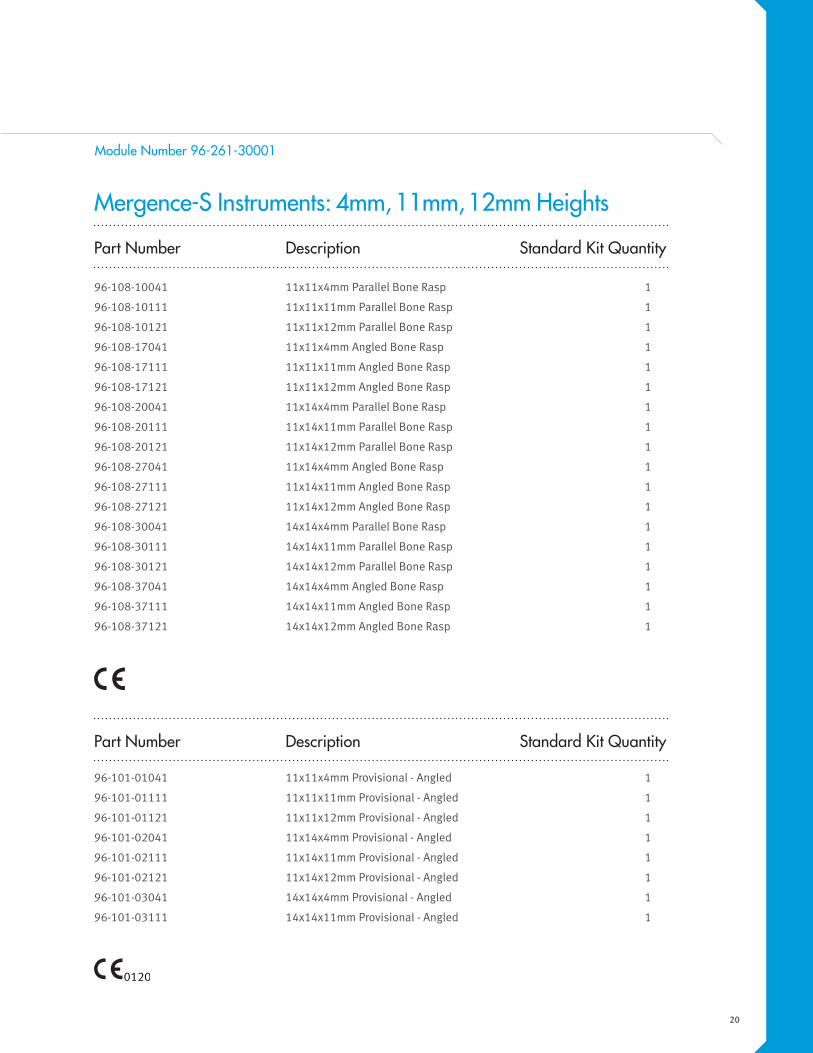
Part Number Description Standard Kit Quantity
96-108-10041 11x11x4mm Parallel Bone Rasp 1
96-108-10111 11x11x11mm Parallel Bone Rasp 1
96-108-10121 11x11x12mm Parallel Bone Rasp 1
96-108-17041 11x11x4mm Angled Bone Rasp 1
96-108-17111 11x11x11mm Angled Bone Rasp 1
96-108-17121 11x11x12mm Angled Bone Rasp 1
96-108-20041 11x14x4mm Parallel Bone Rasp 1
96-108-20111 11x14x11mm Parallel Bone Rasp 1
96-108-20121 11x14x12mm Parallel Bone Rasp 1
96-108-27041 11x14x4mm Angled Bone Rasp 1
96-108-27111 11x14x11mm Angled Bone Rasp 1
96-108-27121 11x14x12mm Angled Bone Rasp 1
96-108-30041 14x14x4mm Parallel Bone Rasp 1
96-108-30111 14x14x11mm Parallel Bone Rasp 1
96-108-30121 14x14x12mm Parallel Bone Rasp 1
96-108-37041 14x14x4mm Angled Bone Rasp 1
96-108-37111 14x14x11mm Angled Bone Rasp 1
96-108-37121 14x14x12mm Angled Bone Rasp 1
Part Number Description Standard Kit Quantity
96-101-01041 11x11x4mm Provisional - Angled 1
96-101-01111 11x11x11mm Provisional - Angled 1
96-101-01121 11x11x12mm Provisional - Angled 1
96-101-02041 11x14x4mm Provisional - Angled 1
96-101-02111 11x14x11mm Provisional - Angled 1
96-101-02121 11x14x12mm Provisional - Angled 1
96-101-03041 14x14x4mm Provisional - Angled 1
96-101-03111 14x14x11mm Provisional - Angled 1
Module Number 96-261-30001
Mergence-S Instruments: 4mm, 11mm, 12mm Heights
21
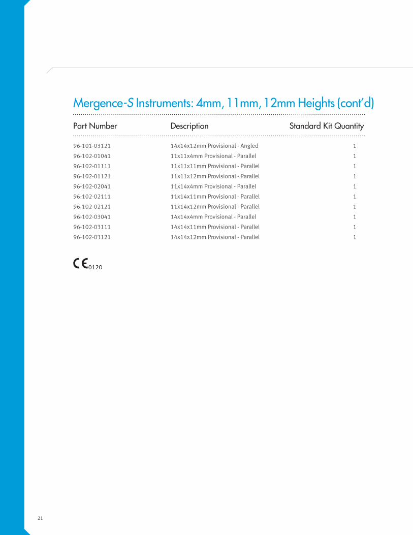
Part Number Description Standard Kit Quantity
96-101-03121 14x14x12mm Provisional - Angled 1
96-102-01041 11x11x4mm Provisional - Parallel 1
96-102-01111 11x11x11mm Provisional - Parallel 1
96-102-01121 11x11x12mm Provisional - Parallel 1
96-102-02041 11x14x4mm Provisional - Parallel 1
96-102-02111 11x14x11mm Provisional - Parallel 1
96-102-02121 11x14x12mm Provisional - Parallel 1
96-102-03041 14x14x4mm Provisional - Parallel 1
96-102-03111 14x14x11mm Provisional - Parallel 1
96-102-03121 14x14x12mm Provisional - Parallel 1
Mergence-S Instruments: 4mm, 11mm, 12mm Heights (cont’d)
22
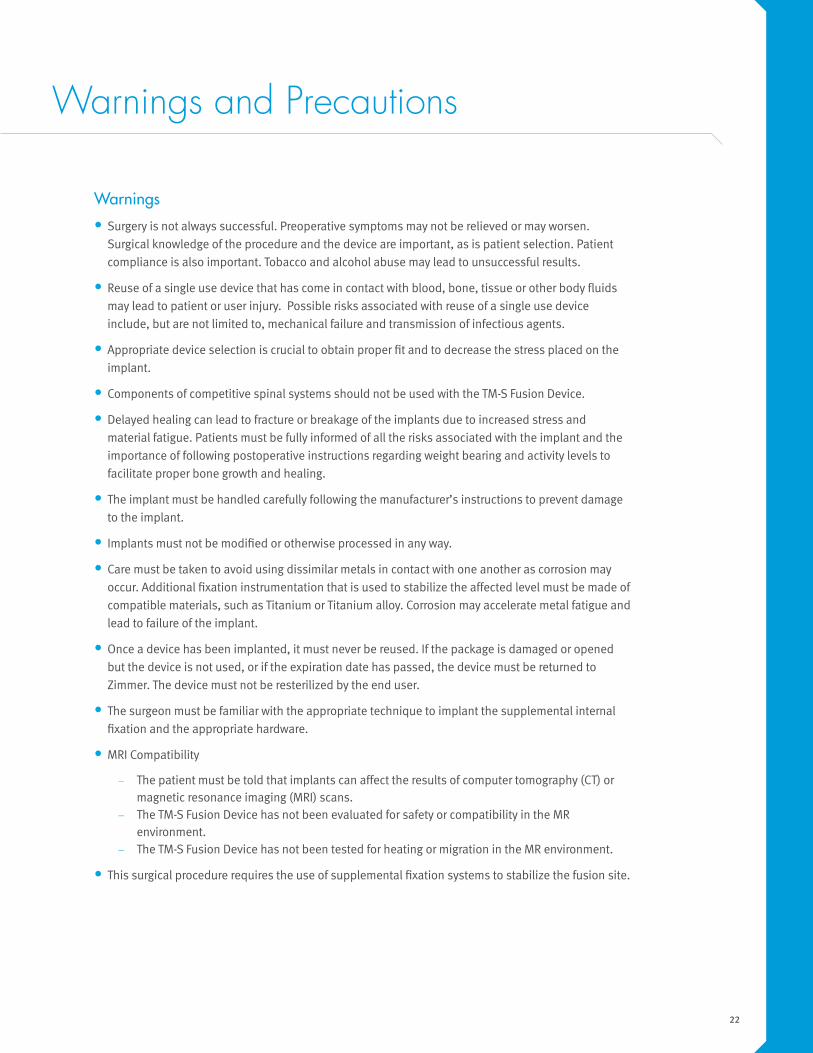
Warnings and Precautions
Warnings
• Surgery is not always successful. Preoperative symptoms may not be relieved or may worsen.
Surgical knowledge of the procedure and the device are important, as is patient selection. Patient
compliance is also important. Tobacco and alcohol abuse may lead to unsuccessful results.
• Reuse of a single use device that has come in contact with blood, bone, tissue or other body fluids
may lead to patient or user injury. Possible risks associated with reuse of a single use device
include, but are not limited to, mechanical failure and transmission of infectious agents.
• Appropriate device selection is crucial to obtain proper fit and to decrease the stress placed on the
implant.
• Components of competitive spinal systems should not be used with the TM-S Fusion Device.
• Delayed healing can lead to fracture or breakage of the implants due to increased stress and
material fatigue. Patients must be fully informed of all the risks associated with the implant and the
importance of following postoperative instructions regarding weight bearing and activity levels to
facilitate proper bone growth and healing.
• The implant must be handled carefully following the manufacturer’s instructions to prevent damage
to the implant.
• Implants must not be modified or otherwise processed in any way.
• Care must be taken to avoid using dissimilar metals in contact with one another as corrosion may
occur. Additional fixation instrumentation that is used to stabilize the affected level must be made of
compatible materials, such as Titanium or Titanium alloy. Corrosion may accelerate metal fatigue and
lead to failure of the implant.
• Once a device has been implanted, it must never be reused. If the package is damaged or opened
but the device is not used, or if the expiration date has passed, the device must be returned to
Zimmer. The device must not be resterilized by the end user.
• The surgeon must be familiar with the appropriate technique to implant the supplemental internal
fixation and the appropriate hardware.
• MRI Compatibility
— The patient must be told that implants can affect the results of computer tomography (CT) or magnetic resonance imaging (MRI) scans.
— The TM-S Fusion Device has not been evaluated for safety or compatibility in the MR environment.
— The TM-S Fusion Device has not been tested for heating or migration in the MR environment.
• This surgical procedure requires the use of supplemental fixation systems to stabilize the fusion site.
23
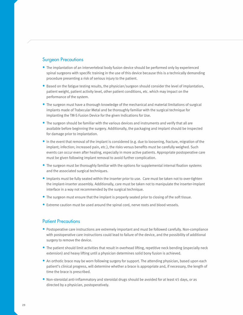
Surgeon Precautions
• The implantation of an intervertebral body fusion device should be performed only by experienced
spinal surgeons with specific training in the use of this device because this is a technically demanding
procedure presenting a risk of serious injury to the patient.
• Based on the fatigue testing results, the physician/surgeon should consider the level of implantation,
patient weight, patient activity level, other patient conditions, etc. which may impact on the
performance of the system.
• The surgeon must have a thorough knowledge of the mechanical and material limitations of surgical
implants made of Trabecular Metal and be thoroughly familiar with the surgical technique for
implanting the TM-S Fusion Device for the given Indications for Use.
• The surgeon should be familiar with the various devices and instruments and verify that all are
available before beginning the surgery. Additionally, the packaging and implant should be inspected
for damage prior to implantation.
• In the event that removal of the implant is considered (e.g. due to loosening, fracture, migration of the
implant; infection; increased pain, etc.), the risks versus benefits must be carefully weighed. Such
events can occur even after healing, especially in more active patients. Appropriate postoperative care
must be given following implant removal to avoid further complication.
• The surgeon must be thoroughly familiar with the options for supplemental internal fixation systems
and the associated surgical techniques.
• Implants must be fully seated within the inserter prior to use. Care must be taken not to over-tighten
the implant-inserter assembly. Additionally, care must be taken not to manipulate the inserter-implant
interface in a way not recommended by the surgical technique.
• The surgeon must ensure that the implant is properly seated prior to closing of the soft tissue.
• Extreme caution must be used around the spinal cord, nerve roots and blood vessels.
Patient Precautions
• Postoperative care instructions are extremely important and must be followed carefully. Non-compliance
with postoperative care instructions could lead to failure of the device, and the possibility of additional
surgery to remove the device.
• The patient should limit activities that result in overhead lifting, repetitive neck bending (especially neck
extension) and heavy lifting until a physician determines solid bony fusion is achieved.
• An orthotic brace may be worn following surgery for support. The attending physician, based upon each
patient’s clinical progress, will determine whether a brace is appropriate and, if necessary, the length of
time the brace is prescribed.
• Non-steroidal anti-inflammatory and steroidal drugs should be avoided for at least 45 days, or as
directed by a physician, postoperatively.


Manufactured by:
Zimmer TMT10 Pomeroy RoadParsippany, NJ 07054201.818.1800
Distributed by:
Zimmer Spine7375 Bush Lake RoadMinneapolis, MN 55439800.655.2614
zimmerspine.com
L1569 Rev. D (2015-05)(851S-1001-00) © 2015 Zimmer Spine, Inc.
LIP-4
5 Re
v. D
Disclaimer:
This documentation is intended exclusively for physicians and is not intended for laypersons. Information on the products and procedures contained in this document is of a general nature and does not represent and does not constitute medical advice or recommendations. Because this information does not purport to constitute any diagnostic or therapeutic statement with regard to any individual medical case, each patient must be examined and advised individually, and this document does not replace the need for such examination and/or advice in whole or in part. Please refer to the package inserts for important product information, including, but not limited to, indications, contraindications, warnings, precautions, and adverse effects.
Caution: Federal (USA) law restricts this device to sale by or on the order of a physician. Please see the product Instructions for Use for a complete listing of the indications, contraindications, warnings, precautions and adverse effects.