TM INSTALLATION INSTRUCTIONS
51
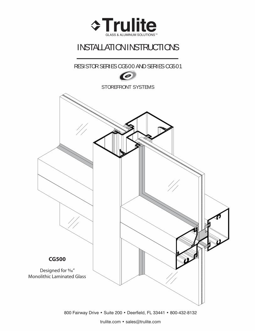
800 Fairway Drive • Suite 200 • Deerfield, FL 33441 • 800-432-8132 trulite.com • [email protected] CG500 TM INSTALLATION INSTRUCTIONS RESISTOR SERIES CG500 AND SERIES CG501 STOREFRONT SYSTEMS Designed for 9⁄16” Monolithic Laminated Glass
Transcript of TM INSTALLATION INSTRUCTIONS
800 Fairway Drive • Suite 200 • Deerfield, FL 33441 • 800-432-8132
trulite.com • [email protected]
CG500
TM
INSTALLATION INSTRUCTIONS
RESISTOR SERIES CG500 AND SERIES CG501
S T O R E F R O N T S Y S T E M S
Designed for 9⁄16” Monolithic Laminated Glass
TM
SERIES CG500 and CG501
PANEL-SETINSTALLATION INSTRUCTIONS
Page 2 trulite.com Eff ective August, 2012
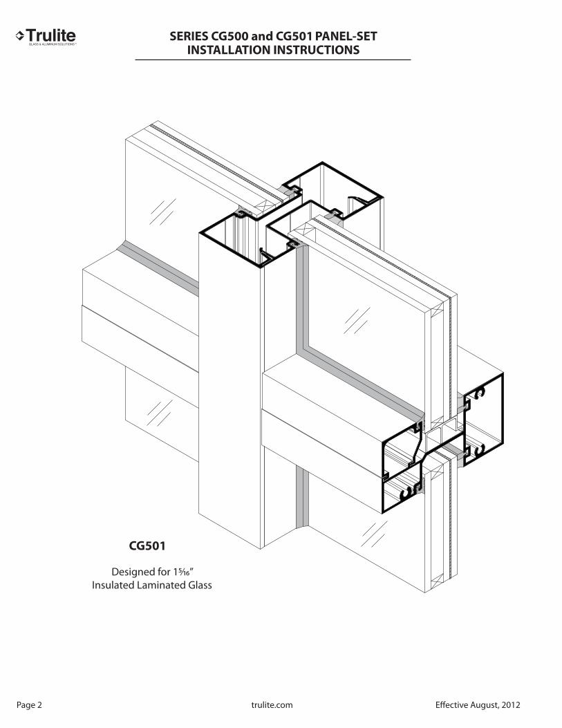
CG501
Designed for 15⁄16” Insulated Laminated Glass

TM
SERIES CG500 and CG501
PANEL-SETINSTALLATION INSTRUCTIONS
Eff ective August, 2012 trulite.com Page 3
CG500
AND CG501 TABLE OF CONTENTS
INSTALLATION INSTRUCTION NOTES
PART 1 Handling, Storage and Protection of Aluminum ................................................................................................................... PART 2 General Installation Instructions ................................................................................................................................................ Product Application Selection & Installation ........................................................................................................................................
M-PACT SAFE ENTRANCE DOORS
Options and Limitations ............................................................................................................................................................................... Hardware Locations ........................................................................................................................................................................................ Typical Details Series 256 for Wet Glazed Applications ...................................................................................................................... Typicall Details - Series 256 for Dry Glazed Applications .................................................................................................................. Typical Details Series 356 for Wet Glazed Applications ..................................................................................................................... Typical Details - Series 356 for Dry Glazed Applications ...................................................................................................................
M-PACT SAFE CG500S/CG501S Storefront Systems
Pictoral View................................................................................................................................................................................................... CG500 Accessories .......................................................................................................................................................................................... CG501S2 Accessories ....................................................................................................................................................................................... CG500S2 Options and Limitations ............................................................................................................................................................. CG500S2 Typical Details for Wet Glazed Applications ......................................................................................................................... CG500S2 Typical Details for Dry Glazed Applications ......................................................................................................................... CG500S2 Options and Limitations ............................................................................................................................................................. CG500S2 Typical Details for Wet Glazed Applications ........................................................................................................................ CG500S2 Typical Details for Dry Glazed Applications .........................................................................................................................
FRAME FABRICATION
Determine Frame Size .................................................................................................................................................................................... Fabricate Verticals and Pocket Fillers for Spline Screws ..................................................................................................................... Steel Reinforcement ........................................................................................................................................................................................ Head/Sill .............................................................................................................................................................................................................. Wall Jamb ........................................................................................................................................................................................................... Subsill Flashing ................................................................................................................................................................................................
FRAME ASSEMBLY
GT-1 Tacky Tape Application ....................................................................................................................................................................... Vertical to Horizontal Joinery ...................................................................................................................................................................... INSTALLATION
Sill Flashing Installation.................................................................................................................................................................................. Sill Flashing at Doorjamb .............................................................................................................................................................................. Sill Flashing Splice ............................................................................................................................................................................................ Panel Sequencing............................................................................................................................................................................................. Panel-Set Frame Attachment to Substrate .............................................................................................................................................
GLAZING
Glazing and Gasket Preparation Instructions ....................................................................................................................................... Installing Glass, Water Diverters and Gasket......................................................................................................................................... Sealant at Interior Gasket Corners.............................................................................................................................................................. Glass Size Formulas.......................................................................................................................................................................................... Transom Glass Size Formulas .......................................................................................................................................................................
ANCHOR CHARTS/PERIMETER FASTENER LOCATIONS
Typical Attachment to Wood/Steel/Concrete Substrate ...................................................................................................................
44-5
6
78
9-1011-1213-1415-16
171819202122232425
262728293031
3233
3435353637
3839-40
4142
43-44
45-50

TM
SERIES CG500 and CG501
PANEL-SETINSTALLATION INSTRUCTIONS
Page 4 trulite.com Eff ective August, 2012
PART 1-Handling, Storing and Protection of Aluminum
A. PRECAUTIONS: The following precautions are recommended to protect architectural aluminum materials against damage. Following these precautions will help ensure early acceptance of your products and workmanship.
B. HANDLE CAREFULLY: All aluminum materials stored at job site must be stored with adequate separation and not stacked directly onto the concrete fl oor slab to prevent materials from being damaged when handling. Cardboard wrapped or paper interleaved materials must be kept dry.
C. CHECK ARRIVING MATERIALS: Check for quantity and keep records of where various materials are stored.
D. KEEP MATERIAL AWAY FROM WATER, MUD AND SPRAY: Prevent cement, plaster or other materials from damaging the fi nish.
E. PROTECT MATERIALS AFTER ERECTION: Wrap aluminum section profi les with polyethylene or protect by erecting a polyethylene splatter screen. Cement, plaster, terrazzo, other alkaline solutions and acid based materials used to clean masonry are very harmful to the fi nish and should be removed with water and mild soap IMMEDIATELY. Reference AAMA 609 and 610-2 for cleaning architectural aluminum.
PART 2- General Installation Instructions
A. CHECK SHOP DRAWINGS, INSTALLATION INSTRUCTIONS AND GLAZING INSTRUCTIONS to become thoroughly familiar with the project. The SHOP DRAWINGS take precedence and include specifi c details for the project. The INSTALLATION INSTRUCTIONS are of general nature and cover most common conditions.
B. CUTTING TOLERANCES: Fabrication cutting tolerances are plus zero (0”) minus one thirty second (1/32”) unless otherwise noted.
C. ERECTION: All materials are to be installed plumb, level and true.
D. BENCH MARKS: All work should start from bench marks and/or column lines established by the ARCHITECTURAL
DRAWINGS and the GENERAL CONTRACTOR with guaranteed accuracy. Working from these datum points and lines determine: a) The plane of the wall in relation to off set lines provided on each fl oor. b) The fi nish fl oor lines in relation to bench marks on the outer building columns. c) Mullion spacing from both ends of masonry opening to prevent dimensional build-up of daylight openings.
E. STEEL ANCHORS. Steel anchors that weld to steel structure are normally line set before mullions are hung. Outstanding leg of anchors must be at 90º to off set lines. Mullion space should be held to ±1/32”. Steel anchors vary per job conditions. Follow approved shop drawings for size and location of steel anchors.
F. FIELD WELDING. All fi eld welding must be adequately shielded to avoid any splatter on glass or aluminum. Results will be unsightly and/or structurally unsound. Advise general contractor and other trades accordingly. All fi eld welds of steel anchors must receive touch-up paint (zinc chromate) to avoid rust. G. ISOLATION OF ALUMINUM: Aluminum to be placed in direct contact with uncured masonry or incompatible materials should be isolated with a heavy coat of zinc chromate or bituminous paint.

TM
SERIES CG500 and CG501
PANEL-SETINSTALLATION INSTRUCTIONS
Eff ective August, 2012 trulite.com Page 5
H. SEALANTS: Sealants must be compatible with all materials which they have contact, including other sealant surfaces. Consult with sealant manufacturer for recommendations relative to joint size, shelf life, compatibility, cleaning/priming, tooling, adhesion, etc. It is the responsibility of the GLAZING CONTRACTOR to submit a statement from the sealant manufacturer indicating that glass and glazing materials have been tested for compatibility and adhesion with glazing sealants, and interpreting test results relative to material performance, including recommendations for primers and substrate preparation required to obtain adhesion. The chemical compatibility of all glazing materials and framing sealants with each other and with like materials used in glass fabrication must be established. This is required on every project.
I. FASTENING: Within the body of these instructions, “fastening” means any method of securing one part to another or to adjacent materials. Only those fasteners used for system assembly are specifi ed in these instructions. Due to various substrates to which the framing may be attached, structural perimeter anchor fasteners are not specifi ed in these instructions. For structural perimeter fasteners, reference the shop drawings, structural anchor charts or consult with the fastener supplier.
J. BUILDING CODES: Glass and glazing codes governing the design and use of products vary widely throughout the USA. Trulite does not control the selection of product confi gurations, operating hardware, or glazing materials, and assumes no responsibility for these design considerations. It is the responsibility of the owner, specifi er, architect, general contractor and installer to make these selections in strict conformance with all applicable codes.
K. FIELD TESTING: It is recommended that AAMA 501.2 Water Hose Test be conducted once a suffi cient portion of the framing is installed, glazed and sealed to ensure proper installation. This test should be repeated on large projects at specifi c intervals as deemed necessary by job conditions and acceptability quality control standards.
L. COORDINATION WITH OTHER TRADES: Coordinate with the GENERAL CONTRACTOR and sequence with other trades any materials which off set your framing installation. For example, backup walls, partitions, ceilings, mechanical ducts, convectors, etc.
M. FINAL CLEANING (CARE AND MAINTENANCE): Final cleaning of exposed aluminum surfaces should be done in accordance with AAMA publications 609.1 for anodized aluminum and 610.1 for applied painted coatings (liquid or powder).
N. PRODUCT DESIGN CHANGES: Trulite reserves the right to make product design changes without prior notice when deemed necessary for product improvement. Please check website at www.trulite.com for the latest product installation instruction manual prior to commencing work. Reference the Options
and Limitation Chart shown in the Trulite Architectural Manual for glass types and sizes qualifi ed
for use with this system.
PRODUCT APPLICATION AND INSTALLATION
Series CG500 and CG501 Storefront systems are designed for simple screw spline fabrication and Panel-Set installation.Impact Glazing framing installation should be limited to glazing contractors employing project management and fi eld person-nel experienced in handling this type work. CAUTION: Glass and mullions function as an integral unit and cannot be altered without sacrifi cing the integrity of the system.
CG500 and CG501 Storefront requires the installer to pay close attention to the details shown within these InstallationInstructions. Critical seals must be done as shown.
Trulite Abbreviations used in these instructions:
C.O.C. = Concealed Overhead Closer D.L.O. = Day Light Opening DG = Dry Glazed S.A.C. = Surface Applied Closer C.V.R. = Concealed Vertical Rod WG = Wet Glazed D.O.W. = Door Opening Width 0 = Diameter D.O.H. = Door Opening Height Typ. = Typical B.G. = Structual Silicone Glazing

TM
SERIES CG500 and CG501
PANEL-SETINSTALLATION INSTRUCTIONS
Page 6 trulite.com Eff ective August, 2012
PRODUCT APPLICATION SELECTION AND INSTALLATION
Trulite hurricane - impact resistant storefront systems were especially designed with screw spline join-ery for simple fabrication and Panel-Set installation. These systems should only be installed by glazing contractors employing personnel with the necessary installation and project management experience to handle hurricane impact glazing.
Hurricane Impact-resistant storefront systems require the installer to pay close attention to the details shown within these instructions and general notes. All critical seal areas must be done as shown.
CAUTION
HURRICANE IMPACT GLASS AND MULLION COMBINATIONS FUNCTION AS AN INTEGRAL UNIT. THE COMBINATIONS SHOWN IN THE OPTIONS AND LIMITATIONS CHARTS ARE BASED ON ACTUAL PERFORMANCE TESTING AND MAY NOT BE ALTERED WITHOUT SACRIFICING THE INTEGRITY OF THE SYSTEMS.

TM
SERIES CG500 and CG501
PANEL-SETINSTALLATION INSTRUCTIONS
Eff ective August, 2012 trulite.com Page 7
RESISTOR ENTRANCE DOORS
SERIES 256, 356 DOORS
FEATURES AND OPTIONS
DOORS MAY BE WET GLAZED OR DRY GLAZED
Series 256 and 356 Resistor doors have successfully passed the stringent Florida Building Code TAS 201 and ASTM E 1886/1996 for large missile Hurricane Impact Resistance. These doors were designed for installation into Trulite Resistor storefront and curtain wall framing systems.
Resistor Entrance Doors
Door
Series
Stile Stile Width
(inches)
Top Rail
(inches)
Bottom Rail
(inches)
ADA Bottom
Rail Option
(inches)
256 Narrow 2-1/8 2-1/4 4 9-1/2
356 Medium 3-3/4 4 7 9-1/2
OPTIONS AND LIMITATIONS
Series 256 Narrow Stile Doors with DF500 Doorframes
Design
Pressure
Maximum Door
Opening Size
Maximum Glass Size Qualifi ed Glass Types
+/- 65 P.S.F.Single Pair D.L.O. (W x H) Wet Glazed Dry Glazed
36” x 84” 72” x 84” 31-1/8” x 76-1/2” 17.8 Ft.2 B A
OPTIONS AND LIMITATIONS
Series 356 Narrow Stile Doors with DF500 Doorframes
Design
Pressure
Maximum Door
Opening Size
Maximum Glass Size Qualifi ed Glass Types
+/- 70 P.S.F.Single Pair D.L.O. (W x H) Wet Glazed Dry Glazed
42” x 96” 84” x 96” 33-7/8” x 83-3/4” 19.7 Ft.2 B A
Thickness Glass Composition Manufacturer Glass Types
9/16” Laminated Glass Consisting of two 1/4” HS Lites with .090 Sentry Glas Interlayer NOA # 07-1116.04
DuPont A
9/16” Laminated Glass Consisting of two 1/4” HS Lites with .090 Butacite P.V.B. Interlayer NOA # 05-1208.02
DuPont B

TM
SERIES CG500 and CG501
PANEL-SETINSTALLATION INSTRUCTIONS
9¼
9¼Eq
uidi
stan
tEq
uidi
stan
t58
15⁄16
Max
imum
Hei
ght
377⁄8
C Cy
linde
r
385⁄3
2C
Exit
423⁄8
C To
p of
Pul
l
Bottom of Door
Panic exit applications require a Series 2086 Jackson CVR ANSI Grade 1.
HARDWARE LOCATIONS FOR IMPACT RESISTANT DOORS
L
L
L
34C
Cylin
der
37¾
C Pu
sh B
ar
Bottom of Door
L L
121⁄8
Flush Bolts( 2 each)
MAXIMUM DOW DOH
SERIES 256 72 84
SERIES 356 84 96
LC
LC
LC
LC
LC
(inches)
Top of Door
Page 8 trulite.com Eff ective August, 2012
HARDWARE LOCATIONS FOR IMPACT- RESISTANT DOORS
(INCHES)
Resistor Entrance Doors require 1½ pair butt hinges and 3-point lock
Resistor Entrance DoorsDOOR CLOSERS
Surface:
Heavy Duty ANSI
Grade 1
Concealed Overhead:
ANSI Grade 1

TM
SERIES CG500 and CG501
PANEL-SETINSTALLATION INSTRUCTIONS
Eff ective August, 2012 trulite.com Page 9
DF108-2
DR105/RG-10
TH450
DR400
5”
3⁄16”
½”
DF500-2
2½”
3¼”
5”
DF111
DF110
DR225
¼”
1⁄8”
DF108-2
DR215 DR214
DR103
DR104
31⁄8”31⁄8”3⁄16”
RG-1
1 1
3
4
2
5
6
SCALE 3” = 1’-0“
1 2 3 4 2
55
6 6
SERIES 256 DOORS FOR WET GLAZED APPLICATIONS
DF500-2
2½”
5”
DF102
DR400
¼”
1⁄8”
5
Concealed Overhead Closer and Offset Arm
A
Frame T-Bar for SAC (Surface Applied Closer)
31⁄8”
DF500-1
DR213
2½”3⁄32”
CG500-5
ST500-1
RG-1
2½”31⁄8” ¼”3⁄32”
DF500-1
DR213
SW700-18
DF110
DF111
31⁄8”
DF500-1
2½”
CG500-5
ST500-1 DR213
DF111
DF110
3⁄32”
For Optional Bottom Rails,See Page 4.
31⁄8”
DF500-1
DR213
2½”3⁄32”
CG501-5
ST500-1
A
B B B
SB-18
DR-105/RG-10 required for all doors to meet air infiltration testing.
Reference Page 7 for glass types qualified for doors

TM
SERIES CG500 and CG501
PANEL-SETINSTALLATION INSTRUCTIONS
Page 10 trulite.com Eff ective August, 2012
2½” ¼”1”
DF107
DF106
DF500-1
SW700-18
2½” 1”
DF107
DF106CG500-5
ST500-1
DF500-1
RG-13
DF500-2
2½”
1”3¼
”
DF111
DF110
DR225
1⁄8”
DF107 DF106
2½”
5”
CG500-11
¼”
DF500-2
2½”
1”5”
DF102
DR400
1⁄8”
DF107 DF106
1 2
3
4
4
SCALE 3” = 1’-0“
1
3
1 22
4
3
4
SERIES 256 DOORS FOR WET GLAZED APPLICATIONS
A
8”
3⁄16”
½”
DF108-2
DR700
TH450
10½
”
3⁄16”
½”
DF108-2
DR105/RG-10
TH450
DR950
Concealed Overhead Closer with Offset Arm
For SAC
B B B
A A
126” MAX
FRAM
E HEIG
HT
Reference Page 7 for glass types qualified for doors

TM
SERIES CG500 and CG501
PANEL-SETINSTALLATION INSTRUCTIONS
3
1
4
2
5
5
6
SCALE 3” = 1’-0“
1 2 3 4 2
55
6 6
SERIES 256 DOORS FOR DRY GLAZED APPLICATIONS
A
DF108-2
DR111
DR215
DR212
DR214
31⁄8”31⁄8”3⁄16”
2½”3⁄32”
31⁄8” ¼”
DF500-1
SW700-18
DF110
DF111
DF500-2
2½”
5”
DF102
DR400
¼”
1⁄8”
DF500-2
2½”
3¼”
5”
DF111
DF110DR225
¼”
1⁄8”
DF108-2
DF105/RG-10DR400
DR111
TH450
5”
3⁄16”
½”
For Optional Bottom Rails,See page 6.
31⁄8”3⁄32”
DF500-1
ST500-1 DR213
2½”
CG500-5
31⁄8”3⁄32”
DF500-1
ST500-1 DR213
2½”
CG500-5
31⁄8”
DF500-1
DR213
2½”3⁄32”
CG501-5RG-13
ST500-1
Concealed Overhead Closer and Offset Arm
DR212
A A A
For SAC
Reference Page 7 for glass types qualified for doors
Eff ective August, 2012 trulite.com Page 11
TM
SERIES CG500 and CG501
PANEL-SETINSTALLATION INSTRUCTIONS
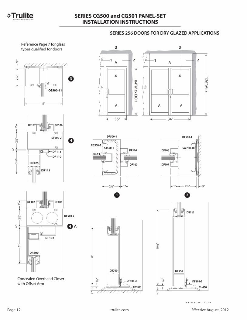
Page 12 trulite.com Eff ective August, 2012
1 2
3
4
4
SCALE 3” = 1’-0“
Concealed Overhead Closer with Offset Arm
1
3
1 22
4
3
4
SERIES 256 DOORS FOR DRY GLAZED APPLICATIONS
2½”
5”
CG500-11
¼”
DF500-2
2½”
1”3¼
”
DF111
DF110
DR225
DR111
1⁄8”
DF107 DF106
DF500-2
2½”
1”5”
DF102
DR400
1⁄8”
DF107 DF106
2½” 1”
DF107
DF106
CG500-5
RG-13
DF500-1
ST500-1
2½” ¼”1”
DF107
DF106
DF500-1
SW700-18
A
10½
”
3⁄16”
½”
DF108-2
DR111
DR950
TH450
8”
3⁄16”
½”
DF108-2
DR700
TH450
A A
A A A
36” 84”
84” Max D
OH
126” Max
Reference Page 7 for glass types qualified for doors

TM
SERIES CG500 and CG501
PANEL-SETINSTALLATION INSTRUCTIONS
Eff ective August, 2012 trulite.com Page 13
SCALE 3” = 1’-0“
4
Concealed Overhead Closer for Offset Arm
For SAC
SERIES 356 DOORS FOR WET GLAZED APPLICATIONS
1 33 4
55
6 6
2 2
5DF500-2
2½”
5”
5”
DF111
DF110
DR400
¼”
1⁄8”
68”
3⁄16”
½”
DF108-2
DR700
TH450
2
2½”4¾” ¼”
DF500-1
DR313
SW700-18
3⁄32”
4
DF108-2
DR315
DR103
DR104
DR314
4¾” 4¾”3⁄16”
3
1 1
2½” 4¾”
DF500-1
CG500-5
ST500-1
3⁄32”
DF500-2
2½”
5”
DF102
DR400
¼”
1⁄8” A
A
2½” 4¾”
DF500-1
DR313
DF111
DF110
CG500-5
ST500-1
3⁄32”2½” 4¾”
DF500-1
CG501-5
DR313
DF111
DF110
3⁄32”
B B B
42” Max 96” Max DOW
96” Max D
OH
Reference Page 7 for glass types qualified for doors

TM
SERIES CG500 and CG501
PANEL-SETINSTALLATION INSTRUCTIONS
Page 14 trulite.com Eff ective August, 2012
2½” ¼”1”
DF107
DF106
DF500-1
SW700-18
10½
”
3⁄16”
½”
DF108-2
DR105/RG-10
TH450
DR950
2½” 1”
DF107
DF106CG500-5
ST500-1
DF500-1
RG-13
DF500-2
2½”
1”5”
DF102
DR400
1⁄8”
DF107 DF106
ADA Bottom Rail
SCALE 3” = 1
4
Concealed Overhead Closer for Offset Arm
SERIES 356 DOORS FOR WET GLAZED APPLICATIONS
4
3
21
2½”
5”
CG500-11
¼”
DF500-2
2½”
1”5”
5”
DF111
DF110DR400
DR103
1⁄8”
DF107 DF106
1 1
3 3
4 4
2 2
A
For SAC
B B B
A A
Reference Page 7 for glass types qualified for doors

TM
SERIES CG500 and CG501
PANEL-SETINSTALLATION INSTRUCTIONS
Eff ective August, 2012 trulite.com Page 15
SCALE 3” = 1’-0“
5
Concealed Overhead Closer for Offset Arm
SERIES 356 DOORS FOR DRY GLAZED APPLICATIONS
1 33 4
55
6 6
2 2
6
5
23
1 1
4
A
DF500-2
2½”
5”
5”
DF111
DF110
DR400
¼”
1⁄8”
8”
3⁄16”
½”
DF108-2
DR700
TH450
2½”3⁄32”
4¾”
DF500-1
CG500-5
ST500-1 DR313
DF108-2
DR315
DR212
DR111
DR314
4¾” 4¾”3⁄16”
2½”4¾” ¼”
DF500-1
DF111
DF110
SW700-18
3⁄32”
2½”3⁄32”
4¾”
DF500-1
CG500-5
ST500-1 DR313
DR111
2½” 4¾”
DF500-1
CG501-5
ST500-1DR313
DF111
DF110
3⁄32”
A
DF500-2
2½”
5”
DF102
DR400
DR111
RG-15
1⁄8”
¼”
For SAC
A A A
Reference Page 7 for glass types qualified for doors

TM
SERIES CG500 and CG501
PANEL-SETINSTALLATION INSTRUCTIONS
Page 16 trulite.com Eff ective August, 2012
SCALE 3” = 1’-0“
4
4
Concealed Overhead Closer for Offset Arm
SERIES 356 DOORS FOR DRY GLAZED APPLICATIONS
3
21
1 1
3 3
4 4
2 2
DF500-2
2½”
1”5”
DF102
DR400
DR111
RG-15
1⁄8”
DF107 DF106
2½” ¼”1”
DF107
DF106
DF500-1
SW700-18
2½” 1”
DF107
DF106CG500-5
ST500-1
DF500-110
½”
3⁄16”
½”
DF108-2
DR111
DR950
TH450
DF500-2
2½”
1”5”
5”
DF111
DF110
DR400
1⁄8”
DF107 DF106
A
2½”
5”
CG500-11
¼”
For SAC
A A
AA A
Reference Page 7 for glass types qualified for doors

TM
SERIES CG500 and CG501
PANEL-SETINSTALLATION INSTRUCTIONS
Eff ective August, 2012 trulite.com Page 17
Series CG500/CG501
SHOWN SIMILAR
CG500 CG501
Dash No.
-1 -1
-2 -2
-3 -3
-4 -4
-5 -5
-6 -6
-11 -11
-12 CG500-12
-11
-6
-3
-3
-2
-2
-3
-6
-3
-3
-2
-12
-4 ST
50
0-4
Ste
el
-5
Inverted

TM
SERIES CG500 and CG501
PANEL-SETINSTALLATION INSTRUCTIONS
Page 18 trulite.com Eff ective August, 2012
RG-1 GASKETTYPICAL INTERIOR/EXTERIOREPDM
SC500 SETTING CHAIR
SB-11 SETTING BLOCK
RG-8 SPACER GASKETEPDM
*
*
*
*
FAS14-2 TYPICAL SPLINE SCREW
SV451-12
SILL SPLICEBRAKE METAL
ED500 END DAM
WD450 WATER DEFLECTOR
SB-12 SETTING BLOCKINVERTED HORIZONTAL
*
RW500 ANTI-WALK BLOCK
GT-1 TACKY TAPE
RG-13 GASKET(DRY GLAZING)EPDM
FAS25-1 Attach Steel
CG500
ACCESSORIES

TM
SERIES CG500 and CG501
PANEL-SETINSTALLATION INSTRUCTIONS
Eff ective August, 2012 trulite.com Page 19
*
RG-1 GASKETTYPICAL INTERIOR/EXTERIOREPDM
SC501 SETTING CHAIR
SB-13 SETTING BLOCK
RG-8 SPACER GASKETEPDM
*
*
*
FAS14-2 TYPICAL SPLINE SCREW
SV500-12
SILL SPLICEBRAKE METAL
ED500 END DAM
WD450 WATER DEFLECTOR
SB-14 SETTING BLOCKINVERTED HORIZONTAL
*
RW500 ANTI-WALK BLOCK
GT-1 TACKY TAPE
RG-13 GASKET(DRY GLAZING)EPDM
FAS25-1 Attach Steel
CG501
ACCESSORIES

TM
SERIES CG500 and CG501
PANEL-SETINSTALLATION INSTRUCTIONS
Page 20 trulite.com Eff ective August, 2012
OPTIONS AND LIMITATIONS
SERIES CG500 WET GLAZED APPLICATIONS
WITH 9⁄16” MONOLITHIC LAMINATED GLASS
Design
Pressure
P.S.F.
Glass Composition Manufacturer Glass Type
Intermediate
Vertical
Mullion
Wall
Jamb
Mullion
Maximum
Mullion
Length
Maximum D.L.O. Size Qualified
Glass
Types
Maximum
Spacing
C to CL L D.L.O. (W x H) Square Feet
+60/-60 CG500-7 & CG500-5Heavy Duty Mullion
9⁄16” glass consisting of two 1/4” H.S. glass lites and .090” Sentry Glas® interlayer.NOA# 07-1116.04
9⁄16” glass consisting of two 1/4” H.S. glass lites and .090” Butacite® PVB interlayer.NOA# 05-1208.02
CG500-4 & CG500-5
CG500-11 120” 48” 45½” x 96” 30.3
26.5
30.3
B
B
A
45½” x 84”
45½” x 96”
48”
48”
89”
126”
CG500-11
CG500-11
DuPont A
BDuPont
CG500-4 & CG500-5with ST500-4 Steel
+65/-65
+70/-80
Design
Pressure
P.S.F.
Intermediate
Vertical
Mullion
Wall
Jamb
Mullion
Maximum
Mullion
Length
Maximum D.L.O. Size Qualified
Glass
Types
Maximum
Spacing
C to CL L D.L.O. (W x H) Square Feet
30.3 A45½” x 96”48”126”CG500-11CG500-4 & CG500-5with ST500-4 Steel+70/-80
SERIES CG500 DRY GLAZED APPLICATIONS
WITH 9⁄16” MONOLITHIC LAMINATED GLASS
COMPARATIVE ANALYSIS OF GLASS BASED ON ASTM E-1300
DADE COUNTY BUILDING COMPLIANCE OFFICE ALLOWS COMPARATIVE ANALYSIS OF TESTED GLASS TYPES PROVIDED THE FIVE (5) FOLLOWING CONDITIONS ARE MET:
1. Does not exceed maximum cyclic pressure tested.
2. Does not exceed maximum span of mullion tested.
3. Does not exceed maximum mullion spacing of mullion tested.
4. Does not exceed maximum square footage of largest lite tested.
5. Does not exceed aspect ratio of 5:1 ( the ratio of the long side to the short side of a rectangle is defined as the aspect ratio.)

TM
SERIES CG500 and CG501
PANEL-SETINSTALLATION INSTRUCTIONS
Eff ective August, 2012 trulite.com Page 21
SCALE 3” = 1’-0“
6
1 2 3 4
6
7
5 5A
6A
7
5
6
5
2 3 41
CG500-3 CG500-2
2½”
¼”
CG500-3
RG-1
CG500-6
2½” SB-12
2½”
5”
CG500-11
¼”
CG500-5CG500-7
2½”
CG500-3 CG500-6
2½”
SB-11
2½”
5”
CG500-11
CG500-12
¼”
CG500-5
ST500-4
CG500-4
RG-1
2½”
CG500-5
CG500-12
CG500-4
RG-8
RG-1
2½”
CG500-3 CG500-2
CG500-12
2½”
3⁄8”
SB-11
SC500
A
A
INVERTED SILL
INVERTED HORIZONTAL
Reference Glass Options and Limitation Charts for Glass and Mullion Combinations
Interior
Silicone
9⁄16” Typ GlassBite
9⁄16”
Gla
ss B
iteTy
p.
TYPICAL DETAILS FOR WET GLAZED APPLICATIONS

TM
SERIES CG500 and CG501
PANEL-SETINSTALLATION INSTRUCTIONS
Page 22 trulite.com Eff ective August, 2012
SCALE 3” = 1’-0“
6
TYPICAL DETAILS FOR DRY GLAZED APPLICATIONS
1 4
6
7
5 5A
7
5
6
5
41
A
A
2½”
5”
CG500-11
CG500-12
¼”
CG500-3 CG500-6
2½”
2½”
5”
CG500-11 RG-13
¼”
CG500-3 CG500-6
2½”
CG500-3 CG500-2
2½”
¼”
CG500-3 CG500-2
CG500-12
2½”
3⁄8”
SB-11
SC500
CG500-5
ST500-4
CG500-4
RG-1
2½”
6A
INVERTED SILL
INVERTED HORIZONTAL
Interior

TM
SERIES CG500 and CG501
PANEL-SETINSTALLATION INSTRUCTIONS
Eff ective August, 2012 trulite.com Page 23
OPTIONS AND LIMITATIONS
SERIES CG501 WET GLAZE APPLICATIONS
FOR 15⁄16” INSULATED LAMINATED GLASS
Design
Pressure
P.S.F.
Glass Composition Manufacturer Glass Type
Intermediate
Vertical
Mullion
Wall
Jamb
Mullion
Maximum
Mullion
Length
Maximum D.L.O. Size Qualified
Glass
Types
Maximum
Spacing
C to CL L D.L.O. (W x H) Square Feet
+60/-60 CG501-7 & CG501-5Heavy Duty Mullion
15⁄16” Insulating glass consisting of two 1/4” H.S.glass lites with .090” Sentry Glas® interlayer with 1/2“ spacer and one 1/4” tempered outboard lite.NOA# 07-1116.04
15⁄16” Insulating glass consisting of two 1/4” H.S. glass lites with .090” Butacite® PVB interlayer with 1/2“ spacer and one 1/4” tempered outboard lite.NOA# 05-1208.02
CG501-4 & CG501-5
CG501-11 120” 48” 45½” x 96” 30.3
26.5
30.3
IB
IB
IA
45½” x 84”
45½” x 96”
48”
48”
89”
126”
CG501-11
CG501-11
DuPont IA
IBDuPont
CG501-4 & CG501-5with ST500-4 Steel
+65/-65
+70/-80
Design
Pressure
P.S.F.
Intermediate
Vertical
Mullion
Wall
Jamb
Mullion
Maximum
Mullion
Length
Maximum D.L.O. Size Qualified
Glass
Types
Maximum
Spacing
C to CL L D.L.O. (W x H) Square Feet
30.3 IA45½” x 96”48”126”CG501-11CG501-4 & CG501-5with ST500-4 Steel+70/-80
SERIES CG501 DRY GLAZE APPLICATIONS
FOR 15⁄16” INSULATED LAMINATED GLASS
COMPARATIVE ANALYSIS OF GLASS BASED ON ASTM E-1300
DADE COUNTY BUILDING COMPLIANCE OFFICE ALLOWS COMPARATIVE ANALYSIS OF TESTED GLASS TYPES PROVIDED THE FIVE (5) FOLLOWING CONDITIONS ARE MET:
1. Does not exceed maximum cyclic pressure tested.
2. Does not exceed maximum span of mullion tested.
3. Does not exceed maximum mullion spacing of mullion tested.
4. Does not exceed maximum square footage of largest lite tested.
5. Does not exceed aspect ratio of 5:1 (the ratio of the long side to the short side of a rectangle is defined as the aspect ratio.)

TM
SERIES CG500 and CG501
PANEL-SETINSTALLATION INSTRUCTIONS
Page 24 trulite.com Eff ective August, 2012
SCALE 3” = 1’-0“
6
TYPICAL DETAILS FOR WET GLAZED APPLICATIONS
7
5
6
5
2 3 41
CG501-3 CG501-2
2½”
¼”
CG501-3
RG-1
CG501-6
2½” SB-14
2½”
5”
CG501-11
¼”
CG501-3 CG501-6
2½”
CG501-5CG501-7
2½”2½”
5”
CG501-11
CG500-12
¼”
5"
CG501-5CG501-4
RG-8
RG-1
2½”
CG501-5CG501-4
2½”
ST500-4
CG501-3 CG501-2
CG500-12
2½”
3⁄8”
A
A
INVERTED SILL
INVERTED HORIZONTAL
1 2 3 4
6
7
5 5A
6A
Reference Glass Options and Limitation Charts for Glass and Mullion Combinations
9⁄16” Typ GlassBite
9⁄16”
Gla
ss B
ite
Silicone
Interior
Exterior

TM
SERIES CG500 and CG501
PANEL-SETINSTALLATION INSTRUCTIONS
Eff ective August, 2012 trulite.com Page 25
SCALE 3” = 1’-0“
6
TYPICAL DETAILS FOR DRY GLAZED APPLICATIONS
7
5
6
5
41
A
A
2½”
5”
CG501-11
¼”
CG501-3 CG501-6
2½”
CG501-3 CG501-2
CG500-12
2½”
3⁄8”
SB-13
SC501
CG501-5CG501-4
2½”
ST500-4
2½”
5”
CG501-11
CG500-12
¼”
5"
RG-13
CG501-3 CG501-2
2½”
¼”
CG501-3 CG501-6
2½” SB-14
INVERTED SILL
INVERTED HORIZONTAL
1 4
6
7
5 5A
6A
Interior
Exterior

TM
SERIES CG500 and CG501
PANEL-SETINSTALLATION INSTRUCTIONS
Page 26 trulite.com Eff ective August, 2012
Measure width of masonry opening at the top, middle and bottom as shown in FIG. 1.*Sill Flashing Length = Smallest dimension minus (-) 1/2”.
NOTE: 1/4“ caulk joint is minimum that should be used. (3/8” to 1/2“ is acceptable).
Measure height of masonry opening in several places. See FIG. 2*Frame Height = Smallest dimension minus (-) 5/8”.1/4” shim/caulk at head1/8” for CG450-12 sill flashing1/4” shim/caulk below sill flashing
NOTE: 1/4“ caulk joint is minimum that should be used. (3/8” to 1/2“ is acceptable.
MEASURE
MEASURE
MEASURE
¼”¼”
MEA
SURE
MEA
SURE
MEA
SURE
¼”
3⁄8”
FRAME HEIGHT:
FIG. 1
FIG. 2
*MASONRY OPENING
*SILL FLASHING LENGTH
*F
RA
ME
HE
IGH
T
*M
AS
ON
RY
OP
EN
ING
3⁄8”3⁄8” *NET FRAME WIDTH
FRAME FABRICATION
STEP 1.
DETERMINE NET FRAME WIDTH AND HEIGHT BY MEASURING MASONRY OPENING:
FRAME WIDTH:
Measure width of masonry opening at the top, middle and bottom as shown in FIG. 1. *Sill Flashing Length = Smallest dimension minus (-) 1/2"
Note: 1/4" caulk joint is minimum that should be used. 3/8" to 1/2" is acceptable.
FRAME HEIGHT:
Measure height of masonry opening in several places. See FIG. 2. *Frame Height = Smallest dimension minus (-) 5/8". 1/4” shim/caulk at head 1/8 for sill fl ashing 1/4” shim/caulk below sill fl ashing
Note: 1/4" caulk joint is minimum that should be used. 3/8" to 1/2" is acceptable.

TM
SERIES CG500 and CG501
PANEL-SETINSTALLATION INSTRUCTIONS
FRAME FABRICATION
STEP 2.
Use DJ500/501 drill jig or CG500/501 Punch Die Set forfabricating spline hole locations in verticals. Fabricate holes asshown in FIGS. 4 & 5.
Eff ective August, 2012 trulite.com Page 27
13
2
1
1/4
2
verticalmullion
filler
CG500-11
CG500-6
HEADER
HORIZONTAL
CG500-2SILL
2
DRILL JIG
INTERIOR GLAZINGEXTERIOR GLAZING
FIG. 3 FIG. 4
CG500-2HEADER
CG450-1SILL
BOTTOM OF VERTICAL
TOP OF HORIZONTAL
TOP OF VERTICAL
BOTTOM OF VERTICAL
TOP OF HORIZONTAL
TOP OF VERTICAL
USE LETTER "F" (.257Ø) DRILL
JAMB
1/4
1/4
2
1/4
CG500-6HORIZONTAL
2
1/4
2
1/4
DJ501
DJ501
DJ501
DJ501
DJ501
DJ501
Exterior Exterior
Series CG500S2 Series CG501S2
Shown CG500 Similar CG501
-2 -2
-4 -4
-5 -5
-6 -6
-7 -7
-11 -11
SPLINE FABRICATION
PART NO. CHART-5 -11
-4-7
NOTE: RG-1
Gasket reglet is always to exterior.
EXTERIOR
CG500 Pocket
CG501 PocketFILLER
VERTICAL MULLION
TM
SERIES CG500 and CG501
PANEL-SETINSTALLATION INSTRUCTIONS
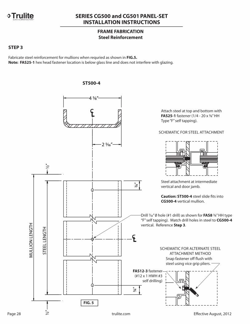
FRAME FABRICATION
Steel Reinforcement
Page 28 trulite.com Eff ective August, 2012
STEP 3
Fabricate steel reinforcement for mullions when requried as shown in FIG.5.
Note: FAS25-1 hex head fastener location is below glass line and does not interfere with glazing.
ST500-4
STEE
L LE
NG
TH
CL
CL
MU
LLIO
N L
ENG
TH
½
”½
”
¾”
¾”
4 5⁄8”
2 5⁄16”
ST500-4
SCHEMATIC FOR STEEL ATTACHMENT
Attach steel at top and bottom with FAS25-1 fastener (1/4 - 20 x 3⁄8” HH Type “F” self tapping).
Steel attachment at intermediate vertical and door jamb.
Caution: ST500-4 steel slide fi ts into CG500-4 vertical mullion.
Drill 7⁄32” 0 hole (#1 drill) as shown for FAS8 3⁄8” HH type “F” self tapping). Match drill holes in steel to CG500-4 vertical. Reference Step 3.
SCHEMATIC FOR ALTERNATE STEEL ATTACHMENT METHOD
Snap fastener off fl ush with steel using vice grip pliers.
FAS12-3 fastener(#12 x 1 HWH #3
self drilling)
FIG. 5
TM
SERIES CG500 and CG501
PANEL-SETINSTALLATION INSTRUCTIONS
Eff ective August, 2012 trulite.com Page 29
FRAME FABRICATION
Head/Sill
STEP 4
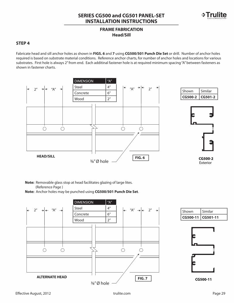
Fabricate head and sill anchor holes as shown in FIGS. 6 and 7 using CG500/501 Punch Die Set or drill. Number of anchor holes required is based on substrate material conditions. Reference anchor charts, for number of anchor holes and locations for various substrates. First hole is always 2” from end. Each additinal fastener hole is at required minimum spacing “A” between fasteners as shown in fastener charts.
CG500-2Exterior
CG500-11
2” 2”
2”2” “A” “A”
“A”“A”
Note: Removable glass stop at head facilitates glazing of large lites. (Reference Page )Note: Anchor holes may be punched using CG500/501 Punch Die Set.
DIMENSION “A”
Steel 4”
Concrete 6”
Wood 2”
Shown Similar
CG500-2 CG501-2
Shown Similar
CG500-11 CG501-11
3⁄8” Ø hole
3⁄8” Ø hole
DIMENSION “A”
Steel 4”
Concrete 6”
Wood 2”
FIG. 6
FIG. 7
HEAD/SILL
ALTERNATE HEAD

TM
SERIES CG500 and CG501
PANEL-SETINSTALLATION INSTRUCTIONS
FRAME FABRICATIONS
Wall Jamb
Fabricate wall jamb for anchor holes, when required as shown in FIG. 8. Number of anchors required is dependent on mullion length and substrate material. Reference Anchor Charts (Pages 45-50).
STEP 5
Page 30 trulite.com Eff ective August, 2012
CG500-11
Shown Similar
CG500-11 CG501-11
When charted anchor holes are shown at same location as intermediate horizontal, then drill holes directly above or below horizontal to avoid fastener installation interference.
Note: Locate anchors as close to charted dimensions as possible.
3⁄8” Ø hole
Note: Anchor holes may be punched using CG500/501
Punch Die Set
Wall Jamb
FIG. 8

TM
SERIES CG500 and CG501
PANEL-SETINSTALLATION INSTRUCTIONS
Typ. Each End
Eff ective August, 2012 trulite.com Page 31
FRAME FABRICATION
Subsill Flashing
Fabricate CG500-12 for non-structural fastener holes as shown in FIG. 9
STEP 6
CG500-12
MID-POINT
24"
“V” Groove
Holes for Non-Structural Fasteners
Drill 3⁄16” Ø hole and csk for non-structural fastener
See Page 35 for subsill abutting door jamb.
Drill 3⁄16” Ø hole and csk for non-structural fasteners to temporarily attach subsill to substrate as shown. Repeat this hole pattern for each additional 12’-0” length or as required until structural fasteners are installed.
FIG. 9

TM
SERIES CG500 and CG501
PANEL-SETINSTALLATION INSTRUCTIONS
FRAME ASSEMBLY
Joinery Tape Application
STEP 1
FIG. 10
Page 32 trulite.com Eff ective August, 2012
GLAZING TAPE INSTALLATION PROCEDURES: (Ref. FIG. 10 below)Ref. Step 2 FIG. 11 for locations.
A. Cut GT-1 1⁄8” x ½ ” Tacky Tape approximately 2¾ ” long.B. Clean surfaces where tape is to be applied with isopropyl alcohol or solvent to remove all dirt and cutting oils. Allow surface to dry before applying tape.C. Position tape on vertical mullions at horizontal joint intersections, as shown on Page 33.D. Just prior to frame assembly, remove portective cover and screw joints together.E. Use a box knife to trim excess sealant tape where exposed. Do not pull tape to trim.
Shown Similar
CG500-4
CG500-5
CG501-4
CG501-5
Critical Seal Area
RG-8 spacer gasket runs full length on verticals.
RG-1 gasket reglet is always to exterior.
GT-1 TACKY TAPE
2¾ ”approx.
2¾ ”
Interior Side

TM
SERIES CG500 and CG501
PANEL-SETINSTALLATION INSTRUCTIONS
Eff ective August, 2012 trulite.com Page 33
CAPTURED FRAME ASSEMBLY
Vertical to Horizontal Joinery
STEP 2
Install RG-8 interior spacer gaskets into vertical and horizontal members prior to frame assembly. Cut spacer gaskets to D.L.O. dimensions.
Deep Pocket
Inverted Horizontal
Shallow Pocket
Note: Shallow glazing pockets cannot face each other.
Glass Stop
Glass Stop
Glass Stop
Head
Sill
RG-8
FAS14-2 Spline Screw
Anchor Hole(s)Ref. Page 29 FIG. 6
RG-8
Spacer Gasket
CG500-11
Optional Head
OPTIONAL HEAD
REQUIRES HORIZONTAL
ORIENTATED AS SHOWN
BELOW.
CG500-11
HorizontalRef. Page
FIG. 11
TM
SERIES CG500 and CG501
PANEL-SETINSTALLATION INSTRUCTIONS
FRAME INSTALLATION
Sill Flashing Installation and Sealant Application
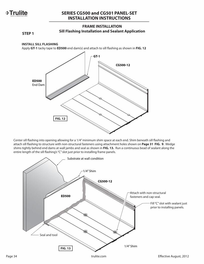
INSTALL SILL FLASHING
Apply GT-1 tacky tape to ED500 end dam(s) and attach to sill fl ashing as shown in FIG. 12
STEP 1
Page 34 trulite.com Eff ective August, 2012
Center sill flashing into opening allowing for a 1/4” minimum shim space at each end. Shim beneath sill flashing and attach sill flashing to structure with non-structural fasteners using attachment holes shown on Page 31 FIG. 9. Wedge shims tightly behind end dams at wall jambs and seal as shown in FIG. 13. Run a continuous bead of sealant along the entire length of the sill flashing’s “C” slot just prior to installing frame panels.
GT-1
ED500
End Dam
CG500-12
CG500-12
ED500
1/4” Shim
Substrate at wall condition
Seal and tool
Fill “C” slot with sealant just prior to installing panels.
Attach with non-structuralfasteners and cap seal.
FIG. 12
FIG. 13
1/4” Shim

TM
SERIES CG500 and CG501
PANEL-SETINSTALLATION INSTRUCTIONS
Splices should be located every 12 to 15 feet with a 1/2” expansion joint as shown in FIG. 15.
TH450 Threshold is anchoredto finished floor. Reference doorand doorframe instructions.
Doorjamb at side light
Thoroughly seal tosubstrate and flashing
CG500-12
Sill Flashing
Shim
½” Minimum
Embed SV500 Splice Sleeve in sealant
Seal entire length of splice sleeve
Apply bond breaker tape to one side of sleeve toavoid 3 side adhesion.
SILL FLASHING SPLICE
SILL FLASHING AT DOORJAMB
FIG. 15
FIG. 14
Doorjamb rests on finished floor
CG500-12
Note: ST501 steel slide fits into DF500-1 and must be installed prior to installing door frame.
Reference Anchor ChartsPages 45-50
Eff ective August, 2012 trulite.com Page 35
FRAME INSTALLATION
STEP 2

TM
SERIES CG500 and CG501
PANEL-SETINSTALLATION INSTRUCTIONS
Page 36 trulite.com Eff ective August, 2012
FRAME INSTALLATION
Panel-Set Assembly
STEP 3
Install assembled frame panels into opening starting with jam and continue working toward the last bay. Reference illustrations shown below. Use option “A” or “B” as required. CAUTION: ST500-4 steel slide fi ts into mullion and must be inserted and attached prior to installing panels.
Wall Jamb
Wall Jamb Last Bay Wall Jamb
Option A
Option B
Note: Make sure sill is positioned fl ush at bottom as shown.
RG-8 Spacer GasketInstalled on interior side for WET GLAZED assembly .
RG-13 Gasket Installed on interior side for DRY GLAZED assembly.
FIG. 16
FIG. 17

TM
SERIES CG500 and CG501
PANEL-SETINSTALLATION INSTRUCTIONS
RG-13
RG-8
Eff ective August, 2012 trulite.com Page 37
FRAME INSTALLATION
Panel-Set Frame Attachment to Substrate
STEP 4
Shim beneath subsill as required at fasteners. Match drill holes through sill into sub-strate for perimeter fasteners. Match drill holes in head and wall jamb into substrate. Shim and anchor panels to substrate.
STEP 5
Completely seal exterior and interior perimeter with a continuous bead of DOW 795
sealant.
Note: RG-8 is shown for wet glazing. Replace with RG-13 for dry glazing.
HEAD ALTERNATE HEAD
SILL WALL JAMB
Structural fastener
Structural fastener
Apply DOW 995
sealant into anchor hole
RG-8 or RG-13
Sealant not required
Sealant not required
RG-8 Spacer GasketWET GLAZED
RG-13 Gasket DRY GLAZED
For D.L.O. heights 72” or greater, attach fi ller to mullion at midpoint and 18” above and below midpoint with #12 x 1½ ” #3 FHP self drill and snap off excess using pliers.
FIG. 18 FIG. 19
FIG. 20
FIG. 21
FIG. 22
Reference Anchor Charts Pages 45-50

TM
SERIES CG500 and CG501
PANEL-SETINSTALLATION INSTRUCTIONS
Page 38 trulite.com Eff ective August, 2012
GLAZING
Setting Block Installation
1/4 1/41/2
6" minimum
Edge of glass
4” long setting blockminimum
Setting block (2) per lite
Start head and jamb gaskets at center and corners
Start sill gaskets at setting blocks
GLASS SIZE = DAYLIGHT OPENING (D.L.O.) + 5/8”
D.L.O.
D.L
.O.
FIG. 23
FIG. 24
FIG. 25
STEP 1.
REMOVE ALL TRASH FROM GLAZING POCKETS AND REGLETS.Set glass on two (2) identical setting blocks positioned at 1/4 points in opening. Reference Dead Load Charts for locations on intermediate horizontal. Setting blocks are not to be placed closer than 6” from the edge of glass.
GLASS SIZE = DAYLIGHT OPENING (D.L.O.) + 11⁄8”
Reference Dead Load Charts for intermediate horizontal
Four exterior gaskets are cut 3/16” longer per foot than D.L.O. (width and height; Ref. FIG. 24) to allow for shrinkage.It is important that gaskets are cut and installed as shown in FIG. 25.
EXTERIOR GASKET INSTALLATION

TM
SERIES CG500 and CG501
PANEL-SETINSTALLATION INSTRUCTIONS
Eff ective August, 2012 trulite.com Page 39
GLAZING
Embed WD450 in sealantsealant as shown
Note:Vertical
omitted forclarity
WD450
A. Make sure interior glasket is installed.B. Prepare frame openings for glass as instructed on Page and install setting chairs in sill.C. Glaze from bottom to top following the four step procedure shown.D. Center glass into opening making sure proper glass penetration is achieved. Rest glass on setting blocks and press tightly against interior gasket.E. Apply DOW 995 sealant to one end of water diverter and position at each end of horizontal, as shown, after glazing lower lites.
NOTE: Reference CG500 or CG501 Accessories to properly select setting chairs,
setting blocks and water diverters.
Setting Block
Setting Block(Required with inverted horizontal)
WD450 Install after glazing lower lites
CG500-12
NOTE: May be inverted to facilitate glazing large lites.
12
3
RG-13 Gasket
RG-8 Spacer Gasket
4
FIG. 26
FIG. 27
FIG. 28
FIG. 29
WD450 Shown. WD451 for
Series CG501 Similar.

TM
SERIES CG500 and CG501
PANEL-SETINSTALLATION INSTRUCTIONS
Page 40 trulite.com Eff ective August, 2012
GLAZING
Glass Bite9⁄16"
F. Continue glazing following the four step procedure.G. Install hook-in glass stops as shownH. Prepare top load gaskets and install as shown on Page 38 .I. Mask off glass and aluminum with 2” wide low adhesion masking tape. Fill cavity with Dow
995 sealant as shown, FIG. 31 and tool. Remove masking tape immediatley after installation of sealant and tooling. Take care not to damage or pull sealant from cavity when removing masking tape. NOTE: Skip item I. above if dry glazing.
SCHEMATIC OF GLAZING SEQUENCE
Exterior
Low adhesionmasking tape
DOW 995Silicone sealant
Non-Structural Fastener Structural Fastener
(Ref. Anchor Charts, Pages 45-50)
RG-13 Gasket for dry glazed
RG-8 Spacer Gasketfor wet glazed
RG-1
FIG. 29 FIG. 30
FIG. 31
Exterior Gasket Interior Gasket Interior Gasket
TM
SERIES CG500 and CG501
PANEL-SETINSTALLATION INSTRUCTIONS
Eff ective August, 2012 trulite.com Page 41
GLAZING GASKETS FOR STOREFRONT SYSTEMS
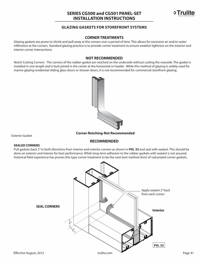
CORNER TREATMENTSGlazing gaskets are prone to shrink and pull away at the corners over a period of time. This allows for excessive air and/or water infi ltration at the corners. Standard glazing practice is to provide corner treatment to ensure weather tightness on the exterior and interior corner intersections.
NOT RECOMMENDEDNotch Cutting Corners - The corners of the rubber gasket are notched on the underside without cutting the nearside. The gasket is installed in one length and is butt joined in the center at the horizontal or header. While this method of glazing is widely used for marine glazing residential sliding glass doors or shower doors, it is not recommended for commercial storefront glazing.
RECOMMENDEDSEALED CORNERS
Pull gaskets back 2” in both directions from interior and exterior corners as shown in FIG. 32 and seal with sealant. This should be done on exterior and interior for best performance. While long-term adhesion to the rubber gaskets with sealant is not assured, historical fi eld experience has proven this type corner treatment to be the next best method short of vulcanized corner gaskets.
Corner Notching-Not Recommended
Apply sealant 2” back from each corner
FIG. 32
SEAL CORNERSInterior
2”
2”
Exterior Gasket
TM
SERIES CG500 and CG501
PANEL-SETINSTALLATION INSTRUCTIONS
Page 42 trulite.com Eff ective August, 2012
GLAZING
Glass Size Formulas
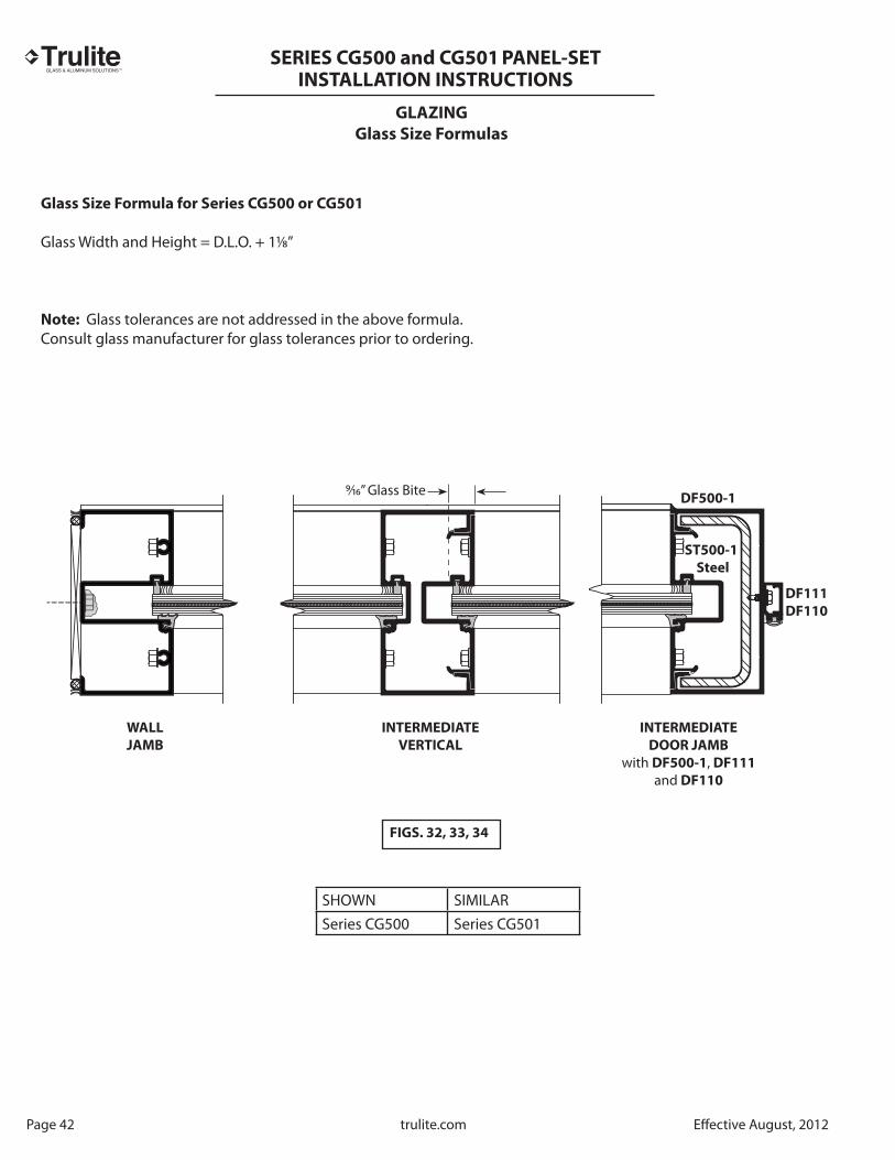
Glass Size Formula for Series CG500 or CG501
Glass Width and Height = D.L.O. + 11⁄8”
Note: Glass tolerances are not addressed in the above formula.Consult glass manufacturer for glass tolerances prior to ordering.
9⁄16” Glass Bite
ST500-1
Steel
DF500-1
DF111
DF110
INTERMEDIATE
DOOR JAMB
with DF500-1, DF111
and DF110
INTERMEDIATE
VERTICAL
WALL
JAMB
SHOWN SIMILARSeries CG500 Series CG501
FIGS. 32, 33, 34

TM
SERIES CG500 and CG501
PANEL-SETINSTALLATION INSTRUCTIONS
Eff ective August, 2012 trulite.com Page 43
GLAZING
Transom Glass Size Formula
Frame for Off set Hung Door for Surface Closer
See Glazing for Glass Installation
9⁄16”
Gla
ss B
ite
D.O.W.
D.L.O.1” 1”
TRANSOM BAR
OFFSET HUNG DOOR
FOR SURFACE CLOSER
WET GLAZE SHOWN
INTERMEDIATE JAMB
WITH ST500-1 STEEL
JAMB AT
WALL
3⁄8” Ø anchor typical
FAS8 (1/4 - 20 x 3⁄8” HH Type “F” self tapping) for attaching ST500-1 optional steel when required. Locate 1 each at top and bottom.
D.L
.O.
2½ ”
DR104DR103
DF111
DF110
with RG-5 weatheringDR400
DF500-2
DF106
SB-15
DF107
Glass Height = D.L.O. + 1⁄8”
DF500-1DF500-1
SW700-18
Filler
DF107
DF106
GlassWidth = Door Opening minus (-7⁄8”)

TM
SERIES CG500 and CG501
PANEL-SETINSTALLATION INSTRUCTIONS
Page 44 trulite.com Eff ective August, 2012
GLAZING
Transom Glass Size Formula
Frame for Off set Hung Door for Surface Closer
See Glazing for Glass Installation
D.L.O.1” 1”
D.O.W.
TRANSOM BAR
OFFSET HUNG DOOR
FOR C.O.C WITH
OFFSET ARM
DRY GLAZE SHOWN
INTERMEDIATE JAMB
WITH ST500-1 STEEL AT TRANSOM
TRANSOM
JAMB AT
WALL
3⁄8” Ø anchor typical
FAS25-1 (1/4 - 20 x 3⁄8” HH Type “F” self tapping) for attaching ST500-1 optional steel when required. Locate 1 each at top and bottom.
D.L
.O.
2½ ”
DR111DR111
DR400
DF500-2
DF106
Glass Height = D.L.O. +1 1⁄8”
DF500-1DF500-1
SW700-18
Filler
DF107
DF106
Glass Width = Door Opening minus (-7⁄8”)
1”
SB-15
DF102
9⁄16”
Gla
ssBi
te
Dry Glazing Shown(Wet Glazing Similar)
Dry Glazed Door Shown(Wet Glazed Similar)
DF107

TM
SERIES CG500 and CG501
PANEL-SETINSTALLATION INSTRUCTIONS
PE
RIM
ET
ER
FA
ST
EN
ER
LO
CA
TIO
NS
Ty
pic
al
Att
ac
hm
en
t to
Wo
od
/Ste
el/
Co
nc
rete
Su
bst
rate
CG
50
0
CG
50
1
RE
SIS
TO
R
ST
OR
EF
RO
NT
SY
ST
EM
S
Eff ective August, 2012 trulite.com Page 45

TM
SERIES CG500 and CG501
PANEL-SETINSTALLATION INSTRUCTIONS
Page 46 trulite.com Eff ective August, 2012
PE
RIM
ET
ER
FA
ST
EN
ER
LO
CA
TIO
NS
Ty
pic
al
Att
ac
hm
en
t to
Wo
od
/Ste
el/
Co
nc
rete
Su
bst
rate
CG
50
0
CG
50
1
RE
SIS
TO
R
ST
OR
EF
RO
NT
SY
ST
EM
S

TM
SERIES CG500 and CG501
PANEL-SETINSTALLATION INSTRUCTIONS
PE
RIM
ET
ER
FA
ST
EN
ER
LO
CA
TIO
NS
Ty
pic
al
Att
ac
hm
en
t to
Wo
od
/Ste
el/
Co
nc
rete
Su
bst
rate
Eff ective August, 2012 trulite.com Page 47
CG
50
0
CG
50
1
RE
SIS
TO
R
ST
OR
EF
RO
NT
SY
ST
EM
S
TM
SERIES CG500 and CG501
PANEL-SETINSTALLATION INSTRUCTIONS
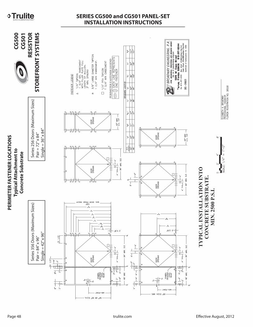
Page 48 trulite.com Eff ective August, 2012
PE
RIM
ET
ER
FA
ST
EN
ER
LO
CA
TIO
NS
Ty
pic
al
Att
ac
hm
en
t to
Co
nc
rete
Su
bst
rate
Serie
s 35
6 D
oors
(Max
imum
Siz
es)
Pair
= 84
” x 9
6”Si
ngle
= 4
2” x
96”
Serie
s 25
6 D
oors
(Max
imum
Siz
es)
Pair
= 72
” x 8
4”Si
ngle
= 3
6” x
84”
CG
50
0
CG
50
1
RE
SIS
TO
R
ST
OR
EF
RO
NT
SY
ST
EM
S

TM
SERIES CG500 and CG501
PANEL-SETINSTALLATION INSTRUCTIONS
PE
RIM
ET
ER
FA
ST
EN
ER
LO
CA
TIO
NS
Ty
pic
al
Att
ac
hm
en
t to
Ste
el
Su
bst
rate
Eff ective August, 2012 trulite.com Page 49
Serie
s 35
6 D
oors
(Max
imum
Siz
es)
Pair
= 84
” x 9
6”Si
ngle
= 4
2” x
96”
Serie
s 25
6 D
oors
(Max
imum
Siz
es)
Pair
= 72
” x 8
4”Si
ngle
= 3
6” x
84”
CG
50
0
CG
50
1
RE
SIS
TO
R
ST
OR
EF
RO
NT
SY
ST
EM
S

TM
SERIES CG500 and CG501
PANEL-SETINSTALLATION INSTRUCTIONS
Page 50 trulite.com Eff ective August, 2012
PE
RIM
ET
ER
FA
ST
EN
ER
LO
CA
TIO
NS
Ty
pic
al
Att
ac
hm
en
t to
Wo
od
Su
bst
rate
Serie
s 35
6 D
oors
(Max
imum
Siz
es)
Pair
= 84
” x 9
6”Si
ngle
= 4
2” x
96”
Serie
s 25
6 D
oors
(Max
imum
Siz
es)
Pair
= 72
” x 8
4”Si
ngle
= 3
6” x
84”
CG
50
0
CG
50
1
RE
SIS
TO
R
ST
OR
EF
RO
NT
SY
ST
EM
S

TM
SERIES CG500 and CG501
PANEL-SETINSTALLATION INSTRUCTIONS