TM Imaging Spectrograph - Massachusetts Institute of ...rowan/page4/page6/assets/HoloSpec_V... ·...
44
December 2002 HoloSpec Imaging Spectrograph OPERATIONS MANUAL 2004945 V2.0 Kaiser Optical Systems, Inc. 371 Parkland Plaza Ann Arbor, MI 48103 TM
-
Upload
nguyendieu -
Category
Documents
-
view
213 -
download
1
Transcript of TM Imaging Spectrograph - Massachusetts Institute of ...rowan/page4/page6/assets/HoloSpec_V... ·...

December 2002
HoloSpec Imaging
Spectrograph
OPERATIONS MANUAL 2004945 V2.0
Kaiser Optical Systems, Inc. 371 Parkland Plaza
Ann Arbor, MI 48103
TM


HoloSpec Imaging Spectrograph iii
2004945 V2.0
This manual is intended for use by customers of Kaiser Optical Systems, Inc. No part of this manual may be reproduced or transmitted in any form or by any means, electronic or mechanical, including photocopying, recording, or information storage and retrieval systems, for any purpose other than the purchaser's personal use, without the express written permission of Kaiser Optical Systems, Inc. Under the law, copying includes translation into another language.
Information contained herein is deemed to be accurate at the time of writing. Kaiser Optical Systems, Inc., reserves the right to change the information and specification contained within without notice.
Kaiser Optical Systems, Inc. will provide telephone consultation for this product during normal U.S. East Coast business hours, 8:00 A.M. to 5:00 P.M. Under no circumstances does telephone consultation affect the terms of any warranty agreement.
Kaiser Optical Systems, Inc. 371 Parkland Plaza Ann Arbor, MI 48103 Phone: (734) 665-8083 Fax: (734) 665-8199 E-mail: [email protected] Website: www.kosi.com CAUTION. Performing procedures, using controls, or adjusting the spectrograph other than as specified in the manual may result in hazardous radiation exposure.
Holographic SuperNotch is a registered trademark, and Holographic SuperNotch-Plus, HoloPlex, HoloSpec, Volume Phase Holographics, and VPH are trademarks of Kaiser Optical Systems, Inc.
2002 Kaiser Optical Systems, Inc. All rights reserved. Printed in the United States of America.

iv HoloSpec Imaging Spectrograph
2004945 V2.0
Table of Contents
LIST OF FIGURES AND TABLES ________________________________________v
IMPORTANT SYMBOLS USED IN THIS MANUAL ______________________ vii
PREFACE ___________________________________________________________ viii
U.S. EXPORT COMPLIANCE__________________________________________ viii
1 INTRODUCTION____________________________________________________1 1.1 The VPH System™ _____________________________________________ 1
2 SPECIFICATIONS AND OPTICAL PERFORMANCE ____________________3 2.1 Specifications __________________________________________________ 3 2.2 Curvature in Image of Slit _______________________________________ 7
3 UNPACKING AND HANDLING _______________________________________8
4 INSTALLATION AND OPERATION___________________________________9 4.1 Installation and Operation Procedure ______________________________ 9 4.2 Spectrograph Cover_____________________________________________ 9 4.3 Internal Slit (HoloSpec f/1.8i only) ________________________________ 11 4.4 Installing and Removing the VPH Grating _________________________ 12 4.5 Notch Filter (HoloSpec f/1.8i only) ________________________________ 13 4.6 Input Adapter_________________________________________________ 15 4.7 Aligning the Pre-Filter with Fiber and External Slit Input Adapters
(HoloSpec f/1.8i only)___________________________________________ 17 4.8 Aligning the Pre-Filter with the Aperture Input Adapter (HoloSpec
f/1.8i only) ____________________________________________________ 18 4.9 Camera ______________________________________________________ 18 4.10 External Slit Input Adapter _____________________________________ 19
5 WARRANTY INFORMATION _______________________________________22
APPENDIX A. OPTIONS_______________________________________________23
APPENDIX B. CLEANING HOLOGRAPHIC FILTERS AND GRATINGS ____29
APPENDIX C. SLIT CURVATURE ______________________________________30
APPENDIX D. LIST OF APPROVED DISTRIBUTORS_____________________32
APPENDIX E. LIST OF KAISER OPTICAL SYSTEMS OFFICES ___________33

HoloSpec Imaging Spectrograph v
2004945 V2.0
List of Figures and Tables
Figure 2.1. Interior of the HoloSpec f/1.8i, showing the VPH grating and mount and the internal slit holder assembly ____________________________________3
Figure 2.2. Interior of the HoloSpec f/1.8i, showing the input adapter support plate, base plate, notch filter and mount, base plate channel, horizontal tilt adjustment, vertical tilt adjustment, and camera mounting support plate _____4
Figure 2.3. Interior of the HoloSpecs f/1.4–2.2, showing the camera focus thumbwheel, latch pocket, VPH grating and mount, base plate, and base plate channel________________________________________________________4
Figure 2.4. Interior of the HoloSpecs f/1.4–2.2, showing the latch pocket, input adapter support plate, camera mounting support plate, horizontal tilt adjustment screw, and vertical tilt adjustment screw ______________________5
Table 2.1. Aperture Ratio Based on 25-mm Image Plane Width _______________ 6
Figure 2.5. Horizontal displacement of rays with respect to vertical position along the slit for grating HSG-532-LF ___________________________________7
Figure 4.1. The cover slides easily over the HoloSpec frame ___________________10
Figure 4.2. Installing the slit _____________________________________________11
Figure 4.3. Removing the slit ____________________________________________12
Figure 4.4. Installing a VPH grating ______________________________________14
Figure 4.5. Removing the notch filter______________________________________15
Figure 4.6. Available input adapters ______________________________________16
Figure 4.7. Installing the input adapter ____________________________________16
Figure 4.8. The camera mount ___________________________________________20
Figure 4.9. Locations of the image adjust thumbwheel and the slit focus thumbwheel________________________________________________________17
Figure 4.10. Removing a slit from an input adapter__________________________21
Table A.1. Raman Gratings: Model Number, Spectral Coverage, Average Reciprocal Linear Dispersion, and Part Number ________________________ 23
Table A.2. Fluorescence and Visible Gratings: Spectral Coverage and Linear Dispersion ________________________________________________________ 24
Table A.3. Holographic Notch Filters ____________________________________ 25

vi HoloSpec Imaging Spectrograph
2004945 V2.0
Table A.4. Optical Specifications of SuperNotch-Plus Filters________________ 25
Table A.5. Slits _______________________________________________________ 26
Table A.6. Shutters ___________________________________________________ 27
Table A.7. Linear Fiber Array Adapters__________________________________ 27
Table A.8. SMA Adapter_______________________________________________ 28
Table A.9. Adapter Kits for Mounting CCD Cameras to HoloSpec Spectro-graphs ___________________________________________________________ 28

HoloSpec Imaging Spectrograph vii
2004945 V2.0
Important Symbols Used in This Manual
THIS SYMBOL IS USED TO IDENTIFY IMPORTANT OPERATING INSTRUCTIONS.
THIS SYMBOL IS USED TO ALERT THE USER TO THE DANGER OF EXPOSURE TO HAZARDOUS VISIBLE LASER RADIATION.

viii HoloSpec Imaging Spectrograph
2004945 V2.0
Preface
This manual contains information for users concerning the HoloSpec spectrographs.
Caution: Read this manual carefully before using a HoloSpec spectrograph for the first time.
Warning: Performing procedures, using controls, or adjusting the spectrograph other than as specified in the manual may result in hazardous radiation exposure.
U.S. Export Compliance Strict compliance with U.S. export control laws is the policy of Kaiser Optical Systems, Inc.
Export and re-export of spectrographs manufactured by Kaiser Optical Systems, Inc., are subject to U.S. Export Administration Regulations. These regulations are administered by the Commerce Department. Shipments of certain components are regulated by the State Department under the International Traffic in Arms Regulations.
Applicable restrictions vary based on the product involved and its country of destination. When there is uncertainty about the obligations imposed by U.S. law, clarification should be obtained from Kaiser Optical Systems, Inc., or an appropriate U.S. Government agency.

HoloSpec Imaging Spectrograph ix
2004945 V2.0
This page intentionally left blank

x HoloSpec Imaging Spectrograph
2004945 V2.0
This page intentionally left blank

HoloSpec Imaging Spectrograph 1
2004945 V2.0
1 Introduction The HoloSpec™ line of holographic imaging spectrographs from Kaiser Optical Systems, Inc., (KOSI) features significant advances in high-performance spectroscopy. The HoloSpec spectrographs use Volume Phase Holographics™ (VPH™) in an axial transmissive spectrograph configuration to provide superior imaging, excellent spectral resolution, high efficiency, low scatter, and unsurpassed throughput.1 All of these features are offered in a system that is compact and extremely simple to set up, operate, and maintain.
The HoloSpec is available in two versions. The HoloSpec f/1.8i incorporates optics for pre-filtering the light before it enters the heart of the spectrograph. A holographic SuperNotch-Plus™ filter is included with the HoloSpec f/1.8i for filtering out light at the laser wavelength. The HoloSpec f/1.4, HoloSpec f/1.8, and HoloSpec f/2.2 are offered without the prefiltering optics and are ideal for applications in which pre-filtering is either performed remotely or not required. Throughout the rest of this manual, the HoloSpec spectrographs without a prefiltering section will be referred to collectively as the HoloSpecs f/1.4–2.2.
1.1 The VPH System KOSI first introduced Volume Phase Holographics technology in its line of holographic notch filters for spectroscopic spectrographs. These notch filters serve as laser-blocking filters in Raman and fluorescence spectroscopy. The same technology used to produce holographic notch filters has been applied to the production of high-quality transmission gratings. VPH gratings are tuned to satisfy the conditions of Bragg diffraction for any wavelength between 400 and 1070 nm and therefore provide maximum efficiency at the wavelength of interest. In contrast, gratings in conventional spectrographs are often blazed far from the wavelength of interest, resulting in poor efficiency.
The lenses used in the HoloSpec spectrographs are made with one of three antireflection coatings, each optimized for a particular spectral region: visible (VIS), 500–700 nm; broadband, 600–1000 nm; and near-infrared (NIR), 750–1100 nm.
The HoloSpec spectrographs are designed to be easy to use. A snap-in input adapter system permits you to switch between input sources quickly and easily. The optical
1 Battey, D.E.; Slater, J.B.; Wludyka, R.; Owen, H.; Pallister, D.; Morris, M.D., Appl. Spectrosc., 47, 1913
(1993).

2 HoloSpec Imaging Spectrograph
2004945 V2.0
axis of the unit is exactly three inches above the table, allowing you to use many standard optical components. Recessed rubber pads on the feet of the spectrograph prevent the spectrograph from slipping on virtually any surface. The unit may be secured to an optical table using the clamps provided with the spectrograph. You can access the inside of the HoloSpec easily by releasing the two quick-release latches and removing the cover.
The HoloSpec f/1.8i incorporates a pre-filter stage including a pre-aligned holographic notch filter tuned to the selected excitation wavelength. The holographic SuperNotch-Plus filter included with the HoloSpec f/1.8i attenuates the laser wavelength by more than six orders of magnitude, yet allows collection of data at Stokes shifts as low as 100 cm–1.
The slits (Table A.5) used with the HoloSpec spectrographs are easily interchanged, allowing you to vary resolution for a variety of experimental needs. The slits, VPH grating, and holographic SuperNotch-Plus filter are all easily replaced.
Superlative light-gathering capability in a spectrograph requires a low f/# (fast optics). The VPH transmission grating produces a 90° fold, allowing f/1.8 optics to be placed very close to the grating while minimizing vignetting. The fast, on-axis, multi-element optics used in the design of the HoloSpec provide excellent imaging capabilities.2 Hundreds of clearly separated channels, each with high spectral resolution, can be produced simultaneously.3 Scattered light is minimized by smooth, sinusoidal refractive index profile of the VPH grating.
The HoloSpec may be easily attached to many major CCD cameras and photodiode arrays with available adapter plates.
KOSI’s HoloSpec offers a number of features that deliver superior performance and ease of use for many conventional and unique spectroscopic applications. High construction standards and versatile, rugged components ensure that HoloSpec spectrographs will perform exceptionally well under a variety of conditions and meet the most demanding spectroscopic needs.
2 Tedesco, J.M.; Owen, H.; Pallister, D.M.; Morris, M.D., Anal. Chem., 65, 441A. 3 Jorgenson, R.C.; Siegfried, M.C., Proc. SPIE, 3603.

HoloSpec Imaging Spectrograph 3
2004945 V2.0
2 Specifications and Optical Performance
2.1 Specifications Spectral Coverage The following tables define the spectral coverage (based on a 25-mm detector width) and linear dispersion (at the center of the output plane) for the standard gratings available with the HoloSpec. Gratings to achieve different spectral coverage and linear dispersions are available on a custom basis.
G R
S H
Figure 2.1. Interior of the HoloSpec f/1.8i, showing the VPH grating and mount (GR) and the internal slit holder assembly (SH).

4 HoloSpec Imaging Spectrograph
2004945 V2.0
BCBP
IP
NF
VT
HT
CP
Figure 2.2. Interior of the HoloSpec f/1.8i, showing the input adapter support plate (IP), base plate (BP), notch filter and mount (NF), base plate channel (BC), horizontal tilt adjustment (HT), vertical tilt adjustment (VT), and camera mounting support plate (CP).
GM
BP BCLP CF
Figure 2.3. Interior of the HoloSpecs f/1.4–2.2, showing the camera focus thumbwheel (CF), latch pocket (LP), VPH grating and mount (GR), base plate (BP), and base plate channel (BC).

HoloSpec Imaging Spectrograph 5
2004945 V2.0
IP
HT
CP
VT LP
Figure 2.4. Interior of the HoloSpecs f/1.4–2.2, showing the latch pocket (LP), input adapter support plate (IP), camera mounting support plate (CP), horizontal tilt adjustment screw (HT), and vertical tilt adjustment screw (VT).
Model numbers for standard Raman gratings (Table A.1) are HSG-XXX-YY, where XXX is the excitation wavelength in nanometers, and YY is SA for Stokes/anti-Stokes, LF for low frequency, and HF for high frequency. For example, the part number for a Raman grating for low-frequency coverage with 532-nm excitation is HSG-532-LF.
Model numbers for fluorescence (HFG) and visible (HVG) gratings (Table A.2) are simply HFG-XXX and HVG-XXX, where XXX is the excitation wavelength in nanometers.
Resolution The resolution is a function of the slit width and the pixel size of the detector. Resolution can be determined by dividing the average reciprocal linear dispersion of the grating by the size of a pixel and multiplying by the width of the slit. The data in the example below is found in Appendix A.
Example: 532 Low Frequency Stokes grating with 50-µm slit: 2.4 cm–1/pixel × 1 pixel/26 µm × 50 µm = 4.6 cm–1

6 HoloSpec Imaging Spectrograph
2004945 V2.0
Slit Height The slits provided with the HoloSpec spectrographs are 8 mm high. However, the optics are well corrected over a height of 16 mm, so the spectrograph can be used over 16 mm vertically without a slit. Restriction apertures for the slit are available for use with certain custom transmission gratings, such as the HoloPlex™ gratings.
With visible-coated optics
With NIR-coated optics
HoloSpec f/1.8i f/1.8 across image plane f/1.4 at center of image plane
f/1.8 at edges of image plane
HoloSpec f/2.2 f/1.8 at center of image plane
f/2.2 at edges of image plane
f/1.8 at center of image plane
f/2.2 at edges of image plane
HoloSpec f/1.8
f/1.8 across image plane
f/1.4 at center of image plane
f/1.8 at edges of image plane
HoloSpec f/1.4
f/1.4 at center of image plane
f/1.8 at edges of image plane
f/1.4 at center of image plane
f/1.8 at edges of image plane
Focal Length: 85 mm
Weight: HoloSpec f/1.8i: 18 lbs HoloSpecs f/1.4–2.2: 11 lbs
Table 2.1. Aperture Ratio Based on 25-mm Image Plane Width.

HoloSpec Imaging Spectrograph 7
2004945 V2.0
Dimensions: Length: HoloSpec f/1.8i: 17-1/2 in. (44 cm) HoloSpecs f/1.4–2.2: 10 in. (25 cm) Width: 8 in. (19 cm) Height: 6.5 in. (17 cm) Magnification: Ratio of output focal length to input focal length NIR: 85/75 VIS: 75/75
2.2 Curvature in Image of Slit The image of a straight slit through any spectrograph using a plane grating will result in a curved image, in most cases parabolic.4 This happens because rays from different positions along the length of the slit are incident on the grating with different amounts of obliqueness.
Figure 2.5. Horizontal displacement of rays with respect to vertical position along the slit for grating HSG-532-LF.
4 James, J.F. and Sternburg, R.S., The Design of Optical Spectrometers, Chapman and Hall Ltd., London, England, (1969)

8 HoloSpec Imaging Spectrograph
2004945 V2.0
Due to the short focal length of the HoloSpec spectrographs, the amount of obliqueness for rays at the top and bottom of the slit is significantly larger than for spectrographs with long focal lengths. As an example, Figure 2.5 shows the horizontal displacement for rays from different vertical positions along the slit with respect to a ray at the center of the slot. This curve applies to a HoloSpec with the Raman grating HSG-532-LF. Visible and fluorescence gratings exhibit less curvature. See Appendix C for more details.
For rays covering approximately the central 3 mm of the slit, displacement from the central ray is less than 25 µm, and this region can be binned with no degradation in resolution for most CCD cameras. However, spectra gathered using a larger vertical section of the CCD must be binned into separate regions and shifted the appropriate number of pixels before summing in order to prevent loss of resolution.
3 Unpacking and Handling Unpack the HoloSpec carefully. Keep the packing materials for possible future storage, return or reshipment. Examine the exterior and interior of the spectrograph for any signs of damage in shipment. If damage has occurred, immediately contact KOSI for assistance.
The HoloSpec has been designed and manufactured to the highest standards to meet the most demanding spectroscopic needs. It can be operated in any orientation. Despite its durability, you must take the following precautions:
• When removing or replacing the spectrograph cover, do not force it over the support plates. The cover will slide smoothly into place when properly aligned.
• Do not adjust any of the lenses other than those specified in the installation procedures. All focus and alignment operations for installation or operation of the spectrograph are controlled by thumbwheels. All other lens alignments are set at the factory and should not be adjusted.
All holographic notch filters and transmission gratings provided with the spectrograph are encapsulated between glass plates and can be handled in the same manner as a typical lens. Filters and gratings may be cleaned using standard lens-cleaning methods and materials, as directed in the cleaning instructions for holographic filters and gratings (Appendix A).

HoloSpec Imaging Spectrograph 9
2004945 V2.0
Caution: Handle the slit only by its metal carrier—do not touch the thin substrate into which the slit is cut.
4 Installation and Operation
4.1 Installation and Operation Procedure The following steps are necessary to prepare the HoloSpec for use:
1. Attach the camera.
2. Install the slit (HoloSpec f/1.8i: Section 4.3; HoloSpecs f/1.4–2.2: Section 4.10).
3. Install the VPH grating (Section 4.4).
4. HoloSpec f/1.8i only: Install the Holographic SuperNotch-Plus filter (Section 4.5).
5. HoloSpec f/1.8i only: Install the aperture input adapter (Section 4.6).
6. HoloSpec f/1.8i only: Align the pre-filter section (Section 4.7 and 4.8).
7. Focus and align the camera (Section 4.9).
4.2 Spectrograph Cover The spectrograph cover is secured to the base of the spectrograph by means of two quick-release latches located in pockets underneath the base plate at both ends of the unit. When the cover is locked in place on the base plate, the latch buttons sit firmly in the latch receptacles (A). When the cover is unlocked, the latch buttons hang beneath the latch receptacles (B).
To remove the spectrograph cover
1. Locate the latch pockets at both ends of the spectrograph (LP in Figure 2.6). Disengage the latch buttons by pushing upward against them until they slip out of their receptacles. It is not necessary to lift the spectrograph to disengage the latch buttons.

10 HoloSpec Imaging Spectrograph
2004945 V2.0
2. After the latch buttons are disengaged, lift the cover off the base. Grooves located on the input adapter support plate (IP) at the end of the spectrograph and in the camera mounting support plate (CP) at the rear of the spectrograph guide the cover off the base plate.
To replace the spectrograph cover 1. Align the cover with the grooves on the input adapter support plate (IP) and
the camera-mounting support plate (CP).
2. Lower the cover into place on the spectrograph’s base plate by sliding it along these grooves. Do not force the cover into position; it will slide smoothly when properly aligned in the guides. When replaced properly, the cover will fit snugly into the gasket-lined channel (BC) around the perimeter of the base plate.
3. Secure the cover by re-engaging the latches. Lock the latches by pushing up on the latch buttons, seating them firmly in the latch receptacles.
4. When re-engaging the latch button at one end, apply slight hand pressure to the spectrograph cover over that end to help the locking mechanism.
IP
LP BC
CP
Figure 4.1. The cover slides easily over the HoloSpec frame. Labeled are the input adapter support plate (IP), latch pocket (LP), base plate channel (BC), and camera mounting support plate (CP).

HoloSpec Imaging Spectrograph 11
2004945 V2.0
4.3 Internal Slit (HoloSpec f/1.8i only) Three slits have been included with the HoloSpec f/1.8i to allow you to vary the spectrograph’s resolution.
To install a slit in the internal slit holder 1. Make sure that the slit-locking setscrew (Figure 4.2) is loosened. If not, loosen
it using a 0.035" Allen key.
2. Grasp the selected slit near its top (untapered) edge. Align the locating pin toward the grating and away from the input plate.
3. Push the top of the slit down until it stops and the locating pin at the top of the slit is below the top of the internal slit holder.
4. Tighten the slit-locking setscrew.
Figure 4.2. Installing the slit. The arrow indicates the slit-locking setscrew.
A tool for removing the internal slit from the HoloSpec f/1.8i is included. For storage, it attaches to the side of the internal slit holder assembly (SH in Figure 2.1).

12 HoloSpec Imaging Spectrograph
2004945 V2.0
To remove a slit from the internal slit holder 1. Loosen the slit-locking setscrew (Figure 4.3) using a 0.035" Allen key.
2. Orienting the tool as shown in Figure 4.3, place the hole in the tool over the round locating pin near the top of the slit.
3. Slowly lift the tool and slit straight up.
Figure 4.3. Removing the slit. The arrow indicates the slit-locking setscrew.
4.4 Installing and Removing the VPH Grating The VPH grating is designed to fit easily into the spectrograph section of the HoloSpec.
To install a VPH grating
1. The holographic grating must be free of fingerprints and lint to provide maximum efficiency. If necessary, clean the grating using standard lens-cleaning methods and materials before installing it (Appendix B).
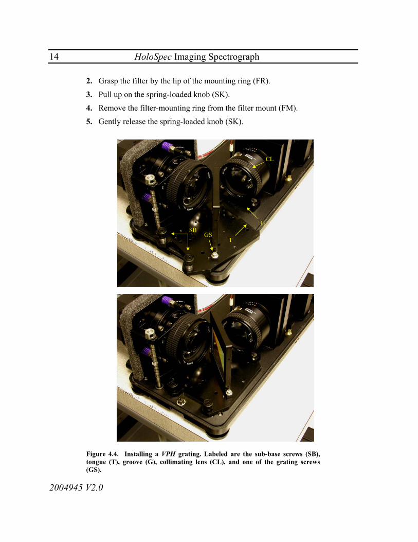
2. Being careful not to touch the surface of the grating, grasp the grating at the top of its mounting frame with one hand and by the sub-base near the screws (SB in Figure 4.4) with the other hand.

HoloSpec Imaging Spectrograph 13
2004945 V2.0
3. Lower the entire assembly into position as shown in Figure 4.4.
4. Snap the tongue (T) of the grating assembly sub-base into the groove (G) of the grating clamp located beneath the collimating lens.
5. Tighten the two large sub-base screws (SB).
To remove a VPH grating Loosen the large sub-base screws (SB) and pull the grating assembly away from the grating clamp beneath the collimating lens (CL).
Caution: Holographic gratings are aligned at the factory. Do not remove the grating screws (GS) that hold the grating onto the sub-base. Tampering with them will misalign the grating.
4.5 Notch Filter (HoloSpec f/1.8i only) A 2"-diameter holographic notch filter, contained in a mounting ring, is easily installed in the notch filter mounting assembly located in the pre-filter section of the spectrograph. The notch filter must be free of fingerprints and lint to provide maximum efficiency. If necessary, clean the filter using standard lens-cleaning methods and materials before installing it.
To install a holographic notch filter 1. Grasp the filter by the mounting ring (FR in Figure 4.5).
2. Pull up on the spring-loaded knob (SK).
3. Slide the filter into the filter mount (FM), making sure that the lip of the filter mounting ring seats firmly against the filter mount.
4. Gently release the spring-loaded knob (SK).
5. Tighten the setscrew (SS) using a 0.05" Allen key or ball driver.
To remove a holographic notch filter 1. Loosen the setscrew (SS in Figure 4.5) using a 0.05" Allen key or ball driver.
14 HoloSpec Imaging Spectrograph
2004945 V2.0
2. Grasp the filter by the lip of the mounting ring (FR).
3. Pull up on the spring-loaded knob (SK).
4. Remove the filter-mounting ring from the filter mount (FM).
5. Gently release the spring-loaded knob (SK).
T
GSB
CL
GS
Figure 4.4. Installing a VPH grating. Labeled are the sub-base screws (SB), tongue (T), groove (G), collimating lens (CL), and one of the grating screws (GS).

HoloSpec Imaging Spectrograph 15
2004945 V2.0
SK
FM
FR
SS
Figure 4.5. Removing the notch filter. Labeled are the spring-loaded knob (SK), setscrew (SS), filter mount (FM), and filter mounting ring (FR).
Caution: Use care when removing the notch filter to avoid damaging the lenses located on either side of the filter mount.
4.6 Input Adapter Five basic types of input adapters are available for use with the HoloSpec: aperture, fiber (FC, SMA, or linear fiber array), and external slit. The aperture input adapter is standard with the HoloSpec f/1.8i or HoloSpecs f/1.4–2.2. The external slit adapter holds a slit in the input adapter support plate and is standard with the HoloSpecs f/1.4–2.2 and optional with the HoloSpec f/1.8i.
All adapters are installed or removed in the same manner, by snapping them into or out of the input adapter support plate (Figure 4.7).

16 HoloSpec Imaging Spectrograph
2004945 V2.0
Aperture Fiber External slit
Figure 4.6. Available input adapters.
To install an input adapter 1. Insert the bottom lip on the rear surface of the input adapter over the ledge
located at the bottom of the input adapter support plate (Figure 4.7).
2. Align the bottom edge of the input adapter and the input adapter support plate so that they are parallel with each other. Push down until the input adapter snaps into place over the ball plunger.
3. Push firmly inward at the top edge of the input adapter until it snaps into place in the input adapter support plate.
Figure 4.7. Installing the input adapter.

HoloSpec Imaging Spectrograph 17
2004945 V2.0
To remove an input adapter 1. Apply thumb pressure to the center of the lower edge of the input adapter until
the top edge snaps out of the input adapter support plate.
2. Lift the input adapter out of the input adapter support plate.
4.7 Aligning the Pre-Filter with Fiber and External Slit Input Adapters (HoloSpec f/1.8i only)
1. Install the input adapter (fiber or external slit) according to the procedure described in Section 4.6.
2. Remove the internal slit (Section 4.3).
3. Illuminate the slit or fiber with a spectral line source, such as a spectral calibration lamp (e.g., neon or argon) or a fluorescent lamp.
4. Adjust the pre-filter section focus by turning the slit focus thumbwheel (SF) to minimize the spectral line width.
5. Insert a 25-µm slit, or the smallest available slit, in the internal slit holder using the procedure described in Section 4.3.
6. Adjust the lateral image position by turning the image adjust thumbwheel (IA) to attain maximum peak height of a spectral line.
IASF
Figure 4.8. Locations of the image adjust thumbwheel (IA) and the slit focus thumbwheel (SF).

18 HoloSpec Imaging Spectrograph
2004945 V2.0
4.8 Aligning the Pre-Filter with the Aperture Input Adapter (HoloSpec f/1.8i only)
The aperture input adapter is intended to be used with user-supplied collection optics. Before performing this procedure, use the image adjust thumbwheel (IA in Figure 4.9) to adjust the user-supplied collection optics so that the sample is imaged approximately into the plane of the exterior surface of the adapter support plate, at the center of the aperture in the aperture input adapter. Small errors in the axial and lateral positions of the image of the sample can be compensated for with the slit focus thumbwheel and the image adjust thumbwheel. Small errors in the lateral position of the image of the sample can be fixed by following this procedure:
1. Install the aperture input adapter (Section 4.6).
2. Remove the slit from the internal slit holder (Section 4.3).
3. Illuminate the sample with the laser.
4. Adjust the slit focus thumbwheel (SF in Figure 4.8) until the sample is focused in the detector. Note that because the image of the sample will be dispersed in the horizontal direction, the spectrograph should be focused so that the vertical extent of the image of the sample is minimized.
5. Insert the smallest available slit in the internal slit holder (Section 4.3).
6. Adjust the image adjust thumbwheel (IA in Figure 4.8) until the signal level observed on the detector is maximized.
4.9 Camera When focusing and aligning the camera, use the smallest available slit, preferably 25-µm. All focus and alignment adjustments are performed with the camera focus, horizontal tilt, and vertical tilt adjustment screws.
Caution: Do not make adjustments other than those controlled by the camera focus thumbwheel, vertical and horizontal tilt adjustment screws. Other lens settings are pre-adjusted at the factory.

HoloSpec Imaging Spectrograph 19
2004945 V2.0
1. Insert the smallest available slit into the internal slit holder (HoloSpec f/1.8i, Section 4.3) or external slit input adapter (HoloSpecs f/1.4–2.2, Section 4.10), if it’s not already in place.
2. Illuminate the slit with a light source that has spectral lines, such as a spectral calibration lamp or a fluorescent lamp. Make sure that the acceptance aperture is filled as uniformly as possible. The light source should be mounted so that the spectrograph is illuminated in as similar a way as possible to normal operation; otherwise the spectral data will show inaccurate band shapes and band centers. Normally, this means that you should mount the light source along the spectrograph’s optical axis.
3. If you are using a CCD as your detector, bin the CCD in two zones, taking a stripe at the top and bottom of the image of the slit (Section 2.6.3 in the HoloGRAMS Operations Manual). If you are using a one-dimensional array, such as a photodiode array, skip to step 5.
Before adjusting the horizontal or vertical tilt adjustment screws (HT and VT in Figure 4.9), remove the black plastic caps and loosen the setscrews that lock the adjustment screws.
4. Adjust the camera focus thumbwheel (CF) and vertical tilt adjustment screw
(VT) until spectral lines located near the center of each stripe are simultaneously in focus (i.e., line width is minimized).
5. Adjust the camera focus thumbwheel (CF) and horizontal tilt adjustment screw (HT) until spectral lines located at the left and right of the detector are simultaneously in focus.
4.10 External Slit Input Adapter The external slit adapter holds a slit in the input support plate. An external slit adapter is standard with the HoloSpecs f/1.4–2.2 and is optional with the HoloSpec f/1.8i.

20 HoloSpec Imaging Spectrograph
2004945 V2.0
HT
VT CF
SS
Figure 4.9. The camera mount, including the horizontal tilt knob (HT) with its setscrew (SS), vertical tilt knob (VT), and camera focus thumbwheel (CF).
Caution: Handle the slit only by its metal carrier—do not touch the thin substrate into which the slit is cut.
To insert a slit into the external slit input adapter 1. Insert the end of the slit with the round tab into the bottom end of the external
slit input adapter, as shown in Figure 4.10.
2. Push down on the slit until it seats itself in the bottom end of the external slit input adapter.
3. Push the slit forward until it snaps into place. Make sure that the slit is seated properly.
To remove a slit from the external slit input adapter, gently push on the button on the back.

HoloSpec Imaging Spectrograph 21
2004945 V2.0
Figure 4.10. Removing a slit from an input adapter.
Caution: When removing the slit, the force of the push button and the ball plungers may throw the slit from the input adapter. Take care to avoid dropping the slit.

22 HoloSpec Imaging Spectrograph
2004945 V2.0
5 Warranty Information Kaiser Optical Systems, Inc., (KOSI) warrants that the product will be free from defects in materials and workmanship when delivered to you, and will perform in accordance with KOSI specifications on the date of delivery and under normal usage for a period of one year from the date of delivery. KOSI makes no warranty or representation with respect to the quality, performance, merchantability, or fitness for a particular purpose of this product. In no event will KOSI be liable for direct, indirect or consequential damages resulting from any defect in the product or manual even if advised of the possibility of such damages. In particular, but not exclusively, KOSI shall have no liability for any business interruption, loss of business profits, manufacturing degradation loss or property or personnel.
Kaiser Optical Systems, Inc., will provide telephone consultation for this product during normal U.S. East Coast business hours 8:00 A.M. to 5:00 P.M. Under no circumstances does telephone consultation affect the terms of any warranty agreement.
If the product fails to meet the standards set out in the warranty, KOSI will, at its discretion, repair or replace it. You must contact KOSI or appropriate dealer to obtain the following information: a Return Material Authorization (RMA) number, information regarding any applicable charges, and the address to which the product must be sent. No merchandise will be accepted by KOSI for any reason without an accurate RMA clearly displayed on the shipping label or documentation of the returned merchandise.
Kaiser Optical Systems, Inc. 371 Parkland Plaza Ann Arbor, MI 48103
Phone: (734) 665-8083 E-mail: [email protected] Fax: (734) 665-8199 Website: www.kosi.com This warranty does not include damage, misuse, negligence, improper installation, unauthorized repair, or adjustments conducted by non-KOSI-authorized operators. Removal of the laser enclosure constitutes immediate termination of the KOSI-offered warranty.
The warranties and remedies set out above are exclusive and in lieu of all other warranties of merchantability, fitness for a particular purpose, and any other warranty whether express, implied, or statutory. No KOSI dealer, value-added reseller, agent, or employee, other than an officer of the company, is authorized to make modification, extension, or addition to this warranty. In the event that any portion of these warranties and remedies are deemed unenforceable, the remaining portions will continue to apply and be enforceable.

HoloSpec Imaging Spectrograph 23
2004945 V2.0
Appendix A. Options The following tables list the available gratings, filters, slits, CCD camera adapters, shutters, and linear fiber array adapters for the HoloSpec spectrographs.
Table A.1. Raman Gratings: Model Number, Spectral Coverage (cm–1, relative to excitation), Average Reciprocal Linear Dispersion (cm–1/pixel), and Part Number.
Excitation Wavelength (nm)
Stokes/Anti-Stokes Grating
Low-Frequency Stokes Grating
High-Frequency Stokes Grating
514.5 HSG-514.5-SA –1054 to 1577 cm–1
2.7 cm–1/pixel 2004370-517
HSG-514.5-LF –204 to 2317 cm–1
2.6 cm–1/pixel 2004370-516
HSG-514.5-HF 2290 to 4491 cm–1
2.2 cm–1/pixel 2004370-515
532 HSG-532-SA –980 to 1559 cm–1
2.6 cm–1/pixel 2004370-520
HSG-532-LF –29 to 2388 cm–1
2.4 cm–1/pixel 2004370-519
HSG-532-HF 2265 to 4387 cm–1
2.1 cm–1/pixel 2004370-518
632.8 HSG-632.8-SA –1150 to 1026 cm–1
2.2 cm–1/pixel 2004370-523
HSG-632.8-LF –2 to 2027 cm–1 2.1 cm–1/pixel 2004370-522
HSG-632.8-HF 1958 to 3735 cm–1
1.8 cm–1/pixel 2004370-521
647 HSG-647-SA –983 to 1127 cm–1
2.1 cm–1/pixel 2004370-526
HSG-647-LF –33 to 1955 cm–1
2.0 cm–1/pixel 2004370-525
HSG-647-HF 1877 to 3620 cm–1
1.8 cm–1/pixel 2004370-524
752 HSG-752-SA –984 to 1173 cm–1
2.2 cm–1/pixel 2004370-529
HSG-752-LF –34 to 1979 cm–1
2.0 cm–1/pixel 2004370-528
HSG-752-HF 1901 to 3622 cm–1
1.7 cm–1/pixel 2004370-527
785 HSG-785-SA –1000 to 1072 cm–1
2.1 cm–1/pixel 2004371-506
HSG-785-LF –34 to 1894 cm–1
2.0 cm–1/pixel 2004371-505
HSG-785-HF 1794 to 3446 cm–1
1.7 cm–1/pixel 2004371-504
830 HSG-830-SA –980 to 987 cm–1
2.0 cm–1/pixel 2004371-509
HSG-830-LF 14 to 1831 cm–1 1.8 cm–1/pixel 2004371-508
HSG-830-HF 1752 to 3306 cm–1
1.6 cm–1/pixel 2004371-507

24 HoloSpec Imaging Spectrograph
2004945 V2.0
Table A.2. Fluorescence and Visible Gratings: Spectral Coverage and Linear Dispersion.
Model Spectral Coverage (nm)
Linear Dispersion (nm/pixel)
Part number
HFG-539.5 411.4 to 667.6 0.26 2004373-514
HFG-550 419.4 to 680.6 0.26 2004373-502
HFG-600 457.6 to 742.4 0.29 2004373-504
HFG-650 495.7 to 804.3 0.31 2004373-506
HFG-730.8 557.3 to 904.3 0.35 2004373-508
HFG-750 571.9 to 928.1 0.36 2004373-510
HFG-850 648.2 to 1051.8 0.41 2004373-512
HVG-590 384.5 to 795.5 0.42 2004372-502
HVG-800 521.3 to 1078.7 0.56 2004372-504
HVG-821 535.0 to 1107.0 0.58 2004372-506

HoloSpec Imaging Spectrograph 25
2004945 V2.0
Table A.3. Holographic Notch Filters.
Model Description
HNPF-632.8AR-2.0 2.0" Holographic SuperNotch-Plus™ Filter, 632.8 nm (AR)
HSPF-532.0AR-2.0 2.0" Holographic SuperNotch-Plus™ Filter, 532 nm (AR)
HSPF-785.0AR-2.0 2.0" Holographic SuperNotch-Plus™ Filter, 785 nm (AR)
HSPF-514.5AR-2.0 2.0" Holographic SuperNotch-Plus™ Filter, 514.5 nm (AR)
HSPF-632.8AR-2.0 2.0" Holographic SuperNotch-Plus™ Filter, 632.8 nm (AR)
Table A.4. Optical Specifications of SuperNotch-PlusTM Filters.
Laser Attenuation Optical density (averaged over entire clear aperture)
> 6.0
Spectral Bandwidth Wavenumbers between O.D. 0.3 or 50% transmission points Nanometers between O.D. 0.3 or 50% transmission points
< 350 cm–1
< 10 nm
Spectral Edgewidth Wavenumbers between O.D. 0.3 and O.D. 4.0 points Nanometers between O.D. 0.3 and O.D. 4.0 points
< 150 cm–1 < 4 nm
Available Wavelength Range 488–1400 nm

26 HoloSpec Imaging Spectrograph
2004945 V2.0
Table A.5. Slits.
Model Number Slit Width (microns unless otherwise indicated)
Part Number
SLIT-25 25 6001215
SLIT-50 50 6001221
SLIT-83 83 2004331-511
SLIT-100 100 6001216
SLIT-167 167 6001217
SLIT-250 250 6001218
SLIT-416 416 6001219
SLIT-500 500 6001222
SLIT-833 833 6001223
SLIT-1000 1000 (1.00 mm) 6001212
SLIT-1670 1670 (1.67 mm) 6001213
SLIT-2000 2 mm 303-20-400
SLIT-4000 4 mm 303-20-461

HoloSpec Imaging Spectrograph 27
2004945 V2.0
Table A.6. Shutters.
Description Part Number
Shutter assembly, 14 mm, dual blade
Shutter only
Connector only
2003668-501
2004257-101
2004257-102
Shutter assembly, 14 mm, single blade
Shutter only
Connector only
2003668-502
2004563-101
2004565-101
Shutter assembly, 25 mm
Shutter only
Connector only
2003668-503
2004257-102
2004258-101
Table A.7. Linear Fiber Array Adapters.
Model Description Part Number
LFAI-10 0.397" Linear Fiber Array Input Adapter Assembly (10 mm)
2004204-502
LFAI-12 0.475" Linear Fiber Array Input Adapter Assembly (12 mm)
2004204-503
LFAI-12.7 0.502" Linear Fiber Array Input Adapter Assembly (12.7 mm)
2004204-504

28 HoloSpec Imaging Spectrograph
2004945 V2.0
Table A.8. SMA Adapter.
Description Part Number
SMA Input Adapter
SMA plunger only
2004058-501
2003113
Table A.9. Adapter Kits for Mounting CCD Cameras to HoloSpec Spectro-graphs.
Model Part Number
Andor DV or DU series 2005721-501
C-Mount 2005459-501
Hamamatsu PMA-100 2005462-501
Photometrics CH250 water-cooled 2005433-501
Photometrics CH250 air-cooled 2005434-501
Photometrics CH260 2005460-501
Photometrics CH270 2005455-501
Photometrics PXL 2005461-501
Princeton LN2-cooled, with shutter 2005430-501
Princeton LN2-cooled, no shutter 2005431-501
Princeton ICCD PentaMAX 2005432-501
Princeton NTE, no shutter 2005439-501
Princeton RTE, no shutter 2005456-501
Santa Barbara Spectrograph Group ST-6 2005436-501
Thermo Oriel 2005721-501
Wright Spectrographs, TE-cooled 2005437-501

HoloSpec Imaging Spectrograph 29
2004945 V2.0
Appendix B. Cleaning Holographic Filters and Gratings
If you need to remove the holographic filter from its filter-mounting ring for cleaning, use the following procedure to avoid damage:
1. Wear finger cots or rubber gloves to avoid leaving fingerprints.
2. Remove the notch filter from the filter mount (FM) as shown in Figure 4.5. Be careful not to touch the surface of the notch filter; grasp it only by the filter-mounting ring (FR).
3. Invert the filter-mounting ring and tap its front surface gently on a surface protected with optical tissues.
4. Follow the directions below, as appropriate. When replacing the notch filter in the filter mount, make sure that the words “Kaiser Optical Systems, Inc.” face toward the slit and transmission grating (Figure 4.5).
Before cleaning, examine the element to determine the type of contamination that is present. It is important to know the types of contaminants and the correct method to remove the contaminant without adversely affecting the surface quality.
Dust, Dirt, or Lint
Carefully remove dust and dirt particles with compressed air or nitrogen or by blowing with a rubber hand syringe. Do not touch the surface. Loosen particles by gently brushing with a camelhair brush, and blow the particles away.
Oil, Grease, or Fingerprints
These contaminants are easily removed immediately after contamination. Use a soft tissue and acetone.
Saliva or Water Spots
Use a water-based cleaning agent to loosen water or saliva spots, followed by acetone to remove the cleaning agent.

30 HoloSpec Imaging Spectrograph
2004945 V2.0
Appendix C. Slit Curvature The following is a sample calculation of the displacement of a ray impinged on a slit 4.000 mm above the optical axis. The general equation is
−−
−=
−
−−
input
output
fxd
dfy
1
11
tancos
sinsinsinsintan λαλα (1)
where
α = input angle (45.00°)
λ = wavelength (784.8 nm)
x = vertical position along input slit (–4.000 to +4.000 mm)
y = displacement from diffracted axis
finput = focal length of input lens (85.00 mm)
foutput = focal length of output lens (85.00 mm)
d = grating fringe spacing (6.076 × 10⁻⁴ mm)
The following is a sample calculation of the displacement from the diffracted axis of a ray with a wavelength (λ) of 784.8 nm striking the top of the input slit (x = +4.000 mm). For the purposes of this calculation, the focal length will be assumed to be 85.00 mm. The calculation will be performed in segments of equation 1, starting with
mm
mmmm
mmf
xdinput
4
141
10076.6
00.85000.4
tancos)10083.6(tancos
−
−−−
×=
×=
(2)
Working out further,
77.3510076.610848.700.45sinsin
10076.6sinsin 4
41
41 −=
××
−=
×− −
−−
−−
mmmm
mmoλα (3)

HoloSpec Imaging Spectrograph 31
2004945 V2.0
and
67.3510083.610848.700.45sinsinsinsin 4
411 −=
××
−=
− −
−−−
mmmm
doλα (4)
Inserting these values into equation (1),
[ ] [ ]mmmm
mmfy output
15.01484.0
)77.35()67.35(tan)00.85()77.35()67.35(tan
≈=
−−−=−−−= (5)
For these conditions, the displacement of the ray at the top of the slit is approximately 0.15 mm.

32 HoloSpec Imaging Spectrograph
2004945 V2.0
Appendix D. List of Approved Distributors For UK and Eire Clairet Scientific Ltd. Moulton Park Industrial Estate Northampton, NN3 6AP UK Tel: 01604-494411 Fax: 01604-494499 For South Korea Doo Ree Tech, Inc Room 303, Seikang Bldg 430-4 Jangan-Dong Dongdaemun-Ku Seoul, 130-101 South Korea Tel: 011 82 22 242 1877 Fax: 011 82 22 242 1879 For Japan S.T. Japan, Inc 1-14-10 Kakigawa-Cho Nihonbashi Chuo-Ku Tokyo, 103 Japan Tel: 011-81-3-3666-2561 Fax: 011-81-3-3666-2658

HoloSpec Imaging Spectrograph 33
2004945 V2.0
Appendix E. List of Kaiser Optical Systems Offices For installation in North America Kaiser Optical Systems, Inc. 371 Parkland Plaza Ann Arbor, MI 48103 USA Tel: +1 734-665-8083 Fax: +1 734-665-8199 For installation in mainland Europe Kaiser Optical Systems, SARL 5 Allée du Moulin Berger - 2ème Etage 69130 Ecully France Tel: (33) 4 37 49 90 73 Fax: (33) 4 37 49 91 03 For installation in the rest of the world Kaiser Optical Systems, Inc. 371 Parkland Plaza Ann Arbor, MI 48103 USA Tel: +1 734-665-8083 Fax: +1 734-665-8199

34 HoloSpec Imaging Spectrograph
2004945 V2.0
This page intentionally left blank