TM Autodesk Inventor - Корпоративный сайт...
25
Shorten the road to done. Autodesk ® Inventor Routed Systems Autodesk ® Inventor TM Routed Systems Suite 2009
Transcript of TM Autodesk Inventor - Корпоративный сайт...

Shorten the road to done.
Autodesk®
InventorRouted Systems
Autodesk®
InventorTM
Routed Systems Suite 2009

2
Autodesk® Inventor™ software provides a comprehensive set of design tools for producing, validating, and documenting complete digital prototypes—helping manufacturers get to market faster with fewer physical prototypes and more innovative products.
Experience your design before it’s built.
The Autodesk Inventor product family is redefining traditional CAD workflows by helping engineers focus on the functional requirements of a design to drive the creation of complex 3D geometry. Reducing the time spent on geometry allows engineers to spend more time innovating designs. By rapidly building digital prototypes that validate a design’s function, engineers can catch errors before they reach production. With creative approaches to accelerate and simplify the concept-to-manufacturing process, Inventor has outsold all competitors for the seventh consecutive year.
The Right Tools for Your Design Process Inventor helps designers to realize the benefits of Digital Prototyping by giving them the freedom to reuse their existing DWG™ designs in a 3D design environment. Inventor lets users read and write native DWG files without risking inaccurate translations, and leverage valuable DWG data to build accurate 3D part models the first time. Inventor includes tools to easily create and document 3D designs, and provides unparalleled interoperability with competitive manufacturing applications—simplifying collaboration with other companies.
Contents
Tube and Pipe Design ............................... 4Cable and Harness Design ....................... 6AutoCAD Integration ................................ 8Part Design ................................................ 10Sheet Metal Part Design ......................... 12Assembly Design ...................................... 14Design and Manufacturing Documentation ......................................... 17Data Management and Communication ................................ 19Customization and Automation ........... 22Learning Resources .................................. 23Learn More ................................................ 24
3
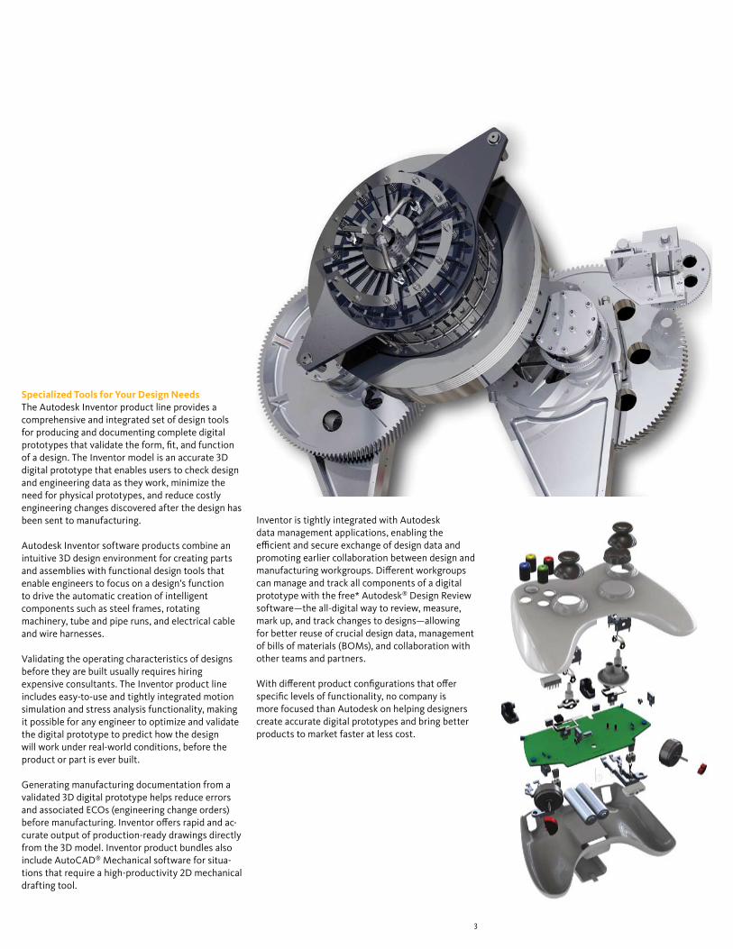
Specialized Tools for Your Design NeedsThe Autodesk Inventor product line provides a comprehensive and integrated set of design tools for producing and documenting complete digital prototypes that validate the form, fit, and function of a design. The Inventor model is an accurate 3D digital prototype that enables users to check design and engineering data as they work, minimize the need for physical prototypes, and reduce costly engineering changes discovered after the design has been sent to manufacturing.
Autodesk Inventor software products combine an intuitive 3D design environment for creating parts and assemblies with functional design tools that enable engineers to focus on a design’s function to drive the automatic creation of intelligent components such as steel frames, rotating machinery, tube and pipe runs, and electrical cable and wire harnesses.
Validating the operating characteristics of designs before they are built usually requires hiring expensive consultants. The Inventor product line includes easy-to-use and tightly integrated motion simulation and stress analysis functionality, making it possible for any engineer to optimize and validate the digital prototype to predict how the design will work under real-world conditions, before the product or part is ever built.
Generating manufacturing documentation from a validated 3D digital prototype helps reduce errors and associated ECOs (engineering change orders) before manufacturing. Inventor offers rapid and ac-curate output of production-ready drawings directly from the 3D model. Inventor product bundles also include AutoCAD® Mechanical software for situa-tions that require a high-productivity 2D mechanical drafting tool.
Inventor is tightly integrated with Autodesk data management applications, enabling the efficient and secure exchange of design data and promoting earlier collaboration between design and manufacturing workgroups. Different workgroups can manage and track all components of a digital prototype with the free* Autodesk® Design Review software—the all-digital way to review, measure, mark up, and track changes to designs—allowing for better reuse of crucial design data, management of bills of materials (BOMs), and collaboration with other teams and partners.
With different product configurations that offer specific levels of functionality, no company is more focused than Autodesk on helping designers create accurate digital prototypes and bring better products to market faster at less cost.

4
Autodesk® Inventor™ Routed Systems Suite enables users to reduce the time required to design tubing, piping, and flexible hose.
Tube and Pipe Design
Functional Route DesignSimplify the design of pipe runs—or spools—to fit in complex assemblies or tight spaces. Automatically routed segments respect predefined routing styles to present users with alternative pipe routes that comply with routing rules such as minimum or maxi-mum length criteria and bend radius. Alternatively, pipe runs can be defined manually by creating 3D sketch geometry or built up interactively using the route edit tools. Automatically routed segments can be combined with user-defined segments for maximum control.
Fittings Library Improve quality, easily organize parts, and eliminate tedious searching with automatic placement of the correct part from an extensive library of piping components. The library includes commonly used, industry-standard (ANSI, DIN, ISO, and JIS) fittings, tubing, piping, and hose. Add or modify proper-ties, including part numbers to existing parts, and control file names used to instance fittings, pipes, tubes, and other content.
Flexible HoseMake sure flexible hose and fittings fit properly using a 3D digital prototype that drives accurate manufacturing documentation. The system inserts appropriate hose fittings from the Content Center and checks for minimum bend radius based on the selected hose style. Hose lengths are updated auto-matically for use in length roll-up commands.
The rules-based routing tools in Inventor Routed Systems Suite select the appropriate fittings and help enable pipe runs to comply with design rules for minimum and maximum length, round-off increments, and bend radius.
5
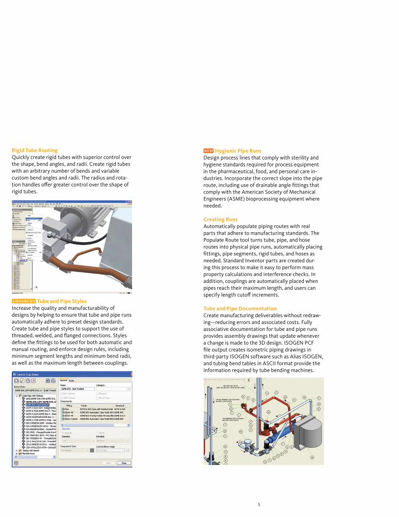
Rigid Tube RoutingQuickly create rigid tubes with superior control over the shape, bend angles, and radii. Create rigid tubes with an arbitrary number of bends and variable custom bend angles and radii. The radius and rota-tion handles offer greater control over the shape of rigid tubes.
Tube and Pipe StylesIncrease the quality and manufacturability of designs by helping to ensure that tube and pipe runs automatically adhere to preset design standards. Create tube and pipe styles to support the use of threaded, welded, and flanged connections. Styles define the fittings to be used for both automatic and manual routing, and enforce design rules, including minimum segment lengths and minimum bend radii, as well as the maximum length between couplings.
Hygienic Pipe RunsDesign process lines that comply with sterility and hygiene standards required for process equipment in the pharmaceutical, food, and personal care in-dustries. Incorporate the correct slope into the pipe route, including use of drainable angle fittings that comply with the American Society of Mechanical Engineers (ASME) bioprocessing equipment where needed.
Creating RunsAutomatically populate piping routes with real parts that adhere to manufacturing standards. The Populate Route tool turns tube, pipe, and hose routes into physical pipe runs, automatically placing fittings, pipe segments, rigid tubes, and hoses as needed. Standard Inventor parts are created dur-ing this process to make it easy to perform mass property calculations and interference checks. In addition, couplings are automatically placed when pipes reach their maximum length, and users can specify length cutoff increments.
Tube and Pipe DocumentationCreate manufacturing deliverables without redraw-ing—reducing errors and associated costs. Fully associative documentation for tube and pipe runs provides assembly drawings that update whenever a change is made to the 3D design. ISOGEN PCF file output creates isometric piping drawings in third-party ISOGEN software such as Alias ISOGEN, and tubing bend tables in ASCII format provide the information required by tube bending machines.

6
Inventor Routed Systems Suite streamlines cable and harness design by using wire list information imported from schematic design packages, including AutoCAD® Electrical software.
Cable and Harness Design
Functional Harness DesignDesign cable and harness components in 3D to reduce manufacturing problems, facilitate output of manufacturing drawings, and avoid late-stage engineering change orders. In Inventor, wire list and connector information is used to drive harness design with built-in cross-checking of electrical and mechanical data so users can make sure that all wires and connectors in the wire list are represented in the 3D cable design.
Wire List InputMaintain electrical design intent and reduce errors when importing wire lists into the assembly. Quickly import large wire lists from AutoCAD Electrical or third-party schematic design applications with de-tection and correction of missing connectors, pins, and wire definitions.
Wire RoutingQuickly route thousands of wires while providing control over the paths of crucial wires. Manual rout-ing requires explicit selection of the wire’s path, in-teractive routing requires selection of the start/end points and the algorithm chooses the shortest path, and in automatic routing the system find the short-est possible path based on all available paths.
Harness Path Definition Optimize the design of cable and harness assem-blies to help ensure proper spacing for manufactur-ing and reduce errors in manufacturing caused by incomplete product definition. Define harness and cable paths using a point-and-click methodology that creates 3D virtual conduits (segments) in the model. Create associative relationships that help ensure that the harness updates when design com-ponents change. Add points or move existing points to refine the overall shape of the harness.
Complex electrical systems are present in almost every product or machine, and require increasingly careful design of the physical cables and harnesses. Incorporating cable and harness runs—including ribbon cables—into the digital prototype saves users time and money by calculating accurate path lengths, avoiding small radius bends, and making sure the electrical components fit into the mechanical assembly.

7
Harness ValidationImprove cable quality and manufacturability, and pre-vent costly recalls and product failures by adhering to design standards. Inventor automatically calculates quality parameters, including bundle diameter, bend radius, and wire lengths, whenever changes are made to the harness. As a result, users can eliminate the time-consuming and error-prone process of manually measuring a hardware prototype.
Harness DocumentationQuickly and easily create manufacturing docu-mentation before building the first article. Since cable and harness geometry is native to Inventor, users can create assembly documentation showing accurate details of cable and harness placement. Comprehensive tools for the rapid generation of harness documentation include the following:
• Automatic nailboard diagrams for 3D wire har-nesses, cables, and ribbon cables that update automatically as the 3D design changes
• Reports including wire run lists, termination charts, cut tables, and other reports needed for the design and manufacture of the harness
• XML output files for transferring the final wire con-nectivity information to streamline the creation of schematics and wiring diagrams using AutoCAD Electrical or other schematic design software
Ribbon CablesReduce errors in the design of electronic equipment by incorporating ribbon cables in the 3D digital proto-type. Add ribbon cables between connectors with full control over the locations of twists and folds.
Connector AuthoringSet up company-specific connector libraries to encourage the use of preferred connectors in the design of electrical products. Inventor includes an extensive library of connectors to simplify selection and placement. The Content Center provides an easy-to-use editor to add user-defined connectors, as well as add or modify properties such as part numbers and default file names used when instanc-ing connectors.

8
Inventor makes it easy for users of AutoCAD® software to realize the benefits of Digital Prototyping by leveraging investments in AutoCAD expertise and DWG™ design data.
AutoCAD Integration
Template SynchronizationOpen a DWG file in Inventor and automatically create layers and dimension and text styles based on the AutoCAD styles in the DWG file, thus reducing the time required to create drawings that comply with customers’ drawing standards.
Ease of UseReduce the time and training required for AutoCAD users to become proficient in 3D design workflows. Simplify the transition from AutoCAD software to Inventor in a familiar design environment with recognizable icons, AutoCAD-compatible shortcuts, cursor-based prompts, and command redo. User profiles enable users to configure Inventor to match the way they work, with out-of-the-box profiles for AutoCAD and Inventor experts. In addition, users can transfer their settings between different computers by exporting the profile to XML.
Inventor delivers the industry’s leading integration of 2D and 3D design, providing direct read and write of native DWG files, while maintaining full associativity to the 3D model—without the need for data-compromising translators.
With Inventor, reuse valuable data with rapid access to existing 2D information. And, because users can save drawings as DWG files, they can easily share insights gained from the digital prototype with partners and suppliers who rely on AutoCAD software. Views generated from 3D part and assembly designs, such as schematics and plant layouts, can also be combined with AutoCAD data. Users can then update 2D drawings by inserting a view of new 3D designs—reducing the cost of upgrading existing equipment.

9
DWG SaveIntegrate DWG technology into the 3D design workflow to take advantage of existing skills; easily combine part, assembly, and schematic drawings data; and streamline communication with suppliers and partners who rely on DWG technology. This feature stores Inventor drawing views in the DWG file to provide view, plot, and measure capabilities in AutoCAD with complete visual fidelity, while preserving fully associative drawing updates.
Direct DWG OpenGain access to existing 2D design data without installing or learning AutoCAD software. Open AutoCAD drawings directly in the Inventor ap-plication to view, plot, and measure using familiar Inventor commands. Incorporate existing 2D design data into 3D design workflows using Copy and Paste commands.
AutoCAD Blocks from Inventor ViewsReduce the cost of using 3D for upgrade projects originally designed in 2D. This feature generates AutoCAD blocks from Inventor drawing views so users can redesign subassemblies using Inventor and then integrate the new drawing views directly into the original drawings.
Inventor and AutoCAD Mechanical InteroperabilityAccelerate time to market and reduce errors by enabling associative 2D and 3D collaboration. With this interoperability, AutoCAD Mechanical software creates drawings of Inventor components by enabling users to open native Inventor parts and assemblies. When the design changes in Inventor, the AutoCAD Mechanical drawing is automatically updated.

10
Inventor software helps designers reach the next level of efficiency by making it easier to reuse design data, convey design intent, and work with fully associative models to make sure any changes to the part design are reflected in the assembly model and drawing files.
Part Design
SketchingEvaluate different design ideas before creating detailed part and assembly models. By using theInventor sketch environment, designers can quickly capture design ideas as versatile 2D layouts. By combining the power of constraints with easy-to-use tools for modifying sketches, designers can try different design concepts and control color and line style to help convey design ideas.
Improve productivity by automating repetitive design workflows for frequently used custom features and parts. Using the iPart technology in Inventor, companies can easily set up libraries of intelligent parts to make sure that frequently used parts are created the same way every time.
11
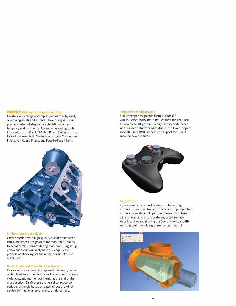
Advanced Shape DescriptionCreate a wide range of complex geometries by easily combining solids and surfaces. Inventor gives users precise control of shape characteristics, such as tangency and continuity. Advanced modeling tools include Loft to a Point, N-Sided Patch, Sweep Normal to Surface, Area Loft, Centerline Loft, G2 Continuous Fillets, Full Round Fillets, and Face-to-Face Fillets.
Surface Quality AnalysisCreate models with high-quality surface character-istics, and check design data for manufacturability to avoid costly changes during manufacturing setup. Zebra and Gaussian analysis tools simplify the process of checking for tangency, continuity, and curvature.
Draft Angle and Cross Section AnalysisCross section analysis displays wall thickness, color-coded feedback of minimum and maximum thickness violations, and moment of inertia at the end of the cross section. Draft angle analysis displays color-coded draft angle based on a pull direction, which can be defined by an axis, plane, or planar face.
Import from AliasStudioUse concept design data from Autodesk® AliasStudio™ software to reduce the time required to complete 3D product design. Incorporate curve and surface data from AliasStudio into Inventor part models using DWG import and export tools built into the two products.
Sculpt ToolQuickly and easily modify shape details using surfaces from Inventor or by incorporating imported surfaces. Construct 3D part geometry from closed set surfaces, and incorporate imported surface data into the model using the Sculpt tool to modify existing parts by adding or removing material.

12
Autodesk Inventor helps users simplify the design of complex sheet metal parts.
Sheet Metal Part Design
Sheet Metal FlangesQuickly design sheet metal parts in 3D that accommodate specific manufacturing processes and shop capabilities. Edge chaining allows creation of multiple flanges in a single stop, while rich unfold options and automatic mitering reduce the time required to define the folded part model.
Sheet Metal StylesGenerate flat patterns that accurately reflect your manufacturing capabilities. Sheet metal unfolding is controlled through styles that define the material thickness, bend rules, and corner reliefs. Both linear unfolding and custom bend tables can be used to control the unfolding geometry.
Inventor improves productivity during the design of sheet metal parts by providing a digital prototype that combines manufacturing information (such as punch tool parameters and custom bend tables) with an accurate 3D model of sheet metal folding and a flat pattern editing environment where manufacturing engineers can tweak flat patterns to optimize manufacturing costs.

13
Flat Pattern FeaturesGenerate optimized flat patterns to eliminate unnecessary manufacturing costs. Unfold sheet metal models to create flat patterns with associative flat-pattern editing to support cleanup operations such as modifying corner reliefs to match specific capabilities available on the shop floor.
Punch LibrariesUsers can define their own sheet metal punch libraries to standardize punch usage and reduce computer numerical control (CNC) tooling costs. Table-driven punches enable users to define families of punches, typically different sizes of the same punch shape with full representation of manufacturing parameters, including PunchID, punch depth, and sketches for alternate punch representations.
Sheet Metal FastenersQuickly insert specialized sheet metal fasteners in the sheet metal design. A comprehensive range of PEM™ fasteners are included in the Content Center.
DXF OutputReduce programming time by eliminating time spent cleaning up DXF™ files for CNC machining. DXF/DWG export for sheet metal provides control of preprocessing and postprocessing options such as DXF/DWG file version, layer mapping, user-defined chord length for spline simplification, and customization through external XML files.
Sheet Metal Manufacturing DrawingsQuickly create accurate manufacturing drawings to support sheet metal manufacturing operations. Document flat pattern drawings by inserting punch notes, punch tables, and bend tables that display punch and bend data from the 3D mode and select display of bend directions using drawing styles.

14
Inventor combines Design Accelerators with easy-to-use assembly tools so users can be sure that every part and component in an assembly design fits correctly.
Assembly Design
Assembly DesignQuickly assemble individual parts and subassemblies to define the complete product structure and verify that the product can be assembled. Insert and position new components in the assembly using constraints to capture the positional relationships that define fixed and moving components.
Accurately validate interference and mass properties to produce high-quality products the first time around. Inventor provides the tools to control and manage the data created by large assembly designs so users can work on just the components required to complete a particular part of the design.

15
Interference Analysis and Contact DetectionEliminate costly errors and improve manufacturability by testing assembly function within Inventor. Check for both static interference between parts with graphic highlighting of overlapping material, and then test for potential collisions between moving parts by driving assembly constraints or dragging components until they collide.
AutoLimitsReduce errors and engineering changes through automatic monitoring of crucial design parameters. Use AutoLimits to monitor length, distance, angle, diameter, loop length, area, volume, and mass. AutoLimits icons change color when the monitored parameters exceed the prescribed parameter range.
Assembly ConfigurationsEasily design and document product families using assembly configurations to define variations from a master assembly. Exclude or substitute individual components and make changes to dimension and constraint values. Then document the whole part or assembly configuration using the Table tool, which automatically creates the parameter table in a 2D drawing.
Large Assembly ManagementRealize the benefits of 3D design when developing very large assemblies. With level of detail (LOD) representations, users have full control over how much information to load when working with large assemblies. Control memory consumption by suppressing components. A large assembly “capacity meter” provides a visual indication of how much memory is available.
Design AcceleratorsMove beyond 2D drafting and 3D modeling to rapidly design, analyze, and generate commonly used machine components from the functional requirements and specifications such as power, speed, torque, material properties, working temperatures, and lubrication conditions. Inventor software includes Design Accelerators for bolted connections, shafts, bearings, O-rings, spur gears, belt and chain drives, pins, and springs.

16
Frame GeneratorQuickly design and develop welded frames for industrial machinery applications. The Frame Generator builds up structural frames by dropping predefined steel shapes onto wireframe or solid skeletal frames and simplifies creation of end conditions with predefined options for mitered, notched, and straight butt welded joints. It includes profile authoring so users can add custom profiles to the existing library of standard profiles.
WeldmentsImprove quality and documentation of welded assemblies. Define weld preparation, weld creation, and postweld operations with full 3D representation of fillet, gap, or groove welds that provide weldment analysis and bead volume reports. Automatically create 3D annotation based on industry or company standards, and generate associative 2D weld symbols for documentation.
Content CenterThe Content Center provides fast and easy access to frequently used content, simplifying creation, reuse, and management of all standard company content. The Content Center is a centralized library for engineering content that provides an easy-to-use content browser with search and filter tools to help users quickly find the right part families. It includes more than 650,000 components—such as nuts, bolts, and screws—and enables companies to add in-house parts and standard features to user-defined libraries.
Supplier Content Center Reduce the time and effort required to incorporate standard components into designs. The Supplier Content Center provides web-based access to component models from more than 100 leading manufacturers. The simple-to-use browser provides quick and easy access to models in native Inventor format. And it is fully integrated with the Autodesk Inventor Content Center.
Design DoctorUse the Design Doctor™ feature to find and fix errors in 3D models. This diagnostic tool identifies potential design issues and recommends corrections.
Assembly Level STL OutputQuickly create source stereolithography (STL) files directly from the Inventor assembly environment for rapid prototyping of Inventor assemblies.
17
Design and Manufacturing Documentation
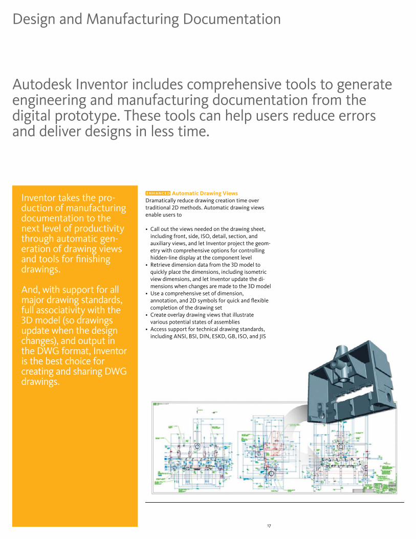
Autodesk Inventor includes comprehensive tools to generate engineering and manufacturing documentation from the digital prototype. These tools can help users reduce errors and deliver designs in less time.
Automatic Drawing ViewsDramatically reduce drawing creation time over traditional 2D methods. Automatic drawing views enable users to
• Call out the views needed on the drawing sheet, including front, side, ISO, detail, section, and auxiliary views, and let Inventor project the geom-etry with comprehensive options for controlling hidden-line display at the component level
• Retrieve dimension data from the 3D model to quickly place the dimensions, including isometric view dimensions, and let Inventor update the di-mensions when changes are made to the 3D model
• Use a comprehensive set of dimension, annotation, and 2D symbols for quick and flexible completion of the drawing set
• Create overlay drawing views that illustrate various potential states of assemblies
• Access support for technical drawing standards, including ANSI, BSI, DIN, ESKD, GB, ISO, and JIS
Inventor takes the pro-duction of manufacturing documentation to the next level of productivity through automatic gen-eration of drawing views and tools for finishing drawings.
And, with support for all major drawing standards, full associativity with the 3D model (so drawings update when the design changes), and output in the DWG format, Inventor is the best choice for creating and sharing DWG drawings.
18
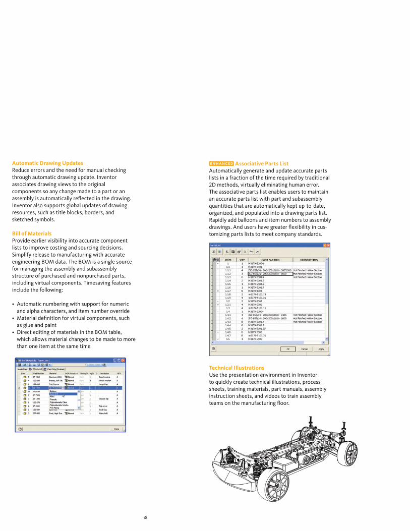
Automatic Drawing UpdatesReduce errors and the need for manual checking through automatic drawing update. Inventor associates drawing views to the original components so any change made to a part or an assembly is automatically reflected in the drawing. Inventor also supports global updates of drawing resources, such as title blocks, borders, and sketched symbols.
Bill of MaterialsProvide earlier visibility into accurate component lists to improve costing and sourcing decisions. Simplify release to manufacturing with accurate engineering BOM data. The BOM is a single source for managing the assembly and subassembly structure of purchased and nonpurchased parts, including virtual components. Timesaving features include the following:
• Automatic numbering with support for numeric and alpha characters, and item number override
• Material definition for virtual components, such as glue and paint
• Direct editing of materials in the BOM table, which allows material changes to be made to more than one item at the same time
Associative Parts ListAutomatically generate and update accurate parts lists in a fraction of the time required by traditional 2D methods, virtually eliminating human error. The associative parts list enables users to maintain an accurate parts list with part and subassembly quantities that are automatically kept up-to-date, organized, and populated into a drawing parts list. Rapidly add balloons and item numbers to assembly drawings. And users have greater flexibility in cus-tomizing parts lists to meet company standards.
Technical IllustrationsUse the presentation environment in Inventor to quickly create technical illustrations, process sheets, training materials, part manuals, assembly instruction sheets, and videos to train assembly teams on the manufacturing floor.

19
Data Management and Communication
Inventor enables the efficient and secure exchange of design data to support collaboration between different engineering contributors, including industrial design, product design, and manufacturing.
Autodesk Vault IntegrationAutodesk® Vault data management software is a centralized application for workgroups that securely stores and manages work-in-progress design data and related documents. Use it to maximize return on your company’s investment in design data by driving design reuse.
Autodesk ProductstreamHelp ensure that your company’s designs are complete, accurate, approved, and released to manufacturing in a timely and effective manner. Autodesk® Productstream® software (sold separately) automates the release management process by managing engineering changes and BOMs while the engineering department maintains control of the design data.
Autodesk Inventor StudioImprove communication with customers and other decision makers by creating high-quality photorealistic renderings and animations in the Inventor design environment. Autodesk® Inventor™ Studio software gives design engineers direct access to this specialized and typically expensive functionality. Mirror and turntable animation tools and a streamlined user interface reduce the time required to set up and create cyclic animation sequences.
This capability allows design workgroups to manage and track all the design components of a digital prototype, helping designers reuse crucial design data, man-age BOMS, and promote earlier collaboration with manufacturing teams and clients.
Through a comprehensive suite of native translators, Inventor provides the interoperability that en-ables companies to take on projects in which part of the 3D data originates from other CAD systems and satisfy customer requests for 3D models in other native formats.

20
DWF PublishingImprove product quality, decrease time to market, and reduce scrap and rework costs by using DWF™ technology to streamline communication with suppliers, purchasing, and other supply chain partners. Publish the information required by manufacturing partners, including assembly animations and detailed step-by-step assembly instructions, 2D drawings, and 3D models with BOM information.
Publishing FormatsShare product information with partners and customers who need to incorporate your designs into their products. Publish Inventor drawings as PDF files, publish 3D part and assembly models in SAT or JT format, and create STL files for output to stereolithography and 3D print machines.
DWF MarkupEasily track, manage, and verify multiple markups and design changes throughout the design review process. Overlay DWF markups directly onto Inventor drawings, provide status, and make changes. Users can then republish or “round-trip” those changes back to the design reviewer to complete the process.
Data Management and Communication

21
AEC ExchangeThe AEC (Architecture, Engineering, and Construction) Exchange tool creates and pub-lishes simplified 3D representations, intelligent connection points, and additional information in native file formats for AutoCAD® MEP software. Users can also export 3D geometry to AutoCAD® Architecture, Revit®-based software, and AutoCAD software.
Native TranslatorsStreamline projects that require opening files from vendors or customers in native formats. Deliver 3D design data to customers or vendors who prefer native file formats. Users can easily exchange data between Autodesk Inventor, UGS,® SolidWorks,® and Pro/ENGINEER® by importing and exporting Parasolid,® importing UG-NX,™ importing SolidWorks, importing and exporting Granite, and importing Pro/ENGINEER directly with Inventor.
STEP/IGESSimplify accurate collaboration with suppliers and customers by enabling sharing and reuse of design data with 3D CAD/CAM systems. Read and write design and drawing data using industry-standard formats.
Construction EnvironmentReduce the time required to inspect and repair customer data files. The Inventor Construction Environment provides fault-tolerant import of large STEP and IGES data sets, with a quarantine to hold entities containing geometric problems such as sur-face slivers and mismatched boundary curves. The construction environment also includes a compre-hensive toolkit for inspecting, editing, and correct-ing quarantined entities, including solids, surfaces, wireframes, and points. Data sets can be corrected and promoted into 3D part models, surfaces, or 3D wireframes.
22
Customization and Automation
Inventor helps users make the most of their investment in 3D by using the Inventor API (application programming interface) to streamline frequently used procedures and automate specialized workflows that support design standards and engineering processes.
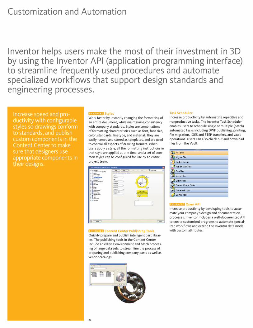
StylesWork faster by instantly changing the formatting of an entire document, while maintaining consistency with company standards. Styles are combinations of formatting characteristics such as font, font size, color, standards, linetype, and material. They are easily named and stored as templates, and are used to control all aspects of drawing formats. When users apply a style, all the formatting instructions in that style are applied at one time, and a set of com-mon styles can be configured for use by an entire project team.
Content Center Publishing ToolsQuickly prepare and publish intelligent part librar-ies. The publishing tools in the Content Center include an editing environment and batch process-ing of large data sets to streamline the process of preparing and publishing company parts as well as vendor catalogs.
Task SchedulerIncrease productivity by automating repetitive and nonproductive tasks. The Inventor Task Scheduler enables users to schedule single or multiple (batch) automated tasks including DWF publishing, printing, file migration, IGES and STEP transfers, and vault operations. Users can also check out and download files from the Vault.
Open APIIncrease productivity by developing tools to auto-mate your company’s design and documentation processes. Inventor includes a well-documented API to create customized programs to automate special-ized workflows and extend the Inventor data model with custom attributes.
Increase speed and pro-ductivity with configurable styles so drawings conform to standards, and publish custom components in the Content Center to make sure that designers use appropriate components in their designs.

23
Inventor offers a range of learning and reference resources to help users maintain skills and quickly make the most of the 3D design environment.
Learning Resources
Advanced Help SystemSpeed the transition to 3D with contextual help. The advanced help system is easier to use with improved navigation and profiles that present users with the right information based on their user profile.
Tutorials and Skill BuildersUse extended learning modules, including tutorials with Show Me animations and Skill Builders, to enhance understanding and skills.
E-Learning Accelerate learning through flexible access to tutorials and best practices. A valuable component of Autodesk® Subscription, e-Learning provides a continually expanding curriculum of short training exercises.
Deployment GuideComplete the installation of Inventor with minimum time and effort. Whether you are planning a new deployment or upgrading to Autodesk Inventor 2009, this easy-to-read booklet provides the information you need to succeed.
Engineer’s Handbook Save time researching engineering formulas, tables, and standards. The Engineer’s Handbook provides a comprehensive online reference of engineering theory, formulas, and algorithms, and a manufacturing knowledge base that is easily accessible from anywhere in Inventor.
With Inventor, users can learn new skills, look up information about procedures and tools, and get the latest tips and tricks needed to stay productive.

24
Autodesk Inventor Suite 2009
Autodesk Inventor Routed Systems Suite 2009
Autodesk Inventor Simulation Suite 2009
Autodesk Inventor Professional 2009
Autodesk Inventor • • • •
AutoCAD Mechanical • • • •
Cable and Harness Design • •
Tube, Pipe, and Flexible Hose Design • •
Stress Analysis (FEA) • •
Dynamic Simulation • •
Autodesk Vault • • • •
Learn about the different Inventor products available to fit your specific design needs, and discover why Inventor products are the best choice for manufacturing companies. For more information, visit www.autodesk.com/inventor.
Learn More
24

Heading large > KievitPro Regular 23 on 23 pt, 75% black. Ut enim ad mini mim veniami quis nostrud exercitation ullam, corpor suscipit laboris Lorem ipsum etalus siti amet, duis autem conitu secutur adipscing elitsef diam eiusmod magnus. Etion ullam, corpor suscipit laboris Lorem ipsum etalus siti amet, duis autem conitu secutur adipscing elitsef diam eiusmod magnus.
Text heading > KievitPro Bold 8.5 on 10.5 pt, product family colorBody Text > KievitPro Regular 8.5 on 10.5 pt, black. lorem ipsum etalus sit amet, duis autem consecutur adipscing elit, sef diam nonumy eiusmod tempor incident ut labore magna aliquam erat volupat. Ut enim ad minimim veniami quis nostrud exercitation ullam, corpor suscipit laboris nisi ut aliquip ex ea commodo conseauat. Duis autem vel eum irure etalus in reprehjenderit in volupate velit ewsse moestai xom consequat.
Text headingBody Text. Vel illum etalusim eu fugiat nulla pariartur—ignissim qui blandit praes entl upatum delenit aigue duos etalus et molestais excepturisio toccaecet cupidat non. Lorem ipsum etalus sit amet, duis autem consecutur adipscing elit, sef diam nonumy eiusmod te mpor incident ut labore magna aliquam erat.
Text headingBody text. Lorem ipsum etalus sit amet, duis autem consecutur adipscing elit, sef diam nonumy eiusmod tempor incident ut labore magna aliquam erat volupat. Ut enim ad minimim veniami quis nostrud exercitation ullam, corpor suscipit laboris nisi ut aliquip ex ea commodo conseauat. Duis autem vel eum irure etalus in reprehjenderit.
Legal text > KievitPro Regular 6 on 8 pt, black — Registered trademarks of Autodesk, Inc., in the USA and/or other countries. All other product names, brand names, or trademarks belong to their respective holders. © 2008 Autodesk, Inc. All rights reserved. part number
*Free products are subject to the terms and conditions of the end-user license agreement that accompanies download of the software.
Cover image courtesy of SkidTek Engineering
Autodesk, AutoCAD, AliasStudio, Autodesk Inventor, Design Doctor, DWF, DWG, DXF, Inventor, Productstream, and Revit are registered trademarks or trademarks of Autodesk, Inc., in the USA and/or other countries. All other brand names, product names, or trademarks belong to their respective holders. Autodesk reserves the right to alter product offerings and specifications at any time without notice, and is not responsible for typographical or graphical errors that may appear in this document. © 2008 Autodesk, Inc. All rights reserved. 000000000000118268
Digital Prototyping for the Manufacturing Market
Autodesk is a world-leading supplier of engineering software, providing companies with tools to experience their ideas before they are real. By putting powerful Digital Prototyping technology within the reach of mainstream manufacturers, Autodesk is changing the way manufacturers think about their design processes and is helping them create more productive workflows. The Autodesk approach to Digital Prototyping is unique in that it is scalable, attainable, and cost-effective, which allows a broader group of manufacturers to realize the benefits with minimal disruption to existing workflows, and provides the most straightforward path to creating and maintaining a single digital model in a multidisciplinary engineering environment.
Learn More or PurchaseAccess specialists worldwide who can provide product expertise, a deep understanding of your industry, and value that extends beyond your software purchase. To purchase Autodesk Inventor software contact an Autodesk Premier Solutions Provider or Autodesk Authorized Reseller. To locate the reseller nearest you, visit www.autodesk.com/reseller.
Learn about the different Inventor products available to fit your specific design needs, and discover why Inventor products are the best choice for manufacturing companies. For more information, visit www.autodesk.com/inventor.
Autodesk Services and SupportAccelerate return on investment and optimize productivity with innovative purchase methods, companion products, consulting services, support, and training from Autodesk and Autodesk authorized partners. Designed to get you up to speed and keep you ahead of the competition, these tools help you make the most of your software purchase—no matter what industry you are in. To learn more, visit www.autodesk.com/servicesandsupport.
Autodesk SubscriptionGet the benefits of increased productivity, predictable budgeting, and simplified license management with Autodesk Subscription. You get any new upgrades of your Autodesk software and any incremental product enhancements, if these are released during your subscription term, and you get exclusive license terms available only to subscription members. A range of community resources, including web support direct from Autodesk technical experts, self-paced training, and e-Learning, help extend your skills and make Autodesk Subscription the best way to optimize your investment. To learn more, visit www.autodesk.com/subscription.